WO2021054445A1 - 有機ハイドライド生成システムの制御方法および有機ハイドライド生成システム - Google Patents
有機ハイドライド生成システムの制御方法および有機ハイドライド生成システム Download PDFInfo
- Publication number
- WO2021054445A1 WO2021054445A1 PCT/JP2020/035488 JP2020035488W WO2021054445A1 WO 2021054445 A1 WO2021054445 A1 WO 2021054445A1 JP 2020035488 W JP2020035488 W JP 2020035488W WO 2021054445 A1 WO2021054445 A1 WO 2021054445A1
- Authority
- WO
- WIPO (PCT)
- Prior art keywords
- electrode
- deterioration rate
- cathode
- potential
- anode
- Prior art date
- Legal status (The legal status is an assumption and is not a legal conclusion. Google has not performed a legal analysis and makes no representation as to the accuracy of the status listed.)
- Ceased
Links
Images

Classifications
-
- C—CHEMISTRY; METALLURGY
- C25—ELECTROLYTIC OR ELECTROPHORETIC PROCESSES; APPARATUS THEREFOR
- C25B—ELECTROLYTIC OR ELECTROPHORETIC PROCESSES FOR THE PRODUCTION OF COMPOUNDS OR NON-METALS; APPARATUS THEREFOR
- C25B1/00—Electrolytic production of inorganic compounds or non-metals
- C25B1/01—Products
- C25B1/02—Hydrogen or oxygen
- C25B1/04—Hydrogen or oxygen by electrolysis of water
-
- C—CHEMISTRY; METALLURGY
- C25—ELECTROLYTIC OR ELECTROPHORETIC PROCESSES; APPARATUS THEREFOR
- C25B—ELECTROLYTIC OR ELECTROPHORETIC PROCESSES FOR THE PRODUCTION OF COMPOUNDS OR NON-METALS; APPARATUS THEREFOR
- C25B15/00—Operating or servicing cells
- C25B15/02—Process control or regulation
-
- C—CHEMISTRY; METALLURGY
- C25—ELECTROLYTIC OR ELECTROPHORETIC PROCESSES; APPARATUS THEREFOR
- C25B—ELECTROLYTIC OR ELECTROPHORETIC PROCESSES FOR THE PRODUCTION OF COMPOUNDS OR NON-METALS; APPARATUS THEREFOR
- C25B15/00—Operating or servicing cells
- C25B15/02—Process control or regulation
- C25B15/023—Measuring, analysing or testing during electrolytic production
- C25B15/025—Measuring, analysing or testing during electrolytic production of electrolyte parameters
- C25B15/033—Conductivity
-
- C—CHEMISTRY; METALLURGY
- C25—ELECTROLYTIC OR ELECTROPHORETIC PROCESSES; APPARATUS THEREFOR
- C25B—ELECTROLYTIC OR ELECTROPHORETIC PROCESSES FOR THE PRODUCTION OF COMPOUNDS OR NON-METALS; APPARATUS THEREFOR
- C25B3/00—Electrolytic production of organic compounds
-
- C—CHEMISTRY; METALLURGY
- C25—ELECTROLYTIC OR ELECTROPHORETIC PROCESSES; APPARATUS THEREFOR
- C25B—ELECTROLYTIC OR ELECTROPHORETIC PROCESSES FOR THE PRODUCTION OF COMPOUNDS OR NON-METALS; APPARATUS THEREFOR
- C25B3/00—Electrolytic production of organic compounds
- C25B3/01—Products
- C25B3/03—Acyclic or carbocyclic hydrocarbons
-
- C—CHEMISTRY; METALLURGY
- C25—ELECTROLYTIC OR ELECTROPHORETIC PROCESSES; APPARATUS THEREFOR
- C25B—ELECTROLYTIC OR ELECTROPHORETIC PROCESSES FOR THE PRODUCTION OF COMPOUNDS OR NON-METALS; APPARATUS THEREFOR
- C25B3/00—Electrolytic production of organic compounds
- C25B3/01—Products
- C25B3/05—Heterocyclic compounds
-
- C—CHEMISTRY; METALLURGY
- C25—ELECTROLYTIC OR ELECTROPHORETIC PROCESSES; APPARATUS THEREFOR
- C25B—ELECTROLYTIC OR ELECTROPHORETIC PROCESSES FOR THE PRODUCTION OF COMPOUNDS OR NON-METALS; APPARATUS THEREFOR
- C25B3/00—Electrolytic production of organic compounds
- C25B3/01—Products
- C25B3/09—Nitrogen containing compounds
-
- C—CHEMISTRY; METALLURGY
- C25—ELECTROLYTIC OR ELECTROPHORETIC PROCESSES; APPARATUS THEREFOR
- C25B—ELECTROLYTIC OR ELECTROPHORETIC PROCESSES FOR THE PRODUCTION OF COMPOUNDS OR NON-METALS; APPARATUS THEREFOR
- C25B3/00—Electrolytic production of organic compounds
- C25B3/20—Processes
- C25B3/25—Reduction
-
- C—CHEMISTRY; METALLURGY
- C25—ELECTROLYTIC OR ELECTROPHORETIC PROCESSES; APPARATUS THEREFOR
- C25B—ELECTROLYTIC OR ELECTROPHORETIC PROCESSES FOR THE PRODUCTION OF COMPOUNDS OR NON-METALS; APPARATUS THEREFOR
- C25B9/00—Cells or assemblies of cells; Constructional parts of cells; Assemblies of constructional parts, e.g. electrode-diaphragm assemblies; Process-related cell features
- C25B9/17—Cells comprising dimensionally-stable non-movable electrodes; Assemblies of constructional parts thereof
- C25B9/19—Cells comprising dimensionally-stable non-movable electrodes; Assemblies of constructional parts thereof with diaphragms
- C25B9/23—Cells comprising dimensionally-stable non-movable electrodes; Assemblies of constructional parts thereof with diaphragms comprising ion-exchange membranes in or on which electrode material is embedded
-
- Y—GENERAL TAGGING OF NEW TECHNOLOGICAL DEVELOPMENTS; GENERAL TAGGING OF CROSS-SECTIONAL TECHNOLOGIES SPANNING OVER SEVERAL SECTIONS OF THE IPC; TECHNICAL SUBJECTS COVERED BY FORMER USPC CROSS-REFERENCE ART COLLECTIONS [XRACs] AND DIGESTS
- Y02—TECHNOLOGIES OR APPLICATIONS FOR MITIGATION OR ADAPTATION AGAINST CLIMATE CHANGE
- Y02E—REDUCTION OF GREENHOUSE GAS [GHG] EMISSIONS, RELATED TO ENERGY GENERATION, TRANSMISSION OR DISTRIBUTION
- Y02E60/00—Enabling technologies; Technologies with a potential or indirect contribution to GHG emissions mitigation
- Y02E60/30—Hydrogen technology
- Y02E60/36—Hydrogen production from non-carbon containing sources, e.g. by water electrolysis
Definitions
- the present invention relates to a control method for an organic hydride production system and an organic hydride production system.
- an organic hydride generator including an anode that generates protons from water and a cathode that hydrogenates an organic compound having an unsaturated bond is known (see, for example, Patent Document 1).
- this organic hydride generator hydrogen is added to the hydride and an organic hydride is obtained by supplying water to the anode and passing a current between the anode and the cathode while supplying the hydride to the cathode. ..
- the above-mentioned organic hydride generator is generally operated continuously using stable electric power such as energy obtained by thermal power generation. Therefore, the stop of the organic hydride generator is mainly due to the intentional stop of the power supply, and it is relatively easy to take measures against the deterioration of the electrodes due to the stop.
- the problems in the system for producing organic hydride by combining renewable energy and the organic hydride generator have not been sufficiently studied.
- the present inventors have conducted diligent studies, and as a result, electrodes caused by a large number of times when power supply of renewable energy is stopped. We have come up with a technology that suppresses the deterioration of the organic hydride generation system and further improves the durability of the organic hydride generation system.
- the present invention has been made in view of such a situation, and one of the objects thereof is to provide a technique for improving the durability of an organic hydride production system.
- One aspect of the present invention is a control method for an organic hydride generation system including an electrolytic cell that produces an organic hydride and a power source that supplies an electrolytic current to the electrolytic cell.
- the electrolytic tank houses an anode electrode for oxidizing water to generate protons, a cathode electrode for hydrogenating a product to be hydrogenated with protons to generate an organic hydride, an anode chamber for accommodating the anode electrode, and a cathode electrode. It has a cathode chamber and a diaphragm separating the anode chamber and the cathode chamber.
- the anode electrode has a degradation characteristic that the electrolytic current is deteriorated by a predetermined deterioration rate d AN by a potential change that occurs during the stop operation is not supplied to the electrolytic cell, the cathode electrode, the predetermined by the potential changes that occur during shutdown degradation It has a deterioration characteristic that deteriorates at a rate d CA.
- the potentials of the anode electrode and the cathode electrode are adjusted so that the potential change of the electrode having a large deterioration rate is smaller than the potential change of the electrode having a small deterioration rate among the anode electrode and the cathode electrode. Including controlling.
- This organic hydride generation system has an anode electrode for oxidizing water to generate protons, a cathode electrode for hydrogenating a product to be hydrogenated with protons to generate organic hydride, an anode chamber for accommodating the anode electrode, and a cathode electrode. It is provided with a cathode chamber for accommodating the anode chamber, an electrolytic tank having a diaphragm for partitioning the anode chamber and the cathode chamber, a power source for supplying an electrolytic current to the electrolytic tank, and a control unit for controlling the potentials of the anode electrode and the cathode electrode.
- the anode electrode has a degradation characteristic that the electrolytic current is deteriorated by a predetermined deterioration rate d AN by a potential change that occurs during the stop operation is not supplied to the electrolytic cell, the cathode electrode, the predetermined by the potential changes that occur during shutdown degradation It has a deterioration characteristic that deteriorates at a rate d CA.
- the control unit controls the potentials of the anode electrode and the cathode electrode so that the potential change of the electrode having a large deterioration rate among the anode electrode and the cathode electrode is smaller than the potential change of the electrode having a small deterioration rate.
- the durability of the organic hydride production system can be improved.
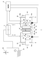
- FIG. 1 is a schematic diagram of an organic hydride production system according to an embodiment.
- the organic hydride generation system 1 includes an electrolytic cell 2, a power source 4, a first distribution mechanism 6, a second distribution mechanism 8, and a control unit 10.
- the electrolytic cell 2 is an electrolytic cell that produces an organic hydride by hydrogenating a hydride, which is a dehydrogenated product of the organic hydride, by an electrochemical reduction reaction.
- the electrolytic cell 2 has an anode electrode 12, an anode chamber 14, a cathode electrode 16, a cathode chamber 18, and a diaphragm 20.
- the anode electrode 12 is an electrode (anode) for oxidizing water to generate protons.
- the anode electrode 12 has a catalyst layer 12a and a gas diffusion layer 12b.
- the catalyst layer 12a contains, for example, iridium (Ir) or platinum (Pt) as a catalyst.
- the catalyst layer 12a may contain other metals or metal compounds.
- the catalyst layer 12a is arranged so as to be in contact with one main surface of the diaphragm 20.
- the gas diffusion layer 12b is made of a conductive porous body or the like. A known material can be used as the material constituting the gas diffusion layer 12b.
- the anode electrode 12 is housed in the anode chamber 14.
- the space in the anode chamber 14 other than the anode electrode 12 constitutes a flow path of water and oxygen generated by the electrode reaction.
- the cathode electrode 16 is an electrode (cathode) for producing an organic hydride by hydrogenating a hydride to be hydrogenated with protons.
- the cathode electrode 16 has a catalyst layer 16a and a gas diffusion layer 16b.
- the catalyst layer 16a contains, for example, platinum (Pt) or ruthenium (Ru) as a catalyst.
- the catalyst layer 16a may contain other metals or metal compounds.
- the catalyst layer 16a is arranged so as to be in contact with the other main surface of the diaphragm 20.
- the gas diffusion layer 16b is made of a conductive porous body or the like. A known material can be used as the material constituting the gas diffusion layer 16b.
- the cathode electrode 16 is housed in the cathode chamber 18.
- the space in the cathode chamber 18 other than the cathode electrode 16 constitutes a flow path of the hydride and the organic hydride generated by the electrode reaction.
- the anode chamber 14 and the cathode chamber 18 are separated by a diaphragm 20.
- the diaphragm 20 is arranged between the anode electrode 12 and the cathode electrode 16.
- the diaphragm 20 of the present embodiment is composed of a solid polymer electrolyte membrane having proton conductivity.
- the solid polymer electrolyte membrane is not particularly limited as long as it is a material that conducts protons (H + ), and examples thereof include a fluorine-based ion exchange membrane having a sulfonic acid group.
- the reaction that occurs when toluene (TL) is used as an example of the hydride to be hydrogenated in the electrolytic cell 2 is as follows.
- the resulting organic hydride is methylcyclohexane (MCH).
- the power supply 4 is a DC power supply that supplies an electrolytic current to the electrolytic cell 2.
- a predetermined electrolytic voltage is applied between the anode electrode 12 and the cathode electrode 16 of the electrolytic cell 2.
- the power supply 4 of the present embodiment converts the input electric power derived from the renewable energy and supplies the electrolytic current to the electrolytic cell 2.
- a wind power generation device 22 and a solar power generation device 24 that generate power derived from renewable energy are connected to the power source 4.
- the power supply 4 converts voltage by a transformer, rectifies it by a bridge diode, smoothes it by a smoothing electrolytic capacitor, and supplies an electrolytic current from an output terminal to an electrolytic cell 2.
- the electric power supplied to the power source 4 is not limited to that derived from renewable energy.
- the first distribution mechanism 6 is a mechanism for distributing water to the anode chamber 14.
- the first distribution mechanism 6 includes a first circulation tank 26, a first circulation passage 28, and a first circulation device 30.
- the water supplied to the anode chamber 14 is housed in the first circulation tank 26.
- an anode liquid having a predetermined ionic conductivity such as an aqueous sulfuric acid solution, an aqueous nitric acid solution, or an aqueous hydrochloric acid solution, or pure water is stored in the first circulation tank 26.
- the first circulation tank 26 and the anode chamber 14 are connected by the first circulation path 28.
- the first circulation passage 28 has an outward passage portion 28a for supplying water (anode liquid) from the first circulation tank 26 to the anode chamber 14 and a return passage portion 28a for recovering water from the anode chamber 14 to the first circulation tank 26. 28b and.
- the first circulation device 30 is provided in the middle of the outward route portion 28a. By driving the first circulation device 30, water flows in the first circulation passage 28 and circulates between the first circulation tank 26 and the anode chamber 14.
- various pumps such as a gear pump and a cylinder pump, a natural flow type device, and the like can be used.
- the first circulation tank 26 also functions as a gas-liquid separation unit. Since oxygen is generated by the electrode reaction at the anode electrode 12, the water recovered from the anode chamber 14 contains gaseous oxygen and dissolved oxygen. The gaseous oxygen is separated from the water in the first circulation tank 26 and taken out of the system. The oxygen-separated water is supplied to the electrolytic cell 2 again.
- the second distribution mechanism 8 is a mechanism for distributing the hydride to be hydrated in the cathode chamber 18.
- the second distribution mechanism 8 has a second circulation tank 32, a second circulation passage 34, and a second circulation device 36.
- the second circulation tank 32 contains the hydride supplied to the cathode electrode 16.
- the hydride to be hydrogenated is a compound that is hydrogenated by an electrochemical reduction reaction in the electrolytic cell 2 to become an organic hydride, in other words, a dehydrogenated product of the organic hydride.
- the hydride is preferably a liquid at normal temperature and pressure.
- the second circulation tank 32 contains not only the hydride to be hydrogenated but also the organic hydride produced by the cathode electrode 16.
- the liquid contained in the second circulation tank 32 is appropriately referred to as a cathode liquid.
- the hydride and the organic hydride used in the present embodiment are not particularly limited as long as they are organic compounds capable of adding / removing hydrogen by reversibly causing a hydrogenation reaction / dehydrogenation reaction, and acetone-isopropanol. It can be widely used, such as a system, a benzoquinone-hydroquinone system, and an aromatic hydrocarbon system. Among these, from the viewpoint of transportability, toxicity, safety, storage stability, etc.
- an aromatic hydrocarbon system represented by a toluene-methylcyclohexane system is preferable.
- the aromatic hydrocarbon compound used as a hydride is a compound containing at least one aromatic ring, and examples thereof include benzene, alkylbenzene, naphthalene, alkylnaphthalene, anthracene, and diphenylethane.
- the alkylbenzene contains a compound in which 1 to 4 hydrogen atoms of the aromatic ring are replaced with a linear alkyl group or a branched alkyl group having 1 to 6 carbon atoms, and examples thereof include toluene, xylene, mesitylene, ethylbenzene and diethylbenzene. Can be mentioned.
- the alkylnaphthalene contains a compound in which 1 to 4 hydrogen atoms of the aromatic ring are replaced with a linear alkyl group or a branched alkyl group having 1 to 6 carbon atoms, and examples thereof include methylnaphthalene. These may be used alone or in combination.
- the hydride is preferably at least one of toluene and benzene.
- Nitrogen-containing heterocyclic aromatic compounds such as pyridine, pyrimidine, pyrazine, quinoline, isoquinoline, N-alkylpyrrole, N-alkylindole, and N-alkyldibenzopyrrole can also be used as hydrogenated products.
- the organic hydride is a hydrogenated product of the above-mentioned hydride, and examples thereof include cyclohexane, methylcyclohexane, dimethylcyclohexane, and piperidine.
- the second circulation tank 32 and the cathode chamber 18 are connected by a second circulation path 34.
- the second circulation passage 34 has an outward passage portion 34a for supplying a hydrogenated product from the second circulation tank 32 to the cathode chamber 18, and an organic hydride and an unreacted hydrogenated product from the cathode chamber 18 to the second circulation tank 32. It has a return path portion 34b for recovery.
- the second circulation device 36 is provided in the middle of the outward route portion 34a. By driving the second circulation device 36, the hydride to be hydrogenated flows in the second circulation path 34 and circulates between the second circulation tank 32 and the cathode chamber 18.
- various pumps such as a gear pump and a cylinder pump, a natural flow type device, and the like can be used.
- the second circulation tank 32 also functions as a gas-liquid separation unit. Since hydrogen is generated by a side reaction in the cathode electrode 16, the cathode liquid recovered from the cathode chamber 18 contains gaseous hydrogen and dissolved hydrogen. The gaseous hydrogen is separated from the cathode liquid in the second circulation tank 32 and taken out of the system. The cathode liquid from which hydrogen has been separated is supplied to the electrolytic cell 2 again.
- the control unit 10 controls the potentials of the anode electrode 12 and the cathode electrode 16.
- the control unit 10 is realized by elements and circuits such as a computer CPU and memory as a hardware configuration, and is realized by a computer program or the like as a software configuration, but in FIG. 1, it is realized by their cooperation. It is drawn as a functional block. It is well understood by those skilled in the art that this functional block can be realized in various ways by a combination of hardware and software.
- a signal indicating the potentials of the anode electrode 12 and the cathode electrode 16 or the voltage of the electrolytic cell 2 is input to the control unit 10 from the potential detection unit 38 provided in the electrolytic cell 2.
- the potential of each electrode and the voltage of the electrolytic cell 2 can be detected by a known method.
- a reference electrode is provided on the diaphragm 20. The reference electrode is held at the reference electrode potential.
- the reference electrode is a reversible hydrogen electrode (RHE: Reversible Hydrogen Electrode).
- the potential detection unit 38 detects the potential of each electrode with respect to the reference electrode and transmits the detection result to the control unit 10.
- the potential detection unit 38 is composed of, for example, a known voltmeter.
- the control unit 10 controls the output of the power supply 4, the drive of the first circulation device 30, the second circulation device 36, and the like during the operation of the organic hydride generation system 1 based on the detection result of the potential detection unit 38. Further, the control unit 10 uses the power supply 4 and the first circulation device 30 when shifting to the operation stop of the organic hydride generation system 1, when the operation is stopped, when the operation is started, etc., based on the electrode deterioration suppression control described later. , The second circulation device 36 and the like are controlled.
- the "operation” or "in operation” of the organic hydride generation system 1 means a state in which an electrolytic current is supplied from the power source 4 to the electrolytic cell 2. Further, “operation stopped” or “operation stopped” means a state in which the electrolytic current is not supplied from the power supply 4 to the electrolytic cell 2 (the supply of the electrolytic current is stopped).
- the organic hydride generation system 1 may have a plurality of electrolytic cells 2.
- the electrolytic cells 2 are oriented so that the anode chamber 14 and the cathode chamber 18 are arranged in the same direction, and are laminated with an energizing plate sandwiched between adjacent electrolytic cells 2.
- each electrolytic cell 2 is electrically connected in series.
- the current-carrying plate is made of a conductive material such as metal.
- the potential difference between the oxygen reduction reaction at the anode electrode 12 and the oxidation reaction of by-product hydrogen at the cathode electrode 16 is used as the electromotive force, and the circulation path of the anode liquid or the like is used as a path.
- a current in the opposite direction to that during electrolysis, that is, a reverse current may flow.
- the reverse reaction after the electrolysis is stopped in the electrolytic cell 2 is as follows.
- oxygen in the anode chamber 14 and hydrogen in the cathode chamber 18 are consumed in an amount corresponding to an equal amount of electric charge. That is, two molecules of hydrogen are consumed for one molecule of oxygen by the above reaction.
- the potentials of both electrodes are the oxidation-reduction of the electrode in which oxygen or hydrogen remains at that time. It changes to an electric potential.
- the potentials of the anode electrode 12 and the cathode electrode 16 change to the potentials of the electrodes having the larger total amount of the total amount of the oxidizing agent on the anode side and the total amount of the reducing agent on the cathode side. To do.
- the total amount of each of the oxidizing agent on the anode side and the reducing agent on the cathode side can be calculated as follows in terms of the amount of electricity (the amount of electric charge).
- Total amount of oxidant (electric amount) electrode capacity of anode electrode + number of reaction electrons x Faraday constant x number of moles of oxygen in the electrode room
- Total amount of reducing agent (electric amount) electrode capacity of cathode electrode + number of reaction electrons x Faraday constant x Number of moles of hydrogen in the electrode chamber
- the number of moles of oxygen is the total number of moles of oxygen dissolved in water and oxygen in a gaseous state.
- the number of moles of hydrogen is the total number of moles of hydrogen dissolved in the cathode solution and hydrogen in a gaseous state.
- the potential of the anode electrode 12 is 1.2 V (vs. RHE) or more and the potential of the cathode electrode 16 is about 0 during the operation of the organic hydride generation system 1 or immediately after the operation is stopped. It is .15 V (vs. RHE) or less. If gas crossover or reverse current occurs while the operation of the organic hydride generation system 1 is stopped, the potential of the anode electrode 12 drops below the oxidation-reduction potential of the anode catalyst, or the potential of the cathode electrode 16 is the oxidation of the cathode catalyst. It can rise above the reduction potential.
- the valence of the catalyst changes, elution, aggregation, etc. occur, and the deterioration of the electrode whose potential has changed progresses.
- the electrolytic overvoltage of the electrolytic cell 2 increases, and the amount of electric power required to generate a unit mass of organic hydride increases.
- the electrolytic cell 2 reaches the end of its life.
- the life due to deterioration of the electrode is based on, for example, a case where the voltage during electrolysis of the electrolytic cell 2 (in the case of a current density of 1 A / cm 2 ) increases by 20%.
- the anode electrode 12 has a degradation characteristic that degrades at a predetermined deterioration rate d AN by the potential changes that occur during shutdown. Further, the cathode electrode 16 has a deterioration characteristic of being deteriorated at a predetermined deterioration rate d CA due to a potential change that occurs during operation stoppage.
- the deterioration rate d AN and the deterioration rate d CA are changes in voltage during rated electrolysis before and after the potential cycle test when a predetermined potential cycle test is performed on each of the anode electrode 12 and the cathode electrode 16. It is a value obtained by dividing the amount by the number of cycles (unit: V / cycle).
- the overvoltage component is obtained from the potential of the anode electrode 12 at the time of rated electrolysis of the organic hydride generation system 1 and the potential of the cathode electrode 16 at the time of rated electrolysis.
- the reduced potential is repeatedly applied.
- the overvoltage component is calculated from the potential of the cathode electrode 16 at the time of rated electrolysis of the organic hydride generation system 1 and the potential of the anode electrode 12 at the time of rated electrolysis.
- the reduced potential is repeatedly applied.
- the potential of the anode electrode 12 at the time of rated electrolysis and the potential of the electrode on the opposite side immediately after the electrolysis is stopped, that is, the cathode after the overvoltage component disappears from the potential at the time of rated electrolysis.
- the potential of the electrode 16 is repeatedly applied.
- the potential of the cathode electrode 16 at the time of rated electrolysis and the potential of the electrode on the opposite side immediately after the electrolysis is stopped, that is, the potential of the anode electrode 12 after the overvoltage component disappears from the potential at the time of rated electrolysis.
- a potential of 1.5 V and a potential of 0 V are repeatedly applied to the anode electrode 12.
- a potential of ⁇ 0.2 V and a potential of 1.2 V are repeatedly applied to the cathode electrode 16.
- the deterioration of the electrode catalyst generally progresses. Then, as the number of cycles increases, the voltage at the time of rated electrolysis gradually increases. Therefore, when the value obtained by dividing the amount of voltage increase (displacement amount) by the number of cycles is taken as the deterioration rate, the anode electrode 12 has a deterioration characteristic of deterioration at the deterioration rate d AN , and the cathode electrode 16 has a deterioration rate d CA. It has deterioration characteristics that deteriorate.
- the electrolytic cell 2 reaches the end of its life when the voltage at the time of rated electrolysis rises by 0.3 V.
- the deterioration rate of the electrode that is hard to deteriorate is 0.00003V / time and the deterioration rate of the electrode that is easy to deteriorate is 0.0003V / time
- the number of life of the electrode that is easy to deteriorate is bottled. It becomes a bottleneck, and the electrolytic cell 2 reaches the end of its life after the operation is stopped 2000 times at the minimum 1000 times, and even when the potentials of both electrodes fluctuate the same number of times.
- the control method of the organic hydride generation system 1 is the electrode of the anode electrode 12 and the cathode electrode 16 having a large deterioration rate due to a potential change that occurs during operation stop when the electrolytic current is not supplied to the electrolytic tank 2.
- This includes controlling the potentials of the anode electrode 12 and the cathode electrode 16 so that the potential change of the above is smaller than the potential change of the electrode having a small deterioration rate.
- the potentials of both electrodes are set so that the potential increase amount of the cathode electrode 16 is smaller than the potential decrease amount of the anode electrode 12.
- the life of the electrolytic tank 2 can be extended. If the difference between the deterioration rates of both electrodes is more than double (d AN / d CA ⁇ 0.5 or d CA / d AN ⁇ 0.5), it is effective by suppressing the potential change of the electrodes with a large deterioration rate. Therefore, it is considered that the life of the electrolytic cell 2 can be extended.
- the sum of the amount of charge of oxygen or hydrogen existing in the electrode chamber of the electrode having a large deterioration rate and the amount of charge of the electrode itself is small in the deterioration rate.
- the state in which the amount of electric charge of hydrogen or oxygen existing in the electrode chamber of the electrode is larger than the sum of the amount of electric charge of the electrode itself may be maintained while the operation of the organic hydride generation system 1 is stopped.
- the present inventors consider that the potential of the cathode electrode 16 made of platinum or ruthenium is close to the potential of the anode electrode 12 rather than the deterioration caused by the potential of the anode electrode 12 made of platinum or iridium dropping to the vicinity of the potential of the cathode electrode 16. It has been found that the degree of deterioration due to the rise is greater, that is, the number of times of life of the cathode electrode 16 is shorter than that of the anode electrode 12. In this case, the sum of the negative charge amount of hydrogen existing in the cathode chamber 18 and the charge amount of the cathode electrode 16 is the positive charge amount of oxygen existing in the anode chamber 14 and the electric charge of the anode electrode 12. It suffices to keep the state more than the sum with the amount.
- the charge amount of the anode electrode 12 is Q AN _electrode
- the charge amount of the cathode electrode 16 is Q CA _electrode
- the oxygen existing in the anode chamber 14 is used.
- the absolute value of the positive charge amount possessed is Q AN _O 2
- the absolute value of the negative charge amount possessed by the hydrogen existing in the cathode chamber 18 is Q CA _H 2
- the deterioration rate d CA of the cathode electrode 16 is the anode electrode.
- the state of Q AN _electrode + Q AN _O 2 ⁇ Q CA _electrode + Q CA _H 2 is maintained, or the deterioration rate d AN of the cathode electrode 12 is larger than the deterioration rate d CA of the cathode electrode 16.
- it includes maintaining the state of Q AN _electrode + Q AN _O 2 > Q CA _electrode + Q CA _H 2.
- the hydride is circulated in the cathode chamber 18 during operation by the second distribution mechanism 8.
- the second distribution mechanism 8 functions as a discharge mechanism for discharging hydrogen in the cathode chamber 18.
- the control method of the organic hydride generation system 1 shifts to the shutdown of the organic hydride generation system 1 when the deterioration rate d CA of the cathode electrode 16 is larger than the deterioration rate d AN of the anode electrode 12. This includes suppressing the flow of the hydride to be hydrogenated and stopping the supply of the electrolytic current after a predetermined time has elapsed.
- control unit 10 suppresses the drive of the second distribution mechanism 8 and stops the supply of the electrolytic current from the power supply 4 after a predetermined time has elapsed.
- the control unit 10 suppresses the drive of the second distribution mechanism 8 and stops the supply of the electrolytic current from the power supply 4 after a predetermined time has elapsed.
- the above-mentioned “suppressing distribution” means reducing the distribution amount to preferably 1/100 or less, more preferably 1/1000 or less of the flow rate at the time of rated electrolysis, and further preferably to 0, that is, completely. Means to stop.
- the "predetermined time” can be set in advance based on an experiment or a simulation by the designer. For example, the predetermined time is the time required for the cathode chamber 18 to be filled with hydrogen gas.
- the electrolytic current is supplied. This includes suppressing the flow of the hydride to be hydrogenated after a predetermined time has elapsed after stopping the above.
- control unit 10 suppresses the drive of the second distribution mechanism 8 after the supply of the electrolytic current from the power supply 4 is stopped and a predetermined time has elapsed.
- the control unit 10 suppresses the drive of the second distribution mechanism 8 after the supply of the electrolytic current from the power supply 4 is stopped and a predetermined time has elapsed.
- the above-mentioned “suppressing distribution” means reducing the distribution amount to preferably 1/100 or less, more preferably 1/1000 or less of the flow rate at the time of rated electrolysis, and further preferably to 0, that is, completely. Means to stop.
- the "predetermined time” can be set in advance based on an experiment or a simulation by the designer. For example, the predetermined time is the time required for the inside of the cathode chamber 18 to be filled with the cathode liquid.
- the organic hydride generation system 1 may include a mechanism other than the second distribution mechanism 8 as a discharge mechanism for discharging hydrogen in the cathode chamber 18.
- the organic hydride generation system 1 may include a gas flow mechanism 40 for passing an inert gas such as nitrogen or an oxidizing gas through the cathode chamber 18 as the discharge mechanism.
- an inert gas such as nitrogen or an oxidizing gas
- the gas flow mechanism 40 allows an inert gas or the like to flow through the cathode chamber 18 to discharge hydrogen in the cathode chamber 18. Therefore, the amount of residual hydrogen in the cathode chamber 18 can be reduced.
- the oxidizing gas is a substance having an oxidizing action on the cathode catalyst, for example, air or oxygen.
- the gas flow mechanism 40 comprises a tank 42 of an inert gas or an oxidizing gas, a gas flow path 44 connecting the cathode chamber 18 and the tank 42, and an on-off valve 46 provided in the middle of the gas flow path 44.
- the on-off valve 46 is controlled by the control unit 10. By controlling the on-off valve 46, the control unit 10 can switch between the flow of the inert gas and the like from the tank 42 to the cathode chamber 18 and the stop.
- the organic hydride generation system 1 distributes water to the anode chamber 14 during operation by the first distribution mechanism 6.
- the first distribution mechanism 6 functions as a discharge mechanism for discharging oxygen in the anode chamber 14.
- the electrolytic current is supplied. Includes suppressing the flow of water after a predetermined time has passed by stopping the operation.
- control unit 10 suppresses the drive of the first distribution mechanism 6 after the supply of the electrolytic current from the power supply 4 is stopped and a predetermined time has elapsed.
- the control unit 10 suppresses the drive of the first distribution mechanism 6 after the supply of the electrolytic current from the power supply 4 is stopped and a predetermined time has elapsed.
- the amount of oxygen present in the anode chamber 14 can be reduced.
- the above-mentioned “suppressing distribution” means reducing the distribution amount to preferably 1/100 or less, more preferably 1/1000 or less of the flow rate at the time of rated electrolysis, and further preferably to 0, that is, completely. Means to stop.
- the "predetermined time” can be set in advance based on an experiment or a simulation by the designer. For example, the predetermined time is the time required for all the oxygen gas in the anode chamber 14 to be expelled to the first circulation tank 26 side and the anode chamber 14 to be filled with water.
- the process goes to the anode chamber 14. This includes suppressing the flow of water in the water and stopping the supply of the electrolytic current after a predetermined time has elapsed.
- control unit 10 suppresses the drive of the first distribution mechanism 6 and stops the supply of the electrolytic current from the power supply 4 after a predetermined time has elapsed.
- the control unit 10 suppresses the drive of the first distribution mechanism 6 and stops the supply of the electrolytic current from the power supply 4 after a predetermined time has elapsed.
- the above-mentioned “suppressing distribution” means reducing the distribution amount to preferably 1/100 or less, more preferably 1/1000 or less of the flow rate at the time of rated electrolysis, and further preferably to 0, that is, completely. Means to stop.
- the "predetermined time” can be set in advance based on an experiment or a simulation by the designer. For example, the predetermined time is the time required for the anode chamber 14 to be filled with oxygen gas.
- the organic hydride generation system 1 may include a mechanism other than the first distribution mechanism 6 as a discharge mechanism for discharging oxygen in the anode chamber 14.
- the organic hydride generation system 1 may include a gas flow mechanism 48 for circulating an inert gas such as nitrogen or a reducing gas in the anode chamber 14 as the discharge mechanism.
- an inert gas such as nitrogen or a reducing gas in the anode chamber 14 as the discharge mechanism.
- the gas flow mechanism 48 comprises a tank 50 of an inert gas or a reducing gas, a gas flow path 52 connecting the anode chamber 14 and the tank 50, and an on-off valve 54 provided in the middle of the gas flow path 52.
- the control unit 10 controls the on-off valve 54. By controlling the on-off valve 54, the control unit 10 can switch between the flow of the inert gas and the like from the tank 50 to the anode chamber 14 and the stop.
- anode electrode (geometric area 100 cm 2 ) made of iridium oxide (IrO 2 ), an anode chamber (volume 40 mL), a cathode electrode made of platinum ruthenium-supported carbon (Pt ⁇ Ru / C) (geometric area 100 cm 2 ), and a cathode chamber.
- An electrolytic cell having a reference electrode (standard hydrogen electrode) inserted into the cathode chamber (volume 10 mL) was prepared. Then, using this electrolytic cell, an electrolysis test was carried out at a current density of 0.2 A / cm 2.
- the entire electrolytic cell was kept at 60 ° C., a 1M sulfuric acid aqueous solution was circulated in the anode chamber at a flow velocity of 20 ccm, and toluene was circulated in the cathode chamber at a flow velocity of 20 ccm.
- the anode potential at this time is 1.6 V vs. RHE
- cathode potential is 0V vs.
- the voltage (cell voltage) of the RHE and the electrolytic cell was 1.6V.
- the above-mentioned potential cycle test was carried out on the anode electrode of the electrolytic cell as a deterioration acceleration test. Specifically, using an electrochemical evaluation device (potentiometer device: manufactured by Hokuto Denko Co., Ltd., HZ-7000), the potential range is 0 to 1.6 V vs. with reference to the reference electrode. Potential cycle tests of 5000 cycles, 10000 cycles and 15000 cycles were carried out with RHE and a sweep rate of 1 V / sec.
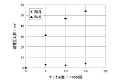
- FIG. 2 is a diagram showing the potential change of each electrode by the potential cycle test. As shown in FIG. 2, as a result of the potential cycle test on the anode electrode (anode), the voltage of the electrolytic cell increased by 3 mV in 5000 cycles, increased by 2 mV in 10000 cycles, and increased by 4 mV in 15000 cycles.
- the above-mentioned potential cycle test was carried out as a deterioration acceleration test on the cathode electrode of the electrolytic cell.
- an electrochemical evaluation device manufactured by Hokuto Denko Co., Ltd., HZ-7000 was used to determine the potential range from 0 to 1.6 V vs. with reference to the reference electrode.
- Potential cycle tests of 5000 cycles, 10000 cycles and 15000 cycles were carried out with RHE and a sweep rate of 1 V / sec.
- the entire electrolytic cell was kept at 40 ° C., a 1M sulfuric acid aqueous solution was circulated in the anode chamber at a flow velocity of 20 ccm, and toluene was circulated in the cathode chamber at a flow velocity of 20 ccm.
- the electrolysis test was carried out again at a current density of 0.2 A / cm 2 , and the amount of increase in overvoltage was measured using a data recording device (manufactured by Hioki Electric Co., Ltd., LR8400). The results are shown in FIG. As shown in FIG.
- the voltage of the electrolytic cell increased by 31 mV in 5000 cycles, increased by 47 mV in 10000 cycles, and increased by 54 mV in 15000 cycles.
- the electrode capacitance of each electrode used in the electrolytic cell was measured using an electrochemical evaluation device (HZ-7000, manufactured by Hokuto Denko Co., Ltd.). Specifically, a three-electrode electrolytic cell was prepared in which the working electrode was an anode electrode or a cathode electrode, the reference electrode was an Ag / AgCl electrode, and the counter electrode was a platinum wire. Moreover, a nitrogen degassed 1M sulfuric acid aqueous solution (normal temperature) was prepared as an electrolyte. Then, for the anode electrode, rated electrolysis was carried out for 5 minutes at a current density of 0.2 A / cm 2 to generate oxygen.
- HZ-7000 electrochemical evaluation device
- the anode electrode was reduced at a current density of ⁇ 0.5 mA / cm 2 , and the relationship between the amount of electricity and the potential was measured.
- rated electrolysis was carried out for 5 minutes at a current density of ⁇ 0.2 A / cm 2 to generate hydrogen.
- the cathode electrode was oxidized at a current density of 0.5 mA / cm 2 , and the relationship between the amount of electricity and the potential was measured. The results are shown in FIG.
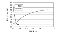
- FIG. 3 is a diagram showing the relationship between the amount of electricity and the potential of each electrode.
- FIG. 3 shows the electrode potential at each reduced electricity amount when the anode electrode (anode) is reduced by reverse current or cross leak, and the electrode potential at each reduced electricity amount when the cathode electrode (cathode) is oxidized. Shown.
- the amount of electricity when the potential of the anode electrode became the potential immediately after the electrolysis of the cathode electrode was stopped (potential of dissolved hydrogen: 0 V vs. RHE) was 0.11 C.
- the amount of electricity when the potential of the cathode electrode became the potential immediately after the electrolysis of the anode electrode was stopped was 1.0 C. That is, it was confirmed that the electrode capacitance of the anode electrode was 0.11C and the electrode capacitance of the cathode electrode was 1.0C.
- rated electrolysis and electrolysis stop control were performed according to the procedure shown below.
- the voltage of the electrolytic cell at this time was 1.6V.
- the electrolysis stop control first, the circulation of toluene to the cathode chamber was stopped, 50 minutes later, the supply of the electrolytic current from the power source was stopped, and 2 minutes later, the circulation of the sulfuric acid aqueous solution to the anode chamber was stopped.
- the cathode chamber was filled with hydrogen gas and the anode chamber was filled with an aqueous sulfuric acid solution.
- FIG. 4 is a diagram showing the potential change of each electrode when the control according to Example 1, Comparative Example 1 and Example 2 is performed.
- the potential of the anode electrode (anode) gradually decreased from the electrolysis stop (0 minutes), while the potential of the cathode electrode hardly changed.
- the voltage (cell voltage) of the electrolytic cell was 1.601 V, and the amount of increase in the voltage was 0.1 mV.
- Example 1 (Comparative Example 1) Using the same electrolytic cell used in Example 1, rated electrolysis was performed under the same conditions as in Example 1, and electrolysis stop control was performed according to the procedure shown below. That is, at the same time as the supply of the electrolytic current was stopped, the circulation of the aqueous sulfuric acid solution to the anode chamber and the circulation of the hydride to be hydrogenated to the cathode chamber were stopped. This stop order corresponds to the stop order in a conventional electrolytic cell.
- Example 2 Similar to Example 1, the potentials of both electrodes were measured when the electrolysis stop control was performed. The results are shown in FIG. As shown in FIG. 4, after the electrolysis was stopped (0 minutes), the potential of the cathode electrode (cathode) gradually increased, while the change in the potential of the anode electrode was small. Further, when the rated electrolysis was performed again after 8 hours had passed from the stop of the rated electrolysis, the voltage of the electrolytic cell was 1.601V and the amount of increase in the voltage was 1 mV.
- stepwise control to stop the circulation of the hydride to be hydrogenated to the cathode chamber and stop the electrolysis after a predetermined time elapses, and to the anode chamber after the electrolysis is stopped and the predetermined time elapses. It was confirmed that the potential fluctuation of the cathode electrode, which has a large deterioration rate, can be suppressed by the stepwise control of stopping the circulation of water, and thus the increase in the voltage of the electrolytic cell can be suppressed.
- the stepwise control of stopping the circulation of water to the anode chamber and stopping the electrolysis after a predetermined time has elapsed. It can also be understood that the potential fluctuation of the anode electrode having a large deterioration rate can be suppressed by the stepwise control of stopping the circulation of the hydride to be hydrogenated to the cathode chamber after stopping the electrolysis for a predetermined time. ..
- the control method of the present embodiment is to supply hydrogen to the cathode chamber 18 while the operation of the organic hydride generation system 1 is stopped when the deterioration rate d CA of the cathode electrode 16 is larger than the deterioration rate d AN of the anode electrode 12. including.
- d CA the deterioration rate of the cathode electrode 16
- d AN the deterioration rate of the anode electrode 12.
- the gas flow mechanism 40 described above is exemplified.
- the tank 42 contains hydrogen gas instead of the inert gas or oxidizing gas.
- the control unit 10 can switch between the flow and stop of the hydrogen gas from the tank 42 to the cathode chamber 18.
- the gas flow mechanism 48 described above is exemplified.
- the tank 50 contains oxygen gas instead of the inert gas or reducing gas.
- the control unit 10 can switch between the flow and stop of oxygen gas from the tank 50 to the anode chamber 14.
- the mechanism for supplying hydrogen to the cathode chamber 18 may be one in which hydrogen is dissolved in the cathode liquid to be distributed to the cathode chamber 18 and the cathode liquid is distributed to the cathode chamber 18 by the second distribution mechanism 8. ..
- the mechanism for supplying oxygen to the anode chamber 14 may be one in which oxygen is dissolved in the water flowing through the anode chamber 14 and this water is circulated to the anode chamber 14 by the first distribution mechanism 6.
- the supply of hydrogen to the cathode chamber 18 and the supply of oxygen to the anode chamber 14 may be continued from the stop of the operation of the organic hydride generation system 1 to the restart of the operation, or may be stopped after a lapse of a predetermined time. May be good.
- the present inventors have verified the effect obtained by the above-mentioned specific method 3 based on the following Example 2.
- Example 2 Using the same electrolytic cell used in Example 1, rated electrolysis and electrolysis stop control were performed according to the procedure shown below. First, rated electrolysis was carried out for 15 minutes at a current density of 0.2 A / cm 2 and an electrolytic cell temperature of 60 ° C. During electrolysis, a 1 M aqueous sulfuric acid solution was circulated in the anode chamber at a flow rate of 20 ccm. Toluene previously dissolved in hydrogen until it was saturated was circulated in the cathode chamber at a flow rate of 20 ccm. Subsequently, as an electrolysis stop control, the circulation of the sulfuric acid aqueous solution to the anode chamber was stopped 2 minutes after the rated electrolysis was stopped. Circulation of toluene to the cathode chamber continued.
- control unit 10 starts driving the second distribution mechanism 8 at the same time as or after the supply of the electrolytic current from the power supply 4 is started.
- the control unit 10 starts driving the second distribution mechanism 8 at the same time as or after the supply of the electrolytic current from the power supply 4 is started.
- the second distribution mechanism 8 stopped until the supply of the electrolytic current is started, it is possible to prevent the amount of hydrogen existing in the cathode chamber 18 from decreasing during the stop of the electrolysis.
- the negative charge amount on the cathode side is maintained to be larger than the positive charge amount on the anode side, and the potential fluctuation of the cathode electrode 16 which is liable to deteriorate is suppressed. Can be done.
- control method of the present embodiment is when the deterioration rate d AN of the anode electrode 12 is larger than the deterioration rate d CA of the cathode electrode 16 and the operation of the organic hydride generation system 1 is changed from the stopped operation to the start of the operation. This includes starting the flow of water to the anode chamber 14 after the start of supply of the electrolytic current.
- the control unit 10 starts driving the first distribution mechanism 6 at the same time as or after the supply of the electrolytic current from the power supply 4 is started. To do.
- the first distribution mechanism 6 By stopping the first distribution mechanism 6 until the supply of the electrolytic current is started, it is possible to prevent the amount of oxygen existing in the anode chamber 14 from decreasing during the stop of the electrolysis.
- the start of operation of the organic hydride generation system 1 the positive charge amount on the anode side is maintained in a state larger than the negative charge amount on the cathode side, and the potential fluctuation of the anode electrode 12 which is liable to deteriorate is suppressed. Can be done.
- the "starting distribution” means increasing the flow rate from the state in which the distribution is suppressed to a flow rate exceeding the flow rate.
- the volume of the cathode chamber 18 may be larger than the volume of the anode chamber 14. As a result, it is possible to maintain a state in which the amount of negative charge on the cathode side is larger than the amount of positive charge on the anode side.
- the volume of the anode chamber 14 may be larger than the volume of the cathode chamber 18. As a result, it is possible to maintain a state in which the positive charge amount on the anode side is sufficiently larger than the negative charge amount on the cathode side.
- the inside of the cathode chamber 18 may be pressurized when the operation of the organic hydride generation system 1 is stopped.
- the amount of substance of gaseous hydrogen existing in the cathode chamber 18 can be increased, and thus the state in which the negative charge amount on the cathode side is larger than the positive charge amount on the anode side can be maintained.
- This method can be realized, for example, by the organic hydride generation system 1 including the pressurizing mechanism of the cathode chamber 18 and the control unit 10 controlling the pressurizing mechanism.
- the anode chamber 14 may be pressurized when the operation of the organic hydride generation system 1 is stopped.
- the amount of substance of gaseous oxygen existing in the anode chamber 14 can be increased, and thus the state in which the positive charge amount on the anode side is larger than the negative charge amount on the cathode side can be maintained.
- This method can be realized, for example, by the organic hydride generation system 1 including the pressurizing mechanism of the anode chamber 14 and the control unit 10 controlling the pressurizing mechanism.
- the cathode electrode 16 when the cathode electrode 16 is more easily deteriorated than the anode electrode 12, the cathode electrode 16 may contain a material such as carbon that increases the electrode capacity. As a result, it is possible to maintain a state in which the amount of negative charge on the cathode side is larger than the amount of positive charge on the anode side.
- the anode electrode 12 when the anode electrode 12 is more likely to deteriorate than the cathode electrode 16, the anode electrode 12 may contain a material such as carbon that increases the electrode capacity. As a result, it is possible to maintain a state in which the amount of positive charge on the anode side is larger than the amount of negative charge on the cathode side.
- the specific methods described above can be combined as appropriate.
- the control method of the organic hydride generation system 1 is the anode electrode 12 and the cathode electrode 16 of the electrolytic tank 2, which have a large deterioration rate due to a potential change that occurs during operation stoppage.
- This includes controlling the potentials of the anode electrode 12 and the cathode electrode 16 so that the potential change of the above is smaller than the potential change of the electrode having a small deterioration rate.
- the durability of the organic hydride generation system 1 can be improved, and the organic hydride can be produced with low electric power for a longer period of time.
- the deterioration rate d CA of the cathode electrode 16 is obtained by subtracting the overvoltage component from the potential of the cathode electrode 16 at the time of rated electrolysis of the organic hydride generation system 1 and the potential of the anode electrode 12 at the time of rated electrolysis with respect to the cathode electrode 16. It is a value obtained by dividing the amount of change in voltage during rated electrolysis before and after the potential cycle test by the number of cycles when the potential cycle test in which the above potential is repeatedly applied is carried out. Thereby, the durability of the organic hydride generation system 1 can be improved.
- the charge amount of the anode electrode 12 is Q AN _electrode
- the charge amount of the cathode electrode 16 is Q CA _electrode
- the absolute value of the positive charge amount of the oxygen existing in the anode chamber 14 is Q AN _O 2
- the cathode chamber is Q AN _O 2
- the control method of this embodiment when the deterioration rate d CA is greater than the degradation rate d aN, Q aN _electrode + Q aN To maintain the state of _O 2 ⁇ Q CA _electrode + Q CA _H 2 or to maintain the state of Q AN _electrode + Q AN _O 2 > Q CA _electrode + Q CA _H 2 when the deterioration rate d AN is larger than the deterioration rate d CA. Including. Thereby, the durability of the organic hydride generation system 1 can be improved.
- the control method of the present embodiment when the deterioration rate d CA is larger than the deterioration rate d AN, when the operation is stopped, the flow of the hydride to the cathode chamber 18 is suppressed and a predetermined time elapses. After that, when the supply of the electrolytic current is stopped, or when the deterioration rate d AN is larger than the deterioration rate d CA and the operation is stopped, the supply of the electrolytic current is stopped and the cathode chamber 18 is reached after a predetermined time has elapsed. Includes suppressing the flow of hydrides. Thereby, the durability of the organic hydride generation system 1 can be improved.
- the control method of the present embodiment when the deterioration rate d CA is larger than the deterioration rate d AN, when the operation is stopped, the supply of the electrolytic current is stopped and the anode chamber 14 is reached after a predetermined time has elapsed.
- the flow of water is suppressed or the deterioration rate d AN is larger than the deterioration rate d CA, when the operation is stopped, the flow of water to the anode chamber 14 is suppressed and the electrolytic current elapses after a predetermined time has elapsed. Including stopping the supply of. Thereby, the durability of the organic hydride generation system 1 can be improved.
- the deterioration rate d CA when the deterioration rate d CA is larger than the deterioration rate d AN , an inert gas or a reducing gas is circulated in the anode chamber 14 during the operation stop, or the deterioration rate d AN is set.
- the deterioration rate when the deterioration rate is larger than d CA, it includes flowing an inert gas or an oxidizing gas through the cathode chamber 18 while the operation is stopped. Thereby, the durability of the organic hydride generation system 1 can be improved.
- the deterioration rate d CA when the deterioration rate d CA is larger than the deterioration rate d AN , hydrogen is supplied to the cathode chamber 18 during the operation stop, or the deterioration rate d AN is larger than the deterioration rate d CA. In some cases, it involves supplying oxygen to the anode chamber 14 during shutdown. Thereby, the durability of the organic hydride generation system 1 can be improved.
- the deterioration rate d CA is larger than the deterioration rate d AN
- the circulation of water to the anode chamber 14 is started after the supply of the electrolytic current is started.
- Embodiments may be specified by the items described below.
- [Item 1] Accommodates an anode electrode 12 for oxidizing water to generate protons, a cathode electrode 16 for hydrogenating a hydride with protons to generate an organic hydride, an anode chamber 14 accommodating an anode electrode 12, and a cathode electrode 16.
- the cathode chamber 18 and the electrolytic tank 2 having proton conductivity and having a diaphragm 20 for partitioning the anode chamber 14 and the cathode chamber 18
- a power supply 4 that supplies an electrolytic current to the electrolytic cell 2 and
- a control unit 10 for controlling the potentials of the anode electrode 12 and the cathode electrode 16 is provided.
- the anode electrode 12 has a degradation characteristic that the electrolytic current is deteriorated by a predetermined deterioration rate d AN by a potential change that occurs during the stop operation is not supplied to the electrolytic cell 2,
- the cathode electrode 16 has a deterioration characteristic of being deteriorated at a predetermined deterioration rate d CA due to a potential change that occurs during operation stoppage.
- the control unit 10 controls the potentials of the anode electrode 12 and the cathode electrode 16 so that the potential change of the electrode having a large deterioration rate among the anode electrode 12 and the cathode electrode 16 is smaller than the potential change of the electrode having a small deterioration rate.
- Organic hydride generation system 1 Organic hydride generation system 1.
- the present invention can be used in a control method for an organic hydride production system and an organic hydride production system.
- 1 organic hydride generation system 2 electrolytic cell, 4 power supply, 6 1st distribution mechanism, 8 2nd distribution mechanism, 10 control unit, 12 anode electrode, 14 anode chamber, 16 cathode electrode, 18 cathode chamber, 20 diaphragm.
Landscapes
- Chemical & Material Sciences (AREA)
- Organic Chemistry (AREA)
- Engineering & Computer Science (AREA)
- Chemical Kinetics & Catalysis (AREA)
- Electrochemistry (AREA)
- Materials Engineering (AREA)
- Metallurgy (AREA)
- Automation & Control Theory (AREA)
- Analytical Chemistry (AREA)
- Inorganic Chemistry (AREA)
- Electrolytic Production Of Non-Metals, Compounds, Apparatuses Therefor (AREA)
Abstract
Description
アノード(正極)での電極反応:2H2O→O2+4H++4e-
カソード(負極)での電極反応:TL+6H++6e-→MCH
カソードでの副反応:2H++2e-→H2
この副反応は、カソード電極16に供給される被水素化物の濃度が低下するにつれて、カソード電極16での電極反応に対する比率が増大する。副反応によって生成される水素ガスは、カソード室18を介して外部へ排出される。
電源4から電解槽2への電解電流の供給が停止して、有機ハイドライド生成システム1の運転が停止すると、隔膜20を介してガスのクロスオーバーが生じる場合がある。具体的には、アノード電極12で生じた酸素ガスの一部が、隔膜20を通過してカソード電極16側に移動する。また、カソード電極16において副反応で生じた水素ガスの一部が、隔膜20を通過してアノード電極12側に移動する。
電解停止後のアノードでの反応:O2+4H++4e-→2H2O
電解停止後のカソードでの反応:2H2→4H++4e-
なお、逆電流の発生においても、副反応で生じる水素ガスのみが還元剤として機能する。また、トルエン等の被水素化物はイオン伝導性がないため、アノード液の循環路のみがイオン伝導経路となる。
酸化剤の総量(電気量)=アノード電極の電極容量+反応電子数×ファラデー定数×電極室内酸素のモル数
還元剤の総量(電気量)=カソード電極の電極容量+反応電子数×ファラデー定数×電極室内水素のモル数
上記式において、酸素のモル数は、水に溶存する酸素とガス状態の酸素との合計のモル数である。同様に、水素のモル数は、カソード液に溶存する水素とガス状態の水素との合計のモル数である。
アノード電極12の電位が変化する確率と、カソード電極16の電位が変化する確率とは、通常は不明である。また、アノード電極12の還元劣化に対する耐性や、カソード電極16の酸化劣化に対する耐性は、含有する触媒の種類や量等により様々である。このため、各電極における、電解槽2の寿命到達までに要する電位変化の回数(以下では適宜、この回数を寿命回数という)は、一般的に大きな差がある。
有機ハイドライド生成システム1は、第2流通機構8によって運転中にカソード室18に被水素化物を流通させている。カソード室18に被水素化物を流通させると、これにともなってカソード室18内の有機ハイドライドや未反応の被水素化物だけでなく、副生水素も第2循環タンク32側に排出される。したがって、第2流通機構8は、カソード室18内の水素を排出する排出機構として機能する。
有機ハイドライド生成システム1は、第1流通機構6によって運転中にアノード室14に水を流通させている。アノード室14に水を流通させると、これにともなってアノード室14中の酸素が第1循環タンク26側に排出される。したがって、第1流通機構6は、アノード室14内の酸素を排出する排出機構として機能する。
まず、酸化イリジウム(IrO2)からなるアノード電極(幾何面積100cm2)、アノード室(容積40mL)、白金ルテニウム担持カーボン(Pt・Ru/C)からなるカソード電極(幾何面積100cm2)、カソード室(容積10mL)、カソード室中に挿入した参照極(標準水素電極)を備える電解槽を用意した。そして、この電解槽を用いて、0.2A/cm2の電流密度で電解試験を実施した。電解中、電解槽全体を60℃に保ち、アノード室に流速20ccmで1M硫酸水溶液を流通させ、カソード室に流速20ccmでトルエンを流通させた。このときのアノード電位は1.6V vs.RHE、カソード電位は0V vs.RHE、電解槽の電圧(セル電圧)は1.6Vであった。
実施例1で使用したものと同じ電解槽を用い、実施例1と同じ条件で定格電解を実施するとともに、以下に示す手順で電解停止制御を実施した。すなわち、電解電流の供給停止と同時に、アノード室への硫酸水溶液の循環とカソード室への被水素化物の循環とを停止した。この停止順序は、従来の電解槽における停止順序に相当する。
本実施の形態の制御方法は、カソード電極16の劣化率dCAがアノード電極12の劣化率dANより大きい場合に、有機ハイドライド生成システム1の運転停止中、カソード室18に水素を供給することを含む。これにより、カソード側の負の電荷量がアノード側の正の電荷量よりも多い状態を維持して、劣化しやすいカソード電極16の電位変動を抑制することができる。
実施例1で使用したものと同じ電解槽を用い、以下に示す手順で定格電解と電解停止制御を実施した。まず、電流密度0.2A/cm2、電解槽温度60℃で定格電解を15分間実施した。電解中、アノード室には、1M硫酸水溶液を流速20ccmで循環させた。カソード室には、予め水素を飽和するまで溶解させたトルエンを流速20ccmで循環させた。続いて電解停止制御として、定格電解を停止してから2分後にアノード室への硫酸水溶液の循環を停止した。カソード室へのトルエンの循環は継続した。
本実施の形態の制御方法は、カソード電極16の劣化率dCAがアノード電極12の劣化率dANより大きい場合に、有機ハイドライド生成システム1の運転停止中から運転開始に移行する際、電解電流の供給開始以降にカソード室18への被水素化物の流通を開始することを含む。
アノード電極12よりもカソード電極16の方が劣化しやすい場合、カソード室18の容積をアノード室14の容積よりも大きくしてもよい。これにより、カソード側の負の電荷量がアノード側の正の電荷量よりも多い状態を維持することができる。同様に、カソード電極16よりもアノード電極12の方が劣化しやすい場合、アノード室14の容積をカソード室18の容積よりも大きくしてもよい。これにより、アノード側の正の電荷量がカソード側の負の電荷量よりも十分多い状態を維持することができる。
[項目1]
水を酸化してプロトンを生成するためのアノード電極12、プロトンで被水素化物を水素化して有機ハイドライドを生成するためのカソード電極16、アノード電極12を収容するアノード室14、カソード電極16を収容するカソード室18、ならびにプロトン伝導性を有し、アノード室14およびカソード室18を仕切る隔膜20を有する電解槽2と、
電解槽2に電解電流を供給する電源4と、
アノード電極12およびカソード電極16の電位を制御する制御部10と、を備え、
アノード電極12は、電解電流が電解槽2に供給されない運転停止中に生じる電位変化によって所定の劣化率dANで劣化する劣化特性を有し、
カソード電極16は、運転停止中に生じる電位変化によって所定の劣化率dCAで劣化する劣化特性を有し、
制御部10は、アノード電極12およびカソード電極16のうち、劣化率の大きい電極の電位変化が劣化率の小さい電極の電位変化よりも小さくなるように、アノード電極12およびカソード電極16の電位を制御する有機ハイドライド生成システム1。
Claims (9)
- 有機ハイドライドを生成する電解槽と、前記電解槽に電解電流を供給する電源と、を備える有機ハイドライド生成システムの制御方法であって、
前記電解槽は、水を酸化してプロトンを生成するためのアノード電極、前記プロトンで被水素化物を水素化して有機ハイドライドを生成するためのカソード電極、前記アノード電極を収容するアノード室、前記カソード電極を収容するカソード室、ならびに前記アノード室および前記カソード室を仕切る隔膜を有し、
前記アノード電極は、前記電解電流が前記電解槽に供給されない運転停止中に生じる電位変化によって所定の劣化率dANで劣化する劣化特性を有し、
前記カソード電極は、前記運転停止中に生じる電位変化によって所定の劣化率dCAで劣化する劣化特性を有し、
前記制御方法は、前記アノード電極および前記カソード電極のうち、前記劣化率の大きい電極の前記電位変化が前記劣化率の小さい電極の前記電位変化よりも小さくなるように、前記アノード電極および前記カソード電極の電位を制御することを含む有機ハイドライド生成システムの制御方法。 - 前記劣化率dANは、前記アノード電極に対して、前記有機ハイドライド生成システムの定格電解時における前記アノード電極の電位と、前記定格電解時における前記カソード電極の電位から過電圧分を減じた電位とを繰り返し印加する電位サイクル試験が実施された場合における、当該電位サイクル試験前後での前記定格電解時の電圧の変化量をサイクル回数で除した値であり、
前記劣化率dCAは、前記カソード電極に対して、前記定格電解時における前記カソード電極の電位と、前記定格電解時における前記アノード電極の電位から過電圧分を減じた電位とを繰り返し印加する電位サイクル試験が実施された場合における、当該電位サイクル試験前後での前記定格電解時の電圧の変化量をサイクル回数で除した値である請求項1に記載の有機ハイドライド生成システムの制御方法。 - 前記アノード電極が有する電荷量をQAN_electrode、
前記カソード電極が有する電荷量をQCA_electrode、
前記アノード室に存在する酸素が有する正の電荷量の絶対値をQAN_O2、
前記カソード室に存在する水素が有する負の電荷量の絶対値をQCA_H2とするとき、
前記劣化率dCAが前記劣化率dANより大きい場合に、
QAN_electrode+QAN_O2<QCA_electrode+QCA_H2の状態を維持するか、
前記劣化率dANが前記劣化率dCAより大きい場合に、
QAN_electrode+QAN_O2>QCA_electrode+QCA_H2の状態を維持することを含む請求項1または2に記載の有機ハイドライド生成システムの制御方法。 - 前記有機ハイドライド生成システムは、運転中に前記カソード室に前記被水素化物を流通させており、
前記制御方法は、前記劣化率dCAが前記劣化率dANより大きい場合に、前記運転停止に移行する際、前記流通を抑制して所定時間が経過した後に前記電解電流の供給を停止するか、
前記劣化率dANが前記劣化率dCAより大きい場合に、前記運転停止に移行する際、前記電解電流の供給を停止して所定時間が経過した後に前記流通を抑制することを含む請求項1乃至3のいずれか1項に記載の有機ハイドライド生成システムの制御方法。 - 前記有機ハイドライド生成システムは、運転中に前記アノード室に水を流通させており、
前記制御方法は、前記劣化率dCAが前記劣化率dANより大きい場合に、前記運転停止に移行する際、前記電解電流の供給を停止して所定時間が経過した後に前記流通を抑制するか、
前記劣化率dANが前記劣化率dCAより大きい場合に、前記運転停止に移行する際、前記流通を抑制して所定時間が経過した後に前記電解電流の供給を停止することを含む請求項1乃至4のいずれか1項に記載の有機ハイドライド生成システムの制御方法。 - 前記劣化率dCAが前記劣化率dANより大きい場合に、前記運転停止中、前記アノード室に不活性ガスあるいは還元性ガスを流通させるか、
前記劣化率dANが前記劣化率dCAより大きい場合に、前記運転停止中、前記カソード室に不活性ガスあるいは酸化性ガスを流通させることを含む請求項1乃至5のいずれか1項に記載の有機ハイドライド生成システムの制御方法。 - 前記劣化率dCAが前記劣化率dANより大きい場合に、前記運転停止中、前記カソード室に水素を供給するか、
前記劣化率dANが前記劣化率dCAより大きい場合に、前記運転停止中、前記アノード室に酸素を供給することを含む請求項1乃至6のいずれか1項に記載の有機ハイドライド生成システムの制御方法。 - 前記有機ハイドライド生成システムは、運転中に前記カソード室に前記被水素化物を流通させ、前記アノード室に水を流通させており、
前記制御方法は、前記劣化率dCAが前記劣化率dANより大きい場合に、前記運転停止中から運転を開始する際、前記電解電流の供給開始以降に前記カソード室への被水素化物の流通を開始するか、
前記劣化率dANが前記劣化率dCAより大きい場合に、前記運転停止中から運転を開始する際、前記電解電流の供給開始以降に前記アノード室への水の流通を開始することを含む請求項1乃至7のいずれか1項に記載の有機ハイドライド生成システムの制御方法。 - 水を酸化してプロトンを生成するためのアノード電極、前記プロトンで被水素化物を水素化して有機ハイドライドを生成するためのカソード電極、前記アノード電極を収容するアノード室、前記カソード電極を収容するカソード室、ならびに前記アノード室および前記カソード室を仕切る隔膜を有する電解槽と、
前記電解槽に電解電流を供給する電源と、
前記アノード電極および前記カソード電極の電位を制御する制御部と、を備え、
前記アノード電極は、前記電解電流が前記電解槽に供給されない運転停止中に生じる電位変化によって所定の劣化率dANで劣化する劣化特性を有し、
前記カソード電極は、前記運転停止中に生じる電位変化によって所定の劣化率dCAで劣化する劣化特性を有し、
前記制御部は、前記アノード電極および前記カソード電極のうち、前記劣化率の大きい電極の前記電位変化が前記劣化率の小さい電極の前記電位変化よりも小さくなるように、前記アノード電極および前記カソード電極の電位を制御する有機ハイドライド生成システム。
Priority Applications (5)
| Application Number | Priority Date | Filing Date | Title |
|---|---|---|---|
| US17/637,505 US12252798B2 (en) | 2019-09-20 | 2020-09-18 | Method for controlling organic hydride generation system, and organic hydride generation system |
| AU2020349264A AU2020349264B2 (en) | 2019-09-20 | 2020-09-18 | Method for controlling organic hydride generation system, and organic hydride generation system |
| EP20866223.9A EP4033010A4 (en) | 2019-09-20 | 2020-09-18 | Method for controlling an organic hydrogen production system and system for producing organic hydrogens |
| CN202080035388.2A CN113853455B (zh) | 2019-09-20 | 2020-09-18 | 有机氢化物生成系统的控制方法和有机氢化物生成系统 |
| US19/049,200 US20250179660A1 (en) | 2019-09-20 | 2025-02-10 | Method for controlling organic hydride generation system, and organic hydride generation system |
Applications Claiming Priority (2)
| Application Number | Priority Date | Filing Date | Title |
|---|---|---|---|
| JP2019-171594 | 2019-09-20 | ||
| JP2019171594A JP7372797B2 (ja) | 2019-09-20 | 2019-09-20 | 有機ハイドライド生成システム、および有機ハイドライド生成システムの制御方法 |
Related Child Applications (2)
| Application Number | Title | Priority Date | Filing Date |
|---|---|---|---|
| US17/637,505 A-371-Of-International US12252798B2 (en) | 2019-09-20 | 2020-09-18 | Method for controlling organic hydride generation system, and organic hydride generation system |
| US19/049,200 Continuation US20250179660A1 (en) | 2019-09-20 | 2025-02-10 | Method for controlling organic hydride generation system, and organic hydride generation system |
Publications (1)
| Publication Number | Publication Date |
|---|---|
| WO2021054445A1 true WO2021054445A1 (ja) | 2021-03-25 |
Family
ID=74877873
Family Applications (1)
| Application Number | Title | Priority Date | Filing Date |
|---|---|---|---|
| PCT/JP2020/035488 Ceased WO2021054445A1 (ja) | 2019-09-20 | 2020-09-18 | 有機ハイドライド生成システムの制御方法および有機ハイドライド生成システム |
Country Status (6)
| Country | Link |
|---|---|
| US (2) | US12252798B2 (ja) |
| EP (1) | EP4033010A4 (ja) |
| JP (1) | JP7372797B2 (ja) |
| CN (1) | CN113853455B (ja) |
| AU (1) | AU2020349264B2 (ja) |
| WO (1) | WO2021054445A1 (ja) |
Cited By (1)
| Publication number | Priority date | Publication date | Assignee | Title |
|---|---|---|---|---|
| WO2024219065A1 (ja) * | 2023-04-19 | 2024-10-24 | Eneos株式会社 | 有機ハイドライド製造装置および有機ハイドライド製造方法 |
Families Citing this family (2)
| Publication number | Priority date | Publication date | Assignee | Title |
|---|---|---|---|---|
| JP7693476B2 (ja) * | 2021-09-13 | 2025-06-17 | Agcエンジニアリング株式会社 | イオン交換膜及び触媒層付きイオン交換膜の製造方法 |
| CN117026260B (zh) * | 2023-10-08 | 2024-09-20 | 陕西氢易能源科技有限公司 | 一种电化学加氢的pem反应器及其系统 |
Citations (8)
| Publication number | Priority date | Publication date | Assignee | Title |
|---|---|---|---|---|
| WO2012043085A1 (ja) * | 2010-09-30 | 2012-04-05 | 株式会社日立製作所 | 水素製造システム |
| WO2012091128A1 (ja) | 2010-12-28 | 2012-07-05 | Jx日鉱日石エネルギー株式会社 | 有機化合物の水素化装置及び水素化方法 |
| JP2014091838A (ja) * | 2012-10-31 | 2014-05-19 | Chlorine Engineers Corp Ltd | イオン交換膜電解槽の逆電流防止方法 |
| JP2017179601A (ja) * | 2016-03-23 | 2017-10-05 | Jxtgエネルギー株式会社 | 電解セル用セパレータ、電解セル、電気化学還元装置及び芳香族炭化水素化合物の水素化体の製造方法 |
| JP2017206731A (ja) * | 2016-05-17 | 2017-11-24 | 旭化成株式会社 | アルカリ水電解システム |
| JP2019019379A (ja) * | 2017-07-18 | 2019-02-07 | Jxtgエネルギー株式会社 | 電気化学デバイス |
| JP2019099905A (ja) * | 2017-11-30 | 2019-06-24 | 株式会社豊田中央研究所 | 電解システム |
| JP2019151876A (ja) * | 2018-03-01 | 2019-09-12 | Jxtgエネルギー株式会社 | 有機ハイドライド製造装置、有機ハイドライドの製造方法およびエネルギー輸送方法 |
Family Cites Families (2)
| Publication number | Priority date | Publication date | Assignee | Title |
|---|---|---|---|---|
| CN104471114A (zh) * | 2012-07-03 | 2015-03-25 | 吉坤日矿日石能源株式会社 | 电化学还原装置和芳香烃化合物或含氮杂环芳香族化合物的氢化物的制备方法 |
| JP6501141B2 (ja) * | 2014-11-21 | 2019-04-17 | 国立大学法人横浜国立大学 | 有機ハイドライド製造装置およびこれを用いた有機ハイドライドの製造方法 |
-
2019
- 2019-09-20 JP JP2019171594A patent/JP7372797B2/ja active Active
-
2020
- 2020-09-18 WO PCT/JP2020/035488 patent/WO2021054445A1/ja not_active Ceased
- 2020-09-18 EP EP20866223.9A patent/EP4033010A4/en active Pending
- 2020-09-18 US US17/637,505 patent/US12252798B2/en active Active
- 2020-09-18 CN CN202080035388.2A patent/CN113853455B/zh active Active
- 2020-09-18 AU AU2020349264A patent/AU2020349264B2/en active Active
-
2025
- 2025-02-10 US US19/049,200 patent/US20250179660A1/en active Pending
Patent Citations (8)
| Publication number | Priority date | Publication date | Assignee | Title |
|---|---|---|---|---|
| WO2012043085A1 (ja) * | 2010-09-30 | 2012-04-05 | 株式会社日立製作所 | 水素製造システム |
| WO2012091128A1 (ja) | 2010-12-28 | 2012-07-05 | Jx日鉱日石エネルギー株式会社 | 有機化合物の水素化装置及び水素化方法 |
| JP2014091838A (ja) * | 2012-10-31 | 2014-05-19 | Chlorine Engineers Corp Ltd | イオン交換膜電解槽の逆電流防止方法 |
| JP2017179601A (ja) * | 2016-03-23 | 2017-10-05 | Jxtgエネルギー株式会社 | 電解セル用セパレータ、電解セル、電気化学還元装置及び芳香族炭化水素化合物の水素化体の製造方法 |
| JP2017206731A (ja) * | 2016-05-17 | 2017-11-24 | 旭化成株式会社 | アルカリ水電解システム |
| JP2019019379A (ja) * | 2017-07-18 | 2019-02-07 | Jxtgエネルギー株式会社 | 電気化学デバイス |
| JP2019099905A (ja) * | 2017-11-30 | 2019-06-24 | 株式会社豊田中央研究所 | 電解システム |
| JP2019151876A (ja) * | 2018-03-01 | 2019-09-12 | Jxtgエネルギー株式会社 | 有機ハイドライド製造装置、有機ハイドライドの製造方法およびエネルギー輸送方法 |
Non-Patent Citations (1)
| Title |
|---|
| See also references of EP4033010A4 |
Cited By (1)
| Publication number | Priority date | Publication date | Assignee | Title |
|---|---|---|---|---|
| WO2024219065A1 (ja) * | 2023-04-19 | 2024-10-24 | Eneos株式会社 | 有機ハイドライド製造装置および有機ハイドライド製造方法 |
Also Published As
| Publication number | Publication date |
|---|---|
| CN113853455A (zh) | 2021-12-28 |
| US12252798B2 (en) | 2025-03-18 |
| US20220290314A1 (en) | 2022-09-15 |
| CN113853455B (zh) | 2023-10-03 |
| EP4033010A1 (en) | 2022-07-27 |
| AU2020349264B2 (en) | 2023-05-25 |
| JP7372797B2 (ja) | 2023-11-01 |
| AU2020349264A1 (en) | 2022-03-31 |
| EP4033010A4 (en) | 2025-04-30 |
| JP2021046601A (ja) | 2021-03-25 |
| US20250179660A1 (en) | 2025-06-05 |
Similar Documents
| Publication | Publication Date | Title |
|---|---|---|
| JP7381008B2 (ja) | 水素発生システムの制御方法、および水素発生システム | |
| JP7429919B2 (ja) | 水素発生システム、水素発生システムの制御装置および水素発生システムの制御方法 | |
| US20250179660A1 (en) | Method for controlling organic hydride generation system, and organic hydride generation system | |
| US20250263853A1 (en) | Organic hydride generation system, control device for organic hydride generation system, and control method for organic hydride generation system | |
| JP7036316B2 (ja) | 電気化学デバイスおよび電気化学デバイスの制御方法 | |
| WO2013111586A1 (ja) | 電気化学還元装置および、芳香族炭化水素化合物または含窒素複素環式芳香族化合物の水素化体の製造方法 | |
| US10301177B2 (en) | Hydrogen desorption method and dehydrogenation apparatus | |
| US20250207266A1 (en) | Control device for water electrolysis cell, water electrolysis system, and control method for water electrolysis cell | |
| AU2023241755A1 (en) | Control device for water electrolysis cell, water electrolysis system, and method for controlling water electrolysis cell | |
| WO2025239367A1 (ja) | 有機ハイドライド製造装置、制御装置及び有機ハイドライド製造システム | |
| JP2018119205A (ja) | 脱水素方法、水素供給溶液及び脱水素装置 | |
| JP7038375B2 (ja) | 電気化学デバイスおよび電気化学デバイスの制御方法 | |
| CN116547233A (zh) | 有机氢化物制造系统、有机氢化物制造系统的控制装置以及有机氢化物制造系统的控制方法 |
Legal Events
| Date | Code | Title | Description |
|---|---|---|---|
| 121 | Ep: the epo has been informed by wipo that ep was designated in this application |
Ref document number: 20866223 Country of ref document: EP Kind code of ref document: A1 |
|
| NENP | Non-entry into the national phase |
Ref country code: DE |
|
| ENP | Entry into the national phase |
Ref document number: 2020349264 Country of ref document: AU Date of ref document: 20200918 Kind code of ref document: A |
|
| ENP | Entry into the national phase |
Ref document number: 2020866223 Country of ref document: EP Effective date: 20220420 |
|
| WWG | Wipo information: grant in national office |
Ref document number: 17637505 Country of ref document: US |