WO2021054755A1 - 안테나 장치 - Google Patents
안테나 장치 Download PDFInfo
- Publication number
- WO2021054755A1 WO2021054755A1 PCT/KR2020/012602 KR2020012602W WO2021054755A1 WO 2021054755 A1 WO2021054755 A1 WO 2021054755A1 KR 2020012602 W KR2020012602 W KR 2020012602W WO 2021054755 A1 WO2021054755 A1 WO 2021054755A1
- Authority
- WO
- WIPO (PCT)
- Prior art keywords
- heat
- heat dissipation
- cluster
- antenna device
- main housing
- Prior art date
- Legal status (The legal status is an assumption and is not a legal conclusion. Google has not performed a legal analysis and makes no representation as to the accuracy of the status listed.)
- Ceased
Links
Images


Classifications
-
- H—ELECTRICITY
- H01—ELECTRIC ELEMENTS
- H01Q—ANTENNAS, i.e. RADIO AERIALS
- H01Q1/00—Details of, or arrangements associated with, antennas
- H01Q1/02—Arrangements for de-icing; Arrangements for drying-out ; Arrangements for cooling; Arrangements for preventing corrosion
-
- F—MECHANICAL ENGINEERING; LIGHTING; HEATING; WEAPONS; BLASTING
- F28—HEAT EXCHANGE IN GENERAL
- F28D—HEAT-EXCHANGE APPARATUS, NOT PROVIDED FOR IN ANOTHER SUBCLASS, IN WHICH THE HEAT-EXCHANGE MEDIA DO NOT COME INTO DIRECT CONTACT
- F28D15/00—Heat-exchange apparatus with the intermediate heat-transfer medium in closed tubes passing into or through the conduit walls ; Heat-exchange apparatus employing intermediate heat-transfer medium or bodies
- F28D15/02—Heat-exchange apparatus with the intermediate heat-transfer medium in closed tubes passing into or through the conduit walls ; Heat-exchange apparatus employing intermediate heat-transfer medium or bodies in which the medium condenses and evaporates, e.g. heat pipes
- F28D15/0233—Heat-exchange apparatus with the intermediate heat-transfer medium in closed tubes passing into or through the conduit walls ; Heat-exchange apparatus employing intermediate heat-transfer medium or bodies in which the medium condenses and evaporates, e.g. heat pipes the conduits having a particular shape, e.g. non-circular cross-section, annular
-
- F—MECHANICAL ENGINEERING; LIGHTING; HEATING; WEAPONS; BLASTING
- F28—HEAT EXCHANGE IN GENERAL
- F28F—DETAILS OF HEAT-EXCHANGE AND HEAT-TRANSFER APPARATUS, OF GENERAL APPLICATION
- F28F3/00—Plate-like or laminated elements; Assemblies of plate-like or laminated elements
- F28F3/12—Elements constructed in the shape of a hollow panel, e.g. with channels
-
- H—ELECTRICITY
- H01—ELECTRIC ELEMENTS
- H01Q—ANTENNAS, i.e. RADIO AERIALS
- H01Q1/00—Details of, or arrangements associated with, antennas
- H01Q1/12—Supports; Mounting means
- H01Q1/22—Supports; Mounting means by structural association with other equipment or articles
- H01Q1/2283—Supports; Mounting means by structural association with other equipment or articles mounted in or on the surface of a semiconductor substrate as a chip-type antenna or integrated with other components into an IC package
-
- H—ELECTRICITY
- H01—ELECTRIC ELEMENTS
- H01Q—ANTENNAS, i.e. RADIO AERIALS
- H01Q1/00—Details of, or arrangements associated with, antennas
- H01Q1/12—Supports; Mounting means
- H01Q1/22—Supports; Mounting means by structural association with other equipment or articles
- H01Q1/24—Supports; Mounting means by structural association with other equipment or articles with receiving set
- H01Q1/241—Supports; Mounting means by structural association with other equipment or articles with receiving set used in mobile communications, e.g. GSM
- H01Q1/246—Supports; Mounting means by structural association with other equipment or articles with receiving set used in mobile communications, e.g. GSM specially adapted for base stations
-
- H—ELECTRICITY
- H01—ELECTRIC ELEMENTS
- H01Q—ANTENNAS, i.e. RADIO AERIALS
- H01Q1/00—Details of, or arrangements associated with, antennas
- H01Q1/42—Housings not intimately mechanically associated with radiating elements, e.g. radome
-
- H—ELECTRICITY
- H01—ELECTRIC ELEMENTS
- H01Q—ANTENNAS, i.e. RADIO AERIALS
- H01Q21/00—Antenna arrays or systems
- H01Q21/0006—Particular feeding systems
- H01Q21/0025—Modular arrays
-
- H—ELECTRICITY
- H05—ELECTRIC TECHNIQUES NOT OTHERWISE PROVIDED FOR
- H05K—PRINTED CIRCUITS; CASINGS OR CONSTRUCTIONAL DETAILS OF ELECTRIC APPARATUS; MANUFACTURE OF ASSEMBLAGES OF ELECTRICAL COMPONENTS
- H05K7/00—Constructional details common to different types of electric apparatus
- H05K7/20—Modifications to facilitate cooling, ventilating, or heating
- H05K7/20009—Modifications to facilitate cooling, ventilating, or heating using a gaseous coolant in electronic enclosures
- H05K7/20127—Natural convection
-
- H—ELECTRICITY
- H05—ELECTRIC TECHNIQUES NOT OTHERWISE PROVIDED FOR
- H05K—PRINTED CIRCUITS; CASINGS OR CONSTRUCTIONAL DETAILS OF ELECTRIC APPARATUS; MANUFACTURE OF ASSEMBLAGES OF ELECTRICAL COMPONENTS
- H05K7/00—Constructional details common to different types of electric apparatus
- H05K7/20—Modifications to facilitate cooling, ventilating, or heating
- H05K7/2029—Modifications to facilitate cooling, ventilating, or heating using a liquid coolant with phase change in electronic enclosures
- H05K7/20336—Heat pipes, e.g. wicks or capillary pumps
-
- F—MECHANICAL ENGINEERING; LIGHTING; HEATING; WEAPONS; BLASTING
- F28—HEAT EXCHANGE IN GENERAL
- F28D—HEAT-EXCHANGE APPARATUS, NOT PROVIDED FOR IN ANOTHER SUBCLASS, IN WHICH THE HEAT-EXCHANGE MEDIA DO NOT COME INTO DIRECT CONTACT
- F28D21/00—Heat-exchange apparatus not covered by any of the groups F28D1/00 - F28D20/00
- F28D2021/0019—Other heat exchangers for particular applications; Heat exchange systems not otherwise provided for
- F28D2021/0028—Other heat exchangers for particular applications; Heat exchange systems not otherwise provided for for cooling heat generating elements, e.g. for cooling electronic components or electric devices
- F28D2021/0029—Heat sinks
Definitions
- the present invention relates to an antenna device (ANTENNA APPARATUS), and more particularly, to an antenna device that suppresses the heat concentration phenomenon due to the formation of a rising airflow of heat generated from the heating elements as much as possible, and induces rapid heat dissipation from the heat source to the rear. will be.
- Wireless communication technology for example, MIMO (Multiple-Input Multiple-Output) technology
- MIMO Multiple-Input Multiple-Output
- a transmitter transmits different data through each transmission antenna.
- the receiver it is a spatial multiplexing technique that separates transmission data through appropriate signal processing.
- the channel capacity increases, thereby enabling more data to be transmitted.
- a channel capacity of about 10 times is secured by using the same frequency band compared to the current single antenna system.
- the number of transmitters and filters also increases.
- the heating element is also increased, and the MIMO technology is a research on a heat dissipation structure that effectively dissipates heat generated from a plurality of heating elements in order to prevent performance degradation of the antenna device. Preceded.
- a plurality of heating elements are disposed vertically in order to avoid the problem of an increase in the number of parts and interference between the parts, and the overall external shape is also arranged vertically, and the heating element in the lower part There is a problem in that the heat generated from the field is concentrated on the upper side, preventing the maintenance of uniform antenna performance.
- An object of the present invention is to provide an antenna device with improved heat dissipation performance.
- Another object of the present invention is to provide an independent U-shaped heat dissipation cluster and an intermediate heat dissipation cluster corresponding to heat dissipation of heating elements of the same specifications and specifications, but the heat concentration phenomenon due to the rising airflow of heat can be minimized. It is to provide an antenna device.
- another object of the present invention is to provide an antenna device that prevents deterioration of the performance of the heating elements by increasing the heat dissipation performance emitted through the rear surface of the main housing.
- An embodiment of an antenna device includes a main housing for receiving and fixing a first substrate on which a plurality of heating elements are mounted on a rear surface; It is detachably coupled to the rear side of the main housing and is filled with a predetermined refrigerant, but the refrigerant receives heat from the heating elements and moves to the outside along a pattern flow path formed to disperse and flow to the outside. At least one U-shaped heat dissipation cluster that radiates heat; And at least one heat-collecting medium fixing part for collecting and transferring heat from the heating elements to the Yu-shaped heat dissipating cluster while mediating the attachment and detachment of the U-shaped heat dissipation cluster to the rear surface of the main housing.
- the U-shaped heat dissipation cluster may include a lower heat dissipation part provided at a lower side of the rear side of the main housing and an upper heat dissipation part provided at an upper part of the rear side of the main housing.
- the plurality of heating elements include a first heating element and a second heating element
- the first heating element P is a power amplifier (PA) element
- the second heating element S is for RFIC. It may be a semiconductor device or a low noise amplifier (LNA) device.
- PA power amplifier
- LNA low noise amplifier
- it may further include an intermediate heat dissipation cluster for dissipating heat generated from a plurality of third heating elements mounted on the rear side of the first substrate between the lower heat dissipation part and the upper heat dissipation part.
- the intermediate heat dissipation cluster is installed at a heat generating portion of the third heating element to absorb and collect heat from the third heating element, and one end is in thermal contact with the heat collecting unit, and the other end is in the main housing. It may include a heat transfer unit provided with a heat pipe in thermal contact with the mounting combined heat radiating unit provided on the rear side of the.
- the amount of heat generated by the plurality of third heating elements may be at least greater than the amount of heat generated by the plurality of heating elements.
- the U-shaped heat dissipation cluster is bent to have a U-shaped cross section, and is bent so as to have an inner heat sink and a U-shaped cross section in which the pattern flow path is embossed inward so that the refrigerant is filled, It may include an outer heat sink bonded to the outside of the inner heat sink.
- the inner heat sink and the outer heat sink may be closed-joined so that the refrigerant filled in the pattern flow path does not leak.
- the pattern flow path is provided at a connection portion of the U-shaped cross section, is formed to be in communication with the heat receiving pattern portion and the heat receiving pattern portion receiving heat from the heat-collecting medium fixing portion, and the heat It may include heat dissipation pattern portions respectively formed at both ends of the U-shaped cross-section to dissipate heat transmitted from the receiving pattern portion.
- the heat-receiving pattern portion is formed in a plurality of straight lines to interconnect the heat dissipation pattern portions respectively formed at both ends of the U-shaped cross-section, and the heat dissipation pattern portion comprises the plurality of rows formed in the plurality of straight lines. It is all in communication with the front end of the receiving pattern portion, it may be formed to increase the heat dissipation area toward the outside.
- the heat dissipation pattern part, the inner heat sink and the outer heat sink are bonded to each other, a bonding surface that is bonded to each other in a circular or polygonal shape, and the inner radiating plate and the outer radiating plate are spaced apart from each other, and between the bonding surfaces or outside the bonding surface, the It may include a refrigerant flow path through which the refrigerant flows.
- the heat-collecting medium fixing part may have a U-shaped fitting groove to accommodate a part of the heat-receiving pattern part.
- the U-shaped heat dissipation cluster may be provided as a plurality of unit heat dissipation bodies having a U-shaped cross section having a gap distance (Gaps) and a height (Height) in which mutual thermal boundary layers do not interfere.
- the antenna device while effectively radiating heat through an independent U-shaped heat dissipation cluster and an intermediate heat dissipation cluster for each of the heating elements, heat rising from the rear surface of the main housing formed vertically By minimizing the heat concentration phenomenon, it has the effect of preventing the occurrence of deterioration in the performance of parts.
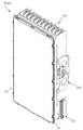
- FIG. 1A and 1B are perspective views showing the front and rear appearances of an antenna device according to an embodiment of the present invention.
- Figure 2 is an exploded perspective view of Figure 1a
- FIG. 3 is an exploded perspective view of FIG. 1B
- FIG. 4 is an exploded perspective view showing a coupling relationship between a main housing and a second substrate in the configuration of FIG. 2,
- 5A and 5B are a front exploded perspective view and a rear exploded perspective view showing an installation state of the intermediate heat dissipation cluster on the rear surface of the main housing in the configuration of FIG. 2;
- FIG. 6 is a cross-sectional view and a partial enlarged view of the antenna device according to an embodiment of the present invention
- FIG. 7 is a perspective view showing a unit heat sink in the configuration of an antenna device according to an embodiment of the present invention.
- FIG. 8 is an exploded view of an inner heat sink in the configuration of FIG. 7,
- FIG. 9 is an exploded perspective view of FIG. 7,
- FIG. 10 is a cut-away perspective view taken along line A-A of FIG. 7,
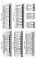
- FIG. 11 is a cross-sectional view and a rear view showing an arrangement relationship of a plurality of heating elements and a plurality of U-shaped heat dissipation clusters for proving the effect of the antenna device according to an embodiment of the present invention
- FIG. 12 is an enlarged view of an enlarged portion "B" of FIG. 11;
- FIG. 13 is a simulation diagram showing a heat dissipation speed by a heat-collecting medium fixing part in the configuration of an antenna device according to an embodiment of the present invention
- FIG. 14 is a simulation diagram showing a state of heat transfer by a heat collecting medium fixing part in the configuration of an antenna device according to an embodiment of the present invention.
- FIG. 15 is a heat transfer simulation diagram for designing an optimal height of a unit heat sink in the configuration of an antenna device according to an embodiment of the present invention
- 16 is a heat transfer simulation diagram for designing an optimal gap distance of a unit heat sink in the configuration of an antenna device according to an embodiment of the present invention.
- antenna device 10 radome
- main housing 21 second substrate
- antenna element 23 first substrate
- PSU element 100 U-shaped heat dissipation cluster
- heat receiving pattern portion 110 upper radiating portion
- intermediate heat dissipation cluster 241 heat collecting unit
- heat transfer unit P first heating element(s)
- FIG. 1A and 1B are perspective views showing the front and rear appearances of an antenna device according to an embodiment of the present invention
- FIG. 2 is an exploded perspective view of FIG. 1A
- FIG. 3 is an exploded perspective view of FIG. 1B
- FIG. 4 2 is an exploded perspective view showing a coupling relationship between a main housing and a second substrate.
- the antenna device 1 has a rectangular shape having a front-to-back receiving width and a long and thin front-to-back receiving width, forming an accommodation space that is opened forward, as shown in FIGS. 1A to 3.
- the formed main housing 20 and a clamshell 28 as a substrate for a PAU (Power Amplifier Unit) and DTU (Digital Transceving Unit) accommodated inside the accommodation space of the main housing 20
- a plurality of MBF (Multi Band filter) elements 24 are mounted on the front surface, and a plurality of first heating elements (P), a plurality of second heating elements (S), and a plurality of third heating elements (F)
- a first substrate 23 mounted on the rear surface and a second substrate 21 on which a plurality of antenna elements 22 are mounted.
- the first substrate 23 may be referred to as a main board, and the second substrate 21 may be referred to as an antenna board.
- the first heating element P and the second heating element S are elements having different output power, and the first heating element P is a power amplifier (PA) element, and the second heating element S is a semiconductor for RFIC. It may be a device or a low noise amplifier (LNA) device.
- the first heating element (P), the PA element is a transistor that is the main heating component of the high-frequency power amplifier, and is an RF element with high output power, compared to the second heating element (S), a semiconductor element for RFIC or a low noise amplifier (LNA) element.
- the calorific value is large.
- the first heating element P which has a higher calorific value than the second heating element S, can be designed to be disposed closer to the thermal contact portion 29 of the main housing 20 to be described later than the second heating element S. , Accordingly, the heat generated from the first heating element P is easily heat-conducted through direct surface thermal contact with the thermal contact portion 29, and through the U-shaped heat dissipation cluster 100 installed on the rear side of the main housing 20. Can be heat dissipated.
- the antenna device 1 shields the receiving space of the main housing 20, but is provided with a material through which electromagnetic waves pass, and is fixed to the front side of the main housing 20; , A U-shaped heat dissipation cluster 100 that is detachably provided at the rear of the main housing 20 to dissipate heat generated from the first and second heating elements P and S described above to the outside. It may contain more.
- a power supply unit including a PSU housing 31 provided to be separated from the first substrate 23 and the second substrate 21 described above and detachably installed on the rear side of the main housing 20 may be further included.
- I can. Inside the PSU housing 31, a plurality of PSU (power supply unit) elements 34 that substantially supply power to the above-described first heating elements P to third heating elements F are mounted.
- the PSU substrate 33 is embedded, and a plurality of PSU radiating fins 32 may be provided on the outside of the PSU housing 31 and independently radiate heat generated from the plurality of PSU elements 34.
- the PSU housing 31 may further include a PSU cover 35 for partitioning a boundary with the main housing 20 while shielding the PSU accommodation space in which the PSU substrate 33 is embedded.
- component elements such as the antenna element 22 that transmits and receives signals that are output and input in a frequency form are the front surface of the second substrate 21 located near the radome 10.
- Component elements such as the first heating element (P) to the third heating element (F) and the PSU unit element 34, which are mounted on and cause heat to generate heat, are usually first so that heat is radiated toward the rear side of the main housing 20. It is mounted on the substrate 23 or mounted close to the first substrate 23.
- a plurality of radiating fins 27 are integrally formed with the main housing 20 on the rear side of the main housing 20 constituting the rear exterior.
- the U-shaped heat dissipation cluster 100 and the intermediate heat dissipation cluster 240 include a plurality of heat dissipation fins 27 of the conventional antenna device 1 described above. Unlike, it may be provided detachably with respect to the main housing 20. Accordingly, different types of U-shaped heat dissipation clusters according to the location and amount of heat generated by the first heating element P, the second heating element S, and the third heating element F mounted on the second substrate 21 side ( Since it is possible to design the installation location and shape of the 100) and the intermediate heat dissipation cluster 240, it has the advantage of maximizing heat dissipation performance.
- the antenna device 1 includes a plurality of first heating elements P and a plurality of second heating elements S, as shown in FIGS. 1A to 3.
- the main housing 20 is detachably coupled to the rear side of the main housing 20 and the main housing 20 which accommodates and fixes the first substrate 23 mounted on the rear surface to be separated from each other, and is filled with a predetermined refrigerant but the refrigerant is removed.
- At least one U-shaped heat dissipation cluster that receives heat from the first heating element (P) and the second heating element (S) and dissipates heat while moving outward along the pattern flow path 109 formed to disperse and flow toward the outside. Includes 100.
- the third heating element F is mounted on the middle of the rear surface of the first substrate 23, and the first heating element P and the second Since the heating element (S) is distributedly mounted on the upper and lower sides with the third heating element (F) interposed, the U-shaped heat dissipation cluster 100 is also two clusters on the upper and lower sides of the rear surface of the main housing 20, respectively. It can be prepared by An intermediate cluster radiator 240, which will be described later, may be positioned as a space between the U-shaped heat dissipation cluster 100 provided on the upper side and the lower side, respectively.
- the U-shaped heat dissipation cluster 100 mediates the attachment and detachment to the rear surface of the main housing 20 and at the same time, the U-shaped heat dissipation cluster 100 from the first heating element P and the second heating element S ) May be attached to and detached from the rear surface of the main housing 20 by at least one heat collecting media fixing part 27 that collects and transfers heat to and from).
- a plurality of exposed holes may be formed on the rear side of the main housing 20 to expose the first heating element P and the second heating element S to the rear side.
- the main housing 20 itself is a thermally conductive material made of a metal material, and the first heating element P and the second heating element S are the main housing 20 It would be sufficient if it was provided with a structure that is in direct thermal contact with the inner surface of the device.
- the first heating element P and the second heating element S are mounted in a plurality of locations so as to protrude rearward, and the inside of the main housing 20 On the side, it protrudes forward at a position corresponding to the mounting position of the first heating element P and the second heating element S, and the surface is directly on the rear surface of the first heating element P and the second heating element S, respectively.
- the thermal contact portion 29 disposed to be in thermal contact may be integrally formed with the main housing 20.
- the heat generated from the first heating element P and the second heating element S is thermally conducted through direct surface thermal contact with the thermal contact part 29, and the U-shaped heat dissipation group installed on the rear side of the main housing 20 Through the aggregate 100, while maintaining a very high heat dissipation performance, it can be actively radiated to the rear. A detailed description of this will be described later in more detail.
- the antenna device 1 is a first substrate relative to the rear portion of the first substrate 23 corresponding to the rear side of the main housing 20.
- An intermediate heat dissipation cluster that dissipates heat generated from the third heating elements F which is provided as a field programmable gate array (FPGA) element having a higher calorific value than the heating element P and the second heating element S. 240) may be further included.
- FPGA field programmable gate array
- 5A and 5B are a front exploded perspective view and a rear exploded perspective view showing an installation state of the intermediate heat dissipation cluster on the rear surface of the main housing in the configuration of FIG. 2.
- the antenna device 1 according to an embodiment of the present invention further includes an intermediate heat dissipation cluster 240 for exclusive heat dissipation of the third heating elements F, in addition to the U-shaped heat dissipation cluster 100 described above. do. That is, in the antenna device 1 according to the embodiment of the present invention, the rear heat dissipation of the main housing 20 is achieved even through the above-described U-shaped heat dissipation cluster 100 for heat generated from the third heating elements F. It is sufficiently possible, but in order to prevent deterioration of heat dissipation performance due to the generation of non-uniform heat in the main housing 20, an intermediate heat dissipation cluster to radiate only the heat generated from the third heat generating elements F to the rear. Provides (240).
- the intermediate heat dissipation clusters 240 and 240 are installed at the heating parts of the third heating elements F to absorb and collect heat from the third heating elements F, as shown in FIGS. 5A and 5B. And a heat collecting unit 241 having one end in thermal contact with the heat collecting unit 241 and the other end in thermal contact with the mounting combined heat dissipation unit 210 provided at the rear side. .
- the heat transfer unit 243 may be provided with a plurality of heat pipes.
- the heat pipe is a form in which a refrigerant is filled inside, and when a predetermined heat is supplied from one side, the internal refrigerant is vaporized and moved to the other side, and after being liquefied while being radiated from the other side, it is repeatedly moved to one side to be vaporized.
- It is a kind of closed heat exchanger. That is, the intermediate heat dissipation cluster 240 is the above-described U-shaped from the heating portion of the third heating elements F having a relatively larger amount of heat than the first heating element P and the second heating elements S. It is a configuration for receiving heat independently from the heat dissipation cluster 100 and radiating heat to the rear side of the main housing 20.
- the heat collecting part 241 is a pipe formed in a plurality of grooves on the rear surface of the main housing 20 at one end of the heat transfer part 243 provided with a plurality of heat pipes, as shown in FIGS. 5A and 5B. It serves to thermally contact and couple to the receiving portion (not shown in the drawing), and at the same time, serves to first dissipate heat transferred through one end of the heat transfer unit 243.
- the heat collecting unit 241 includes a shear coupling plate 241a that closely couples one end of the heat transfer unit 243 provided with a plurality of heat pipes to the pipe receiving unit side, and the shear coupling plate 241a. Doedoe extending a predetermined length to the rear, it may include a middle radiating fins 242 formed in the shape of a plurality of radiating fins arranged in the vertical direction. The intermediate heat dissipation fin 242 is disposed between one end (front end) and the other end (rear end) of the heat transfer unit 243 to directly radiate heat transferred through the front end coupling plate 241a to outside air. Perform.
- the both mounting radiating unit 210 serves to mediate the coupling of the antenna device 1 to the clamping mechanism for the antenna device 1 connected to the post pole. More specifically, the mounting combined heat dissipation unit 210 interconnects a pair of fixed plate portions 215 fixed to both left and right sides of the main housing 20, and the rear portion of the pair of fixed plate portions 215, A plurality of radiating fins may include mounting radiating fins 220 formed to be spaced apart from the left and right.
- the other end of the heat transfer unit 243 of the configuration of the intermediate heat dissipation cluster 240 is a pipe seating portion formed inside (that is, the front portion) of the mounting radiating fin unit 220 of the mounting combined heat dissipation unit 210 230 may be connected to be in thermal contact via a rear coupling plate 243a.
- the rear-end coupling plate 243a serves to intimately couple the rear end of the heat transfer unit 243 provided with a plurality of heat pipes to the pipe seating portion 230, similar to the above-described front-end coupling plate 241a.
- the mounting heat dissipation fin part 220 of the mounting combined heat dissipation part 210 is located further from the rear side of the main housing 20 than the Yu-shaped heat dissipation cluster 100 described above, so that the third heat generation has a relatively large amount of heat.
- the heat generated from the elements F is prevented from mixing by heat generated by the other first heating elements P and the second heating elements S, allowing for easy external heat dissipation. (20) It has the advantage that the internal heat distribution becomes more uniform than the case where only the U-shaped heat dissipation cluster 100 is provided.
- the U-shaped heat dissipation cluster 100 is provided in the lower portion of the rear side of the main housing 20 with respect to the middle of the rear surface of the main housing 20 provided with the third heating elements F. It may include a lower heat dissipation part 120 and an upper heat dissipation part 110 provided on the rear side of the main housing 20. In this way, the U-shaped heat dissipation cluster 100 is divided into the lower heat dissipation unit 120 and the upper heat dissipation unit 110, wherein the third heating elements F described above are at the rear side of the main housing 20.
- the U-shaped heat dissipation cluster It will be natural that 100 may be formed as a single heat dissipation part without distinction between the lower heat dissipation part 120 and the upper heat dissipation part 110 described above.
- the first heating elements P and the second heating elements S are of the main housing 20.
- the description is limited to being positioned at portions corresponding to the lower side and upper side excluding the middle portion of the rear side, and the third heating elements F positioned at the middle portion.
- first heating elements P are limited to component elements having a relatively large amount of heat compared to the second heating elements S, and a plurality of second heating elements ( S) is limited to the widely distributed arrangement.
- the design of the positions of the first heating elements P and the second heating elements S is merely for deriving the test results of FIGS. 11 to 16 to be described later in an embodiment of the present invention. , It will not necessarily limit the scope of the present invention by such a location design.
- FIG. 6 is a cross-sectional view and a partial enlarged view of the antenna device according to an embodiment of the present invention
- FIG. 7 is a perspective view showing a unit heat sink in the configuration of the antenna device according to an embodiment of the present invention
- FIG. 8 is 7 is an exploded view of the inner heat sink
- FIG. 9 is an exploded perspective view of FIG. 7
- FIG. 10 is a cut-away perspective view taken along line AA of FIG. 7.
- the U-shaped heat dissipation cluster 100 is provided with a plurality of unit heat dissipation bodies 100U, each in the vertical direction on the rear side of the main housing 20 It is long coupled, but may be arranged to have a gap distance (Gaps) spaced apart a predetermined distance in the left and right direction of the main housing 20, respectively.
- Gaps gap distance
- a plurality of unit radiators (100U), as shown in Figs. 6 to 10, are bent to have a cross-section of an English letter U (U) shape, the pattern inside the U shape so that the refrigerant is filled
- the flow path 109 is bent to have an embossed inner heat sink 102 and a cross section of an English letter U (U) shape, and may include an outer heat sink 101 bonded to the outside of the inner heat sink 102 have.
- the U-shaped open ends of the plurality of unit radiators 100U are from the rear side of the main housing 20 to the rear side (upper side in the drawing of FIG. 6 ).
- the U-shaped connection portion may be detachable so as to be fitted to the heat-collecting medium fixing portion 27 provided on the rear side of the main housing 20.
- the heat-collecting medium fixing portion 27 is formed in a form in which the outer surface of the U-shaped bent portion of the outer heat sink 101 is completely in contact with each other.
- the U-shaped connection portion of the unit radiator 100U is formed from the first heating elements P or the second heating elements S through indirect thermal contact via the main housing 20. It is a part that performs the function of collecting and transferring heat (refer to the heat-receiving pattern part 108 to be described later), and the U-shaped open ends of the unit radiator 100U have a U-shaped connection part. It is a part that performs a function of finally dissipating heat transferred through (refer to the heat dissipation pattern portions 105 and 106 to be described later).
- the configuration in which the pattern flow path 109 is embossed among the unit heat sinks (100U) is the inner heat sink 102, and the outer heat sink 101 is the pattern flow path 109 is embossed.
- the outer heat sink 101 is formed by embossing the pattern flow path 109 to the outside, and the inner heat sink 102 is formed of the outer heat sink 101. It will be possible to implement an embodiment that is bonded to the inside.
- the refrigerant filled in the pattern flow path 109 of the unit radiator 100U may be a refrigerant similar to the heat pipe, which is the heat transfer unit 243 of the intermediate heat dissipation cluster 240 described above. That is, after filling in the closed pattern flow path 109, when predetermined heat is transferred from the heat-receiving pattern part 108 to be described later, it is vaporized and moves toward the heat dissipation pattern parts 105 and 106 to allow a phase change capable of dissipating heat. It can be a medium.
- the inner heat sink 102 and the outer heat sink 101 are closed and bonded so that the refrigerant filled in the pattern flow path 109 does not leak. Once filled, the refrigerant can be reused without recharging. In order to induce a phase change of the refrigerant, a driving element such as a compressor forming a separate driving force is not required.
- the pattern flow path 109 formed between the inner heat sink 102 and the outer heat sink 101 is connected to the pattern flow path 109 so that refrigerant can be filled, and the inner heat sink 102 and A pair of refrigerant filling ports 103 and 104 extending a predetermined length to one end of the outer heat sink 101 in the longitudinal direction may be processed in the same manner as the method of forming the pattern flow path 109 described above.
- the pair of refrigerant filling ports 103 and 104 are joined to each other after the refrigerant is filled, so that the filled refrigerant may not leak in a closed state on the pattern flow path 109.
- the pattern flow path 109 is provided at a connection part among the U-shaped cross-sections of the unit radiator 100U, and heat from the heat collecting medium fixing part 27 Heat radiation formed at both ends of the U-shaped cross-section to dissipate heat transmitted from the heat receiving pattern part 108 and the heat receiving pattern part 108 and to dissipate heat transferred from the heat receiving pattern part 108 It may include a pattern portion (105, 106).
- the heat-receiving pattern portion 108 may be formed in a plurality of straight lines to interconnect the heat dissipation pattern portions 105 and 106 respectively formed at both ends of a U-shaped cross-section.
- the heat-receiving pattern portion 108 is provided to connect the U-shaped curved portion of the unit radiator, and the refrigerant filled therein is fitted to the heat trapping medium fixing portion 27 to be described later to facilitate heat. Can be captured and delivered.
- a fastening member such as a fastening screw is used so that a portion corresponding to the heat-receiving pattern part 108 is matched to the outer surface of the heat-collecting medium fixing part 27. So it can be fastened independently.
- the inner heat sink 102 and the outer heat sink 101 of the unit heat sink 100U have a plurality of screw fastening holes 107 formed to penetrate between the heat receiving pattern portions 108 to fasten the fastening members. Can be formed.
- the heat dissipation pattern portions 105 and 106 are all in communication with the front ends of the plurality of heat receiving pattern portions 108 formed in a plurality of straight lines, and may be formed to increase the heat dissipation area toward the outside.
- the heat dissipation pattern portions 105 and 106 have a bonding surface 105 in which the inner heat sink 102 and the outer heat sink 101 are bonded to each other in a circular or polygonal shape, and the inner heat sink 102 and the outer heat sink 101 ) Are spaced apart from each other and may include a refrigerant flow path 106 through which the refrigerant flows between the bonding surfaces 105 or outside the bonding surfaces 105.
- the bonding surface 105 is formed in a polygonal shape, and as shown in FIGS. 5 to 8, it is adopted as being formed in a hexagonal shape.
- the scope of the present invention should not be limited by this shape.
- the joint surface 105 among the configurations of the heat dissipation pattern portions 105 and 106 is described as having a hexagonal shape, but may be formed in a polygonal or circular shape, as well as a refrigerant filled therein. It would be natural that any shape that satisfies the temperature conditions involved in the change of clothing can be adopted.
- the heat receiving pattern portion 108 is formed to have a very fine gap between the inner heat sink 102 and the outer heat sink 101, as shown in FIG. 10.
- the heat receiving pattern portion Evaporation of the refrigerant filled in 108 is smoothly performed, and the vaporized refrigerant moves toward the heat dissipation pattern portions 105 and 106.
- the refrigerant flow path 106 may be formed in a form in which the refrigerant filled therein can flow without interruption regardless of the number of the plurality of hexagonal joint surfaces 105.
- the refrigerant flow path 106 goes from the end of the heat receiving pattern portion 108 located at the outermost one side in the length direction of the unit radiator 100U and the outermost side of the other side in the length direction toward the end side of the heat dissipation pattern portion 105, 106
- the unit radiator 100 is formed in a shape that increases in length toward both sides in the longitudinal direction. This is to increase the area of the refrigerant flow path 106 among the configurations of the heat dissipation pattern portions 105 and 106 to increase the heat transfer area.
- the refrigerant vaporized from the heat receiving pattern unit 108 and flowing into the refrigerant flow path 106 is condensed while exchanging heat with the outside air on the refrigerant flow path 106 and is liquefied again, so that it is repeatedly moved to the heat receiving pattern unit 108 side. do.
- the U-shaped heat dissipation cluster 100 may be detachably coupled to the rear side of the main housing 20 via a heat-collecting medium fixing part 27 as shown in FIG. 6.
- the heat-collecting medium fixing part 27 can be formed integrally with the main housing 20 on the rear side of the main housing 20, as well as provided to be separately manufactured and coupled to the rear side of the main housing 20. It is also possible to become.
- the heat-collecting medium fixing part 27 includes the main housing 20 so that a part of the outer surface of the curved portion on the side of the heat-receiving pattern part 108 having a U-shaped cross section is accommodated, as shown in FIG. 6.
- a U-shaped fitting groove may be formed to be concave toward the groove. Accordingly, when a part of the heat receiving pattern portion 108 is thermally contacted by the mating groove, a greater area of thermal contact is made, so that a heat transfer rate may be improved.
- the height of the molded groove accommodated in the heat receiving pattern part 108 side (referring to the separation distance from the flat surface of the heat collecting medium fixing part 27 to the end of the molded groove) can be set in various sizes according to the experimental data described later. Can be determined.
- FIG. 11 is a cross-sectional view and a rear view showing an arrangement relationship of a plurality of heating elements and a plurality of U-shaped heat dissipation clusters for proving the effect of the antenna device according to an embodiment of the present invention
- FIG. 12 is " B" is an enlarged view.
- the first substrate 23 After arranging 4 first heating elements (P) on the rear side, 2 on the upper side and 2 on the lower side, respectively, to be spaced apart a predetermined distance from each other in the left and right direction, 7 second heating elements (S) are placed in the first heating element on the upper side. It is arranged to be spaced apart a predetermined distance in the left-right direction in the middle portion between the element P and the lower first heating elements P.
- the separation distance between each unit radiator of the U-shaped heat dissipation cluster 100 is defined as a gap distance (Gaps), and the separation distance from the inner bottom of the U-shaped cross section of the unit radiator to both ends of the opening is a height.
- Gaps gap distance
- predetermined test data were derived by observing the flow of heat in a state in which a predetermined heat was generated in a natural convection state of approximately 45 degrees Celsius.
- Gaps a gap distance
- this test data is only intended to define the principle of the relationship between gap distances and heights, and is not limited by the test data. That is, it is because the test data may show completely different result values depending on the total size of the main housing 20, the number of the first heating elements P and the second heating elements S, and the mutually spaced distance.
- FIG. 13 is a simulation diagram showing the heat dissipation speed by a heat collecting medium fixing part in the configuration of an antenna device according to an embodiment of the present invention
- FIG. 14 is a heat collecting medium in the configuration of an antenna device according to an embodiment of the present invention.
- It is a simulation diagram showing a state of heat transfer by a fixing part
- FIG. 15 is a heat transfer simulation diagram for designing an optimum height of a unit radiator in the configuration of an antenna device according to an embodiment of the present invention
- FIG. 16 is an exemplary embodiment of the present invention. It is a heat transfer simulation diagram for designing an optimum gap distance of a unit radiator in the configuration of an antenna device according to an embodiment.
- the difference between the case where the heat collecting media fixing part 27 is provided and the case where it is not provided can be confirmed. That is, when the heat-collecting medium fixing part 27 is provided, the temperature difference is approximately in the range of -0.4°C to -3.4°C compared to the case where it is not. This is an index indicating that heat dissipation performance is improved by uniformly transferring heat to a plurality of unit radiators while securing a wider heat transfer area by providing the heat-collecting medium fixing part 27.
- thermal interference does not occur and heat dissipation is well performed through simulation values.
- the height of the unit radiator 100U is 60 mm and the height of the unit radiator 100U is 100 mm or more, as shown in FIG. 15, mutual thermal interference occurs with the surrounding unit radiator 100U. It was confirmed that the heat dissipation performance was deteriorated.
- the gap distances (Gaps) between the unit radiators 100U are 8 mm or more and 12 mm or less, mutual thermal interference does not occur.
- the gap distance (Gaps) and the height (Height) of the unit radiator (100 ⁇ ) are optimal to prevent mutual thermal interference.
- the present invention effectively dissipates heat through an independent U-shaped heat dissipation cluster and an intermediate heat dissipation cluster for each heating element, and minimizes the heat concentration phenomenon due to the rising airflow of heat at the rear of the main housing formed vertically.
- An antenna device capable of preventing deterioration from occurring is provided.
Landscapes
- Engineering & Computer Science (AREA)
- Physics & Mathematics (AREA)
- Thermal Sciences (AREA)
- Microelectronics & Electronic Packaging (AREA)
- Mechanical Engineering (AREA)
- General Engineering & Computer Science (AREA)
- Sustainable Development (AREA)
- Life Sciences & Earth Sciences (AREA)
- Computer Networks & Wireless Communication (AREA)
- Cooling Or The Like Of Electrical Apparatus (AREA)
- Support Of Aerials (AREA)
- Cooling Or The Like Of Semiconductors Or Solid State Devices (AREA)
- Variable-Direction Aerials And Aerial Arrays (AREA)
- Details Of Aerials (AREA)
Abstract
본 발명은 안테나 장치에 관한 것으로서, 특히, 다수의 제1발열 소자 및 다수의 제2발열 소자가 각각 이격 분산되게 배면에 실장된 제1기판을 수용 고정하는 메인 하우징, 상기 메인 하우징의 배면 측에 착탈 가능하게 결합되고, 소정의 냉매가 충진되되 상기 냉매가 상기 제1발열 소자 및 제2발열 소자로부터 열을 전달받아 외측으로 갈수록 분산 유동되게 형성된 패턴 유동로를 따라 외측으로 이동되면서 상기 열을 방열하는 적어도 하나 이상의 유(U)자형 방열 군집체 및 상기 유자형 방열 군집체의 상기 메인 하우징의 배면에 대한 착탈을 매개함과 동시에 상기 제1발열 소자 및 제2발열 소자로부터 상기 유자형 방열 군집체로 열을 포집 전달하는 적어도 하나 이상의 열포집 매개 고정부를 포함함으로써, 방열 성능을 향상시키는 이점을 제공한다.
Description
본 발명은 안테나 장치(ANTENNA APPARATUS)에 관한 것으로서, 보다 상세하게는 발열 소자들로부터 발생된 열의 상승 기류 형성에 따른 열 집중 현상을 최대한 억제하고, 발열원으로부터 후방으로 신속한 방열을 유도하는 안테나 장치에 관한 것이다.
무선 통신 기술, 예를 들어, MIMO(Multiple-Input Multiple-Output) 기술은, 다수의 안테나를 사용하여 데이터 전송용량을 획기적으로 늘리는 기술로서, 송신기에서는 각각의 송신 안테나를 통해 서로 다른 데이터를 전송하고, 수신기에서는 적절한 신호처리를 통해 송신 데이터들을 구분해내는 Spatial multiplexing 기법이다.
따라서, 송수신 안테나의 개수를 동시에 증가시킴에 따라 채널 용량이 증가하여 보다 많은 데이터를 전송할 수 있게 한다. 예를 들어 안테나 수를 10개로 증가시키려면 현재의 단일 안테나 시스템에 비해 같은 주파수 대역을 사용하여 약 10배의 채널 용량을 확보하게 된다. 이와 같은 MIMO 기술이 적용된 송수신 장치의 경우, 안테나의 개수가 늘어남에 따라 송신기(Transmitter)와 필터(Filter)의 개수도 함께 증가하게 된다.
이와 같은 송신기 및 필터의 개수 증가에 따라 발열 소자 또한 증가하는 문제점이 있고, MIMO 기술은 안테나 장치의 성능 저하를 방지하기 위하여 다수의 발열 소자들로부터 발생하는 열을 효과적으로 방열시키는 방열 구조에 관한 연구가 선행된다.
그러나, 종래의 안테나 장치는, 다수의 부품 수 증가라는 문제 및 부품 상호 간의 간섭을 회피하기 위하여 상하로 길게 다수의 발열 소자들이 배치되는 바, 그 전체적인 외형 또한 상하로 길게 배치되며, 하부의 발열 소자들로부터 발생된 열이 상측에서 열 집중되어 균일한 안테나 성능의 유지를 방해하는 문제점이 있다.
본 발명의 목적은, 방열 성능이 향상된 안테나 장치를 제공함에 있다.
또한, 본 발명의 다른 목적은, 동일한 사양 및 제원의 발열 소자들의 방열에 대응하는 독립된 U자형 방열 군집체 및 중간 방열 군집체를 마련하되, 열의 상승 기류에 의한 열 집중 현상이 최소로 억제할 수 있는 안테나 장치를 제공함에 있다.
또한, 본 발명의 또 다른 목적은, 메인 하우징의 배면을 통해 방출되는 방열 성능을 높여 발열 소자들의 성능 감소가 저하되는 것을 방지하는 안테나 장치를 제공함에 있다.
본 발명의 기술적 과제들은 이상에서 언급한 기술적 과제들로 제한되지 않으며, 언급되지 않은 또 다른 기술적 과제들은 아래의 기재들로부터 당업자에게 명확하게 이해될 수 있을 것이다.
본 발명에 따른 안테나 장치의 일 실시예는, 다수의 발열 소자들이 배면에 실장된 제1기판을 수용 고정하는 메인 하우징; 상기 메인 하우징의 배면 측에 착탈 가능하게 결합되고, 소정의 냉매가 충진되되 상기 냉매가 상기 발열 소자들로부터 열을 전달받아 외측으로 갈수록 분산 유동되게 형성된 패턴 유동로를 따라 외측으로 이동되면서 상기 열을 방열하는 적어도 하나 이상의 유(U)자형 방열 군집체; 및 상기 유자형 방열 군집체의 상기 메인 하우징의 배면에 대한 착탈을 매개함과 동시에 상기 발열 소자들로부터 상기 유자형 방열 군집체로 열을 포집 전달하는 적어도 하나 이상의 열포집 매개 고정부를 포함한다.
여기서, 상기 유자형 방열 군집체는, 상기 메인 하우징의 배면 측 하부에 구비된 하측 방열부 및 상기 메인 하우징의 배면 측 상부에 구비된 상측 방열부를 포함할 수 있다.
또한, 상기 다수의 발열소자들은, 제1발열 소자 및 제2발열 소자를 포함하고, 상기 제1발열 소자(P)는 PA(Power Amplifier) 소자이고, 상기 제2발열 소자(S)는 RFIC용 반도체 소자 또는 LNA(Low Noise Amplifier) 소자일 수 있다.
또한, 상기 하측 방열부 및 상기 상측 방열부 사이에 해당하는 상기 제1기판의 배면 측에 실장된 다수의 제3발열 소자로부터 발생된 열을 방열하는 중간 방열 군집체를 더 포함할 수 있다.
또한, 상기 중간 방열 군집체는, 상기 제3발열 소자의 발열 부위에 설치되어 상기 제3발열 소자로부터 열을 흡수 포집하는 열 포집부 및 일단은 상기 열 포집부와 열 접촉되고 타단은 상기 메인 하우징의 후방측에 구비된 마운팅 겸용 방열부에 열 접촉되는 히트 파이프로 구비된 열 전달부를 포함할 수 있다.
또한, 상기 다수의 제3발열 소자의 발열량은 적어도 상기 다수의 발열 소자들의 발열량보다 클 수 있다.
또한, 상기 유자형 방열 군집체는, U자 형상의 단면을 가지도록 절곡되되, 상기 냉매가 충진되도록 내측으로 상기 패턴 유동로가 양각 가공된 내측 방열판 및 U자 형상의 단면을 가지도록 절곡되되, 상기 내측 방열판의 외측에 접합되는 외측 방열판을 포함할 수 있다.
또한, 상기 내측 방열판과 상기 외측 방열판은, 상기 패턴 유동로에 충진된 상기 냉매가 누출되지 않도록 폐쇄 접합될 수 있다.
또한, 상기 패턴 유동로는, 상기 U자 형상의 단면 중 연결 부위에 구비되고, 상기 열포집 매개 고정부로부터 열을 전달받는 열수용 패턴부 및 상기 열수용 패턴부와 연통되게 형성되고, 상기 열수용 패턴부로부터 전달되는 열을 발산하도록 상기 U자 형상의 단면 양단 부위에 각각 형성된 방열 패턴부를 포함할 수 있다.
또한, 상기 열수용 패턴부는, 상기 U자 형상의 단면 양단 부위에 각각 형성된 상기 방열 패턴부를 상호 연결하도록 복수개의 직선 형태로 형성되고, 상기 방열 패턴부는, 상기 복수개의 직선 형태로 형성된 상기 복수개의 열수용 패턴부의 선단과 전부 연통되되, 외측으로 갈수록 방열 면적이 증가하게 형성될 수 있다.
또한, 상기 방열 패턴부는, 상기 내측 방열판과 상기 외측 방열판이 상호 접합되되 원형 또는 다각형 형상으로 접합되는 접합면 및 상기 내측 방열판과 상기 외측 방열판이 상호 이격되되 상기 접합면 사이 또는 상기 접합면 외측으로 상기 냉매가 유동되는 냉매 유동로를 포함할 수 있다.
또한, 상기 열포집 매개 고정부는, 상기 열수용 패턴부 일부가 수용되도록 U자 형상의 형합홈을 가질 수 있다.
또한, 상기 유자형 방열 군집체는, 상호 열 경계층의 간섭이 이루어지지 않는 갭 거리(Gaps) 및 높이(Height)를 가지는 U자 형상의 단면을 가지는 다수의 단위 방열체로 구비될 수 있다.
본 발명에 따른 안테나 장치의 일 실시예에 따르면, 발열 소자들별로 독립된 U자형 방열 군집체 및 중간 방열 군집체를 통해 효과적으로 방열시킴과 아울러, 상하로 길게 형성된 메인 하우징의 배면에서 열의 상승 기류에 의한 열 집중 현상을 최소화함으로써 부품의 성능 저하가 발생되는 방지할 수 있는 효과를 가진다.
도 1a 및 도 1b는 본 발명의 일 실시예에 따른 안테나 장치의 전면 외관 및 배면 외관을 나타낸 사시도이고,
도 2는 도 1a의 분해 사시도이며,
도 3은 도 1b의 분해 사시도이고,
도 4는 도 2의 구성 중 메인 하우징과 제2기판의 결합 관계를 나타낸 분해 사시도이며,
도 5a 및 도 5b는 도 2의 구성 중 중간 방열 군집체의 메인 하우징의 배면에 대한 설치 모습을 나타낸 전면측 분해 사시도 및 배면측 분해 사시도이고,
도 6은 본 발명의 일 실시예에 따른 안테나 장치의 단면도 및 그 일부 확대도이며,
도 7은 본 발명의 일 실시예에 따른 안테나 장치의 구성 중 단위 방열체를 나타낸 사시도이고,
도 8은 도 7의 구성 중 내측 방열판의 전개도이며,
도 9는 도 7의 분해 사시도이고,
도 10은 도 7의 A-A선을 따라 취한 절개 사시도이며,
도 11은 본 발명의 일 실시예에 따른 안테나 장치의 효과를 증명하기 위한 다수의 발열 소자들 및 다수의 U자형 방열 군집체의 배치 관계를 나타낸 단면도 및 배면도이고,
도 12는 도 11의 "B" 부분을 확대한 확대도이며,
도 13은 본 발명의 일 실시예에 따른 안테나 장치의 구성 중 열포집 매개 고정부에 의한 방열 속도를 나타낸 시뮬레이션도이고,
도 14는 본 발명의 일 실시예에 따른 안테나 장치의 구성 중 열포집 매개 고정부에 의한 열전달 모습을 나타낸 시뮬레이션도이며,
도 15는 본 발명의 일 실시예에 따른 안테나 장치의 구성 중 단위 방열체의 최적의 높이 설계를 위한 열전달 시뮬레이션도이고,
도 16은 본 발명의 일 실시예에 따른 안테나 장치의 구성 중 단위 방열체의 최적의 갭 거리 설계를 위한 열전달 시뮬레이션도이다.
<부호의 설명>
1: 안테나 장치 10: 레이돔
20: 메인 하우징 21: 제2기판
22: 안테나 소자 23: 제1기판
24: MBF 소자 27: 열포집 매개 고정부
30: 전원부 31: PSU 하우징
32: PSU 방열핀 33: PSU용 기판
34: PSU 소자 100: 유자형 방열 군집체
101: 외측 방열판 102: 내측 방열판
103,104: 냉매 충진구 105: 방열 패턴부, 접합면
106: 방열 패턴부, 냉매 유동로 107: 나사 체결공
108: 열수용 패턴부 110: 상측 방열부
120: 하측 방열부 210: 마운팅 겸용 방열부
215: 고정 판부 220: 마운팅 방열핀부
240: 중간 방열 군집체 241: 열 포집부
243: 열 전달부 P: 제1발열 소자(들)
S: 제2발열 소자(들) F: 제3발열 소자(들)
이하, 본 발명에 따른 안테나 장치의 실시예를 첨부된 도면을 참조하여 상세하게 설명하기로 한다.
각 도면의 구성요소들에 참조부호를 부가함에 있어서, 동일한 구성요소들에 대해서는 비록 다른 도면상에 표시되더라도 가능한 한 동일한 부호를 가지도록 하고 있음에 유의해야 한다. 또한, 본 발명의 실시예를 설명함에 있어, 관련된 공지 구성 또는 기능에 대한 구체적인 설명이 본 발명의 실시예에 대한 이해를 방해한다고 판단되는 경우에는 그 상세한 설명은 생략한다.
본 발명의 실시예의 구성 요소를 설명하는 데 있어서, 제1, 제2, A, B, (a), (b) 등의 용어를 사용할 수 있다. 이러한 용어는 그 구성 요소를 다른 구성 요소와 구별하기 위한 것일 뿐, 그 용어에 의해 해당 구성 요소의 본질이나 차례 또는 순서 등이 한정되지 않는다. 또한, 다르게 정의되지 않는 한, 기술적이거나 과학적인 용어를 포함해서 여기서 사용되는 모든 용어들은 본 발명이 속하는 기술분야에서 통상의 지식을 가진 자에 의해 일반적으로 이해되는 것과 동일한 의미를 가진다. 일반적으로 사용되는 사전에 정의되어 있는 것과 같은 용어들은 관련 기술의 문맥상 가지는 의미와 일치하는 의미를 가진 것으로 해석되어야 하며, 본 출원에서 명백하게 정의하지 않는 한, 이상적이거나 과도하게 형식적인 의미로 해석되지 않는다.
도 1a 및 도 1b는 본 발명의 일 실시예에 따른 안테나 장치의 전면 외관 및 배면 외관을 나타낸 사시도이고, 도 2는 도 1a의 분해 사시도이며, 도 3은 도 1b의 분해 사시도이고, 도 4는 도 2의 구성 중 메인 하우징과 제2기판의 결합 관계를 나타낸 분해 사시도이다.
본 발명의 일 실시예에 따른 안테나 장치(1)는, 도 1a 내지 도 3에 참조된 바와 같이, 전방으로 개구된 수용 공간을 형성하고, 대략 상하 방향으로 길고 얇은 전후 수용폭을 가지는 직육면체 형상으로 형성된 메인 하우징(20)과, 메인 하우징(20)의 수용 공간 내측에 수용된 PAU(파워증폭기, Power Amplifier Unit) 및 DTU(디지털 송수신 유닛, Digital Transceving Unit)용 기판으로서 클램쉘(Clamshell)(28)을 매개로 다수의 MBF(Multi Band filter) 소자(24)가 전면에 실장되고, 다수의 제1발열 소자(P), 다수의 제2발열 소자(S) 및 다수의 제3발열 소자(F)가 배면에 실장된 제1기판(23)과, 다수의 안테나 소자(22)가 실장된 제2기판(21)을 포함한다.
일반적으로 제1기판(23)은 메인 보드로 지칭되고, 제2기판(21)은 안테나 보드로 지칭될 수 있다. 제1발열 소자(P) 및 제2발열 소자(S)는 출력 전력이 상이한 소자로서, 제1발열 소자(P)는 PA(Power Amplifier) 소자이고, 제2발열 소자(S)는 RFIC용 반도체 소자 또는 LNA(Low Noise Amplifier) 소자일 수 있다. 제1발열 소자(P)인 PA 소자는 고주파 전력증폭기의 주요 발열 부품인 트랜지스터로서 출력 전력이 큰 RF 소자이며, 제2발열 소자(S)인 RFIC용 반도체 소자 또는 LNA(Low Noise Amplifier) 소자 대비 발열량이 크다.
제2발열 소자(S)보다 발열량이 큰 제1발열 소자(P)는, 후술할 메인 하우징(20)의 열 접촉부(29)에 제2발열 소자(S)보다 더 가깝게 배치되도록 설계할 수 있고, 그에 따라 제1발열 소자(P)에서 발생된 열은 열 접촉부(29)와의 직접 표면 열접촉을 통해 쉽게 열전도되어 메인 하우징(20)의 배면 측에 설치된 유자형 방열 군집체(100)를 통해 방열될 수 있다.
한편, 본 실시예에 따른 안테나 장치(1)는, 메인 하우징(20)의 수용 공간을 차폐하되, 전자파가 관통하는 재질로 구비되어 메인 하우징(20)의 전방측에 고정되는 레이돔(10)과, 메인 하우징(20)의 후방에 착탈 가능하게 구비되어, 상술한 제1발열 소자(P) 및 제2발열 소자(S)로부터 발생되는 열을 외부로 방열하는 U자형 방열 군집체(100)를 더 포함할 수 있다.
아울러, 상술한 제1기판(23) 및 제2기판(21)과는 분리되게 마련되되 메인 하우징(20)의 배면 측에 착탈 가능하게 설치되는 PSU 하우징(31)을 포함하는 전원부를 더 포함할 수 있다. PSU 하우징(31)의 내부에는 실질적으로 전원을 상술한 제1발열 소자(P) 내지 제3발열 소자(F)로 공급하는 다수의 PSU(파워서플라이 유닛, Power Supply Unit) 소자(34)가 실장된 PSU용 기판(33)이 내장되고, PSU 하우징(31)의 외측에는 독립적으로 다수의 PSU 소자(34)로부터 발열되는 열을 방열하는 다수의 PSU 방열핀(32)이 구비될 수 있다. PSU 하우징(31)은 PSU용 기판(33)이 내장되는 PSU 수용 공간을 차폐하면서 메인 하우징(20)과의 경계를 구획하는 PSU 커버(35)를 더 포함할 수 있다.
일반적으로, 안테나 장치(1)의 경우 주파수 형태로 출력 및 입력되는 신호의 송수신 역할을 수행하는 안테나 소자(22)와 같은 부품 소자들은 레이돔(10) 근처에 위치된 제2기판(21)의 전면에 실장되고, 발열을 수반하는 제1발열 소자(P) 내지 제3발열 소자(F) 및 PSU 유닛 소자(34)와 같은 부품 소자들은 메인 하우징(20)의 배면 측으로 방열이 이루어지도록 통상 제1기판(23)에 실장되거나 제1기판(23)에 근접되게 실장된다. 이를 위해, 통상의 안테나 장치(1)의 경우에는, 후방측 외관을 구성하는 메인 하우징(20)의 배면 측에 다수의 방열핀(27)이 메인 하우징(20)과 일체로 형성된다.
본 발명의 일 실시예에 따른 안테나 장치(1)의 구성 중 U자형 방열 군집체(100) 및 중간 방열 군집체(240)는, 상술한 통상의 안테나 장치(1)의 다수의 방열핀(27)과는 달리, 메인 하우징(20)에 대하여 착탈 가능하게 구비될 수 있다. 따라서, 제2기판(21) 측에 실장되는 제1발열 소자(P), 제2발열 소자(S) 및 제3발열 소자(F)의 위치 및 발열량에 따라 상이한 형태의 U자형 방열 군집체(100) 및 중간 방열 군집체(240)의 설치 위치 및 형상 설계가 가능하므로, 방열 성능을 최대화할 수 있는 장점을 가진다.
보다 상세하게는, 본 발명의 일 실시예에 따른 안테나 장치(1)는, 도 1a 내지 도 3에 참조된 바와 같이, 다수의 제1발열 소자(P) 및 다수의 제2발열 소자(S)가 각각 이격 분산되게 배면에 실장된 제1기판(23)을 수용 고정하는 메인 하우징(20)과, 메인 하우징(20)의 배면 측에 착탈 가능하게 결합되고, 소정의 냉매가 충진되되 냉매가 제1발열 소자(P) 및 제2발열 소자(S)로부터 열을 전달받아 외측으로 갈수록 분산 유동되게 형성된 패턴 유동로(109)를 따라 외측으로 이동되면서 열을 방열하는 적어도 하나 이상의 유자형 방열 군집체(100)를 포함한다.
본 발명의 일 실시예에 따른 안테나 장치(1)에 있어서, 제3발열 소자(F)가 제1기판(23)의 배면의 중간 부위에 실장 배치되고, 제1발열 소자(P) 및 제2발열 소자(S)가 제3발열 소자(F)를 사이에 두고 상측 및 하측에 분산 실장되므로, 유자형 방열 군집체(100) 또한 메인 하우징(20)의 배면 상측 및 하측에 각각 2개의 군집체로써 마련될 수 있다. 상측과 하측에 각각 마련된 유자형 방열 군집체(100)의 사이 공간으로는 후술하는 중간 군집 방열체(240)가 위치될 수 있다.
여기서, 유자형 방열 군집체(100)는, 메인 하우징(20)의 배면에 대한 착탈을 매개함과 동시에 제1발열 소자(P) 및 제2발열 소자(S)로부터 유자형 방열 군집체(100)로 열을 포집 전달하는 적어도 하나 이상의 열포집 매개 고정부(27)에 의하여 메인 하우징(20)의 배면에 착탈될 수 있다. 메인 하우징(20)의 배면 측에는 제1발열 소자(P) 및 제2발열 소자(S)가 후방 측으로 노출되도록 구비된 다수개의 노출공(미도시)이 형성될 수 있다.
그러나, 반드시 다수개의 노출공이 형성될 필요는 없고, 메인 하우징(20) 자체가 금속 재질의 열전도성 재질인 바, 제1발열 소자(P) 및 제2발열 소자(S)가 메인 하우징(20)의 내측면에 직접 표면 열접촉되는 구조로 구비되면 족할 것이다.
즉, 도 4를 참조하면, 제2기판(21)의 배면 측에는 제1발열 소자(P) 및 제2발열 소자(S)가 후방으로 돌출되게 다수 개소 실장 배치되고, 메인 하우징(20)의 내측면에는 제1발열 소자(P) 및 제2발열 소자(S)의 실장 위치에 대응되는 위치에 전방으로 돌출되어 각각 제1발열 소자(P) 및 제2발열 소자(S)의 배면에 직접 표면 열접촉되도록 배치된 열 접촉부(29)가 메인 하우징(20)과 일체로 형성될 수 있다. 따라서, 제1발열 소자(P) 및 제2발열 소자(S)로부터 발생된 열은 열 접촉부(29)와의 직접 표면 열접촉을 통해 열전도되어 메인 하우징(20)의 배면 측에 설치된 유자형 방열 군집체(100)를 통해 매우 높은 방열 성능을 유지하면서 능동적으로 후방 방열될 수 있다. 이에 대한 구체적인 설명은 뒤에 보다 상세하게 설명하기로 한다.
아울러, 본 발명의 일 실시예에 따른 안테나 장치(1)는, 도 3에 참조된 바와 같이, 메인 하우징(20)의 배면 측에 해당하는 제1기판(23)의 배면 부위에 상대적으로 제1발열 소자(P) 및 제2발열 소자(S)보다 발열량이 높은 FPGA(Field Programable Gate Array) 소자로 구비되는 제3발열 소자들(F)로부터 발생된 열을 외부로 방열시키는 중간 방열 군집체(240)를 더 포함할 수 있다.
도 5a 및 도 5b는 도 2의 구성 중 중간 방열 군집체의 메인 하우징의 배면에 대한 설치 모습을 나타낸 전면측 분해 사시도 및 배면측 분해 사시도이다.
본 발명의 일 실시예에 따른 안테나 장치(1)는, 상술한 유자형 방열 군집체(100) 외에, 제3발열 소자들(F)의 전용 방열을 위하여 중간 방열 군집체(240)를 더 포함한다. 즉, 본 발명의 일 실시예에 따른 안테나 장치(1)는, 제3발열 소자들(F)로부터 발생한 열을 상술한 유자형 방열 군집체(100)를 통해서도 메인 하우징(20)의 후방 방열이 충분히 가능하지만, 메인 하우징(20)에서의 비균일한 열의 발생에 따른 방열 성능의 저하를 방지하기 위하여, 제3발열 소자들(F)로부터 발생된 열만을 전용으로 후방 방열시키기 위하여 중간 방열 군집체(240)를 마련한다.
중간 방열 군집체(240)(240)는, 도 5a 및 도 5b에 참조된 바와 같이, 제3발열 소자들(F)의 발열 부위에 설치되어 제3발열 소자들(F)로부터 열을 흡수 포집하는 열 포집부(241)와, 일단은 열 포집부(241)와 열 접촉되고 타단은 후방측에 구비된 마운팅 겸용 방열부(210)에 열 접촉되는 열 전달부(243)를 포함할 수 있다.
열 전달부(243)는, 다수의 히트 파이프로 구비될 수 있다. 히트 파이프는, 내부에 냉매가 충진되는 형태로서, 일측으로부터 소정의 열을 공급받으면 내부의 냉매가 기화되어 타측으로 이동되고, 타측에서 방열되면서 액화된 후 다시 일측으로 이동되어 기화되는 것을 반복 수행하는 폐쇄형 열교환기의 일종이다. 즉, 중간 방열 군집체(240)는, 제1발열 소자(P) 및 제2발열 소자들(S)에 비하여 발열량이 상대적으로 큰 제3발열 소자들(F)의 발열 부위로부터 상술한 유자형 방열 군집체(100)와는 독립적으로 열을 전달받아 메인 하우징(20)의 후방 측으로 방열하기 위한 구성이다.
열 포집부(241)는, 도 5a 및 도 5b에 참조된 바와 같이, 다수의 히트 파이프로 구비된 열 전달부(243)의 일단부를 메인 하우징(20)의 배면에 다수의 홈 형상으로 형성된 파이프 수용부(도면부호 미표기) 측에 열 접촉 결합시키는 역할을 함과 동시에, 열 전달부(243)의 일단부를 통해 전달되는 열을 1차 방열시키는 역할을 수행한다.
이를 위해, 열 포집부(241)는, 다수의 히트 파이프로 구비된 열 전달부(243)의 일단부를 파이프 수용부 측에 밀착 결합시키는 전단 결합 플레이트(241a)와, 전단 결합 플레이트(241a)로부터 후방으로 소정길이 연장되되, 상하 수직 방향으로 배열된 다수의 방열핀 형상으로 형성된 중간 방열핀(242)을 포함할 수 있다. 중간 방열핀(242)은, 열 전달부(243)의 일단부(전단부)와 타단부(후단부) 사이에 배치되어, 전단 결합 플레이트(241a)를 통하여 전달되는 열을 직접 외기로 방열하는 역할을 수행한다.
마운팅 겸용 방열부(210)는, 도면에 도시되지 않았으나, 지주 폴과 연결된 안테나 장치(1)용 클램핑 기구에의 안테나 장치(1)의 결합을 매개하는 역할을 수행한다. 보다 상세하게는, 마운팅 겸용 방열부(210)는, 메인 하우징(20)의 좌우 양측에 고정되는 한 쌍의 고정 판부(215)와, 한 쌍의 고정 판부(215)의 후방부를 상호 연결하고, 다수의 방열 핀이 좌우로 이격되게 형성된 마운팅 방열핀부(220)를 포함할 수 있다.
여기서, 중간 방열 군집체(240)의 구성 중 열 전달부(243)의 타단부는 마운팅 겸용 방열부(210)의 마운팅 방열핀부(220) 측 내부(즉, 전면부)에 형성된 파이프 안착부(230)에 후단 결합 플레이트(243a)를 매개로 열 접촉되도록 연결될 수 있다. 후단 결합 플레이트(243a)는, 앞서 설명한 전단 결합 플레이트(241a)와 마찬가지로, 다수의 히트 파이프로 구비된 열 전달부(243)의 후단부를 파이프 안착부(230)에 밀착 결합시키는 역할을 수행한다. 마운팅 겸용 방열부(210)의 마운팅 방열핀부(220)는 상술한 유자형 방열 군집체(100)보다 메인 하우징(20)의 배면 측에서 더 후방 측에 위치하므로, 상대적으로 발열량이 큰 제3발열 소자들(F)로부터 발생된 열이 기타 제1발열 소자들(P) 및 제2발열 소자들(S)의 발열에 의한 열의 혼합(mixing)이 방지되면서 용이하게 외부 방열이 가능한 바, 메인 하우징(20) 내부의 열 분포가 유자형 방열 군집체(100)만을 구비한 경우보다 더 균일해지는 이점을 가진다.
한편, 유자형 방열 군집체(100)는, 상술한 바와 같이, 제3발열 소자들(F)이 구비된 메인 하우징(20)의 배면 중간을 기준으로 메인 하우징(20)의 배면 측 하부에 구비된 하측 방열부(120) 및 메인 하우징(20)의 배면 측 상부에 구비된 상측 방열부(110)를 포함할 수 있다. 이와 같이, 유자형 방열 군집체(100)는, 하측 방열부(120)와 상측 방열부(110)로 구분한 것은, 상술한 제3발열 소자들(F)이 메인 하우징(20)의 배면 측에 위치된 제1기판(23)의 중간 부분에 위치한 결과이며, 만일 제3발열 소자들(F)이 메인 하우징(20)의 중간 부분이 아니라 하측 또는 상측에 위치된 경우에는 유자형 방열 군집체(100)는 상술한 하측 방열부(120) 및 상측 방열부(110)의 구분 없이 단일의 방열부로 형성되는 것도 가능함은 당연하다고 할 것이다.
본 발명의 일 실시예에 따른 안테나 장치(1)에서는, 도 5a 및 도 5b에 참조된 바와 같이, 제1발열 소자들(P) 및 제2발열 소자들(S)은 메인 하우징(20)의 배면 측 중 중간 부분을 제외한 하부 측 및 상부 측에 해당하는 부위에 위치되고, 중간 부분에는 제3발열 소자들(F)이 위치되는 것으로 한정하여 설명한다.
아울러, 제1발열 소자들(P)은 상대적으로 제2발열 소자들(S)에 비하여 발열량이 큰 부품 소자로 한정하고, 제1발열 소자들(P) 주변으로 다수의 제2발열 소자들(S)이 넓게 분산 배치된 것으로 한정하여 설명한다. 다만, 이와 같은 제1발열 소자들(P) 및 제2발열 소자들(S)의 위치 설계는 단순히 본 발명의 일 실시예에 있어서 후술하는 도 11 내지 도 16의 시험 결과를 도출하기 위한 것일 뿐, 반드시 이와 같은 위치 설계에 의하여 본 발명의 권리범위가 한정되어서는 아니 될 것이다.
도 6은 본 발명의 일 실시예에 따른 안테나 장치의 단면도 및 그 일부 확대도이고, 도 7은 본 발명의 일 실시예에 따른 안테나 장치의 구성 중 단위 방열체를 나타낸 사시도이며, 도 8은 도 7의 구성 중 내측 방열판의 전개도이고, 도 9는 도 7의 분해 사시도이며, 도 10은 도 7의 A-A선을 따라 취한 절개 사시도이다.
본 발명에 따른 안테나 장치(1)의 일 실시예에서, 유자형 방열 군집체(100)는, 다수의 단위 방열체(100U)로 구비되어, 각각 메인 하우징(20)의 배면 측에 상하 길이방향으로 길게 결합되되, 메인 하우징(20)의 좌우 방향으로 각각 소정거리 이격된 갭 거리(Gaps)를 가지도록 배치될 수 있다.
다수의 단위 방열체(100U)는, 도 6 내지 도 10에 참조된 바와 같이, 영문자 유(U)자 형상의 단면을 가지도록 절곡되되, 냉매가 충진되도록 유(U)자 형상의 내측으로 패턴 유동로(109)가 양각 가공된 내측 방열판(102)과, 영문자 유(U)자 형상의 단면을 가지도록 절곡되되, 내측 방열판(102)의 외측에 접합되는 외측 방열판(101)을 포함할 수 있다.
보다 상세하게는, 도 6에 참조된 바와 같이, 다수의 단위 방열체(100U) 중 U자 형상의 개구된 양단 부위는 메인 하우징(20)의 배면 측에서 후방측(도 6의 도면상 상측)을 향하여 개구되도록 함과 아울러, U자 형상의 연결 부위는 메인 하우징(20)의 배면 측에 구비된 열포집 매개 고정부(27)에 형합되도록 착탈될 수 있다. 이를 위해, 열포집 매개 고정부(27)는, 외측 방열판(101)의 U자 절곡 부분의 외측면이 완전 접촉되는 형상으로 기 가공 형성됨이 바람직하다.
따라서, 단위 방열체(100U)의 구성 중 U자 형상의 연결 부위는 제1발열 소자들(P) 또는 제2발열 소자들(S)로부터 메인 하우징(20)을 매개로 하는 간접 열접촉을 통해 열을 포집 및 전달하는 기능을 수행하는 부분이고(후술하는 열수용 패턴부(108) 참조), 단위 방열체(100U)의 구성 중 U자 형상의 개구된 양단 부위는 U자 형상의 연결 부위를 통해 전달되는 열을 최종적으로 방열하는 기능을 수행하는 부분이다(후술하는 방열 패턴부(105,106) 참조).
본 발명의 일 실시예에서, 단위 방열체(100U) 중 패턴 유동로(109)가 양각 가공된 구성은 내측 방열판(102)이고, 외측 방열판(101)은 패턴 유동로(109)가 양각 가공된 내측 방열판(102)의 외측에 접합되도록 구비되는 것으로 한정하고 있으나, 반대로 외측 방열판(101)이 외측으로 패턴 유동로(109)가 양각 가공 형성되고, 내측 방열판(102)이 외측 방열판(101)의 내측에 접합되는 실시예의 구현도 가능할 것이다.
단위 방열체(100U)의 패턴 유동로(109)에 충진되는 냉매는, 상술한 중간 방열 군집체(240)의 열 전달부(243)인 히트 파이프와 유사한 냉매일 수 있다. 즉, 폐쇄된 패턴 유동로(109)에 충진된 후 후술하는 열수용 패턴부(108)로부터 소정의 열을 전달받으면 기화되어 방열 패턴부(105,106) 측으로 이동하여 방열할 수 있는 상 변화가 가능한 열전달 매체일 수 있다.
내측 방열판(102)과 외측 방열판(101)은, 패턴 유동로(109)에 충진된 냉매가 누출되지 않도록 폐쇄 접합되는 것이 바람직하다. 일단 충진된 냉매는 재충전 없이 재사용 가능할 수 있다. 냉매의 상 변화를 유도하기 위하여 별도의 구동력을 형성하는 압축기와 같은 구동 요소를 필요로 하지 않는다.
도 7에 참조된 바와 같이, 내측 방열판(102)과 외측 방열판(101) 사이에 형성된 패턴 유동로(109)에 냉매의 충진이 가능하도록 패턴 유동로(109)와 연결되고 내측 방열판(102) 및 외측 방열판(101)의 길이방향 일측 단부로 소정길이 연장된 한 쌍의 냉매 충진구(103,104)가 상술한 패턴 유동로(109)의 형성 방법과 동일한 방식으로 가공 형성될 수 있다. 한 쌍의 냉매 충진구(103,104)는 냉매가 충진된 이후에는 상호 접합됨으로써 충진된 냉매가 패턴 유동로(109) 상에서 폐쇄된 상태로 누출되지 않을 수 있다.
한편, 패턴 유동로(109)는, 도 8 및 도 9에 참조된 바와 같이, 단위 방열체(100U)의 U자 형상의 단면 중 연결 부위에 구비되고, 열포집 매개 고정부(27)로부터 열을 전달받는 열수용 패턴부(108)와, 열수용 패턴부(108)와 연통되게 형성되고, 열수용 패턴부(108)로부터 전달되는 열을 발산하도록 U자 형상의 단면 양단 부위에 각각 형성된 방열 패턴부(105,106)를 포함할 수 있다.
열수용 패턴부(108)는, U자 형상의 단면 양단 부위에 각각 형성된 방열 패턴부(105,106)를 상호 연결하도록 복수개의 직선 형태로 형성될 수 있다. 이와 같은 열수용 패턴부(108)는, 단위 방열체의 U자 형상의 만곡 부위를 연결하도록 구비되는 바, 내부에 충진된 냉매가 후술하는 열포집 매개 고정부(27)에 형합되어 용이하게 열을 포집 및 전달할 수 있게 된다.
보다 상세하게는, 도 8 및 도 9에 참조된 바와 같이, 열포집 매개 고정부(27)의 외측면에 열수용 패턴부(108)에 해당하는 부위가 형합되도록 체결 나사와 같은 체결부재를 이용하여 독립적으로 체결될 수 있다. 이를 위해, 단위 방열체(100U)의 내측 방열판(102) 및 외측 방열판(101)에는, 열수용 패턴부(108) 사이를 관통하도록 형성되어 체결부재가 체결되는 다수의 나사 체결공(107)이 형성될 수 있다.
방열 패턴부(105,106)는, 복수개의 직선 형태로 형성된 복수개의 열수용 패턴부(108)의 선단과 전부 연통되되, 외측으로 갈수록 방열 면적이 증가하게 형성될 수 있다. 이와 같은 방열 패턴부(105,106)는, 내측 방열판(102)과 외측 방열판(101)이 상호 접합되되 원형 또는 다각형의 형상으로 접합되는 접합면(105)과, 내측 방열판(102)과 외측 방열판(101)이 상호 이격되되 접합면(105) 사이 또는 접합면(105) 외측으로 냉매가 유동되는 냉매 유동로(106)를 포함할 수 있다. 본 발명의 일 실시예에서는, 접합면(105)이 다각형의 형상으로 형성되되, 도 5 내지 도 8에 참조된 바와 같이, 헥사곤(hexagon, 육각형) 형상으로 형성되는 것으로 채택하고 있다. 그러나, 이 형상에 의하여 본 발명의 권리범위가 한정되어서는 아니 될 것이다.
본 발명의 일 실시예에서, 방열 패턴부(105,106)의 구성 중 접합면(105)이 헥사곤 형상을 취하는 것으로 한정하여 설명하고 있으나, 다각형 또는 원형으로 형성될 수 있음은 물론, 내부에 충진된 냉매의 상 변화에 관여하는 온도 조건을 충족하는 모든 형상의 채용이 가능함은 당연하다고 할 것이다.
열수용 패턴부(108)는, 도 10에 참조된 바와 같이, 내측 방열판(102)과 외측 방열판(101) 사이에 매우 미세한 간격을 가지도록 형성되는 바, 소정의 열이 전달되면 열수용 패턴부(108)에 충진된 냉매의 기화가 원활하게 이루어지고, 기화된 냉매는 방열 패턴부(105,106) 측으로 이동하게 된다.
냉매 유동로(106)는, 다수의 헥사곤 형상의 접합면(105)의 개수에 관계없이 내부에 충진된 냉매가 단절 없이 유동 가능하게 연결된 형태로 형성될 수 있다. 여기서, 냉매 유동로(106)는, 단위 방열체(100U)의 길이방향 일측 최외곽 및 길이방향 타측 최외곽에 위치한 열수용 패턴부(108)의 단부에서 방열 패턴부(105,106)의 단부 측으로 갈수록 점점 단위 방열체(100)의 길이방향 양측으로 길이가 늘어나는 형상으로 형성됨이 바람직하다. 이는, 방열 패턴부(105,106)의 구성 중 냉매 유동로(106)의 면적을 증가시켜 열전달 면적으로 증가시키기 위함이다.
열수용 패턴부(108)로부터 기화되어 냉매 유동로(106)로 유동된 냉매는 냉매 유동로(106) 상에서 외기와 열교환하면서 응축되어 다시 액화됨으로써 열수용 패턴부(108) 측으로 이동되는 것을 반복하게 된다.
한편, U자형 방열 군집체(100)는, 도 6에 참조된 바와 같이, 열포집 매개 고정부(27)를 매개로 메인 하우징(20)의 배면 측에 착탈 가능하게 결합될 수 있다. 열포집 매개 고정부(27)는, 메인 하우징(20)의 배면 측에 메인 하우징(20)과 일체로 가공 형성될 수 있음은 물론, 별도로 제조되어 메인 하우징(20)의 배면 측에 결합되도록 구비되는 것도 가능하다.
열포집 매개 고정부(27)는, 도 6에 참조된 바와 같이, 상술한 U자 형상의 단면을 가지는 열수용 패턴부(108) 측의 만곡 부위 외측면 일부가 수용되도록 메인 하우징(20)을 향하여 오목하게 U자 형상의 형합 홈이 홈 가공 형성될 수 있다. 따라서, 열수용 패턴부(108) 일부가 형합 홈에 의하여 열 접촉될 때 보다 많은 면적의 열 접촉이 이루어지므로 열전달률이 향상될 수 있다. 열수용 패턴부(108) 측이 수용되는 형합 홈의 높이(열포집 매개 고정부(27)의 평평한 면으로부터 형합 홈의 단부까지의 이격 거리를 말함) 설정은 후술하는 실험 데이터에 의하여 다양한 크기로 결정될 수 있다.
도 11은 본 발명의 일 실시예에 따른 안테나 장치의 효과를 증명하기 위한 다수의 발열 소자들 및 다수의 U자형 방열 군집체의 배치 관계를 나타낸 단면도 및 배면도이고, 도 12는 도 11의 "B" 부분을 확대한 확대도이다.
본 발명에 따른 안테나 장치(1)의 일 실시예에서는, 도 11 및 도 12에 참조된 바와 같이, 유자형 방열 군집체(100)에 의한 실험적 효과를 증명하기 위하여, 제1기판(23)의 배면 상에 제1발열 소자(P) 4개를 각각 상측에 2개 및 하측에 2개가 상호 좌우 방향으로 소정거리 이격되도록 배치한 후, 제2발열 소자(S) 7개를 상측의 제1발열 소자(P)와 하측의 제1발열 소자들(P) 사이인 중간 부분에 좌우 방향으로 소정거리 이격되게 배치한다.
유자형 방열 군집체(100)의 각 단위 방열체 사이의 이격거리는 갭 거리(Gaps)로 정의하고, 단위 방열체의 U자 형상의 단면 내측 저면으로부터 개구된 양단까지의 이격거리는 높이(Height)로 정의하기로 하며, 대략 섭씨 45도씨의 자연 대류 상태에서 소정의 발열이 이루어진 상태의 열의 흐름을 관찰하여 소정의 시험 데이터를 도출하였다.
이는, 유자형 방열 군집체(100)의 각 단위 방열체 사이의 이격거리인 갭 거리(Gaps)와 그 높이(Height)의 최적값을 설계하기 위한 것이다. 그러나, 본 시험 데이터는 단순히 갭 거리(Gaps) 및 그 높이(Height)의 관계 원리를 정의하고자 함에 불과할 뿐 그 시험 데이터에 의하여 한정되는 것은 아니다. 즉, 메인 하우징(20)의 전체 크기 및 제1발열 소자(P)와 제2발열 소자(S)의 개수와 상호 이격거리 등에 의하여 시험 데이터는 완전히 상이한 결과값을 나타낼 수 있기 때문이다.
도 13은 본 발명의 일 실시예에 따른 안테나 장치의 구성 중 열포집 매개 고정부에 의한 방열 속도를 나타낸 시뮬레이션도이고, 도 14는 본 발명의 일 실시예에 따른 안테나 장치의 구성 중 열포집 매개 고정부에 의한 열전달 모습을 나타낸 시뮬레이션도이며, 도 15는 본 발명의 일 실시예에 따른 안테나 장치의 구성 중 단위 방열체의 최적의 높이 설계를 위한 열전달 시뮬레이션도이고, 도 16은 본 발명의 일 실시예에 따른 안테나 장치의 구성 중 단위 방열체의 최적의 갭 거리 설계를 위한 열전달 시뮬레이션도이다.
도 13을 참조하면, 유자형 방열 군집체(100)가 구비된 제1발열 소자(P) 및 제2발열 소자(S) 주변의 열 흐름은 매우 균일한 열 흐름 속도(Velocity)를 가지는 것으로 확인된다. 따라서, 가령 주변의 제3발열 소자들과 같은 발열 부품이 존재하는 경우에도 별도로 영향을 받지 않는다는 것을 확인할 수 있다.
도 14 및 아래의 표 1을 참조하면, 열포집 매개 고정부(27)가 구비된 경우와 그렇지 않은 경우의 차이를 확인할 수 있다. 즉, 열포집 매개 고정부(27)가 구비된 경우에는 그렇지 않은 경우보다 대략 -0.4도씨 내지 -3.4도씨 범위의 온도 차이를 보인다. 이는, 열포집 매개 고정부(27)를 구비하여 보다 넓은 열전달 면적을 확보한 상태에서 다수의 단위 방열체에 균일하게 열을 전달하여 줌으로써 방열 성능을 향상시킴을 알 수 있는 지표이다.
| 구분 | 발열 소자 No. | 온도 측정값[℃] | 온도차 ΔT [℃] | |
| 열포집 매개 고정부(27) X | 열포집 매개 고정부(27) O | |||
| 1 | P.1 | 89.6 | 86.4 | -3.2 |
| 2 | P.2 | 89.4 | 86.2 | -3.2 |
| 3 | P.3 | 88.6 | 85.2 | -3.4 |
| 4 | P.4 | 88.8 | 85.4 | -3.4 |
| 5 | S.1 | 105.0 | 104.2 | -0.8 |
| 6 | S.2 | 105.7 | 104.5 | -1.2 |
| 7 | S.3 | 106.3 | 104.9 | -1.4 |
| 8 | S.4 | 106.3 | 104.3 | -2 |
| 9 | S.5 | 104.5 | 104.1 | -0.4 |
| 10 | S.6 | 107.7 | 106.5 | -1.2 |
| 11 | S.7 | 109.2 | 107.6 | -1.6 |
한편, 도 15를 참조하면, 단위 방열체(100U)의 높이(Height)는 70mm 이상이고 90mm 이하일 때 열 간섭이 발생하지 않고 방열이 잘 되는 것을 시뮬레이션 값을 통해 확인할 수 있었다. 예컨대 단위 방열체(100U)의 높이가 60mm인 경우와 단위 방열체(100U)의 높이가 100mm 이상인 경우에는 도 15에 참조된 바와 같이, 주변의 단위 방열체(100U)와 상호 열 간섭이 발생함으로써 방열 성능을 저하시키는 것을 확인할 수 있었다.도 16을 참조하면, 단위 방열체(100U) 간의 갭 거리(Gaps)는, 8mm 이상이고 12mm 이하일 때 상호 열 간섭이 발생하지 않음을 알 수 있었다. 즉, 단위 방열체(100U) 간의 갭 거리(Gaps)가 5mm 이하인 경우와, 15mm 이상인 경우에는 도 16에 참조된 바와 같이, 상호 간의 열 간섭이 발생하여 방열 성능이 저하되는 것을 확인할 수 있었다.
그러나, 이와 같은 시험 데이터는, 제조되는 안테나 장치(1)의 사양에 따라 상이한 설계 지표를 제공하는 것일 뿐이고, 단위 방열체(100U) 간 갭 거리(Gaps) 및 높이(Height)에 따른 방열 성능의 차이가 발생함을 보여주는 것에 그 의의가 있다. 단위 방열체(100U) 간 갭 거리(Gaps) 및 높이(Height)의 설계 오류는 상하로 길게 배치된 안테나 장치(1)의 다수의 제1발열 소자들(P), 제2발열 소자들(S) 및 제3발열 소자들(F)로부터 발생된 열에 의한 상승 기류에 의해 일정 부분에서 열 집중 현상이 이루어지게 되므로, 본 발명에 따른 안테나 장치(1)의 일 실시예는, 상술한 열 집중 현상을 사전에 방지하여 방열 성능의 감소를 예방하는 이점도 창출할 수 있다.
즉, 상기와 같이 구성되는 본 발명에 따른 안테나 장치(1)의 일 실시예에 따르면, 단위 방열체(100ㅕ)의 갭 거리(Gaps) 및 높이(Height)를 상호 간 열 간섭이 방지되는 최적의 설계에 따라 구비함으로써, 안테나 장치(1)의 방열 성능을 향상시킬 수 있음은 물론, 제3발열 소자(F)와 같이 주변의 제1발열 소자(P) 및 제2발열 소자(S)보다 상대적으로 발열량이 큰 부품 소자의 발열에 의한 상승 기류에 영향을 받는 것을 최소화할 수 있는 이점을 제공한다.
이상, 본 발명에 따른 안테나 장치의 일 실시예를 첨부된 도면을 참조하여 상세하게 설명하였다. 그러나, 본 발명의 실시예가 반드시 상술한 일 실시예에 의하여 한정되는 것은 아니고, 본 발명이 속하는 기술분야에서 통상의 지식을 가진 자에 의한 다양한 변형 및 균등한 범위에서의 실시가 가능함은 당연하다고 할 것이다. 그러므로, 본 발명의 진정한 권리범위는 후술하는 청구범위에 의하여 정해진다고 할 것이다.
본 발명은, 발열 소자들별로 독립된 U자형 방열 군집체 및 중간 방열 군집체를 통해 효과적으로 방열시킴과 아울러, 상하로 길게 형성된 메인 하우징의 배면에서 열의 상승 기류에 의한 열 집중 현상을 최소화함으로써 부품의 성능 저하가 발생되는 방지할 수 있는 안테나 장치를 제공한다.
Claims (13)
- 다수의 발열 소자들이 배면에 실장된 제1기판을 수용 고정하는 메인 하우징;상기 메인 하우징의 배면 측에 착탈 가능하게 결합되고, 소정의 냉매가 충진되되 상기 냉매가 상기 발열 소자들로부터 열을 전달받아 외측으로 갈수록 분산 유동되게 형성된 패턴 유동로를 따라 외측으로 이동되면서 상기 열을 방열하는 적어도 하나 이상의 유(U)자형 방열 군집체; 및상기 유자형 방열 군집체의 상기 메인 하우징의 배면에 대한 착탈을 매개함과 동시에 상기 발열 소자들로부터 상기 유자형 방열 군집체로 열을 포집 전달하는 적어도 하나 이상의 열포집 매개 고정부; 를 포함하는, 안테나 장치.
- 청구항 1에 있어서,상기 유자형 방열 군집체는,상기 메인 하우징의 배면 측 하부에 구비된 하측 방열부; 및상기 메인 하우징의 배면 측 상부에 구비된 상측 방열부; 를 포함하는, 안테나 장치.
- 청구항 1에 있어서,상기 다수의 발열소자들은, 제1발열 소자 및 제2발열 소자를 포함하고,상기 제1발열 소자는 PA(Power Amplifier) 소자이고, 상기 제2발열 소자는 RFIC용 반도체 소자 또는 LNA(Low Noise Amplifier) 소자인, 안테나 장치.
- 청구항 2에 있어서,상기 하측 방열부 및 상기 상측 방열부 사이에 해당하는 상기 제1기판의 배면 측에 실장된 다수의 제3발열 소자로부터 발생된 열을 방열하는 중간 방열 군집체; 를 더 포함하는, 안테나 장치.
- 청구항 4에 있어서,상기 중간 방열 군집체는,상기 제3발열 소자의 발열 부위에 설치되어 상기 제3발열 소자로부터 열을 흡수 포집하는 열 포집부; 및일단은 상기 열 포집부와 열 접촉되고 타단은 상기 메인 하우징의 후방측에 구비된 마운팅 겸용 방열부에 열 접촉되는 히트 파이프로 구비된 열 전달부; 를 포함하는, 안테나 장치.
- 청구항 4에 있어서,상기 다수의 제3발열 소자의 발열량은 적어도 상기 다수의 발열 소자들의 발열량보다 큰, 안테나 장치.
- 청구항 1에 있어서,상기 유자형 방열 군집체는,U자 형상의 단면을 가지도록 절곡되되, 상기 냉매가 충진되도록 내측으로 상기 패턴 유동로가 양각 가공된 내측 방열판; 및U자 형상의 단면을 가지도록 절곡되되, 상기 내측 방열판의 외측에 접합되는 외측 방열판; 을 포함하는, 안테나 장치.
- 청구항 7에 있어서,상기 내측 방열판과 상기 외측 방열판은, 상기 패턴 유동로에 충진된 상기 냉매가 누출되지 않도록 폐쇄 접합되는, 안테나 장치.
- 청구항 7에 있어서,상기 패턴 유동로는,상기 U자 형상의 단면 중 연결 부위에 구비되고, 상기 열포집 매개 고정부로부터 열을 전달받는 열수용 패턴부; 및상기 열수용 패턴부와 연통되게 형성되고, 상기 열수용 패턴부로부터 전달되는 열을 발산하도록 상기 U자 형상의 단면 양단 부위에 각각 형성된 방열 패턴부; 를 포함하는, 안테나 장치.
- 청구항 9에 있어서,상기 열수용 패턴부는, 상기 U자 형상의 단면 양단 부위에 각각 형성된 상기 방열 패턴부를 상호 연결하도록 복수개의 직선 형태로 형성되고,상기 방열 패턴부는, 상기 복수개의 직선 형태로 형성된 상기 복수개의 열수용 패턴부의 선단과 전부 연통되되, 외측으로 갈수록 방열 면적이 증가하게 형성된, 안테나 장치.
- 청구항 9에 있어서,상기 방열 패턴부는,상기 내측 방열판과 상기 외측 방열판이 상호 접합되되 원형 또는 다각형 형상으로 접합되는 접합면; 및상기 내측 방열판과 상기 외측 방열판이 상호 이격되되 상기 접합면 사이 또는 상기 접합면 외측으로 상기 냉매가 유동되는 냉매 유동로; 를 포함하는, 안테나 장치.
- 청구항 9에 있어서,상기 열포집 매개 고정부는,상기 열수용 패턴부 일부가 수용되도록 U자 형상의 형합홈을 가지는, 안테나 장치.
- 청구항 1에 있어서,상기 유자형 방열 군집체는, 상호 열 경계층의 간섭이 이루어지지 않는 갭 거리(Gaps) 및 높이(Height)를 가지는 U자 형상의 단면을 가지는 다수의 단위 방열체로 구비된, 안테나 장치.
Priority Applications (4)
| Application Number | Priority Date | Filing Date | Title |
|---|---|---|---|
| JP2022515838A JP7274047B2 (ja) | 2019-09-19 | 2020-09-18 | アンテナ装置 |
| EP20865270.1A EP4033600A4 (en) | 2019-09-19 | 2020-09-18 | ANTENNA DEVICE |
| CN202080065104.4A CN114730984A (zh) | 2019-09-19 | 2020-09-18 | 天线装置 |
| US17/693,259 US12142811B2 (en) | 2019-09-19 | 2022-03-11 | Antenna device |
Applications Claiming Priority (4)
| Application Number | Priority Date | Filing Date | Title |
|---|---|---|---|
| KR10-2019-0115590 | 2019-09-19 | ||
| KR20190115590 | 2019-09-19 | ||
| KR1020200120021A KR102366925B1 (ko) | 2019-09-19 | 2020-09-17 | 안테나 장치 |
| KR10-2020-0120021 | 2020-09-17 |
Related Child Applications (1)
| Application Number | Title | Priority Date | Filing Date |
|---|---|---|---|
| US17/693,259 Continuation US12142811B2 (en) | 2019-09-19 | 2022-03-11 | Antenna device |
Publications (1)
| Publication Number | Publication Date |
|---|---|
| WO2021054755A1 true WO2021054755A1 (ko) | 2021-03-25 |
Family
ID=74883000
Family Applications (1)
| Application Number | Title | Priority Date | Filing Date |
|---|---|---|---|
| PCT/KR2020/012602 Ceased WO2021054755A1 (ko) | 2019-09-19 | 2020-09-18 | 안테나 장치 |
Country Status (5)
| Country | Link |
|---|---|
| US (1) | US12142811B2 (ko) |
| EP (1) | EP4033600A4 (ko) |
| JP (1) | JP7274047B2 (ko) |
| CN (1) | CN114730984A (ko) |
| WO (1) | WO2021054755A1 (ko) |
Cited By (4)
| Publication number | Priority date | Publication date | Assignee | Title |
|---|---|---|---|---|
| CN114001572A (zh) * | 2021-09-23 | 2022-02-01 | 河南新科隆电器有限公司 | 一种散热器 |
| CN115241140A (zh) * | 2022-08-08 | 2022-10-25 | 温州欧乐彩科技有限公司 | 一种具有高效散热结构的耐压型半导体器件 |
| WO2022240223A1 (ko) * | 2021-05-14 | 2022-11-17 | 주식회사 케이엠더블유 | 안테나 장치 |
| JP2024528657A (ja) * | 2021-08-18 | 2024-07-30 | ケーエムダブリュ・インコーポレーテッド | 無線通信装置 |
Families Citing this family (5)
| Publication number | Priority date | Publication date | Assignee | Title |
|---|---|---|---|---|
| US11525637B2 (en) * | 2020-01-19 | 2022-12-13 | Raytheon Technologies Corporation | Aircraft heat exchanger finned plate manufacture |
| JP7511028B2 (ja) * | 2020-05-25 | 2024-07-04 | ケーエムダブリュ・インコーポレーテッド | アンテナ装置 |
| JP7689245B2 (ja) * | 2021-08-31 | 2025-06-05 | ケーエムダブリュ・インコーポレーテッド | アンテナ装置 |
| WO2023229618A1 (en) * | 2022-05-25 | 2023-11-30 | Rakuten Symphony Uk Ltd | Heatsink chassis with aerofoil |
| US12566033B2 (en) * | 2023-12-08 | 2026-03-03 | JWS Technology CO., LTD. | Three-dimensional vapor chamber device |
Citations (5)
| Publication number | Priority date | Publication date | Assignee | Title |
|---|---|---|---|---|
| US20040218362A1 (en) * | 2003-02-19 | 2004-11-04 | Amaro Allen J. | System and apparatus for heat removal |
| JP2009099753A (ja) * | 2007-10-17 | 2009-05-07 | Cosmo Tec:Kk | ヒートシンク |
| US9107326B2 (en) * | 2010-02-04 | 2015-08-11 | Intel Corporation | Active antenna array heatsink |
| JP2017046121A (ja) * | 2015-08-25 | 2017-03-02 | 住友電気工業株式会社 | アンテナ装置 |
| KR20190068486A (ko) * | 2017-12-08 | 2019-06-18 | 주식회사 케이엠더블유 | 전장소자의 방열 장치 |
Family Cites Families (13)
| Publication number | Priority date | Publication date | Assignee | Title |
|---|---|---|---|---|
| US5732765A (en) * | 1995-12-22 | 1998-03-31 | Hughes Electronics | Adjustable heat rejection system |
| US7043280B1 (en) * | 2001-10-11 | 2006-05-09 | Adaptix, Inc. | Mechanically rotatable wireless RF data transmission subscriber station with multi-beam antenna |
| US8593369B2 (en) * | 2008-11-12 | 2013-11-26 | Navico Holding As | Antenna assembly |
| US8497813B2 (en) * | 2008-12-02 | 2013-07-30 | Andrew Llc | Panel antenna having sealed radio enclosure |
| US8537552B2 (en) * | 2009-09-25 | 2013-09-17 | Raytheon Company | Heat sink interface having three-dimensional tolerance compensation |
| US9209523B2 (en) * | 2012-02-24 | 2015-12-08 | Futurewei Technologies, Inc. | Apparatus and method for modular multi-sector active antenna system |
| JP2015528214A (ja) * | 2012-08-06 | 2015-09-24 | ケーエムダブリュ・インコーポレーテッド | ヒートシンクを介した放熱装置 |
| KR20140128214A (ko) * | 2013-04-26 | 2014-11-05 | 주식회사 케이엠더블유 | 기지국 안테나 장치 |
| JP2018073912A (ja) * | 2016-10-26 | 2018-05-10 | デクセリアルズ株式会社 | 熱伝導シート、熱伝導シートの製造方法及び半導体装置 |
| WO2018194425A1 (ko) * | 2017-04-21 | 2018-10-25 | 주식회사 케이엠더블유 | 엠아이엠오 안테나 장치 |
| US11056778B2 (en) * | 2017-04-26 | 2021-07-06 | Telefonaktiebolaget Lm Ericsson (Publ) | Radio assembly with modularized radios and interconnects |
| KR102402160B1 (ko) * | 2017-12-04 | 2022-05-27 | 주식회사 케이엠더블유 | 엠아이엠오 안테나 장치 |
| CN109906025B (zh) * | 2019-04-24 | 2024-02-20 | 常州恒创热管理有限公司 | 一种u形均温板及散热器 |
-
2020
- 2020-09-18 JP JP2022515838A patent/JP7274047B2/ja active Active
- 2020-09-18 EP EP20865270.1A patent/EP4033600A4/en active Pending
- 2020-09-18 CN CN202080065104.4A patent/CN114730984A/zh active Pending
- 2020-09-18 WO PCT/KR2020/012602 patent/WO2021054755A1/ko not_active Ceased
-
2022
- 2022-03-11 US US17/693,259 patent/US12142811B2/en active Active
Patent Citations (5)
| Publication number | Priority date | Publication date | Assignee | Title |
|---|---|---|---|---|
| US20040218362A1 (en) * | 2003-02-19 | 2004-11-04 | Amaro Allen J. | System and apparatus for heat removal |
| JP2009099753A (ja) * | 2007-10-17 | 2009-05-07 | Cosmo Tec:Kk | ヒートシンク |
| US9107326B2 (en) * | 2010-02-04 | 2015-08-11 | Intel Corporation | Active antenna array heatsink |
| JP2017046121A (ja) * | 2015-08-25 | 2017-03-02 | 住友電気工業株式会社 | アンテナ装置 |
| KR20190068486A (ko) * | 2017-12-08 | 2019-06-18 | 주식회사 케이엠더블유 | 전장소자의 방열 장치 |
Non-Patent Citations (1)
| Title |
|---|
| See also references of EP4033600A4 * |
Cited By (7)
| Publication number | Priority date | Publication date | Assignee | Title |
|---|---|---|---|---|
| WO2022240223A1 (ko) * | 2021-05-14 | 2022-11-17 | 주식회사 케이엠더블유 | 안테나 장치 |
| US12609436B2 (en) | 2021-05-14 | 2026-04-21 | Kmw Inc. | Antenna apparatus |
| JP2024528657A (ja) * | 2021-08-18 | 2024-07-30 | ケーエムダブリュ・インコーポレーテッド | 無線通信装置 |
| JP7630042B2 (ja) | 2021-08-18 | 2025-02-14 | ケーエムダブリュ・インコーポレーテッド | 無線通信装置 |
| CN114001572A (zh) * | 2021-09-23 | 2022-02-01 | 河南新科隆电器有限公司 | 一种散热器 |
| CN115241140A (zh) * | 2022-08-08 | 2022-10-25 | 温州欧乐彩科技有限公司 | 一种具有高效散热结构的耐压型半导体器件 |
| CN115241140B (zh) * | 2022-08-08 | 2023-01-31 | 温州欧乐彩科技有限公司 | 一种具有高效散热结构的耐压型半导体器件 |
Also Published As
| Publication number | Publication date |
|---|---|
| JP2022547971A (ja) | 2022-11-16 |
| US12142811B2 (en) | 2024-11-12 |
| CN114730984A (zh) | 2022-07-08 |
| EP4033600A1 (en) | 2022-07-27 |
| JP7274047B2 (ja) | 2023-05-15 |
| EP4033600A4 (en) | 2023-10-25 |
| US20220200125A1 (en) | 2022-06-23 |
Similar Documents
| Publication | Publication Date | Title |
|---|---|---|
| WO2021054755A1 (ko) | 안테나 장치 | |
| KR20210033923A (ko) | 안테나 장치 | |
| KR102233029B1 (ko) | 안테나 장치 | |
| WO2019112289A1 (ko) | 다중 입출력 안테나 장치 | |
| US11910572B2 (en) | Sealed communications module with multi-path thermal management system | |
| WO2020091329A1 (ko) | 안테나 장치 | |
| WO2018194425A1 (ko) | 엠아이엠오 안테나 장치 | |
| WO2022080926A1 (ko) | 안테나용 rf 모듈, rf 모듈 조립체 및 이를 포함하는 안테나 장치 | |
| US10438867B2 (en) | Immersion cooling temperature control method, system, and apparatus | |
| WO2022240223A1 (ko) | 안테나 장치 | |
| WO2019199078A1 (ko) | 다중 입출력 안테나 장치 | |
| JP6416420B2 (ja) | 放熱構造 | |
| WO2019112400A1 (ko) | 전장소자의 방열 장치 | |
| ES2393250T3 (es) | Dispositivo de multiplexado de canales de hiperfrecuencia térmicamente optimizado | |
| WO2020013349A1 (ko) | 냉각 장치 | |
| WO2021251769A1 (ko) | 열전 냉각장치 및 이를 구비하는 냉수생성장치 | |
| CN117096569B (zh) | 适应多机型的机载相控阵天线兼容散热装置 | |
| WO2024025273A1 (ko) | 히트싱크 구조체 | |
| WO2023014040A1 (ko) | 이미지 센서 어셈블리 | |
| WO2021145730A1 (ko) | 방열 함체 및 그 제작 방법 | |
| WO2025018622A1 (ko) | 전자기기의 방열 장치 | |
| WO2024196209A1 (ko) | 방열 기구, 방열 모듈 및 이를 포함하는 안테나 장치 | |
| WO2025230345A1 (ko) | 방열 기구 및 이를 포함하는 방열 모듈 | |
| KR20240149232A (ko) | 카메라 냉각 구조 및 이를 구비한 카메라 | |
| WO2024054082A1 (ko) | 전자기기의 방열장치 |
Legal Events
| Date | Code | Title | Description |
|---|---|---|---|
| 121 | Ep: the epo has been informed by wipo that ep was designated in this application |
Ref document number: 20865270 Country of ref document: EP Kind code of ref document: A1 |
|
| ENP | Entry into the national phase |
Ref document number: 2022515838 Country of ref document: JP Kind code of ref document: A |
|
| NENP | Non-entry into the national phase |
Ref country code: DE |
|
| ENP | Entry into the national phase |
Ref document number: 2020865270 Country of ref document: EP Effective date: 20220419 |