WO2021059615A1 - 建設機械 - Google Patents
建設機械 Download PDFInfo
- Publication number
- WO2021059615A1 WO2021059615A1 PCT/JP2020/023097 JP2020023097W WO2021059615A1 WO 2021059615 A1 WO2021059615 A1 WO 2021059615A1 JP 2020023097 W JP2020023097 W JP 2020023097W WO 2021059615 A1 WO2021059615 A1 WO 2021059615A1
- Authority
- WO
- WIPO (PCT)
- Prior art keywords
- control
- mode
- state
- release
- vehicle body
- Prior art date
- Legal status (The legal status is an assumption and is not a legal conclusion. Google has not performed a legal analysis and makes no representation as to the accuracy of the status listed.)
- Ceased
Links
Images






Classifications
-
- E—FIXED CONSTRUCTIONS
- E02—HYDRAULIC ENGINEERING; FOUNDATIONS; SOIL SHIFTING
- E02F—DREDGING; SOIL-SHIFTING
- E02F9/00—Component parts of dredgers or soil-shifting machines, not restricted to one of the kinds covered by groups E02F3/00 - E02F7/00
- E02F9/20—Drives; Control devices
-
- E—FIXED CONSTRUCTIONS
- E02—HYDRAULIC ENGINEERING; FOUNDATIONS; SOIL SHIFTING
- E02F—DREDGING; SOIL-SHIFTING
- E02F9/00—Component parts of dredgers or soil-shifting machines, not restricted to one of the kinds covered by groups E02F3/00 - E02F7/00
- E02F9/24—Safety devices, e.g. for preventing overload
-
- B—PERFORMING OPERATIONS; TRANSPORTING
- B60—VEHICLES IN GENERAL
- B60R—VEHICLES, VEHICLE FITTINGS, OR VEHICLE PARTS, NOT OTHERWISE PROVIDED FOR
- B60R21/00—Arrangements or fittings on vehicles for protecting or preventing injuries to occupants or pedestrians in case of accidents or other traffic risks
- B60R21/01—Electrical circuits for triggering passive safety arrangements, e.g. airbags, safety belt tighteners, in case of vehicle accidents or impending vehicle accidents
- B60R21/013—Electrical circuits for triggering passive safety arrangements, e.g. airbags, safety belt tighteners, in case of vehicle accidents or impending vehicle accidents including means for detecting collisions, impending collisions or roll-over
- B60R21/0134—Electrical circuits for triggering passive safety arrangements, e.g. airbags, safety belt tighteners, in case of vehicle accidents or impending vehicle accidents including means for detecting collisions, impending collisions or roll-over responsive to imminent contact with an obstacle, e.g. using radar systems
-
- B—PERFORMING OPERATIONS; TRANSPORTING
- B60—VEHICLES IN GENERAL
- B60R—VEHICLES, VEHICLE FITTINGS, OR VEHICLE PARTS, NOT OTHERWISE PROVIDED FOR
- B60R21/00—Arrangements or fittings on vehicles for protecting or preventing injuries to occupants or pedestrians in case of accidents or other traffic risks
- B60R21/34—Protecting non-occupants of a vehicle, e.g. pedestrians
-
- E—FIXED CONSTRUCTIONS
- E02—HYDRAULIC ENGINEERING; FOUNDATIONS; SOIL SHIFTING
- E02F—DREDGING; SOIL-SHIFTING
- E02F3/00—Dredgers; Soil-shifting machines
- E02F3/04—Dredgers; Soil-shifting machines mechanically-driven
- E02F3/28—Dredgers; Soil-shifting machines mechanically-driven with digging tools mounted on a dipper- or bucket-arm, i.e. there is either one arm or a pair of arms, e.g. dippers, buckets
- E02F3/36—Component parts
- E02F3/42—Drives for dippers, buckets, dipper-arms or bucket-arms
- E02F3/43—Control of dipper or bucket position; Control of sequence of drive operations
- E02F3/435—Control of dipper or bucket position; Control of sequence of drive operations for dipper-arms, backhoes or the like
-
- E—FIXED CONSTRUCTIONS
- E02—HYDRAULIC ENGINEERING; FOUNDATIONS; SOIL SHIFTING
- E02F—DREDGING; SOIL-SHIFTING
- E02F9/00—Component parts of dredgers or soil-shifting machines, not restricted to one of the kinds covered by groups E02F3/00 - E02F7/00
- E02F9/20—Drives; Control devices
- E02F9/2025—Particular purposes of control systems not otherwise provided for
- E02F9/2033—Limiting the movement of frames or implements, e.g. to avoid collision between implements and the cabin
-
- E—FIXED CONSTRUCTIONS
- E02—HYDRAULIC ENGINEERING; FOUNDATIONS; SOIL SHIFTING
- E02F—DREDGING; SOIL-SHIFTING
- E02F9/00—Component parts of dredgers or soil-shifting machines, not restricted to one of the kinds covered by groups E02F3/00 - E02F7/00
- E02F9/20—Drives; Control devices
- E02F9/22—Hydraulic or pneumatic drives
- E02F9/2221—Control of flow rate; Load sensing arrangements
- E02F9/2232—Control of flow rate; Load sensing arrangements using one or more variable displacement pumps
- E02F9/2235—Control of flow rate; Load sensing arrangements using one or more variable displacement pumps including an electronic controller
-
- E—FIXED CONSTRUCTIONS
- E02—HYDRAULIC ENGINEERING; FOUNDATIONS; SOIL SHIFTING
- E02F—DREDGING; SOIL-SHIFTING
- E02F9/00—Component parts of dredgers or soil-shifting machines, not restricted to one of the kinds covered by groups E02F3/00 - E02F7/00
- E02F9/20—Drives; Control devices
- E02F9/22—Hydraulic or pneumatic drives
- E02F9/2246—Control of prime movers, e.g. depending on the hydraulic load of work tools
-
- E—FIXED CONSTRUCTIONS
- E02—HYDRAULIC ENGINEERING; FOUNDATIONS; SOIL SHIFTING
- E02F—DREDGING; SOIL-SHIFTING
- E02F9/00—Component parts of dredgers or soil-shifting machines, not restricted to one of the kinds covered by groups E02F3/00 - E02F7/00
- E02F9/20—Drives; Control devices
- E02F9/22—Hydraulic or pneumatic drives
- E02F9/2278—Hydraulic circuits
- E02F9/2296—Systems with a variable displacement pump
-
- E—FIXED CONSTRUCTIONS
- E02—HYDRAULIC ENGINEERING; FOUNDATIONS; SOIL SHIFTING
- E02F—DREDGING; SOIL-SHIFTING
- E02F9/00—Component parts of dredgers or soil-shifting machines, not restricted to one of the kinds covered by groups E02F3/00 - E02F7/00
- E02F9/26—Indicating devices
- E02F9/261—Surveying the work-site to be treated
-
- E—FIXED CONSTRUCTIONS
- E02—HYDRAULIC ENGINEERING; FOUNDATIONS; SOIL SHIFTING
- E02F—DREDGING; SOIL-SHIFTING
- E02F9/00—Component parts of dredgers or soil-shifting machines, not restricted to one of the kinds covered by groups E02F3/00 - E02F7/00
- E02F9/26—Indicating devices
- E02F9/261—Surveying the work-site to be treated
- E02F9/262—Surveying the work-site to be treated with follow-up actions to control the work tool, e.g. controller
-
- B—PERFORMING OPERATIONS; TRANSPORTING
- B60—VEHICLES IN GENERAL
- B60R—VEHICLES, VEHICLE FITTINGS, OR VEHICLE PARTS, NOT OTHERWISE PROVIDED FOR
- B60R21/00—Arrangements or fittings on vehicles for protecting or preventing injuries to occupants or pedestrians in case of accidents or other traffic risks
- B60R2021/0065—Type of vehicles
- B60R2021/0074—Utility vehicles
- B60R2021/0081—Working vehicles
-
- B—PERFORMING OPERATIONS; TRANSPORTING
- B60—VEHICLES IN GENERAL
- B60R—VEHICLES, VEHICLE FITTINGS, OR VEHICLE PARTS, NOT OTHERWISE PROVIDED FOR
- B60R21/00—Arrangements or fittings on vehicles for protecting or preventing injuries to occupants or pedestrians in case of accidents or other traffic risks
- B60R21/01—Electrical circuits for triggering passive safety arrangements, e.g. airbags, safety belt tighteners, in case of vehicle accidents or impending vehicle accidents
- B60R2021/01286—Electronic control units
Definitions
- the present invention is a function of detecting obstacles around the vehicle body and limiting the operation of the vehicle body according to the detection status of the obstacles in order to reduce the possibility of contact between the vehicle body and surrounding obstacles (people / objects). It is related to construction machinery equipped with.
- the operator is equipped with a means for releasing the operation restriction, and the operator can release the release means. By operating it, it is possible to move the vehicle body in the same way as a normal hydraulic excavator while the obstacle is detected.
- Patent Document 1 as an invention relating to a method for releasing an operation restriction, an operation restriction is released by a predetermined operation in a cabin (driver's cab) at the time of operation restriction operation at the time of human detection, and a detection non-detection situation when the operation restriction is released Construction machinery is shown that changes the gradual recovery from operational restrictions accordingly.
- Patent Document 1 allows the operator to release the operation restriction at the time of obstacle detection by a specific release operation, and a method of releasing the operation more safely by preventing a sudden speed change at the time of the release. is suggesting.
- Patent Document 1 Although there is a reference to the function of releasing the operation restriction, basically, the situation requiring the release is treated as irregular, and the operation restriction is released. No consideration has been given to how to use it to allow the situation to continue using it.
- Patent Document 1 Although the method of releasing the operation restriction is mentioned, the method of returning from the state in which the operation restriction is released to the normal state (the state in which the vehicle body operation is restricted by human detection) is described. Not explicitly mentioned.
- the surrounding obstacle detection function has the ability to detect only obstacles that really need to be detected (for example, a person who suddenly enters the work range), the situation where the operation restriction is released is normal work. Occasionally, it rarely occurs, and it can be said that the situation where the operation restriction needs to be lifted is irregular, but in the current construction machinery whose detection function is developing, some object around the car body. Since it is fully assumed that work will be carried out in the presence of, in order to achieve both safety and workability, use such as actively permitting the situation where construction machinery is operated with the operation restrictions released. As a premise, it is necessary to build a driver support function.
- the present invention has been devised to solve the above problems, and while ensuring workability in a situation where an object necessary for work exists around the vehicle body, an accident occurs due to contact between a construction machine and surrounding workers.
- the purpose is to provide a construction machine that has both safety and workability that can reduce the possibility.
- the present invention has an actuator, an obstacle detection device for detecting surrounding obstacles, and an operation limitation for limiting the operation of the actuator when the obstacle detection device detects an obstacle.
- the controller is a control mode in which the operation restriction control is enabled, a normal mode, and the operation. It has a temporary release mode which is a control mode in which the restriction control is temporarily released, and in the normal mode, the mode shifts to the temporary release mode due to the operation of the control release device, and in the temporary release mode, the said When a predetermined condition not caused by the operation of the control release device is satisfied, the normal mode is restored.
- the mode shifts from the normal mode in which the operation restriction is activated by the operation of the control release device to the temporary release mode in which the operation restriction is not activated, there is an object necessary for work around the vehicle body. It is possible to secure workability in the situation.
- the normal mode is restored regardless of the operation of the control release device, so that an accident may occur due to contact between the construction machine and surrounding workers. It is possible to reduce the possibility.
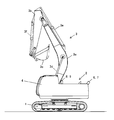
- FIG. 1 is an external view of a hydraulic excavator shown as an example of a construction machine according to a first embodiment of the present invention.
- the hydraulic excavator (construction machine) includes a crawler-type lower traveling body 1, an upper rotating body 2 provided so as to be able to turn with respect to the lower traveling body 1, and a front working machine for performing excavation work and the like. It has 3 and.
- a pair of left and right traveling hydraulic motors (not shown) are arranged on the lower traveling body 1, and each crawler is independently rotationally driven by the traveling hydraulic motor and its reduction mechanism, etc., and travels forward or backward.
- the upper swing body 2 is provided with an operating device for performing various operations of the hydraulic excavator, a driver's cab 4 in which a driver's seat or the like in which an operator is seated, a prime mover such as an engine, a hydraulic pump, a swing motor (not shown), and the like.
- the swivel motor swivels the upper swivel body 2 to the right or left with respect to the lower traveling body 1.
- a display device 5 shown in FIG. 2) for displaying various instruments and machine information is provided so that the operator can check the status of the hydraulic excavator (working machine).
- the front working machine 3 is composed of a boom 3a, an arm 3b, and a bucket 3c.
- the boom 3a is moved up and down by the boom cylinder 3d
- the arm 3b is moved up and down by the arm cylinder 3e on the dump side (opening side) or the cloud side (scratching).
- the bucket 3c is operated to the dump side or the cloud side by the bucket cylinder 3f.
- 3D sensors 6, 7, 8 and 9 as obstacle detection devices for detecting surrounding obstacles are mounted on the vehicle body at the rear end, the left end and the right end of the hydraulic excavator.
- the 3D sensor is an infrared sensor of the optical pulse flight time measurement method (TOF, Time-of-flight) method, which determines the detection / non-detection of an object within a predetermined detection range and detects an obstacle inside the sensor. It is possible to determine whether it is time or not, and output the determination result by CAN communication.
- TOF optical pulse flight time measurement method
- FIG. 2 is a diagram showing a mounting position and a detection area of the obstacle detection device (3D sensors 6 to 9).
- a 3D sensor 6 is mounted on the left side of the rear end of the vehicle body, a 3D sensor 7 is mounted on the right side of the rear end, a 3D sensor 8 is mounted on the left end, and a 3D sensor 9 is mounted on the right end.
- the 3D sensor is set to a width (angle) that can be detected in the vertical direction and the horizontal direction, and it is possible to cover the space behind the vehicle body within the detection range of these four 3D sensors.
- a detection area is set to reduce the possibility of an accident due to contact between the construction machine that starts moving the hydraulic excavator and surrounding workers. That is, the detection area is set so that obstacles existing in the range in which the upper swing body 2 moves can be detected in a short time when the hydraulic excavator starts turning and running, and the range detected by the 3D sensor 6 is detected in the detection area. 10.
- the range detected by the 3D sensor 7 is defined as the detection area 11
- the range detected by the 3D sensor 8 is defined as the detection area 12
- the range detected by the 3D sensor 9 is defined as the detection area 13.
- Each of the detection areas 10 to 13 is set at a position higher than that of the lower traveling body 1 so as not to detect the crawler of the lower traveling body 1 as an obstacle. (Explanation of the state considered as obstacle detection)
- Each of the 3D sensors 6 to 9 determines whether or not an obstacle exists in each of the detection areas 10 to 13.
- FIG. 3 is a diagram showing a system configuration in this embodiment.
- a vehicle body controller 14 that controls the operation of the entire body, and a lock switch 15 that is a lever-type switch for switching an operation lock device that switches all the operations of the vehicle body.
- a display device 5 that displays various instruments and aircraft information so that the operator can check the status of the hydraulic excavator, and a switch box 16 for manually changing the engine speed and operating the display device 5.
- a monitor controller 17 that receives various switch inputs of the switch box 16 and changes the display contents of the display device 5 is provided.
- an operating device for performing various operations of the hydraulic excavator is provided.
- a turning operation lever 19 representing one of a left turning operation and a right turning operation, a right forward running operation, a right reverse running operation, a left forward running operation, and a left reverse running are shown.
- 3 of the traveling operation lever 20 representing one of the operations and the front operation lever 21 representing one of the boom raising operation, boom lowering operation, arm cloud operation, arm dump operation, bucket cloud operation, and bucket dump operation. It is displayed on behalf of the two operating levers.
- the hydraulic excavator of this embodiment is equipped with an engine 22 as a prime mover, and the engine control device 23 electrically connected to the engine 22 is the engine 22 from the temperature sensor and the pickup signal incorporated in the engine 22.
- the number of revolutions and torque are controlled by grasping the state and controlling valves and the like.
- the vehicle body controller 14, the monitor controller 17, and the engine controller 23 are connected by CAN communication, and each of them transmits and receives necessary information.
- the vehicle body controller 14 determines the engine target speed according to the engine control dial voltage, the operating state of the operating levers 19 to 21, the pump load state, and the temperature condition, and determines the engine target speed. It is transmitted to the engine control device 23.
- the engine control device 23 controls the engine 22 so as to reach the engine target rotation speed, calculates the engine actual rotation speed from the signal of the pickup sensor built in the engine 22, and transmits the engine actual rotation speed to the vehicle body controller 14.
- Send Since the monitor controller 17 can acquire the engine target rotation speed and the engine actual rotation speed on the CAN communication, the engine target rotation speed and the engine actual rotation speed are displayed on the display device 5 as one of the vehicle body status displays. It is also possible to display.
- the hydraulic oil discharged from the variable displacement hydraulic pump 24 driven by the engine 22 passes through the control valve 25 that controls the flow of oil to the actuator, and passes through the traveling motor 3h, the swivel motor 3g, the boom cylinder 3d, and the arm cylinder 3e. , Is supplied to the bucket cylinder 3f.
- a hydraulic excavator is equipped with multiple hydraulic pumps in consideration of the situation where multiple actuators are operated at the same time, but in FIG. 3, one of them is shown as a representative.
- the operating levers 19 to 21 are composed of a pilot valve which is a manual pressure reducing valve, and the primary pressure is reduced according to the lever operating amount to generate a pilot valve secondary pressure.
- the generated secondary pressure moves a plurality of spools (direction switching valves) in the control valve 25, thereby adjusting the flow of hydraulic oil discharged from the pump 24, thereby enabling the corresponding actuator to be operated.
- the hydraulic source 26 from the pilot pump driven by the engine 22 is supplied to the pump regulator 27 and the lock valve 28 which is an operation lock device, and the pilot primary pressure (4 MPa) is maintained by the pilot relief valve (not shown). There is.
- the pump regulator 27 includes a pump flow rate control solenoid valve which is an electromagnetic proportional valve for reducing the pilot primary pressure from the hydraulic source 26 and using it, and the current (mA) output by the vehicle body controller 14. The pilot primary pressure is reduced accordingly.
- the pump regulator 27 has a built-in tilt (pressing volume) control mechanism for the pump 24, and the volume (or discharge) of the pump 24 is adjusted according to the pump flow rate control pressure which is the output (secondary pressure) of the pump flow rate control electromagnetic valve. Flow rate) is controlled.
- the pump regulator 27 has a characteristic that the pump volume is the minimum when the pump flow rate control pressure is the minimum (0 MPa) and the pump volume is the maximum when the pump flow rate control pressure is the maximum (4 MPa).
- the pump flow rate control solenoid valve is in the cutoff position (0 MPa) in the uncontrolled state (0 mA), and has a characteristic that the pump flow rate control pressure increases as the vehicle body controller 14 increases the command current. ..
- the pump regulator 27 is provided with a pump flow rate control pressure sensor 33 for detecting the pump flow rate control pressure.
- the signal of the pump flow rate control pressure sensor 33 is input to the vehicle body controller 14, and the vehicle body controller 14 estimates the pump volume from the characteristics of the pump volume with respect to the pump flow rate control pressure and multiplies the engine rotation speed to discharge the hydraulic pump 24. The flow rate is calculated.
- the lock valve 28 is an operation lock device that switches whether or not all the vehicle bodies can be operated.
- the lock valve 28 is switched between a cutoff position and a communication position by a solenoid driven by the vehicle body controller 14.
- the lock switch 15 When the lock lever (not shown) installed in the driver's cab 4 is in the locked position, the lock switch 15 is in the OFF state (open between terminals). The vehicle body controller 14 monitors the state of the lock switch 15, and when the lock switch 15 is OFF, the lock valve 28 is set to the non-excited state (blocking position).
- the lock switch 15 When the lock lever installed in the driver's cab 4 is in the unlocked position, the lock switch 15 is in the ON state (conduction between terminals). The vehicle body controller 14 monitors the state of the lock switch 15, and when the lock switch 15 is ON, 24V is applied to the lock valve 28 to bring it into an excited state (communication position).
- the pilot primary pressure is supplied to the turning operation lever 19, the traveling operation lever 20, and the front operation lever 21. Therefore, the secondary pressure of the pilot valve increases according to the operation of the operating levers 19 to 21, and the spool in the control valve 25 can be switched, so that the vehicle body can operate.
- the pilot circuit between the swivel operation lever 19 and the control valve 25 is provided with a swivel operation pressure sensor 29 for detecting the secondary pressure of the pilot valve.
- the pilot circuit between the travel operation lever 20 and the control valve 25 is provided with a travel operation pressure sensor 30 for detecting the secondary pressure of the pilot valve.
- the pilot circuit between the front operating lever 21 and the control valve 25 is provided with a front operating pressure sensor 31 for detecting the secondary pressure of the pilot valve.
- the signals of the turning operation pressure sensor 29, the traveling operation pressure sensor 30, and the front operation pressure sensor 31 are input to the vehicle body controller 14, and the vehicle body controller 14 grasps the operation status of the hydraulic excavator.
- the vehicle body controller 14 determines whether or not the vehicle body is operated based on the inputs from the operating pressure sensors 29 to 31.
- the delivery circuit between the hydraulic pump 24 and the control valve 25 is provided with a pump discharge pressure sensor 32 for detecting the pump discharge pressure.
- the signal of the pump discharge pressure sensor 32 is input to the vehicle body controller 14, and the vehicle body controller 14 grasps the pump load of the hydraulic excavator.
- the vehicle body controller 14 calculates the pump target flow rate by operation according to the input of the engine speed and the operating pressure sensors 29 to 31. Further, the vehicle body controller 14 calculates the limited horsepower (kW) according to the engine speed, the operating condition, and other vehicle body conditions (temperature, etc.), and from the input of the pump discharge pressure sensor 32 and the limited horsepower, the pump is limited by horsepower. Calculate the upper limit flow rate. The vehicle body controller 14 selects the smaller of the pump target flow rate by operation and the pump upper limit flow rate due to horsepower limitation as the pump target flow rate, and drives the pump flow rate control solenoid valve so as to reach that flow rate.
- a surrounding detection monitor 18 for notifying the operator of the detection information of the 3D sensors 6 to 9 and the state of vehicle body operation restriction by the surrounding detection is provided.
- the 3D sensors 6 to 9, the surrounding detection monitor 18, and the vehicle body controller 14 are connected by CAN communication, and each of them transmits and receives necessary information.
- the vehicle body controller 14 and the surrounding detection monitor 18 can know whether or not obstacles are detected in each of the detection areas 10 to 13, and the vehicle body controller 14 is an obstacle detection device.
- an obstacle person / object
- the vehicle body controller 14 is an obstacle detection device.
- the pilot circuit between the turning operation lever 19 and the control valve 25 is provided with a turning pilot pressure shutoff solenoid valve 34 as one of the vehicle body operation limiting devices.
- the turning pilot pressure shutoff solenoid valve 34 is in a circuit communication state when not controlled (0 mA), and becomes a circuit cutoff state when the current (mA) output by the vehicle body controller 14 increases, so that the turning operation becomes impossible.
- a traveling pilot pressure shutoff solenoid valve 35 is provided as one of the vehicle body operation limiting devices.
- the traveling pilot pressure shutoff solenoid valve 35 is in a circuit communication state when not controlled (0 mA), and becomes a circuit cutoff state when the current (mA) output by the vehicle body controller 14 increases, so that the traveling operation cannot be performed.
- the control release switch 36 which is a momentary type push button switch, is provided in the driver's cab 4 as a control release device.
- control release switch 36 When the control release switch 36 is not pressed, the control release switch 36 is in the OFF state (open between terminals), and when the control release switch 36 is pressed, the control release switch 36 is ON (between the terminals). It is in the (conducting) state.
- the vehicle body controller 14 monitors the ON / OFF state of the control release switch 36 and recognizes whether or not the control release switch 36 is pressed.
- the control release switch 36 may be provided as one of the grip switches of the operation levers 19 to 21, or may be provided as an individual switch located at a place different from the operation levers 19 to 21.
- FIG. 4 is a diagram showing the configuration of the controller 14 regarding the vehicle body operation restriction at the time of obstacle detection in this embodiment.
- the vehicle body controller 14 has an operation restriction control unit 37 as a control unit for restricting vehicle body operation when an obstacle is detected.
- the operation restriction control unit 37 includes a control state switching determination unit 38 as a control unit for determining whether the control mode state of the vehicle body is a normal state, a temporary release state, or a constant release state.
- the operation restriction control unit 37 includes an operation restriction command unit 39 as a control unit for instructing the operation of the operation restriction device.
- the vehicle body controller 14 includes a detection determination unit 40 for determining whether or not there is an obstacle around the vehicle body from the detection states of the detection areas 10 to 13, and each operation pressure sensor.
- Operation state determination unit for determining whether or not the vehicle body is in an operated / non-operated state from the magnitude of each operating pressure converted into a pressure value (MPa) in the vehicle body controller 14 according to the input voltage from 29 to 31.
- 41 and the solenoid valve drive unit 42 for calculating the current value for driving the turning pilot pressure shutoff solenoid valve 34 or the traveling pilot pressure shutoff solenoid valve 35 in response to the turning stop command or the running stop command of the operation limiting command unit 39.
- It has an engine rotation control unit 43 for limiting the engine target rotation speed instructed to the engine control device 23 in response to the rotation speed command of the operation restriction command unit 39.
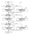
- FIG. 5 is a flowchart showing the processing contents of the detection determination unit 40.
- step S1 it is determined whether or not the 3D sensor 6 detects an object (person / object) in the detection area 10 (step S1). If it is detected in the detection area 10, it is determined that the vehicle body is in the detection state, and the obstacle detection state v1 which is a variable is set as "detection" (step S6).
- step S2 If it is not detected in the detection area 10, it is determined whether or not the 3D sensor 7 is detecting an object in the detection area 11 (step S2). If it is detected in the detection area 11, it is determined that the vehicle body is in the detection state, and the obstacle detection state v1 which is a variable is set as "detection" (step S6).
- step S3 it is determined whether or not the 3D sensor 8 is detecting an object in the detection area 12 (step S3). If it is detected in the detection area 12, it is determined that the vehicle body is in the detection state, and the obstacle detection state v1 which is a variable is set as "detection" (step S6).
- step S4 it is determined whether or not the 3D sensor 9 is detecting an object in the detection area 13 (step S4). If it is detected in the detection area 13, it is determined that the vehicle body is in the detection state, and the obstacle detection state v1 which is a variable is set as "detection" (step S6).
- FIG. 6 is a flowchart showing a portion of the processing content of the operation state determination unit 41 for determining the operation state for each operation.
- step S33 it is determined whether or not the turning operation pressure is equal to or higher than the operation ON threshold C1 (for example, 0.5 MPa) (step S33). If the operation ON threshold value is C1 or higher, it is determined that the turning operation state is being operated, and the turning operation state v10, which is a variable, is set to “operating” (step S34). If it is less than the operation ON threshold value C1, it is determined that the turning is not operated, and the turning operation state v10, which is a variable, is set to “non-operation” (step S35).
- the operation ON threshold value for example, 0.5 MPa
- step S36 it is determined whether or not the traveling operation pressure is equal to or higher than the operation ON threshold value C1 (for example, 0.5 MPa) (step S36). If the operation ON threshold value is C1 or higher, it is determined that the traveling operation is being performed, and the traveling operation state v11, which is a variable, is set to “operating” (step S37). If it is less than the operation ON threshold value C1, it is determined that the running is not operated, and the running operation state v11, which is a variable, is set to “non-operation” (step S38).
- the operation ON threshold value C1 for example, 0.5 MPa
- step S39 it is determined whether or not the front operating pressure is equal to or higher than the operation ON threshold C1 (for example, 0.5 MPa) (step S39). If the operation ON threshold value is C1 or higher, it is determined that the front is being operated, and the variable front operation state v12 is set to "operating" (step S40). If it is less than the operation ON threshold value C1, it is determined that the front is not operated, and the front operation state v12, which is a variable, is set to “non-operation” (step S41).
- the operation ON threshold value for example, 0.5 MPa
- FIG. 7 is a flowchart showing a portion of the processing content of the operation state determination unit 41 for determining the operation state of the vehicle body.
- step S7 it is determined whether or not the turning operation state v10 is "in operation” (step S7). If it is "in operation”, it is determined that the vehicle body is in the operating state, and the variable vehicle body operating state v2 is set to "in operation” (step S11).
- step S8 it is determined whether or not the running operation state v11 is "in operation” (step S8). If it is "in operation”, it is determined that the vehicle body is in the operating state, and the variable vehicle body operating state v2 is set to "in operation” (step S11).
- step S9 it is determined whether or not the front operation state v12 is "in operation” (step S9). If it is "in operation”, it is determined that the vehicle body is in an operating state, and the vehicle body operating state v2, which is a variable, is set as "in operation” (step S11).
- FIG. 8 is a flowchart showing the entire processing content of the control state switching determination unit 38.
- step S12 Select the processing content to be performed depending on whether the current control mode state v3 (one step before in control) is "normal”, “temporary release”, or “always release” (step S12).
- step S13 When the current control mode state v3 is "normal”, the switching determination from the normal mode (step S13) is executed.
- step S14 When the current control mode state v3 is "temporary release”, the switching determination (step S14) from the temporary release mode is executed.
- step S15 When the current control mode state v3 is "always released”, the switching determination (step S15) from the always released mode is executed.
- the initial value of the control mode state v3 is set to "normal", and after the key is turned off once, the control mode state v3 is always set to "normal” when the next engine is started, and the process is started.
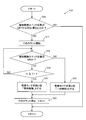
- FIG. 9 is a flowchart showing the processing content of the switching determination (step S13) from the normal mode, which is a subroutine of the control state switching determination unit 38.
- the vehicle body controller 14 determines the state of whether or not the control release switch 36 is pressed by the opening / continuity of the terminal of the control release switch 36. In this embodiment, the time when the control release switch 36 is pressed is treated as the control release switch state “ON”, and the time when the control release switch 36 is not pressed is treated as the control release switch state “OFF”.
- step S13 In the switching determination from the normal mode (step S13), first, whether or not the control release switch state has changed from OFF to ON (the control release switch 36 has changed from a non-pressed state to a pressed state). Whether or not) is determined (step S16).
- step S16 If NO is determined in step S16, the control release switch 36 is not pressed, so the process ends without switching the control mode state v3 from "normal".
- step S17 When the control release switch 36 is pressed and the control release switch state changes from OFF to ON, counting of the control release switch ON time t1 is started (step S17).
- step S18 it is determined whether or not the control release switch state is ON (whether or not the control release switch 36 is pressed) (step S18).
- the control release switch is ON, it is determined whether or not the control release switch ON time t1 is equal to or longer than the release mode determination time T1 (for example, 2 seconds) (step S19). If the control release switch ON time t1 is less than the release mode determination time T1, the process returns to step S18 and the process is repeated.
- step S18 When it is determined in step S18 that the control release switch state is not ON, that is, when the control release switch 36 is not pressed before the control release switch ON time t1 reaches the release mode determination time T1. Switches the control mode state v3 to "temporary release" (step S20).
- control release switch ON time t1 becomes the release mode determination time T1 or more while the control release switch state is ON, that is, the control release switch 36 is pressed until the control release switch ON time t1 reaches the release mode determination time T1. If the button is held down for a long time, the control mode state v3 is switched to "always released" (step S21).
- step S22 After switching the control mode state v3 from "normal” in step S20 or step S21, the count of the control release switch ON time t1 is stopped and reset to the initial value (0) (step S22).
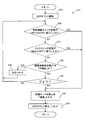
- FIG. 10 is a flowchart showing the processing content of the switching determination (step S14) from the temporary release mode, which is a subroutine of the control state switching determination unit 38.
- the vehicle body controller 14 determines the state of whether or not the lock switch 15 is pressed by opening / conducting the terminal of the lock switch 15.
- the time when the lock lever installed in the driver's cab 4 is in the locked position and the lock switch 15 is not pressed is treated as the lock switch state "OFF".
- the vehicle body controller 14 sets the lock valve 28 to a non-excited shutoff position, and disables all operations of the vehicle body.
- the time when the lock lever installed in the driver's cab 4 is in the unlocked position and the lock switch 15 is pressed is treated as the lock switch state "ON".
- the vehicle body controller 14 applies 24 V to the lock valve 28 to bring it into an excited state (communication position), enabling the vehicle body to operate.
- step S23 the count of the non-detection time t2 is started (step S23).
- control release switch state has changed from OFF to ON (whether or not the switch has changed from a non-pressed state to a pressed state) (step S24).
- step S24 If YES is determined in step S24, the control mode state v3 is switched to "normal" (step S25). After that, the count of the non-detection time t2 is stopped, the value is reset to the initial value (0) (step S26), and the process ends.
- step S27 If the control release switch 36 is not pressed and the control release switch state remains OFF, then whether the lock switch state has changed from ON to OFF (whether the lock lever has changed from the lock release position to the lock position). ) Is determined (step S27).
- step S27 If YES is determined in step S27, the control mode state v3 is switched to "normal" (step S25). After that, the count of the non-detection time t2 is stopped, the non-detection time t2 is reset to the initial value (0) (step S26), and the process ends.
- step S28 it is determined whether or not the obstacle detection state v1 is "non-detection" (step S28).
- the obstacle detection state v1 is not “non-detection”
- the control mode state v3 is "temporarily released”.
- the non-detection time t2 is reset to the initial value (0) (step S29), and the process returns to step S24 to continue the determination process.
- step S28 when the obstacle detection state v1 is "non-detection", it is determined whether or not the non-detection time t2 is equal to or longer than the control mode return time T2 (for example, 30 seconds) (step S30). If the non-detection time t2 is less than the control mode return time T2, the process returns to step S24 and the process is repeated.
- the control mode return time T2 for example, 30 seconds
- step S25 When the non-detection time t2 becomes the control mode return time T2 or more while the obstacle is not detected, the control mode state v3 is switched to "normal" (step S25). After that, the count of the non-detection time t2 is stopped and reset to the initial value (0) (step S26), and the process ends.
- FIG. 11 is a flowchart showing the processing content of the switching determination (step S15) from the constant release mode, which is a subroutine of the control state switching determination unit 38.
- step S15 it is determined whether or not the control release switch state has changed from OFF to ON (whether or not the control release switch 36 has changed from a state in which it has not been pressed to a state in which it has been pressed) (step S31).
- FIG. 12 is a flowchart showing the processing contents of the operation restriction command unit 39.
- step S42 it is determined whether or not the control mode state v3 is "normal” (step S42).
- the control mode state v3 is "normal” (when it is not “temporarily released” or “always released"), it is subsequently determined whether or not the obstacle detection state v1 is "detected” (step S43).
- the operation restriction command unit 39 sets the rotation speed command v6 to "limit rotation speed” (for example, 800 rpm) (step S44). ..
- the engine speed of the vehicle body is limited to a low level through the processing of the engine rotation control unit 43, which will be described later.
- a high engine speed for example, 1800 rpm
- the engine speed drops when an obstacle is detected, so that the operator can notice the detection as a sensation in addition to the alarm and display. Therefore, the safety can be further improved.
- step S45 it is determined whether or not the turning operation state v10 is "non-operation" (step S45).
- the turning stop command v4 is set to the “blocking pressure” (for example, 0 MPa) (step S46).
- the turning operation is disabled through the processing of the solenoid valve drive unit 42, which will be described later.
- step S47 it is determined whether or not the traveling operation state v11 is "non-operation" (step S47).
- the traveling stop command v5 is set to the “blocking pressure” (for example, 0 MPa) (step S48).
- the vehicle body movement restriction that restricts the vehicle body movement is activated.
- step S43 when the object (person / object) around the vehicle body is no longer detected and the obstacle detection state v1 is no longer "detection" (when it becomes “non-detection"), whether or not the lock switch state is OFF is determined.
- the rotation speed command v6 is set to the "maximum rotation speed” (for example, 2000 rpm) (step S50), and the rotation stop command is set.
- Set v4 to "open pressure” (for example, 4 MPa) step S51
- step S52 set the running stop command v5 to "open pressure” (for example, 4 MPa)
- FIG. 13 is a flowchart showing the processing contents of the solenoid valve driving unit 42.
- the solenoid valve drive unit 42 and the solenoid valve pressure shutoff solenoid valve 34 which is a vehicle body operation limiting device, actually respond to the solenoid valve pressures of the turning stop command v4 and the traveling stop command v5, which are the calculation results of the operation limiting command unit 39.
- This is a control unit that drives the traveling pilot pressure shutoff solenoid valve 35.
- step S53 it is determined whether or not the turning stop command v4 is "blocking pressure” (step S53).
- the turning pilot pressure breaking solenoid valve current v7 is set to “breaking current” (for example, 600 mA) (step S54).
- the turning pilot pressure breaking solenoid valve current v7 is set to the “opening current” (for example, 0 mA) (step S55).
- step S56 it is determined whether or not the running stop command v5 is the "blocking pressure" (step S56).
- the traveling pilot pressure breaking solenoid valve current v8 is set to “breaking current” (for example, 600 mA) (step S57).
- the traveling pilot pressure breaking solenoid valve current v8 is set to the “opening current” (for example, 0 mA) (step S58).
- the vehicle body controller 14 has a built-in solenoid valve driver, which is an analog output circuit for driving the solenoid of the proportional solenoid valve, so that the turning pilot pressure breaking solenoid valve current v7 and the traveling pilot pressure breaking solenoid valve current v8 are obtained.
- a current is passed through the circuit to drive the turning pilot pressure shutoff solenoid valve 34 and the traveling pilot pressure shutoff solenoid valve 35 (step S59).
- FIG. 14 is a flowchart showing the processing contents of the engine rotation control unit 43.
- the required rotation speed according to the engine control dial voltage operated by the operator the required rotation speed according to the operation amount of the operation lever, the required rotation according to the operating environment such as the radiator water temperature and the hydraulic oil temperature.
- the actual engine speed required for the vehicle body is realized by selecting the number or the like under predetermined conditions and finally transmitting the engine target speed v9 to the engine control device 23 through CAN communication.
- the required rotation speed by the processing common to the conventional hydraulic excavator other than the rotation speed command v6 sent from the operation restriction command unit 39 is determined in advance by the processing of the portion not shown in FIG. It is calculated as the reference required rotation speed v13 (step S60).
- the comparison between the rotation speed command v6 and the reference required rotation speed v13 is performed in the final stage of the processing of the engine rotation control unit 43.
- step S60 the engine rotation control unit 43 determines whether the rotation speed command v6 sent from the operation restriction command unit 39 is larger than the reference required rotation speed v13 (step). S61).
- the rotation speed command v6 is a "maximum rotation speed” (for example, 2000 rpm) larger than the reference required rotation speed v13.
- the engine target rotation speed v9 is set to ".
- “reference required rotation speed v13” it can be used as a normal hydraulic excavator (step S62).
- the rotation speed command v6 is a "limit rotation speed” (for example, 800 rpm) of the reference required rotation speed v13 or less. In that case, the engine target rotation speed v9 is “rotated”.
- the engine speed is forcibly limited and the operation of the vehicle body is limited (step S63).
- a controller 14 that performs operation restriction control that limits the operation of the actuators 3d to 3h when the obstacle detection device (3D sensors 6 to 9) detects an obstacle, and an instruction for canceling the operation restriction control.
- the controller 14 is a control mode in which the operation restriction control is enabled and a control mode in which the operation restriction control is temporarily released. It has a temporary release mode, and in the normal mode, it shifts to the temporary release mode due to the operation of the control release device (control release switch 36), and in the temporary release mode, the operation of the control release device (control release switch 36). When a predetermined condition not caused by the above is satisfied, the normal mode is restored.
- the operator operates the control release switch 36 to limit the operation from the normal mode in which the operation restriction is activated. Since it shifts to the temporary release mode that does not operate, it is possible to perform the work as a normal hydraulic excavator even if there are objects necessary for the work around the vehicle body. Further, in the temporary release mode, when a predetermined condition not caused by the operation of the control release switch 36 is satisfied, the normal mode is restored regardless of the operation of the control release switch 36, so that an accident due to contact between the construction machine and surrounding workers It is possible to reduce the possibility of occurrence.
- the hydraulic excavator according to the present embodiment can be switched between a lock position (blocking position) for prohibiting the operation of the actuators 3d to 3h and an unlocking position (communication position) for permitting the operation of the actuators 3d to 3h.
- the lock device (lock valve 28) is further provided, and the predetermined condition includes that the operation lock device (lock valve 28) is switched from the unlock position (communication position) to the lock position (blocking position).
- the temporary release mode is restored to the normal mode. Therefore, when the next vehicle body starts to move, it is restarted.
- the vehicle body movement restriction device that detects obstacles is activated to improve safety.
- the temporary release mode is returned to the normal mode by operating the lock valve 28 (operation lock device), which was also performed in the conventional construction machine, the normal mode is restored even if the operator forgets to return from the temporary release mode. It is possible to return, and it is possible to obtain the effect of improving safety, which reduces the possibility of an accident occurring due to contact between the construction machine that has started moving and surrounding workers.
- the predetermined condition includes that the state in which the obstacle detection device (3D sensors 6 to 9) does not detect an obstacle continues for a predetermined time (control mode return time T2).
- the temporary release mode is started when the control mode return time T2 (for example, 30 seconds) elapses in the state where the obstacle detection state v1 is "non-detection". Since it returns to the normal mode, it is possible to return to the normal mode even if the operator forgets to return from the temporary release mode, and an accident may occur due to contact between the construction machine that has started moving and surrounding workers. The effect of improving safety can be obtained.
- T2 for example, 30 seconds
- the control mode return time T2 is set in advance in consideration of workability and safety. In order to improve safety, it is better to return from the temporary release state to the normal state in the shortest possible time, but this may reduce workability.
- control mode return time T2 is set longer than necessary (for example, 10 minutes) by giving too much priority to not automatically returning during work, the control is released even after there are no objects around. In this case as well, the originally intended effect of improving safety cannot be obtained because the operation time is long.
- control mode return time T2 needs to be set in advance in consideration of workability and safety.
- the controller 14 further has a constant release mode which is a control mode in which the operation restriction control is constantly released, and in the normal mode, depending on the operation method of the control release device (control release switch 36), the controller 14 has a control mode. It is determined whether to shift to the temporary release mode or the constant release mode, and in the constant release mode, the normal mode is restored due to the operation of the control release device (control release switch 36).
- the control release device (control release switch 36) is composed of a momentary type push button switch, and the controller 14 is in the normal mode, the pressing duration of the control release switch 36 (control release switch ON time t1).
- the mode shifts to the temporary release mode, and in the normal mode, the pressing duration of the control release switch 36 (control release switch ON time t1) is the predetermined time (release mode determination).
- the time is T1 or more, the mode always shifts to the release mode.
- the possibility of an accident due to the contact between the construction machine and the surrounding workers is reduced while ensuring the workability in the situation where the objects necessary for the work exist around the vehicle body. It is possible to provide a construction machine that can achieve both safety and workability.
- a second embodiment of the present invention will be described with reference to FIG. In this embodiment, it is possible to shift from the normal mode to the temporary release mode without operating the control release switch 36.
- the differences from the first embodiment will be mainly described.
- FIG. 15 is a flowchart showing an additional processing portion of the switching determination (step S13) from the normal mode, which is a subroutine of the control state switching determination unit 38 in this embodiment. That is, the control state switching determination unit 38 in this embodiment executes the process of FIG. 15 in parallel with the process of FIG. 9 as the switching determination (step S13) from the normal mode.
- step S64 the counting of the operation time t3 during detection is started.
- step S65 it is determined whether or not the obstacle detection state v1 is "detection” (step S65), and if it is not “detection” (in the case of “non-detection"), the counting of the operation time t3 during detection is stopped and initially. The value (0) is reset (step S69), and the process ends.
- step S66 it is determined whether or not the vehicle body operation state v2 is "in operation” (step S66), and when it is not “in operation” (when it is “non-operation"), it is determined. , The counting of the operation time t3 during detection is stopped and reset to the initial value (0) (step S69), and the process is terminated.
- step S67 it is determined whether or not the detection operation time t3 is equal to or longer than the temporary release automatic transition time T3 (for example, 5 seconds) (step S67).
- step S68 When the detected operation time t3 reaches the temporary release automatic transition time T3, the control mode state v3 is set to "temporary release" (step S68), the counting of the detected operation time t3 is stopped, and the detected operation time t3 is set to the initial value. The process is reset to (0) (step S69), and the process ends.
- step S65 If the operation time t3 during detection is less than the temporary release automatic transition time T3, the process returns to step S65, and the determination for the obstacle detection state v1 and the determination for the vehicle body operation state v2 are repeated.
- the additional processing portion of the switching determination from the normal mode shown in FIG. 15 is that the operator continues to operate the vehicle body while working in the normal mode, in a state where an obstacle is detected and the vehicle body operation restriction is activated. This makes it possible to automatically shift to the temporary release mode without pressing the control release switch 36.
- the hydraulic excavator according to the present embodiment further includes an operation detection device (operation pressure sensors 29 to 31) for detecting the presence or absence of operation of the operation device (operation levers 19 to 21), and the controller 14 releases control in the normal mode.
- the operation detection device (operation pressure sensors 29 to 31) is the operation device (operation pressure sensor 29 to 31) while the obstacle detection device (3D sensors 6 to 9) detects an obstacle.
- the operation of the operation levers 19 to 21) is continuously detected for a predetermined time (temporary release automatic transition time T3) or longer, the mode shifts to the temporary release mode.
- the vehicle body operation limit When an obstacle is detected, the vehicle body operation limit is activated, the engine speed is limited, and the vehicle body operation is slowed down, and the turning pilot pressure shutoff solenoid valve 34 and the traveling pilot pressure shutoff solenoid valve 35 are switched to the shutoff position. It becomes impossible to turn / run. However, even if an obstacle is detected, it is necessary to cancel the operation of the vehicle body movement restriction in order to move away from the obstacle or to continue the work in the presence of surrounding obstacles after confirming the safety of the surroundings.
- control release switch 36 when the vehicle body operation restriction is released by the control release switch 36, and the control release switch 36 is installed in a place different from the operation levers 19 to 21, the operator once moves from the operation levers 19 to 21. It is necessary to press the control release switch 36 after releasing.
- the vehicle body can be continuously moved and safely stopped rather than the operation levers 19 to 21 being released to press the control release switch 36 and the vehicle body being stopped once. There may be times when it is better to keep the car moving.
- the mode shifts to the temporary release mode and the vehicle body operation restriction is released, so that the vehicle body is not stopped. It is possible to move to a place where it can be stopped safely and change the posture.
- the present invention is not limited to the above-mentioned examples, and includes various modifications.
- the above-described embodiment has been described in detail in order to explain the present invention in an easy-to-understand manner, and is not necessarily limited to those having all the described configurations. It is also possible to add a part of the configuration of another embodiment to the configuration of one embodiment, delete a part of the configuration of one embodiment, or replace it with a part of another embodiment. It is possible.
- Travel operation pressure sensor (operation detection device), 31 ... Front operation pressure sensor (operation detection device), 32 ... Pump discharge pressure sensor, 33 ... Pump flow control pressure sensor, 34 ... Swivel pilot pressure cutoff Electromagnetic valve, 35 ... Traveling pilot pressure cutoff electromagnetic valve, 36 ... Control release switch (control release device), 37 ... Operation restriction control unit, 38 ... Control state switching determination unit, 39 ... Operation restriction command unit, 40 ... Detection determination unit , 41 ... Operation state determination unit, 42 ... Electromagnetic valve drive unit, 43 ... Engine rotation control unit.
Landscapes
- Engineering & Computer Science (AREA)
- Mining & Mineral Resources (AREA)
- Civil Engineering (AREA)
- General Engineering & Computer Science (AREA)
- Structural Engineering (AREA)
- Mechanical Engineering (AREA)
- Radar, Positioning & Navigation (AREA)
- Remote Sensing (AREA)
- Physics & Mathematics (AREA)
- Fluid Mechanics (AREA)
- Component Parts Of Construction Machinery (AREA)
- Operation Control Of Excavators (AREA)
Abstract
車体周囲に作業に必要な物体が存在する状況での作業性を確保しつつ、建設機械と周囲作業者の接触による事故発生の可能性を下げる、安全性と作業性を両立させた建設機械を提供する。 コントローラは、動作制限制御を有効とした制御モードである通常モードと、前記動作制限制御を一時的に解除した制御モードである一時解除モードとを有し、前記通常モードにおいて、前記制御解除装置の操作に起因して前記一時解除モードに移行し、前記一時解除モードにおいて、前記制御解除装置の操作に起因しない所定の条件が成立した場合に、前記通常モードに復帰する。
Description
本発明は、車体と周囲の障害物(人・物)との接触の可能性を下げるために、車体周囲の障害物を検知し、障害物の検知状況に応じて車体の動作を制限する機能を備えた建設機械に関するものである。
建設機械による事故の形態として、建設機械と周囲作業者の接触によるものが想定されており、事故発生を回避するための手段として、周囲の障害物(人・物)をセンサにより検出してオペレータに通知を行うものや、検出時に車体の動作速度を制限したり自動で停止させたりする建設機械およびその制御装置が多く提案されている。
しかし、現実の稼働現場の状況として、建設機械の周囲になんらかの物体(例えば、ダンプへの積込用の土砂山や土留めのための壁、他の建設機械やダンプ等)が存在する環境での稼働や、オペレータと周囲作業者の同意の元での周囲作業者を置いた作業等、車体の周囲に障害物(人・物)が存在するやむをえない状況での稼働が発生する。
また、上記のような場面に限らずとも、建設機械が障害物を検知して動作制限が作動した場合において障害物を排除することが難しい場合、検知状態のままその場から建設機械を移動させることが必要な状況が発生する。
このような状況を想定し、周囲障害物を検知したときに車体の動作を制限する機能を備えた建設機械において、オペレータが動作制限を解除することができる手段を搭載し、オペレータが解除手段を操作することで、障害物検知状態のまま通常の油圧ショベルと同様に車体を動かすことを可能としているものがある。
特許文献1には、動作制限の解除方法に関する発明として、人検知時の動作制限作動時に、キャビン(運転室)内での所定操作で動作制限を解除し、解除する際の検知非検知状況に応じて動作制限からの復帰の緩やかさを変える建設機械が示されている。
特許文献1は、オペレータが特定の解除操作によって障害物検知時の動作制限を解除することを許可しており、その解除時に急な速度変化とならないようにすることでより安全に解除する方法を提案している。
しかし、特許文献1を含む従来技術において、動作制限を解除する機能についての言及はあるものの、基本的には解除が必要な状況をイレギュラーなものとして扱っており、動作制限を解除した状態で使い続ける状況を許可するような使い方は検討がなされていない。
また、特許文献1においては、動作制限を解除する方法については言及されているが、動作制限が解除された状態から通常状態(人検知で車体動作が制限される状態)への復帰方法については明確に言及されていない。
周囲障害物の検知機能が、真に検知が必要な障害物(例えば、不意に作業範囲内に進入してくる人)のみを検出できる性能があれば、動作制限を解除する状況は通常の作業時にはほぼ発生せず、動作制限の解除が必要な状況はイレギュラーなものと言うことも可能だが、検知機能の能力が発展途上な現在の建設機械においては、車体の周囲になにかしらの物体が存在する状況で作業することは十分想定されるため、安全性と作業性の両立のためには、動作制限を解除した状態で建設機械を稼働させる状況を積極的に許可するような使い方を前提として運転者支援機能を構築する必要がある。
車体の周囲になにかしらの物体が存在する状況で作業することが想定される建設機械においては、通常の作業中に作業に必要な物体(例えば、ダンプ積込のための土砂山)を障害物として検知してしまうことが考えられるが、それによって車体動作に制限がかかってしまっていては、建設機械は本来の用途である作業機械としての性能を発揮することができず、作業性能の著しい低下という問題を発生させてしまう。
作業性を低下させないように、従来技術で公開されているように、オペレータが動作制限を解除すると、建設機械は従来通り周囲に障害物があっても動作に制限がかかることなく作業を行うことが可能となるが、当然建設機械と周囲作業者の接触による事故の発生を回避するための機能が作動しないので、本来意図している安全性の向上がなされなくなるという問題を発生させてしまう。
さらに、オペレータが動作制限を解除して必要な作業を行った後に、周囲の稼働環境の状況に応じてその都度動作制限を有効に戻してくれればよいが、オペレータが戻し操作をし忘れた場合に、オペレータが動作制限が作動するものと思い込んでしまい周囲確認を怠ってしまうという新たな問題が発生する懸念がある。
本発明は、上記の課題を解決するために考案したもので、車体周囲に作業に必要な物体が存在する状況での作業性を確保しつつ、建設機械と周囲作業者の接触による事故発生の可能性を下げることができる、安全性と作業性を両立させた建設機械を提供することを目的とする。
上記目的を達成するために、本発明は、アクチュエータと、周囲の障害物を検出する障害物検出装置と、前記障害物検出装置が障害物を検出した場合に前記アクチュエータの動作を制限する動作制限制御を行うコントローラと、前記動作制限制御の解除を指示するための制御解除装置とを備えた建設機械において、前記コントローラは、前記動作制限制御を有効とした制御モードである通常モードと、前記動作制限制御を一時的に解除した制御モードである一時解除モードとを有し、前記通常モードにおいて、前記制御解除装置の操作に起因して前記一時解除モードに移行し、前記一時解除モードにおいて、前記制御解除装置の操作に起因しない所定の条件が成立した場合に、前記通常モードに復帰するものとする。
以上のように構成した本発明によれば、制御解除装置の操作によって動作制限が作動する通常モードから動作制限が作動しない一時解除モードに移行するため、車体周囲に作業に必要な物体が存在する状況での作業性を確保することが可能となる。また、一時解除モードにおいて制御解除装置の操作に起因しない所定の条件が成立することにより、制御解除装置の操作によらず通常モードに復帰するため、建設機械と周囲作業者の接触による事故発生の可能性を下げることが可能となる。
本発明に係る建設機械によれば、車体周囲に作業に必要な物体が存在する状況での作業性を確保しつつ、建設機械と周囲作業者の接触による事故発生の可能性を下げることにより、安全性と作業性を両立させることができる。
以下、本発明の実施の形態を図面を参照して説明する。なお、各図中、同等の部材には同一の符号を付し、重複した説明は適宜省略する。
(油圧ショベルの説明)
図1は、本発明の第1の実施例に係る建設機械の一例として示す油圧ショベルの外観図である。
図1は、本発明の第1の実施例に係る建設機械の一例として示す油圧ショベルの外観図である。
図1において、油圧ショベル(建設機械)は、クローラ式の下部走行体1と、下部走行体1に対して旋回可能に設けられた上部旋回体2と、掘削作業などを行うためのフロント作業機3とを備えている。
下部走行体1には左右一対の走行用油圧モータ(図示せず)が配置され、この走行用油圧モータ及びその減速機構等により各クローラが独立して回転駆動され、前方又は後方に走行する。
上部旋回体2には、油圧ショベルの各種操作を行う操作装置やオペレータが着席する運転席等が配置された運転室4、エンジン等の原動機、油圧ポンプ及び旋回モータ(図示せず)などが備えられており、この旋回モータにより上部旋回体2が下部走行体1に対して右方向又は左方向に旋回される。運転室4の内部には、オペレータが油圧ショベル(作業機械)の状況を確認できるように各種の計器類や機体情報が表示される表示装置5(図2に示す)が設けられている。
フロント作業機3は、ブーム3a、アーム3b及びバケット3cから構成されており、ブーム3aはブームシリンダ3dにより上下動され、アーム3bはアームシリンダ3eによりダンプ側(開く側)又はクラウド側(掻き込む側)に操作され、バケット3cはバケットシリンダ3fによりダンプ側又はクラウド側に操作される。
(障害物検出装置に関する説明)
油圧ショベルの後端、左端および右端の車体上には、周囲障害物を検出するための障害物検出装置としての3Dセンサ6,7,8,9が搭載されている。3Dセンサは、光パルス飛行時間計測法(TOF、Time-of-flight)方式の赤外線センサであり、予め定められた検知範囲内の物体の検知/未検知を判定し、センサ内部で障害物検出時か否かの判定を行い、その判定結果をCAN通信によって出力することができる。
(障害物検出装置および検知領域に関する説明)
図2は、障害物検出装置(3Dセンサ6~9)の搭載位置および検知領域を示す図である。
(障害物検出装置に関する説明)
油圧ショベルの後端、左端および右端の車体上には、周囲障害物を検出するための障害物検出装置としての3Dセンサ6,7,8,9が搭載されている。3Dセンサは、光パルス飛行時間計測法(TOF、Time-of-flight)方式の赤外線センサであり、予め定められた検知範囲内の物体の検知/未検知を判定し、センサ内部で障害物検出時か否かの判定を行い、その判定結果をCAN通信によって出力することができる。
(障害物検出装置および検知領域に関する説明)
図2は、障害物検出装置(3Dセンサ6~9)の搭載位置および検知領域を示す図である。
車体後端左側に3Dセンサ6、後端右側に3Dセンサ7、左端に3Dセンサ8、右端に3Dセンサ9を搭載している。3Dセンサには垂直方向および水平方向に検知可能な広さ(角度)が設定されており、この4つの3Dセンサの検知範囲で車体周囲後方の空間をカバーすることが可能となっている。
それぞれの3Dセンサの検知範囲を利用し、油圧ショベル動き出しの建設機械と周囲作業者の接触による事故発生の可能性を下げるための検知領域が設定されている。すなわち、油圧ショベルの旋回・走行の動き出しの短時間に上部旋回体2が移動する範囲に存在する障害物を検出できるように検知領域を設定しており、3Dセンサ6が検出する範囲を検知領域10、3Dセンサ7が検出する範囲を検知領域11、3Dセンサ8が検出する範囲を検知領域12、3Dセンサ9が検出する範囲を検知領域13と定めている。
各検知領域10~13は、下部走行体1のクローラを障害物として検出してしまわないように、下部走行体1よりも高い位置に設定されている。
(障害物検出とみなす状態に関する説明)
各3Dセンサ6~9は、それぞれの検知領域10~13に障害物が存在するか否かを判定している。
(障害物検出とみなす状態に関する説明)
各3Dセンサ6~9は、それぞれの検知領域10~13に障害物が存在するか否かを判定している。
また、障害物検出装置である3Dセンサ6~9によって作成される検知領域10~13の領域内に1つ以上の障害物(人・物)があるとセンサによって判定された時を本実施例では障害物検出時とみなす。
(システム構成の説明 通常の油圧ショベルとしての構成部分)
図3は、本実施例におけるシステム構成を示す図である。
(システム構成の説明 通常の油圧ショベルとしての構成部分)
図3は、本実施例におけるシステム構成を示す図である。
本実施例の油圧ショベルの運転室4内には、機体全体の動作を制御する車体コントローラ14と、車体の全ての動作可否を切り替える動作ロック装置を切り替えるためのレバー式スイッチであるロックスイッチ15と、オペレータが油圧ショベルの状況を確認できるように各種の計器類や機体情報が表示される表示装置5と、エンジン回転数を手動で変更したり表示装置5を操作したりするためのスイッチボックス16と、スイッチボックス16の各種スイッチ入力を受け付け、表示装置5の表示内容を変更するモニタコントローラ17が設けられている。
また、油圧ショベルの運転室4内には、油圧ショベルの各種操作を行う操作装置が設けられている。図3では、操作装置を示すものとして、左旋回操作、右旋回操作のうちの一つを表す旋回操作レバー19と、右前進走行操作、右後進走行操作、左前進走行操作、左後進走行操作のうちの一つを表す走行操作レバー20と、ブーム上げ操作、ブーム下げ操作、アームクラウド操作、アームダンプ操作、バケットクラウド操作、バケットダンプ操作のうちの一つを表すフロント操作レバー21の3つの操作レバーを代表して表示している。
本実施例の油圧ショベルは原動機としてエンジン22を搭載しており、エンジン22と電気的に接続されているエンジン制御装置23は、エンジン22に組み込まれている温度センサやピックアップの信号からエンジン22の状態を把握し、バルブ等を制御することで回転数やトルクを制御している。
車体コントローラ14、モニタコントローラ17、エンジン制御装置23はCAN通信によって接続されており、それぞれ必要な情報の送受信を行っている。
例えば、エンジン回転数制御については、車体コントローラ14が、エンジンコントロールダイヤル電圧や操作レバー19~21の操作状態、ポンプ負荷状態や温度条件に応じてエンジン目標回転数を決め、そのエンジン目標回転数をエンジン制御装置23に送信する。エンジン制御装置23は、エンジン目標回転数となるようにエンジン22を制御し、エンジン22に内蔵されているピックアップセンサの信号からエンジン実回転数を演算し、そのエンジン実回転数を車体コントローラ14に送信する。モニタコントローラ17においては、CAN通信上にあるエンジン目標回転数とエンジン実回転数を取得することが可能なので、表示装置5に、車体の状態表示の一つとしてエンジン目標回転数やエンジン実回転数を表示することも可能である。
エンジン22によって駆動される可変容量式油圧ポンプ24から吐出される作動油は、アクチュエータへの油の流れを制御するコントロールバルブ25を通り、走行モータ3h、旋回モータ3g、ブームシリンダ3d、アームシリンダ3e、バケットシリンダ3fに供給される。
なお、通常油圧ショベルには複数のアクチュエータを同時操作する状況などを考慮し、複数台の油圧ポンプが搭載されているが、図3では、そのうちの一つを代表して表示している。
操作レバー19~21は手動の減圧弁であるパイロットバルブで構成され、レバー操作量に応じて一次圧を減圧し、パイロットバルブ二次圧を生成する。生成された二次圧はコントロールバルブ25内に複数あるスプール(方向切換弁)を動かし、それによってポンプ24から吐出される作動油の流れを調整することで、対応するアクチュエータを操作可能とする。
エンジン22によって駆動されるパイロットポンプからの油圧源26は、ポンプレギュレータ27および、動作ロック装置であるロックバルブ28に供給されており、図示しないパイロットリリーフバルブによってパイロット一次圧(4MPa)が保たれている。
ポンプレギュレータ27の中には、油圧源26からのパイロット一次圧を減圧して使用するための電磁比例弁であるポンプ流量制御電磁弁が含まれており、車体コントローラ14が出力する電流(mA)に応じてパイロット一次圧を減圧する。ポンプレギュレータ27はポンプ24の傾転(押除け容積)制御機構を内蔵しており、ポンプ流量制御電磁弁の出力(二次圧)であるポンプ流量制御圧に応じてポンプ24の容積(または吐出流量)を制御する。
ポンプレギュレータ27は、ポンプ流量制御圧が最小(0MPa)ではポンプ容積最小で、ポンプ流量制御圧が最大(4MPa)ではポンプ容積最大となるような特性を持っている。
ポンプ流量制御電磁弁は、非制御状態(0mA)では遮断位置(0MPa)となっており、車体コントローラ14が指令電流を増加させることにしたがってポンプ流量制御圧が増加するような特性を持っている。
ポンプレギュレータ27には、ポンプ流量制御圧を検出するためのポンプ流量制御圧センサ33が設けられている。
ポンプ流量制御圧センサ33の信号は車体コントローラ14に入力され、車体コントローラ14はポンプ流量制御圧に対するポンプ容積の特性から、ポンプ容積を推定し、エンジン回転数を掛け合わせることで油圧ポンプ24の吐出流量を演算している。
ロックバルブ28は、車体の全ての動作可否を切り替える動作ロック装置である。ロックバルブ28は車体コントローラ14によって駆動するソレノイドによって遮断位置と連通位置とに切り換えられる。
運転室4内に設置されたロックレバー(図示せず)がロック位置にあるとき、ロックスイッチ15はOFF(端子間は開放)状態になっている。車体コントローラ14はロックスイッチ15の状態を監視し、ロックスイッチ15がOFFのときはロックバルブ28を非励磁状態(遮断位置)とする。
運転室4内に設置されたロックレバーがロック解除位置にあるとき、ロックスイッチ15はON(端子間は導通)状態になっている。車体コントローラ14はロックスイッチ15の状態を監視し、ロックスイッチ15がONのときにはロックバルブ28に24Vを印加し励磁状態(連通位置)とする。
ロックバルブ28が遮断位置のときには、旋回操作レバー19、走行操作レバー20、フロント操作レバー21へパイロット一次圧が供給されない。そのため、操作レバー19~21を操作してもパイロットバルブ二次圧が上昇せず、コントロールバルブ25内のスプールを切り替えられないため、車体の全ての動作が不可となる。
ロックバルブ28が連通位置のときには、旋回操作レバー19、走行操作レバー20、フロント操作レバー21へパイロット一次圧が供給される。そのため、操作レバー19~21の操作に応じてパイロットバルブ二次圧が増加し、コントロールバルブ25内のスプールを切り替えることができるようになることで車体が動作可能となる。
旋回操作レバー19とコントロールバルブ25の間のパイロット回路には、パイロットバルブ二次圧を検出するための旋回操作圧センサ29が設けられている。走行操作レバー20とコントロールバルブ25の間のパイロット回路には、パイロットバルブ二次圧を検出するための走行操作圧センサ30が設けられている。
フロント操作レバー21とコントロールバルブ25の間のパイロット回路には、パイロットバルブ二次圧を検出するためのフロント操作圧センサ31が設けられている。
フロント操作レバー21とコントロールバルブ25の間のパイロット回路には、パイロットバルブ二次圧を検出するためのフロント操作圧センサ31が設けられている。
旋回操作圧センサ29、走行操作圧センサ30、フロント操作圧センサ31の信号は車体コントローラ14に入力され、車体コントローラ14は油圧ショベルの操作状況を把握している。
車体コントローラ14は、操作圧センサ29~31からの入力に基づいて車体の操作有無を判定する。
油圧ポンプ24とコントロールバルブ25の間のデリベリ回路には、ポンプ吐出圧を検出するためのポンプ吐出圧センサ32が設けられている。
ポンプ吐出圧センサ32の信号は車体コントローラ14に入力され、車体コントローラ14は油圧ショベルのポンプ負荷を把握している。
車体コントローラ14は、エンジン回転数や操作圧センサ29~31の入力に応じて操作によるポンプ目標流量を算出する。また、車体コントローラ14は、エンジン回転数や操作状況やその他の車体状態(温度等)に応じて制限馬力(kW)を演算し、ポンプ吐出圧センサ32の入力と制限馬力から、馬力制限によるポンプ上限流量を算出する。車体コントローラ14は、操作によるポンプ目標流量と馬力制限によるポンプ上限流量の小さい方をポンプ目標流量として選択し、その流量になるようにポンプ流量制御電磁弁を駆動する。
(システム構成の説明 前提とする周囲検知動作制限システムとしての構成部分)
油圧ショベルの運転室4内には、3Dセンサ6~9の検知情報や周囲検知による車体動作制限の状態をオペレータに通知するための周囲検知モニタ18を備えている。
(システム構成の説明 前提とする周囲検知動作制限システムとしての構成部分)
油圧ショベルの運転室4内には、3Dセンサ6~9の検知情報や周囲検知による車体動作制限の状態をオペレータに通知するための周囲検知モニタ18を備えている。
3Dセンサ6~9と、周囲検知モニタ18と、車体コントローラ14はCAN通信によって接続されており、それぞれ必要な情報の送受信を行っている。
このCAN通信により、車体コントローラ14や周囲検知モニタ18は、検知領域10~13それぞれについて障害物を検知しているかを知ることが可能となっており、さらに、車体コントローラ14は、障害物検出装置である3Dセンサ6~9によって作成される検知領域10~13の1つ以上に障害物(人・物)が存在する場合に、障害物検知と判定し、検知領域10~13のいずれにも障害物(人・物)が存在しない場合に、障害物非検知と判定する。
旋回操作レバー19とコントロールバルブ25の間のパイロット回路には、車体動作制限装置の一つとして旋回パイロット圧遮断電磁弁34が設けられている。
旋回パイロット圧遮断電磁弁34は、非制御時(0mA)では回路連通状態であり、車体コントローラ14が出力する電流(mA)が大きくなることで回路遮断状態となり、旋回動作が不可となる。
また、走行操作レバー20とコントロールバルブ25の間のパイロット回路には、車体動作制限装置の一つとして走行パイロット圧遮断電磁弁35が設けられている。
走行パイロット圧遮断電磁弁35は、非制御時(0mA)では回路連通状態であり、車体コントローラ14が出力する電流(mA)が大きくなることで回路遮断状態となり、走行動作が不可となる。
(システム構成の説明 本発明での追加部分)
本実施例では、運転室4内に制御解除装置としてモーメンタリ型の押しボタンスイッチである制御解除スイッチ36を備えている。
(システム構成の説明 本発明での追加部分)
本実施例では、運転室4内に制御解除装置としてモーメンタリ型の押しボタンスイッチである制御解除スイッチ36を備えている。
制御解除スイッチ36が押されていない時、制御解除スイッチ36はOFF(端子間は開放)状態になっており、制御解除スイッチ36が押されている時、制御解除スイッチ36はON(端子間は導通)状態になっている。車体コントローラ14は制御解除スイッチ36のON/OFF状態を監視し、制御解除スイッチ36が押されているか否かを認識する。
制御解除スイッチ36は操作レバー19~21のグリップスイッチの一つとして設けてもよいし、操作レバー19~21とは別の場所にある個別スイッチとして設けてもよい。
個別スイッチとして設置した場合、制御解除スイッチ36を押すためには操作レバーから手を離す必要があり、車体動作中に制御解除スイッチ36を押す状況となった場合には、オペレータは作業を一時中断する必要があるが、制御解除スイッチ36を押す前にオペレータに周囲確認の実施を促すという点においては、個別スイッチの方が効果的である。
(制御部の構成の説明)
図4は、本実施例における、障害物検出時の車体動作制限に関するコントローラ14の構成を示す図である。
(制御部の構成の説明)
図4は、本実施例における、障害物検出時の車体動作制限に関するコントローラ14の構成を示す図である。
車体コントローラ14は、障害物検出時に車体動作を制限するための制御部として、動作制限制御部37を有している。
動作制限制御部37は、車体の制御モード状態が通常状態か一時解除状態か常時解除状態かを判定するための制御部として、制御状態切替判定部38を含んでいる。
また、動作制限制御部37は、動作制限装置の作動を指令する制御部として、動作制限指令部39を含んでいる。
車体コントローラ14は、動作制限制御部37の他に、各検知領域10~13の検知状態から車体の周囲に障害物があるか否かを判定するための検知判定部40と、各操作圧センサ29~31からの入力電圧に応じて車体コントローラ14内で圧力値(MPa)に変換された各操作圧の大きさから車体が操作/非操作状態か否かを判定するための操作状態判定部41と、動作制限指令部39の旋回停止指令または走行停止指令を受けて旋回パイロット圧遮断電磁弁34または走行パイロット圧遮断電磁弁35を駆動する電流値を演算するための電磁弁駆動部42と、動作制限指令部39の回転数指令を受けてエンジン制御装置23に指示するエンジン目標回転数を制限するためのエンジン回転制御部43とを有している。
これら制御部の処理は、エンジン始動および周囲検知システム始動後(稼働中)は車体コントローラ14の制御周期毎に常に実行されている。
(各制御部の詳細説明)
図5~図14にて、図4で示した各制御部の詳細を説明する。
(各制御部の詳細説明 検知判定部)
図5は、検知判定部40の処理内容を示すフローチャートである。
(各制御部の詳細説明)
図5~図14にて、図4で示した各制御部の詳細を説明する。
(各制御部の詳細説明 検知判定部)
図5は、検知判定部40の処理内容を示すフローチャートである。
まず初めに3Dセンサ6が検知領域10で物体(人・物)を検知しているか否かを判定する(ステップS1)。検知領域10で検知していれば、車体が検知状態にあると判定し、変数である障害物検知状態v1を「検知」とする(ステップS6)。
検知領域10で検知していなければ、3Dセンサ7が検知領域11で物体を検知しているか否かを判定する(ステップS2)。検知領域11で検知していれば、車体が検知状態にあると判定し、変数である障害物検知状態v1を「検知」とする(ステップS6)。
検知領域11で検知していなければ、3Dセンサ8が検知領域12で物体を検知しているか否かを判定する(ステップS3)。検知領域12で検知していれば、車体が検知状態にあると判定し、変数である障害物検知状態v1を「検知」とする(ステップS6)。
検知領域12で検知していなければ、3Dセンサ9が検知領域13で物体を検知しているか否かを判定する(ステップS4)。検知領域13で検知していれば、車体が検知状態にあると判定し、変数である障害物検知状態v1を「検知」とする(ステップS6)。
検知領域10~13のいずれでも物体を検知しなければ、車体が非検知状態にあると判定し、変数である障害物検知状態v1を「非検知」とする(ステップS5)。
(各制御部の詳細説明 操作状態判定部)
図6は、操作状態判定部41の処理内容のうち、各操作について操作状態を判定する部分を示すフローチャートである。
(各制御部の詳細説明 操作状態判定部)
図6は、操作状態判定部41の処理内容のうち、各操作について操作状態を判定する部分を示すフローチャートである。
まず初めに旋回操作圧が操作ON閾値C1(例えば0.5MPa)以上か否かを判定する(ステップS33)。操作ON閾値C1以上であれば、旋回が操作されている状態であると判定し、変数である旋回操作状態v10を「操作中」とする(ステップS34)。操作ON閾値C1未満であれば、旋回が操作されていない状態であると判定し、変数である旋回操作状態v10を「非操作」とする(ステップS35)。
続いて、走行操作圧が操作ON閾値C1(例えば0.5MPa)以上か否かを判定する(ステップS36)。操作ON閾値C1以上であれば、走行が操作されている状態であると判定し、変数である走行操作状態v11を「操作中」とする(ステップS37)。操作ON閾値C1未満であれば、走行が操作されていない状態であると判定し、変数である走行操作状態v11を「非操作」とする(ステップS38)。
続いて、フロント操作圧が操作ON閾値C1(例えば0.5MPa)以上か否かを判定する(ステップS39)。操作ON閾値C1以上であれば、フロントが操作されている状態であると判定し、変数であるフロント操作状態v12を「操作中」とする(ステップS40)。操作ON閾値C1未満であれば、フロントが操作されていない状態であると判定し、変数であるフロント操作状態v12を「非操作」とする(ステップS41)。
図7は、操作状態判定部41の処理内容のうち、車体の操作状態を判定する部分を示すフローチャートである。
まず初めに、旋回操作状態v10が「操作中」か否かを判定する(ステップS7)。「操作中」であれば、車体が操作状態にあると判定し、変数である車体操作状態v2を「操作中」とする(ステップS11)。
旋回操作状態v10が「操作中」でなければ(「非操作」であれば)、走行操作状態v11が「操作中」か否かを判定する(ステップS8)。「操作中」であれば、車体が操作状態にあると判定し、変数である車体操作状態v2を「操作中」とする(ステップS11)。
走行操作状態v11が「操作中」でなければ(「非操作」であれば)、フロント操作状態v12が「操作中」か否かを判定する(ステップS9)。「操作中」であれば、車体として操作状態であると判定し、変数である車体操作状態v2を「操作中」とする(ステップS11)。
旋回操作状態v10、走行操作状態v11、フロント操作状態v12の全てが「操作中」でなければ(「非操作」であれば)、車体が非操作状態にあると判定し、変数である車体操作状態v2を「非操作」とする(ステップS10)。
(各制御部の詳細説明 制御状態切替判定部)
図8は、制御状態切替判定部38の処理内容の全体を示すフローチャートである。
(各制御部の詳細説明 制御状態切替判定部)
図8は、制御状態切替判定部38の処理内容の全体を示すフローチャートである。
現在(制御上は1ステップ前)の制御モード状態v3が「通常」、「一時解除」、「常時解除」のどれであるかによって行う処理内容を選択する(ステップS12)。
現在の制御モード状態v3が「通常」であるとき、通常モードからの切替判定(ステップS13)を実行する。現在の制御モード状態v3が「一時解除」であるとき、一時解除モードからの切替判定(ステップS14)を実行する。現在の制御モード状態v3が「常時解除」であるとき、常時解除モードからの切替判定(ステップS15)を実行する。
なお、制御モード状態v3の初期値は「通常」とし、一度キーOFFしてから次のエンジン始動時には必ず制御モード状態v3を「通常」として処理を開始する。
図9は、制御状態切替判定部38のサブルーチンである通常モードからの切替判定(ステップS13)の処理内容を示すフローチャートである。
車体コントローラ14は、制御解除スイッチ36の端子の開放/導通によって制御解除スイッチ36が押されているか否かの状態を判定している。本実施例では、制御解除スイッチ36が押されているときを制御解除スイッチ状態「ON」、制御解除スイッチ36が押されていない時を制御解除スイッチ状態「OFF」として扱う。
通常モードからの切替判定(ステップS13)では、まず初めに、制御解除スイッチ状態がOFFからONに変化したか否か(制御解除スイッチ36が押されていない状態から押されている状態に変化したか否か)を判定する(ステップS16)。
ステップS16でNOと判定された場合、制御解除スイッチ36は押されていないので、制御モード状態v3を「通常」から切り替えることなく処理を終了する。
制御解除スイッチ36が押され、制御解除スイッチ状態がOFFからONに変化したら、制御解除スイッチON時間t1のカウントを開始する(ステップS17)。
次に、制御解除スイッチ状態がONか否か(制御解除スイッチ36が押されているか否か)を判定する(ステップS18)。制御解除スイッチがONの場合は、制御解除スイッチON時間t1が解除モード判別時間T1(例えば2秒)以上か否かを判定する(ステップS19)。制御解除スイッチON時間t1が解除モード判別時間T1未満の場合、ステップS18に戻り処理を繰り返す。
ステップS18において制御解除スイッチ状態がONでないと判定された場合、すなわち、制御解除スイッチON時間t1が解除モード判別時間T1に到達する前に制御解除スイッチ36が押されなくなるボタン短押しであった場合は、制御モード状態v3を「一時解除」に切り替える(ステップS20)。
制御解除スイッチ状態がONのまま制御解除スイッチON時間t1が解除モード判別時間T1以上となった場合、すなわち、制御解除スイッチON時間t1が解除モード判別時間T1に到達するまで制御解除スイッチ36を押し続けるボタン長押しであった場合には、制御モード状態v3を「常時解除」に切り替える(ステップS21)。
ステップS20またはステップS21によって制御モード状態v3を「通常」から切り替えたあとは、制御解除スイッチON時間t1のカウントを停止し、初期値(0)にリセットする(ステップS22)。
図10は、制御状態切替判定部38のサブルーチンである一時解除モードからの切替判定(ステップS14)の処理内容を示すフローチャートである。
車体コントローラ14は、ロックスイッチ15の端子の開放/導通によってロックスイッチ15が押されているか否かの状態を判定している。
本実施例では、運転室4内に設置されたロックレバーがロック位置にありロックスイッチ15が押されていないときをロックスイッチ状態「OFF」として扱う。車体コントローラ14は、ロックスイッチ状態がOFFのときにはロックバルブ28を非励磁状態の遮断位置とし、車体の全ての動作を不可としている。
また、本実施例では、運転室4内に設置されたロックレバーがロック解除位置にありロックスイッチ15が押されているときをロックスイッチ状態「ON」として扱う。車体コントローラ14は、ロックスイッチ状態がONのときにはロックバルブ28に24Vを印加し励磁状態(連通位置)とし、車体の動作を可能としている。
一時解除モードからの切替判定(ステップS14)では、まず初めに、非検知時間t2のカウントを開始する(ステップS23)。
続いて、制御解除スイッチ状態がOFFからONに変化したか否か(スイッチが押されていない状態から押されている状態に変化したか否か)を判定する(ステップS24)。
ステップS24でYESと判定された場合、制御モード状態v3を「通常」に切り替える(ステップS25)。その後、非検知時間t2のカウントを停止し、初期値(0)にリセットし(ステップS26)、処理を終了する。
制御解除スイッチ36が押されず制御解除スイッチ状態がOFFのままの場合、次に、ロックスイッチ状態がONからOFFに変化したか否か(ロックレバーがロック解除位置からロック位置に変化したか否か)を判定する(ステップS27)。
ステップS27でYESと判定された場合、制御モード状態v3を「通常」に切り替える(ステップS25)。その後、非検知時間t2のカウントを停止すると共に非検知時間t2を初期値(0)にリセットし(ステップS26)、処理を終了する。
ロックスイッチ15がロック位置にされずロックスイッチ状態がONのままの場合、次に、障害物検知状態v1が「非検知」か否かを判定する(ステップS28)。障害物検知状態v1が「非検知」でない場合、すなわち、3Dセンサ6~9が車体周囲の障害物を1つ以上検出している「検知」である場合は、制御モード状態v3を「一時解除」から切り替えず、非検知時間t2を初期値(0)にリセットし(ステップS29)、ステップS24に戻り判定処理を継続する。
ステップS28において、障害物検知状態v1が「非検知」である場合、非検知時間t2が制御モード復帰時間T2(例えば30秒)以上か否かを判定する(ステップS30)。非検知時間t2が制御モード復帰時間T2未満の場合、ステップS24に戻り処理を繰り返す。
障害物非検知のまま非検知時間t2が制御モード復帰時間T2以上となった場合には、制御モード状態v3を「通常」に切り替える(ステップS25)。その後、非検知時間t2のカウントを停止しかつ初期値(0)にリセットし(ステップS26)、処理を終了する。
図11は、制御状態切替判定部38のサブルーチンである常時解除モードからの切替判定(ステップS15)の処理内容を示すフローチャートである。
ステップS15では、制御解除スイッチ状態がOFFからONに変化したか否か(制御解除スイッチ36が押されていない状態から押されている状態に変化したか否か)を判定する(ステップS31)。
ステップS31でYESと判定された場合、制御モード状態v3を「通常」に切り替え(ステップS32)、処理を終了する。制御解除スイッチ36が押されず、制御解除スイッチ状態がOFFのままであれば、制御モード状態v3を「常時解除」から切り替えず、処理を終了する。
(各制御部の詳細説明 動作制限指令部)
図12は、動作制限指令部39の処理内容を示すフローチャートである。
(各制御部の詳細説明 動作制限指令部)
図12は、動作制限指令部39の処理内容を示すフローチャートである。
まず初めに、制御モード状態v3が「通常」か否かを判定する(ステップS42)。制御モード状態v3が「通常」であるとき(「一時解除」または「常時解除」でないとき)、続いて、障害物検知状態v1が「検知」か否かを判定する(ステップS43)。車体周囲に物体(人・物)があり障害物検知状態v1が「検知」であるとき、動作制限指令部39は回転数指令v6を「制限回転数」(例えば800rpm)とする(ステップS44)。
これにより、後述するエンジン回転制御部43の処理を通して、車体のエンジン回転数が低く制限される。通常作業時で、エンジン回転数高回転(例えば1800rpm)で稼働している場合、障害物検知時にエンジン回転数が下がることで、オペレータは警報や表示に加えて体感としても検知に気づくことができるため、より安全性を高めることができる。
また、障害物を検知している状態ではエンジン回転数が制限され、障害物検知を無視してそのまま同じ作業を続けることはできなくなるため、オペレータに対して、作業を一旦とめて周囲の安全確認を行うことを促すこともできる。
続いて、旋回操作状態v10が「非操作」か否かを判定する(ステップS45)。障害物を検知している状態において、旋回操作を行っていない「非操作」である場合、旋回停止指令v4を「遮断圧力」(例えば0MPa)とする(ステップS46)。
これにより、後述する電磁弁駆動部42の処理を通して、旋回操作が不能な状態とする。障害物が車体の周囲に存在する状態で旋回の始動停止を行うことで、油圧ショベルの動き出しにおける車体と周囲作業者の接触による事故の発生の可能性を下げることができる。
続いて、走行操作状態v11が「非操作」か否かを判定する(ステップS47)。障害物を検知している状態において、走行操作を行っていない「非操作」である場合、走行停止指令v5を「遮断圧力」(例えば0MPa)とする(ステップS48)。
これにより、後述する電磁弁駆動部42の処理を通して、走行操作が不能な状態とする。障害物が車体の周囲に存在する状態で走行の始動停止を行うことで、油圧ショベルの動き出しにおける車体と周囲作業者の接触による事故の発生の可能性を下げることができる。
以上のように、障害物検出時には、車体動作を制限する車体動作制限を作動させる。
次に、車体動作制限の解除に関する判定および制御処理について説明する。
ステップS43において、車体周囲に物体(人・物)を検出しなくなり障害物検知状態v1が「検知」ではなくなった場合(「非検知」となった場合)、ロックスイッチ状態がOFFか否かを判定する(ステップS49)。障害物を検知しなくなった状態において、ロックレバーがロック位置にありロックスイッチ状態がOFFである場合に、回転数指令v6を「最大回転数」(例えば2000rpm)とし(ステップS50)、旋回停止指令v4を「開放圧力」(例えば4MPa)とし(ステップS51)、走行停止指令v5を「開放圧力」(例えば4MPa)とする(ステップS52)。
ロックレバーがロック解除位置にありロックスイッチ状態がONである場合(OFFでない場合)には、障害物検知状態v1が「検知」でなくなったとしても車体動作制限は作動させたままとする。
ロックレバーがロック位置にある状態では、ロックバルブ28が遮断位置にあるため、車体の全ての動作が不可となっている。この状態でのみ車体動作制限を解除することを許可することで、例えば、オペレータが操作レバー19,20を意図せず倒していた状態において障害物非検知となったときに旋回/走行の動作制限が解除されて、車体が急に動き出してしまう状況が発生しないようにすることができ、より安全性を向上させることができる。
(各制御部の詳細説明 電磁弁駆動部)
図13は、電磁弁駆動部42の処理内容を示すフローチャートである。
(各制御部の詳細説明 電磁弁駆動部)
図13は、電磁弁駆動部42の処理内容を示すフローチャートである。
電磁弁駆動部42は、動作制限指令部39での演算結果である旋回停止指令v4と走行停止指令v5の電磁弁圧力に応じて実際に車体動作制限装置である旋回パイロット圧遮断電磁弁34と走行パイロット圧遮断電磁弁35を駆動する制御部である。
まず初めに、旋回停止指令v4が「遮断圧力」か否かを判定する(ステップS53)。「遮断圧力」の場合は、旋回パイロット圧遮断電磁弁電流v7を「遮断電流」(例えば600mA)とする(ステップS54)。「遮断圧力」でない場合(「開放圧力」の場合)は、旋回パイロット圧遮断電磁弁電流v7を「開放電流」(例えば0mA)とする(ステップS55)。
続いて、走行停止指令v5が「遮断圧力」か否かを判定する(ステップS56)。「遮断圧力」の場合は、走行パイロット圧遮断電磁弁電流v8を「遮断電流」(例えば600mA)とする(ステップS57)。「遮断圧力」でない場合(「開放圧力」の場合)は、走行パイロット圧遮断電磁弁電流v8を「開放電流」(例えば0mA)とする(ステップS58)。
車体コントローラ14には比例電磁弁のソレノイドを駆動するためのアナログ出力回路である電磁弁ドライバが内蔵されており、旋回パイロット圧遮断電磁弁電流v7と走行パイロット圧遮断電磁弁電流v8になるように回路に電流を流し、旋回パイロット圧遮断電磁弁34および走行パイロット圧遮断電磁弁35を駆動する(ステップS59)。
(各制御部の詳細説明 エンジン回転制御部)
図14は、エンジン回転制御部43の処理内容を示すフローチャートである。
(各制御部の詳細説明 エンジン回転制御部)
図14は、エンジン回転制御部43の処理内容を示すフローチャートである。
エンジン回転制御部43では、オペレータが操作するエンジンコントロールダイヤル電圧に応じた要求回転数や、操作レバーの操作量に応じた要求回転数、ラジエタ水温や作動油温等の稼働環境に応じた要求回転数などをあらかじめ定めた条件で選択し、最終的にエンジン目標回転数v9としてCAN通信を通してエンジン制御装置23に送信することで、車体として要求するエンジン実回転数を実現している。
本実施例では詳しく説明しないが、動作制限指令部39から送られる回転数指令v6以外の従来の油圧ショベルと共通の処理による要求回転数については、図14に記載していない部分の処理によってあらかじめ基準要求回転数v13として演算されている(ステップS60)。回転数指令v6と基準要求回転数v13との比較をエンジン回転制御部43の処理の最終段で行う。
エンジン回転制御部43では、基準要求回転数v13の演算処理(ステップS60)に続いて、動作制限指令部39から送られる回転数指令v6が基準要求回転数v13よりも大きいかを判定する(ステップS61)。
車体動作制限が作動していない時は、回転数指令v6は基準要求回転数v13よりも大きい「最大回転数」(例えば2000rpm)になっているため、その場合は、エンジン目標回転数v9を「基準要求回転数v13」とすることで、通常の油圧ショベルとして使用可能とする(ステップS62)。
車体動作制限が作動している時は、回転数指令v6は基準要求回転数v13以下の「制限回転数」(例えば800rpm)になっているため、その場合は、エンジン目標回転数v9を「回転数指令v6」とすることで、エンジン回転数を強制的に制限し、車体の動作を制限する(ステップS63)。
(第1の実施例の効果)
本実施例では、アクチュエータ3d~3hと、アクチュエータ3d~3hの動作を指示するための操作装置(操作レバー19~21)と、周囲の障害物を検出する障害物検出装置(3Dセンサ6~9)、障害物検出装置(3Dセンサ6~9)が障害物を検出した場合にアクチュエータ3d~3hの動作を制限する動作制限制御を行うコントローラ14と、前記動作制限制御の解除を指示するための制御解除装置(制御解除スイッチ36)とを備えた油圧ショベルにおいて、コントローラ14は、前記動作制限制御を有効とした制御モードである通常モードと、動作制限制御を一時的に解除した制御モードである一時解除モードとを有し、通常モードにおいて、制御解除装置(制御解除スイッチ36)の操作に起因して一時解除モードに移行し、一時解除モードにおいて、制御解除装置(制御解除スイッチ36)の操作に起因しない所定の条件が成立した場合に、通常モードに復帰する。
(第1の実施例の効果)
本実施例では、アクチュエータ3d~3hと、アクチュエータ3d~3hの動作を指示するための操作装置(操作レバー19~21)と、周囲の障害物を検出する障害物検出装置(3Dセンサ6~9)、障害物検出装置(3Dセンサ6~9)が障害物を検出した場合にアクチュエータ3d~3hの動作を制限する動作制限制御を行うコントローラ14と、前記動作制限制御の解除を指示するための制御解除装置(制御解除スイッチ36)とを備えた油圧ショベルにおいて、コントローラ14は、前記動作制限制御を有効とした制御モードである通常モードと、動作制限制御を一時的に解除した制御モードである一時解除モードとを有し、通常モードにおいて、制御解除装置(制御解除スイッチ36)の操作に起因して一時解除モードに移行し、一時解除モードにおいて、制御解除装置(制御解除スイッチ36)の操作に起因しない所定の条件が成立した場合に、通常モードに復帰する。
本実施例によれば、作業時の車体動かし始めにおいて、オペレータが周囲の安全確認を実施した後は、オペレータは制御解除スイッチ36を操作することで、動作制限が作動する通常モードから動作制限が作動しない一時解除モードに移行するため、車体周囲に作業に必要な物体が存在していても、通常の油圧ショベルとして作業を行うことが可能となる。また、一時解除モードにおいて制御解除スイッチ36の操作に起因しない所定の条件が成立することにより、制御解除スイッチ36の操作によらず通常モードに復帰するため、建設機械と周囲作業者の接触による事故発生の可能性を下げることが可能となる。
また、本実施例に係る油圧ショベルは、アクチュエータ3d~3hの動作を禁止するロック位置(遮断位置)とアクチュエータ3d~3hの動作を許可するロック解除位置(連通位置)とに切替操作可能な動作ロック装置(ロックバルブ28)を更に備え、前記所定の条件には、動作ロック装置(ロックバルブ28)がロック解除位置(連通位置)からロック位置(遮断位置)へ切り替わったことが含まれる。
これにより、作業を中断しロックレバーをロック状態にした段階(ロックスイッチ15がOFFになった段階)で一時解除モードから通常モードに復帰するため、その次の車体動かし始めの際には、再度障害物検知による車体動作制限装置が作動し、安全性を向上させる。また、従来の建設機械でも行っていたロックバルブ28(動作ロック装置)の操作により一時解除モードから通常モードに復帰するため、オペレータが一時解除モードからの戻し操作をし忘れていても通常モードに復帰することができ、動き出しの建設機械と周囲作業者の接触による事故発生の可能性を下げる安全性向上の効果を得ることができる。
また、本実施例において、前記所定の条件には、障害物検出装置(3Dセンサ6~9)が障害物を検出しない状態が所定時間(制御モード復帰時間T2)継続したことが含まれる。
これにより、ロックバルブ28(動作ロック装置)を操作していなくても、障害物検知状態v1が「非検知」の状態で制御モード復帰時間T2(例えば30秒)経過した時点で一時解除モードから通常モードに復帰するため、これによっても、オペレータが一時解除モードからの戻し操作をし忘れていても通常モードに復帰することができ、動き出しの建設機械と周囲作業者の接触による事故発生の可能性を下げる安全性向上の効果を得ることができる。
なお、制御モード復帰時間T2は、作業性と安全性をあらかじめ十分考慮して設定される。安全性を向上させるためにはできるだけ短時間で一時解除状態から通常状態に復帰させた方がよいが、それによって作業性を低下させる可能性がある。
例えば、油圧ショベルが、掘削、90°旋回、放土、戻り、という動作を繰り返すダンプ積込作業を実施中において、放土時のみ周囲障害物として作業対象の土砂山を検知する場合を考える。このとき、障害物の検知状況としては「検知」と「非検知」が油圧ショベルの動作に連動して交互に発生することとなる。制御モード復帰時間T2を、戻り、掘削、90°旋回、の合計時間よりも短く設定した場合、オペレータが車体動作制限を一時解除して作業していたとしても、1サイクルの間で、「非検知」の状態で“制御モード復帰時間T2が経過する”という状況が発生し一時解除モードから通常モードに復帰してしまう。この場合、オペレータは1サイクルごとに制御解除スイッチ36を押す必要があり、作業性を著しく低下してしまう。オペレータは作業性を確保するために、通常モードに自動で復帰しない常時解除モードで使用することが予想され、そうなると本来意図している安全性の向上の効果が得られない。
また、例えば反対に、作業中に自動復帰しないことを優先しすぎて制御モード復帰時間T2を必要以上に長く(例えば10分)に設定した場合は、周囲に物体がなくなったあとも制御解除状態で稼働する時間が長くなるため、この場合も本来意図している安全性の向上の効果が得られない。
よって、制御モード復帰時間T2は、作業性と安全性をあらかじめ十分考慮して設定される必要がある。
また、本実施例において、コントローラ14は、動作制限制御を常時解除した制御モードである常時解除モードを更に有し、通常モードにおいて、制御解除装置(制御解除スイッチ36)の操作方法に応じて、一時解除モードに移行するか常時解除モードに移行するかを決定し、常時解除モードにおいて、制御解除装置(制御解除スイッチ36)の操作に起因して通常モードに復帰する。本実施例では、制御解除装置(制御解除スイッチ36)は、モーメンタリ型の押しボタンスイッチで構成され、コントローラ14は、通常モードにおいて、制御解除スイッチ36の押下継続時間(制御解除スイッチON時間t1)が所定時間(解除モード判別時間T1)未満である場合に、一時解除モードに移行し、通常モードにおいて、制御解除スイッチ36の押下継続時間(制御解除スイッチON時間t1)が所定時間(解除モード判別時間T1)以上である場合に、常時解除モードに移行する。
これにより、単一の制御解除スイッチ36の操作を介して、一時解除モードに移行するか常時解除モードに移行するかを選択することが可能となる。
以上のように構成した本実施例によれば、車体周囲に作業に必要な物体が存在する状況での作業性を確保しつつ、建設機械と周囲作業者の接触による事故発生の可能性を下げることができる、安全性と作業性を両立させた建設機械を提供することができる。
本発明の第2の実施例について図15を用いて説明する。本実施例は、制御解除スイッチ36の操作によらず通常モードから一時解除モードへの移行を可能としたものである。以下、第1の実施例との相違点を中心に説明する。
図15は、本実施例における制御状態切替判定部38のサブルーチンである通常モードからの切替判定(ステップS13)の追加処理部分を示したフローチャートである。すなわち、本実施例における制御状態切替判定部38は、通常モードからの切替判定(ステップS13)として、図9の処理と並行して図15の処理を実行する。
まず、検知中操作時間t3のカウントを開始する(ステップS64)。
続いて、障害物検知状態v1が「検知」か否かを判定し(ステップS65)、「検知」でない場合(「非検知」の場合)は、検知中操作時間t3のカウントを停止しかつ初期値(0)にリセットし(ステップS69)、処理を終了する。
障害物検知状態v1が「検知」である場合は、車体操作状態v2が「操作中」か否かを判定し(ステップS66)、「操作中」でない場合(「非操作」である場合)は、検知中操作時間t3のカウントを停止しかつ初期値(0)にリセットし(ステップS69)、処理を終了する。
車体操作状態v2が「操作中」である場合は、検知中操作時間t3が一時解除自動移行時間T3(例えば5秒)以上となったか否かを判定する(ステップS67)。
検知中操作時間t3が一時解除自動移行時間T3に到達したら、制御モード状態v3を「一時解除」とし(ステップS68)、検知中操作時間t3のカウントを停止すると共に検知中操作時間t3を初期値(0)にリセットし(ステップS69)、処理を終了する。
検知中操作時間t3が一時解除自動移行時間T3未満の場合は、ステップS65に戻り、障害物検知状態v1についての判定および車体操作状態v2についての判定を繰り返す。
図15に示した通常モードからの切替え判定の追加処理部分は、通常モードで作業中に、障害物を検知して車体動作制限が作動している状態において、オペレータが車体の操作を継続することにより、制御解除スイッチ36を押さなくても自動で一時解除モードに移行することを可能としている。
(第2の実施例の効果)
本実施例に係る油圧ショベルは、操作装置(操作レバー19~21)の操作の有無を検出する操作検出装置(操作圧センサ29~31)を更に備え、コントローラ14は、通常モードにおいて、制御解除装置(制御解除スイッチ36)の操作に起因する場合の他、障害物検出装置(3Dセンサ6~9)が障害物を検出した状態で操作検出装置(操作圧センサ29~31)が操作装置(操作レバー19~21)の操作を所定時間(一時解除自動移行時間T3)以上継続して検出した場合に、一時解除モードに移行する。
(第2の実施例の効果)
本実施例に係る油圧ショベルは、操作装置(操作レバー19~21)の操作の有無を検出する操作検出装置(操作圧センサ29~31)を更に備え、コントローラ14は、通常モードにおいて、制御解除装置(制御解除スイッチ36)の操作に起因する場合の他、障害物検出装置(3Dセンサ6~9)が障害物を検出した状態で操作検出装置(操作圧センサ29~31)が操作装置(操作レバー19~21)の操作を所定時間(一時解除自動移行時間T3)以上継続して検出した場合に、一時解除モードに移行する。
障害物を検出すると、車体動作制限が作動し、エンジン回転数が制限されることで車体の動作が遅くなり、旋回パイロット圧遮断電磁弁34と走行パイロット圧遮断電磁弁35が遮断位置に切り替わることで旋回/走行が不能となる。しかし、障害物を検出したとしても、障害物から離れたり、周囲の安全確認後に周囲障害物がある状態で作業を継続したりするためには、車体動作制限の作動を解除する必要がある。
本発明の第1の実施例では、そのための方法として制御解除スイッチ36による車体動作制限の解除を可能としている。
ただし、制御解除スイッチ36による車体動作制限の解除を行う場合で、制御解除スイッチ36が操作レバー19~21とは別の場所に設置されている場合は、オペレータは操作レバー19~21から一度手を離してから制御解除スイッチ36を押す必要がある。
障害物検知時にオペレータに周囲の安全確認の実施を促すという点では、制御解除スイッチ36を押すために操作レバー19~21から手を離す必要があることは効果的である。
しかし、特に傾斜地やぬかるみや凹凸がある地面の路肩付近での稼働など、車体をすぐに停止させずある程度(障害物から離れる方に)移動してから停止させた方が、転倒や転落、滑りによる新たなリスクの発生を抑えられるといった状況も予見される。
この場合、特定の限られた状況によっては、制御解除スイッチ36を押すために操作レバー19~21から手を離して車体を一度停止させるよりも車体を動かし続けて確実に安全に停止できる状況まで車体を動かし続けた方がよいといったことがあるかもしれない。
本実施例によれば、障害物検知状態においても、一定時間操作レバー19~21を操作し続けた段階で一時解除モードに移行し車体動作制限が解除されるので、車体を停止させることなく、安全に停止できる場所への移動や姿勢の変更を実施することが可能となる。
もちろん、原則としては障害物検知時には、可能な限り速やかに安全に車体を停止し、周囲の安全確認を行った後に制御解除スイッチ36を押して一時解除モードに移行することが望ましいため、本実施例で追加している機能は、あくまで緊急的な機能として運用するように使用者への注意喚起が別途必要である。
以上、本発明の実施例について詳述したが、本発明は、上記した実施例に限定されるものではなく、様々な変形例が含まれる。例えば、上記した実施例は、本発明を分かり易く説明するために詳細に説明したものであり、必ずしも説明した全ての構成を備えるものに限定されるものではない。また、ある実施例の構成に他の実施例の構成の一部を加えることも可能であり、ある実施例の構成の一部を削除し、あるいは、他の実施例の一部と置き換えることも可能である。
1…下部走行体、2…上部旋回体、3…フロント作業機、3a…ブーム、3b…アーム、3c…バケット、3d…ブームシリンダ(アクチュエータ)、3e…アームシリンダ(アクチュエータ)、3f…バケットシリンダ(アクチュエータ)、3g…旋回モータ(アクチュエータ)、3h…走行モータ(アクチュエータ)、4…運転室、5…表示装置、6…3Dセンサ(障害物検出装置)、7…3Dセンサ(障害物検出装置)、8…3Dセンサ(障害物検出装置)、9…3Dセンサ(障害物検出装置)、10…検知領域、11…検知領域、12…検知領域、13…検知領域、14…車体コントローラ(コントローラ)、15…ロックスイッチ、16…スイッチボックス、17…モニタコントローラ、18…周囲検知モニタ、19…旋回操作レバー(操作装置)、20…走行操作レバー(操作装置)、21…フロント操作レバー(操作装置)、22…エンジン、23…エンジン制御装置、24…油圧ポンプ、25…コントロールバルブ、26…油圧源、27…ポンプレギュレータ、28…ロックバルブ(動作ロック装置)、29…旋回操作圧センサ(操作検出装置)、30…走行操作圧センサ(操作検出装置)、31…フロント操作圧センサ(操作検出装置)、32…ポンプ吐出圧センサ、33…ポンプ流量制御圧センサ、34…旋回パイロット圧遮断電磁弁、35…走行パイロット圧遮断電磁弁、36…制御解除スイッチ(制御解除装置)、37…動作制限制御部、38…制御状態切替判定部、39…動作制限指令部、40…検知判定部、41…操作状態判定部、42…電磁弁駆動部、43…エンジン回転制御部。
Claims (6)
- アクチュエータと、
前記アクチュエータの動作を指示するための操作装置と、
周囲の障害物を検出する障害物検出装置と、
前記障害物検出装置が障害物を検出した場合に前記アクチュエータの動作を制限する動作制限制御を行うコントローラと、
前記動作制限制御の解除を指示するための制御解除装置とを備えた建設機械において、
前記コントローラは、
前記動作制限制御を有効とした制御モードである通常モードと、前記動作制限制御を一時的に解除した制御モードである一時解除モードとを有し、
前記通常モードにおいて、前記制御解除装置の操作に起因して前記一時解除モードに移行し、
前記一時解除モードにおいて、前記制御解除装置の操作に起因しない所定の条件が成立した場合に、前記通常モードに復帰する
ことを特徴とする建設機械。 - 請求項1に記載の建設機械において、
前記アクチュエータの動作を禁止するロック位置と前記アクチュエータの動作を許可するロック解除位置とに切替操作可能な動作ロック装置を更に備え、
前記所定の条件には、前記動作ロック装置が前記ロック解除位置から前記ロック位置へ切り替わったことが含まれる
ことを特徴とする建設機械。 - 請求項1に記載の建設機械において、
前記所定の条件には、前記障害物検出装置が障害物を検出しない状態が所定時間継続したことが含まれる
ことを特徴とする建設機械。 - 請求項1に記載の建設機械において、
前記コントローラは、
前記動作制限制御を常時解除した制御モードである常時解除モードを更に有し、
前記通常モードにおいて、前記制御解除装置の操作方法に応じて、前記一時解除モードに移行するか前記常時解除モードに移行するかを決定し、
前記常時解除モードにおいて、前記制御解除装置の操作に起因して前記通常モードに復帰する
ことを特徴とする建設機械。 - 請求項4に記載の建設機械において、
前記制御解除装置は、モーメンタリ型の押しボタンスイッチで構成され、
前記コントローラは、
前記通常モードにおいて、前記押しボタンスイッチの押下継続時間が所定時間未満である場合に、前記一時解除モードに移行し、
前記通常モードにおいて、前記押しボタンスイッチの押下継続時間が前記所定時間以上である場合に、前記常時解除モードに移行する
ことを特徴とする建設機械。 - 請求項1に記載の建設機械において、
前記操作装置の操作の有無を検出する操作検出装置を更に備え、
前記コントローラは、前記通常モードにおいて、前記制御解除装置の操作に起因する場合の他、前記障害物検出装置が障害物を検出した状態で前記操作検出装置が前記操作装置の操作を所定時間以上継続して検出した場合に、前記一時解除モードに移行する
ことを特徴とする建設機械。
Priority Applications (5)
| Application Number | Priority Date | Filing Date | Title |
|---|---|---|---|
| CN202080053717.6A CN114207222B (zh) | 2019-09-25 | 2020-06-11 | 工程机械 |
| EP20867555.3A EP3985179A4 (en) | 2019-09-25 | 2020-06-11 | CONSTRUCTION MACHINE |
| KR1020227002341A KR102670015B1 (ko) | 2019-09-25 | 2020-06-11 | 건설 기계 |
| US17/623,637 US20220267998A1 (en) | 2019-09-25 | 2020-06-11 | Construction machine |
| US19/173,896 US20250237037A1 (en) | 2019-09-25 | 2025-04-09 | Construction machine |
Applications Claiming Priority (2)
| Application Number | Priority Date | Filing Date | Title |
|---|---|---|---|
| JP2019174667A JP7305274B2 (ja) | 2019-09-25 | 2019-09-25 | 建設機械 |
| JP2019-174667 | 2019-09-25 |
Related Child Applications (2)
| Application Number | Title | Priority Date | Filing Date |
|---|---|---|---|
| US17/623,637 A-371-Of-International US20220267998A1 (en) | 2019-09-25 | 2020-06-11 | Construction machine |
| US19/173,896 Continuation US20250237037A1 (en) | 2019-09-25 | 2025-04-09 | Construction machine |
Publications (1)
| Publication Number | Publication Date |
|---|---|
| WO2021059615A1 true WO2021059615A1 (ja) | 2021-04-01 |
Family
ID=75157271
Family Applications (1)
| Application Number | Title | Priority Date | Filing Date |
|---|---|---|---|
| PCT/JP2020/023097 Ceased WO2021059615A1 (ja) | 2019-09-25 | 2020-06-11 | 建設機械 |
Country Status (6)
| Country | Link |
|---|---|
| US (2) | US20220267998A1 (ja) |
| EP (1) | EP3985179A4 (ja) |
| JP (1) | JP7305274B2 (ja) |
| KR (1) | KR102670015B1 (ja) |
| CN (1) | CN114207222B (ja) |
| WO (1) | WO2021059615A1 (ja) |
Cited By (2)
| Publication number | Priority date | Publication date | Assignee | Title |
|---|---|---|---|---|
| EP4155468A1 (en) * | 2021-09-27 | 2023-03-29 | Yanmar Holdings Co., Ltd. | Work machine control system, work machine, method of controlling work machine, and work machine control program |
| WO2024111434A1 (ja) * | 2022-11-24 | 2024-05-30 | 住友建機株式会社 | ショベルの制御装置 |
Families Citing this family (7)
| Publication number | Priority date | Publication date | Assignee | Title |
|---|---|---|---|---|
| KR20220042059A (ko) * | 2019-08-08 | 2022-04-04 | 스미토모 겐키 가부시키가이샤 | 쇼벨 |
| JP7472991B2 (ja) * | 2020-08-28 | 2024-04-23 | 日本電気株式会社 | 建設機械の作業制御方法、作業制御システム及び作業制御装置 |
| JP7750718B2 (ja) * | 2021-11-18 | 2025-10-07 | ヤンマーホールディングス株式会社 | 建設機械 |
| JP2024004570A (ja) * | 2022-06-29 | 2024-01-17 | ヤンマーホールディングス株式会社 | 作業機械の制御方法、作業機械用制御プログラム、作業機械用制御システム及び作業機械 |
| JP2024069887A (ja) * | 2022-11-10 | 2024-05-22 | ヤンマーホールディングス株式会社 | 作業機械の制御方法、作業機械用制御プログラム、作業機械用制御システム及び作業機械 |
| JP2024141723A (ja) * | 2023-03-29 | 2024-10-10 | コベルコ建機株式会社 | 旋回式作業機械の制御装置 |
| JP2026032354A (ja) * | 2024-08-13 | 2026-02-26 | 株式会社小松製作所 | 作業機械の周辺監視システム、作業機械、及び作業機械の周辺監視方法 |
Citations (6)
| Publication number | Priority date | Publication date | Assignee | Title |
|---|---|---|---|---|
| JPH08302748A (ja) * | 1995-05-09 | 1996-11-19 | Hitachi Constr Mach Co Ltd | 作業機械の安全装置および駆動回路 |
| JP2009114750A (ja) * | 2007-11-07 | 2009-05-28 | Kobelco Contstruction Machinery Ltd | 作業機械の干渉防止装置 |
| US20140118533A1 (en) * | 2012-01-27 | 2014-05-01 | Doosan Infracore Co., Ltd. | Operational stability enhancing device for construction machinery |
| JP2015229837A (ja) * | 2014-06-03 | 2015-12-21 | 日立建機株式会社 | 油圧ショベル |
| WO2018105527A1 (ja) | 2016-12-06 | 2018-06-14 | 住友建機株式会社 | 建設機械 |
| JP2018197491A (ja) * | 2015-11-30 | 2018-12-13 | 住友重機械工業株式会社 | 作業機械用周辺監視システム |
Family Cites Families (20)
| Publication number | Priority date | Publication date | Assignee | Title |
|---|---|---|---|---|
| JP3134667B2 (ja) * | 1994-06-02 | 2001-02-13 | 日産自動車株式会社 | 車両用表示装置 |
| JP2006144349A (ja) * | 2004-11-18 | 2006-06-08 | Hitachi Constr Mach Co Ltd | 建設機械の安全装置 |
| AU2006306523B2 (en) * | 2005-10-21 | 2011-05-19 | Deere & Company | Systems and methods for switching between autonomous and manual operation of a vehicle |
| KR102125112B1 (ko) * | 2014-05-22 | 2020-06-22 | 얀마 파워 테크놀로지 가부시키가이샤 | 작업 차량의 주행 시스템 |
| JP6131385B2 (ja) * | 2014-07-30 | 2017-05-17 | ヤンマー株式会社 | 遠隔操作装置 |
| US10344450B2 (en) * | 2015-12-01 | 2019-07-09 | The Charles Machine Works, Inc. | Object detection system and method |
| US10638661B2 (en) * | 2016-03-31 | 2020-05-05 | Kanzaki Kokyukoki Mfg. Co., Ltd. | Riding type vehicle |
| JP2018001901A (ja) * | 2016-06-30 | 2018-01-11 | アイシン精機株式会社 | 走行支援装置 |
| KR102449833B1 (ko) * | 2016-07-04 | 2022-09-29 | 스미토모 겐키 가부시키가이샤 | 쇼벨 |
| US10053064B2 (en) * | 2016-08-15 | 2018-08-21 | Caterpillar Inc. | System and method for controlling braking of autonomous machine |
| KR102012374B1 (ko) | 2017-03-15 | 2019-10-21 | 엘지전자 주식회사 | 동작 정보에 기반하여 인공지능으로 스케줄 정보를 생성하는 방법 및 이를 구현하는 서버와 냉장고 |
| US10132259B1 (en) * | 2017-05-17 | 2018-11-20 | Deere & Company | Work vehicle start system and method with engine cycling |
| US10377365B2 (en) * | 2017-11-13 | 2019-08-13 | Iseki & Co., Ltd. | Work vehicle |
| CN111344460B (zh) * | 2017-12-04 | 2022-04-26 | 住友重机械工业株式会社 | 周边监视装置 |
| EP3522133B1 (en) * | 2017-12-06 | 2022-01-26 | Komatsu Ltd. | Work vehicle vicinity monitoring system and work vehicle vicinity monitoring method |
| JP2019143484A (ja) * | 2018-02-16 | 2019-08-29 | マツダ株式会社 | 車両の制御装置 |
| KR102638317B1 (ko) * | 2018-03-08 | 2024-02-16 | 스미도모쥬기가이고교 가부시키가이샤 | 작업기계, 작업기계용 주변감시시스템 |
| KR102708710B1 (ko) * | 2018-11-14 | 2024-09-20 | 스미도모쥬기가이고교 가부시키가이샤 | 쇼벨, 쇼벨의 제어장치 |
| JP7259356B2 (ja) * | 2019-01-28 | 2023-04-18 | スズキ株式会社 | 制御装置及び電動車両 |
| JP2020136914A (ja) * | 2019-02-20 | 2020-08-31 | コベルコ建機株式会社 | 作業機械用周辺監視装置 |
-
2019
- 2019-09-25 JP JP2019174667A patent/JP7305274B2/ja active Active
-
2020
- 2020-06-11 EP EP20867555.3A patent/EP3985179A4/en active Pending
- 2020-06-11 KR KR1020227002341A patent/KR102670015B1/ko active Active
- 2020-06-11 CN CN202080053717.6A patent/CN114207222B/zh active Active
- 2020-06-11 US US17/623,637 patent/US20220267998A1/en not_active Abandoned
- 2020-06-11 WO PCT/JP2020/023097 patent/WO2021059615A1/ja not_active Ceased
-
2025
- 2025-04-09 US US19/173,896 patent/US20250237037A1/en active Pending
Patent Citations (6)
| Publication number | Priority date | Publication date | Assignee | Title |
|---|---|---|---|---|
| JPH08302748A (ja) * | 1995-05-09 | 1996-11-19 | Hitachi Constr Mach Co Ltd | 作業機械の安全装置および駆動回路 |
| JP2009114750A (ja) * | 2007-11-07 | 2009-05-28 | Kobelco Contstruction Machinery Ltd | 作業機械の干渉防止装置 |
| US20140118533A1 (en) * | 2012-01-27 | 2014-05-01 | Doosan Infracore Co., Ltd. | Operational stability enhancing device for construction machinery |
| JP2015229837A (ja) * | 2014-06-03 | 2015-12-21 | 日立建機株式会社 | 油圧ショベル |
| JP2018197491A (ja) * | 2015-11-30 | 2018-12-13 | 住友重機械工業株式会社 | 作業機械用周辺監視システム |
| WO2018105527A1 (ja) | 2016-12-06 | 2018-06-14 | 住友建機株式会社 | 建設機械 |
Cited By (4)
| Publication number | Priority date | Publication date | Assignee | Title |
|---|---|---|---|---|
| EP4155468A1 (en) * | 2021-09-27 | 2023-03-29 | Yanmar Holdings Co., Ltd. | Work machine control system, work machine, method of controlling work machine, and work machine control program |
| JP2023047506A (ja) * | 2021-09-27 | 2023-04-06 | ヤンマーホールディングス株式会社 | 作業機械用制御システム、作業機械、作業機械の制御方法及び作業機械用制御プログラム |
| JP7667050B2 (ja) | 2021-09-27 | 2025-04-22 | ヤンマーホールディングス株式会社 | 作業機械用制御システム、作業機械、作業機械の制御方法及び作業機械用制御プログラム |
| WO2024111434A1 (ja) * | 2022-11-24 | 2024-05-30 | 住友建機株式会社 | ショベルの制御装置 |
Also Published As
| Publication number | Publication date |
|---|---|
| EP3985179A1 (en) | 2022-04-20 |
| KR102670015B1 (ko) | 2024-05-29 |
| JP7305274B2 (ja) | 2023-07-10 |
| CN114207222A (zh) | 2022-03-18 |
| EP3985179A4 (en) | 2023-06-14 |
| US20220267998A1 (en) | 2022-08-25 |
| CN114207222B (zh) | 2023-09-01 |
| KR20220020984A (ko) | 2022-02-21 |
| JP2021050545A (ja) | 2021-04-01 |
| US20250237037A1 (en) | 2025-07-24 |
Similar Documents
| Publication | Publication Date | Title |
|---|---|---|
| WO2021059615A1 (ja) | 建設機械 | |
| US8847745B2 (en) | Display system for working machine | |
| CN107949676B (zh) | 工程机械的驱动控制装置 | |
| US12486641B2 (en) | Construction machine including a controller performing an operation limiting process for limiting an operation for moving a working device of the construction machine | |
| CN107660247B (zh) | 作业机械的管理装置 | |
| WO2021085448A1 (ja) | 建設機械 | |
| JP7544961B2 (ja) | 建設機械 | |
| KR102639598B1 (ko) | 건설 기계 | |
| CN116917582A (zh) | 工程机械 | |
| JP2017160709A (ja) | 建設機械 | |
| KR102652884B1 (ko) | 건설 기계 | |
| KR102885712B1 (ko) | 건설 기계의 구동 방법 | |
| JP7839058B2 (ja) | 建設機械 | |
| JP2023146900A (ja) | 作業機械 | |
| JP2024030958A (ja) | 制御装置、制御方法および作業機械 | |
| KR20250148671A (ko) | 건설기계의 유압 제어 시스템 | |
| WO2024042980A1 (ja) | 制御装置、制御方法および作業機械 |
Legal Events
| Date | Code | Title | Description |
|---|---|---|---|
| 121 | Ep: the epo has been informed by wipo that ep was designated in this application |
Ref document number: 20867555 Country of ref document: EP Kind code of ref document: A1 |
|
| ENP | Entry into the national phase |
Ref document number: 2020867555 Country of ref document: EP Effective date: 20220111 |
|
| ENP | Entry into the national phase |
Ref document number: 20227002341 Country of ref document: KR Kind code of ref document: A |
|
| NENP | Non-entry into the national phase |
Ref country code: DE |