WO2021059964A1 - 撮像装置及び移動体 - Google Patents
撮像装置及び移動体 Download PDFInfo
- Publication number
- WO2021059964A1 WO2021059964A1 PCT/JP2020/033938 JP2020033938W WO2021059964A1 WO 2021059964 A1 WO2021059964 A1 WO 2021059964A1 JP 2020033938 W JP2020033938 W JP 2020033938W WO 2021059964 A1 WO2021059964 A1 WO 2021059964A1
- Authority
- WO
- WIPO (PCT)
- Prior art keywords
- connector
- board
- image pickup
- housing
- substrate
- Prior art date
- Legal status (The legal status is an assumption and is not a legal conclusion. Google has not performed a legal analysis and makes no representation as to the accuracy of the status listed.)
- Ceased
Links
Images

Classifications
-
- G—PHYSICS
- G03—PHOTOGRAPHY; CINEMATOGRAPHY; ANALOGOUS TECHNIQUES USING WAVES OTHER THAN OPTICAL WAVES; ELECTROGRAPHY; HOLOGRAPHY
- G03B—APPARATUS OR ARRANGEMENTS FOR TAKING PHOTOGRAPHS OR FOR PROJECTING OR VIEWING THEM; APPARATUS OR ARRANGEMENTS EMPLOYING ANALOGOUS TECHNIQUES USING WAVES OTHER THAN OPTICAL WAVES; ACCESSORIES THEREFOR
- G03B17/00—Details of cameras or camera bodies; Accessories therefor
- G03B17/02—Bodies
- G03B17/08—Waterproof bodies or housings
-
- H—ELECTRICITY
- H04—ELECTRIC COMMUNICATION TECHNIQUE
- H04N—PICTORIAL COMMUNICATION, e.g. TELEVISION
- H04N23/00—Cameras or camera modules comprising electronic image sensors; Control thereof
- H04N23/50—Constructional details
-
- B—PERFORMING OPERATIONS; TRANSPORTING
- B60—VEHICLES IN GENERAL
- B60R—VEHICLES, VEHICLE FITTINGS, OR VEHICLE PARTS, NOT OTHERWISE PROVIDED FOR
- B60R11/00—Arrangements for holding or mounting articles, not otherwise provided for
- B60R11/04—Mounting of cameras operative during drive; Arrangement of controls thereof relative to the vehicle
-
- G—PHYSICS
- G03—PHOTOGRAPHY; CINEMATOGRAPHY; ANALOGOUS TECHNIQUES USING WAVES OTHER THAN OPTICAL WAVES; ELECTROGRAPHY; HOLOGRAPHY
- G03B—APPARATUS OR ARRANGEMENTS FOR TAKING PHOTOGRAPHS OR FOR PROJECTING OR VIEWING THEM; APPARATUS OR ARRANGEMENTS EMPLOYING ANALOGOUS TECHNIQUES USING WAVES OTHER THAN OPTICAL WAVES; ACCESSORIES THEREFOR
- G03B15/00—Special procedures for taking photographs; Apparatus therefor
- G03B15/006—Apparatus mounted on flying objects
-
- G—PHYSICS
- G03—PHOTOGRAPHY; CINEMATOGRAPHY; ANALOGOUS TECHNIQUES USING WAVES OTHER THAN OPTICAL WAVES; ELECTROGRAPHY; HOLOGRAPHY
- G03B—APPARATUS OR ARRANGEMENTS FOR TAKING PHOTOGRAPHS OR FOR PROJECTING OR VIEWING THEM; APPARATUS OR ARRANGEMENTS EMPLOYING ANALOGOUS TECHNIQUES USING WAVES OTHER THAN OPTICAL WAVES; ACCESSORIES THEREFOR
- G03B17/00—Details of cameras or camera bodies; Accessories therefor
- G03B17/02—Bodies
-
- G—PHYSICS
- G03—PHOTOGRAPHY; CINEMATOGRAPHY; ANALOGOUS TECHNIQUES USING WAVES OTHER THAN OPTICAL WAVES; ELECTROGRAPHY; HOLOGRAPHY
- G03B—APPARATUS OR ARRANGEMENTS FOR TAKING PHOTOGRAPHS OR FOR PROJECTING OR VIEWING THEM; APPARATUS OR ARRANGEMENTS EMPLOYING ANALOGOUS TECHNIQUES USING WAVES OTHER THAN OPTICAL WAVES; ACCESSORIES THEREFOR
- G03B30/00—Camera modules comprising integrated lens units and imaging units, specially adapted for being embedded in other devices, e.g. mobile phones or vehicles
-
- H—ELECTRICITY
- H04—ELECTRIC COMMUNICATION TECHNIQUE
- H04N—PICTORIAL COMMUNICATION, e.g. TELEVISION
- H04N23/00—Cameras or camera modules comprising electronic image sensors; Control thereof
- H04N23/50—Constructional details
- H04N23/51—Housings
-
- H—ELECTRICITY
- H04—ELECTRIC COMMUNICATION TECHNIQUE
- H04N—PICTORIAL COMMUNICATION, e.g. TELEVISION
- H04N23/00—Cameras or camera modules comprising electronic image sensors; Control thereof
- H04N23/50—Constructional details
- H04N23/52—Elements optimising image sensor operation, e.g. for electromagnetic interference [EMI] protection or temperature control by heat transfer or cooling elements
-
- H—ELECTRICITY
- H04—ELECTRIC COMMUNICATION TECHNIQUE
- H04N—PICTORIAL COMMUNICATION, e.g. TELEVISION
- H04N23/00—Cameras or camera modules comprising electronic image sensors; Control thereof
- H04N23/50—Constructional details
- H04N23/54—Mounting of pick-up tubes, electronic image sensors, deviation or focusing coils
Definitions
- the present disclosure relates to an imaging device and a moving body.
- the image pickup apparatus includes an image pickup board, a connector board, and a housing.
- the image pickup board has an image pickup device that generates image data.
- the connector board is movably connected to the image pickup board.
- the connector board has terminals configured so that an external connector to which the image data is output can be connected in the first direction.
- the housing accommodates the image pickup board and the connector board.
- the housing has a regulating portion that regulates the position of the connector substrate in the first direction.
- the connector board is movably configured within a predetermined range in a direction intersecting the first direction.
- the moving body is equipped with an imaging device.
- the image pickup apparatus includes an image pickup board, a connector board, and a housing.
- the image pickup board has an image pickup device that generates image data.
- the connector board is movably connected to the image pickup board.
- the connector board has terminals configured so that an external connector to which the image data is output can be connected in the first direction.
- the housing accommodates the image pickup board and the connector board.
- the housing has a regulating portion that regulates the position of the connector substrate in the first direction.
- the connector board is movably configured within a predetermined range in a direction intersecting the first direction.
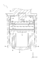
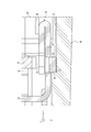
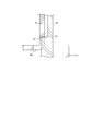
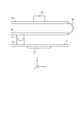
- FIG. 1 is a sectional view taken along the line AA of FIG. It is an enlarged view of the one-dot chain line surrounding part of FIG. It is sectional drawing which shows the structural example which regulates the position by the notch of the side surface part. It is a side view which shows an example of the connection relationship between a connector board, an intermediate board, and an imaging board.
- the image pickup device is required to have both ease of assembly and tightness. According to the image pickup apparatus and the moving body according to the embodiment of the present disclosure, both ease of assembly and sealability can be achieved at the same time.
- the image pickup apparatus 1 includes a lens 58, a holding member 56, an image pickup board 10, a connector board 20, and a housing 50.
- the image pickup apparatus 1 may further include a first sheet metal 30.
- the first sheet metal 30 is also referred to as a sheet metal member.
- the housing 50 has an internal space for accommodating the lens 58, the holding member 56, the image pickup board 10, the connector board 20, and the first sheet metal 30.
- the internal space of the housing 50 is partitioned by the inner wall surface 51 as shown in FIGS. 1 and 2.
- the housing 50 may be configured to include a material such as resin.
- the housing 50 is not limited to the resin, and may be configured to include various materials.
- the image pickup device 1 takes an image of the subject image formed by the lens 58 with the image pickup element 12 mounted on the image pickup substrate 10.
- the image sensor 12 generates image data obtained by capturing an image of a subject.
- the image pickup board 10 is connected to the connector board 20 and outputs image data to the connector board 20.
- the image pickup apparatus 1 is configured to be connectable to the external connector 80 on the connector board 20.
- the image pickup device 1 outputs the image data to the external device via the external connector 80. That is, the image pickup apparatus 1 outputs the image data with the external connector 80 as the output destination.
- the lens 58 is also referred to as an optical member.
- the lens 58 forms an image of a subject image incident on the image pickup apparatus 1.
- the holding member 56 holds the lens 58.
- the lens 58 is joined to the holding member 56.
- the number of lenses 58 is not limited to one, and may be two or more. At least a part of the lens 58 may be replaced with another optical member such as a mirror.
- the lens 58 may be joined to the holding member 56 with, for example, an adhesive.
- the lens 58 may be joined to the holding member 56 by a fitting structure.
- the lens 58 may be joined to the holding member 56 by fastening screws or the like.
- the image sensor 12 is mounted on the image pickup board 10.
- the image pickup device 12 has an image pickup surface.
- the image pickup substrate 10 is arranged so that the image pickup surface of the image pickup device 12 is located on the image pickup surface of the lens 58.
- the image pickup device 12 takes an image of a subject image formed on the image pickup surface by the lens 58.
- the image sensor 12 may be composed of, for example, a CMOS (Complementary Metal Oxide Semiconductor) image sensor, a CCD (Charge Coupled Device), or the like.
- CMOS Complementary Metal Oxide Semiconductor
- CCD Charge Coupled Device
- the image pickup board 10 may be composed of a printed circuit board or the like.
- the image pickup board 10 is joined to the holding member 56.
- the image pickup substrate 10 may be joined to the holding member 56 with, for example, an adhesive.
- the image pickup substrate 10 may be joined to the holding member 56 by a fitting structure.
- the image pickup substrate 10 may be joined to the holding member 56 by fastening screws or the like.
- the connector substrate 20 is located on the opposite side of the lens 58 with respect to the imaging substrate 10. In other words, the connector substrate 20 is located farther than the image pickup substrate 10 when viewed from the lens 58.
- the first sheet metal 30 supports the connector substrate 20 from the negative side of the Z axis.
- the first sheet metal 30 has a base 36 located along the connector substrate 20.
- the first sheet metal 30 has a substrate support portion 38 projecting from the base 36 in the positive direction of the Z axis.
- the board support portion 38 supports the connector board 20 on the positive side of the Z axis. It can be said that the first sheet metal 30 restricts the movement of the connector substrate 20 in the negative direction of the Z axis.
- the first sheet metal 30 has a convex portion 34 protruding from the side surface portion 32 in the positive and negative directions of the X axis.
- the convex portion 34 has a regulated portion 35 configured as a surface on the negative side of the Z axis.
- the housing 50 has a regulating portion 53 formed as a surface on the positive side of the Z axis of a portion protruding from the inner wall surface 51 in the negative direction of the X axis in FIG.
- the first sheet metal 30 regulates the movement of the connector substrate 20 toward the negative side of the Z axis by the substrate support portion 38. Therefore, it can be said that the regulation unit 53 of the housing 50 regulates the movement of the connector board 20 toward the negative direction of the Z axis.
- a notch 35a may be formed in the side surface portion 32 of the first sheet metal 30.
- the side surface portion 32 includes the regulated portion 35 facing the negative direction side of the Z axis. Even in this case, the movement of the first sheet metal 30 in the negative direction is restricted by the contact of the regulated portion 35 with the regulating portion 53 of the housing 50.
- the side surface portion 32 of the first sheet metal 30 has elasticity.
- the side surface portion 32 is configured to be displaceable inward from the inner wall surface 51 of the housing 50 with a portion bent from the base 36 as a fulcrum. Since the side surface portion 32 is displaced inward from the inner wall surface 51, the first sheet metal 30 is easily accommodated in the housing 50 even when the side surface portion 32 has a convex portion 34 protruding toward the inner wall surface 51. .. After the first sheet metal 30 is housed in the housing 50, an elastic force acts in the direction from the side surface portion 32 toward the inner wall surface 51. The elastic force makes it difficult for the first sheet metal 30 to move in the Z-axis direction.
- the housing 50 has an end 52 on the positive side of the Z axis.
- the housing 50 has an opening partitioned by an end 52 on the positive side of the Z axis. It can be said that the internal space of the housing 50 is connected to the outside of the housing 50 through the opening.
- the connector board 20 is housed in the internal space of the housing 50 through the opening.
- the external connector 80 is inserted into the image pickup apparatus 1 in the negative direction of the Z axis, and is connected to the connector substrate 20 through an opening. When the external connector 80 is connected to the image pickup apparatus 1 in the negative direction of the Z axis, the end portion 52 abuts on the external connector 80.
- the internal space of the housing 50 is sealed by the contact between the end portion 52 and the external connector 80.
- the direction in which the external connector 80 is inserted into the image pickup apparatus 1 is also referred to as a first direction.
- the connector board 20 has a first surface facing the positive direction of the Z axis and a second surface located on the opposite side of the first surface and facing the negative direction of the Z axis.
- the connector board 20 has terminals 22.
- the terminal 22 is mounted on the first surface of the connector board 20.
- the terminal 22 is configured to be connectable to the terminal 82 of the external connector 80.
- the terminal 82 of the external connector 80 is connected to the terminal 22 of the connector board 20
- the terminal 22 is pushed by the terminal 82 in the negative direction of the Z axis. Since the movement of the connector board 20 in the negative direction of the Z axis is restricted by the housing 50, the terminal 82 is easily connected to the terminal 22.
- the connector board 20 needs to be connected to the external connector 80 before being housed in the housing 50, and to be housed in the housing 50 after being connected to the external connector 80.
- Such a connection method restricts the assembly work of the image pickup apparatus 1.
- the external connector 80 can be connected while the connector board 20 is housed in the housing 50. As a result, the degree of freedom in the assembly work of the image pickup apparatus 1 is increased.
- the connector board 20 has an end portion 24.
- the inner wall surface 51 of the housing 50 is configured to be separated from the end portion 24 of the connector board 20 by a predetermined distance or more.
- the connector board 20 can move in the X-axis direction and the Y-axis direction within a predetermined distance. That is, the connector board 20 is movably configured within a predetermined range in the direction intersecting the Z axis.
- the dimension of the inner wall surface 51 of the housing 50 is larger than the dimension of the connector substrate 20 in the plan view in the Z-axis direction. In this case, it can be said that the connector substrate 20 is movably configured in a direction intersecting the Z axis, for example, in a predetermined range in the X-axis direction or the Y-axis direction.
- the side surface portion 32 of the first sheet metal 30 is configured to be separated from the end portion 24 of the connector substrate 20 by a predetermined distance or more.
- the connector substrate 20 can move within a predetermined distance in the X-axis direction and the Y-axis direction even if it is surrounded by the side surface portion 32 of the first sheet metal 30 in the X-axis direction and the Y-axis direction.
- the inner dimension of the side surface portion 32 of the first sheet metal 30 is smaller than the dimension of the inner wall surface 51 of the housing 50, but larger than the dimension of the connector substrate 20. ..
- the connector substrate 20 is movably configured within a predetermined range in the direction intersecting the Z axis, for example, the X axis direction or the Y axis direction.
- the image pickup apparatus 1 can be easily assembled.
- the first sheet metal 30 surrounds the connector substrate 20 together with the conductive member 84 of the external connector 80.
- the base 36 (see FIG. 3) of the first sheet metal 30 is positioned so as to cover at least a part of the second surface of the connector substrate 20.
- the side surface portion 32 of the first sheet metal 30 is positioned so as to cover at least a part of the end portion 24 of the connector substrate 20.
- the first sheet metal 30 is made of a conductive material such as metal.
- the first sheet metal 30 is electrically connected to the grounding point of the image pickup apparatus 1.
- the first sheet metal 30 has a side surface portion 32.
- the conductive member 84 is electrically connected to the ground contact point by coming into contact with the side surface portion 32.
- the first sheet metal 30 functions as an electromagnetic shield of the connector substrate 20 together with the conductive member 84.
- the image pickup apparatus 1 may further include a second sheet metal 40.
- the second sheet metal 40 surrounds the image pickup substrate 10.
- the second sheet metal 40 is made of a conductive material such as metal.
- the second sheet metal 40 functions as an electromagnetic shield of the image pickup board 10 by being electrically connected to the grounding point of the image pickup device 1.
- the image pickup apparatus 1 may further include an intermediate substrate 70.
- the second sheet metal 40 surrounds the intermediate substrate 70 together with the first sheet metal 30.
- the first sheet metal 30 and the second sheet metal 40 function as electromagnetic shields of the intermediate substrate 70 by being electrically connected to the grounding point of the image pickup apparatus 1.
- the connector board 20 may be connected to the intermediate board 70 via the flexible board 60.
- the connector board 20 may be connected to the intermediate board 70 via a rigid flexible board.
- the connector board 20 may be connected to the intermediate board 70 via a cable such as a coaxial cable or a flat cable, a harness, or the like.
- the connector board 20 may be connected to the intermediate board 70 via a probe pin such as a pogo pin or a contact terminal. That is, the connector board 20 may be connected to the intermediate board 70 while having mobility with respect to the intermediate board 70. Since the connector board 20 has mobility with respect to the intermediate board 70, when the external connector 80 is connected, the position of the terminal 22 of the connector board 20 easily matches the position of the terminal 82 of the external connector 80. As a result, it is easy to assemble.
- the intermediate board 70 has a board connector 64.
- the imaging board 10 has a board connector 62. It is assumed that the intermediate board 70 and the image pickup board 10 are connected by connecting the board connector 62 and the board connector 64. In this case, the movement of the intermediate substrate 70 is restricted by the imaging substrate 10. Even when the movement of the intermediate substrate 70 is restricted, the connector substrate 20 has mobility with respect to the image pickup substrate 10 because the connector substrate 20 has mobility with respect to the intermediate substrate 70.
- the connector board 20 may be connected to the image pickup board 10 while having mobility with respect to the image pickup board 10.
- the connector board 20 may be connected to the image pickup board 10 via the flexible board 60.
- the connector board 20 may be connected to the image pickup board 10 via a rigid flexible board.
- the connector board 20 may be connected to the image pickup board 10 via a cable such as a coaxial cable or a flat cable, a harness, or the like.
- the connector board 20 may be connected to the image pickup board 10 via a probe pin such as a pogo pin, a contact terminal, or the like.
- the imaging device 1 may be mounted on a moving body.
- Mobile in the present disclosure includes vehicles, ships, and aircraft.
- Vehicles in the present disclosure include, but are not limited to, automobiles and industrial vehicles, and may include railway vehicles, living vehicles, and fixed-wing aircraft traveling on runways.
- Automobiles include, but are not limited to, passenger cars, trucks, buses, motorcycles, trolley buses and the like, and may include other vehicles traveling on the road.
- Industrial vehicles include industrial vehicles for agriculture and construction.
- Industrial vehicles include, but are not limited to, forklifts and golf carts.
- Industrial vehicles for agriculture include, but are not limited to, tractors, cultivators, transplanters, binders, combines, and mowers.
- Industrial vehicles for construction include, but are not limited to, bulldozers, scrapers, excavators, cranes, dump trucks, and road rollers. Vehicles include those that run manually. The classification of vehicles is not limited to the above. For example, an automobile may include an industrial vehicle that can travel on the road and may include the same vehicle in multiple categories. Ships in the present disclosure include marine jets, boats and tankers. Aircraft in the present disclosure include fixed-wing aircraft and rotary-wing aircraft.
- the descriptions such as “first” and “second” are identifiers for distinguishing the configuration.
- the configurations distinguished by the descriptions such as “first” and “second” in the present disclosure can exchange numbers in the configurations.
- the first lens can exchange the identifiers “first” and “second” with the second lens.
- the exchange of identifiers takes place at the same time.
- the configuration is distinguished.
- the identifier may be deleted.
- the configuration with the identifier removed is distinguished by a code. Based solely on the description of identifiers such as “first” and “second” in the present disclosure, it shall not be used as a basis for interpreting the order of the configurations and for the existence of identifiers with smaller numbers.
- the X-axis, Y-axis, and Z-axis are provided for convenience of explanation and may be interchanged with each other.
- the configuration according to the present disclosure has been described using a Cartesian coordinate system composed of the X-axis, the Y-axis, and the Z-axis.
- the positional relationship of each configuration according to the present disclosure is not limited to being orthogonal.
- Image pickup device 10
- Imaging board 12
- Image sensor 20
- Connector board 22: terminal, 24: end
- First sheet metal 32: side surface, 34: convex, 35: regulated, 35a: notch, 36: base, 38: substrate support
- Second sheet metal 50
- Housing 51: inner wall surface, 52: end, 53: regulation part
- Holding member 58
- Lens 60
- Flexible board 62, 64: Board connector
- Intermediate board 80
- External connector 82: Terminal, 84: Conductive member
Landscapes
- Engineering & Computer Science (AREA)
- Multimedia (AREA)
- Signal Processing (AREA)
- Physics & Mathematics (AREA)
- General Physics & Mathematics (AREA)
- Electromagnetism (AREA)
- Mechanical Engineering (AREA)
- Studio Devices (AREA)
- Fittings On The Vehicle Exterior For Carrying Loads, And Devices For Holding Or Mounting Articles (AREA)
- Lens Barrels (AREA)
- Stereoscopic And Panoramic Photography (AREA)
- Camera Bodies And Camera Details Or Accessories (AREA)
Abstract
撮像装置は、撮像基板とコネクタ基板と筐体とを備える。撮像基板は、画像データを生成する撮像素子を有する。コネクタ基板は、撮像基板に対して可動に接続される。コネクタ基板は、画像データの出力先の外部コネクタを第1方向に接続可能に構成される端子を有する。筐体は、撮像基板とコネクタ基板とを収容する。筐体は、第1方向でコネクタ基板の位置を規制する規制部を有する。コネクタ基板は、第1方向に交差する方向の所定範囲内で可動に構成されている。
Description
本出願は、日本国特許出願2019-176166号(2019年9月26日出願)の優先権を主張するものであり、当該出願の開示全体を、ここに参照のために取り込む。
本開示は、撮像装置及び移動体に関する。
カメラの補機モジュールの内部に異物が浸入して補機モジュールの性能が損なわれることがないようにし、更にメンテナンスに優れる補機モジュールの封止構造が知られている(例えば、特許文献1参照)。
本開示の一実施形態に係る撮像装置は、撮像基板と、コネクタ基板と、筐体とを備える。前記撮像基板は、画像データを生成する撮像素子を有する。前記コネクタ基板は、前記撮像基板に対して可動に接続される。前記コネクタ基板は、前記画像データの出力先の外部コネクタを第1方向に接続可能に構成される端子を有する。前記筐体は、前記撮像基板と前記コネクタ基板とを収容する。前記筐体は、前記第1方向で前記コネクタ基板の位置を規制する規制部を有する。前記コネクタ基板は、前記第1方向に交差する方向の所定範囲内で可動に構成されている。
本開示の一実施形態に係る移動体は、撮像装置を搭載する。前記撮像装置は、撮像基板と、コネクタ基板と、筐体とを備える。前記撮像基板は、画像データを生成する撮像素子を有する。前記コネクタ基板は、前記撮像基板に対して可動に接続される。前記コネクタ基板は、前記画像データの出力先の外部コネクタを第1方向に接続可能に構成される端子を有する。前記筐体は、前記撮像基板と前記コネクタ基板とを収容する。前記筐体は、前記第1方向で前記コネクタ基板の位置を規制する規制部を有する。前記コネクタ基板は、前記第1方向に交差する方向の所定範囲内で可動に構成されている。
撮像装置において、組み立ての容易性と密封性との両立が求められる。本開示の一実施形態に係る撮像装置及び移動体によれば、組み立ての容易性と密封性とが両立され得る。
図1から図5までに示されるように、一実施形態に係る撮像装置1は、レンズ58と、保持部材56と、撮像基板10と、コネクタ基板20と、筐体50とを備える。撮像装置1は、第1板金30を更に備えてよい。第1板金30は、板金部材とも称される。
筐体50は、レンズ58、保持部材56、撮像基板10、コネクタ基板20、及び第1板金30を収容する内部空間を有する。筐体50の内部空間は、図1及び図2に示されるように内壁面51によって区画される。筐体50は、例えば樹脂等の材料を含んで構成されてよい。筐体50は、樹脂に限られず、種々の材料を含んで構成されてもよい。
撮像装置1は、レンズ58によって結像される被写体像を撮像基板10に実装されている撮像素子12で撮像する。撮像素子12は、被写体像を撮像した画像データを生成する。撮像基板10は、コネクタ基板20と接続されており、画像データをコネクタ基板20に出力する。撮像装置1は、コネクタ基板20で外部コネクタ80に接続可能に構成される。撮像装置1は、画像データを、外部コネクタ80を介して外部装置に出力する。つまり、撮像装置1は、外部コネクタ80を出力先として画像データを出力する。
レンズ58は、光学部材とも称される。レンズ58は、撮像装置1に入射する被写体像を結像させる。保持部材56は、レンズ58を保持する。レンズ58は、保持部材56に接合される。レンズ58の数は、1枚に限られず、2枚以上であってよい。レンズ58の少なくとも一部は、ミラー等の他の光学部材に置き換えられてよい。レンズ58は、例えば接着剤等によって保持部材56に接合されてよい。レンズ58は、嵌合構造によって保持部材56に接合されてよい。レンズ58は、ねじ等の締結によって保持部材56に接合されてよい。
図2に示されるように、撮像素子12は、撮像基板10に実装されている。撮像素子12は、撮像面を有する。撮像基板10は、撮像素子12の撮像面がレンズ58の結像面に位置するように配置されている。撮像素子12は、レンズ58によって撮像面に結像された被写体像を撮像する。撮像素子12は、例えば、CMOS(Complementary Metal Oxide Semiconductor)イメージセンサ又はCCD(Charge Coupled Device)等で構成されてよい。撮像基板10には、撮像素子12だけでなく、撮像素子12が出力するデータを処理する回路も実装されてよい。撮像基板10は、プリント回路基板等で構成されてよい。
撮像基板10は、保持部材56に接合される。撮像基板10は、例えば接着剤等によって保持部材56に接合されてよい。撮像基板10は、嵌合構造によって保持部材56に接合されてよい。撮像基板10は、ねじ等の締結によって保持部材56に接合されてよい。
図1及び図2に示されるように、コネクタ基板20は、撮像基板10に対してレンズ58の反対側に位置する。言い換えれば、コネクタ基板20は、レンズ58から見て撮像基板10より遠くに位置する。
図1、図2及び図3に示されるように、第1板金30は、コネクタ基板20をZ軸の負の方向の側から支持する。第1板金30は、コネクタ基板20に沿って位置するベース36を有する。第1板金30は、ベース36からZ軸の正の方向に突出する基板支持部38を有する。基板支持部38は、Z軸の正の方向の側でコネクタ基板20を支持する。第1板金30は、コネクタ基板20のZ軸の負の方向の側への移動を規制するともいえる。
図1及び図3に示されるように、第1板金30は、側面部32からX軸の正及び負の方向に突出する凸部34を有する。図3に示されるように、凸部34は、Z軸の負の方向の側の面として構成される被規制部35を有する。筐体50は、図3において内壁面51からX軸の負の方向に突出する部分のZ軸の正の方向の側の面として構成される規制部53を有する。第1板金30の被規制部35が筐体50の規制部53に当接することによって、第1板金30のZ軸の負の方向への移動が規制される。上述の通り、第1板金30は、コネクタ基板20のZ軸の負の方向の側への移動を基板支持部38によって規制する。したがって、筐体50の規制部53は、コネクタ基板20のZ軸の負の方向の側への移動を規制するといえる。
図4に示されるように、第1板金30の側面部32に切欠35aが形成されてよい。側面部32に切欠35aが形成されることによって、側面部32は、Z軸の負の方向の側に向く被規制部35を備える。この場合でも、被規制部35が筐体50の規制部53に当接することによって、第1板金30のZ軸の負の方向への移動が規制される。
第1板金30の側面部32は、弾性を有する。側面部32は、ベース36から屈曲する部分を支点として、筐体50の内壁面51から内側に向けて変位可能に構成されている。側面部32が内壁面51から内側に向けて変位することによって、側面部32が内壁面51に向けて突出する凸部34を有する場合でも、第1板金30が筐体50に収容されやすくなる。第1板金30が筐体50に収容された後、側面部32から内壁面51に向かう方向に弾性力が作用する。弾性力によって、第1板金30がZ軸方向に動きにくくなる。
筐体50は、Z軸の正の方向の側に端部52を有する。筐体50は、Z軸の正の方向の側に端部52で区画されている開口を有する。筐体50の内部空間は、開口を通じて筐体50の外部とつながっているともいえる。コネクタ基板20は、開口を通って、筐体50の内部空間に収容される。外部コネクタ80は、撮像装置1に対してZ軸の負の方向に向けて挿入され、開口を介してコネクタ基板20に接続される。外部コネクタ80が撮像装置1に対してZ軸の負の方向に向けて接続される場合、端部52は、外部コネクタ80に当接する。端部52と外部コネクタ80とが当接することによって、筐体50の内部空間が封止される。外部コネクタ80が撮像装置1に対して挿入される方向は、第1方向とも称される。
コネクタ基板20は、Z軸の正の方向を向く第1面と、第1面の反対側に位置しZ軸の負の方向を向く第2面とを有する。コネクタ基板20は、端子22を有する。端子22は、コネクタ基板20の第1面に実装されている。端子22は、外部コネクタ80の端子82に接続可能に構成されている。コネクタ基板20の端子22に外部コネクタ80の端子82が接続される場合、端子22は、端子82によってZ軸の負の方向に押される。コネクタ基板20のZ軸の負の方向への移動が筐体50によって規制されていることによって、端子82は、端子22に接続されやすくなる。
仮にコネクタ基板20のZ軸の負の方向への移動が規制されていない場合、コネクタ基板20の端子22に外部コネクタ80の端子82を押しつけても接続されにくい。この場合、コネクタ基板20は、筐体50に収容される前に外部コネクタ80に接続され、外部コネクタ80に接続された後に筐体50に収容される必要がある。このような接続方法は、撮像装置1の組み立て作業を制約する。本実施形態によれば、コネクタ基板20が筐体50に収容された状態で外部コネクタ80を接続できる。その結果、撮像装置1の組立作業の自由度が高くなる。
図3に示されるように、コネクタ基板20は、端部24を有する。筐体50の内壁面51は、コネクタ基板20の端部24に対して所定距離以上離れるように構成される。この場合、コネクタ基板20は、X軸方向及びY軸方向に所定距離以内で移動できる。つまり、コネクタ基板20は、Z軸に交差する方向の所定範囲内で可動に構成されている。図1に示されるように、Z軸方向の平面視において、筐体50の内壁面51の寸法は、コネクタ基板20の寸法より大きい。この場合、コネクタ基板20は、Z軸に交差する方向、例えばX軸方向又はY軸方向の所定範囲内で可動に構成されているといえる。
図3に示されるように、第1板金30の側面部32は、コネクタ基板20の端部24に対して所定距離以上離れるように構成される。この場合、コネクタ基板20は、X軸方向及びY軸方向に第1板金30の側面部32に囲まれていても、X軸方向及びY軸方向に所定距離以内で移動できる。図1に示されるように、Z軸方向の平面視において、第1板金30の側面部32の内側の寸法は、筐体50の内壁面51の寸法より小さいものの、コネクタ基板20の寸法より大きい。この場合、コネクタ基板20は、側面部32に囲まれていても、Z軸に交差する方向、例えばX軸方向又はY軸方向の所定範囲内で可動に構成されているといえる。
コネクタ基板20が第1方向に交差する方向に所定範囲内で可動に構成されることで、コネクタ基板20の端子22に外部コネクタ80の端子82が接続される際に、端子22と端子82との位置が合いやすくなる。その結果、撮像装置1の組み立てが容易になる。
図1及び図2に示されるように、第1板金30は、外部コネクタ80の導電部材84とともに、コネクタ基板20を囲う。第1板金30のベース36(図3参照)は、コネクタ基板20の第2面の少なくとも一部を覆うように位置する。第1板金30の側面部32は、コネクタ基板20の端部24の少なくとも一部を覆うように位置する。第1板金30は、金属等の導電性材料で構成される。第1板金30は、撮像装置1の接地点に電気的に接続される。第1板金30は、側面部32を有する。導電部材84は、側面部32と接触することによって接地点に電気的に接続される。第1板金30は、導電部材84とともにコネクタ基板20の電磁シールドとして機能する。
図2に示されるように、撮像装置1は、第2板金40を更に備えてよい。第2板金40は、撮像基板10を囲う。第2板金40は、金属等の導電性材料で構成される。第2板金40は、撮像装置1の接地点に電気的に接続されることによって撮像基板10の電磁シールドとして機能する。
撮像装置1は、中間基板70を更に備えてよい。第2板金40は、第1板金30とともに中間基板70を囲う。第1板金30及び第2板金40は、撮像装置1の接地点に電気的に接続されることによって中間基板70の電磁シールドとして機能する。
図5に示されるように、コネクタ基板20は、フレキシブル基板60を介して中間基板70に接続されてよい。コネクタ基板20は、リジッドフレキシブル基板を介して中間基板70に接続されてもよい。コネクタ基板20は、同軸ケーブル若しくはフラットケーブル等のケーブル又はハーネス等を介して中間基板70に接続されてもよい。コネクタ基板20は、ポゴピン等のプローブピン又はコンタクト端子等を介して中間基板70に接続されてもよい。つまり、コネクタ基板20は、中間基板70に対する可動性を有しつつ、中間基板70に接続されてよい。コネクタ基板20が中間基板70に対する可動性を有することによって、外部コネクタ80が接続される際に、コネクタ基板20の端子22の位置が外部コネクタ80の端子82の位置に合いやすくなる。その結果、組み立てが容易になる。
図5に示されるように、中間基板70は、ボードコネクタ64を有する。撮像基板10は、ボードコネクタ62を有する。ボードコネクタ62とボードコネクタ64とが接続されることによって、中間基板70と撮像基板10とが接続されるとする。この場合、中間基板70は、撮像基板10によって移動が制限される。中間基板70の移動が制限される場合であっても、コネクタ基板20が中間基板70に対して可動性を有することによって、コネクタ基板20は、撮像基板10に対して可動性を有する。
撮像装置1が中間基板70を備えない場合、コネクタ基板20は、撮像基板10に対する可動性を有しつつ、撮像基板10に接続されてよい。例えば、コネクタ基板20は、フレキシブル基板60を介して撮像基板10に接続されてもよい。コネクタ基板20は、リジッドフレキシブル基板を介して撮像基板10に接続されてもよい。コネクタ基板20は、同軸ケーブル若しくはフラットケーブル等のケーブル又はハーネス等を介して撮像基板10に接続されてもよい。コネクタ基板20は、ポゴピン等のプローブピン又はコンタクト端子等を介して撮像基板10に接続されてもよい。
本開示に係る撮像装置1は、移動体に搭載されてよい。本開示における「移動体」には、車両、船舶、航空機を含む。本開示における「車両」には、自動車及び産業車両を含むが、これに限られず、鉄道車両及び生活車両、滑走路を走行する固定翼機を含めてよい。自動車は、乗用車、トラック、バス、二輪車、及びトロリーバス等を含むがこれに限られず、道路上を走行する他の車両を含んでよい。産業車両は、農業及び建設向けの産業車両を含む。産業車両には、フォークリフト、及びゴルフカートを含むがこれに限られない。農業向けの産業車両には、トラクター、耕耘機、移植機、バインダー、コンバイン、及び芝刈り機を含むが、これに限られない。建設向けの産業車両には、ブルドーザー、スクレーバー、ショベルカー、クレーン車、ダンプカー、及びロードローラを含むが、これに限られない。車両は、人力で走行するものを含む。なお、車両の分類は、上述に限られない。例えば、自動車には、道路を走行可能な産業車両を含んでよく、複数の分類に同じ車両が含まれてよい。本開示における船舶には、マリンジェット、ボート、タンカーを含む。本開示における航空機には、固定翼機、回転翼機を含む。
本開示に係る実施形態について説明する図は模式的なものである。図面上の寸法比率等は、現実のものとは必ずしも一致していない。
本開示に係る実施形態について、諸図面及び実施例に基づき説明してきたが、当業者であれば本開示に基づき種々の変形又は改変を行うことが可能であることに注意されたい。従って、これらの変形又は改変は本開示の範囲に含まれることに留意されたい。例えば、各構成部又は各ステップなどに含まれる機能などは論理的に矛盾しないように再配置可能であり、複数の構成部又はステップなどを1つに組み合わせたり、或いは分割したりすることが可能である。本開示に係る実施形態について装置を中心に説明してきたが、本開示に係る実施形態は装置の各構成部が実行するステップを含む方法としても実現し得るものである。本開示に係る実施形態は装置が備えるプロセッサにより実行される方法、プログラム、又はプログラムを記録した記憶媒体としても実現し得るものである。本開示の範囲にはこれらも包含されるものと理解されたい。
本開示において「第1」及び「第2」等の記載は、当該構成を区別するための識別子である。本開示における「第1」及び「第2」等の記載で区別された構成は、当該構成における番号を交換することができる。例えば、第1レンズは、第2レンズと識別子である「第1」と「第2」とを交換することができる。識別子の交換は同時に行われる。識別子の交換後も当該構成は区別される。識別子は削除してよい。識別子を削除した構成は、符号で区別される。本開示における「第1」及び「第2」等の識別子の記載のみに基づいて、当該構成の順序の解釈、小さい番号の識別子が存在することの根拠に利用してはならない。
本開示において、X軸、Y軸、及びZ軸は、説明の便宜上設けられたものであり、互いに入れ替えられてよい。本開示に係る構成は、X軸、Y軸、及びZ軸によって構成される直交座標系を用いて説明されてきた。本開示に係る各構成の位置関係は、直交関係にあると限定されるものではない。
1 撮像装置
10 撮像基板
12 撮像素子
20 コネクタ基板(22:端子、24:端部)
30 第1板金(32:側面部、34:凸部、35:被規制部、35a:切欠、36:ベース、38:基板支持部)
40 第2板金
50 筐体(51:内壁面、52:端部、53:規制部)
56 保持部材
58 レンズ
60 フレキシブル基板(62、64:ボードコネクタ)
70 中間基板
80 外部コネクタ(82:端子、84:導電部材)
10 撮像基板
12 撮像素子
20 コネクタ基板(22:端子、24:端部)
30 第1板金(32:側面部、34:凸部、35:被規制部、35a:切欠、36:ベース、38:基板支持部)
40 第2板金
50 筐体(51:内壁面、52:端部、53:規制部)
56 保持部材
58 レンズ
60 フレキシブル基板(62、64:ボードコネクタ)
70 中間基板
80 外部コネクタ(82:端子、84:導電部材)
Claims (10)
- 画像データを生成する撮像素子を有する撮像基板と、
前記撮像基板に対して可動に接続され、前記画像データの出力先の外部コネクタを第1方向に接続可能に構成される端子を有するコネクタ基板と、
前記撮像基板と前記コネクタ基板とを収容する筐体と
を備え、
前記筐体は、前記第1方向で前記コネクタ基板の位置を規制する規制部を有し、
前記コネクタ基板は、前記第1方向に交差する方向の所定範囲内で可動に構成されている、撮像装置。 - 前記筐体は、前記撮像基板と前記コネクタ基板とを収容する内部空間を区画する内壁面を有し、
前記第1方向の平面視において、前記内壁面の寸法は、前記コネクタ基板の寸法より大きい、請求項1に記載の撮像装置。 - 板金部材を更に備え、
前記コネクタ基板は、前記外部コネクタに接続可能に構成される端子が実装されている第1面と、前記第1面の反対側に位置する第2面とを有し、
前記板金部材は、前記コネクタ基板の第2面の少なくとも一部を覆うように位置し、
前記規制部は、前記板金部材の位置を前記第1方向に沿って規制する、請求項2に記載の撮像装置。 - 前記板金部材は、前記コネクタ基板の端部の少なくとも一部を覆うように位置する側面部を有し、
前記側面部は、弾性を有し、前記内壁面に対して変位可能に構成されている、請求項3に記載の撮像装置。 - 前記第1方向の平面視において、前記板金部材の側面部の内側の寸法は、前記内壁面の寸法より小さいものの前記コネクタ基板の寸法より大きい、請求項4に記載の撮像装置。
- 前記筐体は、前記内部空間から前記筐体の外部につながる開口を区画する端部を有し、
前記端部は、前記外部コネクタが前記コネクタ基板に接続された場合に、前記外部コネクタと当接して前記開口が封止されるように構成されている、請求項2に記載の撮像装置。 - 前記筐体は、前記内部空間から前記筐体の外部につながる開口を区画する端部を有し、
前記端部は、前記外部コネクタが前記コネクタ基板に接続された場合に、前記外部コネクタと当接して前記開口が封止されるように構成されている、請求項3に記載の撮像装置。 - 前記筐体は、前記内部空間から前記筐体の外部につながる開口を区画する端部を有し、
前記端部は、前記外部コネクタが前記コネクタ基板に接続された場合に、前記外部コネクタと当接して前記開口が封止されるように構成されている、請求項4に記載の撮像装置。 - 前記筐体は、前記内部空間から前記筐体の外部につながる開口を区画する端部を有し、
前記端部は、前記外部コネクタが前記コネクタ基板に接続された場合に、前記外部コネクタと当接して前記開口が封止されるように構成されている、請求項5に記載の撮像装置。 - 撮像装置を搭載し、
前記撮像装置は、
画像データを生成する撮像素子を有する撮像基板と、
前記撮像基板に対して可動に接続され、前記画像データの出力先の外部コネクタを第1方向に接続可能に構成される端子を有するコネクタ基板と、
前記撮像基板と前記コネクタ基板とを収容する筐体と
を備え、
前記筐体は、前記第1方向で前記コネクタ基板の位置を規制する規制部を有し、
前記コネクタ基板は、前記第1方向に交差する方向の所定範囲内で可動に構成されている、移動体。
Priority Applications (3)
| Application Number | Priority Date | Filing Date | Title |
|---|---|---|---|
| US17/754,044 US12028591B2 (en) | 2019-09-26 | 2020-09-08 | Imaging apparatus and mobile object |
| CN202080067688.9A CN114450930B (zh) | 2019-09-26 | 2020-09-08 | 拍摄装置以及移动体 |
| EP20870200.1A EP4037302B1 (en) | 2019-09-26 | 2020-09-08 | Imaging device and moving body |
Applications Claiming Priority (2)
| Application Number | Priority Date | Filing Date | Title |
|---|---|---|---|
| JP2019176166A JP7449666B2 (ja) | 2019-09-26 | 2019-09-26 | 撮像装置及び移動体 |
| JP2019-176166 | 2019-09-26 |
Publications (1)
| Publication Number | Publication Date |
|---|---|
| WO2021059964A1 true WO2021059964A1 (ja) | 2021-04-01 |
Family
ID=75165716
Family Applications (1)
| Application Number | Title | Priority Date | Filing Date |
|---|---|---|---|
| PCT/JP2020/033938 Ceased WO2021059964A1 (ja) | 2019-09-26 | 2020-09-08 | 撮像装置及び移動体 |
Country Status (5)
| Country | Link |
|---|---|
| US (1) | US12028591B2 (ja) |
| EP (1) | EP4037302B1 (ja) |
| JP (1) | JP7449666B2 (ja) |
| CN (1) | CN114450930B (ja) |
| WO (1) | WO2021059964A1 (ja) |
Families Citing this family (2)
| Publication number | Priority date | Publication date | Assignee | Title |
|---|---|---|---|---|
| KR20230020242A (ko) * | 2021-08-03 | 2023-02-10 | 엘지이노텍 주식회사 | 카메라 모듈 |
| JP2026068633A (ja) * | 2024-10-10 | 2026-04-22 | 京セラ株式会社 | 撮像装置 |
Citations (3)
| Publication number | Priority date | Publication date | Assignee | Title |
|---|---|---|---|---|
| JP2002231375A (ja) | 2001-01-30 | 2002-08-16 | Yazaki Corp | 補機モジュールの封止構造 |
| JP2011259101A (ja) * | 2010-06-07 | 2011-12-22 | Ricoh Co Ltd | 撮像装置 |
| JP2018137401A (ja) * | 2017-02-23 | 2018-08-30 | リズム時計工業株式会社 | 情報処理装置、カメラ及びカメラ装置 |
Family Cites Families (4)
| Publication number | Priority date | Publication date | Assignee | Title |
|---|---|---|---|---|
| CN102326382B (zh) * | 2010-03-10 | 2016-04-13 | Smk株式会社 | 摄像机模块 |
| JP5187328B2 (ja) * | 2010-03-12 | 2013-04-24 | オムロン株式会社 | 計測処理用撮像装置 |
| JPWO2012104929A1 (ja) * | 2011-01-31 | 2014-07-03 | パナソニック株式会社 | 撮像装置 |
| JP2018085614A (ja) * | 2016-11-23 | 2018-05-31 | 日本電産コパル株式会社 | 撮像装置 |
-
2019
- 2019-09-26 JP JP2019176166A patent/JP7449666B2/ja active Active
-
2020
- 2020-09-08 CN CN202080067688.9A patent/CN114450930B/zh active Active
- 2020-09-08 WO PCT/JP2020/033938 patent/WO2021059964A1/ja not_active Ceased
- 2020-09-08 EP EP20870200.1A patent/EP4037302B1/en active Active
- 2020-09-08 US US17/754,044 patent/US12028591B2/en active Active
Patent Citations (3)
| Publication number | Priority date | Publication date | Assignee | Title |
|---|---|---|---|---|
| JP2002231375A (ja) | 2001-01-30 | 2002-08-16 | Yazaki Corp | 補機モジュールの封止構造 |
| JP2011259101A (ja) * | 2010-06-07 | 2011-12-22 | Ricoh Co Ltd | 撮像装置 |
| JP2018137401A (ja) * | 2017-02-23 | 2018-08-30 | リズム時計工業株式会社 | 情報処理装置、カメラ及びカメラ装置 |
Non-Patent Citations (1)
| Title |
|---|
| See also references of EP4037302A4 |
Also Published As
| Publication number | Publication date |
|---|---|
| CN114450930A (zh) | 2022-05-06 |
| JP7449666B2 (ja) | 2024-03-14 |
| EP4037302A1 (en) | 2022-08-03 |
| CN114450930B (zh) | 2024-08-20 |
| US20220385790A1 (en) | 2022-12-01 |
| JP2021057629A (ja) | 2021-04-08 |
| US12028591B2 (en) | 2024-07-02 |
| EP4037302A4 (en) | 2023-08-30 |
| EP4037302B1 (en) | 2025-04-23 |
Similar Documents
| Publication | Publication Date | Title |
|---|---|---|
| US12568291B2 (en) | Electronic device, imaging apparatus, and mobile body | |
| WO2021059965A1 (ja) | 撮像装置及び移動体 | |
| WO2021059964A1 (ja) | 撮像装置及び移動体 | |
| WO2020217908A1 (ja) | 電子機器、撮像装置、及び移動体 | |
| JP2025070210A (ja) | 車載用カメラ | |
| JP6912398B2 (ja) | 固定構造、撮像装置および移動体 | |
| JP2022000716A (ja) | 撮像装置及び移動体 | |
| US11543614B2 (en) | Imaging apparatus, mobile object, and manufacturing method | |
| US20260036807A1 (en) | Vehicular camera | |
| WO2020189505A1 (ja) | 電子機器、撮像装置、および移動体 | |
| US20250274646A1 (en) | Vehicular camera | |
| WO2019004006A1 (ja) | 撮像装置、撮像装置の製造方法、及び移動体 | |
| JP2025519278A (ja) | 車両用カメラのハウジング、車両用カメラ、および車両 | |
| JP2020145489A (ja) | 撮像装置、撮像装置の製造方法、及び移動体 |
Legal Events
| Date | Code | Title | Description |
|---|---|---|---|
| 121 | Ep: the epo has been informed by wipo that ep was designated in this application |
Ref document number: 20870200 Country of ref document: EP Kind code of ref document: A1 |
|
| NENP | Non-entry into the national phase |
Ref country code: DE |
|
| ENP | Entry into the national phase |
Ref document number: 2020870200 Country of ref document: EP Effective date: 20220426 |
|
| WWG | Wipo information: grant in national office |
Ref document number: 2020870200 Country of ref document: EP |