WO2021060935A1 - 무선 통신 시스템에서 크로스 슬롯 스케쥴링 방법 및 장치 - Google Patents
무선 통신 시스템에서 크로스 슬롯 스케쥴링 방법 및 장치 Download PDFInfo
- Publication number
- WO2021060935A1 WO2021060935A1 PCT/KR2020/013131 KR2020013131W WO2021060935A1 WO 2021060935 A1 WO2021060935 A1 WO 2021060935A1 KR 2020013131 W KR2020013131 W KR 2020013131W WO 2021060935 A1 WO2021060935 A1 WO 2021060935A1
- Authority
- WO
- WIPO (PCT)
- Prior art keywords
- minimum offset
- terminal
- dci
- time
- base station
- Prior art date
- Legal status (The legal status is an assumption and is not a legal conclusion. Google has not performed a legal analysis and makes no representation as to the accuracy of the status listed.)
- Ceased
Links
Images


Classifications
-
- H—ELECTRICITY
- H04—ELECTRIC COMMUNICATION TECHNIQUE
- H04L—TRANSMISSION OF DIGITAL INFORMATION, e.g. TELEGRAPHIC COMMUNICATION
- H04L5/00—Arrangements affording multiple use of the transmission path
- H04L5/003—Arrangements for allocating sub-channels of the transmission path
- H04L5/0053—Allocation of signalling, i.e. of overhead other than pilot signals
-
- H—ELECTRICITY
- H04—ELECTRIC COMMUNICATION TECHNIQUE
- H04W—WIRELESS COMMUNICATION NETWORKS
- H04W72/00—Local resource management
- H04W72/20—Control channels or signalling for resource management
- H04W72/23—Control channels or signalling for resource management in the downlink direction of a wireless link, i.e. towards a terminal
-
- H—ELECTRICITY
- H04—ELECTRIC COMMUNICATION TECHNIQUE
- H04L—TRANSMISSION OF DIGITAL INFORMATION, e.g. TELEGRAPHIC COMMUNICATION
- H04L5/00—Arrangements affording multiple use of the transmission path
- H04L5/0001—Arrangements for dividing the transmission path
- H04L5/0003—Two-dimensional division
- H04L5/0005—Time-frequency
- H04L5/0007—Time-frequency the frequencies being orthogonal, e.g. OFDM(A) or DMT
-
- H—ELECTRICITY
- H04—ELECTRIC COMMUNICATION TECHNIQUE
- H04L—TRANSMISSION OF DIGITAL INFORMATION, e.g. TELEGRAPHIC COMMUNICATION
- H04L5/00—Arrangements affording multiple use of the transmission path
- H04L5/0001—Arrangements for dividing the transmission path
- H04L5/0003—Two-dimensional division
- H04L5/0005—Time-frequency
- H04L5/0007—Time-frequency the frequencies being orthogonal, e.g. OFDM(A) or DMT
- H04L5/001—Time-frequency the frequencies being orthogonal, e.g. OFDM(A) or DMT the frequencies being arranged in component carriers
-
- H—ELECTRICITY
- H04—ELECTRIC COMMUNICATION TECHNIQUE
- H04L—TRANSMISSION OF DIGITAL INFORMATION, e.g. TELEGRAPHIC COMMUNICATION
- H04L5/00—Arrangements affording multiple use of the transmission path
- H04L5/0091—Signalling for the administration of the divided path, e.g. signalling of configuration information
- H04L5/0094—Indication of how sub-channels of the path are allocated
-
- H—ELECTRICITY
- H04—ELECTRIC COMMUNICATION TECHNIQUE
- H04W—WIRELESS COMMUNICATION NETWORKS
- H04W72/00—Local resource management
- H04W72/12—Wireless traffic scheduling
-
- H—ELECTRICITY
- H04—ELECTRIC COMMUNICATION TECHNIQUE
- H04W—WIRELESS COMMUNICATION NETWORKS
- H04W52/00—Power management, e.g. Transmission Power Control [TPC] or power classes
- H04W52/02—Power saving arrangements
- H04W52/0209—Power saving arrangements in terminal devices
- H04W52/0212—Power saving arrangements in terminal devices managed by the network, e.g. network or access point is leader and terminal is follower
- H04W52/0216—Power saving arrangements in terminal devices managed by the network, e.g. network or access point is leader and terminal is follower using a pre-established activity schedule, e.g. traffic indication frame
-
- H—ELECTRICITY
- H04—ELECTRIC COMMUNICATION TECHNIQUE
- H04W—WIRELESS COMMUNICATION NETWORKS
- H04W52/00—Power management, e.g. Transmission Power Control [TPC] or power classes
- H04W52/02—Power saving arrangements
- H04W52/0209—Power saving arrangements in terminal devices
- H04W52/0225—Power saving arrangements in terminal devices using monitoring of external events, e.g. the presence of a signal
- H04W52/0229—Power saving arrangements in terminal devices using monitoring of external events, e.g. the presence of a signal where the received signal is a wanted signal
-
- H—ELECTRICITY
- H04—ELECTRIC COMMUNICATION TECHNIQUE
- H04W—WIRELESS COMMUNICATION NETWORKS
- H04W52/00—Power management, e.g. Transmission Power Control [TPC] or power classes
- H04W52/02—Power saving arrangements
- H04W52/0209—Power saving arrangements in terminal devices
- H04W52/0251—Power saving arrangements in terminal devices using monitoring of local events, e.g. events related to user activity
- H04W52/0258—Power saving arrangements in terminal devices using monitoring of local events, e.g. events related to user activity controlling an operation mode according to history or models of usage information, e.g. activity schedule or time of day
Definitions
- the present disclosure relates to a method and apparatus for cross-slot scheduling in a wireless communication system.
- the 5G communication system or the pre-5G communication system is called a communication system after a 4G network (Beyond 4G Network) or a system after an LTE system (Post LTE).
- the 5G communication system is being considered for implementation in the ultra-high frequency (mmWave) band (eg, the 60 giga (80 GHz) band).
- 5G communication systems include beamforming, massive MIMO, and Full Dimensional MIMO (FD-MIMO). ), array antenna, analog beam-forming, and large scale antenna technologies are being discussed.
- FD-MIMO Full Dimensional MIMO
- array antenna analog beam-forming, and large scale antenna technologies are being discussed.
- cloud RAN cloud radio access network
- D2D Device to Device communication
- wireless backhaul moving network
- CoMP Coordinatd Multi-Points
- interference cancellation And other technologies are being developed.
- ACM advanced coding modulation
- FQAM Hybrid FSK and QAM Modulation
- SWSC Small Cellular Cellular System
- FBMC Filter Bank Multi Carrier
- NOMA non-orthogonal multiple access
- SCMA sparse code multiple access
- IoT Internet of Things
- M2M Machine Type Communication
- MTC Machine Type Communication
- 5G communication system 5G communication system or New Radio (NR)
- technologies such as sensor network, machine to machine (M2M), and machine type communication (MTC) are implemented by techniques such as beamforming, MIMO, and array antenna, which are 5G communication technologies.
- M2M machine to machine
- MTC machine type communication
- cloud RAN cloud radio access network
- the disclosed embodiment is to provide an apparatus and method capable of effectively providing a service in a mobile communication system.
- a method of a terminal in a communication system for solving the above problems is, downlink control information (DCI) including a minimum offset indication field indicating a first minimum offset from a base station.
- DCI downlink control information
- Receiving ); Checking an application delay time for applying the first minimum offset; And transmitting and receiving data to and from the base station based on the first minimum offset after the application delay time from the time when the DCI is received, and the first minimum offset during the application delay time from the time when the DCI is received.
- DCI including a minimum offset indication field indicating a minimum offset different from that of the base station may not be received from the base station.
- the application delay time is based on a subcarrier spacing of a physical downlink control channel (PDCCH), a subcarrier spacing of a physical downlink shared channel (PDSCH), and a subcarrier spacing of an activated bandwidth part (BWP). Can be confirmed.
- PDCCH physical downlink control channel
- PDSCH physical downlink shared channel
- BWP activated bandwidth part
- the method includes: checking a monitoring period of a search space set related to the first minimum offset; And receiving a DCI including the minimum offset indication field based on a monitoring period of the search space set related to the first minimum offset.
- the monitoring period of the search space set related to the first minimum offset may be greater than or equal to a specific value.
- a method of a base station of a communication system includes: transmitting downlink control information (DCI) including a minimum offset indication field indicating a first minimum offset to a terminal; Checking an application delay time for applying the first minimum offset; And transmitting and receiving data with the terminal based on the first minimum offset after the application delay time from the time when the DCI is transmitted, and the first minimum offset during the application delay time from the time when the DCI is transmitted.
- DCI including a minimum offset indication field indicating a minimum offset different from that of the terminal may not be transmitted to the terminal.
- a terminal of a communication system includes: a transmission/reception unit; And downlink control information (DCI: downlink control information) including a minimum offset indication field indicating a first minimum offset from the base station, and checking an application delay time for applying the first minimum offset, and the DCI And a control unit configured to transmit and receive data to and from the base station based on the first minimum offset after the application delay time from a time point at which the DCI is received, and the first minimum offset and during the application delay time from the time point at which the DCI is received.
- DCI including a minimum offset indication field indicating another minimum offset may not be received from the base station.
- a base station of a communication system includes: a transceiver; And downlink control information (DCI: downlink control information) including a minimum offset indication field indicating the first minimum offset to the terminal, and the application delay time for applying the first minimum offset is checked, and the DCI And a control unit configured to transmit and receive data to and from the terminal based on the first minimum offset after the application delay time from the time of transmission, and the first minimum offset and the first minimum offset during the application delay time from the time when the DCI is transmitted.
- DCI including a minimum offset indication field indicating another minimum offset may not be transmitted to the terminal.
- the disclosed embodiment provides an apparatus and method capable of effectively providing a service in a mobile communication system.
- FIG. 1 is a diagram illustrating a basic structure of a time-frequency domain in 5G according to an embodiment of the present disclosure.
- FIG. 2 is a diagram illustrating a structure of a frame, a subframe, and a slot in 5G according to an embodiment of the present disclosure.
- 3 is a diagram illustrating an example of setting a bandwidth portion in 5G according to an embodiment of the present disclosure.
- FIG. 4 is a diagram illustrating an example of setting a control region of a downlink control channel in 5G according to an embodiment of the present disclosure.
- 5 is a diagram illustrating a structure of a downlink control channel in 5G according to an embodiment of the present disclosure.
- FIG. 6 is a diagram illustrating an example of a DRX operation in 5G according to an embodiment of the present disclosure.
- FIG. 7 is a diagram illustrating an example of a cross-slot scheduling method according to an embodiment of the present disclosure.
- FIG. 8 is a diagram illustrating an example of a cross-slot scheduling method according to an embodiment of the present disclosure.
- FIG. 9 is a diagram illustrating an example of a terminal operation according to an embodiment of the present disclosure.
- FIG. 10 is a diagram illustrating an example of a terminal operation according to another embodiment of the present disclosure.
- FIG. 11 is a diagram illustrating an example of a terminal operation according to another embodiment of the present disclosure.
- 12A is a diagram illustrating an example of a terminal operation according to another embodiment of the present disclosure.
- 12B is a diagram illustrating an example of a terminal operation according to another embodiment of the present disclosure.
- FIG. 13 is a block diagram illustrating a structure of a terminal according to an embodiment of the present disclosure.
- FIG. 14 is a block diagram illustrating a structure of a base station according to an embodiment of the present disclosure.
- the base station is a subject that performs resource allocation of the terminal, and may be at least one of a gNode B, an eNode B, a Node B, a base station (BS), a radio access unit, a base station controller, or a node on a network.
- the terminal may include a user equipment (UE), a mobile station (MS), a cellular phone, a smart phone, a computer, or a multimedia system capable of performing a communication function.
- a downlink (DL) refers to a radio transmission path of a signal transmitted from a base station to a terminal
- an uplink (UL) refers to a radio transmission path of a signal transmitted from the terminal to the base station.
- LTE or LTE-A system may be described below as an example, but the embodiment of the present disclosure may be applied to other communication systems having a similar technical background or channel type.
- 5G mobile communication technology (5G, new radio, NR) developed after LTE-A may be included, and the following 5G may be a concept including existing LTE, LTE-A and other similar services.
- 5G new radio
- the present disclosure may be applied to other communication systems through some modifications without significantly departing from the scope of the present disclosure as a judgment of a person having skilled technical knowledge.
- each block of the flowchart diagrams and combinations of the flowchart diagrams may be executed by computer program instructions. Since these computer program instructions can be mounted on the processor of a general purpose computer, special purpose computer or other programmable data processing equipment, the instructions executed by the processor of the computer or other programmable data processing equipment are described in the flowchart block(s). It creates a means to perform functions.
- These computer program instructions can also be stored in computer-usable or computer-readable memory that can be directed to a computer or other programmable data processing equipment to implement a function in a particular way, so that the computer-usable or computer-readable memory It is also possible for the instructions stored in the flow chart to produce an article of manufacture containing instruction means for performing the functions described in the flowchart block(s). Since computer program instructions can also be mounted on a computer or other programmable data processing equipment, a series of operating steps are performed on a computer or other programmable data processing equipment to create a computer-executable process to create a computer or other programmable data processing equipment. It is also possible for instructions to perform processing equipment to provide steps for executing the functions described in the flowchart block(s).
- each block may represent a module, segment, or part of code that contains one or more executable instructions for executing the specified logical function(s).
- the functions mentioned in the blocks may occur out of order. For example, two blocks shown in succession may in fact be executed substantially simultaneously, or the blocks may sometimes be executed in reverse order depending on the corresponding function.
- the term' ⁇ unit' used in this embodiment refers to software or hardware components such as field programmable gate array (FPGA) or application specific integrated circuit (ASIC), and' ⁇ unit' performs certain roles. do.
- The' ⁇ unit' may be configured to be in an addressable storage medium, or may be configured to reproduce one or more processors.
- ' ⁇ unit' refers to components such as software components, object-oriented software components, class components, and task components, processes, functions, properties, and procedures. , Subroutines, segments of program code, drivers, firmware, microcode, circuits, data, databases, data structures, tables, arrays, and variables.
- components and functions provided in the' ⁇ units' may be combined into a smaller number of elements and' ⁇ units', or may be further separated into additional elements and' ⁇ units'.
- components and' ⁇ units' may be implemented to play one or more CPUs in a device or a security multimedia card.
- the' ⁇ unit' may include one or more processors.
- the wireless communication system deviated from the initial voice-oriented service, for example, 3GPP HSPA (High Speed Packet Access), LTE (Long Term Evolution or E-UTRA (Evolved Universal Terrestrial Radio Access)), LTE-Advanced. (LTE-A), LTE-Pro, 3GPP2's High Rate Packet Data (HRPD), UMB (Ultra Mobile Broadband), and IEEE's 802.16e. It is evolving into a communication system.
- 3GPP HSPA High Speed Packet Access
- LTE-A LTE-Advanced.
- LTE-Pro LTE-Pro
- HRPD High Rate Packet Data
- UMB UserMB
- the LTE system employs an Orthogonal Frequency Division Multiplexing (OFDM) scheme in a downlink (DL), and a single carrier frequency division multiplexing (SC-FDMA) scheme in an uplink (UL). Access) method is adopted.
- Uplink refers to a radio link through which a terminal (UE (User Equipment) or MS (Mobile Station)) transmits data or control signals to a base station (eNode B or base station (BS)), and downlink refers to a base station It means a wireless link that transmits data or control signals.
- UE User Equipment
- MS Mobile Station
- eNode B base station
- BS base station
- eMBB enhanced Mobile Broadband
- mMTC massive Machine Type Communication
- URLLC Ultra Reliability Low Latency Communciation
- eMBB aims to provide a more improved data rate than the data rate supported by the existing LTE, LTE-A, or LTE-Pro.
- eMBB in a 5G communication system, eMBB must be able to provide a maximum transmission rate of 20 Gbps in downlink and 10 Gbps in uplink from the viewpoint of one base station.
- the 5G communication system must provide the maximum transmission rate and at the same time provide the increased user perceived data rate of the terminal.
- it is required to improve various transmission/reception technologies including a more advanced multi-antenna (Multi Input Multi Output, MIMO) transmission technology.
- MIMO Multi Input Multi Output
- the 5G communication system uses a wider frequency bandwidth than 20MHz in the 3 ⁇ 6GHz or 6GHz or higher frequency band, so the data required by the 5G communication system It can satisfy the transmission speed.
- mMTC is being considered to support application services such as Internet of Things (IoT) in 5G communication systems.
- IoT Internet of Things
- mMTC is required to support access to a large-scale terminal within a cell, improve terminal coverage, improved battery time, and reduce terminal cost.
- IoT is attached to various sensors and various devices to provide communication functions, so it must be able to support a large number of terminals (for example, 1,000,000 terminals/km2) within a cell.
- the terminal supporting mMTC is highly likely to be located in a shaded area not covered by the cell, such as the basement of a building due to the nature of the service, it may require wider coverage compared to other services provided by the 5G communication system.
- a terminal supporting mMTC must be configured as a low-cost terminal, and since it is difficult to frequently exchange the battery of the terminal, a very long battery life time such as 10 to 15 years may be required.
- URLLC it is a cellular-based wireless communication service used for a mission-critical purpose. For example, remote control of robots or machinery, industrial automation, unmaned aerial vehicles, remote health care, emergency situations. Services used for emergency alerts, etc. can be considered. Therefore, the communication provided by URLLC must provide very low latency and very high reliability. For example, a service supporting URLLC must satisfy an air interface latency of less than 0.5 milliseconds, and at the same time have a requirement of a packet error rate of 10 -5 or less.
- a 5G system must provide a smaller Transmit Time Interval (TTI) than other services, and at the same time, it is a design that allocates a wide resource in the frequency band to secure the reliability of the communication link. Requirements may be required.
- TTI Transmit Time Interval
- the three services of 5G namely eMBB, URLLC, and mMTC, can be multiplexed and transmitted in one system.
- different transmission/reception techniques and transmission/reception parameters may be used between services in order to satisfy different requirements of each service.
- 5G is not limited to the three services described above.
- FIG. 1 is a diagram showing a basic structure of a time-frequency domain, which is a radio resource domain in which data or control channels are transmitted in a 5G system.
- the horizontal axis represents the time domain and the vertical axis represents the frequency domain.
- the basic unit of a resource in the time and frequency domain is a resource element (RE, 101), defined as 1 Orthogonal Frequency Division Multiplexing (OFDM) symbol 102 on the time axis and 1 subcarrier 103 on the frequency axis. Can be.
- OFDM Orthogonal Frequency Division Multiplexing
- the frequency domain (For example, 12) consecutive REs may constitute one resource block (RB, 104).
- FIG. 2 is a diagram illustrating a slot structure considered in a 5G system.
- One frame 200 may be defined as 10 ms.
- One subframe 201 may be defined as 1 ms, and thus, one frame 200 may consist of a total of 10 subframes 201.
- One subframe 201 may be composed of one or a plurality of slots 202, 203, and the number of slots 202, 203 per subframe 201 is a set value ⁇ (204, 205) for the subcarrier interval. ) May vary. In the example of FIG.
- bandwidth part (BWP) setting in a 5G communication system will be described in detail with reference to the drawings.
- 3 is a diagram illustrating an example of setting a bandwidth portion in a 5G communication system.
- the base station may set one or a plurality of bandwidth portions to the terminal, and may set the following information for each bandwidth portion.
- bandwidth portion may be set in the terminal in addition to the configuration information.
- the information may be transmitted from the base station to the terminal through higher layer signaling, for example, Radio Resource Control (RRC) signaling.
- RRC Radio Resource Control
- At least one bandwidth portion among the set one or a plurality of bandwidth portions may be activated. Whether or not to activate the configured bandwidth portion may be semi-statically transmitted from the base station to the terminal through RRC signaling or may be dynamically transmitted through downlink control information (DCI).
- DCI downlink control information
- the terminal before the radio resource control (RRC) connection may receive an initial bandwidth portion (Initial BWP) for initial access from the base station through a master information block (MIB). More specifically, the UE may transmit the PDCCH for receiving system information (Remaining System Information; RMSI or System Information Block 1; may correspond to SIB1) required for initial access through the MIB in the initial access step. It is possible to receive setting information for a control area (Control Resource Set, CORESET) and a search space. The control region and the search space set as the MIB may be regarded as identifiers (Identity, ID) 0, respectively.
- the base station may notify the terminal of configuration information such as frequency allocation information, time allocation information, and numerology for control region #0 through the MIB.
- the base station may notify the terminal of the setting information for the monitoring period and occasion for the control region #0, that is, the setting information for the search space #0 through the MIB.
- the terminal may consider the frequency domain set to control area #0 acquired from the MIB as an initial bandwidth portion for initial access.
- the identifier (ID) of the initial bandwidth portion may be regarded as 0.
- the setting of the bandwidth part supported by the 5G can be used for various purposes.
- the bandwidth supported by the terminal when the bandwidth supported by the terminal is smaller than the system bandwidth, it may be supported through the setting of the bandwidth portion.
- the base station sets the frequency position (configuration information 2) of the bandwidth portion to the terminal, so that the terminal can transmit and receive data at a specific frequency position within the system bandwidth.
- the base station may set a plurality of bandwidth portions to the terminal. For example, in order to support both transmission and reception of data using a subcarrier spacing of 15 kHz and a subcarrier spacing of 30 kHz to a terminal, two bandwidth portions may be set to a subcarrier spacing of 15 kHz and 30 kHz, respectively. Different bandwidth portions may be frequency division multiplexed, and when data is to be transmitted/received at a specific subcarrier interval, a bandwidth portion set at a corresponding subcarrier interval may be activated.
- the base station may set a bandwidth portion having a different size of bandwidth to the terminal. For example, if the terminal supports a very large bandwidth, such as 100 MHz, and always transmits/receives data through the corresponding bandwidth, very large power consumption may occur. In particular, monitoring an unnecessary downlink control channel with a large bandwidth of 100 MHz in a situation where there is no traffic may be very inefficient in terms of power consumption.
- the base station may set a bandwidth portion of a relatively small bandwidth to the terminal, for example, a bandwidth portion of 20 MHz. In a situation where there is no traffic, the UE can perform a monitoring operation in the 20 MHz bandwidth portion, and when data is generated, it can transmit and receive data in the 100 MHz bandwidth portion according to the instruction of the base station.
- UEs before RRC connection may receive configuration information for an initial bandwidth part through a master information block (MIB) in an initial access step. More specifically, the UE is a control region for a downlink control channel through which Downlink Control Information (DCI) scheduling a System Information Block (SIB) from the MIB of the PBCH (Physical Broadcast Channel) can be transmitted. CORESET) can be set.
- DCI Downlink Control Information
- SIB System Information Block
- CORESET Physical Downlink Shared Channel
- PDSCH Physical Downlink Shared Channel
- the initial bandwidth portion may be used for other system information (OSI), paging, and random access.
- OSI system information
- OSI system information
- the base station may instruct the terminal to change the bandwidth part by using a bandwidth part indicator field in the DCI.
- a bandwidth part indicator field in the DCI As an example, if the currently active bandwidth part of the terminal in FIG. 3 is bandwidth part #1 301, the base station may instruct the terminal with bandwidth part #2 302 as a bandwidth part indicator in the DCI, and the terminal receives The bandwidth part can be changed to the bandwidth part #2 302 indicated by the bandwidth part indicator in the DCI.
- the DCI-based bandwidth part change can be indicated by the DCI scheduling the PDSCH or the PUSCH
- the PDSCH or PUSCH scheduled by the corresponding DCI is unreasonable in the changed bandwidth part. It should be able to perform reception or transmission without it.
- the standard stipulates a requirement for a delay time (TBWP) required when a bandwidth part is changed, and can be defined as follows, for example.
- the requirement for the bandwidth part change delay time supports type 1 or type 2 according to the capability of the terminal.
- the terminal may report a bandwidth part delay time type that can be supported to the base station.
- the terminal when the terminal receives the DCI including the bandwidth part change indicator in slot n, the terminal changes the change to the new bandwidth part indicated by the bandwidth part change indicator in slot n+ It can be completed at a time not later than the T BWP , and transmission/reception for the data channel scheduled by the corresponding DCI can be performed in the changed new bandwidth part.
- the base station may determine the time domain resource allocation for the data channel in consideration of the bandwidth part change delay time (T BWP) of the terminal.
- the base station may schedule the corresponding data channel after the bandwidth part change delay time. Accordingly, the terminal may not expect that the DCI indicating the bandwidth part change indicates a slot offset (K0 or K2) value smaller than the bandwidth part change delay time (T BWP ).
- the terminal If the terminal receives a DCI indicating a bandwidth part change (for example, DCI format 1_1 or 0_1), the terminal starts from the third symbol of the slot in which the PDCCH including the DCI is received, the time domain resource allocation indicator field in the DCI No transmission or reception may be performed during a time period corresponding to the start point of the slot indicated by the slot offset (K0 or K2) indicated by. For example, if the terminal receives a DCI indicating a bandwidth part change in slot n, and the slot offset value indicated by the corresponding DCI is K, the terminal starts the third symbol of slot n and the previous symbol of slot n+K (i.e., slot The last symbol of n+K-1) may not perform any transmission or reception.
- a DCI indicating a bandwidth part change for example, DCI format 1_1 or 0_1
- the terminal starts from the third symbol of the slot in which the PDCCH including the DCI is received, the time domain resource allocation indicator field in the DCI No transmission or
- the SS/PBCH block may mean a physical layer channel block composed of a Primary SS (PSS), a Secondary SS (SSS), and a PBCH. Specifically, it is as follows.
- PSS Primary SS
- SSS Secondary SS
- PBCH Physical Broadcast Channel
- -PSS A signal that serves as a reference for downlink time/frequency synchronization and provides some information of the cell ID.
- -SSS This is a reference for downlink time/frequency synchronization, and provides remaining cell ID information not provided by the PSS. Additionally, it may serve as a reference signal for demodulation of the PBCH.
- the essential system information may include search space-related control information indicating radio resource mapping information of the control channel, scheduling control information for a separate data channel transmitting system information, and the like.
- the SS/PBCH block consists of a combination of PSS, SSS, and PBCH.
- One or more SS/PBCH blocks may be transmitted within 5 ms time, and each transmitted SS/PBCH block may be distinguished by an index.
- the UE may detect the PSS and SSS in the initial access phase and may decode the PBCH.
- the MIB can be obtained from the PBCH, and a control region (Control Resource Set; CORESET) #0 (which may correspond to a control region with a control region index of 0) can be set from this.
- the UE may perform monitoring on the control region #0 assuming that the selected SS/PBCH block and the demodulation reference signal (DMRS) transmitted in the control region #0 are Quasi Co Location (QCL).
- the terminal may receive system information from the downlink control information transmitted in control region #0.
- the terminal may obtain configuration information related to a random access channel (RACH) required for initial access from the received system information.
- RACH random access channel
- the UE may transmit physical RACH (PRACH) to the base station in consideration of the selected SS/PBCH index, and the base station receiving the PRACH may obtain information on the SS/PBCH block index selected by the UE.
- PRACH physical RACH
- the base station can know that the UE selects a block from among the respective SS/PBCH blocks and monitors the control region #0 associated therewith.
- DCI downlink control information
- scheduling information for uplink data (or physical uplink data channel (Physical Uplink Shared Channel, PUSCH)) or downlink data (or physical downlink data channel (Physical Downlink Shared Channel, PDSCH)) is provided through DCI. It is transmitted from the base station to the terminal.
- the UE may monitor a DCI format for fallback and a DCI format for non-fallback for PUSCH or PDSCH.
- the countermeasure DCI format may be composed of a fixed field selected between the base station and the terminal, and the non-preparation DCI format may include a configurable field.
- DCI may be transmitted through a physical downlink control channel (PDCCH) through channel coding and modulation.
- a Cyclic Redundancy Check (CRC) is attached to the DCI message payload, and the CRC can be scrambling with a Radio Network Temporary Identifier (RNTI) corresponding to the identity of the terminal.
- RNTI Radio Network Temporary Identifier
- Different RNTIs may be used according to the purpose of the DCI message, for example, UE-specific data transmission, power control command, or random access response. That is, the RNTI is not explicitly transmitted, but is included in the CRC calculation process and transmitted.
- the terminal checks the CRC using the allocated RNTI, and if the CRC check result is correct, the terminal can know that the message has been transmitted to the terminal.
- DCI scheduling a PDSCH for system information may be scrambled with SI-RNTI.
- DCI scheduling a PDSCH for a Random Access Response (RAR) message may be scrambled with RA-RNTI.
- DCI scheduling a PDSCH for a paging message may be scrambled with a P-RNTI.
- the DCI notifying the SFI Slot Format Indicator
- DCI notifying TPC Transmit Power Control
- the DCI scheduling the UE-specific PDSCH or PUSCH may be scrambled with a Cell RNTI (C-RNTI).
- C-RNTI Cell RNTI
- DCI format 0_0 may be used as a countermeasure DCI for scheduling PUSCH, and in this case, CRC may be scrambled with C-RNTI.
- DCI format 0_0 in which CRC is scrambled with C-RNTI may include, for example, the following information.
- DCI format 0_1 may be used as a non-preparative DCI for scheduling PUSCH, and in this case, CRC may be scrambled with C-RNTI.
- DCI format 0_1 in which CRC is scrambled with C-RNTI may include, for example, the following information.
- DCI format 1_0 may be used as a countermeasure DCI for scheduling the PDSCH, and in this case, the CRC may be scrambled with C-RNTI.
- DCI format 1_0 in which CRC is scrambled with C-RNTI may include, for example, the following information.
- DCI format 1_1 may be used as a non-preparative DCI for scheduling the PDSCH, and in this case, the CRC may be scrambled with C-RNTI.
- DCI format 1_1 in which CRC is scrambled with C-RNTI may include, for example, the following information.
- the base station provides a table for time domain resource allocation information for a downlink data channel (Physical Downlink Shared Channel; PDSCH) and an uplink data channel (PUSCH) to the UE.
- PDSCH Physical Downlink Shared Channel
- PUSCH uplink data channel
- the time domain resource allocation information includes, for example, PDCCH-to-PDSCH slot timing (corresponds to the time interval in units of slots between the time when the PDCCH is received and the time when the PDSCH scheduled by the received PDCCH is transmitted, expressed as K0) or PDCCH-to-PUSCH slot timing (corresponds to the time interval in units of slots between the time when the PDCCH is received and the time when the PUSCH scheduled by the received PDCCH is transmitted, denoted as K2), the PDSCH or PUSCH is scheduled within the slot Information on the location and length of the start symbol, the PDSCH or PUSCH mapping type, and the like may be included. For example, information such as the following table may be notified from the base station to the terminal.
- the base station may notify the terminal of one of the entries in the table for the time domain resource allocation information to the terminal through L1 signaling (e.g., DCI) (e.g., to indicate to the'time domain resource allocation' field in the DCI. Can).
- L1 signaling e.g., DCI
- the terminal may acquire time domain resource allocation information for the PDSCH or PUSCH based on the DCI received from the base station.
- Control Resource Set, CORESET Control Resource Set
- 4 shows the UE bandwidth part 410 on the frequency axis, and two control areas (control area #1 (401), control area #2 (402)) within one slot 420 as the time axis. It shows an example that has been made.
- the control regions 401 and 402 may be set in a specific frequency resource 403 within the entire terminal bandwidth portion 410 on the frequency axis.
- the time axis may be set as one or a plurality of OFDM symbols, and this may be defined as a control region length (Control Resource Set Duration, 404). Referring to the example illustrated in FIG. 4, control area #1 401 is set to a control area length of 2 symbols, and control area #2 402 is set to a control area length of 1 symbol.
- control region in 5G may be configured by the base station through higher layer signaling to the terminal (eg, system information, master information block (MIB), radio resource control (RRC) signaling).
- Setting the control region to the terminal means providing information such as a control region identifier, a frequency position of the control region, and a symbol length of the control region. For example, it may include the following information.
- tci-StatesPDCCH (simply named TCI (Transmission Configuration Indication) state) configuration information is one or more SSs (Synchronization Signals) in a Quasi Co Located (QCL) relationship with the DMRS transmitted from the corresponding control region.
- SSs Synchronization Signals
- QCL Quasi Co Located
- PBCH physical broadcast channel
- CSI-RS channel state information reference signal
- FIG. 5 is a diagram illustrating an example of a basic unit of time and frequency resources constituting a downlink control channel that can be used in 5G.
- the basic unit of time and frequency resources constituting the control channel may be referred to as REG (Resource Element Group, 503), and REG 503 is 1 OFDM symbol 501 on the time axis and 1 PRB on the frequency axis.
- REG 503 is 1 OFDM symbol 501 on the time axis and 1 PRB on the frequency axis.
- Physical Resource Block, 502 Physical Resource Block
- the base station may configure a downlink control channel allocation unit by concatenating the REG 503.
- one CCE 504 may be composed of a plurality of REGs 503.
- the REG 503 shown in FIG. 5 may be composed of 12 REs, and if 1 CCE 504 is composed of 6 REGs 503, 1 CCE 504 May consist of 72 REs.
- the corresponding region may be composed of a plurality of CCEs 504, and a specific downlink control channel is configured with one or more CCEs 504 according to an aggregation level (AL) within the control region. It can be mapped and transmitted.
- the CCEs 504 in the control area are classified by numbers, and in this case, the numbers of the CCEs 504 may be assigned according to a logical mapping method.
- the basic unit of the downlink control channel shown in FIG. 5, that is, the REG 503, may include both REs to which DCI is mapped and a region to which the DMRS 505, which is a reference signal for decoding them, is mapped. As shown in FIG. 5, three DMRSs 505 may be transmitted within 1 REG 503.
- the terminal needs to detect a signal without knowing the information on the downlink control channel, and for blind decoding, a search space representing a set of CCEs has been defined.
- the search space is a set of downlink control channel candidates consisting of CCEs that the UE should attempt to decode on a given aggregation level, and various aggregations that make a bundle of 1, 2, 4, 8, 16 CCEs. Since there is a level, the terminal can have a plurality of search spaces.
- the search space set may be defined as a set of search spaces at all set aggregation levels.
- the search space may be classified into a common search space and a UE-specific search space.
- a certain group of UEs or all UEs may examine the common search space of the PDCCH in order to receive cell common control information such as dynamic scheduling for system information or a paging message.
- cell common control information such as dynamic scheduling for system information or a paging message.
- PDSCH scheduling allocation information for transmission of SIB including cell operator information, etc. may be received by examining the common search space of the PDCCH.
- a common search space since a certain group of UEs or all UEs must receive a PDCCH, it may be defined as a set of predetermined CCEs.
- the UE-specific PDSCH or PUSCH scheduling allocation information may be received by examining the UE-specific search space of the PDCCH.
- the terminal-specific search space may be defined terminal-specifically as a function of the identity of the terminal and various system parameters.
- a parameter for a search space for a PDCCH may be set from a base station to a terminal by higher layer signaling (eg, SIB, MIB, RRC signaling).
- the base station has the number of PDCCH candidates at each aggregation level L, a monitoring period for a search space, a monitoring occasion per symbol in a slot for a search space, a search space type (common search space or terminal-specific search space),
- the combination of the DCI format and RNTI to be monitored in the search space, the control region index to monitor the search space, etc. can be set to the terminal. For example, it may include the following information.
- the base station may set one or a plurality of search space sets to the terminal according to the configuration information.
- the base station may set search space set 1 and search space set 2 to the terminal, and set to monitor DCI format A scrambled with X-RNTI in search space set 1 in a common search space, and search.
- DCI format B scrambled with Y-RNTI in space set 2 can be set to be monitored in a UE-specific search space.
- one or a plurality of search space sets may exist in a common search space or a terminal-specific search space.
- search space set #1 and search space set #2 may be set as a common search space
- search space set #3 and search space set #4 may be set as terminal-specific search spaces.
- a combination of the following DCI format and RNTI may be monitored.
- DCI format a combination of the following DCI format and RNTI.
- RNTI a combination of the following DCI format and RNTI.
- the specified RNTIs may follow the following definitions and uses.
- C-RNTI Cell RNTI
- TC-RNTI Temporal Cell RNTI
- CS-RNTI Configured Scheduling RNTI
- RA-RNTI Random Access RNTI
- P-RNTI Paging RNTI
- SI-RNTI System Information RNTI
- INT-RNTI Used to inform whether or not the PDSCH is pucturing
- TPC-PUSCH-RNTI Transmit Power Control for PUSCH RNTI
- TPC-PUCCH-RNTI Transmit Power Control for PUCCH RNTI
- TPC-SRS-RNTI Transmit Power Control for SRS RNTI
- the search space of the control region p in 5G and the aggregation level L in the search space set s can be expressed as the following equation.
- the value of Y_(p,n ⁇ s,f ) may correspond to 0 in the case of a common search space.
- the Y_(p,n ⁇ s,f ) value may correspond to a value that changes according to the identity of the terminal (C-RNTI or an ID set by the base station to the terminal) and a time index.
- the set of search space sets monitored by the terminal may vary at each time point. For example, if search space set #1 is set to X-slot period, search space set #2 is set to Y-slot period, and X and Y are different, the terminal searches for search space set #1 in a specific slot. Both space set #2 can be monitored, and one of search space set #1 and search space set #2 can be monitored in a specific slot.
- the following conditions may be considered in a method of determining a search space set to be monitored by the terminal.
- M ⁇ may be defined as the maximum number of PDCCH candidate groups per slot in a cell set to a subcarrier interval of 15 ⁇ 2 ⁇ kHz, and may be defined by the following table.
- C ⁇ may be defined as the maximum number of CCEs per slot in a cell set to a subcarrier interval of 15 ⁇ 2 ⁇ kHz, and may be defined in the following table.
- condition A a situation in which both conditions 1 and 2 are satisfied at a specific point in time will be defined as "condition A”. Therefore, not satisfying the condition A may mean not satisfying at least one of the conditions 1 and 2 above.
- condition A is not satisfied at a specific time point.
- the UE may select and monitor only a part of search space sets set to satisfy condition A at that time point, and the base station may transmit the PDCCH to the selected search space set.
- the following method can be followed as a method of selecting some of the search spaces from the set of all search spaces.
- the terminal may preferentially select a search space set in which a search space type is set as a common search space among search space sets existing at a corresponding time point over a search space set set as a terminal-specific search space.
- the terminal When all search space sets set as common search spaces are selected (i.e., when condition A is satisfied even after selecting all search spaces set as common search spaces), the terminal (or base station) is a terminal-specific search space You can select search space sets set to. In this case, when there are a plurality of search space sets set as a terminal-specific search space, a search space set having a low search space set index may have a higher priority. In consideration of the priority, the terminal-specific search space sets may be selected within a range in which condition A is satisfied.
- DRX Discontinuous Reception
- Discontinuous Reception is an operation in which a terminal using a service receives data discontinuously in an RRC connected state in which a radio link is established between the base station and the terminal.
- DRX Discontinuous Reception
- the UE monitors the control channel by turning on the receiver at a specific point in time, and turns off the receiver when there is no data received for a certain period to reduce power consumption of the UE.
- DRX operation may be controlled by the MAC layer device based on various parameters and timers.
- the active time 605 is a time when the UE wakes up every DRX cycle and monitors the PDCCH. Active time 605 may be defined as follows.
- drx-onDurationTimer drx-InactivityTimer
- the drx-onDurationTimer 615 is a parameter for setting the minimum time the terminal is awake in the DRX cycle.
- the drx-InactivityTimer 620 is a parameter for setting a time when the terminal is additionally awake when receiving 630 a PDCCH indicating new uplink transmission or downlink transmission.
- drx-RetransmissionTimerDL is a parameter for setting the maximum time the UE is awake in order to receive a downlink retransmission in a downlink HARQ procedure.
- drx-RetransmissionTimerUL is a parameter for setting the maximum time the UE is awake in order to receive an uplink retransmission grant in an uplink HARQ procedure.
- the drx-onDurationTimer, drx-InactivityTimer, drx-RetransmissionTimerDL, and drx-RetransmissionTimerUL may be set by, for example, time, number of subframes, number of slots, and the like.
- ra-ContentionResolutionTimer is a parameter for monitoring PDCCH in a random access procedure.
- the inActive time 610 is a time set not to monitor the PDCCH during the DRX operation or/or a time set not to receive the PDCCH, and the remaining time excluding the active time 605 from the total time during which the DRX operation is performed is inActive time. It could be (610). If the UE does not monitor the PDCCH during the active time 605, it may enter a sleep or inActive state to reduce power consumption.
- the DRX cycle refers to a period in which the UE wakes up and monitors the PDCCH. That is, after the UE monitors the PDCCH, it means a time interval or an on duration generation period until the next PDCCH is monitored.
- DRX cycle There are two types of DRX cycle: short DRX cycle and long DRX cycle. Short DRX cycle can be applied as an option.
- the Long DRX cycle 625 is the longest of the two DRX cycles set in the terminal.
- the terminal starts the drx-onDurationTimer 615 again at the time when the Long DRX cycle 625 has elapsed from the start point (eg, start symbol) of the drx-onDurationTimer 615.
- the UE may start the drx-onDurationTimer 615 in a slot after drx-SlotOffset in a subframe satisfying Equation 2 below.
- drx-SlotOffset means a delay before starting the drx-onDurationTimer 615.
- drx-SlotOffset may be set by, for example, time, the number of slots, and the like.
- drx-LongCycleStartOffset may be used to define a subframe to start the Long DRX cycle 625 and drx-StartOffset may be used to start the Long DRX cycle 625.
- drx-LongCycleStartOffset may be set by, for example, time, number of subframes, number of slots, and the like.
- the terminal may be configured with a plurality of cells (Cell or CC (Component Carrier)) from the base station, and may be configured whether to schedule cross-carrier for cells configured in the terminal. If a specific cell (cell A, scheduled cell) is configured for cross-carrier scheduling, PDCCH monitoring for cell A is not performed in cell A, and other cells indicated by cross-carrier scheduling (cell B , May be performed in a scheduling cell). In this case, the scheduled cell (Cell A) and the scheduled cell (Cell B) may be set to different numerology.
- the numerology may include a subcarrier spacing, a cyclic prefix, and the like.
- the PDSCH may be scheduled from the last symbol of the PDCCH received by cell B to the next PDSCH slot corresponding to the X symbol.
- the PDSCH can be scheduled from the last symbol of the PDCCH received by cell B to the point after the X symbol.
- higher layer signaling may be signaling corresponding to at least one or a combination of one or more of the following signaling.
- SIB System Information Block
- L1 signaling may be signaling corresponding to at least one or a combination of one or more of the following physical layer channels or signaling methods using signaling.
- DCI for example, DCI used for the purpose of scheduling downlink or uplink data
- Non-scheduled DCI for example, DCI not for scheduling downlink or uplink data
- -ceil(X) A function that outputs the smallest integer among integers greater than X.
- the base station may set a table for time domain resource allocation information for PDSCH (Physical Downlink Shared CHannel) and PUSCH (Physical Uplink Shared CHannel) to the UE as higher layer signaling (e.g., SIB, RRC signaling).
- PDSCH Physical Downlink Shared CHannel
- PUSCH Physical Uplink Shared CHannel
- higher layer signaling e.g., SIB, RRC signaling.
- the time domain resource allocation information includes, for example, PDCCH-to-PDSCH slot timing (corresponds to the time interval in units of slots between the time when the PDCCH is received and the time when the PDSCH scheduled by the received PDCCH (Physical Downlink Control CHannel) is transmitted, K0) or PDCCH-to-PUSCH slot timing (corresponds to the time interval in units of slots between the time when the PDCCH is received and the time when the PUSCH scheduled by the received PDCCH is transmitted, expressed as K2), within the slot Information on the location and length of the start symbol in which the PDSCH or PUSCH is scheduled, the mapping type of the PDSCH or PUSCH, and the like may be included. For example, information such as the following table may be notified from the base station to the terminal (see [Table 7] and [Table 8] described above).
- the base station may notify the terminal of one of the entries in the table for time domain resource allocation information to the terminal through L1 signaling (eg, DCI) (for example,'time in DCI. It can be indicated by the'domain resource allocation' field).
- L1 signaling eg, DCI
- the terminal may acquire time domain resource allocation information for the PDSCH or PUSCH based on the DCI received from the base station.
- cross-slot scheduling may be used for the purpose of reducing power consumption of a terminal.
- the terminal When cross-slot scheduling is supported, the terminal may operate in a sleep mode between a time when a PDCCH is received and a time when transmission and reception of a data channel occurs, thereby reducing power consumption.
- the terminal when the terminal supports cross-slot scheduling, the terminal can take a long processing time for the PDCCH, and accordingly, the power consumption can be reduced by increasing the computation speed.
- time domain scheduling information for the PDSCH may be finally obtained when decoding is completed after receiving the PDCCH.
- the terminal can know the time domain resource allocation information for the PDSCH before decoding the PDCCH, that is, it can know in advance that cross-slot scheduling is performed, and the terminal can minimize unnecessary PDSCH buffering, thereby consuming power. Can be reduced.
- the base station may indicate to the terminal the minimum value of K0/K2 to be used in scheduling for the data channel through higher layer signaling or L1 signaling.
- the terminal can expect that scheduling is always performed with a K0/K2 value corresponding to a value greater than or equal to the minimum value of K0/K2 received from the base station.
- the minimum value for K0/K2 indicated by the base station to the terminal is referred to as "minimum offset".
- the terminal is a DCI (e.g., DCI format 1_1 or DCI format 0_1) scheduling a PDSCH or PUSCH from the base station or a non-scheduled DCI (e.g., a new DCI format defined for power reduction purposes or defined for power reduction purposes).
- a minimum offset value may be indicated through a new RNTI or DCI format 2_0 or DCI format 2_1.
- the terminal receives the minimum offset value for K0 (K0 min ) and the minimum offset value for K2 (K2 min ) separately from the base station as different values, or the minimum offset values for K0 and K2 (K min ). Can receive one value.
- the terminal may separately receive a minimum offset value for K0 (K0 min ) and a minimum offset value for K2 (K2 min ) from the base station as different values. That is, the terminal may receive each set of candidate values for K0 min and K2 min.
- the terminal may be indicated K0 min in the DL DCI format (eg, DCI format 1_1), and may be indicated K2 min in the UL DCI format (eg, DCI format 0_1).
- the terminal may assume different application delay time #0 and application delay time #2 for the received application delay times for K0 min and K2 min, respectively.
- the UE can relax the PDCCH processing time only within the application delay time #0, and cannot relax the PDCCH processing time within the application delay time #2.
- the terminal may assume one application delay time for the received application delay times for K0 min and K2 min , and in this case, the application delay time may be determined as a function of K0 min.
- the terminal may receive one value as the minimum offset value (K min) for K0 and K2 from the base station.
- the terminal may be configured with a set of candidate values for K min to be commonly applied to K0 and K2.
- the terminal may receive an indication of Kmin in a DL DCI format (eg, DCI format 1_1) or/and a UL DCI format (eg, DCI format 0_1).
- the terminal may be configured to receive the minimum offset values for K0 and K2 from the base station separately or as a single value through higher layer signaling.
- the terminal may perform scheduling only with entries in which the K0/K2 value is greater than or equal to the indicated minimum offset among preset time domain resource allocation table values. Can be expected. For example, it is assumed that the base station sets the time domain resource allocation table for the following PDSCH in the terminal.
- the terminal can expect to not be scheduled with entries whose K0 value is less than 3, that is, entry indexes 1, 2, 3, 4, 5, 6, and this Excluding the remaining entries, i.e., entry indexes 7, 8, ..., 16 can be expected to be scheduled.
- entry indexes 7, 8, ..., 16 can be expected to be scheduled.
- -Valid entry An entry whose K0/K2 value is greater than or equal to the received minimum offset among preset time domain resource allocation table values and can be used for scheduling.
- the terminal is a candidate value for N minimum offset values through higher layer signaling from the base station, for example, K min (0), K min (1), ..., K min ( N-1) can be set, and one of N minimum offset values set through L1 signaling can be indicated.
- K min (0) 2
- the base station signals L1 to the terminal (e.g., DCI, DCI format 0_1/1_1, etc.)
- K -min (0) or K min (1) may be indicated to the terminal through the 1-bit indicator of.
- the terminal may receive the minimum offset value through DCI transmitted from the base station at a specific point in time, and the received minimum offset value is applied from the point at which the minimum offset value is received from a point after a specific point in time. can do.
- the terminal may receive a minimum offset value from the DCI received through the PDCCH transmitted at the time T 0 from the base station, and the minimum offset newly acquired from the time (T app ) after a certain time (T delay) has elapsed.
- T app can be expressed as a function of T 0 and T delay.
- the terminal may not expect to apply the indicated minimum offset value before T app.
- the meaning of applying the minimum offset value may correspond to an operation of determining and applying the entries of the time domain resource allocation table set for higher layer signaling as valid or invalid entries based on the minimum offset value received by the terminal.
- the base station may indicate the minimum offset value, K min, to the terminal as DCI through the PDCCH 704 transmitted at a specific time point (700).
- the UE may receive an indication of K min through the PDCCH 704 at time T 0 (corresponding to slot n 710 in the example of FIG. 7) from the base station.
- the terminal receives the value of K min received from the base station and the time after a certain time (T delay ) from T 0 (corresponding to slot n (710) in the example of FIG. 7) when K min is received (T app ) Can be applied from.
- T delay time
- the time interval between the time when K min is received and the time when the received K min is applied should be named as "Application Delay (720)" and marked as T delay.
- the terminal may operate in a "power reduction mode".
- that the terminal operates in the power reduction mode may mean that it operates in at least one or a combination of one or more of the following.
- the application delay time described above can be determined, for example, as a function of the following parameters.
- -PDCCH related setting information e.g., PDCCH start or last symbol position, control area (CORESET) related setting information (control area symbol length, control area frequency allocation information, precoding related setting information, etc.), search space (Search Space) related setting information (slot-unit monitoring period and offset, symbol-unit monitoring occasion, number of PDCCH candidates, etc.)
- T delay,min -Minimum applied delay time
- T delay,max -Maximum applied delay time
- the application delay time (T delay ) in slot n is a subcarrier interval ( ⁇ 0) of a PDCCH, a subcarrier interval ( ⁇ 1) of a PDSCH, or a subcarrier interval ( ⁇ 2) of a PUSCH, a minimum applied delay time ( T delay,min ), it may be expressed as a function of the minimum offset value (K min,pre ) assumed by the terminal in slot n.
- the application delay time T delay is Scaling in consideration of the subcarrier spacing of the PDCCH, PDSCH, or PUSCH.
- the terminal receives a DCI including an indicator for the minimum offset in slot n based on the PDCCH subcarrier interval ( ⁇ 0), and the subcarrier interval of the PDSCH or PUSCH scheduled by the corresponding DCI is ⁇ 1 or ⁇ 2 , By re-converting the slot index, it is possible to determine the time point to apply the minimum offset after the application delay time (T delay).
- a scaling factor may be considered.
- S may correspond to an arbitrary function.
- the minimum offset value (K min,pre ) assumed by the terminal before the newly indicated minimum offset value may be considered.
- T delay can be expressed as a function of T min,pre. This may have an advantage in terms of reducing the power consumption of the terminal.
- the UE may perform decoding on the PDCCH by extending the processing time for the PDCCH by X.
- a decoding completion time point for the DCI indicating a new minimum offset value may be after X, and thus, the UE may acquire a new minimum offset value after X time.
- the application delay time T delay may be at least equal to or greater than X. Therefore, defining the application delay time (T delay ) in consideration of T min,pre may have an advantage in increasing the power consumption reduction effect of the terminal.
- T delay, min there is applied at least delay (T delay, min) can be considered in determining the applied delay time (T delay).
- the value of T delay,min may be set by the base station through higher layer signaling to the terminal or may be defined as a fixed value.
- the application delay time (T delay ) and the time point at which the newly indicated minimum offset is applied (T app ) may be determined according to the following equation.
- each parameter may follow the contents of the above-described embodiment.
- Equation 3 The application delay time described by Equation 3 is only an example, and may be expressed by various equations.
- the UE may monitor the PDCCH according to the configuration, and transmit within the application delay time.
- An indicator for K min may be additionally received through the DCI.
- the UE may receive K min,1 through DCI transmitted in the PDCCH monitoring occasion 704 of slot n 710 (operation 700).
- the UE can apply K min,1 in a slot (slot n+3 (713) in FIG. 7) after the application delay time 720 for K min received at the PDCCH monitoring occasion 704 (operation 701) ).
- the UE can monitor the PDCCH monitoring occasion 705 in another slot n+1 (711) within the application delay time corresponding to (720), and K through the DCI transmitted at the PDCCH monitoring occasion of (705) It is possible to additionally receive min,2 (act 702).
- the UE may apply K min,2 in a slot (slot n+4 714 in FIG. 7) after the application delay time 721 for K min received at the PDCCH monitoring occasion 703 (operation 703).
- the UE can assume that K min, 2 to a minimum offset value in the slot n + 3 (713) in the can assume K min, 1 to the minimum offset, slot n + 4 (714). That is, depending on the case, the minimum offset value may vary for each slot.
- the terminal may assume K min,1 in slot n+3 and K min,2 in slot n+4.
- the terminal adjusts the processing operation speed for the PDCCH according to the assumption of the minimum offset value in each slot, and the larger the minimum offset value in the corresponding slot, the larger the processing operation speed for the PDCCH can be extended, thereby reducing power consumption. You can see the effect.
- the current 5G does not allow out-of-order scheduling as follows in the scheduling method for the data channel.
- the UE is scheduled to start receiving a first PDSCH starting in symbol j by a PDCCH ending in symbol i, the UE is not expected to be scheduled to receive a PDSCH starting earlier than the end of the first PDSCH with a PDCCH that ends later than symbol i.
- the UE is scheduled to start a first PUSCH transmission starting in symbol j by a PDCCH ending in symbol i, the UE is not expected to be scheduled to transmit a PUSCH starting earlier than the end of the first PUSCH by a PDCCH that ends later than symbol i.
- out-of-order scheduling can be defined as follows.
- the terminal receiving the scheduling of the first PDSCH with the start symbol j through the PDCCH with the last symbol i is the first PDSCH with the start symbol through the PDCCH whose last symbol is not later than i
- a PDSCH faster than the last symbol is scheduled
- the terminal receiving the scheduling of the first PUSCH with the start symbol j through the PDCCH with the last symbol i is the first PUSCH with the start symbol through the PDCCH with the last symbol not later than i
- a PUSCH that is faster than the last symbol is scheduled
- K min,1 the K min value (represented as K min,1 ) received by the UE through the first transmitted PDCCH
- a new K min value represented as K min,2 with the PDCCH transmitted thereafter.
- out-of-order scheduling may occur, which may affect the data transmission/reception operation of the terminal.
- a limit on the minimum offset value that the terminal can assume for each slot may be required, or a limit on the time point at which the minimum offset value can be updated may be required.
- the UE may not expect that a new minimum offset value is indicated from the PDCCH transmitted during a time period corresponding to the application delay time.
- the terminal may receive 700 a new minimum offset value K min,1 in slot n 710, and apply the received K min, 1 at a time after the application delay time 720 Applicable in in-slot n+3 (713).
- the terminal receives the K min, existing between the applied delay 720 for 1 PDCCH monitoring occasion (Fig. 7 In the example of 705, 706), K min, 1 and the other values from the DCI is transmitted on the It may not be expected that another minimum offset value (K min ) value is indicated.
- the UE may perform an operation corresponding to one or a combination of one or more of the following operations.
- the terminal may regard the received DCI as an error and ignore the entire contents of the received DCI.
- the terminal ignores only the K min value of the received DCI, determines that the contents of the remaining DCI are valid, and can operate according to the instructions of the DCI.
- the terminal does not receive the DCI transmitted in the slot 0 (810) and receives the DCI transmitted in the slot 1 (811)
- the terminal has the minimum offset value K min,2 (831) transmitted in slot 1 (811) with respect to the minimum offset value K min,3 (832) transmitted in slot 2 (812) existing within the application delay time (841). You can expect it to be the same as ).
- the UE may determine that K min,3 (832) transmitted in slot 2 812 as an incorrect value, treat it as an error, and ignore it.
- a method for ensuring a common understanding between a terminal and a base station about a time point or an application delay time at which a new minimum offset value can be indicated (or cannot be indicated) is disclosed.
- the terminal may receive a time point at which a new minimum offset value can be indicated (or a time point at which the application delay time is applied) from the base station through higher layer signaling.
- the base station transmits information on a set of slot indexes (or indexes for possible time resource units such as symbol or frame or system frame or PDCCH monitoring occasion index) in which a new minimum offset value can be indicated to the UE, and transmits a higher layer signal. It can be set through.
- the aforementioned slot index is referred to as "minimum offset valid slot".
- the terminal may receive the following configuration from the base station.
- O may correspond to a slot in which a new minimum offset value can be indicated
- X may correspond to a slot in which a new minimum offset value cannot be indicated. That is, in Table 15, the UE can expect to receive a new minimum offset value through the DCI transmitted in the ⁇ 0, 2, 4, 6, 8 ⁇ slot index, and ⁇ 1, 3, 5, 7, 9 ⁇ slots In the index, it can be expected to receive the same minimum offset value as the value indicated in the ⁇ 0, 2, 4, 6, 8 ⁇ slot index (if there is an indicated value).
- the terminal sets information on the minimum offset effective slot index from the base station to candidate values of the minimum offset, for example, K min (0), K min (1), ..., K min (N-1 ), can be set for each.
- K min (0) 2
- K min (1) 4
- the minimum offset valid slot may be set as follows.
- information on the minimum offset effective slot may be set in the following manner, for example.
- Bitmap and period can be set. For example, a pattern for a minimum offset valid slot within P slots may be set as a P-bit bitmap, and the corresponding bitmap pattern may be repeated in a P slot period. P can also be set. One set of valid minimum offset slots may be set, or a total of N sets may be set by setting each of the set minimum offset values.
- the bitmap is set and the period can be implicitly determined.
- the period may be implicitly determined by set minimum offset candidate values or application delay time.
- the candidate values of the minimum offset in which the period P is set, K min (0), K min (1), ..., K min (N-1) (or the application delay that can be determined by each minimum offset candidate value) Time values) it may be determined as M ( ⁇ 1) times the minimum value (or maximum value).
- K min (N-1) (or application delay time values that can be determined as respective minimum offset candidate values), may be determined to be M ( ⁇ 1) times for each.
- a pattern for a minimum offset valid slot within P slots may be set as a P-bit bitmap, and the corresponding bitmap pattern may be repeated in a P-slot period.
- One set of valid minimum offset slots may be set, or a total of N sets may be set by setting each of the set minimum offset values.
- Offset (or initial starting point) and period can be set. For example, an offset in units of slots (or the same starting point of the period) and period may be set.
- Offset (or initial starting point) is set and the period can be implicitly determined.
- an offset in units of slots (or the same starting point of a period) may be set, and the period may be implicitly determined by other system parameters.
- the candidate values of the minimum offset in which the period P is set, K min (0), K min (1), ..., K min (N-1) (or the application delay that can be determined by each minimum offset candidate value) Time values) it may be determined as M ( ⁇ 1) times the minimum value (or maximum value). Or, a total of N periods, P(0), P(1), ..., P(N-1) candidate values of the minimum offset set, K min (0), K min (1), ...
- K min (N-1) (or application delay time values that can be determined as respective minimum offset candidate values), may be determined to be M ( ⁇ 1) times for each.
- the offset may be set or set for one value, or for one or a plurality of periods P determined implicitly, so that a total of N values may be set.
- the slot index may be replaced with an index having a different time unit, such as a symbol index, a frame index, or a system frame index, and applied in the same manner.
- the slot index may be replaced with an index related to PDCCH monitoring, for example, a PDCCH monitoring occasion index, and the same may be applied.
- the PDCCH monitoring occasion index may correspond to an index of a PDCCH monitoring occasion determined as a search space set in which DCI indicating a minimum offset value is transmitted.
- the terminal may receive configuration information for the minimum offset valid slot.
- the terminal may determine whether the slot in which K min is transmitted corresponds to the minimum offset valid slot. If it is determined in step 901 that the corresponding slot corresponds to the minimum offset valid slot, the terminal can expect the received K min value to be indicated as a new value that is the same as or different from the previous slot. If it is determined in step 901 that the corresponding slot does not correspond to the minimum offset valid slot, the terminal can expect the received K min value to be indicated by the same value as the previous slot, and not to be indicated by a different value. I can.
- the minimum offset value of the terminal is prevented from frequently changing, thereby solving the above-described problem, and greatly reducing the power consumption of the terminal. I can.
- the terminal may receive a time point at which a new minimum offset value can be updated through higher layer signaling from the base station in advance.
- the base station transmits information on a set of slot indexes (or indexes for possible time resource units such as symbol or frame or system frame or PDCCH monitoring occasion index) in which a new minimum offset value can be indicated to the UE, and transmits a higher layer signal. It can be set through.
- the above-described slot index is referred to as "minimum offset applicable slot".
- a specific embodiment and setting method may be applied in the same manner by substituting "minimum offset valid slot” with "minimum offset applicable slot” in the above-described embodiment 1-1. If the slot at the point in time to which the received K min value is to be applied is a slot that is set to "minimum offset applicable slot", the terminal can update the minimum offset value to the received K min value, and if the received K min value is If the slot at the time to be applied is not the slot set as “minimum offset applicable slot”, the previous minimum offset value (or the currently assumed minimum offset value) without updating to the K min value received at the minimum offset value Can be maintained as it is, or it can be assumed to be a predefined default value.
- the terminal may receive configuration information for a slot applicable to the minimum offset.
- the terminal may determine whether the slot to which the K min received in step 1001 is to be applied corresponds to the minimum offset applicable slot. If it is determined in step 1001 that the corresponding slot corresponds to the minimum offset applicable slot, the terminal may update the minimum offset value with the received K min value. If it is determined in step 1001 that the corresponding slot does not correspond to the minimum offset applicable slot, the terminal does not update the minimum offset value with the received K min value, and maintains or selects the previously assumed minimum offset value. It can be assumed to be a defined default value.
- the minimum offset value of the terminal is prevented from being frequently changed to solve the above problem and greatly reduce the power consumption of the terminal. Can be reduced.
- the above-described embodiment 1-1 and the embodiment 1-1-1 may be combined and applied. That is, the terminal can receive both the "minimum offset valid slot” and the "minimum offset applicable slot” from the base station through higher layer signaling, and accordingly, the above-described method can be applied to each slot in the same manner.
- a time point at which the minimum offset value can be transmitted is limited (for example, within the application delay time). So that a new minimum offset value is not transmitted), and accordingly, it is possible to limit frequent changes of the minimum offset value.
- the terminal monitors a search space set that is set to monitor a DCI format including a field for a minimum offset value in which the monitoring period is set to a value less than T or a period less than T. You can't expect it.
- the monitoring period is set to a value greater than T or monitored at a period greater than T. Can be expected.
- the terminal may expect that a monitoring period is set to T or monitored by a T period for a search space set configured to monitor a DCI format including a field for a minimum offset value.
- T may be determined in the following manner.
- T can be predefined as part of the system parameter.
- T may correspond to a value reported to the base station through capability signaling of the terminal.
- T can be set by the base station through higher layer signaling to the terminal.
- T may be determined by other system parameters set by the base station to the terminal. For example, T is the smallest value among candidate values of the minimum offset set by the base station to the terminal, for example, K min (0), K min (1), ..., K min (N-1) (or The largest value).
- T may be determined by other system parameters set by the base station to the terminal. For example, T may correspond to the largest value (or the smallest value) among application delay times that the terminal can assume.
- T may be determined by a system parameter indicated by the base station to the terminal.
- T may correspond to the minimum offset value (or application delay time) currently assumed by the terminal. That is, the monitoring period or monitoring occasion of the search space set set to monitor the DCI format indicating the minimum offset value may be changed based on the currently assumed (or indicated) minimum offset value (or application delay time).
- the terminal may receive one or more set of search spaces configured to monitor a DCI format indicating a minimum offset value.
- search space set #X may be set for the candidate values of the minimum offset K min (X).
- the terminal may monitor the search space set #X.
- the terminal may receive a DCI format indicating the minimum offset value from the search space set #X.
- the terminal may receive configuration information for the candidate values of the minimum offset, K min (0), K min (1), ..., K min (N-1).
- the terminal may receive configuration information for search space sets, search space sets #0, ..., and search space set #N-1 for candidate values of each minimum offset.
- the terminal may determine whether the currently assumed minimum offset value is K min (X). If it is determined in step 1102 that the currently assumed minimum offset value is K min (X), the terminal may perform monitoring on the search space set #X corresponding to the minimum offset value in step 1103, and the search space set You can receive the K min value from #X.
- the terminal sets the default search space in step 1104 (here, the default search space set is irrespective of the currently assumed minimum offset value). It may correspond to a set of search spaces additionally configured to monitor DCI including the K min indicator) can be monitored.
- the UE may allow a new minimum offset value to be indicated from the PDCCH transmitted during a time period corresponding to the application delay time.
- the terminal may receive 700 a new minimum offset value K min,1 in slot n 710, and apply the received K min, 1 at a time after the application delay time 720 Applicable in in-slot n+3 (713).
- the terminal receives the K min, existing between the applied delay 720 for 1 PDCCH monitoring occasion (Fig. 7 In the example of 705, 706), K min, 1 and the other values from the DCI is transmitted on the It is possible to allow other minimum offset values (K min,2 ) to be indicated.
- the terminal when the terminal receives a new minimum offset value from the PDCCH transmitted during a time period corresponding to the application delay time, the new minimum offset value is not ignored and the existing minimum offset (K min, 1 ) and It is possible to apply the minimum offset by determining which of the new minimum offset values (K min, 2) to be applied.
- the terminal may update the minimum offset value to the K min value indicated from the most recently received DCI.
- the terminal may apply different application delay times to the application delay time for the K min value indicated from the DCI received within the application delay time according to the time point at which the DCI is received.
- the application delay time that the terminal basically assumes for the minimum offset is expressed as T delay,0 (e.g., the application delay time that can be expressed by a function such as Equation 3 or a function similar thereto). May correspond to).
- the terminal may assume an application delay time T delay,0 based on a specific time point among the time points for monitoring the DCI format indicating the minimum offset.
- the first slot that the UE assumes the application delay time T delay,0 is named "slot A".
- slot n 710 may correspond to slot A.
- the terminal may apply K min (k min, 1 ) indicated in the DCI format transmitted in slot A from a point in time after T delay,0.
- K min (k min, 1 ) indicated in slot n 710 in slot n+3 713 may be applied.
- the terminal may receive the DCI format from the PDCCH that exists during the time period corresponding to T delay,0 after slot n (710), and may receive an indication of K min from this.
- a DCI format indicating a minimum offset value K min (k min, 2 ) from the PDCCH for PDCCH monitoring occasions 705 and 706 existing within the application delay time 720 may be additionally received. I can.
- T delay,1 (k) may be expressed as a function of T delay, 0 and a slot index (or a slot position or an offset from slot A, etc.) indicated by K min within the application time.
- the UE may assume an application delay time shorter than T delay,0 for the K min value indicated within the application delay time after slot A.
- T delay,1 (k) max(T delay, 0- It can be defined as k, T delay, min ).
- the terminal can guarantee the same application times for one or more K min values received within the application delay time.
- the UE may apply all K min values received in slot n (710), slot n+1 (711), and slot n+2 (712) in slot n+3 (713).
- the terminal may update the minimum offset value to a K min value indicated from the most recently received DCI format among the received minimum offset values.
- the terminal may not perform monitoring on the PDCCH during a time period corresponding to the application delay time for the purpose of maximally reducing the amount of power consumption according to the PDCCH monitoring. That is, during the time period corresponding to the application delay time, if there is a PDCCH monitoring occasion set to be monitored by the base station, the UE may not perform monitoring for the corresponding PDCCH monitoring occasion.
- the UE may receive K min,1 through DCI transmitted in the PDCCH monitoring occasion 704 of slot n 710 (operation 700). The UE can apply K min,1 in a slot (slot n+3 (713) in FIG.
- the UE for PDCCH monitoring occasions 705 and 706 that exist in other slots (slot n+1 (711), slot n+2 (712)) within the application delay time corresponding to (720). Monitoring may not be performed. The UE may perform monitoring again for the PDCCH monitoring occasion 707 of the slot (slot n+3 (713)) that exists after the application delay time 720.
- the UE may not perform PDCCH monitoring for a specific time period (in the above example, the application delay time).
- the application delay time In the following, for the sake of brevity in describing the present disclosure, all operations that do not perform PDCCH monitoring are referred to as “PDCCH Skip operation”. It should be named "1 hour section”.
- the application delay time described above may correspond to the first time period.
- the base station may assume the first time period as slot 1 811, and the terminal may assume the first time period as slot 2 812.
- the base station may transmit the PDCCH to the terminal at the PDCCH monitoring occasion 803 of slot 2 812, while the terminal may not monitor the PDCCH monitoring occasion 803. Therefore, it may be important to ensure the same understanding of the first time period between the base station and the terminal.
- the first time period may be composed of the following information.
- the terminal is the first time period (or the time when the terminal first applies (or assumes) the application delay time, or the time when the terminal applies (or assumes) the application delay time, or the PDCCH is omitted.
- a time period in which the operation can be applied, or a time period in which the PDCCH skip operation is considered and the operation is possible) may be preset from the base station through higher layer signaling.
- all or part of the "first time period related parameter" may be notified from the base station to the terminal through higher layer signaling.
- the setting method for the first time period may be applied in the same manner by substituting the "minimum offset valid slot" with the "PDCCH skipping operation impossible slot" in the above-described embodiment 1-1.
- all or part of the "first time section related parameter" may be determined by a system parameter set in the terminal or currently assumed. For example, in a method of determining the first time period, the following methods may be considered.
- search space set A configured to monitor a DCI format indicating a minimum offset value by the terminal is referred to as "search space set A”.
- the terminal may determine the first time interval from the PDCCH monitoring occasion determined as the search space set A.
- the UE may assume that the remaining time intervals excluding the slot in which the PDCCH monitoring occasion determined as the discovery space set A exists is the first time interval.
- the UE starts with the next slot of a specific slot (this is referred to as “slot A”) among slots in which the PDCCH monitoring occasion determined as the discovery space set A exists, and a specific time length (this is referred to as “time interval T”).
- the “time interval T” may be, for example, the minimum offset value currently assumed by the terminal or the length of time corresponding to the application delay time), and the time interval corresponding to the first time interval can be determined. have.
- the terminal may determine a time interval repeated every time interval T+1 starting with slot A as the total first time interval.
- slot A may be set through higher layer signaling from the base station to the terminal, or correspond to a fixed slot (eg, first PDCCH monitoring occasions corresponding to slot 0 or search space set A).
- the next slot of the slot in which the PDCCH monitoring occasion corresponding to the discovery space set A existing at the nearest point of time exists (this is referred to as slot A) may be assumed as a starting point.
- Specific length of time starting from slot A this is referred to as "time interval T".
- “Time interval T" may be, for example, the minimum offset value currently assumed by the terminal or the length of time corresponding to the applied delay time)
- the time interval corresponding to may be determined as the first time interval.
- the terminal may determine a time interval repeated every time interval T+1 starting with slot A as the total first time interval.
- slot A may be set through higher layer signaling from the base station to the terminal, or correspond to a fixed slot (eg, first PDCCH monitoring occasions corresponding to slot 0 or search space set A).
- the remaining time intervals excluding the slot corresponding to the aforementioned "minimum offset valid slot" may correspond to the first time interval.
- the remaining time intervals excluding the slots corresponding to the aforementioned "minimum offset applicable slot" may correspond to the first time interval.
- -Method 5 It may be determined by a method corresponding to a combination of all or some of the aforementioned methods.
- the first time period may vary according to a minimum offset value currently assumed by the terminal or an application delay time.
- the UE may perform a "PDCCH skip operation" for PDCCH monitoring occasions corresponding to all search space sets set in the above-described first time period.
- the terminal may receive the setting information for the first time period in step 1200 or may determine the first time period through various methods described above.
- the terminal may determine whether the current slot corresponds to the first time period. If it is determined in step 1201 that the corresponding slot corresponds to the first time period, the terminal may not perform monitoring on the PDCCH existing in the corresponding slot in step 1202 (that is, “PDCCH skip operation”). Can be done). If it is determined in step 1201 that the corresponding slot is not a slot corresponding to the first time period, the terminal may perform monitoring on the PDCCH existing in the corresponding slot in step 1203.
- the UE may perform a "PDCCH skip operation" for PDCCH monitoring occasions corresponding to all or part of the search space set set within the aforementioned first time period. For example, the UE may selectively perform "PDCCH skip operation" only for PDCCH monitoring occasions corresponding to the following search space set.
- -PDCCH monitoring occasion determined as a set of search spaces set to monitor the DCI format including a field indicating the minimum offset (K min) value
- the search space set to which the PDCCH skip operation is applied is collectively referred to as a "first search space set”.
- the UE may still perform monitoring for PDCCH monitoring occasions corresponding to the following search space set.
- -PDCCH monitoring occasion determined as a set of search spaces set to monitor the DCI format indicating the slot format (for example, DCI format 2_0)
- -PDCCH monitoring occasion determined as a set of search spaces set to monitor DCI format indicating whether to pre-emption (for example, DCI format 2_1)
- -PDCCH monitoring occasion determined as a set of search spaces set to monitor the DCI format (for example, DCI formats 2_2, 2_3) indicating the transmission power command
- the search space set to which the PDCCH skip operation is not applied is referred to as a "second search space set”.
- the terminal may receive the setting information for the first time period in step 1204 or determine the first time period through various methods described above.
- the terminal may determine whether the current slot corresponds to the first time interval. If it is determined in step 1205 that the corresponding slot is a slot corresponding to the first time period, the terminal determines whether the PDCCH monitoring occasion existing in the corresponding slot corresponds to the "first search space set" in step 1206. can do. If it is determined in step 1206 that it corresponds to the first search space set, the terminal may not perform monitoring for the corresponding PDCCH monitoring occasion existing in the corresponding slot in step 1207.
- the terminal may perform monitoring for a corresponding PDCCH monitoring occasion existing in the corresponding slot in step 1207. If it is determined in step 1205 that the corresponding slot is not a slot corresponding to the first time period, the terminal may perform monitoring on the PDCCH existing in the corresponding slot in step 1209.
- a UE in a method for a UE to monitor PDCCH monitoring occasions existing in a first time period, if among the PDCCH monitoring occasions existing in a first time period, "first search space For PDCCH monitoring occasions corresponding to both "set” and "second search space set", the UE may perform monitoring for the corresponding PDCCH monitoring occasion. That is, when the PDCCH monitoring occasion corresponding to the first search space set and the PDCCH monitoring occasion corresponding to the second search space set overlap (overlapping), the UE may perform monitoring for the corresponding PDCCH monitoring occasion.
- the UE in a method for monitoring PDCCH monitoring occasions existing in the first time period, the UE, among the PDCCH monitoring occasions existing in the first time period, "first search space For PDCCH monitoring occasions corresponding to both "set” and "second search space set", the UE may not perform monitoring for the corresponding PDCCH monitoring occasion. That is, when the PDCCH monitoring occasion corresponding to the first search space set and the PDCCH monitoring occasion corresponding to the second search space set overlap (overlapping), the UE may not perform monitoring for the corresponding PDCCH monitoring occasion.
- the UE may be configured from the base station to determine whether to perform the PDCCH skip operation in the first time period through higher layer signaling or may receive an indication through L1 signaling.
- the slot index may be replaced with an index having a different time unit, such as a symbol index, a frame index, or a system frame index, and applied in the same manner.
- the slot index may be replaced with an index related to PDCCH monitoring, for example, a PDCCH monitoring occasion index, and the same may be applied.
- the PDCCH monitoring occasion index may correspond to an index of a PDCCH monitoring occasion determined as a search space set in which DCI indicating a minimum offset value is transmitted.
- the UE may be configured with one or a plurality of cells from the base station, and may set or receive different minimum offset values for each cell (or equally for each bandwidth part). have. In this case, the UE may assume or apply the same minimum offset value for a specific cell group or cell set among the configured cells.
- a set of cells that assumes or applies the same minimum offset value described above is referred to as a "first cell group".
- the first cell group may be determined, for example, in one or a combination of one or more of the following cases.
- FR frequency range
- the frequency range can be divided into FR1 and FR2 according to the carrier frequency, and the UE assumes the same minimum offset value for the cells existing in FR1, or It can be applied, and the same minimum offset value can be assumed or applied for cells existing in FR2.
- the terminal can be divided into the same minimum offset for cells existing in the MCG A value can be assumed or applied, and the same minimum offset value can be assumed or applied for cells existing in the SCG.
- Intra-band CA e.g. the UE may assume or apply the same minimum offset value for cells corresponding to intra-band CA.
- cell #0 among cells #0, cell #1, ..., cell #N-1 may be set to self-carrier scheduling, and cell #1, ..., cell #N-1 may be configured for cross-carrier scheduling In this case, for cell #0, cell #1, ..., cell #N-1 where cell #0 performs scheduling The same minimum offset value can be assumed or applied.
- a method for assuming or applying the same minimum offset value to cells existing in the first cell group at least one of the following methods or a combination of one or more methods may be applied. .
- the minimum offset can be assumed as a value.
- Cell X may be determined, for example, as a cell having the lowest (or highest) index among cells, a PCell or a PSCell, or a cell that performs scheduling.
- the same minimum offset value may be applied to all cells in the first cell group, and accordingly, all cells in the first cell group. Since the terminal can operate in a power reduction mode at the same time for cells, power consumption of the terminal can be more effectively reduced.
- the UE may be configured with one or a plurality of cells from the base station, and may set or receive different minimum offset values for each cell (or equally for each bandwidth part). have.
- the UE may assume or apply the same application delay time to a specific cell group or cell set among the configured cells.
- a set of cells that assume or apply the same application delay time described above is referred to as a "first cell group".
- the first cell group may be determined by, for example, at least one of the following cases or a combination of one or more cases.
- FR frequency range
- the frequency range can be divided into FR1 and FR2 according to the carrier frequency, and the UE assumes the same minimum offset value for the cells existing in FR1, or It can be applied, and the same application delay time can be assumed or applied to the cells existing in FR2.
- the terminal can be divided into the same minimum offset for cells existing in the MCG A value can be assumed or applied, and the same minimum offset value can be assumed or applied for cells existing in the SCG.
- Intra-band CA e.g. the UE may assume or apply the same minimum offset value for cells corresponding to intra-band CA.
- cell #0 among cells #0, cell #1, ..., cell #N-1 may be set to self-carrier scheduling, and cell #1, ..., cell #N-1 may be configured for cross-carrier scheduling In this case, for cell #0, cell #1, ..., cell #N-1 where cell #0 performs scheduling
- cell #N-1 where cell #0 performs scheduling
- the same application delay time can be assumed or applied.
- At least one of the following methods or a combination of one or more methods may be applied. have.
- the application delay time can be determined as a function of the value. For example, it may be determined by the following equation.
- K min,pre min(K min,pre (0), K min,pre (1), ..., K min,pre (N-1))
- K min,pre max(K min,pre (0), K min,pre (1), ..., K min,pre (N-1))
- Cell X may be determined, for example, as a cell having the lowest (or highest) index among cells, a PCell or a PSCell, or a cell that performs scheduling.
- the same application delay time can be applied to all cells in the first cell group. Accordingly, Since the terminal can operate in a power reduction mode for all cells at the same time, power consumption of the terminal can be more effectively reduced.
- the terminal may be configured with a time domain resource allocation table for each configured bandwidth part (BWP). For example, if two bandwidth parts, bandwidth part #1, and bandwidth part #2 are set in the terminal, time domain resource allocation table #1 and time domain resource allocation table #2 are respectively set as configuration information for each bandwidth part. It can be set to the terminal.
- the terminal may use the time domain resource allocation table corresponding to the bandwidth part index indicated by the bandwidth part indicator in the DCI. For example, if the bandwidth part indicator in the DCI indicates the bandwidth part #N, the terminal assumes the time domain resource allocation table #N set as the setting information of the bandwidth part #N when interpreting the time domain resource allocation table field in the DCI. Can be interpreted.
- the terminal may receive the minimum offset value from the base station through DCI transmitted in the currently active bandwidth part, and may limit the scheduling offset value in each bandwidth part based on the received minimum offset value. That is, the bandwidth part A and bandwidth part B are set in the terminal, the time domain resource allocation table A is set in the bandwidth part A, the time domain resource allocation table B is set in the bandwidth part B, and the currently active bandwidth part is the bandwidth part.
- the terminal may receive an indication of the minimum offset value (K min ) from the base station through DCI transmitted in the bandwidth part A.
- the terminal may determine the scheduling limitation of not only the currently activated bandwidth part A but also the deactivated bandwidth part B based on the K min value.
- the terminal may not expect that the scheduling offset in the bandwidth part A is scheduled to be smaller than K min (that is, the scheduling offset value of the time domain resource allocation table A is not expected to be indicated by a value smaller than K min. ), it may not be expected that the scheduling offset in the bandwidth part B is scheduled to a value smaller than f (K min ) (that is, the scheduling offset value of the time domain table B is expected to be indicated by a value smaller than f (K min ). Not).
- f(K min ) may correspond to an arbitrary function having K min as a parameter.
- f(K min ) may be determined. As an example for determining f(K min ), the following methods may be considered.
- the K min value based on the subcarrier spacing of the bandwidth part A may be applied to the bandwidth part B as it is.
- f(K min ) may be defined as follows.
- f(K min ) may be defined as follows.
- the K min value can be recalculated based on the reference subcarrier spacing ⁇ _R and then applied to the bandwidth part B.
- ⁇ _R may be defined as a smaller value among ⁇ _A and ⁇ _B, or may correspond to a value set in the terminal through higher layer signaling.
- f(K min ) may be defined as follows.
- a subcarrier spacing of bandwidth part A ( ⁇ _A) and a subcarrier spacing of bandwidth part B ( ⁇ _B) may be considered as parameters. As an example, the following methods may be considered.
- the application delay time X may be determined based on the subcarrier spacing of the activated bandwidth part A. For example, X may be determined as follows.
- K min,old is the minimum offset value currently assumed by the UE
- ⁇ 0 is the subcarrier spacing of the PDCCH
- ⁇ 1 is the subcarrier spacing of the PDSCH
- Z corresponds to the minimum value of the pre-defined application delay time. can do.
- the application delay time X may be determined in consideration of both subcarrier intervals of the activated bandwidth part A and the deactivated bandwidth part B. For example, the application delay time may be calculated based on a smaller value among a subcarrier spacing of bandwidth part A ( ⁇ _A) and a subcarrier spacing of bandwidth part B ( ⁇ _B). As an example, it may be determined as follows.
- ⁇ _R may be defined as a smaller value among ⁇ _A and ⁇ _B.
- the application delay time X may be determined in consideration of both subcarrier intervals of the activated bandwidth part A and the deactivated bandwidth part B. For example, in consideration of the ratio of the subcarrier spacing of the bandwidth part B to the subcarrier spacing of the bandwidth part A, the minimum offset value may be recalculated based on the subcarrier spacing of the bandwidth part B, and based on the reconverted minimum offset value.
- the application delay time X for bandwidth part B can be determined. As an example, it may be determined as follows.
- K min,old is the minimum offset value that the terminal assumes for bandwidth part A
- f(K min,old ) is the minimum offset value that the terminal assumes for bandwidth part B or bandwidth part A and bandwidth part.
- the minimum offset value, Z ⁇ re-converted in consideration of the ratio of the subcarrier spacing of B may correspond to the minimum value of the applied delay time defined corresponding to the subcarrier spacing parameter ⁇ .
- a method of determining f(K min,old ) may follow methods such as Method 1, Method 2, and Method 3 described above.
- T BWP may be defined as the bandwidth part change delay time (refer to the description of the bandwidth part described above and the contents of Table 2-1).
- the terminal may monitor the PDCCH in the currently active bandwidth part A, and may receive a DCI including scheduling information for the inactive bandwidth part B through the corresponding PDCCH.
- the base station performs scheduling for a time within the bandwidth part change delay time when scheduling bandwidth part B in consideration of the bandwidth part delay time (T BWP) for activating the bandwidth part B of the terminal. It may not be done.
- the terminal may also not expect that a scheduling offset value smaller than the bandwidth part change delay time is indicated. If the terminal receives the minimum offset value from the currently active bandwidth part A, the terminal limits the scheduling in consideration of the minimum offset value, the application delay time, and the bandwidth part delay time for scheduling for the inactive bandwidth part B (scheduling offset value). You don't expect to be indicated less than this particular value).
- the terminal may determine the scheduling restriction for the deactivated bandwidth part B by considering both the minimum offset value (K min ) and the bandwidth part delay time (T BWP ). For example, the terminal may not expect that a scheduling offset value is indicated to a value smaller than max (g 1 (K min ), T BWP ) for the deactivated bandwidth part B.
- g 1 (K min ) may correspond to an arbitrary function having K min as a parameter.
- g 1 (K min ) is based on an arbitrary method including a method of converting the minimum offset for the bandwidth part B described in Method 1, Method 2, and Method 3 of the sixth embodiment. Can be defined.
- the terminal may determine the scheduling restriction for the deactivated bandwidth part B in consideration of both the application delay time (X) and the bandwidth part delay time (T BWP ). For example, the terminal may not expect that a scheduling offset value is indicated to a value smaller than max(g 2 (X), T BWP ) for the deactivated bandwidth part B.
- g 2 (X) may correspond to an arbitrary function using X as a parameter.
- X may be defined based on any method including the method for determining the application delay time described in Method 4 and Method 5 of the sixth embodiment described above.
- the terminal may receive a minimum offset value from the base station through DCI transmitted in the currently active bandwidth part, and time domain resources set for each bandwidth part based on the received minimum offset value. Valid or invalid entries can be determined for entries in the allocation table. As described above, the terminal can receive a minimum offset value (K min ) from the base station through the DCI transmitted in the currently active bandwidth part A, and if the terminal receives the DCI format scheduling in the bandwidth part B, K min Based on the value, it is possible to determine the scheduling limit of the bandwidth part B.
- K min minimum offset value
- all entries existing in the time domain resource allocation table set in the bandwidth part B may not be valid. That is, all scheduling offsets (K) values in the time domain resource allocation table set in the bandwidth part B may be smaller than K min'.
- K scheduling offsets
- the base station may set the minimum offset value set to the terminal for each bandwidth part set in the terminal. For example, a minimum offset value set A can be set for bandwidth part A, and a minimum offset value set B can be set for bandwidth part B.
- the terminal may receive an indication of one minimum offset value (K min ) among the minimum offset values in the corresponding minimum offset value set through L1 signaling (for example, DCI) transmitted in the currently active bandwidth part, and the indicated minimum offset Based on the value K min , it is possible to determine the scheduling limitation of the currently active bandwidth part and the non-active bandwidth part.
- K min minimum offset value
- a method of determining the scheduling limitation of the currently active bandwidth part and the non-activated bandwidth part may be based on the above-described embodiments. In this case, as described above, a valid entry may not exist in the time domain resource allocation table.
- the base station when the base station sets the time domain resource allocation table for each bandwidth part to the terminal, the maximum value among the minimum offset values in the minimum offset value set set for each bandwidth part (referred to as " The entry of the time domain resource allocation table can be set in consideration of "maximum minimum offset value").
- the base station may configure the terminal to have an entry having a value equal to or greater than the "maximum minimum offset value" in the time domain resource allocation table of each bandwidth part. That is, the time domain resource allocation table of each bandwidth part set by the base station to the terminal may be configured such that at least one entry having a scheduling offset value greater than or equal to the "maximum minimum offset value" exists.
- the terminal may not expect that the scheduling offset values of all entries in the time domain resource allocation table of a specific bandwidth part from the base station have a value smaller than the "maximum minimum offset value". That is, the base station determines the setting value of the time domain resource allocation table to be set for each bandwidth part based on the setting information of the minimum offset value set preset for each bandwidth part in the terminal. After applying the minimum offset value, the base station determines the setting value of the specific bandwidth part. It can be guaranteed that at least one valid entry always exists in the time domain resource allocation table.
- the terminal may not expect that the scheduling offset values of all entries in the time domain resource allocation table of a specific bandwidth part are set to have a value smaller than the "maximum minimum offset value" from the base station. If the terminal has a scheduling offset value of all entries in the time domain resource allocation table set in a specific bandwidth part is less than the "maximum minimum offset value", the terminal may regard the configuration information as an error and ignore it.
- the base station may set the minimum offset value set to the terminal for each bandwidth part set in the terminal. For example, a minimum offset value set A can be set for bandwidth part A, and a minimum offset value set B can be set for bandwidth part B.
- the terminal may receive an indication of one minimum offset value (K min ) among the minimum offset values in the corresponding minimum offset value set through L1 signaling (for example, DCI) transmitted in the currently active bandwidth part, and the indicated minimum offset Based on the value K min , it is possible to determine the scheduling limitation of the currently active bandwidth part and the non-active bandwidth part.
- K min minimum offset value
- a method of determining the scheduling limitation of the currently active bandwidth part and the non-activated bandwidth part may be based on the above-described embodiments. In this case, as described above, a valid entry may not exist in the time domain resource allocation table.
- the "minimum maximum scheduling offset A minimum offset value set consisting of minimum offset values of a value less than or equal to "value” may be set, and a minimum offset value set consisting of a minimum offset value larger than the "minimum maximum scheduling offset value” may not be set.
- “minimum maximum scheduling offset value” means “maximum scheduling offset value” of each bandwidth part when the maximum value is named “maximum scheduling offset value” among the scheduling offset values in the time domain resource allocation table set in a specific bandwidth part.
- a value corresponding to the minimum value may be referred to as "minimum maximum scheduling offset value”. That is, the base station determines the setting value of the minimum offset value set to be set for each bandwidth part based on information in the time domain resource allocation table preset for each bandwidth part in the terminal, and after applying the minimum offset value, It can be guaranteed that at least one valid entry always exists in the time domain resource allocation table.
- the terminal may not expect that the specific minimum offset value in the minimum offset value set of the specific bandwidth part is set to a value greater than the "minimum maximum scheduling offset value" from the base station. If the terminal has a specific minimum offset value in the set of minimum offset values set for a specific bandwidth part is greater than the "minimum maximum offset value", the terminal may regard the configuration information as an error and ignore it.
- the base station may set the minimum offset value set to the terminal for each bandwidth part set in the terminal. For example, a minimum offset value set A can be set for bandwidth part A, and a minimum offset value set B can be set for bandwidth part B.
- the terminal may receive an indication of one minimum offset value (K min ) among the minimum offset values in the corresponding minimum offset value set through L1 signaling (for example, DCI) transmitted in the currently active bandwidth part, and the indicated minimum offset Based on the value K min , it is possible to determine the scheduling limitation of the currently active bandwidth part and the non-active bandwidth part.
- K min minimum offset value
- a method of determining the scheduling limitation of the currently active bandwidth part and the non-activated bandwidth part may be based on the above-described embodiments. In this case, as described above, a valid entry may not exist in the time domain resource allocation table.
- the terminal if the terminal has received a DCI format scheduling to an unactivated bandwidth part B, all scheduling offset values in the time domain resource allocation table of bandwidth part B are currently assumed. If it is less than the minimum offset value (i.e., when the currently assumed minimum offset value is applied to bandwidth part B, it is determined that all entries in the time domain resource allocation table of bandwidth part B are not valid), the terminal assumes the current The minimum offset value (K min ) being performed can be assumed as the scheduling offset (K) for the data scheduled in the bandwidth part B (that is, the terminal is the scheduling offset among the time domain resource allocation information of the data scheduled in the bandwidth part B). The value K can be assumed to be K min).
- the base station when the base station performs scheduling with bandwidth Part B in which only invalid entries exist for the terminal, the base station can perform scheduling by setting the scheduling offset value K as the minimum offset value currently assumed by the terminal (K min ), and the terminal May expect data to be scheduled with a scheduling offset corresponding to the currently assumed minimum offset value (K min) for the bandwidth part B.
- the basic time domain resource allocation table may refer to a time domain resource allocation table basically assumed by the terminal when the terminal has not set the time domain resource allocation table through higher layer signaling from the base station.
- the base station may set the minimum offset value set to the terminal for each bandwidth part set in the terminal. For example, a minimum offset value set A can be set for bandwidth part A, and a minimum offset value set B can be set for bandwidth part B.
- the terminal may receive an indication of one minimum offset value (K min ) among the minimum offset values in the corresponding minimum offset value set through L1 signaling (for example, DCI) transmitted in the currently active bandwidth part, and the indicated minimum offset Based on the value K min , it is possible to determine the scheduling limitation of the currently active bandwidth part and the non-active bandwidth part.
- K min minimum offset value
- a method of determining the scheduling limitation of the currently active bandwidth part and the non-activated bandwidth part may be based on the above-described embodiments. In this case, as described above, a valid entry may not exist in the time domain resource allocation table.
- the base station when the base station indicates the minimum offset value to the terminal through L1 signaling (for example, DCI), scheduling offset values in the time domain resource allocation table set for each bandwidth part Among them, a minimum offset value of a value that is always less than or equal to the "minimum maximum scheduling offset value" may be indicated, and a minimum offset value of a value greater than the "minimum maximum scheduling offset value” may not be indicated.
- minimum maximum scheduling offset value means “maximum scheduling offset value” of each bandwidth part when the maximum value is named “maximum scheduling offset value” among the scheduling offset values in the time domain resource allocation table set in a specific bandwidth part.
- a value corresponding to the minimum value may be referred to as "minimum maximum scheduling offset value”. That is, the base station determines the minimum offset value to be indicated by L1 signaling (for example, DCI) based on information in the time domain resource allocation table preset for each bandwidth part in the terminal, and after applying the minimum offset value, It can be ensured that at least one valid entry always exists in the time domain resource allocation table of the bandwidth part.
- L1 signaling for example, DCI
- the UE may not expect that the minimum offset value indicated by the base station through L1 signaling (eg, DCI) is indicated as a value greater than the “minimum maximum scheduling offset value”. If the terminal receives the minimum offset value through L1 signaling (eg, DCI) is greater than the "minimum maximum offset value", the terminal considers the received DCI as an error and may discard or ignore the contents of the DCI.
- L1 signaling eg, DCI
- FIGS. 13 and 14 a transceiver, a memory, and a processor of a terminal and a base station are shown in FIGS. 13 and 14, respectively.
- a method of transmitting and receiving a base station and a terminal for reducing power consumption of the terminal is shown. To do this, the transmission/reception unit, memory, and processor of the base station and the terminal must each operate according to the embodiment.
- FIG. 13 illustrates the structure of a terminal according to an embodiment of the present disclosure.
- the terminal may include a transceiver 1301, a memory 1302, and a processor 1303.
- the components of the terminal are not limited to the above-described example.
- the terminal may include more or fewer components than the above-described components.
- the transceiver 1301, the memory 1302, and the processor 1303 may be implemented in the form of a single chip.
- the transceiver 1301 may transmit and receive signals with a base station.
- the above-described signal may include control information and data.
- the transceiving unit 1301 may include an RF transmitter that up-converts and amplifies a frequency of a transmitted signal, and an RF receiver that amplifies a received signal with low noise and down-converts a frequency.
- the transmission/reception unit 1301 may receive a signal through a wireless channel, output it to the processor 1303, and transmit a signal output from the processor 1303 through a wireless channel.
- the memory 1302 may store programs and data required for the operation of the terminal. In addition, the memory 1302 may store control information or data included in signals transmitted and received by the terminal.
- the memory 1302 may be formed of a storage medium such as a ROM, a RAM, a hard disk, a CD-ROM, and a DVD, or a combination of storage media. Also, the memory 1302 may be formed of a plurality of memories. According to an embodiment of the present disclosure, the memory 1302 may store a program for controlling and receiving an operation for reducing power consumption of a terminal.
- the processor 1303 may control a series of processes in which the terminal may operate according to the above-described embodiments of the present disclosure.
- the processor 1303 may control the power consumption reduction operation of the terminal according to embodiments of the present disclosure.
- the processor 1303 receives configuration information for the PDCCH from the base station, monitors the PDCCH from the base station based on the configuration information for the PDCCH from the base station, and detects and receives the PDCCH based on the monitoring.
- Each configuration of a terminal having an applied operation can be controlled.
- the processor 1303 may include a plurality of processors, and by executing a program stored in the memory 1202, a method of reducing power consumption of a terminal may be performed according to embodiments of the present disclosure.
- FIG. 14 illustrates a structure of a base station according to an embodiment of the present disclosure.
- a base station may include a transceiver 1401, a memory 1402, and a processor 1403.
- the components of the base station are not limited to the above-described example.
- the terminal may include more or fewer components than the above-described components.
- the transmission/reception unit 1401, the memory 1402, and the processor 1403 may be implemented in the form of a single chip.
- the transceiving unit 1401 may transmit and receive signals to and from the terminal.
- the above-described signal may include control information and data.
- the transmission/reception unit 1401 may include an RF transmitter that up-converts and amplifies a frequency of a transmitted signal, and an RF receiver that amplifies a received signal with low noise and down-converts a frequency.
- the transmission/reception unit 1401 may receive a signal through a wireless channel, output it to the processor 1403, and transmit a signal output from the processor 1403 through a wireless channel.
- the memory 1402 may store programs and data required for operation of the base station.
- the memory 1402 may store control information or data included in signals transmitted and received by the base station.
- the memory 1402 may be composed of a storage medium such as a ROM, a RAM, a hard disk, a CD-ROM, and a DVD, or a combination of storage media.
- the memory 1402 may be formed of a plurality of memories.
- the memory 1402 may store a program for generating and transmitting control information for reducing power consumption of a terminal of a base station.
- the processor 1403 may control a series of processes so that the base station may operate according to the above-described embodiment of the present disclosure.
- the processor 1403 may control each component of the base station to generate and transmit control information for reducing power consumption of the terminal.
- the processor 1403 may include a plurality of processors, and by executing a program stored in the memory 1402, control information is generated and a downlink control channel for reducing power consumption of the terminal according to the embodiments of the present disclosure. How to send can be performed.
- a computer-readable storage medium or computer program product storing one or more programs (software modules) may be provided.
- One or more programs stored in a computer-readable storage medium or a computer program product are configured to be executable by one or more processors in an electronic device (device).
- the one or more programs include instructions that cause the electronic device to execute methods according to embodiments described in the claims or specification of the present disclosure.
- These programs include random access memory, non-volatile memory including flash memory, read only memory (ROM), and electrically erasable programmable ROM.
- EEPROM Electrically Erasable Programmable Read Only Memory
- magnetic disc storage device Compact Disc-ROM (CD-ROM), Digital Versatile Discs (DVDs), or other types of It may be stored in an optical storage device or a magnetic cassette. Alternatively, it may be stored in a memory composed of a combination of some or all of them. In addition, a plurality of configuration memories may be included.
- the program is accessed through a communication network such as Internet, Intranet, Local Area Network (LAN), Wide LAN (WLAN), or Storage Area Network (SAN), or a combination of these. It may be stored in an (access) attachable storage device. Such a storage device may access a device performing an embodiment of the present disclosure through an external port. In addition, a separate storage device on the communication network may access a device performing an embodiment of the present disclosure.
- a communication network such as Internet, Intranet, Local Area Network (LAN), Wide LAN (WLAN), or Storage Area Network (SAN), or a combination of these. It may be stored in an (access) attachable storage device.
- Such a storage device may access a device performing an embodiment of the present disclosure through an external port.
- a separate storage device on the communication network may access a device performing an embodiment of the present disclosure.
- the constituent elements included in the present disclosure are expressed in the singular or plural according to the presented specific embodiments.
- the singular or plural expression is selected appropriately for the situation presented for convenience of description, and the present disclosure is not limited to the singular or plural constituent elements, and even constituent elements expressed in plural are composed of the singular or in the singular. Even the expressed constituent elements may be composed of pluralities.
- the embodiments of the present disclosure disclosed in the present specification and drawings are merely provided with specific examples to easily describe the technical content of the present disclosure and to aid understanding of the present disclosure, and are not intended to limit the scope of the present disclosure. That is, that other modified examples based on the technical idea of the present disclosure can be implemented is obvious to those of ordinary skill in the technical field to which the present disclosure belongs.
- each of the above embodiments can be operated in combination with each other as needed. For example, parts of one embodiment of the present disclosure and another embodiment may be combined with each other to operate a base station and a terminal.
- the embodiments of the present disclosure may be applied to other communication systems, and other modifications based on the technical idea of the embodiments may also be implemented. For example, the embodiments may be applied to an LTE system, a 5G or NR system, and the like.
Landscapes
- Engineering & Computer Science (AREA)
- Signal Processing (AREA)
- Computer Networks & Wireless Communication (AREA)
- Mobile Radio Communication Systems (AREA)
Abstract
본 개시는 4G 시스템 이후 보다 높은 데이터 전송률을 지원하기 위한 5G 통신 시스템을 IoT 기술과 융합하는 통신 기법 및 그 시스템에 관한 것이다. 본 개시는 5G 통신 기술 및 IoT 관련 기술을 기반으로 지능형 서비스 (예를 들어, 스마트 홈, 스마트 빌딩, 스마트 시티, 스마트 카 혹은 커넥티드 카, 헬스 케어, 디지털 교육, 소매업, 보안 및 안전 관련 서비스 등)에 적용될 수 있다. 또한, 본 개시는 무선 통신 시스템에서 단말 전력 소모 감소 방법 및 장치를 제공한다. 본 개시의 일 실시 예에 따른 통신 시스템의 단말의 방법은, 기지국으로부터 제1 최소오프셋을 지시하는 최소오프셋 지시 필드를 포함하는 하향링크 제어 정보(DCI)를 수신하는 단계; 상기 제1 최소오프셋을 적용하기 위한 적용지연시간을 확인하는 단계; 및 상기 DCI를 수신한 시점에서부터 상기 적용지연시간 이후 상기 제1 최소오프셋을 기반으로 상기 기지국과 데이터를 송수신하는 단계를 포함하고, 상기 DCI를 수신한 시점에서부터 상기 적용지연시간 동안 상기 제1 최소오프셋과 다른 최소오프셋을 지시하는 최소오프셋 지시 필드를 포함하는 DCI를 상기 기지국으로부터 수신하지 않을 수 있다.
Description
본 개시는 무선 통신 시스템에서 크로스 슬롯 스케쥴링 방법 및 장치에 관한 것이다.
4G 통신 시스템 상용화 이후 증가 추세에 있는 무선 데이터 트래픽 수요를 충족시키기 위해, 개선된 5G 통신 시스템 또는 pre-5G 통신 시스템을 개발하기 위한 노력이 이루어지고 있다. 이러한 이유로, 5G 통신 시스템 또는 pre-5G 통신 시스템은 4G 네트워크 이후 (Beyond 4G Network) 통신 시스템 또는 LTE 시스템 이후 (Post LTE) 이후의 시스템이라 불리어지고 있다. 높은 데이터 전송률을 달성하기 위해, 5G 통신 시스템은 초고주파(mmWave) 대역 (예를 들어, 60기가(80GHz) 대역과 같은)에서의 구현이 고려되고 있다. 초고주파 대역에서의 전파의 경로손실 완화 및 전파의 전달 거리를 증가시키기 위해, 5G 통신 시스템에서는 빔포밍(beamforming), 거대 배열 다중 입출력(massive MIMO), 전차원 다중입출력(Full Dimensional MIMO: FD-MIMO), 어레이 안테나(array antenna), 아날로그 빔형성(analog beam-forming), 및 대규모 안테나 (large scale antenna) 기술들이 논의되고 있다. 또한 시스템의 네트워크 개선을 위해, 5G 통신 시스템에서는 진화된 소형 셀, 개선된 소형 셀 (advanced small cell), 클라우드 무선 액세스 네트워크 (cloud radio access network: cloud RAN), 초고밀도 네트워크 (ultra-dense network), 기기 간 통신 (Device to Device communication: D2D), 무선 백홀 (wireless backhaul), 이동 네트워크 (moving network), 협력 통신 (cooperative communication), CoMP (Coordinated Multi-Points), 및 수신 간섭제거 (interference cancellation) 등의 기술 개발이 이루어지고 있다. 이 밖에도, 5G 시스템에서는 진보된 코딩 변조(Advanced Coding Modulation: ACM) 방식인 FQAM (Hybrid FSK and QAM Modulation) 및 SWSC (Sliding Window Superposition Coding)과, 진보된 접속 기술인 FBMC(Filter Bank Multi Carrier), NOMA(non-orthogonal multiple access), 및 SCMA(sparse code multiple access) 등이 개발되고 있다.
한편, 인터넷은 인간이 정보를 생성하고 소비하는 인간 중심의 연결 망에서, 사물 등 분산된 구성 요소들 간에 정보를 주고 받아 처리하는 IoT(Internet of Things, 사물인터넷) 망으로 진화하고 있다. 클라우드 서버 등과의 연결을 통한 빅데이터(Big data) 처리 기술 등이 IoT 기술에 결합된 IoE (Internet of Everything) 기술도 대두되고 있다. IoT를 구현하기 위해서, 센싱 기술, 유무선 통신 및 네트워크 인프라, 서비스 인터페이스 기술, 및 보안 기술과 같은 기술 요소 들이 요구되어, 최근에는 사물간의 연결을 위한 센서 네트워크(sensor network), 사물 통신(Machine to Machine, M2M), MTC(Machine Type Communication)등의 기술이 연구되고 있다. IoT 환경에서는 연결된 사물들에서 생성된 데이터를 수집, 분석하여 인간의 삶에 새로운 가치를 창출하는 지능형 IT(Internet Technology) 서비스가 제공될 수 있다. IoT는 기존의 IT(information technology)기술과 다양한 산업 간의 융합 및 복합을 통하여 스마트홈, 스마트 빌딩, 스마트 시티, 스마트 카 또는 커넥티드 카, 스마트 그리드, 헬스 케어, 스마트 가전, 첨단의료서비스 등의 분야에 응용될 수 있다.
이에, 5G 통신 시스템 (5세대 통신 시스템 또는 New Radio (NR))을 IoT 망에 적용하기 위한 다양한 시도들이 이루어지고 있다. 예를 들어, 센서 네트워크(sensor network), 사물 통신(Machine to Machine, M2M), MTC(Machine Type Communication)등의 기술이 5G 통신 기술인 빔 포밍, MIMO 및 어레이 안테나 등의 기법에 의해 구현되고 있는 것이다. 앞서 설명한 빅데이터 처리 기술로써 클라우드 무선 액세스 네트워크(cloud RAN)가 적용되는 것도 3eG 기술과 IoT 기술 융합의 일 예라고 할 수 있을 것이다.
상술한 것과 무선통신 시스템의 발전에 따라 다양한 서비스를 제공할 수 있게 됨으로써, 이러한 서비스들을 원활하게 제공하기 위한 방안이 요구되고 있다.
개시된 실시예는 이동 통신 시스템에서 서비스를 효과적으로 제공할 수 있는 장치 및 방법을 제공하고자 한다.
상기와 같은 문제점을 해결하기 위한 본 개시의 일 실시 예에 따른 통신 시스템의 단말의 방법은, 기지국으로부터 제1 최소오프셋을 지시하는 최소오프셋 지시 필드를 포함하는 하향링크 제어 정보(DCI: downlink control information)를 수신하는 단계; 상기 제1 최소오프셋을 적용하기 위한 적용지연시간을 확인하는 단계; 및 상기 DCI를 수신한 시점에서부터 상기 적용지연시간 이후 상기 제1 최소오프셋을 기반으로 상기 기지국과 데이터를 송수신하는 단계를 포함하고, 상기 DCI를 수신한 시점에서부터 상기 적용지연시간 동안 상기 제1 최소오프셋과 다른 최소오프셋을 지시하는 최소오프셋 지시 필드를 포함하는 DCI를 상기 기지국으로부터 수신하지 않을 수 있다.
일 실시 예에 따르면, 상기 적용지연 시간은, PDCCH(physical downlink control channel)의 부반송파 간격, PDSCH(physical downlink shared channel)의 부반송파 간격 및 활성화된 대역폭 파트(BWP: bandwidth part)의 부반송파 간격을 기반으로 확인될 수 있다.
일 실시 예에 따르면, 상기 방법은 상기 제1 최소오프셋과 관련된 탐색공간세트의 모니터링 주기를 확인하는 단계; 및 상기 제1 최소오프셋과 관련된 탐색공간세트의 모니터링 주기를 기반으로 상기 최소오프셋 지시 필드를 포함하는 DCI를 수신하는 단계를 더 포함할 수 있다.
일 실시 예에 따르면, 상기 제1 최소오프셋과 관련된 탐색공간세트의 모니터링 주기는 특정 값보다 크거나 같을 수 있다.
본 개시의 일 실시 예에 따른 통신 시스템의 기지국의 방법은, 제1 최소오프셋을 지시하는 최소오프셋 지시 필드를 포함하는 하향링크 제어 정보(DCI: downlink control information)를 단말에게 전송하는 단계; 상기 제1 최소오프셋을 적용하기 위한 적용지연시간을 확인하는 단계; 및 상기 DCI를 전송한 시점에서부터 상기 적용지연시간 이후 상기 제1 최소오프셋을 기반으로 상기 단말과 데이터를 송수신하는 단계를 포함하고, 상기 DCI를 전송한 시점에서부터 상기 적용지연시간 동안 상기 제1 최소오프셋과 다른 최소오프셋을 지시하는 최소오프셋 지시 필드를 포함하는 DCI를 상기 단말에게 전송하지 않을 수 있다.
본 개시의 일 실시 예에 따른 통신 시스템의 단말은, 송수신부; 및 기지국으로부터 제1 최소오프셋을 지시하는 최소오프셋 지시 필드를 포함하는 하향링크 제어 정보(DCI: downlink control information)를 수신하고, 상기 제1 최소오프셋을 적용하기 위한 적용지연시간을 확인하고, 상기 DCI를 수신한 시점에서부터 상기 적용지연시간 이후 상기 제1 최소오프셋을 기반으로 상기 기지국과 데이터를 송수신하도록 구성되는 제어부를 포함하고, 상기 DCI를 수신한 시점에서부터 상기 적용지연시간 동안 상기 제1 최소오프셋과 다른 최소오프셋을 지시하는 최소오프셋 지시 필드를 포함하는 DCI를 상기 기지국으로부터 수신하지 않을 수 있다.
본 개시의 일 실시 예에 따른 통신 시스템의 기지국은, 송수신부; 및 제1 최소오프셋을 지시하는 최소오프셋 지시 필드를 포함하는 하향링크 제어 정보(DCI: downlink control information)를 단말에게 전송하고, 상기 제1 최소오프셋을 적용하기 위한 적용지연시간을 확인하고, 상기 DCI를 전송한 시점에서부터 상기 적용지연시간 이후 상기 제1 최소오프셋을 기반으로 상기 단말과 데이터를 송수신하도록 구성되는 제어부를 포함하고, 상기 DCI를 전송한 시점에서부터 상기 적용지연시간 동안 상기 제1 최소오프셋과 다른 최소오프셋을 지시하는 최소오프셋 지시 필드를 포함하는 DCI를 상기 단말에게 전송하지 않을 수 있다.
개시된 실시예는 이동통신 시스템에서 서비스를 효과적으로 제공할 수 있는 장치 및 방법을 제공한다.
도 1은 본 개시의 일 실시 예에 따른 5G에서 시간-주파수영역의 기본 구조를 도시한 도면이다.
도 2는 본 개시의 일 실시 예에 따른 5G에서 프레임, 서브프레임, 슬롯 구조를 도시한 도면이다.
도 3는 본 개시의 일 실시 예에 따른 5G에서 대역폭부분 설정의 일 예를 도시한 도면이다.
도 4은 본 개시의 일 실시 예에 따른 5G에서 하향링크 제어채널의 제어영역 설정의 일 예를 도시한 도면이다.
도 5은 본 개시의 일 실시 예에 따른 5G에서 하향링크 제어채널의 구조를 도시한 도면이다.
도 6는 본 개시의 일 실시 예에 따른 5G에서 DRX 동작의 일 예를 도시한 도면이다.
도 7은 본 개시의 일 실시 예에 따른 크로스-슬롯 스케쥴링 방법의 일 예를 도시한 도면이다.
도 8은 본 개시의 일 실시 예에 따른 크로스-슬롯 스케쥴링 방법의 일 예를 도시한 도면이다.
도 9는 본 개시의 일 실시 예에 따른 단말 동작의 일 예를 도시한 도면이다.
도 10은 본 개시의 다른 실시 예에 따른 단말 동작의 일 예를 도시한 도면이다.
도 11은 본 개시의 또 다른 실시 예에 따른 단말 동작의 일 예를 도시한 도면이다.
도 12a는 본 개시의 또 다른 실시 예에 따른 단말 동작의 일 예를 도시한 도면이다.
도 12b는 본 개시의 또 다른 실시 예에 따른 단말 동작의 일 예를 도시한 도면이다.
도 13는 본 개시의 실시 예에 따른 단말의 구조를 도시하는 블록도이다.
도 14은 본 개시의 실시 예에 따른 기지국의 구조를 도시하는 블록도이다.
이하, 본 개시의 실시예를 첨부된 도면을 참조하여 상세하게 설명한다.
실시예를 설명함에 있어서 본 개시가 속하는 기술 분야에 익히 알려져 있고 본 개시와 직접적으로 관련이 없는 기술 내용에 대해서는 설명을 생략한다. 이는 불필요한 설명을 생략함으로써 본 개시의 요지를 흐리지 않고 더욱 명확히 전달하기 위함이다.
마찬가지 이유로 첨부된 도면에 있어서 일부 구성요소는 과장되거나 생략되거나 개략적으로 도시되었다. 또한, 각 구성요소의 크기는 실제 크기를 전적으로 반영하는 것이 아니다. 각 도면에서 동일한 또는 대응하는 구성 요소에는 동일한 참조 번호를 부여하였다.
본 개시의 이점 및 특징, 그리고 그것들을 달성하는 방법은 첨부되는 도면과 함께 상세하게 후술되어 있는 실시예들을 참조하면 명확해질 것이다. 그러나 본 개시는 이하에서 개시되는 실시예들에 한정되는 것이 아니라 서로 다른 다양한 형태로 구현될 수 있으며, 단지 본 실시예들은 본 개시의 개시가 완전하도록 하고, 본 개시가 속하는 기술분야에서 통상의 지식을 가진 자에게 개시의 범주를 완전하게 알려주기 위해 제공되는 것이며, 본 개시는 청구항의 범주에 의해 정의될 뿐이다. 명세서 전체에 걸쳐 동일 참조 부호는 동일 구성 요소를 지칭한다. 또한 본 개시를 설명함에 있어서 관련된 기능 또는 구성에 대한 구체적인 설명이 본 개시의 요지를 불필요하게 흐릴 수 있다고 판단된 경우 그 상세한 설명은 생략한다. 그리고 후술되는 용어들은 본 개시에서의 기능을 고려하여 정의된 용어들로서 이는 사용자, 운용자의 의도 또는 관례 등에 따라 달라질 수 있다. 그러므로 그 정의는 본 명세서 전반에 걸친 내용을 토대로 내려져야 할 것이다.
이하, 기지국은 단말의 자원할당을 수행하는 주체로서, gNode B, eNode B, Node B, BS (Base Station), 무선 접속 유닛, 기지국 제어기, 또는 네트워크 상의 노드 중 적어도 하나일 수 있다. 단말은 UE (User Equipment), MS (Mobile Station), 셀룰러폰, 스마트폰, 컴퓨터, 또는 통신기능을 수행할 수 있는 멀티미디어시스템을 포함할 수 있다. 본 개시에서 하향링크(Downlink; DL)는 기지국이 단말에게 전송하는 신호의 무선 전송경로이고, 상향링크는(Uplink; UL)는 단말이 기국에게 전송하는 신호의 무선 전송경로를 의미한다. 또한, 이하에서 LTE 또는 LTE-A 시스템을 일예로서 설명할 수도 있지만, 유사한 기술적 배경 또는 채널형태를 갖는 여타의 통신시스템에도 본 개시의 실시예가 적용될 수 있다. 예를 들어 LTE-A 이후에 개발되는 5세대 이동통신 기술(5G, new radio, NR)이 이에 포함될 수 있으며, 이하의 5G는 기존의 LTE, LTE-A 및 유사한 다른 서비스를 포함하는 개념일 수도 있다. 또한, 본 개시는 숙련된 기술적 지식을 가진 자의 판단으로써 본 개시의 범위를 크게 벗어나지 아니하는 범위에서 일부 변형을 통해 다른 통신시스템에도 적용될 수 있다.
이때, 처리 흐름도 도면들의 각 블록과 흐름도 도면들의 조합들은 컴퓨터 프로그램 인스트럭션들에 의해 수행될 수 있음을 이해할 수 있을 것이다. 이들 컴퓨터 프로그램 인스트럭션들은 범용 컴퓨터, 특수용 컴퓨터 또는 기타 프로그램 가능한 데이터 프로세싱 장비의 프로세서에 탑재될 수 있으므로, 컴퓨터 또는 기타 프로그램 가능한 데이터 프로세싱 장비의 프로세서를 통해 수행되는 그 인스트럭션들이 흐름도 블록(들)에서 설명된 기능들을 수행하는 수단을 생성하게 된다. 이들 컴퓨터 프로그램 인스트럭션들은 특정 방식으로 기능을 구현하기 위해 컴퓨터 또는 기타 프로그램 가능한 데이터 프로세싱 장비를 지향할 수 있는 컴퓨터 이용 가능 또는 컴퓨터 판독 가능 메모리에 저장되는 것도 가능하므로, 그 컴퓨터 이용가능 또는 컴퓨터 판독 가능 메모리에 저장된 인스트럭션들은 흐름도 블록(들)에서 설명된 기능을 수행하는 인스트럭션 수단을 내포하는 제조 품목을 생산하는 것도 가능하다. 컴퓨터 프로그램 인스트럭션들은 컴퓨터 또는 기타 프로그램 가능한 데이터 프로세싱 장비 상에 탑재되는 것도 가능하므로, 컴퓨터 또는 기타 프로그램 가능한 데이터 프로세싱 장비 상에서 일련의 동작 단계들이 수행되어 컴퓨터로 실행되는 프로세스를 생성해서 컴퓨터 또는 기타 프로그램 가능한 데이터 프로세싱 장비를 수행하는 인스트럭션들은 흐름도 블록(들)에서 설명된 기능들을 실행하기 위한 단계들을 제공하는 것도 가능하다.
또한, 각 블록은 특정된 논리적 기능(들)을 실행하기 위한 하나 이상의 실행 가능한 인스트럭션들을 포함하는 모듈, 세그먼트 또는 코드의 일부를 나타낼 수 있다. 또, 몇 가지 대체 실행 예들에서는 블록들에서 언급된 기능들이 순서를 벗어나서 발생하는 것도 가능함을 주목해야 한다. 예를 들면, 잇달아 도시되어 있는 두 개의 블록들은 사실 실질적으로 동시에 수행되는 것도 가능하고 또는 그 블록들이 때때로 해당하는 기능에 따라 역순으로 수행되는 것도 가능하다.
이때, 본 실시예에서 사용되는 '~부'라는 용어는 소프트웨어 또는 FPGA(Field Programmable Gate Array) 또는 ASIC(Application Specific Integrated Circuit)과 같은 하드웨어 구성요소를 의미하며, '~부'는 어떤 역할들을 수행한다. 그렇지만 '~부'는 소프트웨어 또는 하드웨어에 한정되는 의미는 아니다. '~부'는 어드레싱할 수 있는 저장 매체에 있도록 구성될 수도 있고 하나 또는 그 이상의 프로세서들을 재생시키도록 구성될 수도 있다. 따라서, 일 예로서 '~부'는 소프트웨어 구성요소들, 객체지향 소프트웨어 구성요소들, 클래스 구성요소들 및 태스크 구성요소들과 같은 구성요소들과, 프로세스들, 함수들, 속성들, 프로시저들, 서브루틴들, 프로그램 코드의 세그먼트들, 드라이버들, 펌웨어, 마이크로코드, 회로, 데이터, 데이터베이스, 데이터 구조들, 테이블들, 어레이들, 및 변수들을 포함한다. 구성요소들과 '~부'들 안에서 제공되는 기능은 더 작은 수의 구성요소들 및 '~부'들로 결합되거나 추가적인 구성요소들과 '~부'들로 더 분리될 수 있다. 뿐만 아니라, 구성요소들 및 '~부'들은 디바이스 또는 보안 멀티미디어카드 내의 하나 또는 그 이상의 CPU들을 재생시키도록 구현될 수도 있다. 또한 실시예에서 '~부'는 하나 이상의 프로세서를 포함할 수 있다.
무선 통신 시스템은 초기의 음성 위주의 서비스를 제공하던 것에서 벗어나 예를 들어, 3GPP의 HSPA(High Speed Packet Access), LTE(Long Term Evolution 또는 E-UTRA (Evolved Universal Terrestrial Radio Access)), LTE-Advanced (LTE-A), LTE-Pro, 3GPP2의 HRPD(High Rate Packet Data), UMB(Ultra Mobile Broadband), 및 IEEE의 802.16e 등의 통신 표준과 같이 고속, 고품질의 패킷 데이터 서비스를 제공하는 광대역 무선 통신 시스템으로 발전하고 있다.
상기 광대역 무선 통신 시스템의 대표적인 예로, LTE 시스템에서는 하향링크(Downlink; DL)에서는 OFDM(Orthogonal Frequency Division Multiplexing) 방식을 채용하고 있고, 상향링크(Uplink; UL)에서는 SC-FDMA(Single Carrier Frequency Division Multiple Access) 방식을 채용하고 있다. 상향링크는 단말(UE(User Equipment) 또는 MS(Mobile Station))이 기지국(eNode B, 또는 base station(BS))으로 데이터 또는 제어신호를 전송하는 무선링크를 뜻하고, 하향링크는 기지국이 단말로 데이터 또는 제어신호를 전송하는 무선링크를 뜻한다. 상기와 같은 다중 접속 방식은, 통상 각 사용자 별로 데이터 또는 제어정보를 실어 보낼 시간-주파수 자원을 서로 겹치지 않도록, 즉 직교성 (Orthogonality)이 성립하도록, 할당 및 운용함으로써 각 사용자의 데이터 또는 제어정보를 구분할 수 있다.
LTE 이후의 향후 통신 시스템으로서, 즉, 5G 통신시스템은 사용자 및 서비스 제공자 등의 다양한 요구 사항을 자유롭게 반영할 수 있어야 하기 때문에 다양한 요구사항을 동시에 만족하는 서비스가 지원되어야 한다. 5G 통신시스템을 위해 고려되는 서비스로는 향상된 모바일 광대역 통신(enhanced Mobile Broadband, eMBB), 대규모 기계형 통신(massive Machine Type Communication, mMTC), 초신뢰 저지연 통신(Ultra Reliability Low Latency Communciation, URLLC) 등이 있다.
eMBB는 기존의 LTE, LTE-A 또는 LTE-Pro가 지원하는 데이터 전송 속도보다 더욱 향상된 데이터 전송 속도를 제공하는 것을 목표로 한다. 예를 들어, 5G 통신시스템에서 eMBB는 하나의 기지국 관점에서 하향링크에서는 20Gbps의 최대 전송 속도(peak data rate), 상향링크에서는 10Gbps의 최대 전송 속도를 제공할 수 있어야 한다. 또한 5G 통신시스템은 최대 전송 속도를 제공하는 동시에, 증가된 단말의 실제 체감 전송 속도(User perceived data rate)를 제공해야 한다. 이와 같은 요구 사항을 만족시키기 위해, 더욱 향상된 다중 안테나 (Multi Input Multi Output, MIMO) 전송 기술을 포함하여 다양한 송수신 기술의 향상을 요구한다. 또한 LTE가 사용하는 2GHz 대역에서 최대 20MHz 전송대역폭을 사용하여 신호를 전송하는 반면에, 5G 통신시스템은 3~6GHz 또는 6GHz 이상의 주파수 대역에서 20MHz 보다 넓은 주파수 대역폭을 사용함으로써 5G 통신시스템에서 요구하는 데이터 전송 속도를 만족시킬 수 있다.
동시에, 5G 통신시스템에서 사물 인터넷(Internet of Thing, IoT)와 같은 응용 서비스를 지원하기 위해 mMTC가 고려되고 있다. mMTC는 효율적으로 사물 인터넷을 제공하기 위해 셀 내에서 대규모 단말의 접속 지원, 단말의 커버리지 향상, 향상된 배터리 시간, 단말의 비용 감소 등이 요구된다. 사물 인터넷은 여러 가지 센서 및 다양한 기기에 부착되어 통신 기능을 제공하므로 셀 내에서 많은 수의 단말(예를 들어, 1,000,000 단말/km2)을 지원할 수 있어야 한다. 또한 mMTC를 지원하는 단말은 서비스의 특성상 건물의 지하와 같이 셀이 커버하지 못하는 음영지역에 위치할 가능성이 높으므로 5G 통신시스템에서 제공하는 다른 서비스 대비 더욱 넓은 커버리지를 요구할 수 있다. mMTC를 지원하는 단말은 저가의 단말로 구성되어야 하며, 단말의 배터리를 자주 교환하기 힘들기 때문에 10~15년과 같이 매우 긴 배터리 생명시간(battery life time)이 요구될 수 있다.
마지막으로, URLLC의 경우, 특정한 목적(mission-critical)으로 사용되는 셀룰라 기반 무선 통신 서비스이다. 예를 들어, 로봇(Robot) 또는 기계 장치(Machinery)에 대한 원격 제어(remote control), 산업 자동화(industrial automation), 무인 비행장치(Unmaned Aerial Vehicle), 원격 건강 제어(Remote health care), 비상 상황 알림(emergency alert) 등에 사용되는 서비스 등을 고려할 수 있다. 따라서 URLLC가 제공하는 통신은 매우 낮은 저지연 및 매우 높은 신뢰도 제공해야 한다. 예를 들어, URLLC을 지원하는 서비스는 0.5 밀리초 보다 작은 무선 접속 지연시간(Air interface latency)를 만족해야 하며, 동시에 10-5 이하의 패킷 오류율(Packet Error Rate)의 요구사항을 갖는다. 따라서, URLLC을 지원하는 서비스를 위해 5G 시스템은 다른 서비스보다 작은 전송 시간 구간(Transmit Time Interval, TTI)를 제공해야 하며, 동시에 통신 링크의 신뢰성을 확보하기 위해 주파수 대역에서 넓은 리소스를 할당해야 하는 설계사항이 요구될 수 있다.
5G의 세가지 서비스들, 즉 eMBB, URLLC, mMTC는 하나의 시스템에서 다중화되어 전송될 수 있다. 이 때, 각각의 서비스들이 갖는 상이한 요구사항을 만족시키기 위해 서비스간에 서로 다른 송수신 기법 및 송수신 파라미터를 사용할 수 있다. 물론 5G는 전술한 세가지 서비스들에 제한되지 않는다.
이하에서는 5G 시스템의 프레임 구조에 대해 도면을 참조하여 보다 구체적으로 설명한다.
도 1은 5G 시스템에서 데이터 또는 제어채널이 전송되는 무선 자원 영역인 시간-주파수 영역의 기본 구조를 도시한 도면이다.
도 1의 가로축은 시간 영역을, 세로축은 주파수 영역을 나타낸다. 시간 및 주파수 영역에서 자원의 기본 단위는 자원 요소(Resource Element, RE, 101)로서 시간 축으로 1 OFDM(Orthogonal Frequency Division Multiplexing) 심볼(102) 및 주파수 축으로 1 부반송파(Subcarrier)(103)로 정의될 수 있다. 주파수 영역에서  (일례로 12)개의 연속된 RE들은 하나의 자원 블록(Resource Block, RB, 104)을 구성할 수 있다.
도 2는 5G 시스템에서 고려하는 슬롯 구조를 도시한 도면이다.
도 2에는 프레임(Frame, 200), 서브프레임(Subframe, 201), 슬롯(Slot, 202) 구조의 일 예가 도시되어 있다. 1 프레임(200)은 10ms로 정의될 수 있다. 1 서브프레임(201)은 1ms로 정의될 수 있으며, 따라서 1 프레임(200)은 총 10개의 서브프레임(201)으로 구성될 수 있다. 1 슬롯(202, 203)은 14개의 OFDM 심볼로 정의될 수 있다(즉 1 슬롯 당 심볼 수( )=14). 1 서브프레임(201)은 하나 또는 복수 개의 슬롯(202, 203)으로 구성될 수 있으며, 1 서브프레임(201)당 슬롯(202, 203)의 개수는 부반송파 간격에 대한 설정 값 μ(204, 205)에 따라 다를 수 있다. 도 2의 일 예에서는 부반송파 간격 설정 값으로 μ=0(204)인 경우와 μ=1(205)인 경우가 도시되어 있다. μ=0(204)일 경우, 1 서브프레임(201)은 1개의 슬롯(202)으로 구성될 수 있고, μ=1(205)일 경우, 1 서브프레임(201)은 2개의 슬롯(203)으로 구성될 수 있다. 즉 부반송파 간격에 대한 설정 값 μ에 따라 1 서브프레임 당 슬롯 수(
 )가 달라질 수 있고, 이에 따라 1 프레임 당 슬롯 수(
 )가 달라질 수 있다. 각 부반송파 간격 설정 μ에 따른
  및
및  는 하기의 표 1로 정의될 수 있다.

다음으로 5G 통신 시스템에서 대역폭부분(Bandwidth Part; BWP) 설정에 대하여 도면을 참조하여 구체적으로 설명하도록 한다.
도 3은 5G 통신 시스템에서 대역폭부분에 대한 설정의 일 예를 도시한 도면이다.
도 3에는 단말 대역폭(UE bandwidth)(300)이 두 개의 대역폭부분, 즉, 대역폭부분#1(BWP#1)(301)과 대역폭부분#2(BWP#2)(302)로 설정된 일 예를 보여준다. 기지국은 단말에게 하나 또는 복수 개의 대역폭부분을 설정해줄 수 있으며, 각 대역폭부분에 대하여 하기의 정보들을 설정해 줄 수 있다.
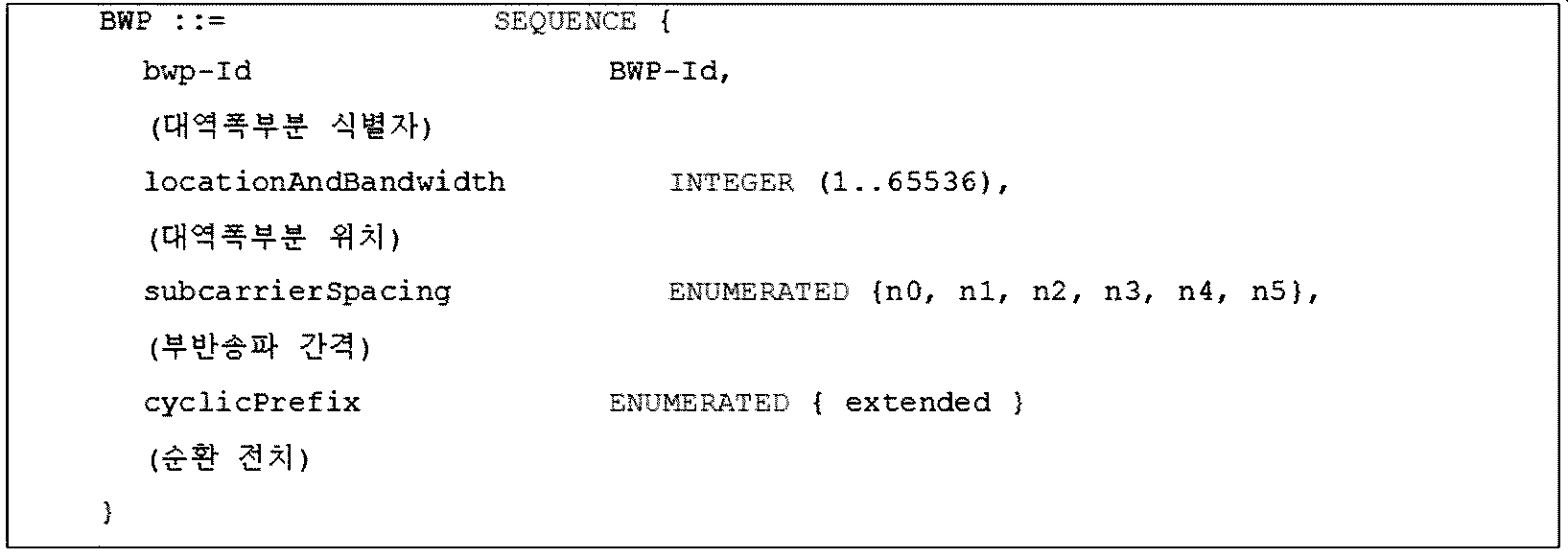
물론 상기 예시에 제한되는 것은 아니며, 상기 설정 정보 외에도 대역폭부분과 관련된 다양한 파라미터들이 단말에게 설정될 수 있다. 상기 정보들은 상위 계층 시그널링, 예를 들면, RRC(Radio Resource Control) 시그널링을 통해 기지국이 단말에게 전달할 수 있다. 설정된 하나 또는 복수 개의 대역폭부분들 중에서 적어도 하나의 대역폭부분이 활성화(Activation)될 수 있다. 설정된 대역폭부분에 대한 활성화 여부는 기지국으로부터 단말에게 RRC 시그널링을 통해 준-정적으로 전달되거나 DCI(Downlink Control Information)를 통해 동적으로 전달될 수 있다.
일부 실시예에 따르면, RRC(Radio Resource Control) 연결 전의 단말은 초기 접속을 위한 초기 대역폭부분(Initial BWP)을 MIB(Master Information Block)를 통해 기지국으로부터 설정 받을 수 있다. 보다 구체적으로 설명하면, 단말은 초기 접속 단계에서 MIB를 통해 초기 접속에 필요한 시스템 정보(Remaining System Information; RMSI 또는 System Information Block 1; SIB1에 해당할 수 있음)를 수신을 위한 PDCCH가 전송될 수 있는 제어영역(Control Resource Set, CORESET)과 탐색 공간(Search Space)에 대한 설정 정보를 수신할 수 있다. MIB로 설정되는 제어영역과 탐색공간은 각각 식별자(Identity, ID) 0으로 간주될 수 있다. 기지국은 단말에게 MIB를 통해 제어영역#0에 대한 주파수 할당 정보, 시간 할당 정보, 뉴머롤로지(Numerology) 등의 설정 정보를 통지할 수 있다. 또한 기지국은 단말에게 MIB를 통해 제어영역#0에 대한 모니터링 주기 및 occasion에 대한 설정정보, 즉 탐색공간#0에 대한 설정 정보를 통지할 수 있다. 단말은 MIB로부터 획득한 제어영역#0으로 설정된 주파수 영역을 초기 접속을 위한 초기 대역폭부분으로 간주할 수 있다. 이때, 초기 대역폭부분의 식별자(ID)는 0으로 간주될 수 있다.
상기 5G에서 지원하는 대역폭부분에 대한 설정은 다양한 목적으로 사용될 수 있다.
일부 실시 예에 따르면, 시스템 대역폭보다 단말이 지원하는 대역폭이 작을 경우에 상기 대역폭부분 설정을 통해 이를 지원할 수 있다. 예를 들면, 기지국은 대역폭부분의 주파수 위치(설정정보 2)를 단말에게 설정함으로써 시스템 대역폭 내의 특정 주파수 위치에서 단말이 데이터를 송수신할 수 있다.
또한 일부 실시예에 따르면, 서로 다른 뉴머롤로지를 지원하기 위한 목적으로 기지국이 단말에게 복수 개의 대역폭부분을 설정할 수 있다. 예를 들면, 어떤 단말에게 15kHz의 부반송파 간격과 30kHz의 부반송파 간격을 이용한 데이터 송수신을 모두 지원하기 위해서, 두 개의 대역폭 부분을 각각 15kHz와 30kHz의 부반송파 간격으로 설정할 수 있다. 서로 다른 대역폭 부분은 주파수 분할 다중화(Frequency Division Multiplexing)될 수 있고, 특정 부반송파 간격으로 데이터를 송수신하고자 할 경우, 해당 부반송파 간격으로 설정되어 있는 대역폭부분이 활성화 될 수 있다.
또한 일부 실시예에 따르면, 단말의 전력 소모 감소를 위한 목적으로 기지국이 단말에게 서로 다른 크기의 대역폭을 갖는 대역폭부분을 설정할 수 있다. 예를 들면, 단말이 매우 큰 대역폭, 예컨대 100MHz의 대역폭을 지원하고 해당 대역폭으로 항상 데이터를 송수신할 경우, 매우 큰 전력 소모가 발생될 수 있다. 특히 트래픽(Traffic)이 없는 상황에서 100MHz의 큰 대역폭으로 불필요한 하향링크 제어채널에 대한 모니터링을 수행하는 것은 전력 소모 관점에서 매우 비효율 적일 수 있다. 단말의 전력 소모를 줄이기 위한 목적으로, 기지국은 단말에게 상대적으로 작은 대역폭의 대역폭부분, 예를 들면, 20MHz의 대역폭부분을 설정할 수 있다. 트래픽이 없는 상황에서 단말은 20MHz 대역폭부분에서 모니터링 동작을 수행할 수 있고, 데이터가 발생하였을 경우 기지국의 지시에 따라 100MHz의 대역폭부분으로 데이터를 송수신할 수 있다.
상기 대역폭부분을 설정하는 방법에 있어서, RRC 연결(Connected) 전의 단말들은 초기 접속 단계에서 MIB(Master Information Block)을 통해 초기 대역폭부분(Initial Bandwidth Part)에 대한 설정 정보를 수신할 수 있다. 보다 구체적으로 설명하면, 단말은 PBCH(Physical Broadcast Channel)의 MIB로부터 SIB(System Information Block)를 스케쥴링하는 DCI(Downlink Control Information)가 전송될 수 있는 하향링크 제어채널을 위한 제어영역(Control Resource Set, CORESET)을 설정 받을 수 있다. MIB로 설정된 제어영역의 대역폭이 초기 대역폭부분으로 간주될 수 있으며, 설정된 초기 대역폭부분을 통해 단말은 SIB가 전송되는 PDSCH(Physical Downlink Shared Channel)를 수신할 수 있다. 초기 대역폭부분은 SIB을 수신하는 용도 외에도, 다른 시스템 정보(Other System Information, OSI), 페이징(Paging), 랜덤 엑세스(Random Access) 용으로 활용될 수도 있다.
단말에게 하나 이상의 대역폭파트가 설정되었을 경우, 기지국은 단말에게 DCI 내의 대역폭파트 지시자(Bandwidth Part Indicator) 필드를 이용하여, 대역폭파트에 대한 변경을 지시할 수 있다. 일 예로 도 3에서 단말의 현재 활성화된 대역폭파트가 대역폭파트#1(301)일 경우, 기지국은 단말에게 DCI 내의 대역폭파트 지시자로 대역폭파트#2(302)를 지시할 수 있고, 단말은 수신한 DCI 내의 대역폭파트 지시자로 지시된 대역폭파트#2(302)로 대역폭부분 변경을 수행할 수 있다.
전술한 바와 같이 DCI 기반 대역폭파트 변경은 PDSCH 또는 PUSCH를 스케쥴링하는 DCI에 의해 지시될 수 있기 때문에, 단말은 대역폭파트 변경 요청을 수신하였을 경우, 해당 DCI가 스케쥴링하는 PDSCH 또는 PUSCH를 변경된 대역폭파트에서 무리 없이 수신 또는 송신을 수행할 수 있어야 한다. 이를 위해, 표준에서는 대역폭파트 변경 시 요구되는 지연 시간(TBWP)에 대한 요구 사항을 규정하였으며, 예를 들어 하기와 같이 정의될 수 있다.
[표 2-1]

대역폭파트 변경 지연 시간에 대한 요구사항은 단말의 능력(Capability)에 따라 타입 1 또는 타입 2를 지원한다. 단말은 기지국에 지원 가능한 대역폭파트 지연 시간 타입을 보고할 수 있다.
전술한 대역폭파트 변경 지연시간에 대한 요구사항에 따라, 단말이 대역폭파트 변경 지시자를 포함하는 DCI를 슬롯 n에서 수신하였을 경우, 단말은 대역폭파트 변경 지시자가 가리키는 새로운 대역폭부분으로의 변경을 슬롯 n+TBWP보다 늦지 않은 시점에서 완료를 할 수 있고, 변경된 새로운 대역폭부분에서 해당 DCI가 스케쥴링하는 데이터채널에 대한 송수신을 수행할 수 있다. 기지국은 새로운 대역폭파트로 데이터채널을 스케쥴링하고자 할 경우, 단말의 대역폭파트 변경 지연시간(TBWP)을 고려하여, 데이터채널에 대한 시간 도메인 자원할당을 결정할 수 있다. 즉, 기지국은 새로운 대역폭파트로 데이터채널을 스케쥴링 할 때, 데이터채널에 대한 시간 도메인 자원할당을 결정하는 방법에 있어서, 대역폭파트 변경 지연시간 이 후로 해당 데이터채널을 스케쥴링할 수 있다. 이에 따라 단말은 대역폭 파트 변경을 지시하는 DCI가, 대역폭 파트 변경 지연 시간 (TBWP) 보다 작은 슬롯 오프셋 (K0 또는 K2) 값을 지시하는 것을 기대하지 않을 수 있다.
만약 단말이 대역폭 파트 변경을 지시하는 DCI(예를 들어 DCI 포맷 1_1 또는 0_1)을 수신하였다면, 단말은 해당 DCI를 포함하는 PDCCH를 수신한 슬롯의 세번째 심볼에서부터, 해당 DCI 내의 시간도메인 자원할당 지시자 필드로 지시된 슬롯 오프셋(K0 또는 K2) 값으로 지시된 슬롯의 시작 지점까지에 해당하는 시간 구간 동안 어떠한 송신 또는 수신도 수행하지 않을 수 있다. 예를 들어, 단말이 슬롯 n에서 대역폭 파트 변경을 지시하는 DCI를 수신하였고, 해당 DCI로 지시된 슬롯 오프셋 값이 K라고 한다면, 단말은 슬롯 n의 세번째 심볼에서부터 슬롯 n+K이전 심볼(즉 슬롯 n+K-1의 마지막 심볼)까지 어떠한 송신 또는 수신도 수행하지 않을 수 있다.
다음으로 5G에서의 SS(Synchronization Signal)/PBCH 블록에 대하여 설명하도록 한다.
SS/PBCH 블록이란 PSS(Primary SS), SSS(Secondary SS), PBCH로 구성된 물리계층 채널 블록을 의미할 수 있다. 구체적으로는 하기와 같다.
- PSS: 하향링크 시간/주파수 동기의 기준이 되는 신호로 셀 ID 의 일부 정보를 제공한다.
- SSS: 하향링크 시간/주파수 동기의 기준이 되고, PSS 가 제공하지 않은 나머지 셀 ID 정보를 제공한다. 추가적으로 PBCH 의 복조를 위한 기준신호(Reference Signal) 역할을 할 수 있다.
- PBCH: 단말의 데이터채널 및 제어채널 송수신에 필요한 필수 시스템 정보를 제공한다. 필수 시스템 정보는 제어채널의 무선자원 매핑 정보를 나타내는 탐색공간 관련 제어정보, 시스템 정보를 전송하는 별도의 데이터 채널에 대한 스케쥴링 제어정보 등을 포함할 수 있다.
- SS/PBCH 블록: SS/PBCH 블록은 PSS, SSS, PBCH의 조합으로 이뤄진다. SS/PBCH 블록은 5ms 시간 내에서 하나 또는 복수 개가 전송될 수 있고, 전송되는 각각의 SS/PBCH 블록은 인덱스로 구별될 수 있다.
단말은 초기 접속 단계에서 PSS 및 SSS를 검출할 수 있고, PBCH를 디코딩할 수 있다. PBCH로부터 MIB를 획득할 수 있고 이로부터 제어영역(Control Resource Set; CORESET)#0 (제어영역 인덱스가 0인 제어영역에 해당할 수 있음)을 설정 받을 수 있다. 단말은 선택한 SS/PBCH 블록과 제어영역#0에서 전송되는 DMRS(Demodulation Reference signal)이 QCL(Quasi Co Location)되어 있다고 가정하고 제어영역#0에 대한 모니터링을 수행할 수 있다. 단말은 제어영역#0에서 전송된 하향링크 제어정보로 시스템 정보를 수신할 수 있다. 단말은 수신한 시스템 정보로부터 초기 접속에 필요한 RACH(Random Access Channel) 관련 설정 정보를 획득할 수 있다. 단말은 선택한 SS/PBCH 인덱스를 고려하여 PRACH(Physical RACH)를 기지국으로 전송할 수 있고, PRACH를 수신한 기지국은 단말이 선택한 SS/PBCH 블록 인덱스에 대한 정보를 획득할 수 있다. 기지국은 단말이 각각의 SS/PBCH 블록들 중에서 어떤 블록을 선택하였고 이와 연관되어 있는 제어영역#0을 모니터링하는 사실을 알 수 있다.
다음으로 5G 시스템에서의 하향링크 제어 정보(Downlink Control Information, DCI)에 대해 구체적으로 설명한다.
5G 시스템에서 상향링크 데이터(또는 물리 상향링크 데이터 채널(Physical Uplink Shared Channel, PUSCH)) 또는 하향링크 데이터(또는 물리 하향링크 데이터 채널(Physical Downlink Shared Channel, PDSCH))에 대한 스케줄링 정보는 DCI를 통해 기지국으로부터 단말에게 전달된다. 단말은 PUSCH 또는 PDSCH에 대하여 대비책(Fallback)용 DCI 포맷과 비대비책(Non-fallback)용 DCI 포맷을 모니터링(Monitoring)할 수 있다. 대비책 DCI 포맷은 기지국과 단말 사이에서 선정의된 고정된 필드로 구성될 수 있고, 비대비책용 DCI 포맷은 설정 가능한 필드를 포함할 수 있다.
DCI는 채널코딩 및 변조 과정을 거쳐 물리 하향링크 제어 채널인 PDCCH(Physical Downlink Control Channel)을 통해 전송될 수 있다. DCI 메시지 페이로드(payload)에는 CRC(Cyclic Redundancy Check)가 부착되며 CRC는 단말의 신원에 해당하는 RNTI(Radio Network Temporary Identifier)로 스크램블링(scrambling) 될 수 있다. DCI 메시지의 목적, 예를 들어 단말-특정(UE-specific)의 데이터 전송, 전력 제어 명령 또는 랜덤 엑세스 응답 등에 따라 서로 다른 RNTI들이 사용될 수 있다. 즉, RNTI는 명시적으로 전송되지 않고 CRC 계산과정에 포함되어 전송된다. PDCCH 상으로 전송되는 DCI 메시지를 수신하면 단말은 할당 받은 RNTI를 사용하여 CRC를 확인하여 CRC 확인 결과가 맞으면 단말은 해당 메시지가 단말에게 전송된 것임을 알 수 있다.
예를 들면, 시스템 정보(System Information, SI)에 대한 PDSCH를 스케줄링하는 DCI는 SI-RNTI로 스크램블링될 수 있다. RAR(Random Access Response) 메시지에 대한 PDSCH를 스케줄링하는 DCI는 RA-RNTI로 스크램블링 될 수 있다. 페이징(Paging) 메시지에 대한 PDSCH를 스케줄링하는 DCI는 P-RNTI로 스크램블링 될 수 있다. SFI(Slot Format Indicator)를 통지하는 DCI는 SFI-RNTI로 스크램블링 될 수 있다. TPC(Transmit Power Control)를 통지하는 DCI는 TPC-RNTI로 스크램블링 될 수 있다. 단말-특정의 PDSCH 또는 PUSCH를 스케줄링하는 DCI는 C-RNTI(Cell RNTI)로 스크램블링 될 수 있다.
DCI 포맷 0_0은 PUSCH를 스케줄링하는 대비책 DCI로 사용될 수 있고, 이 때 CRC는 C-RNTI로 스크램블링될 수 있다. C-RNTI로 CRC가 스크램블링 된 DCI 포맷 0_0은 예컨대 하기의 정보들을 포함할 수 있다.

DCI 포맷 0_1은 PUSCH를 스케줄링하는 비대비책 DCI로 사용될 수 있고, 이 때 CRC는 C-RNTI로 스크램블링될 수 있다. C-RNTI로 CRC가 스크램블링 된 DCI 포맷 0_1은 예컨대 하기의 정보들을 포함할 수 있다.


DCI 포맷 1_0은 PDSCH를 스케줄링하는 대비책 DCI로 사용될 수 있고, 이 때 CRC는 C-RNTI로 스크램블링될 수 있다. C-RNTI로 CRC가 스크램블링 된 DCI 포맷 1_0은 예컨대 하기의 정보들을 포함할 수 있다.

DCI 포맷 1_1은 PDSCH를 스케줄링하는 비대비책 DCI로 사용될 수 있고, 이 때 CRC는 C-RNTI로 스크램블링될 수 있다. C-RNTI로 CRC가 스크램블링 된 DCI 포맷 1_1은 예컨대 하기의 정보들을 포함할 수 있다.

하기에서는 5G 통신 시스템에서 데이터 채널에 대한 시간 도메인 자원할당 방법에 대해 설명하도록 한다.
기지국은 단말에게 하향링크 데이터채널(Physical Downlink Shared Channel; PDSCH) 및 상향링크 데이터채널(Physical Uplink Shared Channel; PUSCH)에 대한 시간 도메인 자원할당 정보에 대한 테이블(Table)을 상위 계층 시그널링 (예를 들어 RRC 시그널링)으로 설정할 수 있다. PDSCH에 대해서는 최대 maxNrofDL-Allocations=16 개의 엔트리(Entry)로 구성된 테이블을 설정할 수 있고, PUSCH에 대해서는 최대 maxNrofUL-Allocations=16 개의 엔트리(Entry)로 구성된 테이블을 설정할 수 있다. 시간 도메인 자원할당 정보에는 예를 들어 PDCCH-to-PDSCH 슬롯 타이밍 (PDCCH를 수신한 시점과 수신한 PDCCH가 스케쥴링하는 PDSCH가 전송되는 시점 사이의 슬롯 단위의 시간 간격에 해당함, K0로 표기함) 또는 PDCCH-to-PUSCH 슬롯 타이밍 (PDCCH를 수신한 시점과 수신한 PDCCH가 스케쥴링하는 PUSCH가 전송되는 시점 사이의 슬롯 단위의 시간 간격에 해당함, K2로 표기함), 슬롯 내에서 PDSCH 또는 PUSCH가 스케쥴링된 시작 심볼의 위치 및 길이에 대한 정보, PDSCH 또는 PUSCH의 매핑 타입 등이 포함될 수 있다. 예를 들어 하기 표와 같은 정보들이 기지국으로부터 단말로 통지될 수 있다.


기지국은 상기 시간 도메인 자원할당 정보에 대한 테이블의 엔트리 중 하나를 단말에게 L1 시그널링(예를 들어 DCI)를 통해 단말에게 통지할 수 있다 (예를 들어 DCI 내의 '시간 도메인 자원할당' 필드로 지시할 수 있음). 단말은 기지국으로부터 수신한 DCI에 기반하여 PDSCH 또는 PUSCH에 대한 시간 도메인 자원할당 정보를 획득할 수 있다.
하기에서는 5G 통신 시스템에서의 하향링크 제어채널에 대하여 도면을 참조하여 보다 구체적으로 설명하고자 한다.
도 4는 5G 무선통신 시스템에서 하향링크 제어채널이 전송되는 제어영역(Control Resource Set, CORESET)에 대한 일 예를 도시한 도면이다. 도 4는 주파수 축으로 단말의 대역폭부분(UE bandwidth part)(410), 시간축으로 1 슬롯(420) 내에 2개의 제어영역(제어영역#1(401), 제어영역#2(402))이 설정되어 있는 일 예를 도시한다. 제어영역(401, 402)는 주파수 축으로 전체 단말 대역폭부분(410) 내에서 특정 주파수 자원(403)에 설정될 수 있다. 시간 축으로는 하나 또는 복수 개의 OFDM 심볼로 설정될 수 있고 이를 제어영역 길이(Control Resource Set Duration, 404)으로 정의할 수 있다. 도 4의 도시된 예를 참조하면, 제어영역#1(401)은 2 심볼의 제어영역 길이로 설정되어 있고, 제어영역#2(402)는 1 심볼의 제어영역 길이로 설정되어 있다.
전술한 5G에서의 제어영역은 기지국이 단말에게 상위 계층 시그널링(예컨대 시스템 정보(System Information), MIB(Master Information Block), RRC(Radio Resource Control) 시그널링)을 통해 설정될 수 있다. 단말에게 제어영역을 설정한다는 것은 제어영역 식별자(Identity), 제어영역의 주파수 위치, 제어영역의 심볼 길이 등의 정보를 제공하는 것을 의미한다. 예를 들면, 하기의 정보들을 포함할 수 있다.

표 9에서 tci-StatesPDCCH (간단히 TCI(Transmission Configuration Indication) state로 명명함) 설정 정보는, 대응되는 제어영역에서 전송되는 DMRS와 QCL(Quasi Co Located) 관계에 있는 하나 또는 복수 개의 SS(Synchronization Signal)/PBCH(Physical Broadcast Channel) 블록(Block) 인덱스 또는 CSI-RS(Channel State Information Reference Signal) 인덱스의 정보를 포함할 수 있다.
도 5는 5G에서 사용될 수 있는 하향링크 제어채널을 구성하는 시간 및 주파수 자원의 기본단위의 일 예를 보여주는 도면이다. 도 5에 따르면 제어채널을 구성하는 시간 및 주파수 자원의 기본 단위를 REG(Resource Element Group, 503)라 할 수 있으며, REG(503)는 시간 축으로 1 OFDM 심볼(501), 주파수 축으로 1 PRB(Physical Resource Block, 502), 즉, 12개 서브캐리어(Subcarrier)로 정의될 수 있다. 기지국은 REG(503)를 연접하여 하향링크 제어채널 할당 단위를 구성할 수 있다.
도 5에 도시된 바와 같이 5G에서 하향링크 제어채널이 할당되는 기본 단위를 CCE(Control Channel Element, 504)라고 할 경우, 1 CCE(504)는 복수의 REG(503)로 구성될 수 있다. 도 5에 도시된 REG(503)를 예를 들어 설명하면, REG(503)는 12개의 RE로 구성될 수 있고, 1 CCE(504)가 6개의 REG(503)로 구성된다면 1 CCE(504)는 72개의 RE로 구성될 수 있다. 하향링크 제어영역이 설정되면 해당 영역은 복수의 CCE(504)로 구성될 수 있으며, 특정 하향링크 제어채널은 제어영역 내의 집성 레벨(Aggregation Level; AL)에 따라 하나 또는 복수의 CCE(504)로 매핑 되어 전송될 수 있다. 제어영역내의 CCE(504)들은 번호로 구분되며 이 때 CCE(504)들의 번호는 논리적인 매핑 방식에 따라 부여될 수 있다.
도 5에 도시된 하향링크 제어채널의 기본 단위, 즉 REG(503)에는 DCI가 매핑되는 RE들과 이를 디코딩하기 위한 레퍼런스 신호인 DMRS(505)가 매핑되는 영역이 모두 포함될 수 있다. 도 5에서와 같이 1 REG(503) 내에 3개의 DMRS(505)가 전송될 수 있다. PDCCH를 전송하는데 필요한 CCE의 개수는 집성 레벨(Aggregation Level, AL)에 따라 1, 2, 4, 8, 16개가 될 수 있으며, 서로 다른 CCE 개수는 하향링크 제어채널의 링크 적응(link adaptation)을 구현하기 위해 사용될 수 있다. 예컨대 AL=L일 경우, 하나의 하향링크 제어채널이 L 개의 CCE를 통해 전송될 수 있다. 단말은 하향링크 제어채널에 대한 정보를 모르는 상태에서 신호를 검출해야 하는데, 블라인드 디코딩을 위해 CCE들의 집합을 나타내는 탐색공간(search space)를 정의하였다. 탐색공간은 주어진 집성 레벨 상에서 단말이 디코딩을 시도해야 하는 CCE들로 이루어진 하향링크 제어채널 후보군(Candidate)들의 집합이며, 1, 2, 4, 8, 16 개의 CCE로 하나의 묶음을 만드는 여러 가지 집성 레벨이 있으므로 단말은 복수개의 탐색공간을 가질 수 있다. 탐색공간 세트(Set)는 설정된 모든 집성 레벨에서의 탐색공간들의 집합으로 정의될 수 있다.
탐색공간은 공통(Common) 탐색공간과 단말-특정(UE-specific) 탐색공간으로 분류될 수 있다. 일정 그룹의 단말들 또는 모든 단말들이 시스템정보에 대한 동적인 스케줄링이나 페이징 메시지와 같은 셀 공통의 제어정보를 수신하기 위해 PDCCH의 공통 탐색 공간을 조사할 수 있다. 예를 들어 셀의 사업자 정보 등을 포함하는 SIB의 전송을 위한 PDSCH 스케줄링 할당 정보는 PDCCH의 공통 탐색 공간을 조사하여 수신할 수 있다. 공통 탐색공간의 경우, 일정 그룹의 단말들 또는 모든 단말들이 PDCCH를 수신해야 하므로 기 약속된 CCE의 집합으로써 정의될 수 있다. 단말-특정적인 PDSCH 또는 PUSCH에 대한 스케쥴링 할당 정보는 PDCCH의 단말-특정 탐색공간을 조사함으로써 수신될 수 있다. 단말-특정 탐색공간은 단말의 신원(Identity) 및 다양한 시스템 파라미터의 함수로 단말-특정적으로 정의될 수 있다.
5G에서는 PDCCH에 대한 탐색공간에 대한 파라미터는 상위 계층 시그널링(예컨대, SIB, MIB, RRC 시그널링)으로 기지국으로부터 단말로 설정될 수 있다. 예를 들면, 기지국은 각 집성 레벨 L에서의 PDCCH 후보군 수, 탐색공간에 대한 모니터링 주기, 탐색공간에 대한 슬롯 내 심볼 단위의 모니터링 occasion, 탐색공간 타입(공통 탐색공간 또는 단말-특정 탐색공간), 해당 탐색공간에서 모니터링 하고자 하는 DCI 포맷과 RNTI의 조합, 탐색공간을 모니터링 하고자 하는 제어영역 인덱스 등을 단말에게 설정할 수 있다. 예를 들면, 하기의 정보들을 포함할 수 있다.

설정 정보에 따라 기지국은 단말에게 하나 또는 복수 개의 탐색공간 세트를 설정할 수 있다. 일부 실시예에 따르면, 기지국은 단말에게 탐색공간 세트 1과 탐색공간 세트 2를 설정할 수 있고, 탐색공간 세트 1에서 X-RNTI로 스크램블링된 DCI 포맷 A를 공통 탐색공간에서 모니터링 하도록 설정할 수 있고, 탐색공간 세트 2에서 Y-RNTI로 스크램블링된 DCI 포맷 B를 단말-특정 탐색공간에서 모니터링 하도록 설정할 수 있다.
설정 정보에 따르면, 공통 탐색공간 또는 단말-특정 탐색공간에 하나 또는 복수 개의 탐색공간 세트가 존재할 수 있다. 예를 들어 탐색공간 세트#1과 탐색공간 세트#2가 공통 탐색공간으로 설정될 수 있고, 탐색공간 세트#3과 탐색공간 세트#4가 단말-특정 탐색공간으로 설정될 수 있다.
공통 탐색공간에서는 하기의 DCI 포맷과 RNTI의 조합이 모니터링 될 수 있다. 물론 하기 예시에 제한되지 않는다.
- DCI format 0_0/1_0 with CRC scrambled by C-RNTI, CS-RNTI, SP-CSI-RNTI, RA-RNTI, TC-RNTI, P-RNTI, SI-RNTI
- DCI format 2_0 with CRC scrambled by SFI-RNTI
- DCI format 2_1 with CRC scrambled by INT-RNTI
- DCI format 2_2 with CRC scrambled by TPC-PUSCH-RNTI, TPC-PUCCH-RNTI
- DCI format 2_3 with CRC scrambled by TPC-SRS-RNTI
단말-특정 탐색공간에서는 하기의 DCI 포맷과 RNTI의 조합이 모니터링 될 수 있다. 물론 하기 예시에 제한되지 않는다.
- DCI format 0_0/1_0 with CRC scrambled by C-RNTI, CS-RNTI, TC-RNTI
- DCI format 1_0/1_1 with CRC scrambled by C-RNTI, CS-RNTI, TC-RNTI
명시되어 있는 RNTI들은 하기의 정의 및 용도를 따를 수 있다.
C-RNTI (Cell RNTI): 단말-특정 PDSCH 스케쥴링 용도
TC-RNTI (Temporary Cell RNTI): 단말-특정 PDSCH 스케쥴링 용도
CS-RNTI(Configured Scheduling RNTI): 준-정적으로 설정된 단말-특정 PDSCH 스케쥴링 용도
RA-RNTI (Random Access RNTI): 랜덤 엑세스 단계에서 PDSCH 스케쥴링 용도
P-RNTI (Paging RNTI): 페이징이 전송되는 PDSCH 스케쥴링 용도
SI-RNTI (System Information RNTI): 시스템 정보가 전송되는 PDSCH 스케쥴링 용도
INT-RNTI (Interruption RNTI): PDSCH에 대한 pucturing 여부를 알려주기 위한 용도
TPC-PUSCH-RNTI (Transmit Power Control for PUSCH RNTI): PUSCH에 대한 전력 조절 명령 지시 용도
TPC-PUCCH-RNTI (Transmit Power Control for PUCCH RNTI): PUCCH에 대한 전력 조절 명령 지시 용도
TPC-SRS-RNTI (Transmit Power Control for SRS RNTI): SRS에 대한 전력 조절 명령 지시 용도
전술한 명시된 DCI 포맷들은 하기의 정의를 따를 수 있다.

5G에서 제어영역 p, 탐색공간 세트 s에서 집성 레벨 L의 탐색공간은 하기의 수학식과 같이 표현될 수 있다.
[수학식 1]

- L: 집성 레벨
- nCI: 캐리어(Carrier) 인덱스
- NCCE,p: 제어영역 p 내에 존재하는 총 CCE 개수
- nμ
s,f: 슬롯 인덱스
- M(L)
p,s,max: 집성 레벨 L의 PDCCH 후보군 수
- msnCI = 0, ..., M(L)
p,s,max -1: 집성 레벨 L의 PDCCH 후보군 인덱스
- i = 0, ..., L-1
- 

- nRNTI : 단말 식별자
Y_(p,nμ
s,f) 값은 공통 탐색공간의 경우 0에 해당할 수 있다.
Y_(p,nμ
s,f) 값은 단말-특정 탐색공간의 경우, 단말의 신원(C-RNTI 또는 기지국이 단말에게 설정해준 ID)과 시간 인덱스에 따라 변하는 값에 해당할 수 있다.
5G에서는 복수 개의 탐색공간 세트가 서로 다른 파라미터들(예컨대, 표 10의 파라미터들)로 설정될 수 있음에 따라, 매 시점에서 단말이 모니터링하는 탐색공간 세트의 집합이 달라질 수 있다. 예를 들면, 탐색공간 세트#1이 X-슬롯 주기로 설정되어 있고, 탐색공간 세트#2가 Y-슬롯 주기로 설정되어 있고 X와 Y가 다를 경우, 단말은 특정 슬롯에서는 탐색공간 세트#1과 탐색공간 세트#2를 모두 모니터링 할 수 있고, 특정 슬롯에서는 탐색공간 세트#1과 탐색공간 세트#2 중 하나를 모니터링 할 수 있다.
복수 개의 탐색공간 세트가 단말에게 설정되었을 경우, 단말이 모니터링해야 하는 탐색공간 세트를 결정하는 방법에 있어서 하기의 조건들이 고려될 수 있다.
[조건 1: 최대 PDCCH 후보군 수 제한]
슬롯 당 모니터링 할 수 있는 PDCCH 후보군의 수는 Mμ를 넘지 않는다. Mμ는 서브캐리어 간격 15·2μ kHz으로 설정된 셀에서의 슬롯 당 최대 PDCCH 후보군 수로 정의될 수 있으며, 하기 표로 정의될 수 있다.

[조건 2: 최대 CCE 수 제한]
슬롯 당 전체 탐색공간(여기서 전체 탐색공간이란 복수 개의 탐색공간 세트의 union 영역에 해당하는 전체 CCE 집합을 의미)을 구성하는 CCE의 개수가 Cμ를 넘지 않는다. Cμ는 서브캐리어 간격 15·2μ kHz으로 설정된 셀에서의 슬롯 당 최대 CCE의 수로 정의될 수 있으며, 하기 표로 정의될 수 있다.

설명의 편의를 위해, 특정 시점에서 상기 조건 1, 2를 모두 만족시키는 상황을 "조건 A"로 정의하도록 한다. 따라서 조건 A를 만족시키지 않는 것은 상기 조건 1, 2 중에서 적어도 하나의 조건을 만족시키지 않는 것을 의미할 수 있다.
기지국의 탐색공간 세트들의 설정에 따라 특정 시점에서 조건 A를 만족하지 않는 경우가 발생할 수 있다. 특정 시점에서 조건 A를 만족하지 않을 경우, 단말은 해당 시점에서 조건 A를 만족하도록 설정된 탐색공간 세트들 중에서 일부만을 선택하여 모니터링 할 수 있고, 기지국은 선택된 탐색공간 세트로 PDCCH를 전송할 수 있다.
전체 설정된 탐색공간 세트 중에서 일부 탐색공간을 선택하는 방법으로 하기의 방법을 따를 수 있다.
[방법 1]
특정 시점(슬롯)에서 PDCCH에 대한 조건 A를 만족시키지 못할 경우,
단말은(또는 기지국은) 해당 시점에 존재하는 탐색공간 세트들 중에서 탐색 공간 타입이 공통 탐색공간으로 설정되어 있는 탐색공간 세트를 단말-특정 탐색공간으로 설정된 탐색공간 세트보다 우선적으로 선택할 수 있다.
공통 탐색공간으로 설정되어 있는 탐색공간 세트들이 모두 선택되었을 경우(즉, 공통 탐색공간으로 설정되어 있는 모든 탐색공간을 선택한 후에도 조건 A를 만족할 경우), 단말은(또는 기지국은) 단말-특정 탐색공간으로 설정되어 있는 탐색공간 세트들을 선택할 수 있다. 이 때, 단말-특정 탐색공간으로 설정되어 있는 탐색공간 세트가 복수 개일 경우, 탐색공간 세트 인덱스(Index)가 낮은 탐색공간 세트가 더 높은 우선 순위를 가질 수 있다. 우선 순위를 고려하여 단말-특정 탐색공간 세트들을 조건 A가 만족되는 범위 내에서 선택할 수 있다.
도 6은 DRX(Discontinuous Reception)를 설명하기 위한 도면이다.
DRX(Discontinuous Reception)는 서비스를 이용 중인 단말이 기지국과 단말 간에 무선링크가 설정되어 있는 RRC 연결(RRC Connected) 상태에서 데이터를 비연속적으로 수신하는 동작이다. DRX가 적용되면, 단말은 특정 시점에서 수신기를 온(on)하여 제어 채널을 모니터링하고, 일정 기간 동안 수신되는 데이터가 없으면 수신기를 오프(off)하여 단말의 전력 소모를 줄일 수 있다. DRX 동작은 다양한 파라미터 및 타이머에 기초하여 MAC 계층 장치에 의해 제어될 수 있다.
도 6을 참조하면, Active time(605)은 단말이 DRX 주기마다 깨어나서 PDCCH를 모니터링 하는 시간이다. Active time(605)는 다음과 같이 정의될 수 있다.
- drx-onDurationTimer or drx-InactivityTimer or drx-RetransmissionTimerDL or drx-RetransmissionTimerUL or ra-ContentionResolutionTimer is running; 또는
- a Scheduling Request is sent on PUCCH and is pending; 또는
- a PDCCH indicating a new transmission addressed to the C-RNTI of the MAC entity has not been received after successful reception of a Random Access Response for the Random Access Preamble not selected by the MAC entity among the contention-based Random Access Preamble
drx-onDurationTimer, drx-InactivityTimer, drx-RetransmissionTimerDL, drx-RetransmissionTimerUL, ra-ContentionResolutionTimer 등은 기지국에 의해서 그 값이 설정되는 타이머들이며, 소정의 조건이 만족된 상황에서 단말이 PDCCH를 모니터링 하도록 설정하는 기능을 가지고 있다.
drx-onDurationTimer(615)는 DRX cycle에서 단말이 깨어있는 최소 시간을 설정하기 위한 파라미터이다. drx-InactivityTimer(620)는 새로운 상향링크 전송 또는 하향링크 전송을 지시하는 PDCCH를 수신(630)하는 경우, 단말이 추가적으로 깨어있는 시간을 설정하기 위한 파라미터이다. drx-RetransmissionTimerDL는 하향링크 HARQ 절차에서 하향링크 재전송을 수신하기 위하여 단말이 깨어있는 최대 시간을 설정하기 위한 파라미터이다. drx-RetransmissionTimerUL는 상향링크 HARQ 절차에서 상향링크 재전송 승인(grant)을 수신하기 위하여 단말이 깨어있는 최대 시간을 설정하기 위한 파라미터이다. drx-onDurationTimer, drx-InactivityTimer, drx-RetransmissionTimerDL 및 drx-RetransmissionTimerUL는 예를 들어, 시간, 서브프레임(subframe) 개수, 슬롯 개수 등으로 설정될 수 있다. ra-ContentionResolutionTimer는 랜덤 액세스 절차에서 PDCCH를 모니터링 위한 파라미터이다.
inActive time(610)은 DRX 동작 중 PDCCH를 모니터링하지 않도록 설정되는 시간 또는/혹은 PDCCH를 수신하지 않도록 설정되는 시간으로, DRX 동작을 수행하는 전체 시간에서 Active time(605)를 제외한 나머지 시간이 inActive time(610)이 될 수 있다. 단말은 Active time(605) 동안 PDCCH를 모니터링하지 않으면, 슬립(sleep) 또는 inActive 상태로 진입하여 전력 소모를 줄일 수 있다.
DRX cycle은 단말이 깨어나서 PDCCH를 모니터링 하는 주기를 의미한다. 즉, 단말이 PDCCH를 모니터링 한 후, 다음 PDCCH를 모니터링 하기까지의 시간 간격 또는 온 듀레이션(on duration)의 발생 주기를 의미한다. DRX cycle은 short DRX cycle 과 long DRX cycle 2 종류가 있다. Short DRX cycle은 선택적(option)으로 적용될 수 있다.
Long DRX cycle(625)은 단말에 설정되는 두 가지 DRX cycle 중 긴 cycle이다. 단말은 Long DRX로 동작하는 동안에는 drx-onDurationTimer(615)의 시작점(예를 들어, 시작 심볼)에서 Long DRX cycle(625) 만큼 경과한 시점에 다시 drx-onDurationTimer(615)를 시작한다. Long DRX cycle(625)로 동작하는 경우, 단말은 아래 수학식 2를 만족하는 서브프레임에서 drx-SlotOffset 이후 슬롯에서 drx-onDurationTimer(615)를 시작할 수 있다. 여기서, drx-SlotOffset은 drx-onDurationTimer(615)를 시작하기 전 지연(delay)을 의미한다. drx-SlotOffset은 예를 들어, 시간, 슬롯 개수 등으로 설정될 수 있다.
[수학식 2]
[(SFN X 10) + subframe number] modulo (drx-LongCycle) = drx-StartOffset
이때, drx-LongCycleStartOffset은 Long DRX cycle(625)과 drx-StartOffset은 Long DRX cycle(625)을 시작할 서브프레임을 정의하는데 사용될 수 있다. drx-LongCycleStartOffset은 예를 들어, 시간, 서브프레임 개수, 슬롯 개수 등으로 설정될 수 있다.
하기에서는 5G 통신 시스템에서의 캐리어 집성 (Carrier Aggregation) 및 스케쥴링 방법에 대하여 구체적으로 설명하도록 한다.
단말은 기지국으로부터 다수의 셀 (Cell 또는 CC(Component Carrier))를 설정 받을 수 있고, 단말에 설정된 셀들에 대한 크로스-캐리어 스케쥴링 여부를 설정 받을 수 있다. 만약 특정 셀(셀 A, 스케쥴링되는 셀(Scheduled Cell))이 크로스-캐리어 스케쥴링으로 설정되었다면, 셀 A에 대한 PDCCH 모니터링은 셀 A에서 수행되지 않고, 크로스-캐리어 스케쥴링으로 지시된 다른 셀 (셀 B, 스케쥴링하는 셀(Scheduling Cell))에서 수행될 수 있다. 이 때 스케쥴링되는 셀(셀 A)과 스케쥴링하는 셀(셀 B)은 서로 다른 뉴머롤로지(Numerology)로 설정될 수 있다. 여기서 뉴머롤로지는 부반송파 간격, Cyclic Prefix 등이 포함될 수 있다. 셀 A와 셀 B의 뉴머롤로지가 다를 경우, 셀 B의 PDCCH가 셀 A의 PDSCH를 스케쥴링할 때, PDCCH와 PDSCH 사이에 하기와 같은 최소 스케쥴링 오프셋이 추가로 고려될 수 있다.
[크로스-캐리어 스케쥴링 방법]
■ 셀 B의 부반송파 간격(μB)이 셀 A의 부반송파 간격(μA) 보다 작을 경우, 셀 B에서 수신한 PDCCH의 마지막 심볼에서부터 X 심볼 이후에 해당하는 다음 PDSCH 슬롯에서부터 PDSCH가 스케쥴링 될 수 있다. 여기서 X는 μB에 따라 다를 수 있으며, μB=15kHz 일 때 X=4 심볼, μB=30kHz 일 때 X=4 심볼, μB=60kHz 일 때, X=8 심볼로 정의될 수 있다.
■ 셀 B의 부반송파 간격(μB)이 셀 A의 부반송파 간격(μA) 보다 클 경우, 셀 B에서 수신한 PDCCH의 마지막 심볼에서부터 X 심볼 이후에 해당하는 시점에서부터 PDSCH가 스케쥴링 될 수 있다. 여기서 X는 μB에 따라 다를 수 있으며, μB=30kHz 일 때 X=4 심볼, μB=60kHz 일 때 X=8 심볼, μB=120kHz 일 때, X=12 심볼로 정의될 수 있다.
이하 본 개시의 실시 예를 첨부한 도면과 함께 상세히 설명한다. 이하에서는 5G 시스템을 일례로서 본 개시의 실시예를 설명하지만, 유사한 기술적 배경 또는 채널형태를 갖는 여타의 통신시스템에도 본 개시의 실시예가 적용될 수 있다. 예를 들어 LTE 또는 LTE-A 이동통신 및 5G 이후에 개발되는 이동통신 기술이 이에 포함될 수 있을 것이다. 따라서, 본 개시의 실시예는 본 기술 분야의 통상의 기술자의 판단으로써 본 개시의 범위를 크게 벗어나지 아니하는 범위에서 일부 변형을 통해 다른 통신시스템에도 적용될 수 있다.
또한, 본 개시를 설명함에 있어서 관련된 기능 또는 구성에 대한 구체적인 설명이 본 개시의 요지를 불필요하게 흐릴 수 있다고 판단된 경우 그 상세한 설명은 생략한다. 그리고 후술되는 용어들은 본 개시에서의 기능을 고려하여 정의된 용어들로서 이는 사용자, 운용자의 의도 또는 관례 등에 따라 달라질 수 있다. 그러므로 그 정의는 본 명세서 전반에 걸친 내용을 토대로 내려져야 할 것이다.
이하 본 개시를 설명함에 있어서, 상위 계층 시그널링이라 함은 하기의 시그널링 중에서 적어도 하나 또는 하나 이상의 조합에 해당하는 시그널링 일 수 있다.
- MIB (Master Information Block)
- SIB (System Information Block) 또는 SIB X (X=1, 2, ...)
- RRC (Radio Resource Control)
- MAC (Medium Access Control) CE (Control Element)
또한, L1 시그널링이라 함은 하기의 물리 계층 채널 또는 시그널링을 이용한 시그널링 방법 중에서 적어도 하나 또는 하나 이상의 조합에 해당하는 시그널링 일 수 있다.
- PDCCH (Physical Downlink Control Channel)
- DCI (Downlink Control Information)
- 단말-특정 (UE-specific) DCI
- 그룹 공통 (Group common) DCI
- 공통 (Common) DCI
- 스케쥴링 DCI (예를 들어 하향링크 또는 상향링크 데이터를 스케쥴링하는 목적으로 사용되는 DCI)
- 비스케쥴링 DCI (예를 들어 하향링크 또는 상향링크 데이터를 스케쥴링하는 목적이 아닌 DCI)
- PUCCH (Physical Uplink Control Channel)
- UCI (Uplink Control Information)
이하 본 개시를 설명함에 있어서, 하기의 함수를 정의하여 사용한다.
- min(A,B): A와 B 중에서 작은 값을 출력하는 함수
- max(A,B): A와 B중에서 큰 값을 출력하는 함수
- ceil(X): X보다 큰 정수들 중에서 가장 작은 정수를 출력하는 함수
- floor(X): X보다 작은 정수들 중에 가장 큰 정수를 출력하는 함수
이하 도면을 참조하여 본 발명의 다양한 실시 예에 따른 차세대 이동통신 시스템(5G 또는 NR 시스템)에서 데이터 채널에 대한 시간 도메인 자원할당 방법에 대해 설명하도록 한다.
기지국은 단말에게 PDSCH(Physical Downlink Shared CHannel) 및 PUSCH(Physical Uplink Shared CHannel)에 대한 시간 도메인 자원할당 정보에 대한 테이블(Table)을 상위 계층 시그널링(예를 들어 SIB, RRC 시그널링)으로 설정할 수 있다. PDSCH에 대해서는 최대 maxNrofDL-Allocations=16 개의 엔트리(Entry)로 구성된 테이블을 설정할 수 있고, PUSCH에 대해서는 최대 maxNrofUL-Allocations=16 개의 엔트리(Entry)로 구성된 테이블을 설정할 수 있다. 시간 도메인 자원할당 정보에는 예를 들어 PDCCH-to-PDSCH 슬롯 타이밍 (PDCCH를 수신한 시점과 수신한 PDCCH(Physical Downlink Control CHannel)가 스케쥴링하는 PDSCH가 전송되는 시점 사이의 슬롯 단위의 시간 간격에 해당함, K0로 표기함) 또는 PDCCH-to-PUSCH 슬롯 타이밍 (PDCCH를 수신한 시점과 수신한 PDCCH가 스케쥴링하는 PUSCH가 전송되는 시점 사이의 슬롯 단위의 시간 간격에 해당함, K2로 표기함), 슬롯 내에서 PDSCH 또는 PUSCH가 스케쥴링된 시작 심볼의 위치 및 길이에 대한 정보, PDSCH 또는 PUSCH의 매핑 타입 등이 포함될 수 있다. 예를 들어 하기 표와 같은 정보들이 기지국으로부터 단말로 통지될 수 있다 (전술한 [표 7]과 [표 8] 참조).
본 개시의 일 실시예에 따르면, 기지국은 시간 도메인 자원할당 정보에 대한 테이블의 엔트리 중 하나를 단말에게 L1 시그널링(예를 들어 DCI)를 통해 단말에게 통지할 수 있다 (예를 들어 DCI 내의 '시간 도메인 자원할당' 필드로 지시할 수 있음). 단말은 기지국으로부터 수신한 DCI에 기반하여 PDSCH 또는 PUSCH에 대한 시간 도메인 자원할당 정보를 획득할 수 있다.
만약 K0/K2 값이 0인 엔트리가 지시되었다면, 이는 PDCCH와 데이터채널이 동일한 슬롯에서 스케쥴링된 것을 의미할 수 있다. 이를 "셀프(Self)-슬롯 스케쥴링"이라고 명명하도록 한다.
만약 K0/K2 값이 0보다 큰 값을 갖는 엔트리가 지시되었다면, 이는 PDCCH와 데이터채널이 서로 다른 슬롯에서 스케쥴링된 것을 의미할 수 있다. 이를 "크로스(Cross)-슬롯 스케쥴링"이라고 명명하도록 한다.
차세대 이동통신 시스템(5G 또는 NR 시스템)에서는 단말의 전력 소모 감소를 목적으로 크로스-슬롯 스케쥴링이 활용될 수 있다. 단말은 크로스-슬롯 스케쥴링이 지원될 경우, PDCCH를 수신한 시점에서부터 데이터채널의 송수신이 발생하는 시점 사이에서 슬립 모드로 동작할 수 있고, 이에 따라 전력 소모를 줄일 수 있다. 또한, 단말은 크로스-슬롯 스케쥴링이 지원될 경우, 단말은 PDCCH에 대한 프로세싱 시간을 길게 가져갈 수 있고, 이에 따라 연산 속도를 늘림으로써 전력 소모를 줄일 수 있다. 또한, PDSCH에 대한 시간 도메인 스케쥴링 정보는 PDCCH를 수신한 후 디코딩을 완료하였을 때 최종적으로 획득할 수 있다. 따라서, PDCCH를 수신하고 디코딩하는 시간 구간 동안에는 단말은 PDSCH에 대한 스케쥴링 여부를 알 수 없기 때문에, PDSCH가 스케쥴링 될 수 있는 OFDM 심볼들 대한 버퍼링(Buffering)을 수행해야 할 수 있고, 이는 단말의 전력 소모를 크게 증가시킬 수 있다. 만약 단말이 PDSCH에 대한 시간 도메인 자원할당 정보를 PDCCH를 디코딩하기 전 사전에 알 수 있으면, 즉 크로스-슬롯 스케쥴링이 된다는 것을 미리 알 수 있으며, 단말은 불필요한 PDSCH에 대한 버퍼링을 최소화할 수 있어 전력 소모를 줄일 수 있다.
단말의 전력 소모 감소를 위하여, 기지국은 단말에게 데이터채널에 대한 스케쥴링에서 활용할 K0/K2의 최소값을 상위 계층 시그널링 또는 L1 시그널링을 통해 지시할 수 있다. 단말은 기지국으로부터 수신한 K0/K2의 최소값보다 크거나 같은 값에 해당하는 K0/K2 값으로 항상 스케쥴링이 수행될 것을 기대할 수 있다. 설명의 편의를 위하여 기지국이 단말로 지시한 K0/K2에 대한 최소값을 "최소오프셋"으로 명명하도록 한다.
단말은 기지국으로부터 PDSCH 또는 PUSCH를 스케쥴링하는 DCI(예를 들어, DCI 포맷 1_1 또는 DCI 포맷 0_1) 또는 비-스케쥴링 DCI(예를 들어, 전력 감소 목적으로 정의된 새로운 DCI 포맷 또는 전력 감소 목적으로 정의된 새로운 RNTI 또는 DCI 포맷 2_0 또는 DCI 포맷 2_1 등)를 통해 최소오프셋 값을 지시 받을 수 있다. 단말은 기지국으로부터 K0에 대한 최소오프셋 값(K0min)과 K2에 대한 최소오프셋 값(K2min)에 대하여 서로 다른 값으로 각각 따로 수신하거나, 또는 K0와 K2에 대한 최소오프셋 값(Kmin)으로 하나의 값을 수신할 수 있다.
본 개시의 일부 실시 예에서, 단말은 기지국으로부터 K0에 대한 최소오프셋 값(K0min)과 K2에 대한 최소오프셋 값(K2min)에 대하여 서로 다른 값으로 각각 따로 수신할 수 있다. 즉, 단말은 K0min과 K2min에 대한 후보값들의 세트를 각각 설정 받을 수 있다. 단말은 DL DCI 포맷 (예컨대 DCI 포맷 1_1)으로 K0min을 지시받을 수 있고, UL DCI 포맷 (예컨대 DCI 포맷 0_1)으로 K2min을 지시받을 수 있다. 단말은 수신한 K0min과 K2min에 대한 적용지연시간에 대하여, 각각 서로 다른 적용지연시간#0, 적용지연시간#2를 가정할 수 있다. 이 때, 단말은 적용지연시간#0 내에 한해서, PDCCH 프로세싱 시간을 완화(relaxation)할 수 있고, 적용지연시간#2 내에서는 PDCCH 프로세싱 시간을 완화할 수 없다. 또는 단말은 수신한 K0min과 K2min에 대한 적용지연시간에 대하여, 하나의 적용지연시간을 가정할 수 있고, 이 때 적용지연시간은 K0min에 대한 함수로 결정될 수 있다.
본 개시의 일부 실시 예에서, 단말은 기지국으로부터 K0와 K2에 대한 최소오프셋 값(Kmin)으로 하나의 값을 수신할 수 있다. 단말은 K0와 K2에 공통적으로 적용할 Kmin에 대한 후보값들의 세트를 설정 받을 수 있다. 단말은 DL DCI 포맷 (예컨대 DCI 포맷 1_1) 또는/그리고 UL DCI 포맷 (예컨대 DCI 포맷 0_1)으로 Kmin을 지시받을 수 있다.
본 개시의 일부 실시 예에서 단말은 기지국으로부터 K0와 K2에 대한 최소오프셋 값을 각각 따로 수신할 지 또는 하나의 값으로 수신할지의 여부를 상위 계층 시그널링을 통해 설정 받을 수 있다.
이하 본 개시에서는 하나의 최소오프셋 값 Kmin이 지시되는 경우를 가정하여 기술하되, K0min과 K2min이 각각 따로 지시될 경우에도 본 개시의 내용들이 동일하게 적용될 수 있다.
본 개시의 일 실시 예에 따르면 단말은 기지국으로부터 수신한 최소오프셋에 기반하여, 기 설정되어 있는 시간 도메인 자원할당 테이블 값들 중에서 K0/K2값이 지시된 최소오프셋 보다 크거나 같은 엔트리만으로 스케쥴링이 수행될 것을 기대할 수 있다. 예를 들어, 기지국이 단말에 하기의 PDSCH에 대한 시간 도메인 자원할당 테이블을 설정하였을 경우를 가정하도록 하자.

만약 기지국이 단말로 최소오프셋 값이 3으로 지시되었다면, 단말은 K0값이 3보다 작은 엔트리들, 즉 엔트리 인덱스 1, 2, 3, 4, 5, 6 으로는 스케쥴링되지 않을 것을 기대할 수 있고, 이를 제외한 나머지 엔트리들, 즉 엔트리 인덱스 7, 8, ..., 16으로만 스케쥴링 될 것을 기대할 수 있다. 설명의 편의를 위하여, 하기의 용어를 정의하도록 한다.
- 유효 엔트리(Valid entry): 기 설정되어 있는 시간 도메인 자원할당 테이블 값들 중에서 K0/K2값이 수신한 최소오프셋 보다 크거나 같은 엔트리로써, 스케쥴링에 사용될 수 있는 엔트리
- 비유효 엔트리(Invalid entry): 기 설정되어 있는 시간 도메인 자원할당 테이블 값들 중에서 K0/K2값이 수신한 최소오프셋 보다 작은 엔트리로써 스케쥴링에 사용될 수 없는 엔트리
본 개시의 일 실시 예에 따르면, 단말은 기지국으로부터 상위 계층 시그널링을 통해 N개의 최소오프셋 값에 대한 후보값, 예를 들어 Kmin(0), Kmin(1), ..., Kmin(N-1)을 설정 받을 수 있으며, L1 시그널링을 통해 설정된 N개의 최소오프셋 값들 중에서 하나를 지시 받을 수 있다. 일 예로 2개의 최소오프셋 값이 Kmin(0)=2, Kmin(1)=4로 설정될 수 있고, L1 시그널링 (예를 들어 DCI, DCI 포맷 0_1/1_1 등)의 1비트 지시자를 통해 단말에 K-min(0) 또는 Kmin(1) 중 하나를 지시할 수 있다. 또 다른 일 예로, 1개의 최소오프셋 값 Kmin(1)=4이 설정될 수 있고, 이 경우 Kmin(0) = 0 또는 Kmin(0)은 시간 도메인 자원할당 테이블에 어떠한 제한도 고려하지 않는 (즉, 기 설정된 시간 도메인 자원할당 테이블 내의 모든 엔트리를 유효 엔트리로 가정하는) 동작으로 간주될 수 있고, 이 경우, 기지국은 단말에게 L1 시그널링 (예를 들어 DCI, DCI 포맷 0_1/1_1 등)의 1비트 지시자를 통해 단말에 K-min(0) 또는 Kmin(1) 중 하나를 지시할 수 있다.
본 개시의 일 실시 예에 따르면, 단말은 기지국으로부터 특정 시점에서 전송되는 DCI를 통해 최소오프셋 값을 수신할 수 있으며, 수신한 최소오프셋 값을 최소오프셋 값을 수신한 시점에서부터 특정 시점 이후 시점부터 적용할 수 있다. 예를 들어 단말은 기지국으로부터 T0 시점에서 전송되는 PDCCH를 통해 수신한 DCI로 최소오프셋 값을 지시 받을 수 있으며, 일정 시간 (Tdelay)이 지난 이후의 시점 (Tapp)에서부터 새로 획득한 최소오프셋 값의 내용을 적용할 수 있다. 이 때, Tapp는 T0와 Tdelay에 대한 함수로 표현 될 수 있다. 만약 단말이 기지국으로부터 T0 시점에서 최소오프셋 값을 지시하는 DCI를 수신하였다면, 단말은 지시된 최소오프셋 값을 Tapp 이전에 적용할 것을 기대하지 않을 수 있다. 여기서 최소오프셋 값을 적용한다는 것의 의미는 단말이 수신한 최소오프셋 값에 기반하여 상위계층 시그널링으로 설정된 시간 도메인 자원할당 테이블의 엔트리들을 유효 또는 비유효 엔트리로 판단하여 적용하는 동작에 해당할 수 있다.
도 7은 본 개시의 일 실시 예에 따른 크로스-슬롯 스케쥴링 방법의 일 예를 도시한 도면이다. 전술한 바와 같이 기지국은 단말로 최소오프셋 값, Kmin을 특정 시점에서 전송되는 PDCCH(704)를 통해 DCI로 지시할 수 있다 (700). 단말은 기지국으로부터 T0 시점(도 7의 일 예에서는 슬롯 n (710)에 해당)에서 Kmin을 PDCCH(704)를 통해 지시받을 수 있다. 단말은 기지국으로부터 수신한 Kmin 값을, Kmin을 수신한 시점인 T0 (도 7의 일 예에서는 슬롯 n (710)에 해당)에서부터 일정 시간(Tdelay)이 지난 이후의 시점(Tapp)에서부터 적용할 수 있다. 도 7의 일 예에서 단말은 슬롯 n(710)에서 수신한 Kmin을 슬롯 n+k(k=3) (713)에서 적용한 것을 보여준다. Kmin을 수신한 시점과 수신한 Kmin을 적용하는 시점 사이의 시간 간격을 "적용지연시간(Application Delay) (720)"로 명명하도록 하고 Tdelay로 표기하도록 한다.
전술한 적용지연시간 또는 최소오프셋으로 지시된 시간 또는 특정 시간 구간 동안 단말은 "전력 감소 모드"로 동작할 수 있다. 여기서 단말이 전력 감소 모드로 동작한다는 것은 하기의 내용 중 적어도 하나 또는 하나 이상의 조합으로 동작하는 것을 의미할 수 있다.
- PDCCH에 대한 프로세싱 시간을 늘림으로써 전력 소모를 줄이는 동작
- OFDM 심볼에 대한 버퍼링을 수행하지 않음으로써 전력 소모를 줄이는 동작
- 슬립 모드로 동작함으로써 전력 소모를 줄이는 동작
즉, 전술한 적용지연시간을 고려함에 따라 단말의 전력 소모량을 줄일 수 있는 이점이 있다.
전술한 적용지연시간은 예컨대 하기의 파라미터들의 함수로 결정될 수 있다.
- PDCCH의 부반송파 간격 (μ0)
- PDSCH의 부반송파 간격 (μ1)
- PUSCH의 부반송파 간격 (μ2)
- PDCCH 프로세싱 시간 (Tproc1)
- 완화된(Relaxed) PDCCH 프로세싱 시간 (상기 PDCCH 프로세싱 타임 보다 더 긴 시간에 해당) (Tproc2)
- PDCCH 관련 설정 정보 (예컨대, PDCCH의 시작 또는 마지막 심볼 위치, 제어영역(CORESET) 관련 설정 정보들 (제어영역 심볼 길이, 제어영역의 주파수 할당 정보, 프리코딩 관련 설정 정보 등), 탐색공간(Search Space) 관련 설정 정보들(슬롯-단위의 모니터링 주기 및 오프셋, 심볼-단위의 모니터링 occasion, PDCCH 후보군 수 등)
- 적용지연시간 최소값 (Tdelay,min)
- 적용지연시간 최대값 (Tdelay,max)
- 크로스-캐리어(Cross-carrier) 스케쥴링 설정 여부
- PDSCH에 대한 스케쥴링 오프셋의 최소값 (K0min,2)
- PUSCH에 대한 스케쥴링 오프셋의 최소값 (K2min,2)
- 새롭게 지시된 최소오프셋 값 이전에 단말이 가정하고 있는 최소오프셋 값 (즉, 최소오프셋 값을 수신한 시점 (T0)에서 단말이 가정하고 있는 최소오프셋 값) (K0min,pre, K2min,pre, Kmin,pre)
하기에서는 전술한 적용지연시간을 결정하는 방법에 대한 다양한 실시 예를 기술하도록 한다.
본 개시를 기술함에 있어서, 하기의 파라미터를 정의하여 사용한다.
- T0: 최소오프셋 값을 포함하는 DCI를 수신한 시점
- Tdelay: 적용지연시간
- Tapp: 수신한 최소오프셋 값을 적용하는 시점
본 개시의 일 실시 예에 따르면, 슬롯 n에서의 적용지연시간(Tdelay)은 PDCCH의 부반송파 간격 (μ0), PDSCH의 부반송파 간격 (μ1) 또는 PUSCH의 부반송파 간격 (μ2), 적용지연시간 최소값 (Tdelay,min), 슬롯 n에서 단말이 가정하고 있는 최소오프셋 값 (Kmin,pre)의 함수로 표현될 수 있다.
본 개시의 일 실시 예에 따르면, 최소오프셋을 지시하는 DCI를 수신한 시점(T0) 및 적용지연시간(Tdelay)이 슬롯 단위로 정의될 수 있다. 예를 들어 만약 단말이 T0(=슬롯 n)에서 최소오프셋에 대한 지시자를 획득하였다면, Tapp = T0(=슬롯 n)+Tdelay에서부터 새로 지시된 최소오프셋 값을 적용할 수 있다.
본 개시의 일 실시 예에 따르면, 제어채널과 데이터채널의 부반송파 간격이 다를 수 있는 상황을 고려하여, 적용지연시간(Tdelay)이 PDCCH, PDSCH, 또는 PUSCH의 부반송파 간격을 고려한 스케일링(Scaling)이 적용될 수 있다. 보다 구체적으로 설명하면, 만약 단말이 PDCCH 부반송파 간격 (μ0) 기준으로 슬롯 n에서 최소오프셋에 대한 지시자를 포함한 DCI를 수신하였고, 해당 DCI가 스케쥴링하는 PDSCH 또는 PUSCH의 부반송파 간격이, μ1 또는 μ2일 경우, 슬롯 인덱스를 재환산하여 적용지연시간(Tdelay) 이후의 최소오프셋을 적용할 시점을 결정할 수 있다. 슬롯 인덱스를 재환산하기 위하여 스케일링 인자, S가 고려될 수 있다. 일 예로, 슬롯 n에서 최소오프셋에 대한 지시자를 포함한 PDCCH를 수신하였을 경우, g((슬롯 n + Tdelay) * S)에서부터 새로 지시된 최소오프셋 값을 적용할 수 있다. 여기서 g()는 임의의 함수에 해당할 수 있다. 일 예로, S는 데이터채널의 부반송파 간격을 기준으로 하는 스케일링 인자에 해당할 수 있고, 예컨대 S=2(μ1-μ0) (또는 S=2(μ2-μ0))와 같이 정의될 수 있다. 또 다른 일 예로 S는 PDCCH 및 데이터채널의 부반송파 간격 중 최소값(또는 최대값)을 기준으로 하는 스케일링 인자에 해당할 수 있고, 예컨대 S=2(μref-μ0), μref = min(μ0, μ1) (또는 μref = min(μ0, μ2)) 또는 S=2(μref-μ0), μref = max(μ0, μ1) (또는 μref = max(μ0, μ2)) 같이 결정될 수 있다.
본 개시의 일 실시 예에 따르면, 적용지연시간 (Tdelay)을 결정함에 있어서 새롭게 지시된 최소오프셋 값 이전에 단말이 가정하고 있는 최소오프셋 값 (Kmin,pre)이 고려될 수 있다. 예를 들어, Tdelay가 Tmin,pre에 대한 함수로 표현될 수 있다. 이는 단말의 전력 소모 감소 측면에서 이점이 있을 수 있다. 보다 구체적으로 설명하면, 예를 들어 만약 단말이 Tmin,pre=X로 가정하고 있을 경우, 단말은 전력 소모 감소의 목적으로 X 값에 기반하여 PDCCH에 대한 프로세싱 시간을 길게 동작할 수 있다. 예컨대 단말은 PDCCH에 대한 프로세싱 시간을 X만큼 연장하여 PDCCH에 대한 복호를 수행할 수 있다. 이 경우, 단말이 새로운 최소오프셋 값을 지시하는 DCI에 대한 복호 완료시점이 X 이후 일 수 있고, 따라서 단말은 새로운 최소오프셋 값을 X 시간 이후에 획득할 수 있다. 이에 따라, 적용지연시간 Tdelay는 적어도 X와 같거나 큰 값일 수 있다. 따라서, 적용지연시간 (Tdelay)을 Tmin,pre을 고려하여 정의하는 것이 단말의 전력 소모 감소 효과를 증가시키는데 이점이 있을 수 있다.
본 개시의 일 실시 예에 따르면, 적용지연시간 (Tdelay)을 결정함에 있어서 최소 적용지연시간 (Tdelay,min)이 고려될 수 있다. Tdelay,min은 단말이 가정할 수 있는 적용지연시간의 최소값에 해당할 수 있으며, Tdelay,min≥0인 값으로 정의될 수 있다. 만약 Tdelay=Tdelay,min=0일 경우, 이는 단말이 수신한 최소오프셋 값을 해당 최소오프셋 값을 수신한 슬롯에서 적용하는 것을 의미할 수 있다. Tdelay,min 값은 기지국이 단말에 상위 계층 시그널링을 통해 설정해 주거나, 고정된 값으로 정의될 수 있다.
전술한 파라미터들을 고려하여, 적용지연시간(Tdelay) 및 새로 지시된 최소오프셋이 적용되는 시점(Tapp)이 하기의 수학식에 따라 결정될 수 있다. 하기 수학식에서 각 파라미터는 전술한 실시 예의 내용을 따를 수 있다.
[수학식 3]
Tapp = ceil(T0 + Tdelay) * S where Tdelay = max(Kmin,pre, Tdelay,min)
상기 수학식 3으로 기술된 적용지연시간은 일 예일 뿐이며, 다양한 수학식으로 표현될 수 있다.
본 개시의 일 실시 예에서 따르면, 단말은 적용지연시간에 해당하는 시간 구간 동안, 만약 기지국으로부터 모니터링하도록 설정된 PDCCH 모니터링 occasion이 존재한다면, 설정에 따라 PDCCH를 모니터링할 수 있고, 적용지연시간 내에서 전송되는 DCI를 통해 Kmin에 대한 지시자를 추가적으로 수신할 수 있다. 도 7을 예로 들어 구체적으로 설명하면, 단말은 슬롯 n (710)의 PDCCH 모니터링 occasion(704)에서 전송되는 DCI를 통해 Kmin,1를 수신할 수 있다 (동작 (700)). 단말은 PDCCH monitoring occasion (704)에서 수신한 Kmin에 대하여 적용지연시간 (720) 이후 슬롯 (도 7에서 슬롯 n+3 (713))에서 Kmin,1을 적용 할 수 있다 (동작 (701)). 단말은 (720)에 해당하는 적용지연시간 내에서 또 다른 슬롯 n+1(711)에서의 PDCCH 모니터링 occasion (705)을 모니터링 할 수 있고, (705)의 PDCCH 모니터링 occasion에서 전송되는 DCI를 통해 Kmin,2을 추가로 수신할 수 있다 (동작 702). 단말은 PDCCH 모니터링 occasion (703)에서 수신한 Kmin에 대하여 적용지연시간 (721) 이후 슬롯 (도 7에서 슬롯 n+4 (714))에서 Kmin,2을 적용할 수 있다 (동작 703). 결과적으로 단말은 슬롯 n+3 (713)에서는 최소오프셋 값으로 Kmin,1을 가정할 수 있고, 슬롯 n+4(714)에서는 최소오프셋 값으로 Kmin,2를 가정할 수 있다. 즉, 경우에 따라서 최소오프셋 값이 매 슬롯 별로 달라질 수 있다.
전술한 바와 같이, 단말이 먼저 전송된 PDCCH로 수신한 Kmin 값 (이를 Kmin,1로 표기함)을 적용하기 전에 그 이후에 전송된 PDCCH로 새로운 Kmin 값 (이를 Kmin,2로 표기함)을 수신하고 이를 적용할 경우, 단말의 전력 소모 감소 효과가 떨어질 수 있는 단점이 존재할 수 있다. 도 7을 예로 들어 설명하면, 단말은 슬롯 n+3에서 Kmin,1을 가정할 수 있고, 슬롯 n+4에서 Kmin,2를 가정할 수 있다. 단말은 각 슬롯에서의 최소오프셋 값 가정에 따라 PDCCH에 대한 프로세싱 연산 속도를 조절있고, 해당 슬롯에서의 최소오프셋 값이 클수록 PDCCH에 대한 프로세싱 연산 속도를 더 크게 연장할 수 있어, 이에 따른 전력 소모 감소 효과를 볼 수 있다. 만약 상기 예제에서 Kmin,1=4, Kmin,2=2일 경우, 단말은 슬롯 n+3에서의 PDCCH 프로세싱에 대하여 Kmin,1=4을 가정한 프로세싱 시간을 적용하는 중에, 슬롯 n+4에서 Kmin,2=2로 변경을 해야하고, 이에 따라 슬롯 n+3의 PDCCH에 대한 프로세싱이 슬롯 n+4를 넘어가게 될 경우, 기존의 Kmin,1=4로 가정할 수 없기 때문에 전력 소모 감소 효과가 떨어질 수 있다.
한편, 현재 5G에서는 데이터채널에 대한 스케쥴링 방법에 있어서, 하기와 같이 out-of-order 스케쥴링을 허용하지 않고 있다.
- For any two HARQ process IDs in a given scheduled cell, if the UE is scheduled to start receiving a first PDSCH starting in symbol j by a PDCCH ending in symbol i, the UE is not expected to be scheduled to receive a PDSCH starting earlier than the end of the first PDSCH with a PDCCH that ends later than symbol i.
- For any two HARQ process IDs in a given scheduled cell, if the UE is scheduled to start a first PUSCH transmission starting in symbol j by a PDCCH ending in symbol i, the UE is not expected to be scheduled to transmit a PUSCH starting earlier than the end of the first PUSCH by a PDCCH that ends later than symbol i.
전술한 5G 표준 내용에 기반하여, out-of-order 스케쥴링을 하기와 같이 정의할 수 있다.
[Out-of-order 스케쥴링]
- 어떤 두 HARQ process ID를 갖는 PDSCH들에 대하여, 마지막 심볼이 i인 PDCCH를 통해 시작 심볼이 j인 첫번째 PDSCH를 스케쥴링을 받은 단말이 마지막 심볼이 i보다 늦지 않은 PDCCH를 통해 시작 심볼이 첫번째 PDSCH의 마지막 심볼보다 빠른 PDSCH를 스케쥴링 받은 경우
- 어떤 두 HARQ process ID를 갖는 PUSCH들에 대하여, 마지막 심볼이 i인 PDCCH를 통해 시작 심볼이 j인 첫번째 PUSCH를 스케쥴링을 받은 단말이 마지막 심볼이 i보다 늦지 않은 PDCCH를 통해 시작 심볼이 첫번째 PUSCH의 마지막 심볼보다 빠른 PUSCH를 스케쥴링 받은 경우
전술한 바와 같이, 단말이 먼저 전송된 PDCCH로 수신한 Kmin 값 (이를 Kmin,1로 표기함)을 적용하기 전에 그 이후에 전송된 PDCCH로 새로운 Kmin 값 (이를 Kmin,2로 표기함)을 수신하고 이를 적용할 때, 만약 Kmin,2가 Kmin,1보다 작을 경우, out-of-order 스케쥴링이 발생할 수 있어, 이는 단말의 데이터 송수신 동작에 영향을 줄 수 있다.
따라서, 전술한 문제들을 해결하기 위하여, 단말이 각 슬롯 별로 가정할 수 있는 최소오프셋 값에 제한이 요구되거나, 또는 최소오프셋 값이 업데이트 될 수 있는 시점에 대한 제한이 필요할 수 있다. 하기에서는 전술한 문제를 해결하기 위한 다양한 실시 예들을 구체적으로 설명하도록 한다.
<제 1 실시 예>
본 개시의 일부 실시예에 따르면, 단말은 적용지연시간에 해당하는 시간 구간 동안 전송되는 PDCCH로부터 새로운 최소오프셋 값이 지시되는 것을 기대하지 않을 수 있다. 도 7을 참조하여 구체적으로 설명하면, 단말은 슬롯 n (710)에서 새로운 최소오프셋 값 Kmin,1을 수신(700)할 수 있고, 수신한 Kmin,1을 적용지연시간 (720) 이후 시점인 슬롯 n+3 (713)에서 적용할 수 있다. 이 때, 단말은 수신한 Kmin,1에 대한 적용지연시간(720) 사이에 존재하는 PDCCH 모니터링 occasion들 (도 7의 일 예에서 705, 706)에서 전송되는 DCI로부터 Kmin,1과 다른 값을 가지는 다른 최소오프셋 값 (Kmin) 값이 지시되는 것을 기대하지 않을 수 있다. 만약 단말이 적용지연시간에 해당하는 시간 구간 동안 전송되는 PDCCH로부터 새로운 최소오프셋 값을 수신하였다면, 하기의 동작 중에서 하나 또는 하나 이상의 조합에 해당하는 동작을 수행할 수 있다.
- 방법 1: 단말은 수신한 DCI를 오류로 간주하고 수신한 DCI의 전체 내용을 무시할 수 있다.
- 방법 2: 단말은 수신한 DCI의 Kmin 값만 무시하고 나머지 DCI의 내용을 유효하다고 판단하고, DCI의 지시 내용대로 동작할 수 있다.
한편 전술한 본 개시의 제 1 실시 예를 따르는 동작에서, 단말의 DCI 수신 실패 등으로 인해 기지국과 단말 사이에 새로운 최소오프셋 값이 지시될 수 없는 시간 구간에 대한 이해가 다를 경우가 발생할 수 있다.
도 8을 통해 구체적으로 설명하면, 도 8에서 단말은 기지국으로부터 Kmin(0)=2, Kmin(1)=4를 설정 받을 수 있고 (800), 슬롯 0(810)에서 단말이 가정하는 최소오프셋 값은 Kpre = 2 (820)일 수 있다. 도 8의 일 예에서, 단말은 슬롯 0(810)에서의 PDCCH로 전송되는 Kmin에 대하여 적용지연시간 (Application Delay, AD)를 Tdelay=Kpre=2로 가정할 수 있다. 도 8의 일 예에서는 기지국이 슬롯 0(810)에서 DCI로 Kmin,1=4(830)를 지시하였으나, 단말이 해당 DCI를 수신하지 못한 경우의 일 예를 도시하였다. 기지국은 DCI를 전송한 슬롯 0(810)을 기준으로 적용지연시간 (840) 내에 존재하는 슬롯 1(811)에서 동일한 최소오프셋 값, Kmin,1=Kmin,2=4를 전송할 수 있다. 반면, 단말은 슬롯 0(810)에서 전송된 DCI를 수신하지 못하고 슬롯 1(811)에서 전송된 DCI를 수신하였을 경우, 슬롯 1(811)을 기준으로 적용지연시간, Tdelay=Kpre=2(841)를 가정할 수 있다. 이에 따라 단말은 적용지연시간 (841) 내에 존재하는 슬롯 2(812)에서 전송되는 최소오프셋 값 Kmin,3 (832)에 대하여 슬롯 1(811)에서 전송되는 최소오프셋 값 Kmin,2(831)과 동일할 것을 기대할 수 있다. 하지만, 기지국은 슬롯 0(810)과 슬롯 1(811)에서 동일한 Kmin 값을 전송할 수 있고, 슬롯 2(812)에서는 다른 Kmin 값, 즉 Kmin,3=2(832)를 전송할 수 있다. 이 경우 단말은 슬롯 2(812)에서 전송된 Kmin,3(832)을 잘못된 값으로 판단하고, 이를 오류로 처리하여 무시하는 경우가 발생할 수 있다.
따라서, 새로운 최소오프셋 값이 지시될 수 있는 (또는 지시될 수 없는) 시점 또는 적용지연시간에 대해 단말과 기지국 사이의 공통적인 이해를 보장하기 위한 방법이 개시된다.
<제 1-1 실시 예>
본 개시의 일부 실시 예에 따르면, 단말은 새로운 최소오프셋 값이 지시될 수 있는 시점 (또는 적용지연시간을 적용하는 시점)을 기지국으로부터 상위 계층 시그널링을 통해 미리 설정 받을 수 있다. 일 예로 기지국은 단말에게 새로운 최소오프셋 값이 지시될 수 있는 슬롯 인덱스 (또는 심볼 또는 프레임 또는 시스템프레임 또는 PDCCH 모니터링 occasion 인덱스 등의 가능한 시간 자원 단위에 대한 인덱스)들의 집합에 대한 정보를 상위 계층 시그널을 통해 설정해 줄 수 있다. 전술한 슬롯 인덱스를 "최소오프셋 유효슬롯"으로 명명하도록 한다.
일 예로, 단말은 기지국으로부터 하기와 같은 설정을 수신할 수 있다.
| 슬롯 인덱스 | 0 | 1 | 2 | 3 | 4 | 5 | 6 | 7 | 8 | 9 |
| 최소오프셋 지시가능 여부 | O | X | O | X | O | X | O | X | O | X |
상기 표에서 O는 새로운 최소오프셋 값이 지시될 수 있는 슬롯, X는 새로운 최소오프셋 값이 지시될 수 없는 슬롯에 해당할 수 있다. 즉 표 15에서, 단말은 {0, 2, 4, 6, 8} 슬롯 인덱스에서 전송되는 DCI에를 통해 새로운 최소오프셋 값을 수신할 것을 기대할 수 있고, {1, 3, 5, 7, 9} 슬롯 인덱스에서는 {0, 2, 4, 6, 8} 슬롯 인덱스에서 지시된 값 (만약 지시된 값이 있다면)과 동일한 최소오프셋 값을 수신할 것을 기대할 수 있다.
또 다른 일 예로 단말은 기지국으로부터 최소오프셋 유효슬롯 인덱스에 대한 정보를 설정된 최소오프셋의 후보값들, 예를 들어 Kmin(0), Kmin(1), ..., Kmin(N-1), 각각에 대하여 설정 받을 수 있다. 예를 들어, 단말이 Kmin(0)=2, Kmin(1)=4로 설정 받았을 경우, 최소오프셋 유효슬롯을 하기와 같이 설정 받을 수 있다.
| 슬롯 인덱스 | 0 | 1 | 2 | 3 | 4 | 5 | 6 | 7 | 8 | 9 |
| Kmin(0)=2 | O | X | O | X | O | X | O | X | O | X |
| Kmin(1)=4 | O | X | X | X | O | X | X | X | O | X |
표 16에서와 같이 복수개의 최소오프셋 유효슬롯 인덱스 세트가 설정되고 단말이 현재 가정하고 있는 최소오프셋 값이 Kpre = Kmin(X) 일 경우, Kmin(X)에 대하여 설정된 최소오프셋 유효슬롯 인덱스를 가정할 수 있다. 예를 들어 Kpre=2 일 경우, 단말은 Kmin(0)=2에 해당하는 최소오프셋 유효슬롯으로 {0, 2, 4, 6, 8}을 가정할 수 있고, Kpre=4 일 경우, 단말은 Kmin(1)=4에 해당하는 최소오프셋 유효슬롯으로 {0, 4, 8}을 가정할 수 있다.
보다 구체적으로 최소오프셋 유효슬롯에 대한 정보는 예컨대 하기와 같은 방법으로 설정될 수 있다.
- 방법 1: 비트맵과 주기가 설정될 수 있다. 예를 들어 P개의 슬롯 내에서 최소오프셋 유효슬롯에 대한 패턴을 P비트의 비트맵으로 설정 받을 수 있고, 해당 비트맵 패턴이 P 슬롯 주기로 반복될 수 있다. P 또한 설정될 수 있다. 최소오프셋 유효슬롯은 하나의 세트가 설정되거나, 또는 설정된 최소오프셋 값들에 대하여 각각 설정되어 총 N개의 세트가 설정될 수 있다.
- 방법 2: 비트맵이 설정되고 주기가 암묵적으로 결정될 수 있다. 예를 들어 주기는 설정된 최소오프셋 후보값들 또는 적용지연시간에 의해 암묵적으로 결정될 수 있다. 일 예로 주기 P가 설정된 최소오프셋의 후보값들, Kmin(0), Kmin(1), ..., Kmin(N-1) (또는 각 최소오프셋 후보값들로 결정될 수 있는 적용지연시간 값들), 중 최소값 (또는 최대값)의 M(≥1)배로 결정될 수 있다. 또는 총 N개의 주기, P(0), P(1), ..., P(N-1)이 설정된 최소오프셋의 후보값들, Kmin(0), Kmin(1), ..., Kmin(N-1) (또는 각 최소오프셋 후보값들로 결정될 수 있는 적용지연시간 값들), 각각에 대하여 M(≥1)배로 결정될 수 있다. 결정된 하나 또는 복수개의 P에 대하여, P개 슬롯 내에서 최소오프셋 유효슬롯에 대한 패턴을 P비트의 비트맵으로 설정 받을 수 있고, 해당 비트맵 패턴이 P 슬롯 주기로 반복될 수 있다. 최소오프셋 유효슬롯은 하나의 세트가 설정되거나, 또는 설정된 최소오프셋 값들에 대하여 각각 설정되어 총 N개의 세트가 설정될 수 있다.
- 방법 3: 오프셋 (또는 최초 시작 지점) 및 주기가 설정할 수 있다. 예를 들어 슬롯 단위의 오프셋 (또는 동일하게 주기의 시작 시점) 및 주기가 설정될 수 있다.
- 방법 4: 오프셋 (또는 최초 시작 지점)이 설정되고 주기가 암묵적으로 결정될 수 있다. 예를 들어 슬롯 단위의 오프셋 (또는 동일하게 주기의 시작 시점)이 설정될 수 있고, 주기는 다른 시스템 파라미터에 의하여 암묵적으로 결정될 수 있다. 일 예로 주기 P가 설정된 최소오프셋의 후보값들, Kmin(0), Kmin(1), ..., Kmin(N-1) (또는 각 최소오프셋 후보값들로 결정될 수 있는 적용지연시간 값들), 중 최소값 (또는 최대값)의 M(≥1)배로 결정될 수 있다. 또는 총 N개의 주기, P(0), P(1), ..., P(N-1)이 설정된 최소오프셋의 후보값들, Kmin(0), Kmin(1), ..., Kmin(N-1) (또는 각 최소오프셋 후보값들로 결정될 수 있는 적용지연시간 값들), 각각에 대하여 M(≥1)배로 결정될 수 있다. 오프셋은 하나의 값이 설정되거나 설정되거나, 또는 암묵적으로 결정된 하나 또는 복수개의 주기 P에 대하여 각각 설정되어 총 N개 값이 설정될 수 있다.
본 개시의 제 1-1 실시 예에서 슬롯 인덱스는, 다른 시간 단위를 가지는 인덱스, 예컨대 심볼 인덱스 또는 프레임 인덱스 또는 시스템 프레임 인덱스 등으로 치환되어 동일하게 적용될 수 있다.
본 개시의 제 1-1 실시 예에서 슬롯 인덱스는, PDCCH 모니터링과 관련된 인덱스, 예컨대 PDCCH 모니터링 occasion 인덱스 등으로 치환되어 동일하게 적용될 수 있다. 일 예로, PDCCH 모니터링 occasion 인덱스가 최소오프셋 값을 지시하는 DCI가 전송되는 탐색공간 세트로 결정되는 PDCCH 모니터링 occasion의 인덱스에 해당할 수 있다.
도 9는 본 개시의 제 1-1 실시 예에 따른 단말 동작을 도시한 도면이다. 단말은 단계 (900)에서 최소오프셋 유효슬롯에 대한 설정정보를 수신할 수 있다. 단말은 단계 (901)에서 Kmin이 전송된 슬롯이 최소오프셋 유효슬롯에 해당하는지를 판단할 수 있다. 만약 단계 (901)에서 해당 슬롯이 최소오프셋 유효슬롯에 해당한다고 판단되었다면, 단말은 수신한 Kmin 값이 이전 슬롯과 같거나 다른 새로운 값으로 지시될 것을 기대할 수 있다. 만약 단계 (901)에서 해당 슬롯이 최소오프셋 유효슬롯에 해당하지 않다고 판단되었다면, 단말은 수신한 Kmin 값이 이전 슬롯과 동일한 값으로 지시될 것을 기대할 수 있고, 다른 값으로 지시될 것을 기대하지 않을 수 있다.
전술한 제 1-1 실시 예를 통해 새로운 최소오프셋 값이 전송될 수 있는 시점을 제한함으로써, 단말의 최소오프셋 값이 빈번히 변경되는 것을 방지하여 전술한 문제점을 해결하고, 단말의 전력 소모를 크게 줄일 수 있다.
<제 1-1-1 실시 예>
본 개시의 일부 실시 예에 따르면, 단말은 새로운 최소오프셋 값으로 업데이트될 수 있는 시점을 기지국으로부터 상위 계층 시그널링을 통해 미리 설정 받을 수 있다. 일 예로 기지국은 단말에게 새로운 최소오프셋 값이 지시될 수 있는 슬롯 인덱스 (또는 심볼 또는 프레임 또는 시스템프레임 또는 PDCCH 모니터링 occasion 인덱스 등의 가능한 시간 자원 단위에 대한 인덱스)들의 집합에 대한 정보를 상위 계층 시그널을 통해 설정해 줄 수 있다. 전술한 슬롯 인덱스를 "최소오프셋 적용가능슬롯"으로 명명하도록 한다.
구체적인 실시예 및 설정 방법은 전술한 제 1-1 실시 예에서 "최소오프셋 유효슬롯"을 "최소오프셋 적용가능 슬롯"으로 치환하여 모두 동일하게 적용할 수 있다. 단말은 수신한 Kmin값을 적용하고자 하는 시점의 슬롯이 "최소오프셋 적용가능슬롯"으로 설정된 슬롯일 경우, 최소오프셋 값을 수신한 Kmin값으로 업데이트 할 수 있고, 만약 수신한 Kmin값을 적용하고자 하는 시점의 슬롯이 "최소오프셋 적용가능슬롯"으로 설정된 슬롯이 아닐 경우, 최소오프셋 값을 수신한 Kmin값으로 업데이트를 하지 않고 이전의 최소오프셋 값 (또는 현재 가정하고 있는 최소오프셋 값)을 그대로 유지하거나 또는 선정의 되어 있는 기본값 (Default value)로 가정할 수 있다. 기본값은 예컨대 Kmin= 0 또는 시간 도메인 자원할당 테이블에 어떠한 제한도 고려하지 않는 (즉, 기 설정된 시간 도메인 자원할당 테이블 내의 모든 엔트리를 유효 엔트리로 가정하는) 동작으로 간주될 수 있다.
도 10은 본 개시의 제 1-1-1 실시 예에 따른 단말 동작을 도시한 도면이다. 단말은 단계 (1000)에서 최소오프셋 적용가능슬롯에 대한 설정정보를 수신할 수 있다. 단말은 단계 (1001)에서 수신한 Kmin을 적용하고자 하는 슬롯이 최소오프셋 적용가능슬롯에 해당하는지를 판단할 수 있다. 만약 단계 (1001)에서 해당 슬롯이 최소오프셋 적용가능슬롯에 해당한다고 판단되었다면, 단말은 수신한 Kmin 값으로 최소오프셋 값을 업데이트 할 수 있다. 만약 단계 (1001)에서 해당 슬롯이 최소오프셋 적용가능슬롯에 해당하지 않다고 판단되었다면, 단말은 수신한 Kmin 값으로 최소오프셋 값을 업데이트하지 않고, 이전에 가정하고 있던 최소오프셋 값을 그대로 유지 하거나 선정의되어 있는 기본값으로 가정할 수 있다.
전술한 제 1-1-1 실시 예를 통해 새로운 최소오프셋 값이 적용될 수 있는 시점을 제한함으로써, 단말의 최소오프셋 값이 빈번히 변경되는 것을 방지하여 전술한 문제점을 해결하고, 단말의 전력 소모를 크게 줄일 수 있다.
<제 1-1-2 실시 예>
전술한 제 1-1 실시 예와 제 1-1-1 실시 예가 조합되어 적용될 수 있다. 즉, 단말은 기지국으로부터 "최소오프셋 유효슬롯"과 "최소오프셋 적용가능슬롯"을 모두 상위 계층 시그널링을 통해 설정 받을 수 있고, 이에 따라 각각의 슬롯에 대하여 전술한 방법을 동일하게 적용할 수 있다.
<제 1-2 실시 예>
본 개시의 일부 실시 예에 따르면, 최소오프셋 값을 지시하는 DCI 포맷을 모니터링하도록 설정된 탐색공간 세트의 모니터링 occasion을 조정함으로써, 최소오프셋 값이 전송될 수 있는 시점을 제한(예를 들어 적용지연시간 내에서 새로운 최소오프셋 값이 전송되지 않도록)하고, 이에 따라 최소오프셋값이 빈번히 변경되는 것을 제한할 수 있다.
본 개시의 일부 실시 예에 따르면, 단말은 최소오프셋 값에 대한 필드를 포함하는 DCI 포맷을 모니터링하도록 설정된 탐색공간 세트에 대하여, 모니터링 주기가 T보다 작은 값으로 설정되는 것 또는 T보다 작은 주기로 모니터링 하는 것을 기대하지 않을 수 있다.
본 개시의 일부 실시 예에 따르면, 단말은 최소오프셋 값에 대한 필드를 포함하는 DCI 포맷을 모니터링하도록 설정된 탐색공간 세트에 대하여, 모니터링 주기가 T보다 큰 값으로 설정되는 것 또는 T보다 큰 주기로 모니터링 하는 것을 기대할 수 있다.
본 개시의 일부 실시 예에 따르면, 단말은 최소오프셋 값에 대한 필드를 포함하는 DCI 포맷을 모니터링하도록 설정된 탐색공간 세트에 대하여 모니터링 주기가 T로 설정되는 것 또는 T 주기로 모니터링 하는 것을 기대할 수 있다.
이 때, 상기 T는 하기와 같은 방법으로 결정될 수 있다.
- 방법 1: T는 시스템 파라미터의 일부로써 미리 정의될 수 있다.
- 방법 2: T는 단말의 능력 (capability) 시그널링을 통해 기지국으로 보고된 값에 해당할 수 있다.
- 방법 3: T는 기지국이 단말에 상위 계층 시그널링을 통해 설정할 수 있다.
- 방법 4: T는 기지국이 단말에 설정한 다른 시스템 파라미터에 의해 결정될 수 있다. 예컨대, T는 기지국이 단말에 설정한 최소오프셋의 후보값들, 예를 들어 Kmin(0), Kmin(1), ..., Kmin(N-1)들 중에서 가장 작은 값 (또는 가장 큰 값)에 해당할 수 있다.
- 방법 5: T는 기지국이 단말에 설정한 다른 시스템 파라미터에 의해 결정될 수 있다. 예컨대, T는 단말이 가정할 수 있는 적용지연시간들 중에서 가장 큰 값 (또는 가장 작은 값)에 해당할 수 있다.
- 방법 6: T는 기지국이 단말로 지시한 시스템 파라미터에 의해 결정될 수 있다. 예컨대, T는 단말이 현재 가정하고 있는 최소오프셋 값 (또는 적용지연시간)에 해당할 수 있다. 즉 최소오프셋 값을 지시하는 DCI 포맷을 모니터링하도록 설정된 탐색공간 세트의 모니터링 주기 또는 모니터링 occasion이 현재 가정하고 있는 (또는 지시된) 최소오프셋 값 (또는 적용지연시간)을 기초로 변경될 수 있다.
전술한 제 1-2 실시 예를 통해 새로운 최소오프셋 값이 적용될 수 있는 시점을 제한함으로써, 단말의 최소오프셋 값이 빈번히 변경되는 것을 방지하여 전술한 문제점을 해결하고, 단말의 전력 소모를 크게 줄일 수 있다.
<제 1-2-1 실시 예>
본 개시의 일부 실시 예에 따르면, 단말은 최소오프셋 값을 지시하는 DCI 포맷을 모니터링하도록 설정된 탐색공간 세트를 하나 또는 다수 개 설정받을 수 있다. 일 예로, 최소오프셋의 후보값들 Kmin(X)에 대하여 탐색공간세트#X가 설정될 수 있다. 단말은 현재 가정하고 있는 최소오프셋 값이 Kmin(X)일 경우, 탐색공간세트#X를 모니터링할 수 있다. 단말은 탐색공간세트#X로부터 최소오프셋 값을 지시하는 DCI 포맷을 수신할 수 있다.
도 11은 본 개시의 1-2-1 실시 예에 따른 단말 동작을 도시한 도면이다. 단말은 단계 1100에서 최소오프셋의 후보값들, Kmin(0), Kmin(1), ..., Kmin(N-1) 에 대한 설정정보를 수신할 수 있다. 단말은 간계 1101에서 각 최소오프셋의 후보값들에 대한 탐색공간세트들, 탐색공간세트#0, ..., 탐색공간세트#N-1에 대한 설정정보를 수신할 수 있다. 단말은 단계 1102에서 현재 가정하고 있는 최소오프셋 값이 Kmin(X)인지 여부를 판단할 수 있다. 만약 단계 1102에서 현재 가정하고 있는 최소오프셋 값이 Kmin(X)으로 판단되었다면, 단말은 단계 1103에서 해당 최소오프셋 값에 대응되는 탐색공간세트#X에 대하여 모니터링을 수행할 수 있고, 탐색공간세트#X로부터 Kmin값을 수신할 수 있다. 만약 단계 1102에서 현재 가정하고 있는 최소오프셋 값이 설정된 최소오프셋 값들 중 어느 값에도 해당하지 않는다면, 단말은 단계 1104에서 기본 탐색공간세트 (여기서 기본 탐색공간세트란 현재 가정하고 있는 최소오프셋 값에 관계 없이 Kmin 지시자를 포함하는 DCI를 모니터링 하도록 추가적으로 설정된 탐색공간세트에 해당할 수 있음)를 모니터링 할 수 있다.
<제 2 실시 예>
본 개시의 일부 실시예에 따르면, 단말은 적용지연시간에 해당하는 시간 구간 동안 전송되는 PDCCH로부터 새로운 최소오프셋 값이 지시되는 것을 허용할 수 있다. 도 7을 참조하여 구체적으로 설명하면, 단말은 슬롯 n (710)에서 새로운 최소오프셋 값 Kmin,1을 수신(700)할 수 있고, 수신한 Kmin,1을 적용지연시간 (720) 이후 시점인 슬롯 n+3 (713)에서 적용할 수 있다. 이 때, 단말은 수신한 Kmin,1에 대한 적용지연시간(720) 사이에 존재하는 PDCCH 모니터링 occasion들 (도 7의 일 예에서 705, 706)에서 전송되는 DCI로부터 Kmin,1과 다른 값을 가지는 다른 최소오프셋 값 (Kmin,2) 값이 지시되는 것을 허용할 수 있다.
즉, 제 2 실시 예에 따르면 단말은 적용지연시간에 해당하는 시간 구간 동안 전송되는 PDCCH로부터 새로운 최소오프셋 값을 수신한 경우, 새로운 최소오프셋 값을 무시하지 않고 기존 최소오프셋(Kmin,1)과 새로운 최소오프셋 값(Kmin,2) 값 중 어느 것을 적용할지 여부를 판단하여 최소오프셋을 적용할 수 있다.
본 개시의 제 2 실시 예에 따르면, 단말은 가장 최근에 수신한 DCI로부터 지시된 Kmin값으로 최소오프셋 값을 업데이트할 수 있다.
본 개시의 제 2 실시 예에 따르면, 단말은 적용지연시간 내에서 수신한 DCI로부터 지시된 Kmin값에 대한 적용지연시간을 해당 DCI를 수신한 시점에 따라 서로 다른 적용지연시간을 적용할 수 있다. 보다 구체적으로 설명하면, 단말이 최소오프셋에 대해서 기본적으로 가정하는 적용지연시간을 Tdelay,0로 표기하도록 한다 (예컨대 전술한 수학식 3과 같은 함수 또는 이와 유사한 함수로 표현될 수 있는 적용지연시간에 해당할 수 있음). 단말은 최소오프셋을 지시하는 DCI 포맷을 모니터링하는 시점들 중 특정 시점을 기준으로 적용지연시간 Tdelay,0를 가정할 수 있다. 단말이 적용지연시간 Tdelay,0를 가정하는 최초 슬롯을 "슬롯 A"라고 명명하도록 한다. 예를 들어 도 7에서 슬롯 n(710)이 슬롯 A에 해당할 수 있다. 단말은 슬롯 A에서 전송되는 DCI 포맷으로 지시된 Kmin(kmin,1)을 Tdelay,0 이 후 시점부터 적용할 수 있다. 예를 들어 도 7에서 슬롯 n+3 (713)에서 슬롯 n (710)에서 지시한 Kmin(kmin,1)을 적용할 수 있다. 단말은 슬롯 n (710) 이후 Tdelay,0에 해당하는 시간 구간 동안에 존재하는 PDCCH로부터 DCI 포맷을 수신할 수 있고, 이로부터 Kmin을 지시받을 수 있다. 예컨대, 도 7에서, 적용지연시간 (720) 내에 존재하는 PDCCH 모니터링 occasion들 (705), (706)에 대한 PDCCH로부터 최소오프셋 값 Kmin(kmin,2)을 지시하는 DCI 포맷을 추가적으로 수신할 수 있다. 단말은 슬롯 A 이후, 적용지연시간 내에서 전송된 DCI 포맷에서 지시된 Kmin값에 대한 적용지연시간에 대하여 Tdelay,0과는 다른 적용지연시간 Tdelay,1(k)를 적용할 수 있다. Tdelay,1(k)는 Tdelay,0와 적용시간내에서 Kmin이 지시된 슬롯 인덱스 (또는 슬롯 위치 또는 슬롯 A로부터의 오프셋 등)의 함수로 표현될 수 있다. 일 예로 단말이 슬롯 A 이후 적용지연시간 내에서 지시된 Kmin 값에 대해서 Tdelay,0 보다 짧은 적용지연시간을 가정할 수 있다. 구체적인 예로, 슬롯 n이 전술한 슬롯 A에 해당하고, 단말이 적용지연시간 내에서 Kmin을 수신한 슬롯이 슬롯 n+k일 경우, Tdelay,1(k) = max(Tdelay,0 - k, Tdelay,min)와 같이 정의 될 수 있다. 여기서 Tdelay,min은 적용지연시간으로 가능한 최소값으로 정의될 수 있다. 즉 도 7의 일 예에서, 슬롯 n (710)이 슬롯 A에 해당하고, Tdelay,0=3일 경우, 슬롯 n+1 (711)에서 수신한 Kmin에 대하여 적용지연시간 Tdelay,1(1) = 3 - 1=2를 적용할 수 있고, 슬롯 n+2 (712)에서 수신한 Kmin에 대하여 적용지연시간 Tdelay,1(2) = 3 - 2 =1을 적용할 수 있다. 전술한 실시예에 따른 적용지연시간 조절을 적용하면, 단말은 적용지연시간 내에서 수신한 하나 또는 복수 개의 Kmin 값들에 대한 적용시점을 모두 동일하게 보장할 수 있다. 도 7의 일 예에서 단말은 슬롯 n (710), 슬롯 n+1 (711), 슬롯 n+2 (712)에서 수신한 Kmin 값들을 모두 슬롯 n+3 (713)에서 적용할 수 있다. 본 실시 예를 통해 단말이 가정하는 최소오프셋 값이 빈번하게 변경되는 문제를 해결할 수 있다.
본 개시의 제 2 실시 예에 따르면 만약 단말이 복수 개의 최소오프셋 값, 예컨대 Kmin(0), Kmin(1), ..., Kmin(N-1)을 수신하였고, 수신한 최소오프셋 값들을 모두 동일한 슬롯 X에서 적용해야 할 경우, 단말은 수신한 최소오프셋 값들 중에서 가장 최근에 수신한 DCI 포맷으로부터 지시된 Kmin값으로 최소오프셋값을 업데이트할 수 있다.
<제 3 실시 예>
본 개시의 일부 실시 예에서, 단말은 PDCCH 모니터링에 따른 전력 소모량을 최대로 줄이기 위한 목적으로 적용지연시간에 해당하는 시간 구간 동안 PDCCH에 대한 모니터링을 수행하지 않을 수 있다. 즉, 단말은 적용지연시간에 해당하는 시간 구간 동안에, 만약 기지국으로부터 모니터링하도록 설정된 PDCCH 모니터링 occasion이 존재할 경우, 단말은 해당 PDCCH 모니터링 occasion에 대한 모니터링을 수행하지 않을 수 있다. 도 7을 예로 들어 구체적으로 설명하면, 단말은 슬롯 n (710)의 PDCCH 모니터링 occasion(704)에서 전송되는 DCI를 통해 Kmin,1를 수신할 수 있다 (동작 (700)). 단말은 PDCCH monitoring occasion (704)에서 수신한 Kmin에 대하여 적용지연시간 (720) 이후 슬롯 (도 7에서 슬롯 n+3 (713))에서 Kmin,1을 적용 할 수 있다 (동작 (701)). 단말은 (720)에 해당하는 적용지연시간 내에서 또 다른 슬롯들(슬롯 n+1(711), 슬롯 n+2(712))에서 존재하는 PDCCH 모니터링 occasion들 (705)과 (706)에 대한 모니터링을 수행하지 않을 수 있다. 단말은 적용지연시간 (720) 이후에 존재하는 슬롯 (슬롯 n+3(713))의 PDCCH 모니터링 occasion (707)에 대하여 다시 모니터링을 수행할 수 있다.
전술한 바와 같이 단말은 특정 시간 구간(상기 예에서는 적용지연시간)에 대하여 PDCCH 모니터링을 수행하지 않을 수 있다. 하기에서는 본 개시를 설명함에 있어서 간결함을 위하여, PDCCH 모니터링을 수행하지 않는 동작을 통틀어서 "PDCCH 생략(Skip) 동작"으로 명명하도록 하고, 단말이 PDCCH 생략 동작을 적용할 수 있는 시간 구간을 통틀어서 "제1시간구간"으로 명명하도록 한다. 예컨대 전술한 적용지연시간이 제1시간구간에 해당할 수 있다.
전술한 단말의 제1시간구간에서의 PDCCH 생략 동작을 고려할 때, 만약 기지국과 단말 사이에 제1시간구간에 대한 이해가 다른 상태에서 단말이 PDCCH 생략 동작을 수행할 경우, 기지국과 단말 간의 올바른 송수신이 불가능할 수 있다. 예를 들어 도 8에서 기지국은 제1시간구간을 슬롯 1 (811)로 가정할 수 있고, 단말은 제1시간구간을 슬롯 2(812)로 가정할 수 있다. 이 경우, 기지국은 단말로 슬롯 2(812)의 PDCCH 모니터링 occasion (803)으로 PDCCH를 전송할 수 있는 반면, 단말은 PDCCH 모니터링 occasion (803)을 모니터링하지 않을 수 있다. 따라서, 기지국과 단말 사이에 제1시간구간에 대한 동일한 이해를 보장하는 것이 중요할 수 있다.
본 개시의 일 실시 예에 따르면, 제1시간구간은 하기의 정보들로 구성될 수 있다.
[제1시간구간 관련 파라미터]
- 제1시간구간을 가정할 최초 시점 (예컨대 시작 슬롯)
- 제1시간구간의 길이
- 제1시간구간의 반복 주기
본 개시의 일 실시 예에 따르면, 단말은 제1시간구간(또는 단말이 적용지연시간을 최초로 적용(또는 가정)하는 시점, 또는 단말이 적용지연시간을 적용(또는 가정)하는 시점, 또는 PDCCH 생략 동작을 적용할 수 있는 시간 구간, 또는 PDCCH 생략 동작을 감안하고 동작할 수 있는 시간 구간 등에 해당할 수 있음)을 기지국으로부터 상위 계층 시그널링을 통해 미리 설정 받을 수 있다. 제1시간구간을 설정하는 방법에 있어서 일 예로, 상기 "제1시간구간 관련 파라미터"의 전체 또는 일부가 기지국으로부터 단말로 상위 계층 시그널링을 통해 통지될 수 있다. 또 다른 일 예로 제1시간구간에 대한 설정 방법은 전술한 제 1-1 실시 예에서 "최소오프셋 유효슬롯"을 "PDCCH 생략 동작 불가능 슬롯"으로 치환하여 모두 동일하게 적용할 수 있다.
본 개시의 일 실시 예에 따르면, "제1시간구간 관련 파라미터"의 전체 또는 일부가 단말에 설정된 또는 현재 가정하고 있는 시스템 파라미터에 의해서 결정될 수 있다. 예를 들어 제1시간구간을 판단하는 방법에 있어서 하기의 방법들이 고려될 수 있다. 하기 내용을 기술함에 있어서, 단말이 최소오프셋 값을 지시하는 DCI 포맷을 모니터링 하도록 설정되어 있는 탐색공간세트를 "탐색공간세트 A"로 명명하도록 한다.
- 방법 1: 단말은 탐색공간세트 A로 결정된 PDCCH 모니터링 occasion으로부터 제1시간구간을 판단할 수 있다. 일 예로, 단말은 탐색공간세트 A로 결정된 PDCCH 모니터링 occasion이 존재하는 슬롯을 제외한 나머지 시간 구간을 제1시간구간으로 가정할 수 있다. 또 다른 일 예로 단말은 탐색공간세트 A로 결정된 PDCCH 모니터링 occasion이 존재하는 슬롯들 중에서 특정 슬롯의 다음 슬롯(이를 "슬롯 A"라 명명함)을 시작으로 하여, 특정 시간 길이 (이를 "시간 간격 T"로 명명함. “시간 간격 T”는 예를 들어 단말이 현재 가정하고 있는 최소오프셋 값 또는 적용지연시간에 해당하는 시간 길이일 수 있음)에 해당하는 시간 구간을 제1시간구간으로 판단할 수 있다. 따라서, 단말은 슬롯 A를 시작으로 시간 간격 T+1마다 반복되는 시간 구간을 전체 제1시간구간으로 판단할 수 있다. 여기서 슬롯 A는 기지국으로부터 단말로 상위 계층 시그널링을 통해 설정되거나, 고정된 슬롯에 해당(예컨대 슬롯 0 또는 탐색공간세트 A에 해당하는 첫 번째 PDCCH 모니터링 occasion들 등) 할 수 있다.
- 방법 2: 단말은 최소오프셋 값을 지시하는 DCI 포맷이 스케쥴링 하는 PDSCH에 대한 HARQ-ACK을 전송한 후 특정 시간 이후 (예를 들어 X ms 이후, 예를 들어 X=3)에 해당하는 시점에서 가장 가까운 시점에 존재하는 탐색공간세트 A에 해당하는 PDCCH 모니터링 occasion이 존재하는 슬롯의 다음 슬롯(이를 슬롯 A로 명명함)을 시작 지점으로 가정할 수 있다. 슬롯 A를 시작으로 특정 시간 길이 (이를 "시간 간격 T"로 명명함. “시간 간격 T”는 예를 들어 단말이 현재 가정하고 있는 최소오프셋 값 또는 적용지연시간에 해당하는 시간 길이일 수 있음)에 해당하는 시간 구간을 제1시간구간으로 판단할 수 있다. 따라서, 단말은 슬롯 A를 시작으로 시간 간격 T+1 마다 반복되는 시간 구간을 전체 제1시간구간으로 판단할 수 있다. 여기서 슬롯 A는 기지국으로부터 단말로 상위 계층 시그널링을 통해 설정되거나, 고정된 슬롯에 해당(예컨대 슬롯 0 또는 탐색공간세트 A에 해당하는 첫 번째 PDCCH 모니터링 occasion들 등) 할 수 있다.
- 방법 3: 본 개시의 일부 실시 예에서 전술한 "최소오프셋 유효슬롯"에 해당하는 슬롯을 제외한 나머지 시간 구간이 제1시간구간에 해당할 수 있다.
- 방법 4: 본 개시의 일부 실시 예에서 전술한 "최소오프셋 적용가능 슬롯"에 해당하는 슬롯을 제외한 나머지 시간 구간이 제1시간구간에 해당할 수 있다.
- 방법 5: 전술한 방법들의 전체 또는 일부의 조합에 해당하는 방법으로 결정될 수 있다.
본 개시의 일 실시 예에 따르면, 제1시간구간은 단말이 현재 가정하고 있는 최소오프셋 값 또는 적용지연시간에 따라 달라질 수 있다.
본 개시의 일부 실시 예에서, 단말은 전술한 제1시간구간 내에 설정되어 있는 모든 탐색공간 세트에 해당하는 PDCCH 모니터링 occasion들에 대하여 "PDCCH 생략 동작"을 수행할 수 있다.
도 12a는 본 개시의 상기 실시 예에 따른 단말 동작을 도시한 도면이다. 단말은 단계 (1200)에서 제1시간구간에 대한 설정 정보를 수신하거나 또는 전술한 다양한 방법을 통해 제1시간구간을 판단할 수 있다. 단말은 단계 (1201)에서 현재 슬롯이 제1시간구간에 해당하는 슬롯인지를 판단할 수 있다. 만약 단계 (1201)에서 해당 슬롯이 제1시간구간에 해당하는 슬롯이라고 판단되었다면, 단말은 단계 (1202)에서 해당 슬롯에 존재하는 PDCCH에 대한 모니터링을 수행하지 않을 수 있다 (즉 “PDCCH 생략 동작”을 수행할 수 있다). 만약 단계 (1201)에서 해당 슬롯이 제1시간구간에 해당하는 슬롯이 아니라고 판단되었다면, 단말은 단계 (1203)에서 해당 슬롯에 존재하는 PDCCH에 대한 모니터링을 수행할 수 있다.
본 개시의 일부 실시 예에서, 단말은 전술한 제1시간구간 내에 설정되어 있는 전체 또는 일부 탐색공간 세트에 해당하는 PDCCH 모니터링 occasion들에 대하여 "PDCCH 생략 동작"을 수행할 수 있다. 예컨대 단말은 하기의 탐색공간 세트에 해당하는 PDCCH 모니터링 occasion들에 대해서만 선택적으로 "PDCCH 생략 동작"을 수행할 수 있다.
- 최소오프셋 (Kmin) 값을 지시하는 필드를 포함하는 DCI 포맷을 모니터링 하도록 설정된 탐색공간 세트로 결정된 PDCCH 모니터링 occasion
- 탐색 공간 타입이 단말-특정 탐색공간으로 설정된 탐색공간 세트로 결정된 PDCCH 모니터링 occasion
상기 PDCCH 생략 동작을 적용하는 탐색공간세트를 통틀어 "제1탐색공간세트"로 명명하도록 한다.
예컨대 단말은 하기 탐색공간 세트에 해당하는 PDCCH 모니터링 occasion들에 대해서, 여전히 모니터링을 수행할 수 있다.
- 탐색 공간 타입이 공통 탐색공간으로 설정된 탐색공간 세트로 결정된 PDCCH 모니터링 occasion
- 슬롯 포맷을 지시하는 DCI 포맷 (예를 들어 DCI 포맷 2_0)을 모니터링 하도록 설정된 탐색공간 세트로 결정된 PDCCH 모니터링 occasion
- Pre-emption 여부를 지시하는 DCI 포맷 (예를 들어 DCI 포맷 2_1)을 모니터링 하도록 설정된 탐색공간 세트로 결정된 PDCCH 모니터링 occasion
- 송신 전력 명령을 지시하는 DCI 포맷 (예를 들어 DCI 포맷 2_2, 2_3)을 모니터링 하도록 설정된 탐색공간 세트로 결정된 PDCCH 모니터링 occasion
상기 PDCCH 생략 동작을 적용하지 않는 탐색공간세트를 통틀어 "제2탐색공간세트"로 명명하도록 한다.
도 12b는 본 개시의 상기 실시 예에 따른 단말 동작을 도시한 도면이다. 단말은 단계 (1204)에서 제1시간구간에 대한 설정 정보를 수신하거나 또는 전술한 다양한 방법을 통해 제1시간구간을 판단할 수 있다. 단말은 단계 (1205)에서 현재 슬롯이 제1시간구간에 해당하는 슬롯인지를 판단할 수 있다. 만약 단계 (1205)에서 해당 슬롯이 제1시간구간에 해당하는 슬롯이라고 판단되었다면, 단말은 단계 (1206)에서 해당 슬롯에 존재하는 PDCCH 모니터링 occasion이 "제1탐색공간세트"에 해당하는지 여부를 판단할 수 있다. 만약 단계 (1206)에서 제1탐색공간세트에 해당한다고 판단되었다면, 단말은 단계 (1207)에서 해당 슬롯에 존재하는 해당 PDCCH 모니터링 occasion에 대한 모니터링을 수행하지 않을 수 있다. 만약 단계 (1206)에서 제1탐색공간세트에 해당하지 않다고 판단되었다면, 단말은 단계 (1207)에서 해당 슬롯에 존재하는 해당 PDCCH 모니터링 occasion에 대한 모니터링을 수행할 수 있다. 만약 단계 (1205)에서 해당 슬롯이 제1시간구간에 해당하는 슬롯이 아니라고 판단되었다면, 단말은 단계 (1209)에서 해당 슬롯에 존재하는 PDCCH에 대한 모니터링을 수행할 수 있다.
본 개시의 일부 실시 예에따라 단말이 제1시간구간에 존재하는 PDCCH 모니터링 occasion들에 대한 모니터링을 수행하는 방법에 있어서, 만약 제1시간구간에 존재하는 PDCCH 모니터링 occasion들 중에서, "제1탐색공간세트"와 "제2탐색공간세트" 모두에 해당하는 PDCCH 모니터링 occasion에 대하여, 단말은 해당 PDCCH 모니터링 occasion에 대한 모니터링을 수행할 수 있다. 즉 제1탐색공간세트에 해당하는 PDCCH 모니터링 occasion과 제2탐색공간세트에 해당하는 PDCCH 모니터링 occasion이 겹쳤을(Overlapping) 경우, 단말은 해당 PDCCH 모니터링 occasion에 대한 모니터링을 수행할 수 있다.
본 개시의 일부 실시 예에서, 단말은 제1시간구간에 존재하는 PDCCH 모니터링 occasion들에 대한 모니터링을 수행하는 방법에 있어서, 만약 제1시간구간에 존재하는 PDCCH 모니터링 occasion들 중에서, "제1탐색공간세트"와 "제2탐색공간세트" 모두에 해당하는 PDCCH 모니터링 occasion에 대하여, 단말은 해당 PDCCH 모니터링 occasion에 대한 모니터링을 수행하지 않을 수 있다. 즉 제1탐색공간세트에 해당하는 PDCCH 모니터링 occasion과 제2탐색공간세트에 해당하는 PDCCH 모니터링 occasion이 겹쳤을(Overlapping) 경우, 단말은 해당 PDCCH 모니터링 occasion에 대한 모니터링을 수행하지 않을 수 있다.
본 개시의 일부 실시 예에서 단말은 제1시간구간에서 PDCCH 생략 동작을 수행할 지의 여부를 기지국으로부터 상위 계층 시그널링을 통해 설정 받거나 또는 L1 시그널링을 통해 지시 받을 수 있다.
전술한 실시 예에서 슬롯 인덱스는, 다른 시간 단위를 가지는 인덱스, 예컨대 심볼 인덱스 또는 프레임 인덱스 또는 시스템 프레임 인덱스 등으로 치환되어 동일하게 적용될 수 있다.
전술한 실시 예에서 슬롯 인덱스는, PDCCH 모니터링과 관련된 인덱스, 예컨대 PDCCH 모니터링 occasion 인덱스 등으로 치환되어 동일하게 적용될 수 있다. 일 예로, PDCCH 모니터링 occasion 인덱스가 최소오프셋 값을 지시하는 DCI가 전송되는 탐색공간 세트로 결정되는 PDCCH 모니터링 occasion의 인덱스에 해당할 수 있다.
<제 4 실시 예>
본 개시의 일부 실시 예에서, 단말은 기지국으로부터 하나 또는 복수 개의 셀(Cell)을 설정 받을 수 있고, 각 셀 별 (혹은 동일하게 각 대역폭 파트 별)로 서로 다른 최소오프셋 값을 설정 또는 지시 받을 수 있다. 이 때 단말은 설정된 셀 들 중에서 특정 셀 그룹 내지는 셀 집합에 대하여 동일한 최소오프셋 값을 가정 혹은 적용할 수 있다. 전술한 동일한 최소오프셋값을 가정 혹은 적용하는 셀들의 집합을 "제1셀그룹"으로 명명하도록 한다. 제1셀그룹은 예컨대 하기의 경우 중 하나 혹은 하나 이상의 조합으로 결정될 수 있다.
- 동일한 주파수 레인지 (Frequency Range; FR)에 존재하는 셀들의 집합 (예컨대 주파수 레인지가 carrier frequency에 따라 FR1, FR2로 구분될 수 있으며, 단말은 FR1에 존재하는 셀들에 대하여 동일한 최소오프셋 값을 가정 혹은 적용할 수 있고, FR2에 존재하는 셀들에 대하여 동일한 최소오프셋 값을 가정 혹은 적용할 수 있다.)
- 동일한 주파수 레이어 (Frequency Layer; FL)에 존재하는 셀들의 집합
- 동일한 셀 그룹에 존재하는 셀들의 집합 (예컨대, 마스터 셀 그룹 (Master Cell Group; MCG) 또는 세컨더리 셀 그룹 (Secondary Cell Group)로 구분될 수 있으며, 단말은 MCG에 존재하는 셀들에 대하여 동일한 최소오프셋 값을 가정 혹은 적용할 수 있고, SCG에 존재하는 셀들에 대하여 동일한 최소오프셋 값을 가정 혹은 적용할 수 있다.)
- Intra-band CA에 해당하는 셀들의 집합 (예컨대, 단말은 intra-band CA에 해당하는 셀들에 대하여 동일한 최소오프셋 값을 가정 혹은 적용할 수 있다.)
- 크로스-캐리어 스케쥴링으로 설정된 셀들의 집합 (예컨대, 셀#0, 셀#1, ..., 셀#N-1들 중에서 셀#0은 셀프-캐리어 스케쥴링으로 설정될 수 있고, 셀#1, ..., 셀#N-1이 크로스-캐리어 스케쥴링으로 설정될 수 있다. 이 경우, 셀#0가 스케쥴링을 수행하는 셀#0, 셀#1, ..., 셀#N-1에 대하여 동일한 최소오프셋 값을 가정 혹은 적용 할 수 있다.)
본 개시의 일부 실시 예에서 제1셀그룹 내에 존재하는 셀들에 대하여 동일한 최소오프셋 값을 가정 혹은 적용할 수 있도록 하는 방법에 있어서, 하기의 방법들 중 적어도 하나 또는 하나 이상의 방법의 조합이 적용될 수 있다.
- 방법 1: 단말은 제1셀그룹 내에 존재하는 셀 i (i=0, 1, ..., N-1)에 대하여, Kmin(i) (i=0, 1, ..., N-1)을 설정 또는 지시 받을 수 있고, 단말은 통지된 다수개의 Kmin(i) (i=0, 1, ..., N-1) 값들 중에서 최소값 (또는 최대값)에 해당하는 Kmin값으로 최소오프셋을 가정할 수 있다.
- 방법 2: 단말은 제1셀그룹 내에 존재하는 셀 i (i=0, 1, ..., N-1)에 대하여, Kmin(i) (i=0, 1, ..., N-1)을 설정 또는 지시 받을 수 있고, 이 때, 단말은 다수개의 Kmin(i) (i=0, 1, ..., N-1) 값들이 서로 다른 값으로 설정 또는 지시되는 것을 기대하지 않을 수 있다.
- 방법 3: 단말은 제1셀그룹 내에 존재하는 셀 i (i=0, 1, ..., N-1)들 중에서 기준이 되는 셀 X로부터 Kmin 을 설정 또는 지시 받을 수 있고, 이를 제1셀그룹 내에 존재하는 모든 셀에 동일하게 적용할 수 있다. 셀 X는 예컨대, 셀들 중에서 가장 낮은 (또는 높은) 인덱스를 갖는 셀 또는 PCell 또는 PSCell 또는 스케쥴링을 수행하는 셀 등으로 결정될 수 있다.
전술한 제 4 실시 예에서 단말은 캐리어 집성(CA: carrier aggregation)으로 동작할 경우, 제1셀그룹내의 모든 셀들에 대하여 모두 동일한 최소오프셋 값을 적용할 수 있고, 이에 따라 제1셀그룹내의 모든 셀들에 대하여 동시에 단말이 전력 감소 모드로 동작할 수 있어 단말 전력 소모량을 보다 효과적으로 줄일 수 있다.
<제 5 실시 예>
본 개시의 일부 실시 예에서, 단말은 기지국으로부터 하나 또는 복수 개의 셀(Cell)을 설정 받을 수 있고, 각 셀 별 (혹은 동일하게 각 대역폭 파트 별)로 서로 다른 최소오프셋 값을 설정 또는 지시 받을 수 있다. 이 때 단말은 설정된 셀 들 중에서 특정 셀 그룹 내지는 셀 집합에 대하여 동일한 적용지연시간을 가정 혹은 적용할 수 있다. 전술한 동일한 적용지연시간을 가정 혹은 적용하는 셀들의 집합을 "제1셀그룹"으로 명명하도록 한다. 제1셀그룹은 예컨대 하기의 경우 중 적어도 하나 또는 하나 이상의 경우의 조합으로 결정될 수 있다.
- 동일한 주파수 레인지 (Frequency Range; FR)에 존재하는 셀들의 집합 (예컨대 주파수 레인지가 carrier frequency에 따라 FR1, FR2로 구분될 수 있으며, 단말은 FR1에 존재하는 셀들에 대하여 동일한 최소오프셋 값을 가정 혹은 적용할 수 있고, FR2에 존재하는 셀들에 대하여 동일한 적용지연시간을 가정 혹은 적용할 수 있다.)
- 동일한 주파수 레이어 (Frequency Layer; FL)에 존재하는 셀들의 집합
- 동일한 셀 그룹에 존재하는 셀들의 집합 (예컨대, 마스터 셀 그룹 (Master Cell Group; MCG) 또는 세컨더리 셀 그룹 (Secondary Cell Group)로 구분될 수 있으며, 단말은 MCG에 존재하는 셀들에 대하여 동일한 최소오프셋 값을 가정 혹은 적용할 수 있고, SCG에 존재하는 셀들에 대하여 동일한 최소오프셋 값을 가정 혹은 적용할 수 있다.)
- Intra-band CA에 해당하는 셀들의 집합 (예컨대, 단말은 intra-band CA에 해당하는 셀들에 대하여 동일한 최소오프셋 값을 가정 혹은 적용할 수 있다.)
- 크로스-캐리어 스케쥴링으로 설정된 셀들의 집합 (예컨대, 셀#0, 셀#1, ..., 셀#N-1들 중에서 셀#0은 셀프-캐리어 스케쥴링으로 설정될 수 있고, 셀#1, ..., 셀#N-1이 크로스-캐리어 스케쥴링으로 설정될 수 있다. 이 경우, 셀#0가 스케쥴링을 수행하는 셀#0, 셀#1, ..., 셀#N-1에 대하여 동일한 적용지연시간을 가정 혹은 적용 할 수 있다.)
본 개시의 일부 실시 예에서 제1셀그룹 내에 존재하는 셀들에 대하여 동일한 적용지연시간 값을 가정 혹은 적용할 수 있도록 하는 방법에 있어서, 하기의 방법들 중 적어도 하나 또는 하나 이상의 방법의 조합이 적용될 수 있다.
- 방법 1: 단말은 제1셀그룹 내에 존재하는 셀 i (i=0, 1, ..., N-1)에 대하여, Kmin(i) (i=0, 1, ..., N-1)을 설정 또는 지시 받을 수 있고, 단말은 통지된 다수개의 Kmin(i) (i=0, 1, ..., N-1) 값들 중에서 최소값 (또는 최대값)에 해당하는 Kmin값에 대한 함수로 적용지연시간을 결정할 수 있다. 예를 들어, 하기와 같은 수식으로 결정될 수 있다.
[수학식 4] 최소값을 취할 경우
Tapp = ceil(T0 + Tdelay) * S where Tdelay = max(Kmin,pre, Tdelay,min)
Kmin,pre = min(Kmin,pre(0), Kmin,pre(1), ..., Kmin,pre(N-1))
[수학식 5] 최대값을 취할 경우
Tapp = ceil(T0 + Tdelay) * S where Tdelay = max(Kmin,pre, Tdelay,min)
Kmin,pre = max(Kmin,pre(0), Kmin,pre(1), ..., Kmin,pre(N-1))
Kmin,pre(i)는 셀 i에서 현재 가정하고 있는 최소오프셋 값에 해당할 수 있고, PDCCH와 PDSCH의 뉴머롤로지가 다를 경우, 제어채널의 부반송파 간격과 데이터채널의 부반송파 간격의 비율을 고려하여, 제어채널의 뉴머롤로지를 기준으로 스케일링이 적용될 수 있다. 예컨대 Kmin,pre(i) = Kmin,pre(i) * S2이고, S2=2(μ_control-μ_data)와 같이 결정될 수 있다. 일 예로, 제1셀그룹이 크로스-캐리어 스케쥴링으로 설정된 셀들의 집합에 해당할 경우, 하기와 같이 적용지연시간이 결정될 수 있다.

- 방법 2: 단말은 제1셀그룹 내에 존재하는 셀 i (i=0, 1, ..., N-1)에 대하여, Kmin(i) (i=0, 1, ..., N-1)을 설정 또는 지시 받을 수 있고, 이 때, 단말은 다수개의 Kmin(i) (i=0, 1, ..., N-1) 값들이 서로 다른 값으로 설정 또는 지시되는 것을 기대하지 않을 수 있다.
- 방법 3: 단말은 제1셀그룹 내에 존재하는 셀 i (i=0, 1, ..., N-1)들 중에서 기준이 되는 셀 X로부터 Kmin 을 설정 또는 지시 받을 수 있고, 이 값에 기반하여 이를 제1셀그룹 내에 존재하는 모든 셀에 동일한 적용지연시간을 적용할 수 있다. 셀 X는 예컨대, 셀들 중에서 가장 낮은 (또는 높은) 인덱스를 갖는 셀 또는 PCell 또는 PSCell 또는 스케쥴링을 수행하는 셀 등으로 결정될 수 있다.
- 방법 4: 단말은 제1셀그룹 내에 존재하는 셀 i (i=0, 1, ..., N-1)에 대하여, Kmin(i) (i=0, 1, ..., N-1)을 설정 또는 지시 받을 수 있고, 단말은 통지된 다수개의 Kmin(i) (i=0, 1, ..., N-1) 값들에 기반하여, 각 셀의 적용지연시간 Tdelay(i) (i=0, 1, ..., N-1) 를 결정할 수 있다. 단말은 Tdelay(i) (i=0, 1, ..., N-1) 값들 중에서 최소값 (또는 최대값)에 해당하는 값으로 적용지연시간을 결정할 수 있다.
전술한 제 5 실시 예를 통해 단말은 캐리어 집성(CA: carrier aggregation)으로 동작할 경우, 제1셀그룹내의 모든 셀들에 대하여 모두 동일한 적용지연시간을 적용할 수 있고, 이에 따라 제1셀그룹내의 모든 셀들에 대하여 동시에 단말이 전력 감소 모드로 동작할 수 있어 단말 전력 소모량을 보다 효과적으로 줄일 수 있다.
<제 6 실시 예>
본 개시의 일 실시 예에서 단말은 설정된 각 대역폭 파트(BWP: bandwidth part) 별로 시간 도메인 자원할당 테이블을 설정 받을 수 있다. 예를 들어 단말에 두 개의 대역폭 파트, 대역폭 파트#1, 대역폭 파트#2가 설정되어 있을 경우, 각 대역폭 파트에서의 설정정보로서 시간도메인 자원할당 테이블#1과 시간 도메인 자원할당 테이블#2가 각각 단말에게 설정될 수 있다. 단말은 DCI 내의 대역폭 파트 지시자로 지시된 대역폭 파트 인덱스에 대응되는 시간 도메인 자원할당 테이블을 이용할 수 있다. 예를 들어 DCI 내의 대역폭 파트 지시자가 대역폭 파트#N을 지시하였다면, 단말은 해당 DCI 내의 시간 도메인 자원할당 테이블 필드를 해석할 때 대역폭 파트#N의 설정정보로 설정된 시간도메인 자원할당 테이블#N을 가정하여 해석할 수 있다.
단말은 현재 활성화된 대역폭 파트에서 전송되는 DCI를 통해 기지국으로부터 최소오프셋 값을 수신할 수 있으며, 수신한 최소오프셋 값에 기반하여 각 대역폭 파트에서의 스케쥴링 오프셋 값을 제한할 수 있다. 즉, 단말에 대역폭 파트 A와 대역폭 파트 B가 설정되어 있고, 대역폭 파트 A에 시간 도메인 자원할당 테이블 A, 대역폭 파트 B에 시간 도메인 자원할당 테이블 B가 설정되어 있고, 현재 활성화된 대역폭 파트가 대역폭 파트 A일 경우, 단말은 대역폭 파트 A에서 전송되는 DCI를 통해 최소오프셋 값(Kmin)을 기지국으로부터 지시받을 수 있다. 단말은 Kmin 값에 기반하여 현재 활성화된 대역폭 파트 A 뿐만 아니라 비활성화되어 있는 대역폭 파트 B의 스케쥴링 제한을 판단할 수 있다. 즉, 단말은 대역폭 파트 A에서 스케쥴링 오프셋이 Kmin 보다 작은 값으로 스케쥴링되는 것을 기대하지 않을 수 있고 (즉 시간 도메인 자원할당 테이블 A의 스케쥴링 오프셋 값이 Kmin 보다 작은 값으로 지시되는 것을 기대하지 않음), 대역폭 파트 B에서 스케쥴링 오프셋이 f(Kmin)보다 작은 값으로 스케쥴링되는 것을 기대하지 않을 수 있다 (즉 시간 도메인 테이블 B의 스케쥴링 오프셋 값이 f(Kmin)보다 작은 값으로 지시되는 것을 기대하지 않음). 이 때 f(Kmin)는 Kmin을 파라미터로 하는 임의의 함수에 해당할 수 있다. 위 상황에서 현재 활성화되어 있는 대역폭 파트 A와 현재 비활성화되어 있는 대역폭 파트 B의 부반송파 간격(또는 뉴머롤로지(Numerology))가 다를 경우, 대역폭 파트 A의 부반송파 간격 (μ_A)과 대역폭 파트 B의 부반송파 간격 (μ_B)을 고려하여 f(Kmin)가 결정될 수 있다. f(Kmin)를 결정하기 위한 예시로서 하기와 같은 방법들이 고려 될 수 있다.
[방법 1]
활성화된 대역폭 파트 A에서 수신한 Kmin 값을 비활성화된 대역폭 파트 B의 스케쥴링 제한을 위해 적용할 경우, 대역폭 파트 A의 부반송파 간격에 기반한 Kmin값을 그대로 대역폭 파트 B에 적용할 수 있다. 일 예로 f(Kmin)가 하기와 같이 정의될 수 있다.
f(Kmin) = Kmin
[방법 2]
활성화된 대역폭 파트 A에서 수신한 Kmin 값을 비활성화된 대역폭 파트 B의 스케쥴링 제한을 위해 적용할 경우, 대역폭 파트 B의 부반송파 간격에 기반하여 Kmin값을 재환산한 후 적용할 수 있다. 일 예로 f(Kmin)은 하기와 같이 정의될 수 있다.
f(Kmin) = floor(Kmin · 2μ_B / 2μ_A) 또는 f(Kmin) = ceil(Kmin · 2μ_B / 2μ_A)
[방법 3]
활성화된 대역폭 파트 A에서 수신한 Kmin 값을 비활성화된 대역폭 파트 B의 스케쥴링 제한을 위해 적용할 경우, 기준이 되는 부반송파 간격 μ_R에 기반하여 Kmin 값을 재환산 후 대역폭 파트 B에 적용할 수 있다. 이 때, μ_R은 μ_A와 μ_B 중에서 작은 값으로 정의될 수 있거나 또는 상위 계층 시그널링을 통해 단말에 설정된 값에 해당할 수 있다. 일 예로 f(Kmin)가 하기와 같이 정의될 수 있다.
f(Kmin) = floor(Kmin · 2μ_R / 2μ_A) 또는 f(Kmin) = ceil(Kmin · 2μ_R / 2μ_A)
단말이 슬롯 n에서 DCI를 통해 최소오프셋 값을 수신하였을 경우, 단말은 수신한 최소오프셋 값을 n+X부터 적용할 수 있다. 전술한 바와 같이 X를 적용지연시간이라 부를수 있다. 이 때, 적용지연시간 X를 결정하는 방법에 있어서 대역폭 파트 A의 부반송파 간격 (μ_A), 대역폭 파트 B의 부반송파 간격 (μ_B) 등을 파라미터로 고려 할 수 있다. 일 예로 하기와 같은 방법들이 고려 될 수 있다.
[방법 4]
활성화된 대역폭 파트 A의 부반송파 간격에 기반하여 적용지연시간 X가 결정될 수 있다. 일 예로 X가 하기와 같이 결정될 수 있다.
X = max(floor(Kmin,old · 2μ0/2μ1), Z),
상기 수학식에서 Kmin,old는 단말이 현재 가정하고 있는 최소오프셋 값, μ0는 PDCCH의 부반송파 간격, μ1은 PDSCH의 부반송파 간격, Z는 선정의(pre-defined)된 적용지연시간의 최소값에 각각 해당할 수 있다.
[방법 5]
활성화된 대역폭 파트 A와 비활성화된 대역폭 파트 B의 부반송파 간격들을 모두 고려하여 적용지연시간 X가 결정될 수 있다. 예를 들어 대역폭 파트 A의 부반송파 간격 (μ_A)과 대역폭 파트 B의 부반송파 간격 (μ_B) 중에서 더 작은 값에 기반하여 적용지연시간이 산출될 수 있다. 일 예로 하기와 같이 결정될 수 있다.
X = max(floor(Kmin,old · 2μ0/2μ1) · 2μ_R / 2μ_A, Z),
상기 수학식에서 μ_R은 μ_A와 μ_B 중에서 작은 값으로 정의될 수 있다.
[방법 6]
활성화된 대역폭 파트 A와 비활성화된 대역폭 파트 B의 부반송파 간격들을 모두 고려하여 적용지연시간 X가 결정될 수 있다. 예를 들어, 대역폭 파트 A의 부반송파 간격 대비 대역폭 파트 B의 부반송파 간격의 비율을 고려하여 최소오프셋 값이 대역폭파트 B의 부반송파 간격을 기준으로 재환산될 수 있고, 재환산된 최소오프셋 값에 기반하여 대역폭파트 B에 대한 적용지연시간 X가 결정될 수 있다. 일 예로 하기와 같이 결정될 수 있다.
X = max(floor(Kmin,old · 2μ_B / 2μ_A · 2μ0/2μ1), Zμ_B), 또는
X = max(floor(f(Kmin,old) · 2μ0/2μ1), Zμ_B),
상기 수학식에서 Kmin,old는 단말이 대역폭 파트A에 대하여 가정하고 있는 최소오프셋 값, f(Kmin,old)는 단말이 대역폭 파트B에 대하여 가정하고 있는 최소오프셋 값 또는 대역폭파트 A와 대역폭 파트 B의 부반송파 간격의 비율을 고려하여 재환산한 최소오프셋 값, Zμ는 부반송파 간격 파라미터 μ에 대응하여 정의된 적용지연시간의 최소값에 각각 해당할 수 있다. f(Kmin,old)를 결정하는 방법은 전술한 방법 1, 방법 2, 방법 3 등의 방법을 따를 수 있다.
전술한 제 6 실시 예에서, 만약 동일한 대역폭 파트에서의 스케쥴링 (Same-BWP scheduling)의 경우, 즉 대역폭 파트 A에서 대역폭 파트 A로의 스케쥴링일 경우에는 μ_B = μ_A에 해당하게 된다.
단말이 슬롯 n에서 DCI를 통해 비활성화되어 있는 대역폭 파트 B를 활성화하는 지시자를 수신하였을 경우, 단말은 대역폭 파트 B를 슬롯 n+TBWP 보다 늦지 않은 시점에서 활성화 할 수 있다. 여기서 TBWP는 대역폭파트 변경 지연시간으로 정의될 수 있다 (전술한 대역폭파트에 대한 설명 및 표 2-1 내용 참조). 단말은 현재 활성화된 대역폭 파트 A에서 PDCCH를 모니터링할 수 있고, 해당 PDCCH를 통해 비활성화된 대역폭 파트 B에 대한 스케쥴링 정보를 포함하는 DCI를 수신할 수 있다.
본 개시의 일 실시 예에서 기지국은 단말의 대역폭파트 B를 활성화하는 대역폭파트 지연시간(TBWP)지연시간을 고려하여, 대역폭파트 B에 대한 스케쥴링 시 대역폭파트 변경 지연시간 이내의 시점에 대하여는 스케쥴링을 수행하지 않을 수 있다. 단말 또한 대역폭파트 변경 지연시간 보다 작은 스케쥴링 오프셋 값이 지시된 것을 기대하지 않을 수 있다. 만약 단말이 현재 활성화된 대역폭 파트 A에서 최소 오프셋 값을 수신하였다면, 단말은 비활성화된 대역폭 파트 B에 대한 스케쥴링에 대하여 최소오프셋 값, 적용지연시간, 대역폭파트 지연시간을 고려하여 스케쥴링 제한 (스케쥴링 오프셋 값이 특정 값보다 작게 지시되는 것을 기대하지 않는 것)을 가정할 수 있다.
본 개시의 일 실시 예에서 단말은 최소오프셋 값(Kmin)과 대역폭파트 지연시간(TBWP)를 모두 고려하여 비활성화된 대역폭 파트 B에 대한 스케쥴링 제한을 판단할 수 있다. 일 예로 단말은 비활성화된 대역폭 파트 B에 대하여 max(g1(Kmin), TBWP) 보다 작은 값으로 스케쥴링 오프셋 값이 지시될 것을 기대하지 않을 수 있다. 이 때, g1(Kmin)은 Kmin을 파라미터로 하는 임의의 함수에 해당할 수 있다. 일 실시 예에 따르면, g1(Kmin)은 전술한 제 6 실시 예의 방법 1, 방법 2, 방법 3에 기술되어 있는 대역폭파트 B에 대한 최소오프셋을 환산하는 방법을 포함한 임의의 방법을 기반으로 정의될 수 있다.
본 개시의 일 실시 예에서 단말은 적용지연시간(X)과 대역폭파트 지연시간(TBWP)를 모두 고려하여 비활성화된 대역폭 파트 B에 대한 스케쥴링 제한을 판단할 수 있다. 일 예로 단말은 비활성화된 대역폭 파트 B에 대하여 max(g2(X), TBWP) 보다 작은 값으로 스케쥴링 오프셋 값이 지시될 것을 기대하지 않을 수 있다. 이 때, g2(X)는 X를 파라미터로 하는 임의의 함수에 해당할 수 있다. 이 때, X는 앞서 전술한 제 6 실시 예의 방법 4, 방법 5에 기술되어 있는 적용지연시간 결정 방법을 포함한 임의의 방법을 기반으로 정의될 수 있다.
<제 6-1 실시 예>
본 개시의 일 실시 예에서, 단말은 현재 활성화된 대역폭 파트에서 전송되는 DCI를 통해 기지국으로부터 최소오프셋 값을 수신할 수 있으며, 수신한 최소오프셋 값에 기반하여 각 대역폭 파트 별로 설정되어 있는 시간 도메인 자원할당 테이블의 엔트리들에 대해서 유효 또는 비유효 엔트리를 판단할 수 있다. 전술한 바와 같이 단말은 현재 활성화된 대역폭 파트 A에서 전송되는 DCI를 통해 최소오프셋 값(Kmin)을 기지국으로부터 지시 받을 수 있고, 만약 단말이 대역폭파트 B로 스케쥴링하는 DCI 포맷을 수신하였다면, Kmin 값에 기반하여 대역폭 파트 B의 스케쥴링 제한을 판단할 수 있다. (예를 들어 대역폭파트 A의 부반송파 간격과 대역폭파트 B의 부반송파 간격의 비율을 고려하여, 대역폭파트 B를 기준으로 Kmin을 재환산한 Kmin'에 기반하여, Kmin' = f(Kmin) = ceil(Kmin * 2μ_B / 2μ_A)로 가정하여 대역폭파트 B의 스케쥴링 제한을 판단함) 즉 만약 단말이 대역폭 파트 B로 데이터를 스케쥴링하는 DCI를 수신하였다면, 단말은 대역폭 파트 B로의 데이터 스케쥴링에 대한 시간 도메인 자원할당 정보 중 스케쥴링 오프셋 값 (K)가 Kmin'보다 작은 값으로 지시되는 것을 기대하지 않을 수 있다.
이 때, 스케쥴링 제한을 적용한 후, 대역폭 파트 B에 설정되어 있는 시간 도메인 자원할당 테이블 내에 존재하는 모든 엔트리들이 유효하지 않을 수 있다. 즉 대역폭 파트 B에 설정되어 있는 시간 도메인 자원할당 테이블 내의 모든 스케쥴링 오프셋 (K) 값이 Kmin'보다 작을 수 있다. 이 경우, 대역폭 파트 B로의 스케쥴링을 지시하는 DCI 포맷에 대한 추가적인 단말 동작을 정의할 필요가 있다. 예를 들어 하기의 방법들이 고려될 수 있다.
[방법 1]
일 실시 예에 따르면, 기지국은 단말에게 상위 계층 시그널링(예를 들어 RRC)을 통해 하나 또는 복수 개의 최소오프셋 값들 (예를 들어, 최소오프셋#1 = Kmin(1), 최소오프셋#2 = Kmin(2))로 구성된 최소오프셋 값 세트를 설정할 수 있고, L1 시그널링(예를 들어 DCI)을 통해 단말에게 설정된 최소오프셋 값들 중 하나를 지시할 수 있다. 기지국은 단말에게 최소오프셋 값 세트를 단말에 설정된 각 대역폭 파트 별로 설정할 수 있다. 예를 들어 대역폭 파트 A에 최소오프셋 값 세트 A를 설정할 수 있고, 대역폭 파트 B에 최소오프셋 값 세트 B를 설정할 수 있다. 단말은 현재 활성화 되어 있는 대역폭 파트에서 전송되는 L1 시그널링 (예를 들어 DCI)을 통해 해당 최소오프셋 값 세트 내의 최소오프셋 값들 중에서 하나의 최소오프셋 값(Kmin)을 지시받을 수 있고, 지시받은 최소오프셋 값 Kmin에 기반하여 현재 활성화 되어 있는 대역폭 파트 및 활성화되지 않은 대역폭 파트의 스케쥴링 제한을 판단할 수 있다. 현재 활성화 되어 있는 대역폭 파트 및 활성화되지 않은 대역폭 파트의 스케쥴링 제한을 판단하는 방법은 전술한 실시 예들을 기반으로 할 수 있다. 이 때, 앞서 설명한 바와 같이 시간 도메인 자원할당 테이블 내에 유효한 엔트리가 존재하지 않을 수 있다.
이 문제를 해결하기 위하여, 일 실시 예에서, 기지국은 단말에게 각 대역폭파트에 시간 도메인 자원할당 테이블을 설정할 때, 각 대역폭 파트 별로 설정되어 있는 최소오프셋 값 세트 내의 최소오프셋 값들 중에서 최대값 (이를 "최대 최소오프셋 값"으로 명명함)을 고려하여 시간 도메인 자원할당 테이블의 엔트리를 설정할 수 있다. 기지국은 단말에게 각 대역폭파트의 시간 도메인 자원할당 테이블 내에 스케쥴링 오프셋 값이 항상 "최대 최소오프셋 값"보다 크거나 같은 값을 갖는 엔트리가 존재하도록 설정을 할 수 있다. 즉 기지국이 단말에 설정하는 각 대역폭파트의 시간 도메인 자원할당 테이블은 "최대 최소오프셋 값" 보다 크거나 같은 스케쥴링 오프셋 값을 갖는 엔트리가 적어도 하나 존재하도록 설정될 수 있다. 단말은 기지국으로부터 특정 대역폭 파트의 시간 도메인 자원할당 테이블 내의 모든 엔트리의 스케쥴링 오프셋 값이 "최대 최소오프셋 값" 보다 작은 값을 갖는 것을 기대하지 않을 수 있다. 즉, 기지국은 단말에 대역폭 파트 별로 기 설정되어 있는 최소오프셋 값 세트 설정 정보에 기반하여 각 대역폭 파트 별로 설정할 시간 도메인 자원할당 테이블의 설정 값을 결정함으로써, 최소오프셋 값을 적용 후, 특정 대역폭파트의 시간도메인 자원할당 테이블에 항상 유효 엔트리가 적어도 하나 존재하도록 보장할 수 있다.
단말은 기지국으로부터 특정 대역폭 파트의 시간 도메인 자원할당 테이블 내의 모든 엔트리의 스케쥴링 오프셋 값이 "최대 최소오프셋 값" 보다 작은 값을 갖도록 설정되는 것을 기대하지 않을 수 있다. 만약 단말이 특정 대역폭 파트에 설정된 시간 도메인 자원할당 테이블의 모든 엔트리의 스케쥴링 오프셋 값이 "최대 최소오프셋 값" 보다 작다면, 단말은 해당 설정 정보를 오류로 간주하고 이를 무시할 수 있다.
[방법 2]
일 실시 예에 따르면, 기지국은 단말에게 상위 계층 시그널링(예를 들어 RRC)을 통해 하나 또는 복수 개의 최소오프셋 값들 (예를 들어, 최소오프셋#1 = Kmin(1), 최소오프셋#2 = Kmin(2))로 구성된 최소오프셋 값 세트를 설정할 수 있고, L1 시그널링(예를 들어 DCI)을 통해 단말에게 설정된 최소오프셋 값들 중 하나를 지시할 수 있다. 기지국은 단말에게 최소오프셋 값 세트를 단말에 설정된 각 대역폭 파트 별로 설정될 수 있다. 예를 들어 대역폭 파트 A에 최소오프셋 값 세트 A를 설정할 수 있고, 대역폭 파트 B에 최소오프셋 값 세트 B를 설정할 수 있다. 단말은 현재 활성화 되어 있는 대역폭 파트에서 전송되는 L1 시그널링 (예를 들어 DCI)를 통해 해당 최소오프셋 값 세트 내의 최소오프셋 값들 중에서 하나의 최소오프셋 값(Kmin)을 지시받을 수 있고, 지시받은 최소오프셋 값 Kmin에 기반하여 현재 활성화 되어 있는 대역폭 파트 및 활성화되지 않은 대역폭 파트의 스케쥴링 제한을 판단할 수 있다. 현재 활성화 되어 있는 대역폭 파트 및 활성화되지 않은 대역폭 파트의 스케쥴링 제한을 판단하는 방법은 전술한 실시 예들을 기초로 할 수 있다. 이 때, 앞서 설명한 바와 같이 시간 도메인 자원할당 테이블 내에 유효한 엔트리가 존재하지 않을 수 있다.
이 문제를 해결하기 위하여, 일 실시 예에서, 기지국은 단말에게 각 대역폭파트 별로 최소오프셋 값 세트를 설정할 때, 각 대역폭 파트 별로 설정되어 있는 시간 도메인 자원할당 테이블 내의 스케쥴링 오프셋 값들 중에서 "최소 최대 스케쥴링 오프셋 값" 보다 작거나 같은 값의 최소오프셋 값들로 구성된 최소오프셋 값 세트를 설정할 수 있고, "최소 최대 스케쥴링 오프셋 값" 보다 큰 값의 최소오프셋 값으로 구성된 최소오프셋 값 세트를 설정하지 않을 수 있다. 여기서 "최소 최대 스케쥴링 오프셋 값"이란, 특정 대역폭 파트에 설정된 시간 도메인 자원할당 테이블 내의 스케쥴링 오프셋 값들 중에서 최대값을 "최대 스케쥴링 오프셋 값"이라고 명명할 경우, 각 대역폭 파트의 "최대 스케쥴링 오프셋 값"들 중에서 최소값에 해당하는 값을 "최소 최대 스케쥴링 오프셋 값"으로 명명할 수 있다. 즉, 기지국은 단말에 대역폭 파트 별로 기 설정되어 있는 시간 도메인 자원할당 테이블의 정보에 기반하여 각 대역폭 파트 별로 설정할 최소 오프셋 값 세트의 설정 값을 결정함으로써, 최소오프셋 값을 적용 후, 특정 대역폭파트의 시간도메인 자원할당 테이블에 항상 유효 엔트리가 적어도 하나 존재하도록 보장할 수 있다.
단말은 기지국으로부터 특정 대역폭 파트의 최소오프셋 값 세트 내의 특정 최소오프셋 값이, "최소 최대 스케쥴링 오프셋 값" 보다 큰 값으로 설정되는 것을 기대하지 않을 수 있다. 만약 단말이 특정 대역폭 파트에 설정된 최소오프셋 값 세트 내의 특정 최소 오프셋 값이 "최소 최대 오프셋 값" 보다 크다면, 단말은 해당 설정 정보를 오류로 간주하고 이를 무시할 수 있다.
[방법 3]
일 실시 예에 따르면, 기지국은 단말에게 상위 계층 시그널링(예를 들어 RRC)을 통해 하나 또는 복수 개의 최소오프셋 값들 (예를 들어, 최소오프셋#1 = Kmin(1), 최소오프셋#2 = Kmin(2))로 구성된 최소오프셋 값 세트를 설정할 수 있고, L1 시그널링(예를 들어 DCI)을 통해 단말에게 설정된 최소오프셋 값들 중 하나를 지시할 수 있다. 기지국은 단말에게 최소오프셋 값 세트를 단말에 설정된 각 대역폭 파트 별로 설정될 수 있다. 예를 들어 대역폭 파트 A에 최소오프셋 값 세트 A를 설정할 수 있고, 대역폭 파트 B에 최소오프셋 값 세트 B를 설정할 수 있다. 단말은 현재 활성화 되어 있는 대역폭 파트에서 전송되는 L1 시그널링 (예를 들어 DCI)를 통해 해당 최소오프셋 값 세트 내의 최소오프셋 값들 중에서 하나의 최소오프셋 값(Kmin)을 지시받을 수 있고, 지시받은 최소오프셋 값 Kmin에 기반하여 현재 활성화 되어 있는 대역폭 파트 및 활성화되지 않은 대역폭 파트의 스케쥴링 제한을 판단할 수 있다. 현재 활성화 되어 있는 대역폭 파트 및 활성화되지 않은 대역폭 파트의 스케쥴링 제한을 판단하는 방법은 전술한 실시 예들을 기초로 할 수 있다. 이 때, 앞서 설명한 바와 같이 시간 도메인 자원할당 테이블 내에 유효한 엔트리가 존재하지 않을 수 있다.
이 문제를 해결하기 위하여, 일 실시 예에서, 만약, 단말이 활성화되지 않은 대역폭파트 B로 스케쥴링하는 DCI 포맷을 수신하였고, 대역폭파트 B의 시간 도메인 자원할당 테이블의 모든 스케쥴링 오프셋 값이 현재 가정하고 있는 최소오프셋 값 보다 작을 경우 (즉, 현재 가정하고 있는 최소오프셋 값을 대역폭파트 B에 적용하였을 때, 대역폭파트 B의 시간 도메인 자원할당 테이블의 모든 엔트리가 유효하지 않다고 판단되었을 경우), 단말은 현재 가정하고 있는 최소오프셋 값 (Kmin)을 대역폭파트 B에 스케쥴링된 데이터에 대한 스케쥴링 오프셋(K)으로 가정할 수 있다 (즉, 단말은 대역폭파트 B로 스케쥴링되는 데이터의 시간 도메인 자원할당 정보 중 스케쥴링 오프셋 값 K를 Kmin으로 가정할 수 있다.). 즉, 기지국은 단말에게 비유효 엔트리만 존재하는 대역폭 파트 B로 스케쥴링을 수행할 때, 스케쥴링 오프셋 값 K를 단말이 현재 가정하고 있는 최소오프셋 값 (Kmin)로 하여 스케쥴링을 수행할 수 있고, 단말은 해당 대역폭 파트 B에 대하여, 현재 가정하고 있는 최소오프셋 값 (Kmin)에 해당하는 스케쥴링 오프셋으로 데이터가 스케쥴링될 것을 기대할 수 있다.
[방법 3-1]
일 실시 예에 따르면, 전술한 [방법 3]은 대역폭파트 B에 기본 시간 도메인 자원할당 테이블이 설정되었을 경우, 또는 시간 도메인 테이블 내의 모든 엔트리의 스케쥴링 오프셋 값이 0으로 설정되었을 경우에 한정적으로 실시 될 수 있다. 기본 시간 도메인 자원할당 테이블이란, 단말이 기지국으로부터 상위 계층 시그널링을 통해 시간 도메인 자원할당 테이블을 설정받지 않았을 경우, 단말이 기본적으로 가정하는 시간 도메인 자원할당 테이블을 일컬을 수 있다.
[방법 4]
일 실시 예에 따르면, 기지국은 단말에게 상위 계층 시그널링(예를 들어 RRC)을 통해 하나 또는 복수 개의 최소오프셋 값들 (예를 들어, 최소오프셋#1 = Kmin(1), 최소오프셋#2 = Kmin(2))로 구성된 최소오프셋 값 세트를 설정할 수 있고, L1 시그널링(예를 들어 DCI)을 통해 단말에게 설정된 최소오프셋 값들 중 하나를 지시할 수 있다. 기지국은 단말에게 최소오프셋 값 세트를 단말에 설정된 각 대역폭 파트 별로 설정될 수 있다. 예를 들어 대역폭 파트 A에 최소오프셋 값 세트 A를 설정할 수 있고, 대역폭 파트 B에 최소오프셋 값 세트 B를 설정할 수 있다. 단말은 현재 활성화 되어 있는 대역폭 파트에서 전송되는 L1 시그널링 (예를 들어 DCI)를 통해 해당 최소오프셋 값 세트 내의 최소오프셋 값들 중에서 하나의 최소오프셋 값(Kmin)을 지시받을 수 있고, 지시받은 최소오프셋 값 Kmin에 기반하여 현재 활성화 되어 있는 대역폭 파트 및 활성화되지 않은 대역폭 파트의 스케쥴링 제한을 판단할 수 있다. 현재 활성화 되어 있는 대역폭 파트 및 활성화되지 않은 대역폭 파트의 스케쥴링 제한을 판단하는 방법은 전술한 실시 예들을 기초로 할 수 있다. 이 때, 앞서 설명한 바와 같이 시간 도메인 자원할당 테이블 내에 유효한 엔트리가 존재하지 않을 수 있다.
이 문제를 해결하기 위하여, 일 실시 예에서, 기지국은 단말에게 L1 시그널링(예를 들어 DCI)을 통해 최소오프셋 값을 지시할 때, 각 대역폭 파트 별로 설정되어 있는 시간 도메인 자원할당 테이블 내의 스케쥴링 오프셋 값들 중에서 "최소 최대 스케쥴링 오프셋 값" 보다 항상 작거나 같은 값의 최소오프셋 값을 지시할 수 있고, "최소 최대 스케쥴링 오프셋 값" 보다 큰 값의 최소오프셋 값을 지시하지 않을 수 있다. 여기서 "최소 최대 스케쥴링 오프셋 값"이란, 특정 대역폭 파트에 설정된 시간 도메인 자원할당 테이블 내의 스케쥴링 오프셋 값들 중에서 최대값을 "최대 스케쥴링 오프셋 값"이라고 명명할 경우, 각 대역폭 파트의 "최대 스케쥴링 오프셋 값"들 중에서 최소값에 해당하는 값을 "최소 최대 스케쥴링 오프셋 값"으로 명명할 수 있다. 즉, 기지국은 단말에 대역폭 파트 별로 기 설정되어 있는 시간 도메인 자원할당 테이블의 정보에 기반하여, L1 시그널링(예를 들어 DCI)으로 지시할 최소오프셋 값을 결정함으로써, 최소오프셋 값을 적용 후, 특정 대역폭파트의 시간도메인 자원할당 테이블에 항상 유효 엔트리가 적어도 하나 존재하도록 보장할 수 있다.
단말은 기지국으로부터 L1 시그널링(예를 들어 DCI)을 통해 지시되는 최소오프셋 값이, "최소 최대 스케쥴링 오프셋 값" 보다 큰 값으로 지시되는 것을 기대하지 않을 수 있다. 만약 단말이 L1 시그널링(예를 들어 DCI)를 통해 수신한 최소오프셋 값이 "최소 최대 오프셋 값" 보다 크다면, 단말은 수신한 DCI를 오류로 간주하고 이를 해당 DCI의 내용을 버리거나 무시할 수 있다.
개시의 상술된 실시예들을 수행하기 위해 단말과 기지국의 송수신부, 메모리, 및 프로세서가 각각 도 13과 도 14에 도시되어 있다. 전술한 실시예들에서는 단말의 전력소모 감소를 위한 기지국과 단말의 송수신 방법이 나타나 있다. 이를 수행하기 위해, 기지국과 단말의 송수신부, 메모리, 및 프로세서는 각각 실시예에 따라 동작하여야 한다.
도 13은 본 개시의 일 실시예에 따른 단말의 구조를 도시한다.
도 13을 참조하면, 단말은 송수신부(1301), 메모리(1302), 및 프로세서(1303)를 포함할 수 있다. 다만, 단말의 구성 요소가 전술한 예에 한정되는 것은 아니다. 예를 들면, 단말은 전술한 구성 요소보다 더 많은 구성 요소를 포함하거나 더 적은 구성 요소를 포함할 수 있다. 뿐만 아니라, 송수신부(1301), 메모리(1302), 및 프로세서(1303)가 하나의 칩(Chip) 형태로 구현될 수도 있다.
본 개시의 일 실시예에 따르면, 송수신부(1301)는 기지국과 신호를 송수신할 수 있다. 상술된 신호는 제어 정보와, 데이터를 포함할 수 있다. 이를 위해, 송수신부(1301)는 송신되는 신호의 주파수를 상승 변환 및 증폭하는 RF 송신기와, 수신되는 신호를 저 잡음 증폭하고 주파수를 하강 변환하는 RF 수신기 등으로 구성될 수 있다. 또한, 송수신부(1301)는 무선 채널을 통해 신호를 수신하여 프로세서(1303)로 출력하고, 프로세서(1303)로부터 출력된 신호를 무선 채널을 통해 전송할 수 있다.
본 개시의 일 실시예에 따르면, 메모리(1302)는 단말의 동작에 필요한 프로그램 및 데이터를 저장할 수 있다. 또한, 메모리(1302)는 단말이 송수신하는 신호에 포함된 제어 정보 또는 데이터를 저장할 수 있다. 메모리(1302)는 롬(ROM), 램(RAM), 하드디스크, CD-ROM 및 DVD 등과 같은 저장 매체 또는 저장 매체들의 조합으로 구성될 수 있다. 또한, 메모리(1302)는 복수 개의 메모리로 구성될 수도 있다. 본 개시의 일 실시예에 따르면, 메모리(1302)는 단말의 전력소모 감소를 위한 동작을 제어하고 수신하기 위한 프로그램을 저장할 수 있다.
본 개시의 일 실시예에 따르면, 프로세서(1303)는 상술된 본 개시의 실시예들에 따라 단말이 동작할 수 있는 일련의 과정을 제어할 수 있다. 예를 들면, 프로세서(1303)는 본 개시의 실시예들에 따라 단말의 전력 소모 감소 동작을 제어할 수 있다.
구체적으로 프로세서(1303)는 기지국으로부터 PDCCH에 대한 설정 정보를 수신하고, 기지국으로부터 PDCCH에 대한 설정 정보에 기초하여 기지국으로부터의 PDCCH를 모니터링하고, 모니터링에 기초하여 상기 PDCCH를 검출 및 수신한 제어내용을 적용하는 동작을 갖는 단말의 각 구성을 제어할 수 있다.
또한, 프로세서(1303)는 복수의 프로세서를 포함할 수 있으며, 메모리(1202)에 저장된 프로그램을 실행함으로써, 본 개시의 실시예들에 따라 단말의 전력 소모 감소 방법을 수행할 수 있다.
도 14는 본 개시의 일 실시예에 따른 기지국의 구조를 도시한다.
도 14를 참조하면, 기지국은 송수신부(1401), 메모리(1402), 및 프로세서(1403)를 포함할 수 있다. 다만, 기지국의 구성 요소가 전술한 예에 한정되는 것은 아니다. 예를 들어, 단말은 전술한 구성 요소보다 더 많은 구성 요소를 포함하거나 더 적은 구성 요소를 포함할 수 있다. 뿐만 아니라, 송수신부(1401), 메모리(1402), 및 프로세서(1403)가 하나의 칩(Chip) 형태로 구현될 수도 있다.
본 개시의 일 실시예에 따르면, 송수신부(1401)는 단말과 신호를 송수신할 수 있다. 상술된 신호는 제어 정보와, 데이터를 포함할 수 있다. 이를 위해, 송수신부(1401)는 송신되는 신호의 주파수를 상승 변환 및 증폭하는 RF 송신기와, 수신되는 신호를 저 잡음 증폭하고 주파수를 하강 변환하는 RF 수신기 등으로 구성될 수 있다. 또한, 송수신부(1401)는 무선 채널을 통해 신호를 수신하여 프로세서(1403)로 출력하고, 프로세서(1403)로부터 출력된 신호를 무선 채널을 통해 전송할 수 있다.
본 개시의 일 실시예에 따르면, 메모리(1402)는 기지국의 동작에 필요한 프로그램 및 데이터를 저장할 수 있다. 또한, 메모리(1402)는 기지국이 송수신하는 신호에 포함된 제어 정보 또는 데이터를 저장할 수 있다. 메모리(1402)는 롬(ROM), 램(RAM), 하드디스크, CD-ROM 및 DVD 등과 같은 저장 매체 또는 저장 매체들의 조합으로 구성될 수 있다. 또한, 메모리(1402)는 복수 개의 메모리로 구성될 수도 있다. 본 개시의 일 실시예에 따르면, 메모리(1402)는 기지국의 단말의 전력 소모 감소를 위한 제어정보를 생성 및 송신하기 위한 프로그램을 저장할 수 있다.
본 개시의 일 실시예에 따르면, 프로세서(1403)는 상술된 본 개시의 실시예에 따라 기지국이 동작할 수 있도록 일련의 과정을 제어할 수 있다. 예를 들면, 프로세서(1403)는 단말의 전력 소모 감소를 위한 제어정보를 생성 및 송신하기 위해 기지국의 각 구성을 제어할 수 있다.
또한, 프로세서(1403)는 복수의 프로세서를 포함할 수 있으며, 메모리(1402)에 저장된 프로그램을 실행함으로써, 본 개시의 실시예들에 따른 단말의 전력 소모 감소를 위한 제어정보 생성 및 하향링크 제어채널 송신하는 방법을 수행할 수 있다.
본 개시의 청구항 또는 명세서에 기재된 실시예들에 따른 방법들은 하드웨어, 소프트웨어, 또는 하드웨어와 소프트웨어의 조합의 형태로 구현될(implemented) 수 있다.
소프트웨어로 구현하는 경우, 하나 이상의 프로그램(소프트웨어 모듈)을 저장하는 컴퓨터 판독 가능 저장 매체 또는 컴퓨터 프로그램 제품이 제공될 수 있다. 컴퓨터 판독 가능 저장 매체 또는 컴퓨터 프로그램 제품에 저장되는 하나 이상의 프로그램은, 전자 장치(device) 내의 하나 이상의 프로세서에 의해 실행 가능하도록 구성된다(configured for execution). 하나 이상의 프로그램은, 전자 장치로 하여금 본 개시의 청구항 또는 명세서에 기재된 실시예들에 따른 방법들을 실행하게 하는 명령어(instructions)를 포함한다.
이러한 프로그램(소프트웨어 모듈, 소프트웨어)은 랜덤 액세스 메모리 (random access memory), 플래시(flash) 메모리를 포함하는 불휘발성(non-volatile) 메모리, 롬(ROM: Read Only Memory), 전기적 삭제가능 프로그램가능 롬(EEPROM: Electrically Erasable Programmable Read Only Memory), 자기 디스크 저장 장치(magnetic disc storage device), 컴팩트 디스크 롬(CD-ROM: Compact Disc-ROM), 디지털 다목적 디스크(DVDs: Digital Versatile Discs) 또는 다른 형태의 광학 저장 장치, 마그네틱 카세트(magnetic cassette)에 저장될 수 있다. 또는, 이들의 일부 또는 전부의 조합으로 구성된 메모리에 저장될 수 있다. 또한, 각각의 구성 메모리는 복수 개 포함될 수도 있다.
또한, 프로그램은 인터넷(Internet), 인트라넷(Intranet), LAN(Local Area Network), WLAN(Wide LAN), 또는 SAN(Storage Area Network)과 같은 통신 네트워크, 또는 이들의 조합으로 구성된 통신 네트워크를 통하여 접근(access)할 수 있는 부착 가능한(attachable) 저장 장치(storage device)에 저장될 수 있다. 이러한 저장 장치는 외부 포트를 통하여 본 개시의 실시예를 수행하는 장치에 접속할 수 있다. 또한, 통신 네트워크 상의 별도의 저장 장치가 본 개시의 실시예를 수행하는 장치에 접속할 수도 있다.
상술한 본 개시의 구체적인 실시예들에서, 본 개시에 포함되는 구성 요소는 제시된 구체적인 실시예에 따라 단수 또는 복수로 표현되었다. 그러나, 단수 또는 복수의 표현은 설명의 편의를 위해 제시한 상황에 적합하게 선택된 것으로서, 본 개시가 단수 또는 복수의 구성 요소에 제한되는 것은 아니며, 복수로 표현된 구성 요소라 하더라도 단수로 구성되거나, 단수로 표현된 구성 요소라 하더라도 복수로 구성될 수 있다.
한편, 본 명세서와 도면에 개시된 본 개시의 실시예들은 본 개시의 기술 내용을 쉽게 설명하고 본 개시의 이해를 돕기 위해 특정 예를 제시한 것일 뿐이며, 본 개시의 범위를 한정하고자 하는 것은 아니다. 즉 본 개시의 기술적 사상에 바탕을 둔 다른 변형 예들이 실시 가능하다는 것은 본 개시의 속하는 기술 분야에서 통상의 지식을 가진 자에게 자명한 것이다. 또한 상기 각각의 실시예는 필요에 따라 서로 조합되어 운용할 수 있다. 예를 들면, 본 개시의 일 실시예와 다른 일 실시예의 일부분들이 서로 조합되어 기지국과 단말이 운용될 수 있다. 또한, 본 개시의 실시예들은 다른 통신 시스템에서도 적용 가능하며, 실시예의 기술적 사상에 바탕을 둔 다른 변형예들 또한 실시 가능할 것이다. 예를 들면, 실시예들은 LTE 시스템, 5G 또는 NR 시스템 등에도 적용될 수 있다.
Claims (15)
- 통신 시스템의 단말의 방법에 있어서,기지국으로부터 제1 최소오프셋을 지시하는 최소오프셋 지시 필드를 포함하는 하향링크 제어 정보(DCI: downlink control information)를 수신하는 단계;상기 제1 최소오프셋을 적용하기 위한 적용지연시간을 확인하는 단계; 및상기 DCI를 수신한 시점에서부터 상기 적용지연시간 이후 상기 제1 최소오프셋을 기반으로 상기 기지국과 데이터를 송수신하는 단계를 포함하고,상기 DCI를 수신한 시점에서부터 상기 적용지연시간 동안 상기 제1 최소오프셋과 다른 최소오프셋을 지시하는 최소오프셋 지시 필드를 포함하는 DCI를 상기 기지국으로부터 수신하지 않는 것을 특징으로 하는 방법.
- 제1항에 있어서,상기 적용지연 시간은, PDCCH(physical downlink control channel)의 부반송파 간격, PDSCH(physical downlink shared channel)의 부반송파 간격 및 활성화된 대역폭 파트(BWP: bandwidth part)의 부반송파 간격을 기반으로 확인되는 것을 특징으로 하는 방법.
- 제1항에 있어서,상기 제1 최소오프셋과 관련된 탐색공간세트의 모니터링 주기를 확인하는 단계; 및상기 제1 최소오프셋과 관련된 탐색공간세트의 모니터링 주기를 기반으로 상기 최소오프셋 지시 필드를 포함하는 DCI를 수신하는 단계를 더 포함하는 것을 특징으로 하는 방법.
- 제3항에 있어서,상기 제1 최소오프셋과 관련된 탐색공간세트의 모니터링 주기는 특정 값보다 크거나 같은 것을 특징으로 하는 방법.
- 통신 시스템의 기지국의 방법에 있어서,제1 최소오프셋을 지시하는 최소오프셋 지시 필드를 포함하는 하향링크 제어 정보(DCI: downlink control information)를 단말에게 전송하는 단계;상기 제1 최소오프셋을 적용하기 위한 적용지연시간을 확인하는 단계; 및상기 DCI를 전송한 시점에서부터 상기 적용지연시간 이후 상기 제1 최소오프셋을 기반으로 상기 단말과 데이터를 송수신하는 단계를 포함하고,상기 DCI를 전송한 시점에서부터 상기 적용지연시간 동안 상기 제1 최소오프셋과 다른 최소오프셋을 지시하는 최소오프셋 지시 필드를 포함하는 DCI를 상기 단말에게 전송하지 않는 것을 특징으로 하는 방법.
- 제5항에 있어서,상기 적용지연 시간은, PDCCH(physical downlink control channel)의 부반송파 간격, PDSCH(physical downlink shared channel)의 부반송파 간격 및 활성화된 대역폭 파트(BWP: bandwidth part)의 부반송파 간격을 기반으로 확인되는 것을 특징으로 하는 방법.
- 제5항에 있어서,상기 최소오프셋 지시 필드를 포함하는 DCI는 상기 제1 최소오프셋과 관련된 탐색공간세트의 모니터링 주기를 기반으로 상기 단말에 의해 수신되는 것을 특징으로 하는 방법.
- 제7항에 있어서,상기 제1 최소오프셋과 관련된 탐색공간세트의 모니터링 주기는 특정 값보다 크거나 같은 것을 특징으로 하는 방법.
- 통신 시스템의 단말에 있어서,송수신부; 및기지국으로부터 제1 최소오프셋을 지시하는 최소오프셋 지시 필드를 포함하는 하향링크 제어 정보(DCI: downlink control information)를 수신하고, 상기 제1 최소오프셋을 적용하기 위한 적용지연시간을 확인하고, 상기 DCI를 수신한 시점에서부터 상기 적용지연시간 이후 상기 제1 최소오프셋을 기반으로 상기 기지국과 데이터를 송수신하도록 구성되는 제어부를 포함하고,상기 DCI를 수신한 시점에서부터 상기 적용지연시간 동안 상기 제1 최소오프셋과 다른 최소오프셋을 지시하는 최소오프셋 지시 필드를 포함하는 DCI를 상기 기지국으로부터 수신하지 않는 것을 특징으로 하는 단말.
- 제9항에 있어서,상기 적용지연 시간은, PDCCH(physical downlink control channel)의 부반송파 간격, PDSCH(physical downlink shared channel)의 부반송파 간격 및 활성화된 대역폭 파트(BWP: bandwidth part)의 부반송파 간격을 기반으로 확인되는 것을 특징으로 하는 단말.
- 제9항에 있어서,상기 제어부는, 상기 제1 최소오프셋과 관련된 탐색공간세트의 모니터링 주기를 확인하고, 상기 제1 최소오프셋과 관련된 탐색공간세트의 모니터링 주기를 기반으로 상기 최소오프셋 지시 필드를 포함하는 DCI를 수신하도록 더 구성되는 것을 특징으로 하는 단말.
- 제11항에 있어서,상기 제1 최소오프셋과 관련된 탐색공간세트의 모니터링 주기는 특정 값보다 크거나 같은 것을 특징으로 하는 단말.
- 통신 시스템의 기지국에 있어서,송수신부; 및제1 최소오프셋을 지시하는 최소오프셋 지시 필드를 포함하는 하향링크 제어 정보(DCI: downlink control information)를 단말에게 전송하고, 상기 제1 최소오프셋을 적용하기 위한 적용지연시간을 확인하고, 상기 DCI를 전송한 시점에서부터 상기 적용지연시간 이후 상기 제1 최소오프셋을 기반으로 상기 단말과 데이터를 송수신하도록 구성되는 제어부를 포함하고,상기 DCI를 전송한 시점에서부터 상기 적용지연시간 동안 상기 제1 최소오프셋과 다른 최소오프셋을 지시하는 최소오프셋 지시 필드를 포함하는 DCI를 상기 단말에게 전송하지 않는 것을 특징으로 하는 기지국.
- 제13항에 있어서,상기 적용지연 시간은, PDCCH(physical downlink control channel)의 부반송파 간격, PDSCH(physical downlink shared channel)의 부반송파 간격 및 활성화된 대역폭 파트(BWP: bandwidth part)의 부반송파 간격을 기반으로 확인되는 것을 특징으로 하는 기지국.
- 제13항에 있어서,상기 최소오프셋 지시 필드를 포함하는 DCI는 상기 제1 최소오프셋과 관련된 탐색공간세트의 모니터링 주기를 기반으로 상기 단말에 의해 수신되고,상기 제1 최소오프셋과 관련된 탐색공간세트의 모니터링 주기는 특정 값보다 크거나 같은 것을 특징으로 하는 기지국.
Priority Applications (2)
| Application Number | Priority Date | Filing Date | Title |
|---|---|---|---|
| US17/762,250 US20220353893A1 (en) | 2019-09-26 | 2020-09-25 | Cross slot scheduling method and device in wireless communication system |
| EP20868837.4A EP4021128B1 (en) | 2019-09-26 | 2020-09-25 | Cross slot scheduling method and device in wireless communication system |
Applications Claiming Priority (10)
| Application Number | Priority Date | Filing Date | Title |
|---|---|---|---|
| KR10-2019-0119068 | 2019-09-26 | ||
| KR20190119068 | 2019-09-26 | ||
| KR20190128777 | 2019-10-16 | ||
| KR10-2019-0128777 | 2019-10-16 | ||
| KR10-2020-0044217 | 2020-04-10 | ||
| KR1020200044217A KR20210036782A (ko) | 2019-09-26 | 2020-04-10 | 무선 통신 시스템에서 크로스 슬롯 스케쥴링 방법 및 장치 |
| KR10-2020-0048742 | 2020-04-22 | ||
| KR1020200048742A KR20210036788A (ko) | 2019-09-26 | 2020-04-22 | 무선 통신 시스템에서 크로스 슬롯 스케쥴링 방법 및 장치 |
| KR10-2020-0058530 | 2020-05-15 | ||
| KR1020200058530A KR20210036792A (ko) | 2019-09-26 | 2020-05-15 | 무선 통신 시스템에서 크로스 슬롯 스케쥴링 방법 및 장치 |
Publications (1)
| Publication Number | Publication Date |
|---|---|
| WO2021060935A1 true WO2021060935A1 (ko) | 2021-04-01 |
Family
ID=75164862
Family Applications (1)
| Application Number | Title | Priority Date | Filing Date |
|---|---|---|---|
| PCT/KR2020/013131 Ceased WO2021060935A1 (ko) | 2019-09-26 | 2020-09-25 | 무선 통신 시스템에서 크로스 슬롯 스케쥴링 방법 및 장치 |
Country Status (3)
| Country | Link |
|---|---|
| US (1) | US20220353893A1 (ko) |
| EP (1) | EP4021128B1 (ko) |
| WO (1) | WO2021060935A1 (ko) |
Cited By (1)
| Publication number | Priority date | Publication date | Assignee | Title |
|---|---|---|---|---|
| CN114872052A (zh) * | 2022-06-06 | 2022-08-09 | 吉林农业科技学院 | 一种远程自动控制智能工厂机械臂的方法及系统 |
Families Citing this family (9)
| Publication number | Priority date | Publication date | Assignee | Title |
|---|---|---|---|---|
| CN110719631B (zh) * | 2018-07-12 | 2021-12-28 | 维沃移动通信有限公司 | 调度参数的确定方法、配置方法、终端和网络侧设备 |
| WO2021109437A1 (en) * | 2020-04-30 | 2021-06-10 | Zte Corporation | Architecture for signaling response coordination |
| US12382486B2 (en) * | 2020-05-13 | 2025-08-05 | Lg Electronics Inc. | Method and device for reporting SL HARQ feedback to base station in NR V2X |
| EP4169199B1 (en) * | 2020-06-19 | 2025-08-06 | Lenovo (Singapore) Pte. Ltd. | Power efficient pdcch monitoring |
| US11943730B2 (en) * | 2020-07-13 | 2024-03-26 | Qualcomm Incorporated | Search space specific delay between a downlink control channel and corresponding downlink/uplink data |
| US12349079B2 (en) * | 2020-07-17 | 2025-07-01 | Qualcomm Incorporated | Power mode distinction |
| US12279271B2 (en) * | 2021-05-11 | 2025-04-15 | Qualcomm Incorporated | Indication of scheduling delays for a shared channel with BWP switching in higher frequency bands |
| US20240089071A1 (en) * | 2022-09-09 | 2024-03-14 | Qualcomm Incorporated | Sub-band frequency division duplex feature set capability indication |
| CN120019702A (zh) * | 2022-09-29 | 2025-05-16 | Lg电子株式会社 | 无线通信系统中执行交叉时隙调度的装置和方法 |
Citations (1)
| Publication number | Priority date | Publication date | Assignee | Title |
|---|---|---|---|---|
| US9538524B2 (en) * | 2012-09-03 | 2017-01-03 | Zte Corporation | Physical downlink shared channel transmission method and system |
Family Cites Families (68)
| Publication number | Priority date | Publication date | Assignee | Title |
|---|---|---|---|---|
| TWI358957B (en) * | 2008-07-04 | 2012-02-21 | Qisda Corp | Wireless terminal, wireless communication system a |
| WO2012091529A2 (ko) * | 2010-12-30 | 2012-07-05 | (주)노르마 | 단말기 |
| US8886230B2 (en) * | 2012-08-08 | 2014-11-11 | Intel Corporation | Systems and methods for service set identifier-based location detection |
| KR101506853B1 (ko) * | 2013-02-04 | 2015-03-30 | 모다정보통신 주식회사 | 근거리 무선통신을 이용하여 원격 제어 가능한 무선기기 및 그 제어 방법 |
| US9226119B2 (en) * | 2013-11-20 | 2015-12-29 | Qualcomm Incorporated | Using sensor data to provide information for proximally-relevant group communications |
| TW201523225A (zh) * | 2013-12-12 | 2015-06-16 | Acer Inc | 電源管理方法及應用其之可攜式電腦裝置 |
| US9210192B1 (en) * | 2014-09-08 | 2015-12-08 | Belkin International Inc. | Setup of multiple IOT devices |
| WO2016013119A1 (ja) * | 2014-07-25 | 2016-01-28 | キヤノン株式会社 | 通信装置、通信装置の制御方法、プログラム |
| CN104580265B (zh) * | 2015-02-13 | 2018-12-18 | 小米科技有限责任公司 | 设备绑定方法和装置 |
| US10110488B2 (en) * | 2015-04-23 | 2018-10-23 | Qualcomm Incorporated | Data link interface internet protocol (IP) address generation |
| CN106211273A (zh) * | 2015-04-30 | 2016-12-07 | 中兴通讯股份有限公司 | 一种wifi热点的连接方法及装置 |
| US9693217B2 (en) * | 2015-05-26 | 2017-06-27 | Nokia Technologies Oy | Method, apparatus, and computer program product for service discovery proxy for wireless communication |
| CN106339632B (zh) * | 2015-07-10 | 2019-04-26 | 华为终端(东莞)有限公司 | 一种分配m2m设备管理权限的方法、用户设备及系统 |
| KR20170034066A (ko) * | 2015-09-18 | 2017-03-28 | 삼성전자주식회사 | 전자기기 및 그 제어방법 |
| JP6643848B2 (ja) * | 2015-09-24 | 2020-02-12 | キヤノン株式会社 | 通信装置、通信方法、およびプログラム |
| US10397338B2 (en) * | 2015-10-29 | 2019-08-27 | Motorola Mobility Llc | Method and device for proximity-based redirection of data associated with web traffic |
| CN106996004A (zh) * | 2016-01-26 | 2017-08-01 | 青岛海尔洗衣机有限公司 | 一种智能家电控制方法及采用其的洗衣机 |
| CN105897691A (zh) * | 2016-03-24 | 2016-08-24 | 美的集团股份有限公司 | 物联网IoT设备接入网络的方法、装置和系统 |
| CN107371219B (zh) * | 2016-05-13 | 2020-08-25 | 华为终端有限公司 | WiFi配置方法、WiFi移动终端和WiFi设备 |
| US10609581B2 (en) * | 2016-06-03 | 2020-03-31 | Samsung Electronics Co., Ltd | Method and apparatus for setup of wireless communication |
| CN107948023A (zh) * | 2016-10-12 | 2018-04-20 | 青岛海尔洗衣机有限公司 | 家用电器联网方法、家用电器、家电系统联网方法 |
| CN106507437B (zh) * | 2016-11-08 | 2019-12-27 | 北京小米移动软件有限公司 | 智能设备联网方法和装置 |
| CN106600262A (zh) * | 2016-11-21 | 2017-04-26 | 上海斐讯数据通信技术有限公司 | 一种根据不同wifi自动调整支付方式的系统及方法 |
| WO2018112800A1 (en) * | 2016-12-21 | 2018-06-28 | Thomson Licensing | Method and device for connecting to access point in wireless network |
| US10432441B2 (en) * | 2017-02-06 | 2019-10-01 | Samsung Electronics Co., Ltd. | Transmission structures and formats for DL control channels |
| CN106973381B (zh) * | 2017-03-09 | 2020-11-13 | 惠州Tcl移动通信有限公司 | 一种WiFi热点密码分享处理方法、系统及移动终端 |
| CN107147549B (zh) * | 2017-04-26 | 2020-02-14 | 青岛海信智慧家居系统股份有限公司 | 智能家居设备联网方法及装置 |
| US20180367263A1 (en) * | 2017-06-15 | 2018-12-20 | Sharp Laboratories Of America, Inc. | Downlink Control Signaling to Enable Preemption and CBG-Based (Re)Transmission |
| US10944632B2 (en) * | 2017-06-22 | 2021-03-09 | Texas Instruments Incorporated | Accelerated network reconnect using previous connection parameters |
| CN109150568B (zh) * | 2017-06-27 | 2021-12-14 | 阿里巴巴集团控股有限公司 | 一种网络管理方法、装置、系统、设备和存储介质 |
| CN107480965A (zh) * | 2017-09-07 | 2017-12-15 | 阿里巴巴集团控股有限公司 | 线下信息推送方法和装置 |
| WO2019071522A1 (zh) * | 2017-10-12 | 2019-04-18 | 深圳传音通讯有限公司 | 一种基于智能终端的无线网络控制方法及无线网络控制装置 |
| WO2019071523A1 (zh) * | 2017-10-12 | 2019-04-18 | 深圳传音通讯有限公司 | 一种基于智能终端的无线网络控制方法及无线网络控制装置 |
| US10819655B2 (en) * | 2017-11-24 | 2020-10-27 | Qualcomm Incorporated | Bandwidth part signaling and switching |
| US10667320B2 (en) * | 2018-01-18 | 2020-05-26 | Ademco Inc. | Network connectivity of a building control device |
| JP7199825B2 (ja) * | 2018-04-26 | 2023-01-06 | キヤノン株式会社 | 通信システム、制御方法、及びプログラム |
| CN110460995A (zh) * | 2018-05-07 | 2019-11-15 | 中国移动通信有限公司研究院 | 一种无线连接方法、物联网设备及客户端设备 |
| JP7132770B2 (ja) * | 2018-06-28 | 2022-09-07 | 株式会社Pfu | 情報処理装置、情報処理方法、及びプログラム |
| US11330575B2 (en) * | 2018-07-17 | 2022-05-10 | Samsung Electronics Co., Ltd. | Adaptation of communication parameters for a user equipment |
| JP7179520B2 (ja) * | 2018-07-31 | 2022-11-29 | キヤノン株式会社 | 通信装置、制御方法、及びプログラム |
| CN109275125B (zh) * | 2018-08-08 | 2021-04-09 | Oppo广东移动通信有限公司 | 资源共享方法、装置、设备和存储介质 |
| CN109194722B (zh) * | 2018-08-15 | 2021-08-03 | 珠海奔图电子有限公司 | 将用户帐号与图像形成装置绑定的方法、设备及存储介质 |
| US11382118B2 (en) * | 2018-09-28 | 2022-07-05 | Qualcomm Incorporated | Minimum scheduling delay signaling |
| CN109741585B (zh) * | 2018-12-12 | 2020-11-24 | 青岛海尔科技有限公司 | 一种通信控制系统及方法 |
| CN111343055B (zh) * | 2018-12-18 | 2021-08-20 | 美的集团股份有限公司 | 网络连接方法、物联网系统和物联网设备 |
| US11375518B2 (en) * | 2019-01-23 | 2022-06-28 | Samsung Electronics Co., Ltd. | Method and apparatus for managing PDCCH processing timelines |
| CN109819426B (zh) * | 2019-01-31 | 2020-08-14 | 广东美的制冷设备有限公司 | 家电设备的配网方法、家电设备、移动终端及存储介质 |
| CN113412469B (zh) * | 2019-05-05 | 2024-07-02 | 深圳市欢太科技有限公司 | 设备配网方法、装置、电子设备及存储介质 |
| CN110012462A (zh) * | 2019-05-14 | 2019-07-12 | 深圳市信融在线网络发展有限公司 | 一种基于WiFi的一键批量配网技术 |
| US20200374918A1 (en) * | 2019-05-24 | 2020-11-26 | Qualcomm Incorporated | Cross-slot scheduling for cross numerology |
| KR20210010240A (ko) * | 2019-07-19 | 2021-01-27 | 삼성전자주식회사 | 무선 통신 시스템에서 단말 전력 소모 감소 방법 및 장치 |
| US11431463B2 (en) * | 2019-08-16 | 2022-08-30 | Qualcomm Incorporated | Minimum scheduling offset |
| KR20220051202A (ko) * | 2019-08-17 | 2022-04-26 | 지티이 코포레이션 | 무선 디바이스의 전력 소비를 감소시키기 위한 시그널링 방법 |
| CN110971495B (zh) * | 2019-10-24 | 2021-12-24 | 青岛海尔科技有限公司 | 智能家居系统的设备绑定方法、装置及存储介质 |
| CN110635959A (zh) * | 2019-11-11 | 2019-12-31 | 宁波奥克斯电气股份有限公司 | 配网环境检测方法、装置及用于配网环境检测的控制终端 |
| CN111182504B (zh) * | 2019-12-25 | 2023-09-15 | 广东好太太智能家居有限公司 | 一种基于Wi-Fi Aware的物联网设备通讯方法、设备及存储介质 |
| CN111246539B (zh) * | 2020-01-09 | 2023-01-03 | 杭州九阳小家电有限公司 | 一种智能家电的联网绑定方法、智能家电及用户终端 |
| CN111246545B (zh) * | 2020-01-21 | 2021-11-19 | 华为技术有限公司 | 引导智能设备接入网络的方法、介质、控制终端及系统 |
| CN113260014B (zh) * | 2020-02-10 | 2023-04-28 | 华为技术有限公司 | 一种物联网iot设备自动接入无线局域网wlan的方法以及装置 |
| CN115334496A (zh) * | 2020-02-21 | 2022-11-11 | 华为技术有限公司 | 一种发现及配网的方法、电子设备和系统 |
| CN111628897B (zh) * | 2020-06-18 | 2023-02-17 | 京东方科技集团股份有限公司 | 一种智能设备的初始化方法、装置及系统 |
| CN111866999B (zh) * | 2020-07-24 | 2021-09-24 | 深圳创维数字技术有限公司 | 智能设备配网方法、系统及存储介质 |
| CN114285737B (zh) * | 2020-09-18 | 2023-09-22 | 华为技术有限公司 | 配置设备的方法及设备 |
| CN116325664A (zh) * | 2020-10-27 | 2023-06-23 | 华为技术有限公司 | 一种智能设备配网的方法和装置 |
| CN114598598B (zh) * | 2020-11-19 | 2023-11-10 | 美的集团股份有限公司 | 物联网设备的配网方法及装置 |
| JP7663404B2 (ja) * | 2021-04-22 | 2025-04-16 | キヤノン株式会社 | 端末装置、装置及びプログラム |
| WO2023050270A1 (en) * | 2021-09-30 | 2023-04-06 | Zte Corporation | Scheduling request resource configuration |
| CN117499922A (zh) * | 2022-07-26 | 2024-02-02 | 华为技术有限公司 | 接入无线局域网的方法、设备、系统以及存储介质 |
-
2020
- 2020-09-25 EP EP20868837.4A patent/EP4021128B1/en active Active
- 2020-09-25 US US17/762,250 patent/US20220353893A1/en active Pending
- 2020-09-25 WO PCT/KR2020/013131 patent/WO2021060935A1/ko not_active Ceased
Patent Citations (1)
| Publication number | Priority date | Publication date | Assignee | Title |
|---|---|---|---|---|
| US9538524B2 (en) * | 2012-09-03 | 2017-01-03 | Zte Corporation | Physical downlink shared channel transmission method and system |
Non-Patent Citations (5)
| Title |
|---|
| HUAWEI, HISILICON: "Procedure of cross-slot scheduling for UE power saving", 3GPP DRAFT; R1-1908070, 3RD GENERATION PARTNERSHIP PROJECT (3GPP), MOBILE COMPETENCE CENTRE ; 650, ROUTE DES LUCIOLES ; F-06921 SOPHIA-ANTIPOLIS CEDEX ; FRANCE, 30 August 2019 (2019-08-30), pages 1 - 12, XP051764693 * |
| INTERDIGITAL, INC.: "On Cross-slot Scheduling for UE Power Saving", 3GPP DRAFT; R1-1909037 ON CROSS-SLOT SCHEDULING FOR UE POWER SAVING, 3RD GENERATION PARTNERSHIP PROJECT (3GPP), MOBILE COMPETENCE CENTRE ; 650, ROUTE DES LUCIOLES ; F-06921 SOPHIA-ANTIPOLIS CEDEX ; FRANCE, 17 August 2019 (2019-08-17), XP051765641 * |
| QUALCOMM INCORPORATED: "Cross-slot scheduling power saving techniques", 3GPP DRAFT; R1-1909276 CROSS-SLOT SCHEDULING POWER SAVING TECHNIQUES, 3RD GENERATION PARTNERSHIP PROJECT (3GPP), MOBILE COMPETENCE CENTRE ; 650, ROUTE DES LUCIOLES ; F-06921 SOPHIA-ANTIPOLIS CEDEX ; FRANCE, 17 August 2019 (2019-08-17), XP051765881 * |
| SAMSUNG: "Cross-slot scheduling power saving techniques", 3GPP DRAFT; R1-1908506 PROCEDURE OF CROSS-SLOT SCHEDULING POWER SAVINGTECHNIQUES, 3RD GENERATION PARTNERSHIP PROJECT (3GPP), MOBILE COMPETENCE CENTRE ; 650, ROUTE DES LUCIOLES ; F-06921 SOPHIA-ANTIPOLIS CEDEX ; FRANCE, 16 August 2019 (2019-08-16), XP051765114 * |
| See also references of EP4021128A4 * |
Cited By (1)
| Publication number | Priority date | Publication date | Assignee | Title |
|---|---|---|---|---|
| CN114872052A (zh) * | 2022-06-06 | 2022-08-09 | 吉林农业科技学院 | 一种远程自动控制智能工厂机械臂的方法及系统 |
Also Published As
| Publication number | Publication date |
|---|---|
| EP4021128A4 (en) | 2022-11-09 |
| EP4021128A1 (en) | 2022-06-29 |
| EP4021128B1 (en) | 2025-05-28 |
| US20220353893A1 (en) | 2022-11-03 |
Similar Documents
| Publication | Publication Date | Title |
|---|---|---|
| WO2020222615A1 (en) | Method and apparatus for saving power of user equipment in wireless communication system | |
| WO2021040338A1 (en) | Method and apparatus for transmitting or receiving multiple pieces of data in wireless cooperative communication system | |
| WO2020263048A1 (en) | Method and apparatus for enhancing coverage for pdcch in wireless communication system | |
| WO2020222509A1 (ko) | 무선 통신 시스템에서 단말의 전력 절약을 위한 방법 및 장치 | |
| WO2021034120A1 (en) | Method and apparatus for indicating beam failure recovery operation of terminal in wireless communication system | |
| WO2021086128A1 (en) | Method and apparatus for saving power of user equipment in wireless communication system | |
| WO2022075722A1 (en) | Method and apparatus for resource allocation in time domain in wireless communication system | |
| WO2020017893A1 (en) | Adaptation of communication parameters for a user equipment | |
| WO2022154582A1 (en) | Method and apparatus for configuration of repetitive transmission and reception of downlink control information in wireless communication system | |
| WO2021060766A1 (ko) | 무선 통신 시스템에서 단말의 빔 변경 방법 및 장치 | |
| WO2021162470A1 (ko) | 무선 통신 시스템에서 단말의 전력 소모 감소 방법 및 장치 | |
| WO2021118192A1 (ko) | 무선통신시스템에서 통신을 수행하는 방법 및 장치 | |
| WO2020222624A1 (ko) | 무선 통신 시스템에서 하향링크 데이터 수신 및 harq-ack 전송 방법, 장치 및 시스템 | |
| WO2021015475A1 (ko) | 무선 통신 시스템에서 채널상태정보 보고 방법 및 장치 | |
| WO2022031062A1 (ko) | 무선 통신 시스템에서 초기 셀 접속 방법, 장치, 및 시스템 | |
| WO2021054810A1 (ko) | 무선 통신 시스템에서 제어 및 데이터 신호 송수신 방법 및 장치 | |
| WO2023008915A1 (en) | Method and apparatus for transmitting overlapping uplink channels in wireless communication system | |
| WO2022014892A1 (ko) | 무선 통신 시스템에서 상향링크-하향링크 설정 변경 방법 및 장치 | |
| WO2023211259A1 (ko) | 무선 통신 시스템에서 서브밴드를 설정하는 방법 및 이를 위한 장치 | |
| WO2021015498A1 (ko) | 무선 통신 시스템에서 단말 전력 소모 감소 방법 및 장치 | |
| WO2021075939A1 (ko) | 무선 협력 통신 시스템에서 다중 데이터를 송수신하는 방법 및 장치 | |
| WO2021153951A1 (ko) | 무선 통신 시스템에서 비승인 기반 송수신 방법 및 장치 | |
| WO2023219398A1 (ko) | 무선 통신 시스템에서 서브밴드를 설정하는 방법 및 이를 위한 장치 | |
| WO2021071260A1 (ko) | 무선 통신 시스템에서 상향링크 전송 취소 방법, 장치 및 시스템 | |
| WO2021025362A1 (ko) | 무선 통신 시스템에서 안테나 적응 방법 및 장치 |
Legal Events
| Date | Code | Title | Description |
|---|---|---|---|
| 121 | Ep: the epo has been informed by wipo that ep was designated in this application |
Ref document number: 20868837 Country of ref document: EP Kind code of ref document: A1 |
|
| NENP | Non-entry into the national phase |
Ref country code: DE |
|
| ENP | Entry into the national phase |
Ref document number: 2020868837 Country of ref document: EP Effective date: 20220323 |
|
| WWG | Wipo information: grant in national office |
Ref document number: 2020868837 Country of ref document: EP |