WO2021065120A1 - 減速機構および減速機構付モータ - Google Patents
減速機構および減速機構付モータ Download PDFInfo
- Publication number
- WO2021065120A1 WO2021065120A1 PCT/JP2020/025294 JP2020025294W WO2021065120A1 WO 2021065120 A1 WO2021065120 A1 WO 2021065120A1 JP 2020025294 W JP2020025294 W JP 2020025294W WO 2021065120 A1 WO2021065120 A1 WO 2021065120A1
- Authority
- WO
- WIPO (PCT)
- Prior art keywords
- gear
- meshing
- convex portion
- center
- curvature
- Prior art date
- Legal status (The legal status is an assumption and is not a legal conclusion. Google has not performed a legal analysis and makes no representation as to the accuracy of the status listed.)
- Ceased
Links
Images


Classifications
-
- H—ELECTRICITY
- H02—GENERATION; CONVERSION OR DISTRIBUTION OF ELECTRIC POWER
- H02K—DYNAMO-ELECTRIC MACHINES
- H02K7/00—Arrangements for handling mechanical energy structurally associated with dynamo-electric machines, e.g. structural association with mechanical driving motors or auxiliary dynamo-electric machines
- H02K7/003—Couplings; Details of shafts
-
- F—MECHANICAL ENGINEERING; LIGHTING; HEATING; WEAPONS; BLASTING
- F16—ENGINEERING ELEMENTS AND UNITS; GENERAL MEASURES FOR PRODUCING AND MAINTAINING EFFECTIVE FUNCTIONING OF MACHINES OR INSTALLATIONS; THERMAL INSULATION IN GENERAL
- F16H—GEARING
- F16H1/00—Toothed gearings for conveying rotary motion
- F16H1/02—Toothed gearings for conveying rotary motion without gears having orbital motion
- F16H1/04—Toothed gearings for conveying rotary motion without gears having orbital motion involving only two intermeshing members
- F16H1/06—Toothed gearings for conveying rotary motion without gears having orbital motion involving only two intermeshing members with parallel axes
- F16H1/08—Toothed gearings for conveying rotary motion without gears having orbital motion involving only two intermeshing members with parallel axes the members having helical, herringbone, or like teeth
-
- H—ELECTRICITY
- H02—GENERATION; CONVERSION OR DISTRIBUTION OF ELECTRIC POWER
- H02K—DYNAMO-ELECTRIC MACHINES
- H02K7/00—Arrangements for handling mechanical energy structurally associated with dynamo-electric machines, e.g. structural association with mechanical driving motors or auxiliary dynamo-electric machines
- H02K7/10—Structural association with clutches, brakes, gears, pulleys or mechanical starters
- H02K7/116—Structural association with clutches, brakes, gears, pulleys or mechanical starters with gears
-
- F—MECHANICAL ENGINEERING; LIGHTING; HEATING; WEAPONS; BLASTING
- F16—ENGINEERING ELEMENTS AND UNITS; GENERAL MEASURES FOR PRODUCING AND MAINTAINING EFFECTIVE FUNCTIONING OF MACHINES OR INSTALLATIONS; THERMAL INSULATION IN GENERAL
- F16H—GEARING
- F16H55/00—Elements with teeth or friction surfaces for conveying motion; Worms, pulleys or sheaves for gearing mechanisms
- F16H55/02—Toothed members; Worms
- F16H55/08—Profiling
- F16H2055/0893—Profiling for parallel shaft arrangement of toothed members
-
- F—MECHANICAL ENGINEERING; LIGHTING; HEATING; WEAPONS; BLASTING
- F16—ENGINEERING ELEMENTS AND UNITS; GENERAL MEASURES FOR PRODUCING AND MAINTAINING EFFECTIVE FUNCTIONING OF MACHINES OR INSTALLATIONS; THERMAL INSULATION IN GENERAL
- F16H—GEARING
- F16H55/00—Elements with teeth or friction surfaces for conveying motion; Worms, pulleys or sheaves for gearing mechanisms
- F16H55/02—Toothed members; Worms
- F16H55/08—Profiling
-
- F—MECHANICAL ENGINEERING; LIGHTING; HEATING; WEAPONS; BLASTING
- F16—ENGINEERING ELEMENTS AND UNITS; GENERAL MEASURES FOR PRODUCING AND MAINTAINING EFFECTIVE FUNCTIONING OF MACHINES OR INSTALLATIONS; THERMAL INSULATION IN GENERAL
- F16H—GEARING
- F16H55/00—Elements with teeth or friction surfaces for conveying motion; Worms, pulleys or sheaves for gearing mechanisms
- F16H55/02—Toothed members; Worms
- F16H55/17—Toothed wheels
Definitions
- the present invention relates to a reduction mechanism and a motor with a reduction mechanism having a first gear and a second gear that are meshed with each other.
- the motor with a reduction mechanism described in Patent Document 1 is used as a drive source for a seat lifter device, and includes an electric motor and a housing. Inside the housing, the number of small teeth rotated by the rotating shaft of the electric motor is a helical gear, the number of small teeth is a helical gear that meshes with the helical gear, and the driven side is a helical gear. A worm that rotates integrally with the gear and a worm wheel that meshes with the worm are rotatably housed.
- a two-stage reduction mechanism is housed inside the housing.
- the first-stage reduction mechanism is composed of a helical gear with a small number of teeth and a helical gear on the driven side
- the second-stage reduction mechanism is composed of a worm and a worm wheel.
- the number of small teeth is "2" for the helical gear, which is already small. Therefore, considering that the driven side increases the number of teeth of the helical gear, in this case, the adjacent teeth of the helical gear are arranged close to each other on the driven side, and the meshing surfaces of the teeth stand substantially vertically. It becomes flat.
- the number of small teeth causes the teeth of the helical gear and the teeth of the helical gear on the driven side to interfere with each other, which in turn causes a problem that the meshing state becomes poor.
- the involute gear there is a limit in meeting the need to further increase the reduction ratio without increasing the physique of the reduction mechanism.
- An object of the present invention is to provide a reduction mechanism and a motor with a reduction mechanism having meshed gears capable of increasing the reduction ratio.
- the reduction mechanism of the present invention is a reduction mechanism including a first gear and a second gear, which is provided on the first gear and has one first tooth portion spirally extending in the axial direction of the first gear.
- the first tooth portion is provided, the cross-sectional shape along the direction orthogonal to the axial direction of the first gear is formed in an arc shape, and the center of curvature is provided at a position eccentric from the rotation center of the first gear.
- the meshing convex portion and a plurality of second tooth portions provided on the second gear, inclined with respect to the axial direction of the first gear, and arranged in the circumferential direction of the second gear, are adjacent to each other.
- the second tooth portion has a meshing recess provided between the second tooth portions, a cross-sectional shape formed in an arc shape along a direction orthogonal to the axial direction of the first gear, and the meshing convex portion meshes with the meshing convex portion.
- the shape of the second tooth portion is the same as the radius of curvature of the meshing convex portion from the operation locus of the center of curvature of the meshing convex portion.
- the shape of the meshing recess is curved inward in the radial direction of the two gears, and the shape of the meshing recess is the most radial inward of the second gear among the points forming the operation locus of the center of curvature of the meshing convex portion. It has an arc shape centered on the point to be arranged and having the radius of curvature of the meshing convex portion as a radius.
- the motor with a reduction mechanism of the present invention is a motor with a reduction mechanism including a motor having a rotating body, a first gear rotated by the rotating body, and a second gear rotated by the first gear.
- a first tooth portion provided on the first gear and extending spirally in the axial direction of the first gear, and a direction provided on the first tooth portion and orthogonal to the axial direction of the first gear.
- a meshing convex portion having a cross-sectional shape along the shape of an arc and having a center of curvature provided at a position eccentric from the center of rotation of the first gear, and a meshing convex portion provided on the second gear in the axial direction of the first gear.
- the arc shape has the radius of curvature of the meshing convex portion as the radius.
- the coordinates x and y of the operation locus of the center of curvature of the meshing convex portion are defined by the following equations (1) and (2).
- x a ⁇ sin ⁇ e ⁇ sin (Z + 1) ⁇ ⁇ ⁇ ⁇ ⁇ (1)
- y a ⁇ cos ⁇ e ⁇ cos (Z + 1) ⁇ ⁇ ⁇ ⁇ ⁇ (2)
- Z Number of the second tooth portions
- e The amount of eccentricity of the curvature center of the meshing convex portion with respect to the rotation center of the first gear
- ⁇ Rotation angle of the first gear
- the first gear is provided with one spiral meshing convex portion
- the second gear is provided with a plurality of meshing recesses in which the meshing convex portions are meshed with each other.
- the cross-sectional shape along the direction orthogonal to the axial direction of the first gear is formed to be arcuate, and the shape of the second tooth portion and the shape of the meshing recess are the meshing convex portions provided on the first tooth portion. It is decided based on the shape of.
- the first gear and the second gear can be formed into an arcuate uneven meshing structure that does not deteriorate the meshing state with each other, and the number of teeth of the second gear is increased while the number of teeth of the first gear is one. Therefore, the difference in the number of teeth can be easily increased. Therefore, it is possible to increase the reduction ratio without increasing the physique of the reduction mechanism.
- FIG. 5A shows Embodiment 2.
- FIG. 5A shows Embodiment 3.
- Embodiment 4 face gear).
- Embodiment 5 Yamaba gear.
- Embodiment 6 planetary gear reduction mechanism
- Embodiment 7 another planetary gear reduction mechanism.
- the motor 10 with a reduction mechanism shown in FIGS. 1 and 2 is used as a drive source for a wiper device (not shown) mounted on a vehicle such as an automobile, for example. More specifically, the motor 10 with a reduction mechanism has a wiper member (not shown) arranged on the front side of the windshield (not shown) and swingably provided on the windshield. It is designed to swing within the wiping range (between the lower inverted position and the upper inverted position).
- the casing 12 is formed into a substantially bowl-shaped shape by injection molding a molten aluminum material.
- the casing 12 includes a bottom wall portion 12a, a side wall portion 12b integrally provided around the bottom wall portion 12a, and a case flange 12c provided on the opening side (left side in the drawing) of the casing 12.
- a tubular boss portion 12d that rotatably holds the output shaft 34 is integrally provided at a substantially central portion of the bottom wall portion 12a.
- a tubular bearing member (not shown), so-called metal, is mounted inside the boss portion 12d in the radial direction, whereby the output shaft 34 can rotate smoothly without rattling with respect to the boss portion 12d. It has become like.
- a plurality of reinforcing ribs 12e extending radially around the boss portion 12d are integrally provided. These reinforcing ribs 12e are arranged between the boss portion 12d and the bottom wall portion 12a, and are formed in a substantially triangular shape in appearance. These reinforcing ribs 12e increase the fixing strength of the boss portion 12d to the bottom wall portion 12a, and prevent problems such as the boss portion 12d tilting with respect to the bottom wall portion 12a.
- a bearing member accommodating portion 12f is integrally provided at a position eccentric from the boss portion 12d of the bottom wall portion 12a.
- the bearing member accommodating portion 12f is formed in a bottomed tubular shape, and is projected in the same direction as the protruding direction of the boss portion 12d. Then, as shown in FIG. 3, a ball bearing 33 that rotatably supports the tip end side of the pinion gear 31 is accommodated inside the bearing member accommodating portion 12f.
- a retaining ring 12g is provided between the boss portion 12d and the output shaft 34, thereby preventing the output shaft 34 from rattling in the axial direction of the boss portion 12d. Will be done. Therefore, the quietness of the motor 10 with the reduction mechanism is ensured.
- the cover member 13 forming the housing 11 is formed into a substantially flat plate shape by injection molding a molten plastic material.
- the cover member 13 includes a main body portion 13a and a cover flange 13b integrally provided around the main body portion 13a.
- the cover flange 13b is abutted against the case flange 12c via a sealing member (not shown) such as an O-ring. This prevents rainwater and the like from entering the housing 11.
- the main body portion 13a of the cover member 13 is integrally provided with a motor accommodating portion 13c for accommodating the brushless motor 20 (see FIG. 3).
- the motor accommodating portion 13c is formed in a bottomed tubular shape and protrudes to the side opposite to the casing 12 side.
- the motor accommodating portion 13c faces the bearing member accommodating portion 12f of the casing 12 with the cover member 13 mounted on the casing 12.
- the stator 21 (see FIG. 3) of the brushless motor 20 is fixed to the inside of the motor accommodating portion 13c.
- the main body 13a of the cover member 13 is integrally provided with a connector connecting portion 13d to which an external connector (not shown) on the vehicle side is connected.
- a connector connecting portion 13d to which an external connector (not shown) on the vehicle side is connected.
- one end side of a plurality of terminal members 13e (only one is shown in FIG. 1) for supplying a drive current to the brushless motor 20 is exposed. Then, a drive current is supplied to the brushless motor 20 from the external connector via these terminal members 13e.
- a control board (not shown) for controlling the rotation state (rotation speed, rotation direction, etc.) of the brushless motor 20 is provided between the other end side of the plurality of terminal members 13e and the brushless motor 20. .. As a result, the wiper member fixed to the tip end side of the output shaft 34 is swung within a predetermined wiping range on the windshield.
- the control board is fixed to the inside of the main body 13a of the cover member 13.
- the brushless motor 20 housed inside the housing 11 includes an annular stator (stator) 21 as shown in FIG.
- the stator 21 is fixed to the inside of the motor accommodating portion 13c (see FIG. 1) of the cover member 13 in a detented state.
- the stator 21 is formed by laminating a plurality of thin steel plates (magnetic materials), and a plurality of teeth (not shown) are provided inside the stator 21 in the radial direction.
- the U-phase, V-phase, and W-phase coils 21a are wound around these teeth a plurality of times by centralized winding or the like.
- the rotor 22 as a rotating body provided inside the stator 21 in the radial direction has a predetermined drive torque in the predetermined rotation direction. It is rotated.
- a rotor (rotor) 22 is rotatably provided inside the stator 21 via a minute gap (air gap).
- the rotor 22 includes a rotor body 22a formed in a substantially columnar shape by laminating a plurality of thin steel plates (magnetic materials).
- a tubular permanent magnet 22b is provided on the outer peripheral portion of the rotor 22.
- the permanent magnet 22b is magnetized so that the magnetic poles are alternately arranged in the circumferential direction of the north pole, the south pole, ....
- the permanent magnet 22b is firmly fixed to the rotor body 22a so as to be integrally rotatable by an adhesive or the like.
- the brushless motor 20 is a brushless motor having an SPM (Surface Permanent Magnet) structure in which a permanent magnet 22b is fixed to the surface of the rotor main body 22a.
- SPM Surface Permanent Magnet
- the brushless motor having an SPM structure is not limited to the brushless motor having an IPM (Interior Permanent Magnet) structure in which a plurality of permanent magnets are embedded in the rotor body 22a.
- a plurality of permanent magnets having a substantially arcuate cross section along the direction intersecting the axis of the rotor main body 22a are placed in the circumferential direction of the rotor main body 22a.
- the magnetic poles may be arranged at equal intervals so as to be arranged alternately.
- the number of poles of the permanent magnet 22b can be arbitrarily set, such as 2 poles or 4 poles or more, depending on the specifications of the brushless motor 20.
- the reduction mechanism 30 housed inside the housing 11 includes a pinion gear (first gear) 31 formed in a substantially rod shape and a helical gear (second gear) 32 formed in a substantially disk shape. And have.
- the axis of the pinion gear 31 and the axis of the helical gear 32 are parallel to each other.
- the speed reduction mechanism 30 can be made more compact in size than a worm speed reducer having a worm and a worm wheel whose axes intersect with each other.
- the pinion gear 31 is arranged on the input side (drive source side) of the motor 10 with a reduction mechanism
- the helical gear 32 is arranged on the output side (drive object side) of the motor 10 with a reduction mechanism. That is, the reduction mechanism 30 reduces the high-speed rotation of the pinion gear 31 having a small number of teeth to the low-speed rotation of the helical gear 32 having a large number of teeth.
- the base end side of the pinion gear 31 is firmly fixed to the rotation center of the rotor body 22a by press fitting or the like, and the pinion gear 31 rotates integrally with the rotor body 22a. That is, the pinion gear 31 is rotated by the rotor 22. Further, the tip end side of the pinion gear 31 is rotatably supported by a ball bearing 33. Further, the base end side of the output shaft 34 is firmly fixed to the center of rotation of the helical gear 32 by press fitting or the like, and the output shaft 34 rotates integrally with the helical gear 32.
- the pinion gear 31 forming the speed reduction mechanism 30 is made of metal and has a shape as shown in FIGS. 3 to 6. Specifically, the pinion gear 31 has a pinion body 31a formed in a substantially columnar shape, the axial base end side thereof is fixed to the rotor body 22a, and the axial tip side is rotatable to the ball bearing 33. It is supported. That is, the rotation center C1 of the pinion gear 31 (pinion body 31a) coincides with the rotation center of the rotor body 22a and the ball bearing 33.
- Spiral teeth (first tooth portion) 31b are integrally provided on a portion of the pinion body 31a facing the helical gear 32 along the axial direction.
- the axial length of the spiral tooth 31b is set to a length dimension slightly longer than the axial length of the helical gear 32.
- the spiral tooth 31b can be reliably meshed with the helical gear 32.
- the spiral teeth 31b extend spirally and continuously in the axial direction of the pinion gear 31, and the pinion gear 31 is provided with only one spiral tooth 31b. That is, the number of teeth of the pinion gear 31 is set to "1".
- the spiral tooth 31b is formed so that the cross-sectional shape along the direction orthogonal to the axial direction of the pinion gear 31 is circular.
- the center C2 of the spiral tooth 31b is eccentric (offset) by a predetermined distance L with respect to the rotation center C1 of the pinion gear 31. That is, the amount of eccentricity of the center C2 with respect to the rotation center C1 is L.
- the center C2 of the spiral tooth 31b follows the first rotation locus OC as the pinion gear 31 rotates. In other words, the first rotation locus OC forms the reference circle of the spiral tooth 31b.
- an auxiliary line AL is drawn from the rotation center C1 of the pinion gear 31 toward the center C2 of the spiral tooth 31b (toward the lower side in the figure), and this auxiliary line AL is further drawn.
- the auxiliary line AL and the surface of the spiral tooth 31b intersect. This intersection is the apex BP of the meshing convex portion 31c.
- the apex BP is provided on the meshing convex portion 31c at the radial outer end (surface) of the pinion gear 31.
- the meshing convex portion 31c constitutes a meshing portion that is a part of the spiral tooth 31b, and the meshing convex portion 31c also has a spiral shape, and is between adjacent oblique teeth 32c of the helical gear 32. It is designed to enter (mesh) into the meshing recess 32d of the above.
- the meshing convex portion 31c is provided at the portion of the spiral tooth 31b near the apex BP.
- the meshing convex portion 31c has an arcuate cross-sectional shape along a direction orthogonal to the axial direction of the pinion gear 31, and the center of curvature C2 is eccentric by a predetermined distance L from the rotation center C1 of the pinion gear 31. It is provided. That is, the center of curvature C2 of the meshing convex portion 31c and the center C2 of the spiral tooth 31b coincide with each other.
- the apex BP of the meshing convex portion 31c follows the second rotation locus PR with the rotation of the pinion gear 31. That is, the diameter dimension D1 of the second rotation locus PR is larger than the diameter dimension D2 of the spiral tooth 31b (D1> D2).
- FIG. 5A shows a state in which the apex BP of the meshing convex portion 31c is inserted into the meshing recess 32d of the helical gear 32, that is, a state in which the meshing convex portion 31c and the meshing recess 32d are meshed with each other. There is.
- the apex BP of the meshing convex portion 31c enters the plurality of meshing recesses 32d provided in the helical gear 32 one after another as the pinion gear 31 rotates.
- the helical gear 32 is rotated in a state of being decelerated from the pinion gear 31.
- the spiral tooth 31b follows the locus Tr2 and the locus Tr3 from the locus Tr1 shown by the alternate long and short dash line in FIG. 5A, and enters the adjacent meshing recess 32d. ..
- the center of curvature C2 of the meshing convex portion 31c follows an operation locus Sep composed of a plurality of continuous arcs, as shown by the broken line in FIG. 5 (a).
- the operation locus Sep is formed around the helical gear 32 over the entire circumference (360 degrees) as the pinion gear 31 and the helical gear 32 rotate.
- the helical gear 32 forming the speed reduction mechanism 30 is made of plastic and has a shape as shown in FIGS. 3 to 6.
- the helical gear 32 includes a gear body 32a formed in a substantially disk shape, and the base end side of the output shaft 34 is firmly fixed to the central portion of the gear body 32a by press fitting or the like. Further, a tubular portion 32b extending in the axial direction of the output shaft 34 is integrally provided on the outer peripheral portion of the gear body 32a.
- a plurality of oblique teeth (second tooth portions) 32c are integrally provided on the radial outer side of the tubular portion 32b so as to be arranged in the circumferential direction of the tubular portion 32b. These oblique teeth 32c are inclined at a predetermined angle with respect to the axial direction of the pinion gear 31, whereby the helical gear 32 is rotated with the rotation of the spiral teeth 31b.
- the number of oblique teeth 32c provided on the helical gear 32 is set to "40". That is, in the present embodiment, the reduction ratio of the reduction mechanism 30 including the pinion gear 31 and the helical gear 32 is "40". The meshing operation between the pinion gear 31 and the helical gear 32 will be described in detail later.
- a meshing recess 32d is provided between adjacent oblique teeth 32c. Therefore, the meshing recess 32d is also inclined at a predetermined angle with respect to the axial direction of the pinion gear 31 as in the case of the oblique teeth 32c. Then, the meshing convex portion 31c of the pinion gear 31 enters and meshes with the meshing recess 32d.
- the meshing recess 32d has an arcuate cross-sectional shape along a direction orthogonal to the axial direction of the pinion gear 31, and its center of curvature C3 is arranged on the reference circle TC of the helical gear 32.
- the diameter dimension of the helical gear 32 is R (twice the distance between the rotation center C4 of the helical gear 32 and the first rotation locus OC) at the center of the oblique teeth 32c along the circumferential direction of the helical gear 32.
- the cross-sectional shape of the spiral tooth 31b is circular, following the shape of the meshing convex portion 31c. Therefore, while the pinion gear 31 can be easily manufactured, the thick portion T having a predetermined wall thickness exists on the side opposite to the apex BP side of the spiral tooth 31b.
- the tooth gap of the oblique tooth 32c is reduced by the amount of escape E, and the tooth that does not bring the spiral tooth 31b and the oblique tooth 32c into contact with each other.
- the tooth depth H of the oblique tooth 32c is the height from the tooth bottom circle BC passing through the deepest portion of the meshing recess 32d.
- the angle AG formed by the adjacent meshing recesses 32d is "9 degrees" in the present embodiment because the number of teeth of the helical gear 32 is "40" and the number of meshing recesses 32d is also "40". It has become.
- the shape of the oblique tooth 32c and the shape of the meshing recess 32d are respectively the shape of the spiral tooth 31b (meshing convex portion 31c). Determined based on.
- the shapes of the oblique teeth 32c and the meshing recess 32d are determined by the operation locus Sep of the curvature center C2 of the meshing convex portion 31c, the actual oblique teeth 32c It is schematically shown differently from the shape of (see FIG. 5 (a)).
- the shape of the oblique teeth 32c is the operation locus Sep of the curvature center C2 of the meshing convex portion 31c (in the figure).
- the shape of the curve CL offset curve of the solid line in the figure
- CL is shifted inward in the radial direction of the helical gear 32 by the radius of curvature r of the meshing convex portion 31c from the broken line).
- the shape of the meshing recess 32d is arranged on the innermost radial side of the helical gear 32 among the points (not shown) forming the operation locus Sep (broken line in the figure) of the curvature center C2 of the meshing convex portion 31c.
- the shape of the arc AR (the portion of the arc recessed below the solid line in the figure) is centered on the point P, in other words, the bottom dead point of the center of curvature C2, and the radius of curvature r of the meshing convex portion 31c is the radius.
- these curves CL and arc AR are provided over the entire circumference (360 degrees) so as to be alternately connected around the helical gear 32.
- the shapes of the oblique teeth 32c and the meshing recess 32d are determined by the operation locus Sep of the center of curvature C2 of the meshing convex portion 31c.
- the diameter of the spiral tooth 31b is slightly larger than the diameter of D2 (SR> D2).
- Half (1/2) of this dimensional difference (SR-D2) is so-called backlash (play between tooth surfaces).
- the meshing operation between the pinion gear 31 and the helical gear 32 is made smooth.
- the required backlash amount (SR-D2) / 2 should be taken into consideration. Specifically, the backlash amount (SR-D2) / 2 is added to the radius of curvature r of the meshing convex portion 31c to determine the shapes of the curve CL and the arc AR (see FIG. 5B). .. In this way, by incorporating the backlash amount (SR-D2) / 2 with reference to the operation locus Sep of the center of curvature C2 of the meshing convex portion 31c, the smooth operation of the completed deceleration mechanism 30 is guaranteed.
- the backlash amount (SR-D2) / 2 is appropriately determined according to the reduction ratio required for the reduction mechanism 30 (see FIG. 3), the physique of the motor 10 with the reduction mechanism (see FIG. 1), and the like. To do so.
- the coordinates x and y of the operation locus Sep of the center of curvature C2 of the meshing convex portion 31c forming the oblique tooth 32c and the meshing recess 32d are defined by the following equations (1) and (2).
- x a ⁇ sin ⁇ e ⁇ sin (Z + 1) ⁇ ⁇ ⁇ ⁇ ⁇ (1)
- y a ⁇ cos ⁇ e ⁇ cos (Z + 1) ⁇ ⁇ ⁇ ⁇ ⁇ (2)
- a Distance between the center of curvature C2 of the meshing convex portion 31c and the center of rotation C4 of the helical gear 32 (“R / 2 + 2 ⁇ L” in FIG. 6)
- Z Number of oblique teeth 32c (“40” in this embodiment)
- e Amount of eccentricity of the center of curvature C2 of the meshing convex portion 31c with respect to the center of rotation C1 of the pinion gear 31 (“L” in FIG.
- Rotation angle of pinion gear 31, that is, the operation locus Sep of the center of curvature C2 of the meshing convex portion 31c is a so-called “epitrochoid curve (outer trochoid curve)”, and based on this, the oblique teeth 32c of the helical gear 32 and meshing
- the design of the helical gear 32 is facilitated, and the pinion gear 31 is surely meshed.
- the shapes of the pinion gear 31 and the helical gear 32 are determined so as to satisfy the following various equations, respectively.
- the shape of the pinion gear 31 is determined based on the following equation (3).
- a set value for smoothly meshing 31c and the meshing recess 32d that is, corresponding to the above-mentioned backlash (play between tooth surfaces), and the detailed shape of the tooth tip of the oblique tooth 32c (small curve, taper shape, etc.). It is appropriately set to a minute optimum value according to the above.
- the state shown at "0 degree" in FIG. 7 is the same as the state shown in FIG. 5 (a).
- the apex BP of the meshing convex portion 31c in the pinion gear 31 is in a state of being inserted into the meshing recess 32d of the helical gear 32. That is, the meshing convex portion 31c and the meshing recess 32d are in a state of being meshed with each other.
- the meshing convex portion 31c and the meshing recess 32d are in mesh with each other, that is, the state shown in "0 degree" in FIG. 7 (the state shown in FIG. 5A). However, it gradually moves in the axial direction of the spiral tooth 31b. Then, since the meshing recess 32d is inclined with respect to the axial direction of the pinion gear 31, the helical gear 32 is rotated in a state of being decelerated from the pinion gear 31. In this way, the helical gear 32 rotates as the pinion gear 31 rotates.
- the pinion gear 31 is counterclockwise in the state shown in “0 degree” in FIG.
- the apex BP of the meshing convex portion 31c is also rotated in the counterclockwise direction accordingly.
- the meshing convex portion 31c rotates in the order of "75 degrees"-> "133 degrees”-> “190 degrees”-> "227 degrees”-> “266 degrees” and gets over one oblique tooth 32c.
- the meshing convex portion 31c that has been rotated once is meshed with the adjacent meshing recess 32d (see the moving state of the white circles in the figure).
- the spiral tooth 31b makes one rotation
- the pinion gear 31 is provided with one spiral meshing convex portion 31c
- the helical gear 32 is provided with a plurality of meshing concave portions 32d into which the meshing convex portions 31c are engaged.
- the meshing convex portion 31c and the meshing recess 32d are each formed so that the cross-sectional shape along the direction orthogonal to the axial direction of the pinion gear 31 is an arc shape, and the shape of the oblique tooth 32c and the shape of the meshing recess 32d are different. It is determined based on the shape of the meshing convex portion 31c provided on the spiral tooth 31b.
- the pinion gear 31 and the helical gear 32 can be formed into an arcuate uneven meshing structure that does not deteriorate the meshing state with each other, and the number of teeth of the helical gear 32 is increased while the number of teeth of the pinion gear 31 is one (this). In the embodiment, "40") the difference in the number of teeth can be easily increased. Therefore, it is possible to increase the reduction ratio without increasing the physique of the reduction mechanism 30.
- the shape of the oblique tooth 32c and the shape of the meshing recess 32d are determined based on the shape of the meshing convex portion 31c provided on the spiral tooth 31b, the design of the helical gear 32 can be facilitated and the pinion gear 31 can be reliably secured. Can be engaged with. Therefore, it is not necessary to adjust the oblique teeth 32c and the meshing recess 32d of the helical gear 32 by trial and error by matching the shape of the meshing convex portion 31c of the pinion gear 31, and the reduction mechanism 30 can be easily mass-produced. It becomes.
- a backlash between tooth surfaces that smoothes the meshing operation between the meshing portion between the pinion gear 31 and the helical gear 32, that is, the spiral tooth 31b (meshing convex portion 31c) and the oblique tooth 32c and the meshing recess 32d. Since the speed reduction mechanism 30 is provided, the speed reduction mechanism 30 can be operated smoothly, and the quietness of the motor 10 with the speed reduction mechanism can be improved.
- the design of the helical gear 32 can be facilitated and the design of the helical gear 32 can be facilitated.
- the pinion gear 31 can be reliably engaged.
- FIG. 8 is a diagram corresponding to FIG. 5 (a) showing the second embodiment
- FIG. 9 is a diagram corresponding to FIG. 5 (a) showing the third embodiment
- FIG. 10 is a diagram corresponding to the fourth embodiment (face gear).
- FIG. 11 is an explanatory view for explaining the fifth embodiment (Yamaba gear)
- FIG. 12 is a perspective view showing the sixth embodiment (planetary gear reduction mechanism)
- FIG. 13 is a diagram. An exploded perspective view showing the planetary gear reduction mechanism of No. 12 is shown
- FIG. 14 shows a perspective view showing the seventh embodiment (another planetary gear reduction mechanism).
- the spiral tooth 51 is formed so that the cross-sectional shape along the direction orthogonal to the axial direction of the pinion gear 31 is a substantially elliptical shape.
- both sides of the spiral tooth 51 are cut off by a predetermined amount around the auxiliary line AL connecting the apex BP of the meshing convex portion 31c and the rotation center C1 of the pinion gear 31.
- the pair of arcuate spaces 52 (shaded portions) on both sides of the spiral tooth 51 centered on the auxiliary line AL are each cut off.
- the center of curvature of the arcuate portion having the apex BP of the meshing convex portion 31c is scraped off so as to be the same C2 as in the first embodiment.
- the same action and effect as in the first embodiment can be obtained.
- the volume of the pair of arcuate spaces 52 is reduced as compared with the spiral teeth 31b (see FIG. 5A) of the speed reduction mechanism 30 according to the first embodiment. Therefore, it is possible to reduce the size and weight of the pinion gear 31.
- the spiral tooth 61 is formed so that the cross-sectional shape along the direction orthogonal to the axial direction of the pinion gear 31 is a substantially fan shape (substantially a rice ball shape). Specifically, a predetermined amount of a predetermined amount is scraped off on both sides of the spiral tooth 61 and near the apex BP, centering on the auxiliary line AL connecting the apex BP of the meshing convex portion 31c and the rotation center C1 of the pinion gear 31. It has a shape.
- the portions of the pair of arcuate spaces 62 (shaded portions) on both sides of the spiral tooth 61 centered on the auxiliary line AL and near the apex BP are cut off.
- the center of curvature of the arcuate portion having the apex BP of the meshing convex portion 31c is scraped off so as to be the same C2 as in the first embodiment.
- the same action and effect as in the first embodiment can be obtained.
- the volume of the pair of arcuate spaces 62 is reduced as compared with the spiral teeth 31b (see FIG. 5A) of the speed reduction mechanism 30 according to the first embodiment. Therefore, it is possible to reduce the size and weight of the pinion gear 31. Further, since the portion to be scraped off is smaller than that of the speed reduction mechanism 50 (see FIG. 8) according to the second embodiment, it is not necessary to reduce the rigidity of the spiral tooth 61.
- the shape may be asymmetrical on both sides of the auxiliary line AL, instead of having a symmetrical shape on both sides of the auxiliary line AL.
- the shape of the portion to be scraped off is not limited to the arc shape as in the second and third embodiments, but may be a polygonal shape or the like, and the shape is not limited.
- the face gear 81 constitutes the second gear in the present invention.
- the axis of the face gear 81 and the axis of the pinion gear 31 are orthogonal to each other, forming a so-called staggered shaft gear mechanism.
- the face gear 81 is formed in an annular shape, and as shown in FIG. 10, a plurality of oblique teeth 32c and a plurality of meshing recesses 32d provided between adjacent oblique teeth 32c are provided on the surface thereof. ing.
- the plurality of oblique teeth 32c and the plurality of meshing recesses 32d are inclined with respect to the axial direction of the pinion gear 31 and arranged in the circumferential direction of the face gear 81.
- the meshing convex portion 31c of the pinion gear 31 is meshed with the meshing recess 32d of the face gear 81, as in the first embodiment.
- the high-speed rotation of the pinion gear 31 in the direction of the arrow R1 in the figure is the low-speed rotation of the face gear 81 in the direction of the arrow R2 in the figure. Then, the torque-enhanced rotational force is output from the output unit (not shown) provided on the face gear 81 toward the drive object (not shown).
- the reduction mechanism 90 has a structure in which a pair of reduction mechanisms 30 including a pinion gear 31 and a helical gear 32 are butted with each other so as to be mirror-symmetrical with the abutting portion TP as a boundary. adopt. That is, the pair of helical gears 32 that are butted against each other become a bevel gear (second gear) 91 in an integrated state.
- the mountain teeth (second tooth portions) 91a of the mountain gear 91 are formed so that their appearance is substantially V-shaped by the oblique teeth 32c facing each other so as to be mirror-symmetrical to each other. Therefore, meshing recesses 32d facing each other are provided between the adjacent mountain teeth 91a so that the appearance is substantially V-shaped.
- the double pinion gear (first gear) 92 is formed in an integrated state.
- the double pinion gear 92 is provided with a pair of spiral teeth 31b facing each other so as to be mirror-symmetrical to each other. That is, each of these spiral teeth 31b has a spiral direction opposite to that of the spiral tooth 31b.
- the meshing convex portion 31c of these spiral teeth 31b meshes with the meshing recess 32d between the adjacent mountain teeth 91a, respectively.
- the same action and effect as in the first embodiment can be obtained.
- a structure in which the pair of reduction mechanisms 30 are butted so as to be mirror-symmetrical to each other, that is, a structure of a bevel gear is adopted, and therefore, they are shown by arrows F1 and F2 in FIG.
- the thrust force for moving the bevel gear 91 and the double pinion gear 92 in the axial direction can be offset (eliminated).
- the double pinion gear 92 and the bevel gear 91 rotated by the double pinion gear 92 do not move in the axial direction. .. Therefore, the structure on the housing side for accommodating the double pinion gear 92 and the bevel gear 91 can be further simplified.
- the motor 100 with a speed reduction mechanism has a substantially cylindrical shape as a whole.
- the motor 100 with a reduction mechanism includes a motor portion 200 formed in a substantially cylindrical shape and a reduction mechanism portion 300 also formed in a substantially cylindrical shape, and these are provided coaxially with each other.
- the motor unit 200 includes a bottomed cylindrical motor housing 210 that forms the outer shell of the motor 100 with a reduction mechanism, and the brushless motor 20 is housed inside the motor housing 210.
- the stator 21 forming the brushless motor 20 is fixed to the inner wall of the motor housing 210 with an adhesive or the like (not shown), and the rotor 22 is rotatable inside the stator 21 in the radial direction through a predetermined gap. It is provided in.
- the axial base end of the drive shaft 220 is firmly fixed to the center of rotation of the rotor 22 by press fitting or the like.
- the motor unit 200 includes a drive shaft 220 rotated by the rotor 22.
- the speed reduction mechanism unit 300 includes a bottomed tubular gear housing 310 that forms an outer shell of the motor 100 with a speed reduction mechanism.
- the gear housing 310 includes a bottom wall portion 311 formed in a substantially disk shape, and a cylindrical wall portion 312 integrally provided with the bottom wall portion 311. Further, an insertion hole 313 through which the axial base end side (lower side in FIG. 13) of the drive shaft 220 is inserted is formed in the central portion of the bottom wall portion 311.
- a first bearing B1 that rotatably supports the axial base end side of the drive shaft 220 is fixed inside the insertion hole 313 in the radial direction. As a result, the drive shaft 220 can smoothly rotate with respect to the gear housing 310.
- the first bearing B1 uses a so-called metal cylindrical slide bearing.
- a planetary gear reduction mechanism 320 as a reduction mechanism is housed inside the gear housing 310.
- the planetary gear reduction mechanism 320 includes a sun gear (first gear) 330 rotated by a drive shaft 220, a pair of planetary gears (second gear) 340 rotated by the sun gear 330, and a pair of planets. It includes an internal gear (ring gear) 350 that is meshed with the gear 340.
- the sun gear 330 is exactly the same as the pinion gear 31 (see FIG. 4) described above, and includes spiral teeth 31b and meshing convex portions 31c.
- the axial base end portion of the sun gear 330 is integrally provided with the axial tip end portion of the drive shaft 220. That is, the drive shaft 220 and the sun gear 330 are each formed of one member (made of metal) and are arranged coaxially with each other. Therefore, the sun gear 330 is rotated by the drive shaft 220.
- the pair of planetary gears 340 are arranged to face each other with respect to the sun gear 330, and revolve around the sun gear 330.
- Each of these planetary gears 340 is the same as each other, and the same oblique teeth 32c as the above-mentioned helical gear 32 (see FIG. 3) are provided on the outer peripheral portion of the planetary gears 340. Then, between the adjacent oblique teeth 32c, a meshing recess 32d into which the meshing convex portion 31c of the sun gear 330 enters (meshes) is formed. Therefore, the planetary gear 340 is rotated by the sun gear 330.
- the pair of planetary gears 340 are rotatably supported by the carrier 360.
- the carrier 360 is formed by assembling the first member 370 and the second member 380, respectively.
- the first member 370 includes a first main body portion 371 formed in a substantially rectangular plate shape.
- An insertion hole 372 is formed in the central portion in the longitudinal direction of the first main body portion 371 so that the tip side in the axial direction of the drive shaft 220 is inserted in a non-contact state.
- a pair of support shafts 373 that rotatably support the pair of planetary gears 340 are provided on both sides of the first main body portion 371 in the longitudinal direction.
- the sun gear 330 is sandwiched between the planetary gears 340 rotatably supported by these support shafts 373.
- one meshing convex portion 31c provided on the sun gear 330 meshes with the meshing recesses 32d provided on each of the pair of planetary gears 340 in the same manner as shown in FIG. 5A. Has
- the second member 380 forming the carrier 360 includes a second main body portion 381 formed in a substantially rectangular plate shape.
- An insertion hole (not shown) is formed in the central portion of the second main body portion 381 in the longitudinal direction through which the axial tip portion of the sun gear 330 is inserted in a non-contact state.
- a pair of support holes 382 for supporting the ends of the pair of support shafts 373 are formed on both sides of the second main body portion 381 in the longitudinal direction.
- an open end portion (not shown) of the output shaft 383 formed in a bottomed tubular shape is fixed to a portion corresponding to the insertion hole of the second main body portion 381.
- a second bearing B2 that rotatably supports the axial tip of the sun gear 330 is fixed to the opening end of the output shaft 383 and the insertion hole of the second main body 381. As a result, the sun gear 330 can rotate smoothly with respect to the output shaft 383.
- the second bearing B2 also employs a so-called metal cylindrical slide bearing.
- the carrier 360 rotatably supports the pair of planetary gears 340 and includes an output shaft 383 coaxial with the sun gear 330.
- an internal gear 350 formed in a substantially cylindrical shape is fixed so as not to rotate relative to each other.
- a plurality of internal teeth 351 in which the oblique teeth 32c of the pair of planetary gears 340 are meshed with each other are provided on the inner peripheral portion of the internal gear 350.
- These internal teeth 351 are also formed in the same shape as the oblique teeth 32c provided on the planetary gear 340.
- the opening side portion (upper portion in FIG. 13) of the gear housing 310 is closed by a gear cover 390 formed in a substantially disk shape.
- the assembled planetary gear reduction mechanism 320 can be operated inside the gear housing 310 without rattling and disassembling.
- an insertion hole 391 through which the output shaft 383 is inserted in a non-contact state is formed in the central portion of the gear cover 390.
- a third bearing B3 that rotatably supports the output shaft 383 is fixed inside the insertion hole 391 in the radial direction. As a result, the output shaft 383 can smoothly rotate with respect to the gear cover 390.
- the third bearing B3 also employs a so-called metal cylindrical slide bearing.
- the pair of planetary gears 340 are rotatably supported by the bottom wall portion 311 of the gear housing 310.
- the bottom wall portion 311 is provided with a pair of support shafts 373 that rotatably support the pair of planetary gears 340. That is, the pair of planetary gears 340 perform a rotation motion that rotates around the pair of support shafts 373, but do not perform a revolution motion that rotates around the sun gear 330.
- the internal gear 350 is rotatably provided with respect to the gear housing 310.
- the internal gear 350 is arranged in the gear housing 310 in a state where the outer peripheral wall of the internal gear 350 is not in contact with the inner peripheral wall of the cylindrical wall portion 312. That is, in the sixth embodiment, the pair of planetary gears 340 supported by the carrier 360 (see FIG. 13) are rotatable with respect to the gear housing 310, and the internal gear 350 is fixed to the gear housing 310.
- the pair of planetary gears 340 are fixed to the gear housing 310 by the bottom wall portion 311 and the internal gear 350 is rotatable with respect to the gear housing 310. It has become.
- the output shaft 383 coaxial with the sun gear 330 rotates together with the internal gear 350.
- the output shaft 383 is fixed to the internal gear 350 via a flat plate-shaped power transmission member 410.
- the power transmission member 410 is formed in a substantially rectangular shape, and fixing holes 411 to which the fixing pins 420 are fixed are provided on both sides in the longitudinal direction thereof.
- One side of the pair of fixing pins 420 in the axial direction is fixed to the fixing holes 411, respectively.
- the other side of the pair of fixing pins 420 in the axial direction is fixed to a fixing hole (not shown) at the end of the internal gear 350 on one side in the axial direction.
- the power transmission member 410 rotates together with the internal gear 350 as the internal gear 350 rotates.
- An open end (not shown) of the output shaft 383 is fixed to the central portion of the power transmission member 410 in the longitudinal direction.
- the portion of the power transmission member 410 to which the output shaft 383 is fixed is provided with an insertion hole (not shown) similar to the insertion hole 372 (see FIG. 13) provided in the first main body portion 371. ..
- the output shaft 383 rotates together with the internal gear 350. That is, the output shaft 383 coaxial with the sun gear 330 is provided on the internal gear 350 via the power transmission member 410.
- the present invention is not limited to each of the above embodiments, and various modifications can be made without departing from the gist thereof.
- the reduction mechanisms 30, 50, 60, 80, 90 and the planetary gear reduction mechanisms 320, 400 are used as drive sources for the wiper device mounted on the vehicle.
- the present invention is not limited to this, and can be applied to other drive sources such as a power window device, a sunroof device, and a seat lifter device.
- the motors 10 and 100 with a reduction mechanism for driving the reduction mechanisms 30, 50, 60, 80, 90 and the planetary gear reduction mechanisms 320 and 400 with the brushless motor 20 are shown.
- a brushed motor can be adopted instead of the brushless motor 20 to drive the reduction mechanisms 30, 50, 60, 80, 90 and the planetary gear reduction mechanisms 320, 400 with the brushed motor.
- each component in each of the above embodiments is arbitrary as long as the present invention can be achieved, and are not limited to each of the above embodiments.
Landscapes
- Engineering & Computer Science (AREA)
- General Engineering & Computer Science (AREA)
- Mechanical Engineering (AREA)
- Power Engineering (AREA)
- Gears, Cams (AREA)
- Gear Transmission (AREA)
- Connection Of Motors, Electrical Generators, Mechanical Devices, And The Like (AREA)
Abstract
減速比をより大きくすることが可能な噛み合い形状のギヤを備えた減速機構および減速機構付モータを提供する。ピニオンギヤ31に螺旋状の1つの噛合凸部31cを設け、ヘリカルギヤ32に噛合凸部31cが噛み合わされる複数の噛合凹部32dを設け、これらの噛合凸部31cおよび噛合凹部32dが、それぞれピニオンギヤ31の軸方向と直交する方向に沿う断面形状が円弧状となるように形成されており、斜歯32cの形状および噛合凹部32dの形状が、螺旋状歯31bに設けられた噛合凸部31cの形状に基づいて決められている。
Description
本発明は、互いに噛み合わされる第1ギヤおよび第2ギヤを備えた減速機構および減速機構付モータに関する。
従来、自動車等の車両に搭載されるワイパ装置やパワーウィンドウ装置等の駆動源には、小型でありながら大きな出力が得られる減速機構付モータが採用されている。このような車載用の減速機構付モータが、例えば、特許文献1に記載されている。
特許文献1に記載された減速機構付モータは、シートリフター装置の駆動源に用いられるもので、電動モータとハウジングとを備えている。そして、ハウジングの内部には、電動モータの回転軸により回転される小歯数はすば歯車と、小歯数はすば歯車に噛み合わされる従動側はすば歯車と、従動側はすば歯車と一体回転するウォームと、ウォームに噛み合わされるウォームホイールと、が回転自在に収容されている。
このように、特許文献1に記載された減速機構付モータにおいては、ハウジングの内部に二段の減速機構が収容されている。具体的には、一段目の減速機構が小歯数はすば歯車および従動側はすば歯車で構成され、二段目の減速機構がウォームおよびウォームホイールで構成されている。これにより、減速機構付モータを小型にしてシート脇に設置できるようにしている。
しかしながら、上述の特許文献1に記載された技術では、一段目の減速機構を構成する小歯数はすば歯車および従動側はすば歯車に、インボリュート歯車を採用している。したがって、減速比をさらに大きくする必要がある場合には、以下に示されるような不具合を生じ得る。
すなわち、減速比をより大きくするには、小歯数はすば歯車および従動側はすば歯車の歯数差を大きくする必要がある。しかしながら、小歯数はすば歯車の歯数は「2」であって既に少ない歯数となっている。したがって、従動側はすば歯車の歯数を多くすることを考えると、この場合には、従動側はすば歯車の隣り合う歯同士が近接配置され、かつ歯の噛み合い面が略垂直に立って平面状になってしまう。
すると、小歯数はすば歯車の歯と従動側はすば歯車の歯とが互いに干渉するようになり、ひいては噛み合い状態が悪くなるという問題を生じる。このように、インボリュート歯車においては、減速機構の体格を大きくすること無く、その減速比をさらに大きくしたいというニーズに対応するには限界があった。
本発明の目的は、減速比をより大きくすることが可能な噛み合い形状のギヤを備えた減速機構および減速機構付モータを提供することにある。
本発明の減速機構では、第1ギヤおよび第2ギヤを備えた減速機構であって、前記第1ギヤに設けられ、前記第1ギヤの軸方向に螺旋状に延びる1つの第1歯部と、前記第1歯部に設けられ、前記第1ギヤの軸方向と直交する方向に沿う断面形状が円弧状に形成され、かつ前記第1ギヤの回転中心から偏心した位置に曲率中心が設けられた噛合凸部と、前記第2ギヤに設けられ、前記第1ギヤの軸方向に対して傾斜し、かつ前記第2ギヤの周方向に並べられた複数の第2歯部と、隣り合う前記第2歯部同士の間に設けられ、前記第1ギヤの軸方向と直交する方向に沿う断面形状が円弧状に形成され、前記噛合凸部が噛み合わせられる噛合凹部と、を有し、前記第2ギヤを、前記第1ギヤの軸方向から見たときに、前記第2歯部の形状は、前記噛合凸部の曲率中心の動作軌跡から前記噛合凸部の曲率半径の分だけ前記第2ギヤの径方向内側にずれた曲線形状となっており、前記噛合凹部の形状は、前記噛合凸部の曲率中心の動作軌跡を形成する点のうちの前記第2ギヤの最も径方向内側に配置される点を中心に、前記噛合凸部の曲率半径を半径とする円弧形状となっている。
本発明の減速機構付モータでは、回転体を有するモータと、前記回転体により回転される第1ギヤと、前記第1ギヤにより回転される第2ギヤと、を備えた減速機構付モータであって、前記第1ギヤに設けられ、前記第1ギヤの軸方向に螺旋状に延びる1つの第1歯部と、前記第1歯部に設けられ、前記第1ギヤの軸方向と直交する方向に沿う断面形状が円弧状に形成され、かつ前記第1ギヤの回転中心から偏心した位置に曲率中心が設けられた噛合凸部と、前記第2ギヤに設けられ、前記第1ギヤの軸方向に対して傾斜し、かつ前記第2ギヤの周方向に並べられた複数の第2歯部と、隣り合う前記第2歯部同士の間に設けられ、前記第1ギヤの軸方向と直交する方向に沿う断面形状が円弧状に形成され、前記噛合凸部が噛み合わせられる噛合凹部と、前記第2ギヤの回転中心に設けられる出力軸と、を有し、前記第2ギヤを、前記第1ギヤの軸方向から見たときに、前記第2歯部の形状は、前記噛合凸部の曲率中心の動作軌跡から前記噛合凸部の曲率半径の分だけ前記第2ギヤの径方向内側にずれた曲線形状となっており、前記噛合凹部の形状は、前記噛合凸部の曲率中心の動作軌跡を形成する点のうちの前記第2ギヤの最も径方向内側に配置される点を中心に、前記噛合凸部の曲率半径を半径とする円弧形状となっている。
本発明の他の態様では、前記噛合凸部の曲率中心の動作軌跡の座標x,yが、下記式(1),(2)により規定されている。
x=a×sinθ-e×sin(Z+1)×θ ・・・(1)
y=a×cosθ-e×cos(Z+1)×θ ・・・(2)
a:前記噛合凸部の曲率中心と前記第2ギヤの回転中心との距離
Z:前記第2歯部の数
e:前記第1ギヤの回転中心に対する前記噛合凸部の曲率中心の偏心量
θ:前記第1ギヤの回転角度
y=a×cosθ-e×cos(Z+1)×θ ・・・(2)
a:前記噛合凸部の曲率中心と前記第2ギヤの回転中心との距離
Z:前記第2歯部の数
e:前記第1ギヤの回転中心に対する前記噛合凸部の曲率中心の偏心量
θ:前記第1ギヤの回転角度
本発明によれば、第1ギヤに螺旋状の1つの噛合凸部を設け、第2ギヤに噛合凸部が噛み合わされる複数の噛合凹部を設け、これらの噛合凸部および噛合凹部が、それぞれ第1ギヤの軸方向と直交する方向に沿う断面形状が円弧状となるように形成されており、第2歯部の形状および噛合凹部の形状が、第1歯部に設けられた噛合凸部の形状に基づいて決められている。
したがって、第1ギヤおよび第2ギヤを、互いに噛み合い状態を悪くすることが無い円弧状の凹凸の噛み合い構造にでき、かつ第1ギヤの歯数を1つとしつつ第2ギヤの歯数を多くして歯数差を容易に大きくすることができる。よって、減速機構の体格を大きくすること無く、減速比をより大きくすることが可能となる。
以下、本発明の実施の形態1について、図面を用いて詳細に説明する。
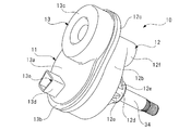
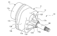
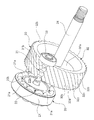
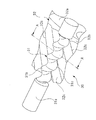
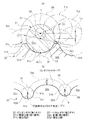
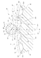
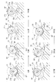
図1は減速機構付モータをコネクタ接続部側から見た斜視図を、図2は減速機構付モータを出力軸側から見た斜視図を、図3は減速機構付モータの内部構造を説明する斜視図を、図4はピニオンギヤとヘリカルギヤとの噛み合い部分を拡大した斜視図を、図5(a)は図4のA-A線に沿う断面図,(b)は斜歯の形状が噛合凸部の形状に基づいて決まることを説明する説明図を、図6はピニオンギヤおよびヘリカルギヤの詳細形状を説明する説明図を、図7はピニオンギヤとヘリカルギヤとの噛み合い動作を説明する説明図をそれぞれ示している。
図1および図2に示される減速機構付モータ10は、例えば、自動車等の車両に搭載されるワイパ装置(図示せず)の駆動源に用いられるものである。より具体的には、減速機構付モータ10は、フロントガラス(図示せず)の前方側に配置され、かつフロントガラス上に揺動自在に設けられたワイパ部材(図示せず)を、所定の払拭範囲(下反転位置と上反転位置との間)で揺動させるようになっている。
減速機構付モータ10は、その外郭を形成するハウジング11を備えている。そして、このハウジング11の内部には、図3に示されるように、ブラシレスモータ20および減速機構30が回転自在に収容されている。ここで、ハウジング11は、アルミ製のケーシング12およびプラスチック製のカバー部材13から形成されている。
図1および図2に示されるように、ケーシング12は、溶融されたアルミ材料を射出成形することにより、略お椀型形状に形成されている。具体的には、ケーシング12は、底壁部12aと、その周囲に一体に設けられた側壁部12bと、ケーシング12の開口側(図中左側)に設けられたケースフランジ12cと、を備えている。
底壁部12aの略中央部分には、出力軸34を回転自在に保持する筒状のボス部12dが一体に設けられている。ボス部12dの径方向内側には、所謂メタルと呼ばれる筒状の軸受部材(図示せず)が装着されており、これにより出力軸34は、ボス部12dに対してがたつくこと無くスムーズに回転できるようになっている。
また、ボス部12dの径方向外側には、ボス部12dを中心に放射状に延びる複数の補強リブ12eが一体に設けられている。これらの補強リブ12eは、ボス部12dと底壁部12aとの間に配置され、外観が略三角形形状に形成されている。これらの補強リブ12eは、ボス部12dの底壁部12aに対する固定強度を高めるものであって、ボス部12dが底壁部12aに対して傾斜する等の不具合の発生を防止している。
さらに、底壁部12aのボス部12dから偏心した位置には、軸受部材収容部12fが一体に設けられている。軸受部材収容部12fは有底筒状に形成され、ボス部12dの突出方向と同じ方向に突出されている。そして、軸受部材収容部12fの内部には、図3に示されるように、ピニオンギヤ31の先端側を回動自在に支持するボールベアリング33が収容されるようになっている。
なお、図2に示されるように、ボス部12dと出力軸34との間には、止め輪12gが設けられており、これにより、出力軸34がボス部12dの軸方向にがたつくことが防止される。よって、減速機構付モータ10の静粛性が確保されている。
ハウジング11を形成するカバー部材13は、溶融されたプラスチック材料を射出成形することにより、略平板状に形成されている。具体的には、カバー部材13は、本体部13aと、その周囲に一体に設けられたカバーフランジ13bと、を備えている。そして、カバーフランジ13bは、Oリング等のシール部材(図示せず)を介して、ケースフランジ12cに突き当てられている。これにより、ハウジング11内への雨水等の進入が防止される。
また、カバー部材13の本体部13aには、ブラシレスモータ20(図3参照)を収容するモータ収容部13cが一体に設けられている。モータ収容部13cは有底筒状に形成され、ケーシング12側とは反対側に突出されている。モータ収容部13cは、カバー部材13をケーシング12に装着した状態で、ケーシング12の軸受部材収容部12fと対向している。そして、モータ収容部13cの内側には、ブラシレスモータ20のステータ21(図3参照)が固定されるようになっている。
さらに、カバー部材13の本体部13aには、車両側の外部コネクタ(図示せず)が接続されるコネクタ接続部13dが一体に設けられている。コネクタ接続部13dの内側には、ブラシレスモータ20に駆動電流を供給するための複数のターミナル部材13e(図1では1つのみ示す)の一端側が露出されている。そして、これらのターミナル部材13eを介して、外部コネクタからブラシレスモータ20に駆動電流が供給される。
なお、複数のターミナル部材13eの他端側とブラシレスモータ20との間には、ブラシレスモータ20の回転状態(回転数や回転方向等)を制御する制御基板(図示せず)が設けられている。これにより、出力軸34の先端側に固定されたワイパ部材が、フロントガラス上の所定の払拭範囲で揺動される。なお、制御基板は、カバー部材13における本体部13aの内側に固定されている。
ハウジング11の内部に収容されるブラシレスモータ20は、図3に示されるように、環状のステータ(固定子)21を備えている。ステータ21は、カバー部材13におけるモータ収容部13c(図1参照)の内部に、回り止めされた状態で固定されている。
ステータ21は、複数の薄い鋼板(磁性体)を積層して形成され、その径方向内側には複数のティース(図示せず)が設けられている。そして、これらのティースには、U相,V相,W相のコイル21aが、それぞれ集中巻き等により複数回巻装されている。これにより、それぞれのコイル21aに所定のタイミングで交互に駆動電流を供給することで、ステータ21の径方向内側に設けられた回転体としてのロータ22が、所定の回転方向に所定の駆動トルクで回転される。
ステータ21の径方向内側には、微小隙間(エアギャップ)を介してロータ(回転子)22が回転自在に設けられている。ロータ22は、複数の薄い鋼板(磁性体)を積層して略円柱状に形成されたロータ本体22aを備えている。そして、ロータ22の外周部分には、筒状の永久磁石22bが設けられている。ここで、永久磁石22bは、その周方向にN極,S極,・・・と交互に磁極が並ぶよう着磁されている。そして、永久磁石22bはロータ本体22aに対して、接着剤等により一体回転可能に強固に固定されている。
このように、本実施の形態に係るブラシレスモータ20は、ロータ本体22aの表面に永久磁石22bを固定したSPM(Surface Permanent Magnet)構造のブラシレスモータとなっている。ただし、SPM構造のブラシレスモータに限らず、ロータ本体22aに複数の永久磁石を埋め込んだIPM(Interior Permanent Magnet)構造のブラシレスモータを採用することもできる。
また、筒状に形成された1つの永久磁石22bに換えて、ロータ本体22aの軸線と交差する方向に沿う断面が略円弧状に形成された複数の永久磁石を、ロータ本体22aの周方向に磁極が交互に並ぶよう等間隔で配置したものであっても良い。さらには、永久磁石22bの極数は、ブラシレスモータ20の仕様に応じて、2極あるいは4極以上等、任意に設定することができる。
ハウジング11の内部に収容される減速機構30は、図3に示されるように、略棒状に形成されたピニオンギヤ(第1ギヤ)31と、略円盤状に形成されたヘリカルギヤ(第2ギヤ)32とを備えている。ここで、ピニオンギヤ31の軸線およびヘリカルギヤ32の軸線は互いに平行となっている。これにより、減速機構30では、互いの軸線が交差するウォームおよびウォームホイールを備えたウォーム減速機よりも、その体格をよりコンパクトにすることができる。
また、ピニオンギヤ31は減速機構付モータ10の入力側(駆動源側)に配置され、ヘリカルギヤ32は減速機構付モータ10の出力側(駆動対象物側)に配置されている。つまり、減速機構30は、歯数が少ないピニオンギヤ31の高速回転を、歯数が多いヘリカルギヤ32の低速回転に減速するようになっている。
ここで、ピニオンギヤ31の基端側は、ロータ本体22aの回転中心に圧入等により強固に固定されており、ピニオンギヤ31はロータ本体22aと一体回転するようになっている。つまり、ピニオンギヤ31は、ロータ22によって回転されるようになっている。また、ピニオンギヤ31の先端側は、ボールベアリング33によって回動自在に支持されている。さらには、ヘリカルギヤ32の回転中心には、出力軸34の基端側が圧入等により強固に固定されており、出力軸34はヘリカルギヤ32と一体回転するようになっている。
減速機構30を形成するピニオンギヤ31は金属製であって、図3ないし図6に示されるような形状をなしている。具体的には、ピニオンギヤ31は、略円柱状に形成されたピニオン本体31aを有しており、その軸方向基端側がロータ本体22aに固定され、軸方向先端側がボールベアリング33に回動自在に支持されている。つまり、ピニオンギヤ31(ピニオン本体31a)の回転中心C1は、ロータ本体22aおよびボールベアリング33の回転中心に一致している。
ピニオン本体31aの軸方向に沿うヘリカルギヤ32との対向部分には、螺旋状歯(第1歯部)31bが一体に設けられている。具体的には、螺旋状歯31bの軸方向長さは、ヘリカルギヤ32の軸方向長さよりも若干長い長さ寸法に設定されている。これにより螺旋状歯31bは、ヘリカルギヤ32に確実に噛み合うことができる。そして、螺旋状歯31bは、ピニオンギヤ31の軸方向に螺旋状に連続して延びており、ピニオンギヤ31には、1つの螺旋状歯31bのみが設けられている。すなわち、ピニオンギヤ31の歯数は「1」に設定されている。
図5(a)に示されるように、螺旋状歯31bは、ピニオンギヤ31の軸方向と直交する方向に沿う断面形状が円形となるように形成されている。そして、螺旋状歯31bの中心C2は、ピニオンギヤ31の回転中心C1に対して、所定距離Lの分だけ偏心(オフセット)されている。つまり、中心C2の回転中心C1に対する偏心量はLとなっている。これにより、螺旋状歯31bの中心C2は、ピニオンギヤ31の回転に伴って、第1回転軌跡OCを辿るようになっている。言い換えれば、第1回転軌跡OCは、螺旋状歯31bの基準円を形成している。
また、図5(a)に示されるように、ピニオンギヤ31の回転中心C1から螺旋状歯31bの中心C2に向けて(図中下方に向けて)補助線ALを引き、この補助線ALをさらに螺旋状歯31bの表面まで延ばすと、補助線ALと螺旋状歯31bの表面とが交差する。この交差点が、噛合凸部31cの頂点BPとなっている。ここで、頂点BPは、ピニオンギヤ31の径方向外側の端部(表面)において、噛合凸部31cに設けられている。また、噛合凸部31cは、螺旋状歯31bの一部である噛み合い部を構成しており、当該噛合凸部31cにおいても螺旋状となっており、ヘリカルギヤ32の隣り合う斜歯32c同士の間の噛合凹部32dに入り込む(噛み合う)ようになっている。
このように、噛合凸部31cは、螺旋状歯31bの頂点BP寄りの部分に設けられている。そして、噛合凸部31cは、ピニオンギヤ31の軸方向と直交する方向に沿う断面形状が円弧状に形成され、かつピニオンギヤ31の回転中心C1から所定距離Lの分だけ偏心した位置に曲率中心C2が設けられている。すなわち、噛合凸部31cの曲率中心C2と、螺旋状歯31bの中心C2は、互いに一致している。
ここで、噛合凸部31cの頂点BPは、ピニオンギヤ31の回転に伴って、第2回転軌跡PRを辿るようになっている。つまり、第2回転軌跡PRの直径寸法D1の方が、螺旋状歯31bの直径寸法D2よりも大きくなっている(D1>D2)。
なお、図5(a)においては、噛合凸部31cの頂点BPが、ヘリカルギヤ32の噛合凹部32dに入り込んだ状態、すなわち、噛合凸部31cと噛合凹部32dとが互いに噛み合わされた状態を示している。
そして、ピニオンギヤ31が回転すると、当該ピニオンギヤ31の回転に伴って、噛合凸部31cの頂点BPがヘリカルギヤ32に設けられた複数の噛合凹部32dに対して、次々と入り込むようになっている。これにより、ヘリカルギヤ32がピニオンギヤ31よりも減速された状態で回転される。このとき、螺旋状歯31bは、具体的には、図5(a)の二点鎖線で示される軌跡Tr1から軌跡Tr2および軌跡Tr3を辿って、隣の噛合凹部32dに入り込むようになっている。
これにより、噛合凸部31cの曲率中心C2は、図5(a)の破線で示されるように、連続した複数の円弧からなる動作軌跡Sepを辿るようになる。なお、この動作軌跡Sepは、ピニオンギヤ31およびヘリカルギヤ32の回転に伴って、ヘリカルギヤ32の周囲に全周(360度)に亘って形成されるようになっている。
減速機構30を形成するヘリカルギヤ32はプラスチック製であって、図3ないし図6に示されるような形状をなしている。具体的には、ヘリカルギヤ32は、略円盤状に形成されたギヤ本体32aを備えており、当該ギヤ本体32aの中心部分に、出力軸34の基端側が圧入等により強固に固定されている。また、ギヤ本体32aの外周部分には、出力軸34の軸方向に延びる筒状部32bが一体に設けられている。
筒状部32bの径方向外側には、筒状部32bの周方向に並ぶようにして、複数の斜歯(第2歯部)32cが一体に設けられている。これらの斜歯32cは、ピニオンギヤ31の軸方向に対して所定角度で傾斜しており、これにより、螺旋状歯31bの回転に伴って、ヘリカルギヤ32は回転される。ここで、ヘリカルギヤ32に設けられる斜歯32cの数は「40」に設定されている。すなわち、本実施の形態では、ピニオンギヤ31およびヘリカルギヤ32からなる減速機構30の減速比は「40」となっている。なお、ピニオンギヤ31とヘリカルギヤ32との噛み合い動作については、後で詳述する。
図5および図6に示されるように、隣り合う斜歯32c同士の間には、噛合凹部32dが設けられている。よって、噛合凹部32dにおいても、斜歯32cと同様に、ピニオンギヤ31の軸方向に対して所定角度で傾斜している。そして、噛合凹部32dには、ピニオンギヤ31の噛合凸部31cが入り込んで噛み合わされるようになっている。
ここで、噛合凹部32dは、ピニオンギヤ31の軸方向と直交する方向に沿う断面形状が円弧状に形成され、その曲率中心C3は、ヘリカルギヤ32の基準円TC上に配置されている。そして、ヘリカルギヤ32の基準円TCには、螺旋状歯31bの基準円(=第1回転軌跡OC)が外接するようになっている。
したがって、本来であればヘリカルギヤ32の周方向に沿う斜歯32cの中心において、ヘリカルギヤ32の直径寸法はR(ヘリカルギヤ32の回転中心C4と第1回転軌跡OCとの距離の2倍)となるが、本実施の形態では、螺旋状歯31bの断面形状が、噛合凸部31cの形状に倣って円形となっている。そのため、ピニオンギヤ31を容易に製造できる一方で、螺旋状歯31bの頂点BP側とは反対側に、所定の肉厚の肉厚部Tが存在することになる。
そこで、螺旋状歯31bと斜歯32cとの干渉(接触)を防ぐために、斜歯32cの歯たけを逃げ量Eの分だけ小さくして、螺旋状歯31bと斜歯32cとを接触させない歯たけHに設定している。ここで、斜歯32cの歯たけHは、噛合凹部32dの最も深い部分を通過する歯底円BCからの高さとなっている。また、隣り合う噛合凹部32d同士のなす角度AGは、ヘリカルギヤ32の歯数が「40」であって、噛合凹部32dの数も「40」になるため、本実施の形態では「9度」となっている。
より具体的には、図5(a)および図5(b)に示されるように、斜歯32cの形状および噛合凹部32dの形状は、それぞれ螺旋状歯31b(噛合凸部31c)の形状に基づいて決定される。なお、図5(b)においては、斜歯32cおよび噛合凹部32dの形状が、噛合凸部31cの曲率中心C2の動作軌跡Sepによって決定されることを判り易くするために、実際の斜歯32cの形状(図5(a)参照)とは異ならせて模式的に示している。
すなわち、図5(b)に示されるように、ヘリカルギヤ32を、ピニオンギヤ31の軸方向から見たときに、斜歯32cの形状は、噛合凸部31cの曲率中心C2の動作軌跡Sep(図中破線)から、噛合凸部31cの曲率半径rの分だけヘリカルギヤ32の径方向内側にずれた曲線CL(図中実線のオフセットカーブ)の形状となっている。言い換えれば、動作軌跡Sep上の複数の点を、曲率半径rの分だけヘリカルギヤ32の径方向内側にそれぞれずらして、かつこれらの点を繋ぐと曲線CLとなる。
一方、噛合凹部32dの形状は、噛合凸部31cの曲率中心C2の動作軌跡Sep(図中破線)を形成する点(図示せず)のうちの、ヘリカルギヤ32の最も径方向内側に配置される点P、言い換えれば曲率中心C2の下死点を中心に、噛合凸部31cの曲率半径rを半径とする円弧AR(図中実線の下方に窪んだ円弧の部分)の形状となっている。
そして、これらの曲線CLおよび円弧ARは、ヘリカルギヤ32の周囲に交互に連なるようにして全周(360度)に亘って設けられている。このように、斜歯32cおよび噛合凹部32dの形状は、噛合凸部31cの曲率中心C2の動作軌跡Sepによって決定されるが、図6に示されるように、噛合凹部32dの直径寸法SRは、螺旋状歯31bの直径寸法D2よりも若干大きい寸法となっている(SR>D2)。この寸法差(SR-D2)の半分(1/2)が所謂バックラッシ(歯面間の遊び)となっている。これにより、ピニオンギヤ31とヘリカルギヤ32との噛み合い動作が滑らかになるようにしている。
なお、斜歯32cおよび噛合凹部32dの形状を決定する際には、必要とされるバックラッシ量(SR-D2)/2を考慮するようにする。具体的には、噛合凸部31cの曲率半径rに、バックラッシ量(SR-D2)/2を上乗せして、曲線CLおよび円弧AR(図5(b)参照)の形状を決定するようにする。このようにして、噛合凸部31cの曲率中心C2の動作軌跡Sepを基準に、バックラッシ量(SR-D2)/2を盛り込むことで、出来上がった減速機構30のスムーズな動作が保証される。
ただし、バックラッシ量(SR-D2)/2は、減速機構30(図3参照)に必要とされる減速比や、減速機構付モータ10(図1参照)の体格等に合わせて、適宜決定するようにする。
ここで、斜歯32cおよび噛合凹部32dを形成する噛合凸部31cの曲率中心C2の動作軌跡Sepの座標x,yは、下記式(1),(2)により規定される。
x=a×sinθ-e×sin(Z+1)×θ ・・・(1)
y=a×cosθ-e×cos(Z+1)×θ ・・・(2)
a:噛合凸部31cの曲率中心C2とヘリカルギヤ32の回転中心C4との距離(図6において「R/2+2×L」)
Z:斜歯32cの数(本実施の形態では「40」)
e:ピニオンギヤ31の回転中心C1に対する噛合凸部31cの曲率中心C2の偏心量(図6において「L」)
θ:ピニオンギヤ31の回転角度
すなわち、噛合凸部31cの曲率中心C2の動作軌跡Sepは、所謂「エピトロコイド曲線(外トロコイド曲線)」であって、これに基づいてヘリカルギヤ32の斜歯32cおよび噛合凹部32dを決定することで、ヘリカルギヤ32の設計を容易にしつつ、ピニオンギヤ31を確実に噛み合わせられるようにしている。言い換えれば、ピニオンギヤ31の螺旋状歯31b(噛合凸部31c)の形状に合わせ込むようにして、ヘリカルギヤ32の斜歯32cおよび噛合凹部32dをトライ・アンド・エラーで調整する必要が無く、減速機構30を容易に量産可能となっている。
y=a×cosθ-e×cos(Z+1)×θ ・・・(2)
a:噛合凸部31cの曲率中心C2とヘリカルギヤ32の回転中心C4との距離(図6において「R/2+2×L」)
Z:斜歯32cの数(本実施の形態では「40」)
e:ピニオンギヤ31の回転中心C1に対する噛合凸部31cの曲率中心C2の偏心量(図6において「L」)
θ:ピニオンギヤ31の回転角度
すなわち、噛合凸部31cの曲率中心C2の動作軌跡Sepは、所謂「エピトロコイド曲線(外トロコイド曲線)」であって、これに基づいてヘリカルギヤ32の斜歯32cおよび噛合凹部32dを決定することで、ヘリカルギヤ32の設計を容易にしつつ、ピニオンギヤ31を確実に噛み合わせられるようにしている。言い換えれば、ピニオンギヤ31の螺旋状歯31b(噛合凸部31c)の形状に合わせ込むようにして、ヘリカルギヤ32の斜歯32cおよび噛合凹部32dをトライ・アンド・エラーで調整する必要が無く、減速機構30を容易に量産可能となっている。
上述の観点とは別の観点で見ると、ピニオンギヤ31およびヘリカルギヤ32の形状は、以下の種々の式をそれぞれ満たすように決定される。
具体的には、ピニオンギヤ31の形状は、下記式(3)に基づいて決定される。
(D2÷2+L)×2=D1 ・・・(3)
D2:螺旋状歯31bの直径寸法
L:偏心量
D1:第2回転軌跡PRの直径寸法
また、ヘリカルギヤ32の形状は、下記式(4)ないし(6)に基づいて決定される。
D2:螺旋状歯31bの直径寸法
L:偏心量
D1:第2回転軌跡PRの直径寸法
また、ヘリカルギヤ32の形状は、下記式(4)ないし(6)に基づいて決定される。
L×2×減速比=R ・・・(4)
L:偏心量
R:斜歯32cの中心の直径寸法
減速比:本実施の形態では「40」
すなわち、上記式(4)に示されるように、ピニオンギヤ31およびヘリカルギヤ32(減速機構30)の減速比は、噛合凸部31cの曲率中心C2とピニオンギヤ31の回転中心C1との間の第1距離(=偏心量L)と、噛合凹部32dの曲率中心C3とヘリカルギヤ32の回転中心C4との間の第2距離(=R/2)との比に等しくなっている。
L:偏心量
R:斜歯32cの中心の直径寸法
減速比:本実施の形態では「40」
すなわち、上記式(4)に示されるように、ピニオンギヤ31およびヘリカルギヤ32(減速機構30)の減速比は、噛合凸部31cの曲率中心C2とピニオンギヤ31の回転中心C1との間の第1距離(=偏心量L)と、噛合凹部32dの曲率中心C3とヘリカルギヤ32の回転中心C4との間の第2距離(=R/2)との比に等しくなっている。
SR=D2+α ・・・(5)
SR:噛合凹部32dの直径寸法
D2:螺旋状歯31bの直径寸法
α:微少量
D2÷2-L×2+β=E ・・・(6)
D2:螺旋状歯31bの直径寸法
L:偏心量
β:微少量
E:斜歯32cの歯たけの逃げ量
ここで、上記式(5)および(6)における微少量α,βは、噛合凸部31cと噛合凹部32dとをスムーズに噛み合わせるための設定値、つまり上述したバックラッシ(歯面間の遊び)に相当し、斜歯32cの歯先の詳細な形状(微小なカーブやテーパ形状等)に応じて適宜微小な最適値に設定される。
SR:噛合凹部32dの直径寸法
D2:螺旋状歯31bの直径寸法
α:微少量
D2÷2-L×2+β=E ・・・(6)
D2:螺旋状歯31bの直径寸法
L:偏心量
β:微少量
E:斜歯32cの歯たけの逃げ量
ここで、上記式(5)および(6)における微少量α,βは、噛合凸部31cと噛合凹部32dとをスムーズに噛み合わせるための設定値、つまり上述したバックラッシ(歯面間の遊び)に相当し、斜歯32cの歯先の詳細な形状(微小なカーブやテーパ形状等)に応じて適宜微小な最適値に設定される。
次に、以上のように形成された減速機構30の動作、つまりピニオンギヤ31とヘリカルギヤ32との噛み合い動作について、図面を用いて詳細に説明する。
図7の「0度」に示される状態は、図5(a)に示される状態と同じ状態である。この状態では、ピニオンギヤ31における噛合凸部31cの頂点BPは、ヘリカルギヤ32の噛合凹部32dに入り込んだ状態となっている。つまり、噛合凸部31cおよび噛合凹部32dは、互いに噛み合わされた状態となっている。
そして、減速機構30の動作中においては、噛合凸部31cと噛合凹部32dとが互いに噛み合わされた状態、つまり図7の「0度」に示される状態(図5(a)に示される状態)が、螺旋状歯31bの軸方向に徐々に移動していくことになる。すると、噛合凹部32dはピニオンギヤ31の軸方向に対して傾斜しているため、これにより、ピニオンギヤ31よりも減速された状態でヘリカルギヤ32は回転される。このように、ヘリカルギヤ32は、ピニオンギヤ31の回転に伴い回転するようになっている。
ここで、螺旋状歯31bの軸方向に沿う一部分(例えば、図4のA-A線に沿う部分)のみに着目すると、図7の「0度」に示される状態においてピニオンギヤ31が反時計回り方向に回転すると、これに伴い噛合凸部31cの頂点BPも反時計回り方向に回転される。これにより、噛合凸部31cが「75度」→「133度」→「190度」→「227度」→「266度」のように回転していき、1つの斜歯32cを乗り越える。その後、図7の「360度」に示される状態のように、1回転された噛合凸部31cは、隣の噛合凹部32dに噛み合わされる(図中白丸印の移動状態参照)。
このように、螺旋状歯31bが1回転すると、ヘリカルギヤ32は斜歯32cの1つ分(噛合凹部32dの1つ分)だけ回転される。すなわち、ピニオンギヤ31が1回転する間に、ヘリカルギヤ32は9度分だけ回転される。言い換えれば、ピニオンギヤ31が40回転すると、漸くヘリカルギヤ32が1回転するようになっている(=減速比「40」)。これにより、ヘリカルギヤ32がピニオンギヤ31の40倍の回転トルク(高トルク)で回転される。
以上詳述したように、実施の形態1によれば、ピニオンギヤ31に螺旋状の1つの噛合凸部31cを設け、ヘリカルギヤ32に噛合凸部31cが噛み合わされる複数の噛合凹部32dを設け、これらの噛合凸部31cおよび噛合凹部32dが、それぞれピニオンギヤ31の軸方向と直交する方向に沿う断面形状が円弧状となるように形成されており、斜歯32cの形状および噛合凹部32dの形状が、螺旋状歯31bに設けられた噛合凸部31cの形状に基づいて決められている。
したがって、ピニオンギヤ31およびヘリカルギヤ32を、互いに噛み合い状態を悪くすることが無い円弧状の凹凸の噛み合い構造にでき、かつピニオンギヤ31の歯数を1つとしつつヘリカルギヤ32の歯数を多くして(本実施の形態では「40」)歯数差を容易に大きくすることができる。よって、減速機構30の体格を大きくすること無く、減速比をより大きくすることが可能となる。
また、斜歯32cの形状および噛合凹部32dの形状が、螺旋状歯31bに設けられた噛合凸部31cの形状に基づいて決められるので、ヘリカルギヤ32の設計を容易にでき、かつピニオンギヤ31を確実に噛み合わせられるようにできる。したがって、ピニオンギヤ31の噛合凸部31cの形状に合わせ込むようにして、ヘリカルギヤ32の斜歯32cおよび噛合凹部32dをトライ・アンド・エラーで調整する必要が無く、減速機構30を容易に量産することが可能となる。
さらに、ピニオンギヤ31とヘリカルギヤ32との噛み合い部分、つまり螺旋状歯31b(噛合凸部31c)と、斜歯32cおよび噛合凹部32dとの間に、互いの噛み合い動作を滑らかにするバックラッシ(歯面間の遊び)が設けられているので、減速機構30をスムーズに動作させることができ、ひいては減速機構付モータ10の静粛性を向上させることが可能となる。
また、噛合凸部31cの曲率中心C2の動作軌跡Sepの座標x,yが、上記式(1),(2)により規定されているので、ヘリカルギヤ32の設計を容易にすることができ、かつピニオンギヤ31を確実に噛み合わせられるようにできる。
次に、本発明に係る種々の実施の形態について、図面を用いて詳細に説明する。なお、上述した実施の形態1と同様の機能を有する部分については同一の記号を付し、その詳細な説明を省略する。
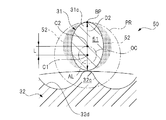
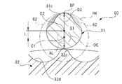
図8は実施の形態2を示す図5(a)に対応した図を、図9は実施の形態3を示す図5(a)に対応した図を、図10は実施の形態4(フェースギヤ)を説明する説明図を、図11は実施の形態5(やまば歯車)を説明する説明図を、図12は実施の形態6(遊星歯車減速機構)を示す斜視図を、図13は図12の遊星歯車減速機構を示す分解斜視図を、図14は実施の形態7(他の遊星歯車減速機構)を示す斜視図をそれぞれ示している。
[実施の形態2]
図8に示されるように、実施の形態2に係る減速機構50では、ピニオンギヤ31に設けられる螺旋状歯(第1歯部)51の形状のみが異なっている。具体的には、螺旋状歯51は、ピニオンギヤ31の軸方向と直交する方向に沿う断面形状が略楕円形形状となるように形成されている。具体的には、噛合凸部31cの頂点BPと、ピニオンギヤ31の回転中心C1と、を結んだ補助線ALを中心に、螺旋状歯51の両側を所定量削ぎ落とした形状になっている。より具体的には、補助線ALを中心とした螺旋状歯51の両側の一対の円弧状空間52(網掛け部分)の部分を、それぞれ削ぎ落とした形状になっている。このとき、噛合凸部31cの頂点BPを有する円弧状部分の曲率中心が、実施の形態1と同じC2となるように、削ぎ落とすようにする。
図8に示されるように、実施の形態2に係る減速機構50では、ピニオンギヤ31に設けられる螺旋状歯(第1歯部)51の形状のみが異なっている。具体的には、螺旋状歯51は、ピニオンギヤ31の軸方向と直交する方向に沿う断面形状が略楕円形形状となるように形成されている。具体的には、噛合凸部31cの頂点BPと、ピニオンギヤ31の回転中心C1と、を結んだ補助線ALを中心に、螺旋状歯51の両側を所定量削ぎ落とした形状になっている。より具体的には、補助線ALを中心とした螺旋状歯51の両側の一対の円弧状空間52(網掛け部分)の部分を、それぞれ削ぎ落とした形状になっている。このとき、噛合凸部31cの頂点BPを有する円弧状部分の曲率中心が、実施の形態1と同じC2となるように、削ぎ落とすようにする。
以上のように形成した実施の形態2においても、実施の形態1と同様の作用効果を奏することができる。これに加えて、実施の形態2では、実施の形態1に係る減速機構30の螺旋状歯31b(図5(a)参照)に比して、一対の円弧状空間52の部分の容積を減らすことができるので、ピニオンギヤ31の小型軽量化を図ることが可能となる。
[実施の形態3]
図9に示されるように、実施の形態3に係る減速機構60では、ピニオンギヤ31に設けられる螺旋状歯(第1歯部)61の形状のみが異なっている。具体的には、螺旋状歯61は、ピニオンギヤ31の軸方向と直交する方向に沿う断面形状が略扇形形状(略おにぎり形状)となるように形成されている。具体的には、噛合凸部31cの頂点BPと、ピニオンギヤ31の回転中心C1と、を結んだ補助線ALを中心に、螺旋状歯61の両側でかつ頂点BP寄りの部分を所定量削ぎ落とした形状になっている。具体的には、補助線ALを中心とした螺旋状歯61の両側でかつ頂点BP寄りの一対の円弧状空間62(網掛け部分)の部分を、それぞれ削ぎ落とした形状になっている。このとき、噛合凸部31cの頂点BPを有する円弧状部分の曲率中心が、実施の形態1と同じC2となるように、削ぎ落とすようにする。
図9に示されるように、実施の形態3に係る減速機構60では、ピニオンギヤ31に設けられる螺旋状歯(第1歯部)61の形状のみが異なっている。具体的には、螺旋状歯61は、ピニオンギヤ31の軸方向と直交する方向に沿う断面形状が略扇形形状(略おにぎり形状)となるように形成されている。具体的には、噛合凸部31cの頂点BPと、ピニオンギヤ31の回転中心C1と、を結んだ補助線ALを中心に、螺旋状歯61の両側でかつ頂点BP寄りの部分を所定量削ぎ落とした形状になっている。具体的には、補助線ALを中心とした螺旋状歯61の両側でかつ頂点BP寄りの一対の円弧状空間62(網掛け部分)の部分を、それぞれ削ぎ落とした形状になっている。このとき、噛合凸部31cの頂点BPを有する円弧状部分の曲率中心が、実施の形態1と同じC2となるように、削ぎ落とすようにする。
以上のように形成した実施の形態3においても、実施の形態1と同様の作用効果を奏することができる。これに加えて、実施の形態3では、実施の形態1に係る減速機構30の螺旋状歯31b(図5(a)参照)に比して、一対の円弧状空間62の部分の容積を減らすことができるので、ピニオンギヤ31の小型軽量化を図ることが可能となる。また、実施の形態2に係る減速機構50(図8参照)に比して、削ぎ落とす部分が少ないので、螺旋状歯61の剛性を低下させずに済む。
なお、実施の形態2,3のように、補助線ALを中心としてその両側で対称形状とせずに、補助線ALを中心としてその両側で非対称形状にしても良い。また削ぎ落とす部分の形状については、実施の形態2,3のような円弧状に限らず、多角形状等でも良く、その形状は問わない。
[実施の形態4]
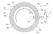
図10に示されるように、実施の形態4に係る減速機構80では、ピニオンギヤ31に噛み合わせられるギヤが、図3に示されるようなヘリカルギヤ32に換えて、フェースギヤ81となっている点のみが異なっている。つまり、本実施の形態では、フェースギヤ81が本発明における第2ギヤを構成している。具体的には、フェースギヤ81の軸線およびピニオンギヤ31の軸線は、互いに直交しており、所謂食い違い軸のギヤ機構を形成している。
図10に示されるように、実施の形態4に係る減速機構80では、ピニオンギヤ31に噛み合わせられるギヤが、図3に示されるようなヘリカルギヤ32に換えて、フェースギヤ81となっている点のみが異なっている。つまり、本実施の形態では、フェースギヤ81が本発明における第2ギヤを構成している。具体的には、フェースギヤ81の軸線およびピニオンギヤ31の軸線は、互いに直交しており、所謂食い違い軸のギヤ機構を形成している。
フェースギヤ81は環状に形成され、その表面には、図10にされるように、複数の斜歯32cと、隣り合う斜歯32c同士の間に設けられる複数の噛合凹部32dと、が設けられている。そして、複数の斜歯32cおよび複数の噛合凹部32dは、ピニオンギヤ31の軸方向に対して傾斜され、かつフェースギヤ81の周方向に並べられている。これにより、実施の形態1と同様に、ピニオンギヤ31の噛合凸部31cは、フェースギヤ81の噛合凹部32dに噛み合わされる。
なお、図中矢印R1の方向へのピニオンギヤ31の高速回転は、図中矢印R2の方向へのフェースギヤ81の低速回転となる。そして、高トルク化された回転力は、フェースギヤ81に設けられた出力部(図示せず)から駆動対象物(図示せず)に向けて出力される。
以上のように形成した実施の形態4においても、実施の形態1と同様の作用効果を奏することができる。
[実施の形態5]
図11に示されるように、実施の形態5に係る減速機構90では、ピニオンギヤ31およびヘリカルギヤ32からなる一対の減速機構30を、突き合わせ部TPを境に互いに鏡像対称となるように突き合わせた構造を採用する。つまり、互いに突き合わされた一対のヘリカルギヤ32は、一体化された状態ではやまば歯車(第2ギヤ)91となる。そして、やまば歯車91の山歯(第2歯部)91aは、互いに鏡像対称となるように向き合った斜歯32cにより、その外観が略V字形状となるように形成されている。したがって、隣り合う山歯91a同士の間には、外観が略V字形状となるように互いに向き合った噛合凹部32dが設けられている。
図11に示されるように、実施の形態5に係る減速機構90では、ピニオンギヤ31およびヘリカルギヤ32からなる一対の減速機構30を、突き合わせ部TPを境に互いに鏡像対称となるように突き合わせた構造を採用する。つまり、互いに突き合わされた一対のヘリカルギヤ32は、一体化された状態ではやまば歯車(第2ギヤ)91となる。そして、やまば歯車91の山歯(第2歯部)91aは、互いに鏡像対称となるように向き合った斜歯32cにより、その外観が略V字形状となるように形成されている。したがって、隣り合う山歯91a同士の間には、外観が略V字形状となるように互いに向き合った噛合凹部32dが設けられている。
さらに、互いに突き合わされた一対のピニオンギヤ31においては、一体化された状態でダブルピニオンギヤ(第1ギヤ)92を形成している。このダブルピニオンギヤ92には、互いに鏡像対称となるように向き合った一対の螺旋状歯31bが設けられている。つまり、これらの螺旋状歯31bは、それぞれ螺旋の方向が逆向きになっている。そして、これらの螺旋状歯31bの噛合凸部31cは、隣り合う山歯91a同士の間の噛合凹部32dにそれぞれ噛み合っている。
以上のように形成した実施の形態5においても、実施の形態1と同様の作用効果を奏することができる。これに加えて、実施の形態5では、一対の減速機構30を互いに鏡像対称となるように突き合わせた構造、つまり、やまば歯車の構造を採用するので、図11の矢印F1,F2に示されるように、やまば歯車91やダブルピニオンギヤ92をその軸方向に移動させようとするスラスト力を、相殺する(無くす)ことができる。
すなわち、ダブルピニオンギヤ92を、図中実線矢印方向や図中破線矢印方向に回転させたとしても、当該ダブルピニオンギヤ92や、これにより回転されるやまば歯車91は、軸方向に移動することが無い。よって、ダブルピニオンギヤ92およびやまば歯車91を収容するハウジング側の構造を、より簡素化することが可能となる。
[実施の形態6]
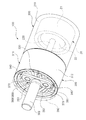
図12および図13に示されるように、実施の形態6においては、その全体形状が略円柱形状に形成された減速機構付モータ100となっている。この減速機構付モータ100は、略円柱形状に形成されたモータ部200と、同じく略円柱形状に形成された減速機構部300と、を備えており、これらは互いに同軸上に設けられている。
図12および図13に示されるように、実施の形態6においては、その全体形状が略円柱形状に形成された減速機構付モータ100となっている。この減速機構付モータ100は、略円柱形状に形成されたモータ部200と、同じく略円柱形状に形成された減速機構部300と、を備えており、これらは互いに同軸上に設けられている。
モータ部200は、減速機構付モータ100の外郭を形成する有底円筒状のモータハウジング210を備えており、このモータハウジング210の内部には、ブラシレスモータ20が収容されている。ブラシレスモータ20を形成するステータ21は、モータハウジング210の内壁に接着剤等(図示せず)により固定されており、ステータ21の径方向内側には、ロータ22が所定の隙間を介して回転自在に設けられている。そして、ロータ22の回転中心には、駆動軸220の軸方向基端部が、圧入等により強固に固定されている。このように、モータ部200は、ロータ22によって回転される駆動軸220を備えている。
また、減速機構部300は、減速機構付モータ100の外郭を形成する有底筒状のギヤハウジング310を備えている。このギヤハウジング310は、略円盤状に形成された底壁部311と、当該底壁部311に一体に設けられた円筒壁部312と、を備えている。また、底壁部311の中心部分には、駆動軸220の軸方向基端側(図13中下側)が挿通される挿通孔313が形成されている。ここで、挿通孔313の径方向内側には、駆動軸220の軸方向基端側を回転自在に支持する第1軸受B1が固定されている。これにより、駆動軸220は、ギヤハウジング310に対してスムーズに回転可能となっている。なお、第1軸受B1には、所謂メタルと呼ばれる円筒状の滑り軸受を採用している。
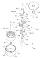
さらに、ギヤハウジング310の内部には、減速機構としての遊星歯車減速機構320が収容されている。この遊星歯車減速機構320は、駆動軸220により回転される太陽歯車(第1ギヤ)330と、当該太陽歯車330により回転される一対の遊星歯車(第2ギヤ)340と、これらの一対の遊星歯車340に噛み合わされる内歯車(リングギヤ)350と、を備えている。
太陽歯車330は、上述したピニオンギヤ31(図4参照)と全く同じものであって、螺旋状歯31bと噛合凸部31cとを備えている。そして、太陽歯車330の軸方向基端部は、駆動軸220の軸方向先端部に一体化して設けられている。すなわち、駆動軸220と太陽歯車330とは、それぞれ1つの部材(金属製)によって形成されており、かつ互いに同軸上に配置されている。よって、太陽歯車330は、駆動軸220によって回転される。
一対の遊星歯車340は、太陽歯車330を中心に互いに対向配置されており、かつ太陽歯車330の周囲を公転するようになっている。これらの遊星歯車340は、それぞれ互いに同じものであって、遊星歯車340の外周部分には、上述したヘリカルギヤ32(図3参照)と同じ斜歯32cが設けられている。そして、隣り合う斜歯32c同士の間には、太陽歯車330の噛合凸部31cが入り込む(噛み合う)噛合凹部32dが形成されている。よって、遊星歯車340は、太陽歯車330によって回転される。
また、一対の遊星歯車340は、キャリア360によりそれぞれ回転自在に支持されている。キャリア360は、第1部材370および第2部材380を、それぞれ互いに組み立てることで形成されている。第1部材370は、略長方形の板状に形成された第1本体部371を備えている。この第1本体部371の長手方向中央部には、駆動軸220の軸方向先端側が非接触の状態で挿通される挿通孔372が形成されている。さらに、第1本体部371の長手方向両側には、一対の遊星歯車340をそれぞれ回転自在に支持する一対の支軸373が設けられている。そして、これらの支軸373に回転自在に支持されたそれぞれの遊星歯車340の間に、太陽歯車330が挟まれるようにして設けられている。これにより、太陽歯車330に設けられた1つの噛合凸部31cが、一対の遊星歯車340のそれぞれに設けられた噛合凹部32dに対して、図5(a)に示される状態と同様にそれぞれ噛み合わされている。
また、キャリア360を形成する第2部材380は、略長方形の板状に形成された第2本体部381を備えている。この第2本体部381の長手方向中央部には、太陽歯車330の軸方向先端部が非接触の状態で挿通される挿通孔(図示せず)が形成されている。さらに、第2本体部381の長手方向両側には、一対の支軸373の端部を支持する一対の支持穴382が形成されている。また、第2本体部381の挿通孔に対応する部分には、有底筒状に形成された出力軸383の開口端部(図示せず)が固定されている。そして、出力軸383の開口端部の部分および第2本体部381の挿通孔の部分には、太陽歯車330の軸方向先端部を回転自在に支持する第2軸受B2が固定されている。これにより、太陽歯車330は、出力軸383に対してスムーズに回転可能となっている。なお、第2軸受B2においても、所謂メタルと呼ばれる円筒状の滑り軸受を採用している。このように、キャリア360は、一対の遊星歯車340を回転自在に支持するとともに、太陽歯車330と同軸の出力軸383を備えている。
さらに、ギヤハウジング310を形成する円筒壁部312の内側には、略円筒形状に形成された内歯車350が相対回転不能に固定されている。また、内歯車350の内周部分には、一対の遊星歯車340の斜歯32cが噛み合わされる複数の内歯351が設けられている。これらの内歯351においても、遊星歯車340に設けられた斜歯32cと同様の形状に形成されている。
また、ギヤハウジング310の開口側の部分(図13中上側の部分)は、略円盤状に形成されたギヤカバー390によって閉塞されている。これにより、組み立てられた遊星歯車減速機構320が、がたつかずにかつ分解されること無く、ギヤハウジング310の内部で作動可能となっている。また、ギヤカバー390の中心部分には、出力軸383が非接触の状態で挿通される挿通孔391が形成されている。そして、この挿通孔391の径方向内側には、出力軸383を回転自在に支持する第3軸受B3が固定されている。これにより、出力軸383は、ギヤカバー390に対してスムーズに回転可能となっている。なお、第3軸受B3においても、所謂メタルと呼ばれる円筒状の滑り軸受を採用している。
以上のように形成した実施の形態6においても、実施の形態1と同様の作用効果を奏することができる。
[実施の形態7]
図14に示されるように、実施の形態7においては、実施の形態6に比して、遊星歯車減速機構(減速機構)400の構造のみが異なっている。なお、実施の形態6と同様の機能を有する部分については同一の記号を付し、その詳細な説明を省略する。
図14に示されるように、実施の形態7においては、実施の形態6に比して、遊星歯車減速機構(減速機構)400の構造のみが異なっている。なお、実施の形態6と同様の機能を有する部分については同一の記号を付し、その詳細な説明を省略する。
実施の形態7の遊星歯車減速機構400では、一対の遊星歯車340が、ギヤハウジング310の底壁部311に回転自在に支持されている。具体的には、底壁部311には、一対の遊星歯車340をそれぞれ回転自在に支持する一対の支軸373が設けられている。つまり、一対の遊星歯車340は、一対の支軸373を中心に回転する自転運動を行うが、太陽歯車330を中心に回転する公転運動は行わない。
また、実施の形態7の遊星歯車減速機構400では、ギヤハウジング310に対して、内歯車350が回転自在に設けられている。具体的には、内歯車350は、円筒壁部312の内周壁に対して内歯車350の外周壁が非接触の状態で、ギヤハウジング310に配置されている。すなわち、実施の形態6では、キャリア360(図13参照)に支持された一対の遊星歯車340をギヤハウジング310に対して回転自在とし、内歯車350をギヤハウジング310に固定していた。これに対し、実施の形態7では、実施の形態6とは逆に、底壁部311によって一対の遊星歯車340がギヤハウジング310に固定され、内歯車350がギヤハウジング310に対して回転自在となっている。
そして、太陽歯車330と同軸の出力軸383は、内歯車350と一緒に回転するようになっている。具体的には、出力軸383は、平板状の動力伝達部材410を介して内歯車350に固定されている。動力伝達部材410は、略長方形に形成され、その長手方向両側には、固定ピン420が固定される固定孔411がそれぞれ設けられている。一対の固定ピン420の軸方向一側は、固定孔411にそれぞれ固定されている。また、一対の固定ピン420の軸方向他側は、内歯車350の軸方向一側の端部の固定孔(図示せず)にそれぞれ固定されている。これにより、動力伝達部材410は、内歯車350の回転に伴って、内歯車350と一緒に回転するようになっている。
そして、動力伝達部材410の長手方向中央部には、出力軸383の開口端部(図示せず)が固定されている。なお、動力伝達部材410の出力軸383が固定される部分には、第1本体部371に設けられた挿通孔372(図13参照)と同様の挿通孔(図示せず)が設けられている。
このように、実施の形態7では、出力軸383が内歯車350と共に回転するようになっている。すなわち、太陽歯車330と同軸の出力軸383は、動力伝達部材410を介して内歯車350に設けられている。
以上のように形成した実施の形態7においても、実施の形態1と同様の作用効果を奏することができる。
本発明は上記各実施の形態に限定されるものではなく、その要旨を逸脱しない範囲で種々変更可能であることは言うまでもない。例えば、上記各実施の形態では、減速機構30,50,60,80,90および遊星歯車減速機構320,400(減速機構付モータ10,100)を、車両に搭載されるワイパ装置の駆動源に適用したものを示したが、本発明はこれに限らず、パワーウィンドウ装置,サンルーフ装置,シートリフター装置等の他の駆動源にも適用することができる。
さらに、上記各実施の形態では、減速機構30,50,60,80,90および遊星歯車減速機構320,400をブラシレスモータ20で駆動する減速機構付モータ10,100を示したが、本発明はこれに限らず、ブラシレスモータ20に換えてブラシ付きモータを採用して、当該ブラシ付きモータで減速機構30,50,60,80,90および遊星歯車減速機構320,400を駆動させることもできる。
その他、上記各実施の形態における各構成要素の材質,形状,寸法,数,設置箇所等は、本発明を達成できるものであれば任意であり、上記各実施の形態に限定されない。
10 減速機構付モータ
11 ハウジング
12 ケーシング
12a 底壁部
12b 側壁部
12c ケースフランジ
12d ボス部
12e 補強リブ
12f 軸受部材収容部
12g 止め輪
13 カバー部材
13a 本体部
13b カバーフランジ
13c モータ収容部
13d コネクタ接続部
13e ターミナル部材
20 ブラシレスモータ
21 ステータ
21a コイル
22 ロータ(回転体)
22a ロータ本体
22b 永久磁石
30 減速機構
31 ピニオンギヤ(第1ギヤ)
31a ピニオン本体
31b 螺旋状歯(第1歯部)
31c 噛合凸部
32 ヘリカルギヤ(第2ギヤ)
32a ギヤ本体
32b 筒状部
32c 斜歯(第2歯部)
32d 噛合凹部
33 ボールベアリング
34 出力軸
50 減速機構(実施の形態2)
51 螺旋状歯(第1歯部)
52 円弧状空間
60 減速機構(実施の形態3)
61 螺旋状歯(第1歯部)
62 円弧状空間
80 減速機構(実施の形態4)
81 フェースギヤ(第2ギヤ)
90 減速機構(実施の形態5)
91 やまば歯車(第2ギヤ)
91a 山歯(第2歯部)
92 ダブルピニオンギヤ(第1ギヤ)
100 減速機構付モータ
200 モータ部
210 モータハウジング
220 駆動軸
300 減速機構部
310 ギヤハウジング
311 底壁部
312 円筒壁部
313 挿通孔
320 遊星歯車減速機構(減速機構)
330 太陽歯車(第1ギヤ)
340 遊星歯車(第2ギヤ)
350 内歯車
351 内歯
360 キャリア
370 第1部材
371 第1本体部
372 挿通孔
373 支軸
380 第2部材
381 第2本体部
382 支持穴
383 出力軸
390 ギヤカバー
391 挿通孔
400 遊星歯車減速機構(減速機構)
410 動力伝達部材
411 固定孔
420 固定ピン
AG 隣り合う噛合凹部32d同士のなす角度
AL 補助線
AR 円弧
B1 第1軸受
B2 第2軸受
B3 第3軸受
BC 歯底円
BP 噛合凸部31cの頂点
C1 ピニオンギヤ31の回転中心
C2 噛合凸部31cの曲率中心,螺旋状歯31bの中心
C3 噛合凹部32dの曲率中心
C4 ヘリカルギヤ32の回転中心
CL 曲線
D1 第2回転軌跡PRの直径寸法
D2 螺旋状歯31bの直径寸法
E 逃げ量
H 歯たけ
L 偏心量
OC 第1回転軌跡
P 動作軌跡Sepのうちの最も径方向内側に配置される点
PR 第2回転軌跡
R 斜歯32cの中心の直径寸法
SR 噛合凹部32dの直径寸法
Sep 噛合凸部31cの曲率中心C2の動作軌跡
T 肉厚部
TC ヘリカルギヤ32の基準円
TP 突き合わせ部
11 ハウジング
12 ケーシング
12a 底壁部
12b 側壁部
12c ケースフランジ
12d ボス部
12e 補強リブ
12f 軸受部材収容部
12g 止め輪
13 カバー部材
13a 本体部
13b カバーフランジ
13c モータ収容部
13d コネクタ接続部
13e ターミナル部材
20 ブラシレスモータ
21 ステータ
21a コイル
22 ロータ(回転体)
22a ロータ本体
22b 永久磁石
30 減速機構
31 ピニオンギヤ(第1ギヤ)
31a ピニオン本体
31b 螺旋状歯(第1歯部)
31c 噛合凸部
32 ヘリカルギヤ(第2ギヤ)
32a ギヤ本体
32b 筒状部
32c 斜歯(第2歯部)
32d 噛合凹部
33 ボールベアリング
34 出力軸
50 減速機構(実施の形態2)
51 螺旋状歯(第1歯部)
52 円弧状空間
60 減速機構(実施の形態3)
61 螺旋状歯(第1歯部)
62 円弧状空間
80 減速機構(実施の形態4)
81 フェースギヤ(第2ギヤ)
90 減速機構(実施の形態5)
91 やまば歯車(第2ギヤ)
91a 山歯(第2歯部)
92 ダブルピニオンギヤ(第1ギヤ)
100 減速機構付モータ
200 モータ部
210 モータハウジング
220 駆動軸
300 減速機構部
310 ギヤハウジング
311 底壁部
312 円筒壁部
313 挿通孔
320 遊星歯車減速機構(減速機構)
330 太陽歯車(第1ギヤ)
340 遊星歯車(第2ギヤ)
350 内歯車
351 内歯
360 キャリア
370 第1部材
371 第1本体部
372 挿通孔
373 支軸
380 第2部材
381 第2本体部
382 支持穴
383 出力軸
390 ギヤカバー
391 挿通孔
400 遊星歯車減速機構(減速機構)
410 動力伝達部材
411 固定孔
420 固定ピン
AG 隣り合う噛合凹部32d同士のなす角度
AL 補助線
AR 円弧
B1 第1軸受
B2 第2軸受
B3 第3軸受
BC 歯底円
BP 噛合凸部31cの頂点
C1 ピニオンギヤ31の回転中心
C2 噛合凸部31cの曲率中心,螺旋状歯31bの中心
C3 噛合凹部32dの曲率中心
C4 ヘリカルギヤ32の回転中心
CL 曲線
D1 第2回転軌跡PRの直径寸法
D2 螺旋状歯31bの直径寸法
E 逃げ量
H 歯たけ
L 偏心量
OC 第1回転軌跡
P 動作軌跡Sepのうちの最も径方向内側に配置される点
PR 第2回転軌跡
R 斜歯32cの中心の直径寸法
SR 噛合凹部32dの直径寸法
Sep 噛合凸部31cの曲率中心C2の動作軌跡
T 肉厚部
TC ヘリカルギヤ32の基準円
TP 突き合わせ部
Claims (4)
- 第1ギヤおよび第2ギヤを備えた減速機構であって、
前記第1ギヤに設けられ、前記第1ギヤの軸方向に螺旋状に延びる1つの第1歯部と、
前記第1歯部に設けられ、前記第1ギヤの軸方向と直交する方向に沿う断面形状が円弧状に形成され、かつ前記第1ギヤの回転中心から偏心した位置に曲率中心が設けられた噛合凸部と、
前記第2ギヤに設けられ、前記第1ギヤの軸方向に対して傾斜し、かつ前記第2ギヤの周方向に並べられた複数の第2歯部と、
隣り合う前記第2歯部同士の間に設けられ、前記第1ギヤの軸方向と直交する方向に沿う断面形状が円弧状に形成され、前記噛合凸部が噛み合わせられる噛合凹部と、
を有し、
前記第2ギヤを、前記第1ギヤの軸方向から見たときに、
前記第2歯部の形状は、前記噛合凸部の曲率中心の動作軌跡から前記噛合凸部の曲率半径の分だけ前記第2ギヤの径方向内側にずれた曲線形状となっており、
前記噛合凹部の形状は、前記噛合凸部の曲率中心の動作軌跡を形成する点のうちの前記第2ギヤの最も径方向内側に配置される点を中心に、前記噛合凸部の曲率半径を半径とする円弧形状となっている、
減速機構。 - 請求項1記載の減速機構において、
前記噛合凸部の曲率中心の動作軌跡の座標x,yが、下記式(1),(2)により規定されている、
減速機構。
x=a×sinθ-e×sin(Z+1)×θ ・・・(1)
y=a×cosθ-e×cos(Z+1)×θ ・・・(2)
a:前記噛合凸部の曲率中心と前記第2ギヤの回転中心との距離
Z:前記第2歯部の数
e:前記第1ギヤの回転中心に対する前記噛合凸部の曲率中心の偏心量
θ:前記第1ギヤの回転角度 - 回転体を有するモータと、
前記回転体により回転される第1ギヤと、
前記第1ギヤにより回転される第2ギヤと、
を備えた減速機構付モータであって、
前記第1ギヤに設けられ、前記第1ギヤの軸方向に螺旋状に延びる1つの第1歯部と、
前記第1歯部に設けられ、前記第1ギヤの軸方向と直交する方向に沿う断面形状が円弧状に形成され、かつ前記第1ギヤの回転中心から偏心した位置に曲率中心が設けられた噛合凸部と、
前記第2ギヤに設けられ、前記第1ギヤの軸方向に対して傾斜し、かつ前記第2ギヤの周方向に並べられた複数の第2歯部と、
隣り合う前記第2歯部同士の間に設けられ、前記第1ギヤの軸方向と直交する方向に沿う断面形状が円弧状に形成され、前記噛合凸部が噛み合わせられる噛合凹部と、
前記第2ギヤの回転中心に設けられる出力軸と、
を有し、
前記第2ギヤを、前記第1ギヤの軸方向から見たときに、
前記第2歯部の形状は、前記噛合凸部の曲率中心の動作軌跡から前記噛合凸部の曲率半径の分だけ前記第2ギヤの径方向内側にずれた曲線形状となっており、
前記噛合凹部の形状は、前記噛合凸部の曲率中心の動作軌跡を形成する点のうちの前記第2ギヤの最も径方向内側に配置される点を中心に、前記噛合凸部の曲率半径を半径とする円弧形状となっている、
減速機構付モータ。 - 請求項3記載の減速機構付モータにおいて、
前記噛合凸部の曲率中心の動作軌跡の座標x,yが、下記式(1),(2)により規定されている、
減速機構付モータ。
x=a×sinθ-e×sin(Z+1)×θ ・・・(1)
y=a×cosθ-e×cos(Z+1)×θ ・・・(2)
a:前記噛合凸部の曲率中心と前記第2ギヤの回転中心との距離
Z:前記第2歯部の数
e:前記第1ギヤの回転中心に対する前記噛合凸部の曲率中心の偏心量
θ:前記第1ギヤの回転角度
Priority Applications (3)
| Application Number | Priority Date | Filing Date | Title |
|---|---|---|---|
| EP20873076.2A EP4040012B1 (en) | 2019-09-30 | 2020-06-26 | Speed reduction mechanism and speed reduction mechanism-equipped motor |
| CN202080031988.1A CN113767231B (zh) | 2019-09-30 | 2020-06-26 | 减速机构以及带减速机构的马达 |
| US17/607,897 US11719310B2 (en) | 2019-09-30 | 2020-06-26 | Speed reduction mechanism and speed reduction mechanism-equipped motor |
Applications Claiming Priority (2)
| Application Number | Priority Date | Filing Date | Title |
|---|---|---|---|
| JP2019-178263 | 2019-09-30 | ||
| JP2019178263A JP7299124B2 (ja) | 2019-09-30 | 2019-09-30 | 減速機構および減速機構付モータ |
Publications (1)
| Publication Number | Publication Date |
|---|---|
| WO2021065120A1 true WO2021065120A1 (ja) | 2021-04-08 |
Family
ID=75270261
Family Applications (1)
| Application Number | Title | Priority Date | Filing Date |
|---|---|---|---|
| PCT/JP2020/025294 Ceased WO2021065120A1 (ja) | 2019-09-30 | 2020-06-26 | 減速機構および減速機構付モータ |
Country Status (5)
| Country | Link |
|---|---|
| US (1) | US11719310B2 (ja) |
| EP (1) | EP4040012B1 (ja) |
| JP (1) | JP7299124B2 (ja) |
| CN (1) | CN113767231B (ja) |
| WO (1) | WO2021065120A1 (ja) |
Cited By (1)
| Publication number | Priority date | Publication date | Assignee | Title |
|---|---|---|---|---|
| CN114658804A (zh) * | 2022-03-05 | 2022-06-24 | 西北工业大学 | 一种人字齿轮减速器减振传动系统及应用 |
Families Citing this family (2)
| Publication number | Priority date | Publication date | Assignee | Title |
|---|---|---|---|---|
| JP7595543B2 (ja) * | 2021-09-08 | 2024-12-06 | 株式会社ミツバ | 減速機構 |
| JP2025016921A (ja) * | 2023-07-24 | 2025-02-05 | 株式会社ミツバ | 減速機構 |
Citations (5)
| Publication number | Priority date | Publication date | Assignee | Title |
|---|---|---|---|---|
| CN101328967A (zh) * | 2007-06-22 | 2008-12-24 | 李远庆 | 纯滚动啮合的摆线齿轮传动 |
| JP2009248852A (ja) * | 2008-04-09 | 2009-10-29 | Honda Motor Co Ltd | 電動パワーステアリング装置 |
| US20100095792A1 (en) * | 2007-07-09 | 2010-04-22 | Closed Joint Stock Company "Technology Market" | Toothed Wheel Gearing (Variants) and a Planetary Toothed Mechanism Based Thereon (Variants) |
| JP2017133582A (ja) | 2016-01-27 | 2017-08-03 | アイシン精機株式会社 | 減速装置 |
| WO2019194222A1 (ja) * | 2018-04-05 | 2019-10-10 | 株式会社ミツバ | 減速機構および減速機構付モータ |
Family Cites Families (7)
| Publication number | Priority date | Publication date | Assignee | Title |
|---|---|---|---|---|
| US676641A (en) * | 1899-10-02 | 1901-06-18 | Otis Elevator Co | Gearing. |
| NL1033127C2 (nl) * | 2006-12-22 | 2008-06-24 | Eaton Automotive Bv | Reductiemechanisme. |
| FR2912195B1 (fr) * | 2007-02-07 | 2009-09-04 | Itw Smpi Soc Par Actions Simpl | Dispositif de transmission irreversible de mouvement a engrenage, equipement electrique et vehicule automobile correspondants |
| RU2338105C1 (ru) * | 2007-07-09 | 2008-11-10 | Виктор Владимирович Становской | Зацепление колес с криволинейными зубьями (варианты) и планетарная передача на его основе |
| RU2385435C1 (ru) * | 2008-12-22 | 2010-03-27 | Виктор Владимирович Становской | Эксцентриково-циклоидальное зацепление составных зубчатых профилей |
| RU2416748C1 (ru) * | 2010-02-01 | 2011-04-20 | Виктор Владимирович Становской | Эксцентриково-циклоидальное зацепление зубчатых профилей с криволинейными зубьями |
| CN104595422B (zh) * | 2015-02-02 | 2017-02-01 | 中国地质大学(武汉) | 用于平行轴外啮合传动的螺旋圆弧齿轮机构 |
-
2019
- 2019-09-30 JP JP2019178263A patent/JP7299124B2/ja active Active
-
2020
- 2020-06-26 EP EP20873076.2A patent/EP4040012B1/en active Active
- 2020-06-26 CN CN202080031988.1A patent/CN113767231B/zh active Active
- 2020-06-26 US US17/607,897 patent/US11719310B2/en active Active
- 2020-06-26 WO PCT/JP2020/025294 patent/WO2021065120A1/ja not_active Ceased
Patent Citations (5)
| Publication number | Priority date | Publication date | Assignee | Title |
|---|---|---|---|---|
| CN101328967A (zh) * | 2007-06-22 | 2008-12-24 | 李远庆 | 纯滚动啮合的摆线齿轮传动 |
| US20100095792A1 (en) * | 2007-07-09 | 2010-04-22 | Closed Joint Stock Company "Technology Market" | Toothed Wheel Gearing (Variants) and a Planetary Toothed Mechanism Based Thereon (Variants) |
| JP2009248852A (ja) * | 2008-04-09 | 2009-10-29 | Honda Motor Co Ltd | 電動パワーステアリング装置 |
| JP2017133582A (ja) | 2016-01-27 | 2017-08-03 | アイシン精機株式会社 | 減速装置 |
| WO2019194222A1 (ja) * | 2018-04-05 | 2019-10-10 | 株式会社ミツバ | 減速機構および減速機構付モータ |
Non-Patent Citations (1)
| Title |
|---|
| See also references of EP4040012A4 |
Cited By (1)
| Publication number | Priority date | Publication date | Assignee | Title |
|---|---|---|---|---|
| CN114658804A (zh) * | 2022-03-05 | 2022-06-24 | 西北工业大学 | 一种人字齿轮减速器减振传动系统及应用 |
Also Published As
| Publication number | Publication date |
|---|---|
| EP4040012B1 (en) | 2025-04-23 |
| US11719310B2 (en) | 2023-08-08 |
| EP4040012A4 (en) | 2023-08-16 |
| US20220316558A1 (en) | 2022-10-06 |
| JP2021055726A (ja) | 2021-04-08 |
| EP4040012A1 (en) | 2022-08-10 |
| CN113767231B (zh) | 2024-07-16 |
| JP7299124B2 (ja) | 2023-06-27 |
| CN113767231A (zh) | 2021-12-07 |
Similar Documents
| Publication | Publication Date | Title |
|---|---|---|
| WO2019194222A1 (ja) | 減速機構および減速機構付モータ | |
| JP7299124B2 (ja) | 減速機構および減速機構付モータ | |
| JP5568126B2 (ja) | ウォームホイール、減速機および減速機付モータ | |
| JP5984898B2 (ja) | レンジ切り替え装置 | |
| EP2103843A1 (en) | Motor with reduction gear | |
| JP2006234005A (ja) | モータ組込みハイポサイクロイド減速機 | |
| JP2011231834A (ja) | 回転式アクチュエータ | |
| JP2022152920A (ja) | 遊星歯車装置 | |
| JP6945488B2 (ja) | 減速機構および減速機構付モータ | |
| JP7231459B2 (ja) | 減速機構および減速機構付モータ | |
| JP7448364B2 (ja) | 減速機およびギアドモータ | |
| JP2022170831A (ja) | サイクロイド減速機及びモータユニット | |
| JP7657632B2 (ja) | 歯車装置 | |
| JP7595543B2 (ja) | 減速機構 | |
| JP4185116B2 (ja) | ギヤドモータ及びロボット用ギヤドモータ | |
| CN107709830B (zh) | 传动装置 | |
| JP2023128188A (ja) | ギヤボックス | |
| JP7570991B2 (ja) | 減速機構 | |
| KR102765803B1 (ko) | 내부 중공형 스위블 액추에이터 | |
| JP5456801B2 (ja) | ギヤードモータ | |
| JP2025063486A (ja) | 減速機構付モータ | |
| JP2019009899A (ja) | 駆動装置 | |
| JP2025076646A (ja) | 減速機構付モータ | |
| WO2018122983A1 (ja) | 減速機構付モータ | |
| JP2023118137A (ja) | 減速機構付モータ |
Legal Events
| Date | Code | Title | Description |
|---|---|---|---|
| 121 | Ep: the epo has been informed by wipo that ep was designated in this application |
Ref document number: 20873076 Country of ref document: EP Kind code of ref document: A1 |
|
| NENP | Non-entry into the national phase |
Ref country code: DE |
|
| ENP | Entry into the national phase |
Ref document number: 2020873076 Country of ref document: EP Effective date: 20220502 |
|
| WWG | Wipo information: grant in national office |
Ref document number: 2020873076 Country of ref document: EP |