WO2021065127A1 - 二次電池の製造方法、及び二次電池 - Google Patents
二次電池の製造方法、及び二次電池 Download PDFInfo
- Publication number
- WO2021065127A1 WO2021065127A1 PCT/JP2020/025842 JP2020025842W WO2021065127A1 WO 2021065127 A1 WO2021065127 A1 WO 2021065127A1 JP 2020025842 W JP2020025842 W JP 2020025842W WO 2021065127 A1 WO2021065127 A1 WO 2021065127A1
- Authority
- WO
- WIPO (PCT)
- Prior art keywords
- negative electrode
- core
- current collector
- laminated portion
- secondary battery
- Prior art date
- Legal status (The legal status is an assumption and is not a legal conclusion. Google has not performed a legal analysis and makes no representation as to the accuracy of the status listed.)
- Ceased
Links
Images

Classifications
-
- B—PERFORMING OPERATIONS; TRANSPORTING
- B23—MACHINE TOOLS; METAL-WORKING NOT OTHERWISE PROVIDED FOR
- B23K—SOLDERING OR UNSOLDERING; WELDING; CLADDING OR PLATING BY SOLDERING OR WELDING; CUTTING BY APPLYING HEAT LOCALLY, e.g. FLAME CUTTING; WORKING BY LASER BEAM
- B23K11/00—Resistance welding; Severing by resistance heating
- B23K11/10—Spot welding; Stitch welding
- B23K11/11—Spot welding
- B23K11/115—Spot welding by means of two electrodes placed opposite one another on both sides of the welded parts
-
- H—ELECTRICITY
- H01—ELECTRIC ELEMENTS
- H01M—PROCESSES OR MEANS, e.g. BATTERIES, FOR THE DIRECT CONVERSION OF CHEMICAL ENERGY INTO ELECTRICAL ENERGY
- H01M50/00—Constructional details or processes of manufacture of the non-active parts of electrochemical cells other than fuel cells, e.g. hybrid cells
- H01M50/50—Current conducting connections for cells or batteries
- H01M50/531—Electrode connections inside a battery casing
- H01M50/536—Electrode connections inside a battery casing characterised by the method of fixing the leads to the electrodes, e.g. by welding
-
- H—ELECTRICITY
- H01—ELECTRIC ELEMENTS
- H01M—PROCESSES OR MEANS, e.g. BATTERIES, FOR THE DIRECT CONVERSION OF CHEMICAL ENERGY INTO ELECTRICAL ENERGY
- H01M4/00—Electrodes
- H01M4/02—Electrodes composed of, or comprising, active material
- H01M4/04—Processes of manufacture in general
- H01M4/0402—Methods of deposition of the material
- H01M4/0404—Methods of deposition of the material by coating on electrode collectors
-
- B—PERFORMING OPERATIONS; TRANSPORTING
- B23—MACHINE TOOLS; METAL-WORKING NOT OTHERWISE PROVIDED FOR
- B23K—SOLDERING OR UNSOLDERING; WELDING; CLADDING OR PLATING BY SOLDERING OR WELDING; CUTTING BY APPLYING HEAT LOCALLY, e.g. FLAME CUTTING; WORKING BY LASER BEAM
- B23K11/00—Resistance welding; Severing by resistance heating
- B23K11/14—Projection welding
-
- B—PERFORMING OPERATIONS; TRANSPORTING
- B23—MACHINE TOOLS; METAL-WORKING NOT OTHERWISE PROVIDED FOR
- B23K—SOLDERING OR UNSOLDERING; WELDING; CLADDING OR PLATING BY SOLDERING OR WELDING; CUTTING BY APPLYING HEAT LOCALLY, e.g. FLAME CUTTING; WORKING BY LASER BEAM
- B23K11/00—Resistance welding; Severing by resistance heating
- B23K11/16—Resistance welding; Severing by resistance heating taking account of the properties of the material to be welded
- B23K11/18—Resistance welding; Severing by resistance heating taking account of the properties of the material to be welded of non-ferrous metals
-
- H—ELECTRICITY
- H01—ELECTRIC ELEMENTS
- H01M—PROCESSES OR MEANS, e.g. BATTERIES, FOR THE DIRECT CONVERSION OF CHEMICAL ENERGY INTO ELECTRICAL ENERGY
- H01M10/00—Secondary cells; Manufacture thereof
- H01M10/04—Construction or manufacture in general
-
- H—ELECTRICITY
- H01—ELECTRIC ELEMENTS
- H01M—PROCESSES OR MEANS, e.g. BATTERIES, FOR THE DIRECT CONVERSION OF CHEMICAL ENERGY INTO ELECTRICAL ENERGY
- H01M10/00—Secondary cells; Manufacture thereof
- H01M10/04—Construction or manufacture in general
- H01M10/0431—Cells with wound or folded electrodes
-
- H—ELECTRICITY
- H01—ELECTRIC ELEMENTS
- H01M—PROCESSES OR MEANS, e.g. BATTERIES, FOR THE DIRECT CONVERSION OF CHEMICAL ENERGY INTO ELECTRICAL ENERGY
- H01M4/00—Electrodes
- H01M4/02—Electrodes composed of, or comprising, active material
- H01M4/64—Carriers or collectors
- H01M4/66—Selection of materials
- H01M4/661—Metal or alloys, e.g. alloy coatings
-
- H—ELECTRICITY
- H01—ELECTRIC ELEMENTS
- H01M—PROCESSES OR MEANS, e.g. BATTERIES, FOR THE DIRECT CONVERSION OF CHEMICAL ENERGY INTO ELECTRICAL ENERGY
- H01M4/00—Electrodes
- H01M4/02—Electrodes composed of, or comprising, active material
- H01M4/64—Carriers or collectors
- H01M4/70—Carriers or collectors characterised by shape or form
-
- H—ELECTRICITY
- H01—ELECTRIC ELEMENTS
- H01M—PROCESSES OR MEANS, e.g. BATTERIES, FOR THE DIRECT CONVERSION OF CHEMICAL ENERGY INTO ELECTRICAL ENERGY
- H01M50/00—Constructional details or processes of manufacture of the non-active parts of electrochemical cells other than fuel cells, e.g. hybrid cells
- H01M50/10—Primary casings; Jackets or wrappings
- H01M50/147—Lids or covers
- H01M50/148—Lids or covers characterised by their shape
- H01M50/15—Lids or covers characterised by their shape for prismatic or rectangular cells
-
- H—ELECTRICITY
- H01—ELECTRIC ELEMENTS
- H01M—PROCESSES OR MEANS, e.g. BATTERIES, FOR THE DIRECT CONVERSION OF CHEMICAL ENERGY INTO ELECTRICAL ENERGY
- H01M50/00—Constructional details or processes of manufacture of the non-active parts of electrochemical cells other than fuel cells, e.g. hybrid cells
- H01M50/10—Primary casings; Jackets or wrappings
- H01M50/172—Arrangements of electric connectors penetrating the casing
-
- B—PERFORMING OPERATIONS; TRANSPORTING
- B23—MACHINE TOOLS; METAL-WORKING NOT OTHERWISE PROVIDED FOR
- B23K—SOLDERING OR UNSOLDERING; WELDING; CLADDING OR PLATING BY SOLDERING OR WELDING; CUTTING BY APPLYING HEAT LOCALLY, e.g. FLAME CUTTING; WORKING BY LASER BEAM
- B23K11/00—Resistance welding; Severing by resistance heating
- B23K11/002—Resistance welding; Severing by resistance heating specially adapted for particular articles or work
-
- B—PERFORMING OPERATIONS; TRANSPORTING
- B23—MACHINE TOOLS; METAL-WORKING NOT OTHERWISE PROVIDED FOR
- B23K—SOLDERING OR UNSOLDERING; WELDING; CLADDING OR PLATING BY SOLDERING OR WELDING; CUTTING BY APPLYING HEAT LOCALLY, e.g. FLAME CUTTING; WORKING BY LASER BEAM
- B23K2101/00—Articles made by soldering, welding or cutting
- B23K2101/36—Electric or electronic devices
-
- B—PERFORMING OPERATIONS; TRANSPORTING
- B23—MACHINE TOOLS; METAL-WORKING NOT OTHERWISE PROVIDED FOR
- B23K—SOLDERING OR UNSOLDERING; WELDING; CLADDING OR PLATING BY SOLDERING OR WELDING; CUTTING BY APPLYING HEAT LOCALLY, e.g. FLAME CUTTING; WORKING BY LASER BEAM
- B23K2101/00—Articles made by soldering, welding or cutting
- B23K2101/36—Electric or electronic devices
- B23K2101/38—Conductors
-
- B—PERFORMING OPERATIONS; TRANSPORTING
- B23—MACHINE TOOLS; METAL-WORKING NOT OTHERWISE PROVIDED FOR
- B23K—SOLDERING OR UNSOLDERING; WELDING; CLADDING OR PLATING BY SOLDERING OR WELDING; CUTTING BY APPLYING HEAT LOCALLY, e.g. FLAME CUTTING; WORKING BY LASER BEAM
- B23K2103/00—Materials to be soldered, welded or cut
- B23K2103/08—Non-ferrous metals or alloys
- B23K2103/12—Copper or alloys thereof
-
- B—PERFORMING OPERATIONS; TRANSPORTING
- B23—MACHINE TOOLS; METAL-WORKING NOT OTHERWISE PROVIDED FOR
- B23K—SOLDERING OR UNSOLDERING; WELDING; CLADDING OR PLATING BY SOLDERING OR WELDING; CUTTING BY APPLYING HEAT LOCALLY, e.g. FLAME CUTTING; WORKING BY LASER BEAM
- B23K2103/00—Materials to be soldered, welded or cut
- B23K2103/16—Composite materials
- B23K2103/166—Multilayered materials
-
- H—ELECTRICITY
- H01—ELECTRIC ELEMENTS
- H01M—PROCESSES OR MEANS, e.g. BATTERIES, FOR THE DIRECT CONVERSION OF CHEMICAL ENERGY INTO ELECTRICAL ENERGY
- H01M4/00—Electrodes
- H01M4/02—Electrodes composed of, or comprising, active material
- H01M2004/021—Physical characteristics, e.g. porosity, surface area
-
- H—ELECTRICITY
- H01—ELECTRIC ELEMENTS
- H01M—PROCESSES OR MEANS, e.g. BATTERIES, FOR THE DIRECT CONVERSION OF CHEMICAL ENERGY INTO ELECTRICAL ENERGY
- H01M4/00—Electrodes
- H01M4/02—Electrodes composed of, or comprising, active material
- H01M2004/026—Electrodes composed of, or comprising, active material characterised by the polarity
- H01M2004/027—Negative electrodes
-
- Y—GENERAL TAGGING OF NEW TECHNOLOGICAL DEVELOPMENTS; GENERAL TAGGING OF CROSS-SECTIONAL TECHNOLOGIES SPANNING OVER SEVERAL SECTIONS OF THE IPC; TECHNICAL SUBJECTS COVERED BY FORMER USPC CROSS-REFERENCE ART COLLECTIONS [XRACs] AND DIGESTS
- Y02—TECHNOLOGIES OR APPLICATIONS FOR MITIGATION OR ADAPTATION AGAINST CLIMATE CHANGE
- Y02E—REDUCTION OF GREENHOUSE GAS [GHG] EMISSIONS, RELATED TO ENERGY GENERATION, TRANSMISSION OR DISTRIBUTION
- Y02E60/00—Enabling technologies; Technologies with a potential or indirect contribution to GHG emissions mitigation
- Y02E60/10—Energy storage using batteries
-
- Y—GENERAL TAGGING OF NEW TECHNOLOGICAL DEVELOPMENTS; GENERAL TAGGING OF CROSS-SECTIONAL TECHNOLOGIES SPANNING OVER SEVERAL SECTIONS OF THE IPC; TECHNICAL SUBJECTS COVERED BY FORMER USPC CROSS-REFERENCE ART COLLECTIONS [XRACs] AND DIGESTS
- Y02—TECHNOLOGIES OR APPLICATIONS FOR MITIGATION OR ADAPTATION AGAINST CLIMATE CHANGE
- Y02P—CLIMATE CHANGE MITIGATION TECHNOLOGIES IN THE PRODUCTION OR PROCESSING OF GOODS
- Y02P70/00—Climate change mitigation technologies in the production process for final industrial or consumer products
- Y02P70/50—Manufacturing or production processes characterised by the final manufactured product
Definitions
- the present disclosure relates to a method for manufacturing a secondary battery and a method for manufacturing a secondary battery, in particular, a method for manufacturing a secondary battery in which a negative electrode core and a negative electrode current collector are resistance welded.
- a secondary battery in which a negative electrode constituting an electrode body and a negative electrode terminal provided on a sealing plate or the like are electrically connected via a negative electrode current collector is known.
- a copper foil is used for the core body of the negative electrode, and the negative electrode current collector is welded to the copper foil.
- the coefficient of kinetic friction between one surface and the other surface is 0.5 or less, and an oxide film and / or a rust preventive film having a thickness of 0.5 to 4 nm is formed on the copper foil surface.
- a negative electrode core made of copper foil is disclosed.
- Patent Document 1 describes that the use of this negative electrode core body improves the weldability with the negative electrode current collector. It has also been proposed to improve the weldability with a negative electrode current collector by controlling the surface roughness, glossiness, etc. of the copper foil (see, for example, Patent Documents 2 and 3).
- An object of the present disclosure is to provide a method capable of firmly welding the core body and the current collector by suppressing the generation of voids in the welded portion between the negative electrode core body and the negative electrode current collector.
- the method for manufacturing a secondary battery includes an electrode body having a positive electrode, a negative electrode, and a separator, and the positive electrode and the negative electrode are laminated via the separator, and a negative electrode current collection.
- a method for manufacturing a secondary battery including a body, wherein the negative electrode has a negative electrode core composed of a copper foil having a surface roughness of 0 ⁇ m or more and 2.0 ⁇ m or less and a glossiness of 50 or more and 350 or less.
- the electrode body includes a negative electrode mixture layer formed on the surface of the negative electrode core body while leaving an exposed region where the surface of the negative electrode core body is exposed, and the electrode body is a core body formed by laminating the exposed regions of the negative electrode core body.
- the negative electrode current collector having a laminated portion has a projection having a height of 0.36 mm or more and 0.45 mm or less on at least one of a first member and a second member, and the first member and the said. It includes a step of resistance welding the negative electrode current collector and the core laminated portion in a state where the core laminated portion is sandwiched from both sides by the second member and the projection is in contact with the core laminated portion. It is a feature.
- the secondary battery includes a positive electrode, a negative electrode, and a separator, and includes an electrode body in which the positive electrode and the negative electrode are laminated via the separator, and a negative electrode current collector.
- the negative electrode has a surface roughness of 2.0 ⁇ m or less, and a negative electrode core made of a copper foil having a glossiness of 50 or more and 350 or less and the surface of the negative electrode core are exposed.
- the electrode body includes a negative electrode mixture layer formed on the surface of the negative electrode core body while leaving an exposed region, and the electrode body has a core body laminated portion in which the exposed regions of the negative electrode are laminated, and the core body stacking portion is provided.
- the portion includes a nugget formed by welding and being sandwiched from both sides by the first member and the second member constituting the negative electrode current collector, and the core laminated portion and the negative electrode. There are no voids having a length exceeding 1.0 mm at the interface of the current collector, and the maximum diameter of the nugget is 1.6 mm or more.
- the generation of voids in the welded portion between the negative electrode core body and the negative electrode current collector is suppressed, and the core body and the current collector can be firmly welded.
- the strength of the welded portion between the negative electrode core body and the negative electrode current collector is high and the resistance is low.
- FIG. 5 is a cross-sectional view taken along the line AA in FIG. It is sectional drawing of the welded part of the negative electrode core body and the negative electrode current collector which is a comparative example.
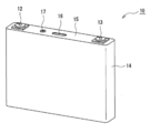
- FIG. 1 is a perspective view showing the appearance of the secondary battery 10 which is an example of the embodiment
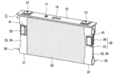
- FIG. 2 is a perspective view of the electrode body 11 and the sealing plate 15 constituting the secondary battery 10.
- the secondary battery 10 illustrated in FIG. 1 is a square battery including a square outer can 14, but the outer body of the battery is not limited to the outer can 14, and is composed of, for example, a laminated sheet including a metal layer and a resin layer. It may be a wrapping body or a cylindrical outer can.
- the secondary battery 10 includes an electrode body 11, an electrolyte, and a square outer can 14 for accommodating them.
- the outer can 14 is a flat, substantially rectangular parallelepiped-shaped metal container having an opening.
- the electrode body 11 is a wound electrode body in which a positive electrode 20 and a negative electrode 30 are spirally wound via a separator 32 and formed into a flat shape.
- the positive electrode 20, the negative electrode 30, and the separator 32 are all strip-shaped elongated bodies.
- the secondary battery 10 has a positive electrode current collector 25 connected to the positive electrode 20 and a negative electrode current collector 35 connected to the negative electrode 30.
- the electrode body may be a laminated electrode body in which a plurality of positive electrodes and a plurality of negative electrodes are alternately laminated one by one via a separator 32.
- the electrolyte may be an aqueous electrolyte or a non-aqueous electrolyte.
- a non-aqueous electrolyte is used.
- the non-aqueous electrolyte contains a non-aqueous solvent and an electrolyte salt dissolved in the non-aqueous solvent.
- the non-aqueous solvent for example, esters, ethers, nitriles, amides, and a mixed solvent of two or more of these may be used.
- the non-aqueous solvent may contain a halogen substituent in which at least a part of hydrogen in these solvents is substituted with a halogen atom such as fluorine.
- the electrolyte salt for example, a lithium salt such as LiPF 6 is used.
- the electrolyte is not limited to the liquid electrolyte, and may be a solid electrolyte using a gel polymer or the like.
- the secondary battery 10 has a positive electrode terminal 12 that is electrically connected to the positive electrode 20 via the positive electrode current collector 25 and a negative electrode terminal 13 that is electrically connected to the negative electrode 30 via the negative electrode current collector 35. Be prepared. Further, the secondary battery 10 includes a sealing plate 15 that closes the opening of the outer can 14.
- the outer can 14 and the sealing plate 15 are made of, for example, a metal material containing aluminum as a main component.
- the sealing plate 15 has an elongated rectangular shape, and the positive electrode terminal 12 is arranged on one end side in the longitudinal direction of the sealing plate 15 and the negative electrode terminal 13 is arranged on the other end side.
- the positive electrode terminal 12 and the negative electrode terminal 13 are external connection terminals connected to another secondary battery 10 or a load, and are fixed to the sealing plate 15 via an insulating member.
- the sealing plate 15 is generally provided with a gas discharge valve 16 and an electrolytic solution injection unit 17.
- the electrode body 11 includes a flat portion and a pair of curved portions.
- the winding axis direction is along the lateral direction of the outer can 14 (the direction in which the positive electrode terminal 12 and the negative electrode terminal 13 are lined up), and the width direction of the electrode body 11 in which the pair of curved portions are lined up is the height of the secondary battery 10. It is housed in the outer can 14 in a state along the vertical direction (the direction orthogonal to the lateral direction and the thickness direction of the outer can 14).
- a core laminated portion 24 of the positive electrode 20 is formed at one end in the axial direction of the electrode body 11, and a core laminated portion 34 of the negative electrode 30 is formed at the other end in the axial direction.
- the body stacking portion is electrically connected to the external connection terminal via the current collector.
- An insulating electrode body holder may be arranged between the electrode body 11 and the inner surface of the outer can 14.
- the positive electrode 20 includes a positive electrode core body 21 and a positive electrode mixture layer (not shown) formed on the surface of the positive electrode core body 21 leaving an exposed region 23 where the surface of the positive electrode core body 21 is exposed.
- a metal foil that is stable in the potential range of the positive electrode 20 such as aluminum in the battery operating voltage range, a film in which the metal is arranged on the surface layer, or the like can be used.
- the positive electrode mixture layer contains a positive electrode active material such as a lithium transition metal compound, a conductive material such as acetylene black, and a binder material such as polyvinylidene fluoride.
- the positive electrode mixture layer is formed on both sides of the positive electrode core body 21.
- the positive electrode 20 is provided with an exposed region 23 in which the positive electrode mixture layer is not formed and the surface of the positive electrode core 21 is exposed.
- the exposed region 23 is formed in a band shape along the longitudinal direction of the positive electrode 20 at one end in the width direction of the positive electrode 20. Further, the exposed region 23 is formed on both surfaces of the positive electrode 20 with a substantially constant width from one end in the width direction of the positive electrode 20.
- the positive electrode 20 is wound so that the exposed region 23 is arranged at one end in the axial direction of the electrode body 11 and the exposed regions 23 overlap each other without passing through the separator 32 or the like.
- the negative electrode 30 includes a negative electrode core 31 and a negative electrode mixture layer (not shown) formed on the surface of the negative electrode core 31 leaving an exposed region 33 where the surface of the negative electrode core 31 is exposed.
- the negative electrode mixture layer contains a negative electrode active material such as graphite and a Si-containing compound, and a binder such as styrene-butadiene rubber (SBR).
- SBR styrene-butadiene rubber
- the negative electrode mixture layer is formed on both sides of the negative electrode core body 31.
- the thickness of the negative electrode core 31 is, for example, 5 ⁇ m to 10 ⁇ m, preferably 8 ⁇ m or less (5 ⁇ m or more).
- the negative electrode core 31 is composed of a copper foil having a surface roughness of 2.0 ⁇ m or less and a glossiness of 50 to 350.
- the copper foil contains Cu as a main component and may contain a small amount of a metal element other than Cu such as Cr.
- the negative electrode core 31 may be made of a material containing a copper foil having a surface roughness of 2.0 ⁇ m or less and a glossiness of 50 to 350.
- the surface roughness of the negative electrode core 31 is preferably 0 ⁇ m or more and 2.0 ⁇ m or less on both sides.
- a preferable example of the surface roughness of the negative electrode core body 31 is 0 ⁇ m or more and 1.60 ⁇ m or less, which has less surface irregularities.
- the surface roughness is measured by a non-contact method using a surface roughness measuring machine (manufactured by Kosaka, SE1700 ⁇ ) according to the measuring method specified in JIS B 0601 1994.
- the glossiness of the negative electrode core 31 is preferably 50 to 350 on both sides.
- a preferable example of the glossiness of the negative electrode core body 31 is 50 to 96.
- the glossiness is measured at an incident angle of 60 ° using a surface gloss measuring device (Micro-gloss manufactured by BYK) according to a measuring method defined in JIS (Z8741).
- the negative electrode 30 is provided with an exposed region 33 in which the negative electrode mixture layer is not formed and the surface of the negative electrode core 31 is exposed.
- the exposed region 33 is formed in a band shape along the longitudinal direction of the negative electrode 30 at one end in the width direction of the negative electrode 30. Further, the exposed region 33 is formed on both surfaces of the negative electrode 30 with a substantially constant width from one end in the width direction of the negative electrode 30.
- the width of the exposed region 33 is, for example, 12 mm or more.
- the negative electrode 30 is wound so that the exposed region 33 is arranged at the other end in the axial direction of the electrode body 11 and the exposed regions 33 overlap each other without passing through the separator 32 or the like.
- the electrode body 11 has a core body laminated portion 24 formed by overlapping the exposed regions 23 of the positive electrode 20 in a plurality of layers, and a core body laminated portion 34 formed by overlapping the exposed regions 33 of the negative electrode 30 in a plurality of layers.
- the exposed region 23 of the positive electrode 20 is formed at one end in the axial direction of the electrode body 11, and the exposed region 33 of the negative electrode 30 is formed at the other end of the electrode body 11 in the axial direction.
- the positive electrode 20 and the negative electrode 30 are arranged so that the positive electrode mixture layer and the negative electrode mixture layer face each other via the separator 32, but the exposed region 23 of the positive electrode 20 does not face the negative electrode 30 and the negative electrode 30
- the positive and negative electrodes are arranged so as to be offset in the axial direction of the electrode body 11 so that the exposed region 33 does not face the positive electrode 20.
- the core body laminated portions 24 and 34 are formed by laminating 40 or more layers of the positive electrode core body 21 and the negative electrode core body 31, respectively.
- the number of layers of the core body in the core body laminated portions 24 and 34 depends on the number of turns of the positive electrode 20 and the negative electrode 30, and the number of layers increases as the number of turns increases. By increasing the number of turns of the positive electrode 20 and the negative electrode 30, it is possible to increase the capacity and output of the secondary battery 10.
- welding defects occur such that voids are likely to occur at the interface with the current collector due to the influence of variations in the surface state of the core. It will be easier. In particular, welding of the core laminated portion 34 made of copper foil and the negative electrode current collector 35 becomes a problem.
- the welded portion between the core body laminated portion and the current collector will be described by taking the negative electrode 30 as an example.
- the same configuration as in the case of the negative electrode 30 described below can be applied to the welded portion between the core laminated portion 24 of the positive electrode 20 and the positive electrode current collector 25.
- a conventionally known configuration may be applied to the welded portion between the core body laminated portion 24 and the positive electrode current collector 25.
- the negative electrode current collector 35 is composed of, for example, a metal containing copper as a main component.
- the negative electrode current collector 35 preferably includes a first member 36 and a second member 37.
- the core body laminated portion 34 is welded to the first member 36 and the second member 37 in a state of being sandwiched between the first member 36 and the second member 37 from both sides in the thickness direction of the electrode body 11.
- the core body laminated portion 34 is compressed in the thickness direction of the electrode body 11, and the overlapping exposed regions 33 are in contact with each other.
- the first member 36 constituting the negative electrode current collector 35 is welded to one surface of the core body laminated portion 34, extends to the sealing plate 15 side, and is connected to the negative electrode terminal 13.
- the second member 37 is a substantially rectangular plate-shaped member, and the end portion may be bent to the opposite side to the core body laminated portion 34 from the viewpoint of preventing spatter generated during welding.
- the second member 37 is welded to the other surface of the core body laminated portion 34 and is not connected to other members. Therefore, the member having a current collecting function for electrically connecting the negative electrode terminal 13 and the negative electrode 30 is the first member 36. It can be said that the second member 37 is a receiving member for sandwiching the core body laminated portion 34 together with the first member 36 to ensure good weldability between the core body laminated portion 34 and the negative electrode current collector 35.
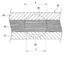
- FIG. 3 is a cross-sectional view of the welded portion of the core body laminated portion 34 and the negative electrode current collector 35 and its vicinity.
- a nugget 40 is formed by welding in the welded portion between the core body laminated portion 34 and the negative electrode current collector 35.
- the nugget 40 means a region in which the negative electrode core 31 and the negative electrode current collector 35 forming the core laminated portion 34 are melted into a lump.
- a large nugget 40 is formed in the welded portion between the core body laminated portion 34 and the negative electrode current collector 35, and the maximum diameter (X) thereof is preferably 1.6 mm or more.
- the nugget 40 is formed, for example, in a spherical shape centered on the central portion in the thickness direction of the core body laminated portion 34, but the diameter thereof generally varies to some extent.
- the maximum diameter (X) of the nugget 40 means the maximum delivery diameter of the nugget 40.
- the core body laminated portion 34 includes a nugget 40 formed by welding with each member in a state of being sandwiched between the first member 36 and the second member 37 from both sides.
- the contact length (Y) of the nugget 40 of the core body laminated portion 34 and the first member 36 and the second member 37 is preferably 1.0 mm or more, respectively.
- the length (maximum transfer length) exceeds 1.0 mm at the interface between the core body laminated portion 34 and the negative electrode current collector 35 (first member 36 and second member 37), as illustrated in FIG. 7 described later. There are no voids, and the core laminated portion 34 and the negative electrode current collector 35 are strongly bonded. Therefore, the welded portion between the core body laminated portion 34 and the negative electrode current collector 35 has high strength and low resistance.
- the ratio (Y / X) of the contact length (Y) between the nugget 40 and the negative electrode current collector 35 with respect to the maximum diameter (X) of the nugget 40 is preferably 40% or more, more preferably 50% or more, and 60%. % Or more is particularly preferable.
- the maximum diameter (X) of the nugget 40 is the same, for example, as the voids existing at the interface between the core body laminated portion 34 and the negative electrode current collector 35 decrease, the contact length (Y) becomes longer and Y / X. Is a high value.
- an insulation having a hole 42 having a diameter of 4.1 mm to 4.3 mm is provided between the core laminated portion 34 and the negative electrode current collector 35. It is preferable that the sheet 41 is arranged. With such a diameter, it is possible to prevent the insulating sheet from melting during resistance welding.
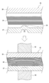
- FIG. 4 is a diagram showing a welding process between the core body laminated portion 34 and the negative electrode current collector 35
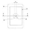
- FIGS. 5 and 6 are second members 37 constituting the negative electrode current collector 35 before being welded to the core body laminated portion 34. It is a figure which shows.
- the core body laminated portion 34 and the negative electrode current collector 35 are resistance welded using a pair of electrode rods 50.
- the manufacturing process of the secondary battery 10 includes the following steps. (1) A step of forming a projection 38 on at least one of a first member 36 and a second member 37 constituting the negative electrode current collector 35. (2) The core body laminated portion 34 and the negative electrode current collector 35 are sandwiched between the first member 36 and the second member 37 from both sides and the projection 38 is in contact with the core body laminated portion 34. The process of resistance welding.
- the manufacturing process of the secondary battery 10 includes a step of manufacturing a positive electrode 20, a step of manufacturing a negative electrode 30, a step of manufacturing an electrode body 11, a step of welding a current collector and an external connection terminal, and a secondary battery.
- the step of assembling each member constituting 10 is included.
- the negative electrode 30 is a negative electrode mixture slurry containing a negative electrode active material, a binder, and the like, leaving a strip-shaped exposed region 33 along the longitudinal direction on both sides of a negative electrode core 31 made of, for example, a long copper foil. It can be produced by coating, drying the coating film, and then rolling to form a negative electrode mixture layer on both sides of the negative electrode core 31.
- the positive electrode 20 can also be produced by using a mixture slurry in the same manner as the negative electrode 30.
- the electrode body 11 is produced by winding the positive electrode 20 and the negative electrode 30 in a spiral shape via a separator 32 so that the core body laminated portions 24 and 34 are formed, and then press-molding the electrode body 11 into a flat shape. .. It is also possible to manufacture the electrode body 11 by winding the positive electrode 20 and the negative electrode 30 in a flat shape.
- the separator 32 is provided so that the exposed regions 23 and 33 are located on opposite sides of each other, the exposed region 23 does not overlap the negative electrode 30 and the separator 32, and the exposed region 33 does not overlap the positive electrode 20 and the separator 32.
- the positive electrode 20 and the negative electrode 30 are overlapped with each other and wound using a predetermined winding core to prepare the electrode body 11.
- the projection 38 is formed on the second member 37 constituting the negative electrode current collector 35.
- the projection 38 is a protrusion that abuts on the core body laminated portion 34, and protrudes toward the core body laminated portion 34 side.
- the projection 38 may be formed only on the first member 36, or may be formed on both the first member 36 and the second member 37.
- the surface of the negative electrode current collector 35 (the first member 36 and the second member 37) that abuts on the core laminated portion 34 (hereinafter, may be referred to as a “contact surface”) excludes a portion where the projection 38 is formed. It is almost flat.
- the thickness of the first member 36 is 0.95 mm to 1.05 mm
- the thickness of the second member 37 is 0.77 mm to 0.83 mm.
- the thickness of the second member 37 on which the projection 38 is formed is set to the thickness at which the projection 38 is not formed. It is preferable that the thickness of one member 36 is smaller than that of the member 36.
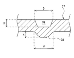
- a projection 38 having a height (h) of 0.36 mm to 0.45 mm is formed on the contact surface of the second member 37.
- the height (h) of the projection 38 is preferably 0.37 mm to 0.44 mm, more preferably 0.38 mm to 0.43 mm, and particularly preferably 0.39 mm to 0.42 mm.
- the height (h) of the projection 38 means the length from the flat region of the contact surface of the negative electrode current collector 35 to the tip of the projection 38 along the thickness direction of the negative electrode current collector 35.
- the contact surface of the second member 37 is flat except for the region where the projection 38 is formed. If the height of the projection 38 exceeds 0.45 mm, the electrode body 11 may be tilted by the pressurization before resistance welding, and the contact resistance between the projection 38 and the core body laminated portion 34 may vary. To do.
- the projection 38 may be formed in a substantially trapezoidal shape with a flat tip, for example, but is preferably formed in a circular hill shape.
- the diameter (d) of the circular hill-shaped projection 38 is preferably controlled to 1.41 mm to 1.49 mm. By controlling the diameter (d) within the range, the generation of voids is suppressed and a clean nugget 40 is formed as compared with the case where the diameter (d) is outside the range.
- a plurality of projections 38 may be formed on the contact surface of the second member 37, but one is preferably formed on the second member 37 from the viewpoint of current concentration during resistance welding.
- the projection 38 may be formed one by one on the contact surface of the first member 36 and the second member 37.
- the projection 38 may be formed on any of the contact surfaces of the second member 37 as long as it satisfies the above dimensions and does not interfere with the welding operation. However, when one projection 38 is formed on each of the first member 36 and the second member 37, the projections 38 are formed so as to face each other with the core body laminated portion 34 interposed therebetween.
- the projection 38 is formed by, for example, pressing the second member 37 from the surface opposite to the contact surface. Therefore, the second member 37 is formed with a recess 39 on the surface opposite to the projection 38 (contact surface) at a position where the projection 38 and the second member 37 overlap in the thickness direction.
- the projection 38 is melted and crushed, but the shape of the recess 39 remains, so the shape and dimensions of the recess 39, the thickness of the second member 37, etc. From this, the shape, dimensions, etc. of the projection 38 can be estimated.
- the diameter (D) of the recess 39 is, for example, 1.10 mm to 1.30 mm, preferably 1.15 mm to 1.25 mm. As illustrated in FIG. 6, the recess 39 is formed in a substantially trapezoidal cross-sectional view whose diameter decreases toward the projection 38 side. In this case, the diameter (D) means the maximum diameter at the entrance of the recess 39.
- the depth (H) of the recess 39 is, for example, 0.40 mm to 0.60 mm, preferably 0.45 mm to 0.55 mm.
- the core body laminated portion 34 is sandwiched between the first member 36 and the second member 37, and the projection 38 is pressed against the core body laminated portion 34, and the core body is laminated.
- the portion 34 and the negative electrode current collector 35 are resistance welded.
- the insulating sheet 41 is arranged between the core body laminated portion 34 and the first member 36, and the insulating sheet 41 is arranged between the core body laminated portion 34 and the second member 37.
- each member is melted by passing an electric current to generate Joule heat while pressurizing the core body laminated portion 34 and the negative electrode current collector 35 from both sides in the thickness direction using a pair of electrode rods 50. Form the nugget 40.
- the resistance welding may be performed in a state where an insulating sheet 41 (see FIG. 5) having a hole 42 having a diameter of 4.1 mm to 4.3 mm is arranged between the core body laminated portion 34 and the negative electrode current collector 35.
- an insulating sheet 41 see FIG. 5
- the core body laminated portion 34 and the negative electrode current collector 35 are resistance welded through the holes 42 of the insulating sheet 41.
- Example 1 [Cathode preparation] A positive electrode mixture slurry was applied to both sides of a positive electrode core made of an aluminum foil having a width of 127 mm (coating width 108 mm) to form a coating film, dried, and the coating film was compressed. A positive electrode core body on which a coating film (positive electrode mixture layer) was formed was cut to a predetermined electrode size to prepare a positive electrode. The positive electrode mixture slurry is not applied to the positive electrode, and the exposed region where the surface of the core is exposed is formed in a strip shape with a constant width along the longitudinal direction of the positive electrode.
- a negative electrode mixture slurry was applied to both sides of a negative electrode core having a width of 130 mm and a thickness of 8 ⁇ m (coating width 117 mm) to form a coating film, dried, and the coating film was compressed.
- a negative electrode core body on which a coating film (negative electrode mixture layer) was formed was cut to a predetermined electrode size to prepare a negative electrode.
- a copper foil having a surface roughness of 1.9 ⁇ m and a glossiness of 340 was used as the negative electrode core.
- the negative electrode mixture slurry is not applied to the negative electrode, and the exposed region where the surface of the core is exposed is formed in a strip shape with a constant width (13 mm) along the longitudinal direction of the negative electrode.
- the prepared positive electrode and negative electrode are overlapped with each other via a separator having a width of 119 mm so that their exposed regions are located on opposite sides in the width direction of the electrode, and separator A / negative electrode / separator B / positive electrode / in the radial direction of the wound body.
- the wound body is pressed in the radial direction (temperature 25 ° C., press pressure 85 kN, press time 5 s) to have a thickness of 15.7 mm (press time 5 s).
- a flat, wound-type electrode body (average thickness when 30 pieces were produced) was produced.
- a positive electrode core laminated portion in which a positive electrode core exposed region is laminated is formed at one end in the axial direction of the electrode body, and a negative electrode core in which a negative electrode core exposed region is laminated is formed at the other end in the axial direction.
- a laminated portion is formed.
- the number of laminated negative electrode cores in the laminated negative electrode core was 84 layers.
- the first member constituting the negative electrode current collector is caulked and fixed to the sealing body and connected to the negative electrode terminal, and the negative electrode core body laminated portion is formed by the first member and the second member of the negative electrode current collector. It is compressed and the laminated part and the negative electrode current collector are resistance welded.
- the first member and the second member are copper members, and the thickness of the first member is 1.0 mm and the thickness of the second member is 0.8 mm.
- the second member of the negative electrode current collector was press-processed to form a circular hill-shaped projection having a height (h) of 0.41 mm and a diameter (d) of 1.45 mm.
- a recess having a diameter (D) of 1.20 mm and a depth (H) of 0.5 mm was formed on the surface opposite to the contact surface that abuts the core body laminated portion of the second member.
- an insulating sheet having a thickness of 0.1 mm in which a hole having a diameter of 4.2 mm was formed was arranged between the negative electrode core body laminated portion and the first member and the second member. At this time, the insulating sheets were arranged so that the holes of the two insulating sheets overlapped in the thickness direction of the core laminated portion and the projection of the second member was located at the center of the holes.
- a pair of electrode rods are attached to the first member and the second member.
- Resistance welding was performed by applying a current in a two-stage energization method in a state where the laminated portion was pressed against the surface and compressed (pressurizing pressure 1600 N).
- the energization time of the first energization was 2.3 ms, and the energization time of the second energization was 3 ms.
- peeling strength As a result of measuring the strength (peeling strength) of the welded portion using an autograph manufactured by Shimadzu Corporation, the peeling strength was 626N. Further, as a result of measuring the negative electrode resistance using a resistance measuring device manufactured by Hioki Electric, the resistance value was 0.0056 m ⁇ .
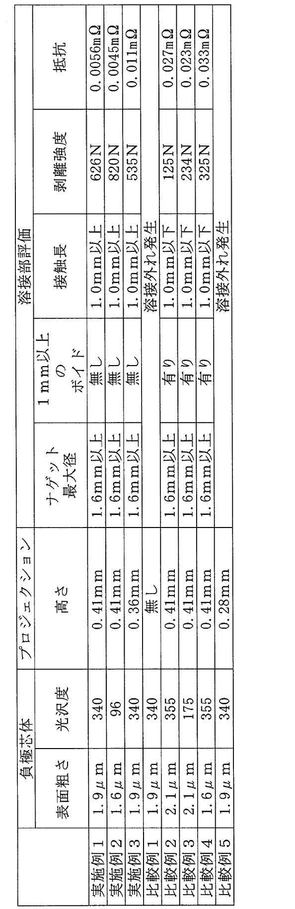
- the following Examples and Comparative Examples were also evaluated in the same manner as in Example 1. The evaluation results are shown in Table 1.
- Example 2 An electrode body was produced in the same manner as in Example 1 except that a copper foil having a surface roughness of 1.6 ⁇ m and a glossiness of 96 was used as the negative electrode core body, and the negative electrode core body laminated portion and the negative electrode current collection were performed. The body was resistance welded and the welded part was evaluated.
- Example 3 An electrode body was produced by the same method as in Example 1 except that the height (h) of the projection formed on the second member of the negative electrode current collector was 0.36 mm and the diameter (d) was 1.19 mm. , The negative electrode core laminated portion and the negative electrode current collector were resistance welded to evaluate the welded portion.
- the electrode body was produced by the same method as in Example 1 except that the projection was not formed on the second member of the negative electrode current collector, and the negative electrode core body laminated portion and the negative electrode current collector were resistance welded to the welded portion. Was evaluated.
- Example 2 An electrode body was produced in the same manner as in Example 1 except that a copper foil having a surface roughness of 2.1 ⁇ m and a glossiness of 355 was used as the negative electrode core body, and the negative electrode core body laminated portion and the negative electrode current collection were performed. The body was resistance welded and the welded part was evaluated.
- Example 3 An electrode body was produced in the same manner as in Example 1 except that a copper foil having a surface roughness of 2.1 ⁇ m and a glossiness of 175 was used as the negative electrode core body, and the negative electrode core body laminated portion and the negative electrode current collection were performed. The body was resistance welded and the welded part was evaluated.
- Example 4 An electrode body was produced in the same manner as in Example 1 except that a copper foil having a surface roughness of 1.6 ⁇ m and a glossiness of 355 was used as the negative electrode core body, and the negative electrode core body laminated portion and the negative electrode current collection were performed. The body was resistance welded and the welded part was evaluated.
- Example 2 As shown in Table 1, in the examples, the generation of voids in the welded portion between the negative electrode core body laminated portion and the negative electrode current collector was significantly suppressed, and a welded portion having high peel strength and low resistance was obtained. In particular, in Example 2, no voids were found in the welded portion, and a clean nugget was formed.
- Electrode body 12 Positive electrode terminal 13 Negative electrode terminal 14 Exterior can 15 Seal plate 16 Gas discharge valve 17 Electrolyte injection part 20 Positive electrode 21 Positive electrode core body 23,33 Exposed area 24,34 Core body laminated part 25 Positive electrode current collection Body 30 Negative electrode 31 Negative core body 32 Separator 35 Negative electrode current collector 36 First member 37 Second member 38 Projection 39 Recess 40 Nugget 41 Insulation sheet 42 Hole 50 Electrode rod
Landscapes
- Chemical & Material Sciences (AREA)
- Chemical Kinetics & Catalysis (AREA)
- Electrochemistry (AREA)
- General Chemical & Material Sciences (AREA)
- Engineering & Computer Science (AREA)
- Manufacturing & Machinery (AREA)
- Materials Engineering (AREA)
- Mechanical Engineering (AREA)
- Cell Electrode Carriers And Collectors (AREA)
- Secondary Cells (AREA)
- Connection Of Batteries Or Terminals (AREA)
Abstract
Description
(1)負極集電体35を構成する第1部材36及び第2部材37の少なくとも一方にプロジェクション38を形成する工程。
(2)芯体積層部34が第1部材36及び第2部材37によって両側から挟まれ、プロジェクション38が芯体積層部34に当接した状態で、芯体積層部34と負極集電体35を抵抗溶接する工程。
[正極の作製]
正極合材スラリーを幅127mmのアルミニウム箔からなる正極芯体の両面に塗布(塗布幅108mm)して塗膜を形成、乾燥し、塗膜を圧縮した。塗膜(正極合材層)が形成された正極芯体を所定の電極サイズに切断して、正極を作製した。正極には、正極合材スラリーが塗布されず、芯体表面が露出した露出領域が正極の長手方向に沿って一定の幅で帯状に形成されている。
負極合材スラリーを幅130mm、厚み8μmの負極芯体の両面に塗布(塗布幅117mm)して塗膜を形成、乾燥し、塗膜を圧縮した。塗膜(負極合材層)が形成された負極芯体を所定の電極サイズに切断して、負極を作製した。実施例1では、負極芯体として、表面粗さが1.9μm、光沢度が340の銅箔を用いた。負極には、負極合材スラリーが塗布されず、芯体表面が露出した露出領域が負極の長手方向に沿って一定の幅(13mm)で帯状に形成されている。
作製した正極及び負極を、各々の露出領域が電極の幅方向反対側に位置するように幅119mmのセパレータを介して重ね合わせ、巻回体の径方向にセパレータA/負極/セパレータB/正極/セパレータA・・・の順で積層されるように渦巻き状に巻回した後、巻回体の径方向にプレス(温度25℃、プレス圧85kN、プレス時間5s)して、厚み15.7mm(30個作製したときの平均厚み)の扁平状の巻回型電極体を作製した。電極体の軸方向一端部には、正極の芯体露出領域が積層された正極芯体積層部が形成され、軸方向他端部には、負極の芯体露出領域が積層された負極芯体積層部が形成される。負極芯体積層部における負極芯体の積層数は84層であった。
次に、負極集電体を構成する第1部材を封口体にかしめ固定して負極端子と接続し、当該第1部材と、負極集電体の第2部材とで、負極芯体積層部を圧縮し、積層部と負極集電体を抵抗溶接する。第1部材及び第2部材は銅製の部材であって、第1部材の厚みは1.0mm、第2部材の厚み0.8mmである。実施例1では、負極集電体の第2部材をプレス加工して、高さ(h)が0.41mm、直径(d)が1.45mmの円丘状のプロジェクションを形成した。第2部材の芯体積層部に当接する当接面と反対側の面には、直径(D)が1.20mm、深さ(H)が0.5mmの凹部が形成された。
下記の手順で負極芯体積層部と負極集電体の溶接部を評価した。
・ ニッパーを使って溶接部の近傍を切り取る。
・ 切り取ったサンプル片をエポキシ樹脂で固める。
・ ナゲットの中心部までエポキシ樹脂で固めたサンプル片を削る。
・ ナゲットが観察し易いように不要物をエッチング除去する。
・ 処理したサンプル片を光学顕微鏡で観察する。
負極芯体として、表面粗さが1.6μm、光沢度が96の銅箔を用いたこと以外は、実施例1と同様の方法で電極体を作製し、負極芯体積層部と負極集電体を抵抗溶接して溶接部の評価を行った。
負極集電体の第2部材に形成するプロジェクションの高さ(h)を0.36mm、直径(d)を1.19mmとしたこと以外は、実施例1と同様の方法で電極体を作製し、負極芯体積層部と負極集電体を抵抗溶接して溶接部の評価を行った。
負極集電体の第2部材にプロジェクションを形成しなかったこと以外は、実施例1と同様の方法で電極体を作製し、負極芯体積層部と負極集電体を抵抗溶接して溶接部の評価を行った。
負極芯体として、表面粗さが2.1μm、光沢度が355の銅箔を用いたこと以外は、実施例1と同様の方法で電極体を作製し、負極芯体積層部と負極集電体を抵抗溶接して溶接部の評価を行った。
負極芯体として、表面粗さが2.1μm、光沢度が175の銅箔を用いたこと以外は、実施例1と同様の方法で電極体を作製し、負極芯体積層部と負極集電体を抵抗溶接して溶接部の評価を行った。
負極芯体として、表面粗さが1.6μm、光沢度が355の銅箔を用いたこと以外は、実施例1と同様の方法で電極体を作製し、負極芯体積層部と負極集電体を抵抗溶接して溶接部の評価を行った。
負極集電体の第2部材に形成するプロジェクションの高さ(h)を0.28mm、直径(d)を1.11mmとしたこと以外は、実施例1と同様の方法で電極体を作製し、負極芯体積層部と負極集電体を抵抗溶接して溶接部の評価を行った。
11 電極体
12 正極端子
13 負極端子
14 外装缶
15 封口板
16 ガス排出弁
17 電解液注入部
20 正極
21 正極芯体
23,33 露出領域
24,34 芯体積層部
25 正極集電体
30 負極
31 負極芯体
32 セパレータ
35 負極集電体
36 第1部材
37 第2部材
38 プロジェクション
39 凹部
40 ナゲット
41 絶縁シート
42 孔
50 電極棒
Claims (7)
- 正極と、負極と、セパレータとを有し、前記正極と前記負極とが前記セパレータを介して積層されてなる電極体と、負極集電体とを備える二次電池の製造方法であって、
前記負極は、表面粗さが0μm以上2.0μm以下であり、光沢度が50以上350以下の銅箔で構成される負極芯体と、前記負極芯体の表面が露出する露出領域を残して前記負極芯体の表面に形成される負極合材層とを含み、
前記電極体は、前記負極の前記露出領域が積層されてなる芯体積層部を有し、
前記負極集電体は、構成する第1部材及び第2部材の少なくとも一方に、高さが0.36mm以上0.45mm以下のプロジェクションを有し、
前記第1部材及び前記第2部材によって前記芯体積層部が両側から挟まれ、前記プロジェクションが前記芯体積層部に当接した状態で、前記負極集電体と前記芯体積層部を抵抗溶接する工程を含む、二次電池の製造方法。 - 前記芯体積層部は、前記負極芯体を40層以上積層して形成される、請求項1に記載の二次電池の製造方法。
- 前記プロジェクションは、直径が1.41mm以上1.49mm以下の円丘状に形成される、請求項1または2に記載の二次電池の製造方法。
- 前記第1部材及び前記第2部材の少なくとも一方には、前記プロジェクションと重なる位置において前記プロジェクションが形成された面と反対側の面に、直径が1.10mm以上1.30mm以下の凹部が形成される、請求項1~3のいずれか1項に記載の二次電池の製造方法。
- 前記芯体積層部と前記負極集電体の間に、直径が4.1mm以上4.3mm以下の孔を有する絶縁シートを配置し、
前記絶縁シートの孔を介して前記芯体積層部と前記負極集電体を抵抗溶接する、請求項1~4のいずれか1項に記載の二次電池の製造方法。 - 正極と、負極と、セパレータとを有し、前記正極と前記負極とが前記セパレータを介して積層された電極体と、負極集電体とを備える二次電池であって、
前記負極は、表面粗さが2.0μm以下であり、光沢度が50以上350以下の銅箔で構成される負極芯体と、前記負極芯体の表面が露出する露出領域を残して前記負極芯体の表面に形成された負極合材層とを含み、
前記電極体は、前記負極の前記露出領域が積層された芯体積層部を有し、
前記芯体積層部は、前記負極集電体を構成する第1部材及び第2部材によって両側から挟まれた状態で当該各部材と溶接され、溶接により形成されたナゲットを含み、
前記芯体積層部と前記負極集電体の界面には長さが1.0mmを超えるボイドが存在せず、前記ナゲットの最大径が1.6mm以上である、二次電池。 - 前記ナゲットの最大径に対する、前記負極集電体と前記ナゲットの接触長の割合が40%以上である、請求項6に記載の二次電池。
Priority Applications (5)
| Application Number | Priority Date | Filing Date | Title |
|---|---|---|---|
| EP20871107.7A EP4040545B1 (en) | 2019-09-30 | 2020-07-01 | Method for producing secondary battery, and secondary battery |
| CN202080058692.9A CN114258597B (zh) | 2019-09-30 | 2020-07-01 | 二次电池的制造方法、以及二次电池 |
| JP2021550339A JP7470130B2 (ja) | 2019-09-30 | 2020-07-01 | 二次電池の製造方法、及び二次電池 |
| US17/635,887 US20220294087A1 (en) | 2019-09-30 | 2020-07-01 | Method for producing secondary battery, and secondary battery |
| US19/263,254 US20250337132A1 (en) | 2019-09-30 | 2025-07-08 | Method for producing secondary battery, and secondary battery |
Applications Claiming Priority (2)
| Application Number | Priority Date | Filing Date | Title |
|---|---|---|---|
| JP2019-179957 | 2019-09-30 | ||
| JP2019179957 | 2019-09-30 |
Related Child Applications (2)
| Application Number | Title | Priority Date | Filing Date |
|---|---|---|---|
| US17/635,887 A-371-Of-International US20220294087A1 (en) | 2019-09-30 | 2020-07-01 | Method for producing secondary battery, and secondary battery |
| US19/263,254 Division US20250337132A1 (en) | 2019-09-30 | 2025-07-08 | Method for producing secondary battery, and secondary battery |
Publications (1)
| Publication Number | Publication Date |
|---|---|
| WO2021065127A1 true WO2021065127A1 (ja) | 2021-04-08 |
Family
ID=75337979
Family Applications (1)
| Application Number | Title | Priority Date | Filing Date |
|---|---|---|---|
| PCT/JP2020/025842 Ceased WO2021065127A1 (ja) | 2019-09-30 | 2020-07-01 | 二次電池の製造方法、及び二次電池 |
Country Status (5)
| Country | Link |
|---|---|
| US (2) | US20220294087A1 (ja) |
| EP (1) | EP4040545B1 (ja) |
| JP (1) | JP7470130B2 (ja) |
| CN (1) | CN114258597B (ja) |
| WO (1) | WO2021065127A1 (ja) |
Cited By (1)
| Publication number | Priority date | Publication date | Assignee | Title |
|---|---|---|---|---|
| JP2024011563A (ja) * | 2022-07-15 | 2024-01-25 | プライムプラネットエナジー&ソリューションズ株式会社 | 電池用導電部材とその製造方法 |
Families Citing this family (2)
| Publication number | Priority date | Publication date | Assignee | Title |
|---|---|---|---|---|
| CN219534591U (zh) * | 2023-03-16 | 2023-08-15 | 欣旺达电动汽车电池有限公司 | 一种单体电池及一种电池包 |
| CN220984564U (zh) * | 2023-09-19 | 2024-05-17 | 中创新航科技集团股份有限公司 | 一种电池以及电池包 |
Citations (8)
| Publication number | Priority date | Publication date | Assignee | Title |
|---|---|---|---|---|
| JP2005259511A (ja) * | 2004-03-11 | 2005-09-22 | Sanyo Electric Co Ltd | 電池 |
| JP2009032640A (ja) | 2007-06-27 | 2009-02-12 | Sanyo Electric Co Ltd | 密閉電池及びその製造方法 |
| JP2012099351A (ja) | 2010-11-02 | 2012-05-24 | Jx Nippon Mining & Metals Corp | リチウムイオン電池集電体用銅箔 |
| JP2013196959A (ja) * | 2012-03-21 | 2013-09-30 | Toyota Industries Corp | 蓄電装置及び二次電池並びに車両 |
| JP2014120399A (ja) | 2012-12-18 | 2014-06-30 | Toshiba Corp | 電極、電池および電池パック |
| JP2015039713A (ja) * | 2013-08-22 | 2015-03-02 | 日本アビオニクス株式会社 | 溶接装置 |
| JP5917407B2 (ja) * | 2010-10-29 | 2016-05-11 | 三洋電機株式会社 | 角形二次電池 |
| JP2018174075A (ja) | 2017-03-31 | 2018-11-08 | Jx金属株式会社 | リチウムイオン電池集電体用圧延銅箔及びリチウムイオン電池 |
Family Cites Families (9)
| Publication number | Priority date | Publication date | Assignee | Title |
|---|---|---|---|---|
| JP2000200594A (ja) | 1999-01-05 | 2000-07-18 | Japan Storage Battery Co Ltd | 電 池 |
| JP4494731B2 (ja) | 2003-06-13 | 2010-06-30 | 三菱重工業株式会社 | 二次電池、二次電池の製造方法 |
| JP2007227328A (ja) * | 2006-01-24 | 2007-09-06 | Sanyo Electric Co Ltd | リチウム二次電池用負極及びその製造方法並びにリチウム二次電池 |
| JP5128695B2 (ja) * | 2010-06-28 | 2013-01-23 | 古河電気工業株式会社 | 電解銅箔、リチウムイオン二次電池用電解銅箔、該電解銅箔を用いたリチウムイオン二次電池用電極、該電極を使用したリチウムイオン二次電池 |
| JP6072676B2 (ja) * | 2011-03-31 | 2017-02-01 | 三洋電機株式会社 | 角形二次電池の製造方法 |
| US20140023913A1 (en) * | 2012-07-17 | 2014-01-23 | Sanyo Electric Co., Ltd. | Prismatic secondary battery |
| JP6878878B2 (ja) * | 2016-12-26 | 2021-06-02 | 三洋電機株式会社 | 二次電池の製造方法および二次電池 |
| JP6768578B2 (ja) * | 2017-03-27 | 2020-10-14 | 三洋電機株式会社 | 角形二次電池の製造方法 |
| JP7013773B2 (ja) * | 2017-09-29 | 2022-02-01 | 三洋電機株式会社 | 非水電解質二次電池及びその製造方法 |
-
2020
- 2020-07-01 CN CN202080058692.9A patent/CN114258597B/zh active Active
- 2020-07-01 EP EP20871107.7A patent/EP4040545B1/en active Active
- 2020-07-01 WO PCT/JP2020/025842 patent/WO2021065127A1/ja not_active Ceased
- 2020-07-01 US US17/635,887 patent/US20220294087A1/en not_active Abandoned
- 2020-07-01 JP JP2021550339A patent/JP7470130B2/ja active Active
-
2025
- 2025-07-08 US US19/263,254 patent/US20250337132A1/en active Pending
Patent Citations (8)
| Publication number | Priority date | Publication date | Assignee | Title |
|---|---|---|---|---|
| JP2005259511A (ja) * | 2004-03-11 | 2005-09-22 | Sanyo Electric Co Ltd | 電池 |
| JP2009032640A (ja) | 2007-06-27 | 2009-02-12 | Sanyo Electric Co Ltd | 密閉電池及びその製造方法 |
| JP5917407B2 (ja) * | 2010-10-29 | 2016-05-11 | 三洋電機株式会社 | 角形二次電池 |
| JP2012099351A (ja) | 2010-11-02 | 2012-05-24 | Jx Nippon Mining & Metals Corp | リチウムイオン電池集電体用銅箔 |
| JP2013196959A (ja) * | 2012-03-21 | 2013-09-30 | Toyota Industries Corp | 蓄電装置及び二次電池並びに車両 |
| JP2014120399A (ja) | 2012-12-18 | 2014-06-30 | Toshiba Corp | 電極、電池および電池パック |
| JP2015039713A (ja) * | 2013-08-22 | 2015-03-02 | 日本アビオニクス株式会社 | 溶接装置 |
| JP2018174075A (ja) | 2017-03-31 | 2018-11-08 | Jx金属株式会社 | リチウムイオン電池集電体用圧延銅箔及びリチウムイオン電池 |
Non-Patent Citations (1)
| Title |
|---|
| See also references of EP4040545A4 |
Cited By (2)
| Publication number | Priority date | Publication date | Assignee | Title |
|---|---|---|---|---|
| JP2024011563A (ja) * | 2022-07-15 | 2024-01-25 | プライムプラネットエナジー&ソリューションズ株式会社 | 電池用導電部材とその製造方法 |
| JP7600178B2 (ja) | 2022-07-15 | 2024-12-16 | プライムプラネットエナジー&ソリューションズ株式会社 | 電池用導電部材とその製造方法 |
Also Published As
| Publication number | Publication date |
|---|---|
| US20220294087A1 (en) | 2022-09-15 |
| JP7470130B2 (ja) | 2024-04-17 |
| CN114258597B (zh) | 2024-06-21 |
| US20250337132A1 (en) | 2025-10-30 |
| EP4040545A4 (en) | 2023-09-13 |
| EP4040545B1 (en) | 2025-09-03 |
| EP4040545A1 (en) | 2022-08-10 |
| CN114258597A (zh) | 2022-03-29 |
| JPWO2021065127A1 (ja) | 2021-04-08 |
Similar Documents
| Publication | Publication Date | Title |
|---|---|---|
| US20250337132A1 (en) | Method for producing secondary battery, and secondary battery | |
| CN112335071B (zh) | 电池用电极、电池以及电池用电极的制造方法 | |
| EP2249416A1 (en) | Lithium-ion secondary battery and manufacturing method thereof | |
| KR20100089092A (ko) | 이차 전지 | |
| JP7545417B2 (ja) | 非水電解質二次電池及びその製造方法 | |
| WO2019069890A1 (ja) | 非水電解質二次電池 | |
| WO2009133652A1 (ja) | 円筒形電池およびその製造方法 | |
| WO2021131878A1 (ja) | 二次電池 | |
| WO2021199684A1 (ja) | 非水電解質二次電池用正極板の製造方法及び非水電解質二次電池の製造方法 | |
| CN108666630B (zh) | 方形二次电池的制造方法 | |
| JP2009259697A (ja) | 電池およびその製造方法 | |
| JP2011216295A (ja) | 円筒型非水電解質二次電池 | |
| JP7394051B2 (ja) | 電池及びその製造方法 | |
| JP7109950B2 (ja) | 非水電解質二次電池 | |
| JP7479104B1 (ja) | 電極シート及び2次電池 | |
| JP2019523975A (ja) | 金属イオン蓄電池又はスーパーキャパシタの電気化学バンドル用の電極、関連するバンドルの製造方法及び蓄電池 | |
| JP7793374B2 (ja) | 二次電池 | |
| JP3652550B2 (ja) | リチウム二次電池及びその製造方法 | |
| JP2011216276A (ja) | 円筒型非水電解質二次電池 | |
| CN103314469B (zh) | 电池 | |
| JP7808780B2 (ja) | 接合方法 | |
| JP7430665B2 (ja) | 二次電池の集電体およびその製造方法、ならびに二次電池 | |
| JP7757390B2 (ja) | 密閉電池 | |
| WO2026070044A1 (ja) | 非水電解質二次電池 | |
| WO2026014340A1 (ja) | 非水電解質二次電池及び非水電解質二次電池用負極の製造方法 |
Legal Events
| Date | Code | Title | Description |
|---|---|---|---|
| 121 | Ep: the epo has been informed by wipo that ep was designated in this application |
Ref document number: 20871107 Country of ref document: EP Kind code of ref document: A1 |
|
| WWE | Wipo information: entry into national phase |
Ref document number: 2021550339 Country of ref document: JP |
|
| NENP | Non-entry into the national phase |
Ref country code: DE |
|
| ENP | Entry into the national phase |
Ref document number: 2020871107 Country of ref document: EP Effective date: 20220502 |
|
| WWG | Wipo information: grant in national office |
Ref document number: 2020871107 Country of ref document: EP |