WO2021065128A1 - 非水電解質二次電池の製造方法及び非水電解質二次電池 - Google Patents
非水電解質二次電池の製造方法及び非水電解質二次電池 Download PDFInfo
- Publication number
- WO2021065128A1 WO2021065128A1 PCT/JP2020/025843 JP2020025843W WO2021065128A1 WO 2021065128 A1 WO2021065128 A1 WO 2021065128A1 JP 2020025843 W JP2020025843 W JP 2020025843W WO 2021065128 A1 WO2021065128 A1 WO 2021065128A1
- Authority
- WO
- WIPO (PCT)
- Prior art keywords
- electrode body
- battery case
- secondary battery
- aqueous electrolyte
- electrolyte secondary
- Prior art date
- Legal status (The legal status is an assumption and is not a legal conclusion. Google has not performed a legal analysis and makes no representation as to the accuracy of the status listed.)
- Ceased
Links
Images


Classifications
-
- H—ELECTRICITY
- H01—ELECTRIC ELEMENTS
- H01M—PROCESSES OR MEANS, e.g. BATTERIES, FOR THE DIRECT CONVERSION OF CHEMICAL ENERGY INTO ELECTRICAL ENERGY
- H01M10/00—Secondary cells; Manufacture thereof
- H01M10/42—Methods or arrangements for servicing or maintenance of secondary cells or secondary half-cells
- H01M10/44—Methods for charging or discharging
- H01M10/446—Initial charging measures
-
- G—PHYSICS
- G01—MEASURING; TESTING
- G01R—MEASURING ELECTRIC VARIABLES; MEASURING MAGNETIC VARIABLES
- G01R31/00—Arrangements for testing electric properties; Arrangements for locating electric faults; Arrangements for electrical testing characterised by what is being tested not provided for elsewhere
- G01R31/36—Arrangements for testing, measuring or monitoring the electrical condition of accumulators or electric batteries, e.g. capacity or state of charge [SoC]
- G01R31/385—Arrangements for measuring battery or accumulator variables
-
- H—ELECTRICITY
- H01—ELECTRIC ELEMENTS
- H01M—PROCESSES OR MEANS, e.g. BATTERIES, FOR THE DIRECT CONVERSION OF CHEMICAL ENERGY INTO ELECTRICAL ENERGY
- H01M10/00—Secondary cells; Manufacture thereof
- H01M10/04—Construction or manufacture in general
- H01M10/0431—Cells with wound or folded electrodes
-
- H—ELECTRICITY
- H01—ELECTRIC ELEMENTS
- H01M—PROCESSES OR MEANS, e.g. BATTERIES, FOR THE DIRECT CONVERSION OF CHEMICAL ENERGY INTO ELECTRICAL ENERGY
- H01M10/00—Secondary cells; Manufacture thereof
- H01M10/04—Construction or manufacture in general
- H01M10/049—Processes for forming or storing electrodes in the battery container
-
- H—ELECTRICITY
- H01—ELECTRIC ELEMENTS
- H01M—PROCESSES OR MEANS, e.g. BATTERIES, FOR THE DIRECT CONVERSION OF CHEMICAL ENERGY INTO ELECTRICAL ENERGY
- H01M10/00—Secondary cells; Manufacture thereof
- H01M10/05—Accumulators with non-aqueous electrolyte
- H01M10/052—Li-accumulators
- H01M10/0525—Rocking-chair batteries, i.e. batteries with lithium insertion or intercalation in both electrodes; Lithium-ion batteries
-
- H—ELECTRICITY
- H01—ELECTRIC ELEMENTS
- H01M—PROCESSES OR MEANS, e.g. BATTERIES, FOR THE DIRECT CONVERSION OF CHEMICAL ENERGY INTO ELECTRICAL ENERGY
- H01M10/00—Secondary cells; Manufacture thereof
- H01M10/05—Accumulators with non-aqueous electrolyte
- H01M10/058—Construction or manufacture
- H01M10/0587—Construction or manufacture of accumulators having only wound construction elements, i.e. wound positive electrodes, wound negative electrodes and wound separators
-
- H—ELECTRICITY
- H01—ELECTRIC ELEMENTS
- H01M—PROCESSES OR MEANS, e.g. BATTERIES, FOR THE DIRECT CONVERSION OF CHEMICAL ENERGY INTO ELECTRICAL ENERGY
- H01M50/00—Constructional details or processes of manufacture of the non-active parts of electrochemical cells other than fuel cells, e.g. hybrid cells
- H01M50/10—Primary casings; Jackets or wrappings
- H01M50/102—Primary casings; Jackets or wrappings characterised by their shape or physical structure
- H01M50/103—Primary casings; Jackets or wrappings characterised by their shape or physical structure prismatic or rectangular
-
- H—ELECTRICITY
- H01—ELECTRIC ELEMENTS
- H01M—PROCESSES OR MEANS, e.g. BATTERIES, FOR THE DIRECT CONVERSION OF CHEMICAL ENERGY INTO ELECTRICAL ENERGY
- H01M50/00—Constructional details or processes of manufacture of the non-active parts of electrochemical cells other than fuel cells, e.g. hybrid cells
- H01M50/10—Primary casings; Jackets or wrappings
- H01M50/131—Primary casings; Jackets or wrappings characterised by physical properties, e.g. gas permeability, size or heat resistance
- H01M50/133—Thickness
-
- H—ELECTRICITY
- H01—ELECTRIC ELEMENTS
- H01M—PROCESSES OR MEANS, e.g. BATTERIES, FOR THE DIRECT CONVERSION OF CHEMICAL ENERGY INTO ELECTRICAL ENERGY
- H01M50/00—Constructional details or processes of manufacture of the non-active parts of electrochemical cells other than fuel cells, e.g. hybrid cells
- H01M50/40—Separators; Membranes; Diaphragms; Spacing elements inside cells
- H01M50/489—Separators, membranes, diaphragms or spacing elements inside the cells, characterised by their physical properties, e.g. swelling degree, hydrophilicity or shut down properties
- H01M50/497—Ionic conductivity
-
- H—ELECTRICITY
- H01—ELECTRIC ELEMENTS
- H01M—PROCESSES OR MEANS, e.g. BATTERIES, FOR THE DIRECT CONVERSION OF CHEMICAL ENERGY INTO ELECTRICAL ENERGY
- H01M10/00—Secondary cells; Manufacture thereof
- H01M10/42—Methods or arrangements for servicing or maintenance of secondary cells or secondary half-cells
- H01M2010/4292—Aspects relating to capacity ratio of electrodes/electrolyte or anode/cathode
-
- Y—GENERAL TAGGING OF NEW TECHNOLOGICAL DEVELOPMENTS; GENERAL TAGGING OF CROSS-SECTIONAL TECHNOLOGIES SPANNING OVER SEVERAL SECTIONS OF THE IPC; TECHNICAL SUBJECTS COVERED BY FORMER USPC CROSS-REFERENCE ART COLLECTIONS [XRACs] AND DIGESTS
- Y02—TECHNOLOGIES OR APPLICATIONS FOR MITIGATION OR ADAPTATION AGAINST CLIMATE CHANGE
- Y02E—REDUCTION OF GREENHOUSE GAS [GHG] EMISSIONS, RELATED TO ENERGY GENERATION, TRANSMISSION OR DISTRIBUTION
- Y02E60/00—Enabling technologies; Technologies with a potential or indirect contribution to GHG emissions mitigation
- Y02E60/10—Energy storage using batteries
-
- Y—GENERAL TAGGING OF NEW TECHNOLOGICAL DEVELOPMENTS; GENERAL TAGGING OF CROSS-SECTIONAL TECHNOLOGIES SPANNING OVER SEVERAL SECTIONS OF THE IPC; TECHNICAL SUBJECTS COVERED BY FORMER USPC CROSS-REFERENCE ART COLLECTIONS [XRACs] AND DIGESTS
- Y02—TECHNOLOGIES OR APPLICATIONS FOR MITIGATION OR ADAPTATION AGAINST CLIMATE CHANGE
- Y02P—CLIMATE CHANGE MITIGATION TECHNOLOGIES IN THE PRODUCTION OR PROCESSING OF GOODS
- Y02P70/00—Climate change mitigation technologies in the production process for final industrial or consumer products
- Y02P70/50—Manufacturing or production processes characterised by the final manufactured product
Definitions
- the present disclosure relates to a method for producing a non-aqueous electrolyte secondary battery and a non-aqueous electrolyte secondary battery, and particularly a method for producing a non-aqueous electrolyte secondary battery including a flat wound electrode body and a non-aqueous electrolyte secondary battery thereof. Regarding.
- Lithium-ion batteries are expanding to in-vehicle applications such as electric vehicles and hybrid vehicles, in addition to consumer applications such as mobile phones and laptop computers.
- a square lithium-ion battery having excellent volumetric efficiency when modularized is used, in which a space is provided in the inner peripheral portion as an electrode body in order to increase the capacity, that is, the electrode occupancy rate per volume.
- a flat, wound and wound electrode body is used.
- the electrode body When a flat-wound electrode body is used for the electrode body, the electrode body repeatedly expands and contracts during charging and discharging, causing bending due to waviness in the flat portion of the electrode body and reducing the winding tension. As a result, loosening may occur. If the flat wound electrode body bends or loosens, the performance as a secondary battery deteriorates.
- Patent Document 1 the bending and loosening of the flat wound electrode body in the square lithium ion battery is set so that the length along the winding direction of the flat wound electrode body is L and the thickness is W. It is stated that it can be suppressed by setting L / W) to 1.7 or more and 3.8 or less.
- Patent Document 2 states that the deflection of the flat wound electrode body in a square lithium ion battery is suppressed by pressing the flat wound electrode body in the thickness direction by a battery case or the like.
- the ratio of the outer dimension of the "battery case before accommodating the flat wound electrode body” to the outer dimension of the "thickness direction of the flat wound electrode body housed in the battery case at the time of discharge The experimental results of eight examples and four comparative examples are described with the above as the electrode body thickness ratio. If the thickness ratio of the electrode body is smaller than 1.01, sufficient binding force is not applied to the flat wound electrode body at the time of discharge, the flat wound electrode body bends, and the cycle capacity maintenance characteristic deteriorates.
- the electrode body thickness ratio is preferably in the range of 1.01 to 1.03.
- Patent Document 3 when the sealed lithium ion battery is first charged, a small amount of water and a part of the electrolyte component contained in the battery member are decomposed on the electrode surface to generate gas, and the internal pressure of the battery is generated. Is pointed out to be higher.
- pressure is applied to the battery case with a restraining plate or the like when performing the initial charging.
- a part of the electrolytic solution is decomposed to generate gas, and a film is formed on the surface of the negative electrode active material to stabilize the interface between the negative electrode surface and the electrolytic solution. It is stated that the generated gas can be smoothly released from the electrode surface by the decompression at the time of sealing and the pressure load at the time of initial charging, so that the increase in internal pressure can be suppressed.
- Japanese Unexamined Patent Publication No. 2013-115033 Japanese Unexamined Patent Publication No. 2014-082157 Japanese Unexamined Patent Publication No. 2013-125650
- the flat wound electrode body In order to suppress the deformation that may occur due to the expansion and contraction of the flat wound electrode body during charging and discharging in a non-aqueous electrolyte secondary battery, the flat wound electrode body is pressed from the outside of the battery case. However, if the pressing force is too strong, the battery case may be deformed or the pressing jig may be deformed. If the pressure is weak, the bending cannot be effectively suppressed. Therefore, there is a demand for a method for manufacturing a non-aqueous electrolyte secondary battery that can effectively suppress the bending that may occur due to the expansion and contraction of the flat wound electrode body.
- the method for manufacturing a non-aqueous electrolyte secondary battery according to the present disclosure is a flat wound wound electrode using a positive electrode plate, a negative electrode plate, and a separator arranged between the positive electrode plate and the negative electrode plate and having ion permeability.
- a step of manufacturing a body a step of accommodating an insert including a flat wound electrode body in a battery case having an opening, a step of closing the opening of the battery case using a lid, a non-aqueous electrolyte solution in the battery case.
- the predetermined pressing region on the outside of the battery case is pressed with a pressing jig, and the flat wound electrode body is pressed in the pressed state of the battery case.
- the ratio (E1 / T1) of the total thickness E1 of the insert into the battery case including the flat wound electrode body along the direction parallel to the thickness direction and the inner dimension T1 of the battery case is the battery of the insert.
- the case occupancy rate N1 includes a step of setting a predetermined pressing state of 0.92 ⁇ N1 ⁇ 0.98 and executing a charge / discharge inspection under the predetermined pressing state.
- the non-aqueous electrolyte secondary battery according to the present disclosure includes a positive electrode plate, a negative electrode plate, and a flat wound electrode body provided between the positive electrode plate and the negative electrode plate and having an ion-permeable separator. It is a non-aqueous electrolyte secondary battery that is stored in the battery case together with the electrolyte, and the flat spirally wound electrode body is actually along the locus path of the innermost winding locus connecting both ends of the innermost winding portion.
- the length is C1
- the linear distance connecting both ends of the innermost winding locus is S1, and 1.000 ⁇ (C1 / S1) ⁇ 1.001.
- FIG. 4 (a) is a diagram showing a flat wound electrode body. It is sectional drawing about the flat winding electrode body of FIG. 4 (b). It is an enlarged view of the VI part of FIG. It is sectional drawing of the non-aqueous electrolyte secondary battery.
- FIG. 8 is a cross-sectional view taken along the pressing direction with respect to FIG. It is a figure which shows the example of measuring the bending of a flat wound electrode body using X-ray CT.
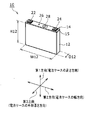
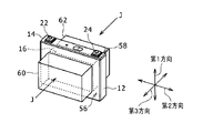
- FIG. 1 is an external perspective view of the non-aqueous electrolyte secondary battery 10.
- the non-aqueous electrolyte secondary battery 10 is referred to as a secondary battery 10.
- the secondary battery 10 is a square lithium-ion battery having a bottomed tubular rectangular parallelepiped battery case 12 having a rectangular opening on the ceiling side and a lid 14 for closing the rectangular opening of the battery case 12.
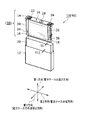
- FIG. 2 is a cross-sectional view showing the internal structure of the secondary battery 10 by separating the battery case 12 and the lid 14.
- a flat wound electrode body 16 in which a positive electrode and a negative electrode are laminated and wound via a separator and wound flat is included.
- the flat winding electrode body 16 is referred to as an electrode body 16.
- a non-aqueous electrolytic solution 18 impregnated in the electrode body 16 and an insulator for electrically insulating the electrode body 16 and the battery case 12 are provided.
- a certain electrode body holder 20 is included.
- FIG. 1 shows the first direction, the second direction, and the third direction as the three orthogonal directions.
- the first direction is a direction from the bottom of the battery case 12 toward the lid 14, and corresponds to the height direction of the battery case 12.
- the second direction is the direction in which the long side of the rectangular opening of the battery case 12 extends, and corresponds to the width direction of the battery case 12.
- the third direction is the direction in which the short side of the rectangular opening of the battery case 12 extends, and corresponds to the outer thickness direction of the battery case 12. The same applies to the following figure.
- the battery case 12 is a square can body having a rectangular opening, and a suitable metal material integrally molded into a predetermined shape is used.
- the outer dimension height which is the outer dimension of the battery case 12 as a single unit along the first direction, is H12
- the outer dimension width which is the outer dimension along the second direction, is W12
- the outer dimension is along the third direction.
- the outer dimension thickness is shown as D12.
- the external dimensions of the battery case 12 as a single unit are the external dimensions of the battery case 12 in a state where nothing is housed in a bottomed tubular rectangular parallelepiped having a rectangular opening on the ceiling side.
- the length of the long side of the rectangular opening of the battery case 12 as a single unit is W12 in the external dimension along the second direction.
- the length of the short side of the rectangular opening of the battery case 12 is D12 in the external dimension along the third direction.
- the external dimensions of the five sides of the battery case 12 are (W12 ⁇ H12) for the two sides having the long sides of the rectangular opening and (D12 ⁇ H12) for the two sides having the short sides of the rectangular opening.
- One side surface composed of the long side and the short side of the rectangular opening is (W12 ⁇ D12).
- the size of the battery case 12 as a single unit is set according to the battery capacity (Ah) of the secondary battery 10.
- the wall thickness t12 of each wall portion of the battery case 12 may be appropriately set according to the size of the entire battery case 12, but the electrode body 16 is brought into a predetermined pressing state by the pressing performed during the charge / discharge inspection described later. Therefore, it is necessary to reduce the wall thickness appropriately.
- Aluminum or an aluminum alloy is often used as the material of the battery case 12 of the vehicle-mounted secondary battery 10, and the wall thickness of each wall portion in that case is set to t12 ⁇ 1.0 mm. The charge / discharge inspection and the predetermined pressing state will be described later.
- the lid 14 includes a rectangular plate portion 15 having a size capable of closing the rectangular opening of the battery case 12 in a liquid-tight manner.
- a material that can be integrated with the battery case 12 by joining such as welding is selected.
- the material of the rectangular plate portion 15 the same material as that of the battery case 12 can be used.
- the lid 14 has two external terminals, a positive electrode external terminal 22 and a negative electrode external terminal 24, which protrude outward in the first direction of the secondary battery 10 when integrated with the battery case 12, a liquid injection port 26, and a gas.
- a discharge port 28 is provided in the rectangular plate portion 15.
- the positive electrode external terminal 22 is electrically insulated from the rectangular plate portion 15 via an insulating member.
- the negative electrode external terminal 24 is electrically insulated from the rectangular plate portion 15 via an insulating member.
- the positive electrode external terminal 22 and the negative electrode external terminal 24 are connected to the electrode body positive electrode 34 and the electrode body negative electrode 36 of the electrode body 16 via the positive electrode current collector plate 30 and the negative electrode current collector plate 32, respectively.
- the lid body 38 with an electrode body is formed in which the electrode body 16 and the lid body 14 are mechanically and electrically integrated.
- the non-aqueous electrolyte solution 18 is not yet contained in the lid body 38 with an electrode body immediately after being mechanically and electrically integrated.
- the portion of the electrode body 16 of the lid body 38 with the electrode body does not electrically contact the inner wall portion of the battery case 12.
- it is a sheet body of an insulator formed into a shape that covers the portion related to the electrode body 16.
- an electrically insulating resin having resistance to the non-aqueous electrolytic solution 18 is used as the material of the electrode body holder 20.
- the wall thickness of the electrode body holder 20 is shown as t1.
- An example of t1 is about 0.15 mm.
- the portion of the electrode body 16 of the lid body 38 with the electrode body is inserted into the battery case 12 in which the electrode body holder 20 is arranged, and the battery case 12 and the lid body 14 are integrated by welding or the like. After that, it is an opening for injecting the non-aqueous electrolyte solution 18 into the battery case 12.
- the liquid injection port 26 is sealed, whereby the non-aqueous electrolyte secondary battery 40 before the inspection is formed.
- the non-aqueous electrolyte secondary battery 40 before the inspection becomes the secondary battery 10 as a commercial product after undergoing a predetermined charge / discharge inspection.
- the gas discharge port 28 is a gas vent for discharging gas to the outside of the secondary battery 10 when gas is generated when the secondary battery 10 is charged and discharged and the internal pressure of the secondary battery 10 exceeds a predetermined value. It's a hole.
- FIG. 3 is a flowchart showing the procedure of the manufacturing method of the secondary battery 10.
- FIG. 3 it begins with the formation of the wound electrode body 42 (see FIG. 4) (S10).
- the formed wound-shaped electrode body 42 is flattened and molded by press working to become an electrode body 16 (S12).
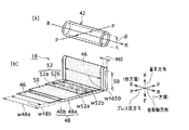
- FIG. 4A shows a perspective view of the wound electrode body 42
- FIG. 4B shows a developed view of the electrode body 16.
- the wound electrode body 42 has a thickness of one separator 46, one positive electrode plate 48, one separator 50, and one negative electrode plate 52. It is a winding body that is stacked in this order in the longitudinal direction and wound in a tubular shape around the winding shaft RR.
- d is the inner diameter dimension of the winding electrode body 42, and corresponds to, for example, the outer diameter dimension of the winding shaft body.
- the electrode body 16 is obtained by compression molding a tubular wound body of a wound electrode body 42 to a predetermined electrode body thickness M0 by press working.
- the electrode body 16 applies a press pressure to the wound electrode body 42 in the PP direction perpendicular to the winding shaft RR by using a press working machine to form a tubular shape of the wound electrode body 42. Obtained by molding into a flat shape.
- the inner diameter d of the wound electrode body 42 is crushed by press working, and the electrode body 16 has a linear innermost wound portion dimension S0 with almost no gap in the inner peripheral portion. ..
- FIG. 4B shows the RR direction, the PP direction, and the FF direction as three orthogonal directions with respect to the electrode body 16.
- the RR direction is the winding axis direction
- the PP direction is the press pressure direction of the press working to make a flat shape.
- the FF direction is orthogonal to both the RR direction and the PP direction, and is a direction in which a flat flat portion is stretched by press working, and is therefore referred to as a flat direction.
- the FF direction in the flat direction is parallel to the first direction
- the RR in the winding axis direction is parallel.
- the direction is parallel to the second direction
- the PP direction in the press pressure direction is parallel to the third direction.
- the state of development on the outermost peripheral side is shown. That is, the outermost circumference is the separator 46, and the positive electrode plate 48 is laminated on the separator 46, the separator 50 is laminated on the positive electrode plate 48, and the negative electrode plate 52 is laminated on the separator 50.
- the innermost peripheral side is the negative electrode plate 52, but this is an example for explanation, and the outermost peripheral side may be the negative electrode plate 52 and the innermost peripheral side may be the positive electrode plate 48.
- the positive electrode plate 48 is formed by applying and drying a positive electrode active material mixture layer 48b as a positive electrode slurry on both surfaces of an aluminum-based metal foil 48a which is a positive electrode core as a conductive metal current collecting plate.
- the positive electrode active material mixture layer 48b has a positive electrode active material.
- the aluminum-based metal is aluminum or an aluminum alloy mainly composed of aluminum.
- the positive electrode active material contains a lithium transition metal composite oxide capable of occluding and releasing lithium ions.
- the negative electrode plate 52 is formed by applying and drying a negative electrode active material mixture layer 52b as a negative electrode slurry on both surfaces of a copper-based metal foil 52a which is a negative electrode core as a conductive metal current collector plate.
- the negative electrode active material mixture layer 52b has a negative electrode active material.
- the copper-based metal is copper or a copper alloy mainly composed of copper.
- the negative electrode active material is a carbonaceous material.
- the separators 46 and 50 are films arranged between the positive electrode plate 48 and the negative electrode plate 52 and made of an ion-permeable material.
- FIG. 4B shows the dimensions of the positive electrode plate 48, the negative electrode plate 52, and the separators 46 and 50 along the winding axis direction of the electrode body 16.
- the width dimension of the aluminum-based metal foil 48a of the positive electrode plate 48 is shown as the positive electrode core body width w48a
- the width dimension of the positive electrode active material mixture layer 48b is shown as the positive electrode coating width w48b
- the width dimension of the copper-based metal foil 52a of the negative electrode plate 52 is shown as the negative electrode core body width w52a
- the width dimension of the negative electrode active material mixture layer 52b is shown as the negative electrode coating width w52b.
- the width dimension of the separators 46 and 50 is shown as the separator width w4650. These width dimensions are dimensions along the winding axis direction.
- the positive electrode coating width w48b is set narrower than the positive electrode core body width w48a, and the positive electrode coating width w48b is arranged closer to the other end side of both ends in the width direction of the positive electrode core body width w48a.
- a width region is formed on one end side along the winding axis direction in which the positive electrode active material mixture layer 48b is not applied and the aluminum-based metal foil 48a is exposed. The width region where the aluminum-based metal foil 48a is exposed is used as the electrode body positive electrode 34 at one end along the winding axis of the electrode body 16.
- the negative electrode coating width w52b is set narrower than the negative electrode core body width w52a, and the negative electrode coating width w52b is arranged closer to one end side of both ends of the negative electrode core body width w52a in the width direction.
- a width region is formed on the other end side along the winding axis direction in which the negative electrode active material mixture layer 52b is not applied and the copper-based metal foil 52a is exposed. The width region where the copper-based metal foil 52a is exposed is used as the electrode body negative electrode 36 at the other end portion along the winding axis of the electrode body 16.
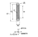
- FIG. 5 is a cross-sectional view of the electrode body 16 perpendicular to the winding axis direction.
- the thickness M0 of the electrode body 16 is a thickness dimension parallel to the press pressure direction, and when the electrode body 16 is housed in the battery case 12, it is parallel to the third direction which is the thickness direction of the battery case 12. Thickness dimension.
- the total length L0 along the flat direction of the electrode body 16 has a dimension parallel to the first direction, which is the height direction of the battery case 12, when the electrode body 16 is housed in the battery case 12.
- the dimension F0 in which the flat flat portion of the electrode body 16 extends in the flat direction is shorter than the total length L0 and longer than the dimension S0 of the innermost winding portion along the flat direction. That is, the relationship is L0> F0> S0.
- FIG. 6 is an enlarged view of the VI portion of FIG.
- the positive electrode plate 48 is coated with the positive electrode active material mixture layer 48b on both sides of the aluminum metal foil 48a
- the negative electrode plate 52 is coated with the negative electrode active material mixture layer 52b on both sides of the copper metal leaf 52a.
- the separators 46 and 50 are arranged between the positive electrode active material mixture layer 48b and the negative electrode active material mixture layer 52b. Since the separators 46 and 50 have ion permeability, when the electrode body 16 is immersed in the non-aqueous electrolytic solution 18, ions can flow between the positive electrode plate 48 and the negative electrode plate 52, and the electrode body 16 is charged and discharged. It will be in a possible state.
- the lid body 38 with the electrode body is formed (S14).
- the electrode body 16 has an electrode body positive electrode 34 at one end in the winding direction and an electrode body negative electrode 36 at the other end. Therefore, the electrode body positive electrode 34 of the electrode body 16 is connected to the positive electrode external terminal 22 of the lid 14 via the positive electrode current collector plate 30, and the electrode body negative electrode 36 of the electrode body 16 is connected via the negative electrode current collector plate 32. Then, it is connected to the negative electrode external terminal 24 of the lid body 14 to form the lid body 38 with the electrode body (see FIG. 2).
- the battery case 12 and the lid 14 are integrated (S16).
- the electrode body holder 20 is arranged in the rectangular tubular internal space of the battery case 12.
- the winding axis direction of the electrode body 16 is parallel to the second direction of the battery case 12, and the periphery of the electrode body 16 of the electrode body lid 38 is covered with the electrode body holder 20.
- the lid 38 with the electrode body is inserted into the internal space of the battery case 12 along the first direction of the battery case 12.
- the lid 38 with the electrode body covers the ceiling side opening of the battery case 12 and is arranged without a gap
- the mating portion between the battery case 12 and the lid 14 is connected to the battery by using a joining means such as welding.
- the case 12 and the lid 14 are integrated.
- the non-aqueous electrolytic solution 18 having a predetermined injection amount Q is injected using the injection port 26 of the lid 14.
- ethylene carbonate (EC), ethyl methyl carbonate (EMC), dimethyl carbonate (DMC), or the like is used as a non-aqueous solvent, and lithium hexafluorophosphate (LiPF 6 ) is added as an electrolyte salt. Is used. This is an example for explanation, and other composition substances can be used according to the specifications of the non-aqueous electrolyte secondary battery 10.
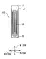
- FIG. 7 is a cross-sectional view of the non-aqueous electrolyte secondary battery 40 before the inspection.
- a charge / discharge inspection is performed before the non-aqueous electrolyte secondary battery 10 is shipped as a product, but the electrode body 16 is bent by the charge / discharge.
- the charge / discharge inspection is performed in a predetermined pressing state so as not to prevent the charge / discharge. Therefore, before the charge / discharge inspection, the non-aqueous electrolyte secondary battery 40 is pressed in a predetermined pressing state (S20).
- the pressing is a side surface perpendicular to the third direction of the battery case 12, including the long side of the rectangular opening of the battery case 12, and the battery case 12 with respect to the two side surfaces 56, 58 having an outer area of (W12 ⁇ H12). It is applied from the outside of the above using the pressing jigs 60 and 62.
- FIG. 8 shows a state in which the pressing jig 60 is addressed to the side surface 56, the pressing jig 62 is addressed to the side surface 58, and the pressing J is applied in the opposite directions.
- the pressing jigs 60 and 62 are addressed to predetermined pressing areas on the side surfaces 56 and 58.
- the predetermined pressing region is set according to the accommodation position of the electrode body 16 in the battery case 12.
- the length of the predetermined pressing region along the second direction may be the total length of the electrode body 16 along the second direction.
- the length L1 along the first direction of the predetermined pressing region is set according to the flat winding shape of the electrode body 16.
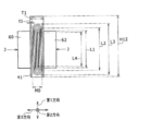
- FIG. 9 is a cross-sectional view cut along the pressing direction of the pressing J of FIG.
- the setting of the length L1 along the first direction of the predetermined pressing region will be described with reference to FIG.
- the length of the flat flat portion of the electrode body 16 along the first direction is L2.
- the total length of the electrode body 16 along the first direction is L3.
- the length between both ends of the electrode body 16 along the first direction of the innermost winding portion is L4.
- the length L4 between both ends of the innermost winding portion of the electrode body 16 is such that the position of the bent portion closest to the winding start in the innermost winding portion of the electrode body 16 is the first bending portion A.
- the position of the first bent portion on the side opposite to the first bent portion A along one direction is defined as the second bent portion B, which is the length between AB.
- the length L1 along the first direction of the predetermined pressing region is set so as to satisfy L1 ⁇ L2, L1 ⁇ L3, and L1 ⁇ L4.
- the ratio of the total thickness E1 of the inserts arranged in the battery case 12 to the inner dimension T1 of the battery case 12 is defined as the occupancy rate N1 in the battery case of the inserts, and 0.92 ⁇
- the pressing J is set so that N1 ⁇ 0.98.
- T1 and E1 that define N1 are values in the pressed state.
- FIG. 9 shows the relationship between T1, M0, and t1 in the pressed state.
- the inner dimension T1 of the battery case 12 is the inner dimension of the opening on the short side of the rectangular opening when the insert and the non-aqueous electrolytic solution 18 are placed in the internal space of the battery case 12 and the pressing J is applied.
- the inner dimension T1 is different from the inner dimension of the opening on the short side of the rectangular opening in the battery case 12 as a single unit described in FIG.
- the thickness M0 of the electrode body 16 is the thickness M0 of the electrode body 16 as a simple substance described in FIG. Since the wall thickness t1 of the electrode body holder 20 is smaller than that of T1 and M0, the influence of the non-aqueous electrolytic solution 18 and the pressing J may be ignored.
- the predetermined charge / discharge inspection can include, for example, an initial charging step, a high temperature aging step, and a characteristic confirmation step.
- the initial charging step for example, the SOC is charged to 40 to 80% in an environment of 25 ° C.
- the high temperature aging step is left for 12 to 24 hours in an environment of 60 ° C. or higher, for example.
- the characteristic confirmation step for example, in an environment of 25 ° C., the SOC is charged to 100% and then discharged to 0%.
- the non-aqueous electrolyte secondary battery 10 can be shipped as a product (S24).
- the electrode body 16 immediately after being formed by press working has almost no gap in the inner peripheral portion, and the innermost peripheral winding portion has a state of being linearly stretched in dimension S0.
- the innermost winding portion is not linear and bends. Deformation from a linear shape to a non-linear shape can be considered as a kind of buckling. Therefore, the bending of the electrode body 16 due to charging / discharging is evaluated using the buckling index value described below.
- the actual length along the locus path of the innermost winding locus connecting both ends of the innermost winding locus of the electrode body 16 is defined as C1, and the innermost winding locus.
- S1 be the straight line distance connecting both ends of.
- (C1 / S1) 1.000, and when bending occurs in the innermost winding portion, C1> S1 and (C1 / S1).
- (C1 / S1) is used as the buckling index value.
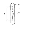
- the innermost winding locus of the electrode body 16 after the charge / discharge inspection can be measured by using the X-ray CT method.
- FIG. 10 shows an example of an X-ray CT image of the electrode body 16 after the charge / discharge inspection.
- images of a plurality of windings of the positive electrode plate 48, the negative electrode plate 52, and the separators 46 and 50 are omitted.
- the innermost winding locus 70 is considerably bent.
- the actual length C1 along the locus path of the innermost winding locus 70 is considerably longer than the distance S1 between both ends of the straight line 72 connecting both ends of the innermost winding locus 70, and (C1 / S1) is 1. It is a value well over 000.
- the contents of various parameters on the vertical axis of Table 1 are arranged as follows from the upper side to the lower side on the paper.
- the unit of dimension is mm
- the unit of liquid injection amount is g
- the unit of battery capacity is Ah.
- the positive electrode core body width w48a, the positive electrode coating width w48b, the negative electrode core body width w52a, the negative electrode coating width w52b, and the separator width w4650 is the thickness M0 of the electrode body 16 after pressing.
- the 7th to 10th steps counting from the top step are the outer dimension thickness D12 along the third direction of the battery case 12 as a single unit, the outer dimension width W12 along the second direction, and along the first direction.
- the outer dimension height is H12, and the wall thickness of the battery case 12 is t12.
- the eleventh stage counting from the top stage is the injection amount Q of the non-aqueous electrolytic solution 18.
- the twelfth stage counting from the top stage is the inner dimension T1 along the third direction of the battery case 12 in the pressed state before the charge / discharge inspection.
- the 14th to 17th steps counted from the top step are the length L1 of the predetermined pressing region along the first direction and the lengths L2, L3, and L4 described in FIG.
- the 18th row counting from the top row is the buckling index value (C1 / S1).
- the 19th stage counting from the top stage is the battery capacity.
- the secondary batteries on the horizontal axis in Table 1 have an outer dimension thickness D12 of less than 17 mm along the third direction of the battery case 12 from the left side to the right side on the paper surface and up to the third from the left side.
- Example 1, Comparative Example 1, and Example 2 as examples are arranged side by side. From the fourth onward counting from the leftmost side, Comparative Example 2, Example 3, Comparative Example 3, Comparative Example 4, as an example in which the outer dimension thickness D12 along the third direction of the battery case 12 is 17 mm or more and 27 mm or less. Comparative Example 5 and Example 4 were arranged side by side.
- the detailed contents of these nine secondary batteries are as follows.
- the battery capacity is 4Ah.
- the non-aqueous electrolyte secondary battery 40 of Example 1 was subjected to a predetermined charge / discharge inspection. It was pressed by the pressing jigs 60 and 62 before the charge / discharge inspection. Unless otherwise specified, the pressing jigs 60 and 62 used to press the entire surfaces of the side surfaces 56 and 58 of the non-aqueous electrolyte secondary battery 40.
- the buckling index value (C1 / S1) after the charge / discharge test was 1.0005, which was 1.001 or less.
- the battery capacity is 5 Ah.
- a predetermined charge / discharge test was performed on the non-aqueous electrolyte secondary battery 40 of Comparative Example 1. It was pressed by the pressing jigs 60 and 62 before the charge / discharge inspection.
- the buckling index value (C1 / S1) 1.0171 after the charge / discharge test, which was 1.001 or more.
- an electrode body holder 20 having a thickness of 0.15 mm
- the conditions of the battery case 12 are the same as those of Comparative Example 1.
- the battery capacity is 5 Ah.
- the non-aqueous electrolyte secondary battery 40 of Example 2 was subjected to a predetermined charge / discharge inspection. It was pressed by the pressing jigs 60 and 62 before the charge / discharge inspection.
- the buckling index value (C1 / S1) after the charge / discharge test was 1.0006, which was 1.001 or less.
- the battery capacity is 8 Ah.
- a predetermined charge / discharge test was performed on the non-aqueous electrolyte secondary battery 40 of Comparative Example 2. It was pressed by the pressing jigs 60 and 62 before the charge / discharge inspection.
- the buckling index value (C1 / S1) 1.0052 after the charge / discharge test, which was 1.001 or more.
- the non-aqueous electrolyte secondary battery 40 of Example 3 was subjected to a predetermined charge / discharge inspection. It was pressed by the pressing jigs 60 and 62 before the charge / discharge inspection.
- L1 ⁇ L2, L1 ⁇ L3, and L1 ⁇ L4. Pressing was performed in this predetermined pressing region, and the occupancy of the insert in the battery case was N1 0.96.
- the buckling index value (C1 / S1) after the charge / discharge test was 1.0007, which was 1.001 or less.
- the battery capacity is 25 Ah.
- a predetermined charge / discharge test was performed on the non-aqueous electrolyte secondary battery 40 of Comparative Example 3. It was pressed by the pressing jigs 60 and 62 before the charge / discharge inspection.
- the buckling index value (C1 / S1) after the charge / discharge test was 1.0128, which was 1.001 or more.
- the battery capacity is 35 Ah.
- a predetermined charge / discharge test was performed on the non-aqueous electrolyte secondary battery 40 of Comparative Example 4. It was pressed by the pressing jigs 60 and 62 before the charge / discharge inspection.
- the buckling index value (C1 / S1) 1.0148 after the charge / discharge test, which was 1.001 or more.
- a predetermined charge / discharge test was performed on the non-aqueous electrolyte secondary battery 40 of Comparative Example 5. It was pressed by the pressing jigs 60 and 62 before the charge / discharge inspection.
- the buckling index value (C1 / S1) 1.0079 after the charge / discharge test, which was 1.001 or more.
- the battery capacity is 25 Ah.
- the non-aqueous electrolyte secondary battery 40 of Example 4 was subjected to a predetermined charge / discharge inspection. It was pressed by the pressing jigs 60 and 62 before the charge / discharge inspection.
- the buckling index value (C1 / S1) 1.0004 after the charge / discharge test, which was 1.001 or less.
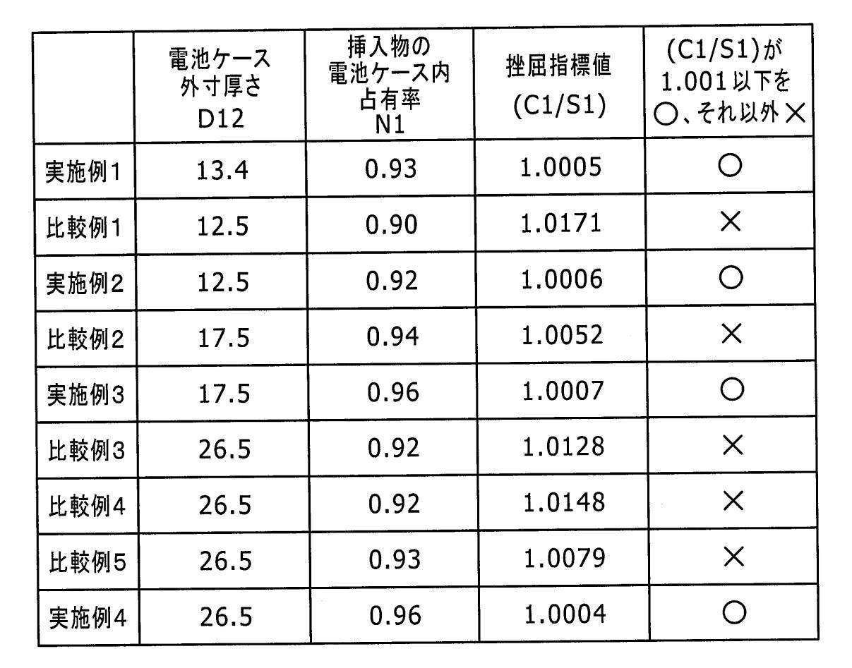
- Table 2 shows the relationship between the occupancy rate N1 in the battery case of the insert and the buckling index value (C1 / S1) for 4 Examples and 5 Comparative Examples from Table 1.
- the outer dimension thickness D12 of each battery case 12 is also shown.
- the buckling index value (C1 / S1) ⁇ 1.001 is set as the electrode body 16.
- the acceptance standard value for the deflection of the following can be found.
- the outer dimension thickness of the battery case 12 is 12 mm or more in order to make the buckling index value (C1 / S1) ⁇ 1.001. If it is less than 17 mm, it is pressed so that 0.92 ⁇ N1 ⁇ 0.98. When the outer dimension thickness of the battery case 12 is 17 mm or more and 27 mm or less, the battery case 12 is pressed so as to have 0.94 ⁇ N1 ⁇ 0.98. In this way, the bending of the electrode body 16 can be effectively suppressed by pressing the insert to occupy the battery case N1 appropriately according to the size of the battery case 12.
- the insert is pressed from the outside of the battery case 12 so that the occupancy rate N1 in the battery case of the insert is appropriate according to the size of the battery case 12. Then perform a charge / discharge inspection.
- the occurrence of distortion due to the expansion and contraction of the electrode plate caused by charging and discharging and to suppress the occurrence of bending, which is buckling of the flat spirally wound electrode body 16.
- the flat wound wound electrode body 16 is bent, the distance between the electrodes increases and the cell resistance increases. In addition, the bending causes a high stress portion, and the reaction force increases.
- the overvoltage increases, irreversible deterioration such as decomposition of the electrolytic solution, Li precipitation, and elution of the positive electrode active material occurs, and the durability is lowered.
- the method for producing the non-aqueous electrolyte secondary battery 10 having the above configuration it is possible to provide the non-aqueous electrolyte secondary battery 10 which suppresses these and is excellent in low resistance, low reaction force, and durability.
- the non-aqueous electrolyte secondary battery 40 by restraining the non-aqueous electrolyte secondary battery 40 before the inspection from the outside during the charge / discharge inspection of the non-aqueous electrolyte secondary battery 40, it is possible to suppress the gas accumulation generated during the charge / discharge inspection, and the charge / discharge can be suppressed. It is possible to shorten the inspection time and improve the accuracy of voltage inspection.
Landscapes
- Chemical & Material Sciences (AREA)
- Chemical Kinetics & Catalysis (AREA)
- Electrochemistry (AREA)
- General Chemical & Material Sciences (AREA)
- Engineering & Computer Science (AREA)
- Manufacturing & Machinery (AREA)
- Materials Engineering (AREA)
- Physics & Mathematics (AREA)
- General Physics & Mathematics (AREA)
- Secondary Cells (AREA)
Abstract
Description

12 電池ケース
14 蓋体
15 矩形板部
16 (扁平状巻回形)電極体
18 非水電解液
20 電極体ホルダー(絶縁体)
22 正極外部端子
24 負極外部端子
26 注液口
28 ガス排出口
30 正極集電板
32 負極集電板
34 電極体正極
36 電極体負極
38 電極体付蓋体
40 (検査前の)非水電解質二次電池
42 巻回形電極体
46,50 セパレータ
48 正極板
48a アルミニウム系金属箔
48b 正極活物質合剤層
52 負極板
52a 銅系金属箔
52b 負極活物質合剤層
56,58 側面
60,62 押圧治具
70 最内周巻回軌跡
72 直線
Claims (7)
- 正極板、負極板、及び、前記正極板と前記負極板との間に配置されイオン透過性を有するセパレータとを用いて扁平状巻回形電極体を作製する工程、
前記扁平状巻回形電極体を含む挿入物を、開口を有する電池ケースに収容する工程、
前記電池ケースの前記開口を蓋体を用いて閉じる工程、
前記電池ケース内に非水電解液を注入する工程、
を含む非水電解質二次電池の製造工程を経た後、
前記電池ケースの外側の所定押圧領域を押圧治具で押圧し、
押圧状態の前記電池ケースにおいて前記扁平状巻回形電極体の厚さ方向に平行な方向に沿って前記扁平状巻回形電極体を含む前記電池ケース内への挿入物の合計厚さE1と前記電池ケースの内寸T1の比率(E1/T1)を前記挿入物の電池ケース内占有率N1として、0.92≦N1<0.98の所定押圧状態とし、
前記所定押圧状態の下で充放電検査を実行する工程を含む、非水電解質二次電池の製造方法。 - 前記電池ケースの外寸厚さは、12mm以上27mm以下であり、
前記所定押圧状態は、
前記電池ケースの外寸厚さが12mm以上17mm未満の場合には、0.92≦N1<0.98であり、
前記電池ケースの外寸厚さが17mm以上27mm以下の場合には、0.94<N1<0.98である、請求項1に記載の非水電解質二次電池の製造方法。 - 前記扁平状巻回形電極体において巻回軸方向に垂直で且つ扁平状の平坦部が延伸する方向を第1方向として、
前記扁平状巻回形電極体の扁平状の前記平坦部の前記第1方向に沿った長さをL2とし、
前記扁平状巻回形電極体の前記第1方向に沿った全体の長さをL3とし、
前記扁平状巻回形電極体の最内周巻回部分の前記第1方向に沿った両端部間の長さをL4として、
前記所定押圧領域の前記第1方向に沿った長さL1は、L1≦L2,L1<L3,L1≧L4に設定されている、請求項1に記載の非水電解質二次電池の製造方法。 - 前記電池ケースは、アルミニウム、またはアルミニウム合金で構成され、
前記電池ケースにおける前記所定押圧領域に対応する部分の肉厚は1.00mm以下である、請求項1に記載の非水電解質二次電池の製造方法。 - 所定の前記充放電検査の実行後において、前記扁平状巻回形電極体の最内周巻回部分の両端を結ぶ最内周巻回軌跡の軌跡経路に沿った実際の長さをC1とし、前記最内周巻回軌跡の両端を結ぶ直線距離をS1として、1.000<(C1/S1)<1.001である、請求項1に記載の非水電解質二次電池の製造方法。
- 前記挿入物は、前記扁平状巻回形電極体、及び、前記電池ケースと前記扁平状巻回形電極体との間の電極体ホルダーを備え、
前記扁平状巻回形電極体は、厚さがM0であり、
前記電極体ホルダーは、肉厚がt1であり、
前記扁平状巻回形電極体を含む前記電池ケース内への前記挿入物の合計厚さC1は(M0+2×t1)であり、
前記挿入物の前記電池ケース内占有率N1は、N1=(M0+2×t1)/T1である、請求項1に記載の非水電解質二次電池の製造方法。 - 正極板、負極板、及び、前記正極板と前記負極板との間に配置されイオン透過性を有するセパレータを備える扁平状巻回形電極体を、非水電解質と共に電池ケースに収納する非水電解質二次電池であって、
前記扁平状巻回形電極体は、最内周巻回部分の両端を結ぶ最内周巻回軌跡の軌跡経路に沿った実際の長さをC1とし、前記最内周巻回軌跡の両端を結ぶ直線距離をS1として、1.000<(C1/S1)<1.001である、非水電解質二次電池。
Priority Applications (4)
| Application Number | Priority Date | Filing Date | Title |
|---|---|---|---|
| CN202080068432.XA CN114450835B (zh) | 2019-09-30 | 2020-07-01 | 非水电解质二次电池的制造方法和非水电解质二次电池 |
| US17/635,846 US12388121B2 (en) | 2019-09-30 | 2020-07-01 | Method for producing nonaqueous electrolyte secondary battery, and nonaqueous electrolyte secondary battery |
| JP2021550340A JP7621265B2 (ja) | 2019-09-30 | 2020-07-01 | 非水電解質二次電池の製造方法及び非水電解質二次電池 |
| EP20872725.5A EP4040563A4 (en) | 2019-09-30 | 2020-07-01 | METHOD FOR PRODUCING A SECONDARY BATTERY WITH ANHYDROUS ELECTROLYTE AND SECONDARY BATTERY WITH ANHYDROUS ELECTROLYTE |
Applications Claiming Priority (2)
| Application Number | Priority Date | Filing Date | Title |
|---|---|---|---|
| JP2019-180169 | 2019-09-30 | ||
| JP2019180169 | 2019-09-30 |
Publications (1)
| Publication Number | Publication Date |
|---|---|
| WO2021065128A1 true WO2021065128A1 (ja) | 2021-04-08 |
Family
ID=75336956
Family Applications (1)
| Application Number | Title | Priority Date | Filing Date |
|---|---|---|---|
| PCT/JP2020/025843 Ceased WO2021065128A1 (ja) | 2019-09-30 | 2020-07-01 | 非水電解質二次電池の製造方法及び非水電解質二次電池 |
Country Status (5)
| Country | Link |
|---|---|
| US (1) | US12388121B2 (ja) |
| EP (1) | EP4040563A4 (ja) |
| JP (1) | JP7621265B2 (ja) |
| CN (1) | CN114450835B (ja) |
| WO (1) | WO2021065128A1 (ja) |
Cited By (2)
| Publication number | Priority date | Publication date | Assignee | Title |
|---|---|---|---|---|
| JP2025516103A (ja) * | 2022-05-12 | 2025-05-27 | ビーワイディー カンパニー リミテッド | バッテリ、バッテリパック、および車両 |
| JP2025542361A (ja) * | 2023-06-21 | 2025-12-25 | 寧徳時代新能源科技股▲分▼有限公司 | 電池セル、電池、電力消費装置及びエネルギー貯蔵装置 |
Families Citing this family (1)
| Publication number | Priority date | Publication date | Assignee | Title |
|---|---|---|---|---|
| WO2021065128A1 (ja) * | 2019-09-30 | 2021-04-08 | 三洋電機株式会社 | 非水電解質二次電池の製造方法及び非水電解質二次電池 |
Citations (13)
| Publication number | Priority date | Publication date | Assignee | Title |
|---|---|---|---|---|
| JP2001291526A (ja) * | 2000-04-10 | 2001-10-19 | Nec Mobile Energy Kk | 密閉型電池およびその製造方法 |
| JP2004047332A (ja) * | 2002-07-12 | 2004-02-12 | Toyota Motor Corp | 角型二次電池の設計方法 |
| JP2004259485A (ja) * | 2003-02-24 | 2004-09-16 | Japan Storage Battery Co Ltd | 非水電解質二次電池 |
| JP2007103295A (ja) * | 2005-10-07 | 2007-04-19 | Gs Yuasa Corporation:Kk | 非水電解質二次電池 |
| JP2008047304A (ja) * | 2006-08-10 | 2008-02-28 | Mitsui Mining & Smelting Co Ltd | 非水電解液二次電池 |
| JP2009104902A (ja) * | 2007-10-23 | 2009-05-14 | Mitsui Mining & Smelting Co Ltd | 非水電解液二次電池の製造方法 |
| JP2010021104A (ja) * | 2008-07-14 | 2010-01-28 | Toyota Motor Corp | 二次電池の製造方法 |
| JP2013115033A (ja) | 2011-12-01 | 2013-06-10 | Hitachi Vehicle Energy Ltd | 角形リチウムイオン電池 |
| JP2013125650A (ja) | 2011-12-14 | 2013-06-24 | Toyota Motor Corp | 密閉型リチウム二次電池とその製造方法 |
| JP2014056728A (ja) * | 2012-09-13 | 2014-03-27 | Toyota Motor Corp | 非水電解質二次電池 |
| JP2014082157A (ja) | 2012-10-18 | 2014-05-08 | Hitachi Vehicle Energy Ltd | リチウムイオン二次電池 |
| JP2015065065A (ja) * | 2013-09-25 | 2015-04-09 | 株式会社豊田自動織機 | 蓄電装置の製造方法 |
| WO2018008135A1 (ja) * | 2016-07-07 | 2018-01-11 | 三菱電機株式会社 | バッテリーケース、電池セル、バッテリーモジュールおよびバッテリーモジュールの製造方法 |
Family Cites Families (13)
| Publication number | Priority date | Publication date | Assignee | Title |
|---|---|---|---|---|
| JP4599051B2 (ja) * | 2003-11-11 | 2010-12-15 | 株式会社東芝 | 角形非水電解質二次電池 |
| JP5260857B2 (ja) * | 2006-11-13 | 2013-08-14 | 三洋電機株式会社 | 角形非水電解質二次電池及びその製造方法 |
| JP4296205B2 (ja) | 2007-03-29 | 2009-07-15 | 株式会社東芝 | 非水電解質電池、電池パック及び自動車 |
| JP4560079B2 (ja) * | 2007-08-09 | 2010-10-13 | パナソニック株式会社 | 非水電解質二次電池用正極の製造方法 |
| KR20120022722A (ko) * | 2010-04-27 | 2012-03-12 | 파나소닉 주식회사 | 비수계 이차전지 및 이것에 이용하는 전극군 |
| JP2012204179A (ja) * | 2011-03-25 | 2012-10-22 | Toyota Motor Corp | 非水電解液二次電池 |
| JPWO2014156053A1 (ja) * | 2013-03-26 | 2017-02-16 | 三洋電機株式会社 | 非水電解質二次電池用負極及び非水電解質二次電池 |
| JP6036594B2 (ja) * | 2013-08-01 | 2016-11-30 | トヨタ自動車株式会社 | 非水電解質二次電池の製造方法、及び非水電解質二次電池 |
| US10320026B2 (en) * | 2014-10-21 | 2019-06-11 | Nec Corporation | Electrode for secondary battery and secondary battery using same |
| JP6210336B2 (ja) | 2015-05-15 | 2017-10-11 | トヨタ自動車株式会社 | 二次電池 |
| JP6106774B2 (ja) * | 2016-02-04 | 2017-04-05 | 日立オートモティブシステムズ株式会社 | 角形リチウムイオン電池 |
| WO2017183633A1 (ja) * | 2016-04-20 | 2017-10-26 | 日本電気株式会社 | 二次電池 |
| WO2021065128A1 (ja) * | 2019-09-30 | 2021-04-08 | 三洋電機株式会社 | 非水電解質二次電池の製造方法及び非水電解質二次電池 |
-
2020
- 2020-07-01 WO PCT/JP2020/025843 patent/WO2021065128A1/ja not_active Ceased
- 2020-07-01 JP JP2021550340A patent/JP7621265B2/ja active Active
- 2020-07-01 CN CN202080068432.XA patent/CN114450835B/zh active Active
- 2020-07-01 US US17/635,846 patent/US12388121B2/en active Active
- 2020-07-01 EP EP20872725.5A patent/EP4040563A4/en active Pending
Patent Citations (13)
| Publication number | Priority date | Publication date | Assignee | Title |
|---|---|---|---|---|
| JP2001291526A (ja) * | 2000-04-10 | 2001-10-19 | Nec Mobile Energy Kk | 密閉型電池およびその製造方法 |
| JP2004047332A (ja) * | 2002-07-12 | 2004-02-12 | Toyota Motor Corp | 角型二次電池の設計方法 |
| JP2004259485A (ja) * | 2003-02-24 | 2004-09-16 | Japan Storage Battery Co Ltd | 非水電解質二次電池 |
| JP2007103295A (ja) * | 2005-10-07 | 2007-04-19 | Gs Yuasa Corporation:Kk | 非水電解質二次電池 |
| JP2008047304A (ja) * | 2006-08-10 | 2008-02-28 | Mitsui Mining & Smelting Co Ltd | 非水電解液二次電池 |
| JP2009104902A (ja) * | 2007-10-23 | 2009-05-14 | Mitsui Mining & Smelting Co Ltd | 非水電解液二次電池の製造方法 |
| JP2010021104A (ja) * | 2008-07-14 | 2010-01-28 | Toyota Motor Corp | 二次電池の製造方法 |
| JP2013115033A (ja) | 2011-12-01 | 2013-06-10 | Hitachi Vehicle Energy Ltd | 角形リチウムイオン電池 |
| JP2013125650A (ja) | 2011-12-14 | 2013-06-24 | Toyota Motor Corp | 密閉型リチウム二次電池とその製造方法 |
| JP2014056728A (ja) * | 2012-09-13 | 2014-03-27 | Toyota Motor Corp | 非水電解質二次電池 |
| JP2014082157A (ja) | 2012-10-18 | 2014-05-08 | Hitachi Vehicle Energy Ltd | リチウムイオン二次電池 |
| JP2015065065A (ja) * | 2013-09-25 | 2015-04-09 | 株式会社豊田自動織機 | 蓄電装置の製造方法 |
| WO2018008135A1 (ja) * | 2016-07-07 | 2018-01-11 | 三菱電機株式会社 | バッテリーケース、電池セル、バッテリーモジュールおよびバッテリーモジュールの製造方法 |
Non-Patent Citations (1)
| Title |
|---|
| See also references of EP4040563A4 |
Cited By (3)
| Publication number | Priority date | Publication date | Assignee | Title |
|---|---|---|---|---|
| JP2025516103A (ja) * | 2022-05-12 | 2025-05-27 | ビーワイディー カンパニー リミテッド | バッテリ、バッテリパック、および車両 |
| JP2025542361A (ja) * | 2023-06-21 | 2025-12-25 | 寧徳時代新能源科技股▲分▼有限公司 | 電池セル、電池、電力消費装置及びエネルギー貯蔵装置 |
| JP2026501291A (ja) * | 2023-06-21 | 2026-01-14 | 寧徳時代新能源科技股▲分▼有限公司 | 電池セル、電池、電力消費装置及びエネルギー貯蔵装置 |
Also Published As
| Publication number | Publication date |
|---|---|
| JPWO2021065128A1 (ja) | 2021-04-08 |
| JP7621265B2 (ja) | 2025-01-24 |
| US20220302511A1 (en) | 2022-09-22 |
| EP4040563A4 (en) | 2024-07-24 |
| CN114450835B (zh) | 2024-08-16 |
| US12388121B2 (en) | 2025-08-12 |
| CN114450835A (zh) | 2022-05-06 |
| EP4040563A1 (en) | 2022-08-10 |
Similar Documents
| Publication | Publication Date | Title |
|---|---|---|
| CN113574720B (zh) | 二次电池的电池壳体和袋型二次电池 | |
| CN101978547B (zh) | 方形电池 | |
| US8758917B2 (en) | Secondary battery | |
| CN113711403B (zh) | 制造二次电池的设备和方法 | |
| CN113348575B (zh) | 制造二次电池的设备和方法 | |
| CN104303332A (zh) | 具有阶梯状结构的电池单体 | |
| US12021261B2 (en) | Stacked secondary battery | |
| WO2020059131A1 (ja) | 電池及び電池パック | |
| US20180219208A1 (en) | Lithium storage battery with integrated circuit-breaker for improved operating safety | |
| JP7621265B2 (ja) | 非水電解質二次電池の製造方法及び非水電解質二次電池 | |
| CN105474428A (zh) | 具有由两个或更多个构件构成的电池壳体的棱柱形电池单体 | |
| US20260045577A1 (en) | Pouch Type Battery Case and Pouch Type Secondary Battery | |
| JP4313992B2 (ja) | 角型二次電池の設計方法 | |
| CN115552684A (zh) | 二次电池 | |
| JP5923431B2 (ja) | リチウムイオン二次電池 | |
| CN120642084A (zh) | 圆筒形电池 | |
| US20150140382A1 (en) | Electric storage device and electric storage device module | |
| JP5914635B2 (ja) | 角形二次電池モジュール | |
| JP2006278184A (ja) | 角型電池及びその製造方法 | |
| JP7228548B2 (ja) | 非水電解質二次電池および組電池 | |
| WO2020017096A1 (ja) | 二次電池 | |
| JP7157907B2 (ja) | 端子の接合状態判定方法 | |
| JP2018195406A (ja) | 蓄電素子 | |
| JP2014036009A (ja) | リチウムイオン二次電池の製造方法 | |
| CN115810844A (zh) | 二次电池及该二次电池的制造方法 |
Legal Events
| Date | Code | Title | Description |
|---|---|---|---|
| 121 | Ep: the epo has been informed by wipo that ep was designated in this application |
Ref document number: 20872725 Country of ref document: EP Kind code of ref document: A1 |
|
| ENP | Entry into the national phase |
Ref document number: 2021550340 Country of ref document: JP Kind code of ref document: A |
|
| NENP | Non-entry into the national phase |
Ref country code: DE |
|
| ENP | Entry into the national phase |
Ref document number: 2020872725 Country of ref document: EP Effective date: 20220502 |
|
| WWG | Wipo information: grant in national office |
Ref document number: 202247015689 Country of ref document: IN |
|
| WWG | Wipo information: grant in national office |
Ref document number: 17635846 Country of ref document: US |