WO2021065303A1 - 空調換気システム - Google Patents
空調換気システム Download PDFInfo
- Publication number
- WO2021065303A1 WO2021065303A1 PCT/JP2020/033174 JP2020033174W WO2021065303A1 WO 2021065303 A1 WO2021065303 A1 WO 2021065303A1 JP 2020033174 W JP2020033174 W JP 2020033174W WO 2021065303 A1 WO2021065303 A1 WO 2021065303A1
- Authority
- WO
- WIPO (PCT)
- Prior art keywords
- air
- refrigerant
- predetermined value
- control unit
- ventilation
- Prior art date
- Legal status (The legal status is an assumption and is not a legal conclusion. Google has not performed a legal analysis and makes no representation as to the accuracy of the status listed.)
- Ceased
Links
Images
Classifications
-
- F—MECHANICAL ENGINEERING; LIGHTING; HEATING; WEAPONS; BLASTING
- F24—HEATING; RANGES; VENTILATING
- F24F—AIR-CONDITIONING; AIR-HUMIDIFICATION; VENTILATION; USE OF AIR CURRENTS FOR SCREENING
- F24F7/00—Ventilation
- F24F7/007—Ventilation with forced flow
-
- F—MECHANICAL ENGINEERING; LIGHTING; HEATING; WEAPONS; BLASTING
- F24—HEATING; RANGES; VENTILATING
- F24F—AIR-CONDITIONING; AIR-HUMIDIFICATION; VENTILATION; USE OF AIR CURRENTS FOR SCREENING
- F24F11/00—Control or safety arrangements
- F24F11/30—Control or safety arrangements for purposes related to the operation of the system, e.g. for safety or monitoring
- F24F11/32—Responding to malfunctions or emergencies
-
- F—MECHANICAL ENGINEERING; LIGHTING; HEATING; WEAPONS; BLASTING
- F24—HEATING; RANGES; VENTILATING
- F24F—AIR-CONDITIONING; AIR-HUMIDIFICATION; VENTILATION; USE OF AIR CURRENTS FOR SCREENING
- F24F11/00—Control or safety arrangements
- F24F11/30—Control or safety arrangements for purposes related to the operation of the system, e.g. for safety or monitoring
- F24F11/32—Responding to malfunctions or emergencies
- F24F11/36—Responding to malfunctions or emergencies to leakage of heat-exchange fluid
-
- F—MECHANICAL ENGINEERING; LIGHTING; HEATING; WEAPONS; BLASTING
- F24—HEATING; RANGES; VENTILATING
- F24F—AIR-CONDITIONING; AIR-HUMIDIFICATION; VENTILATION; USE OF AIR CURRENTS FOR SCREENING
- F24F11/00—Control or safety arrangements
- F24F11/30—Control or safety arrangements for purposes related to the operation of the system, e.g. for safety or monitoring
- F24F11/49—Control or safety arrangements for purposes related to the operation of the system, e.g. for safety or monitoring ensuring correct operation, e.g. by trial operation or configuration checks
-
- F—MECHANICAL ENGINEERING; LIGHTING; HEATING; WEAPONS; BLASTING
- F24—HEATING; RANGES; VENTILATING
- F24F—AIR-CONDITIONING; AIR-HUMIDIFICATION; VENTILATION; USE OF AIR CURRENTS FOR SCREENING
- F24F11/00—Control or safety arrangements
- F24F11/50—Control or safety arrangements characterised by user interfaces or communication
- F24F11/52—Indication arrangements, e.g. displays
-
- F—MECHANICAL ENGINEERING; LIGHTING; HEATING; WEAPONS; BLASTING
- F24—HEATING; RANGES; VENTILATING
- F24F—AIR-CONDITIONING; AIR-HUMIDIFICATION; VENTILATION; USE OF AIR CURRENTS FOR SCREENING
- F24F11/00—Control or safety arrangements
- F24F11/50—Control or safety arrangements characterised by user interfaces or communication
- F24F11/61—Control or safety arrangements characterised by user interfaces or communication using timers
-
- F—MECHANICAL ENGINEERING; LIGHTING; HEATING; WEAPONS; BLASTING
- F24—HEATING; RANGES; VENTILATING
- F24F—AIR-CONDITIONING; AIR-HUMIDIFICATION; VENTILATION; USE OF AIR CURRENTS FOR SCREENING
- F24F11/00—Control or safety arrangements
- F24F11/70—Control systems characterised by their outputs; Constructional details thereof
- F24F11/72—Control systems characterised by their outputs; Constructional details thereof for controlling the supply of treated air, e.g. its pressure
- F24F11/74—Control systems characterised by their outputs; Constructional details thereof for controlling the supply of treated air, e.g. its pressure for controlling air flow rate or air velocity
- F24F11/77—Control systems characterised by their outputs; Constructional details thereof for controlling the supply of treated air, e.g. its pressure for controlling air flow rate or air velocity by controlling the speed of ventilators
-
- F—MECHANICAL ENGINEERING; LIGHTING; HEATING; WEAPONS; BLASTING
- F24—HEATING; RANGES; VENTILATING
- F24F—AIR-CONDITIONING; AIR-HUMIDIFICATION; VENTILATION; USE OF AIR CURRENTS FOR SCREENING
- F24F11/00—Control or safety arrangements
- F24F11/70—Control systems characterised by their outputs; Constructional details thereof
- F24F11/80—Control systems characterised by their outputs; Constructional details thereof for controlling the temperature of the supplied air
- F24F11/86—Control systems characterised by their outputs; Constructional details thereof for controlling the temperature of the supplied air by controlling compressors within refrigeration or heat pump circuits
-
- F—MECHANICAL ENGINEERING; LIGHTING; HEATING; WEAPONS; BLASTING
- F24—HEATING; RANGES; VENTILATING
- F24F—AIR-CONDITIONING; AIR-HUMIDIFICATION; VENTILATION; USE OF AIR CURRENTS FOR SCREENING
- F24F11/00—Control or safety arrangements
- F24F11/89—Arrangement or mounting of control or safety devices
-
- F—MECHANICAL ENGINEERING; LIGHTING; HEATING; WEAPONS; BLASTING
- F24—HEATING; RANGES; VENTILATING
- F24F—AIR-CONDITIONING; AIR-HUMIDIFICATION; VENTILATION; USE OF AIR CURRENTS FOR SCREENING
- F24F12/00—Use of energy recovery systems in air conditioning, ventilation or screening
- F24F12/001—Use of energy recovery systems in air conditioning, ventilation or screening with heat-exchange between supplied and exhausted air
- F24F12/006—Use of energy recovery systems in air conditioning, ventilation or screening with heat-exchange between supplied and exhausted air using an air-to-air heat exchanger
-
- F—MECHANICAL ENGINEERING; LIGHTING; HEATING; WEAPONS; BLASTING
- F24—HEATING; RANGES; VENTILATING
- F24F—AIR-CONDITIONING; AIR-HUMIDIFICATION; VENTILATION; USE OF AIR CURRENTS FOR SCREENING
- F24F3/00—Air-conditioning systems in which conditioned primary air is supplied from one or more central stations to distributing units in the rooms or spaces where it may receive secondary treatment; Apparatus specially designed for such systems
- F24F3/06—Air-conditioning systems in which conditioned primary air is supplied from one or more central stations to distributing units in the rooms or spaces where it may receive secondary treatment; Apparatus specially designed for such systems characterised by the arrangements for the supply of heat-exchange fluid for the subsequent treatment of primary air in the room units
- F24F3/065—Air-conditioning systems in which conditioned primary air is supplied from one or more central stations to distributing units in the rooms or spaces where it may receive secondary treatment; Apparatus specially designed for such systems characterised by the arrangements for the supply of heat-exchange fluid for the subsequent treatment of primary air in the room units with a plurality of evaporators or condensers
-
- F—MECHANICAL ENGINEERING; LIGHTING; HEATING; WEAPONS; BLASTING
- F25—REFRIGERATION OR COOLING; COMBINED HEATING AND REFRIGERATION SYSTEMS; HEAT PUMP SYSTEMS; MANUFACTURE OR STORAGE OF ICE; LIQUEFACTION SOLIDIFICATION OF GASES
- F25B—REFRIGERATION MACHINES, PLANTS OR SYSTEMS; COMBINED HEATING AND REFRIGERATION SYSTEMS; HEAT PUMP SYSTEMS
- F25B13/00—Compression machines, plants or systems, with reversible cycle
-
- F—MECHANICAL ENGINEERING; LIGHTING; HEATING; WEAPONS; BLASTING
- F25—REFRIGERATION OR COOLING; COMBINED HEATING AND REFRIGERATION SYSTEMS; HEAT PUMP SYSTEMS; MANUFACTURE OR STORAGE OF ICE; LIQUEFACTION SOLIDIFICATION OF GASES
- F25B—REFRIGERATION MACHINES, PLANTS OR SYSTEMS; COMBINED HEATING AND REFRIGERATION SYSTEMS; HEAT PUMP SYSTEMS
- F25B49/00—Arrangement or mounting of control or safety devices
- F25B49/005—Arrangement or mounting of control or safety devices of safety devices
-
- F—MECHANICAL ENGINEERING; LIGHTING; HEATING; WEAPONS; BLASTING
- F25—REFRIGERATION OR COOLING; COMBINED HEATING AND REFRIGERATION SYSTEMS; HEAT PUMP SYSTEMS; MANUFACTURE OR STORAGE OF ICE; LIQUEFACTION SOLIDIFICATION OF GASES
- F25B—REFRIGERATION MACHINES, PLANTS OR SYSTEMS; COMBINED HEATING AND REFRIGERATION SYSTEMS; HEAT PUMP SYSTEMS
- F25B49/00—Arrangement or mounting of control or safety devices
- F25B49/02—Arrangement or mounting of control or safety devices for compression type machines, plants or systems
-
- F—MECHANICAL ENGINEERING; LIGHTING; HEATING; WEAPONS; BLASTING
- F25—REFRIGERATION OR COOLING; COMBINED HEATING AND REFRIGERATION SYSTEMS; HEAT PUMP SYSTEMS; MANUFACTURE OR STORAGE OF ICE; LIQUEFACTION SOLIDIFICATION OF GASES
- F25B—REFRIGERATION MACHINES, PLANTS OR SYSTEMS; COMBINED HEATING AND REFRIGERATION SYSTEMS; HEAT PUMP SYSTEMS
- F25B49/00—Arrangement or mounting of control or safety devices
- F25B49/02—Arrangement or mounting of control or safety devices for compression type machines, plants or systems
- F25B49/022—Compressor control arrangements
-
- F—MECHANICAL ENGINEERING; LIGHTING; HEATING; WEAPONS; BLASTING
- F24—HEATING; RANGES; VENTILATING
- F24F—AIR-CONDITIONING; AIR-HUMIDIFICATION; VENTILATION; USE OF AIR CURRENTS FOR SCREENING
- F24F2110/00—Control inputs relating to air properties
- F24F2110/50—Air quality properties
- F24F2110/65—Concentration of specific substances or contaminants
-
- F—MECHANICAL ENGINEERING; LIGHTING; HEATING; WEAPONS; BLASTING
- F25—REFRIGERATION OR COOLING; COMBINED HEATING AND REFRIGERATION SYSTEMS; HEAT PUMP SYSTEMS; MANUFACTURE OR STORAGE OF ICE; LIQUEFACTION SOLIDIFICATION OF GASES
- F25B—REFRIGERATION MACHINES, PLANTS OR SYSTEMS; COMBINED HEATING AND REFRIGERATION SYSTEMS; HEAT PUMP SYSTEMS
- F25B2313/00—Compression machines, plants or systems with reversible cycle not otherwise provided for
- F25B2313/023—Compression machines, plants or systems with reversible cycle not otherwise provided for using multiple indoor units
- F25B2313/0233—Compression machines, plants or systems with reversible cycle not otherwise provided for using multiple indoor units in parallel arrangements
-
- F—MECHANICAL ENGINEERING; LIGHTING; HEATING; WEAPONS; BLASTING
- F25—REFRIGERATION OR COOLING; COMBINED HEATING AND REFRIGERATION SYSTEMS; HEAT PUMP SYSTEMS; MANUFACTURE OR STORAGE OF ICE; LIQUEFACTION SOLIDIFICATION OF GASES
- F25B—REFRIGERATION MACHINES, PLANTS OR SYSTEMS; COMBINED HEATING AND REFRIGERATION SYSTEMS; HEAT PUMP SYSTEMS
- F25B2313/00—Compression machines, plants or systems with reversible cycle not otherwise provided for
- F25B2313/029—Control issues
- F25B2313/0293—Control issues related to the indoor fan, e.g. controlling speed
-
- F—MECHANICAL ENGINEERING; LIGHTING; HEATING; WEAPONS; BLASTING
- F25—REFRIGERATION OR COOLING; COMBINED HEATING AND REFRIGERATION SYSTEMS; HEAT PUMP SYSTEMS; MANUFACTURE OR STORAGE OF ICE; LIQUEFACTION SOLIDIFICATION OF GASES
- F25B—REFRIGERATION MACHINES, PLANTS OR SYSTEMS; COMBINED HEATING AND REFRIGERATION SYSTEMS; HEAT PUMP SYSTEMS
- F25B2313/00—Compression machines, plants or systems with reversible cycle not otherwise provided for
- F25B2313/029—Control issues
- F25B2313/0294—Control issues related to the outdoor fan, e.g. controlling speed
-
- F—MECHANICAL ENGINEERING; LIGHTING; HEATING; WEAPONS; BLASTING
- F25—REFRIGERATION OR COOLING; COMBINED HEATING AND REFRIGERATION SYSTEMS; HEAT PUMP SYSTEMS; MANUFACTURE OR STORAGE OF ICE; LIQUEFACTION SOLIDIFICATION OF GASES
- F25B—REFRIGERATION MACHINES, PLANTS OR SYSTEMS; COMBINED HEATING AND REFRIGERATION SYSTEMS; HEAT PUMP SYSTEMS
- F25B2500/00—Problems to be solved
- F25B2500/22—Preventing, detecting or repairing leaks of refrigeration fluids
- F25B2500/222—Detecting refrigerant leaks
-
- F—MECHANICAL ENGINEERING; LIGHTING; HEATING; WEAPONS; BLASTING
- F25—REFRIGERATION OR COOLING; COMBINED HEATING AND REFRIGERATION SYSTEMS; HEAT PUMP SYSTEMS; MANUFACTURE OR STORAGE OF ICE; LIQUEFACTION SOLIDIFICATION OF GASES
- F25B—REFRIGERATION MACHINES, PLANTS OR SYSTEMS; COMBINED HEATING AND REFRIGERATION SYSTEMS; HEAT PUMP SYSTEMS
- F25B2600/00—Control issues
- F25B2600/02—Compressor control
- F25B2600/025—Compressor control by controlling speed
- F25B2600/0251—Compressor control by controlling speed with on-off operation
-
- F—MECHANICAL ENGINEERING; LIGHTING; HEATING; WEAPONS; BLASTING
- F25—REFRIGERATION OR COOLING; COMBINED HEATING AND REFRIGERATION SYSTEMS; HEAT PUMP SYSTEMS; MANUFACTURE OR STORAGE OF ICE; LIQUEFACTION SOLIDIFICATION OF GASES
- F25B—REFRIGERATION MACHINES, PLANTS OR SYSTEMS; COMBINED HEATING AND REFRIGERATION SYSTEMS; HEAT PUMP SYSTEMS
- F25B2600/00—Control issues
- F25B2600/07—Remote controls
Definitions
- This disclosure relates to an air conditioning ventilation system. More specifically, the present invention relates to an air-conditioning system including an air-conditioning device and a ventilation device.
- an air conditioner that generates cold air or hot air and a ventilation device that supplies outside air to the room and exhausts the room are usually used together.
- the control device of the air-conditioning device when the leakage of the refrigerant is detected in the state where the air-conditioning device and the ventilation device are communicated and connected, the control device of the air-conditioning device is referred to the control device of the ventilation device. Command to drive.
- the control device of the air conditioner increases the air volume of the air conditioner. As a result, it is possible to prevent the leaked refrigerant from accumulating in the air-conditioned space and insufficiently discharging the refrigerant.
- the refrigerant concentration in the air-conditioned space may be uneven during the operation of the above-mentioned ventilation device or air-conditioning device for discharging the refrigerant. May occur. Therefore, even though the refrigerant concentration in the entire air-conditioned space is not below the predetermined value, the refrigerant concentration at the location where the sensor or the like is arranged by the sensor or the like that detects the leaked refrigerant is below the predetermined value. If it is determined, the operation of the ventilation device and the air conditioner is stopped, and as a result, the ventilation volume of the air-conditioned space may be insufficient.
- An object of the present disclosure is to provide an air-conditioned ventilation system capable of suppressing a shortage of ventilation volume in the air-conditioned space due to uneven refrigerant concentration in the air-conditioned space.
- the air conditioning ventilation system of the present disclosure is (1) An air conditioner that has a heat exchanger that generates harmonized air by exchanging heat with a refrigerant and sends harmonized air to the air-conditioned space.
- a ventilation device that ventilates the air-conditioned space
- a refrigerant sensor for detecting the concentration of the refrigerant in the air-conditioned space
- a control unit that controls the operation of the air conditioner and the ventilation device
- the operation of the compressor of the air-conditioning device is stopped and the ventilation device is put into the operating state. Leakage of the refrigerant can be suppressed by stopping the operation of the compressor, and ventilation of the air-conditioned space can be performed by putting the ventilation device in the operating state, and the discharge of the leaked refrigerant can be promoted. Further, in the air-conditioning ventilation system of the present disclosure, even if the refrigerant concentration exceeding the first predetermined value becomes equal to or less than the first predetermined value, the compressor of the air-conditioning device is stopped and the ventilation device is stopped until a predetermined timing. To continue the operating condition of.
- the operation of the air conditioner or the operation of the ventilation device may be stopped. Absent.
- stopping operation includes both stopping an operating state and maintaining the stopped state of an operating stopped state. Is. Further, "to put into an operating state” is intended to include both maintaining the operating state of the thing in the operating state and operating the thing in the stopped state to put it into the operating state. ..
- the predetermined timing is when the control unit acquires an operation stop instruction. After the serviceman (maintenance man) or user confirms that the leaked refrigerant is discharged from the air-conditioned space and the refrigerant concentration in the air-conditioned space is equal to or less than the first predetermined value, for example, the operation of the remote controller is performed at the site. By continuing the operation of the ventilation device until the operation of the ventilation device is stopped, it is possible to prevent the ventilation volume of the air-conditioned space from becoming insufficient.
- the air-conditioning / ventilation system further includes a remote controller for operating the air-conditioning device and / or the ventilation device. It is desirable that the control unit prohibits the operation operation by the remote controller when the refrigerant concentration exceeds the first predetermined value. This makes it possible to prevent, for example, the user from operating the air conditioner or stopping the operation of the ventilation device without knowing the leakage of the refrigerant. As a result, it is possible to prevent the ventilation volume of the air-conditioned space from becoming insufficient by continuing the stopped state of the compressor of the air conditioner and the operating state of the ventilation device.
- the air-conditioning device includes a plurality of indoor units that harmonize the air in a plurality of air-conditioned spaces and an outdoor unit connected to the plurality of indoor units.
- the refrigerant sensor and the remote controller are arranged in each of the plurality of air-conditioned spaces.
- the control unit may prohibit the operation operation by the remote controllers arranged in all the air-conditioned spaces. desirable.
- the ventilation air volume of the ventilation device when the control unit determines that the refrigerant concentration acquired from the refrigerant sensor exceeds the first predetermined value, the ventilation air volume of the ventilation device. Is desirable to increase. By increasing the ventilation air volume of the ventilation device as compared with the normal operation, it is possible to promote the discharge of the refrigerant leaking into the air-conditioned space from the air-conditioned space.
- the indoor fan of the air-conditioning device it is desirable to put the By putting the indoor fan in the operating state and diffusing the leaked refrigerant, it is possible to reduce the unevenness of the refrigerant concentration in the air-conditioned space.
- the predetermined timing elapses after the refrigerant concentration exceeding the first predetermined value becomes equal to or less than the first predetermined value. Can be later.
- the refrigerant concentration in the air-conditioned space becomes uneven and locally. Even if the refrigerant concentration exceeds the first predetermined value, it is possible to prevent the ventilation volume of the air-conditioned space from becoming insufficient.
- the predetermined time is the volume of the air-conditioned space, the ventilation capacity of the ventilation device, the amount of refrigerant predicted to leak into the air-conditioned space, and the leakage rate of the refrigerant. It can be calculated based on at least one.
- the predetermined timing is a second predetermined value in which the refrigerant concentration exceeding the first predetermined value is lower than the first predetermined value. It can be the point when it drops to.
- the refrigerant concentration in the air-conditioned space is increased by continuing the stopped state of the compressor of the air conditioner and the operating state of the ventilation device until the refrigerant concentration drops to the second predetermined value lower than the first predetermined value. Even if there is unevenness and the refrigerant concentration locally exceeds the first predetermined value, it is possible to suppress the insufficient ventilation volume of the air-conditioned space.
- the air-conditioning / ventilation system further includes a display unit for displaying that the leaked refrigerant exceeds the first predetermined value.
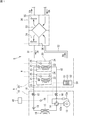
- FIG. 1 is an explanatory diagram showing a refrigerant piping system and an air system of the air conditioning ventilation system S according to the embodiment of the present disclosure.
- the air-conditioning ventilation system S is provided with a distributed air-conditioning device of a refrigerant piping system, and cools and heats the room R by performing a vapor compression refrigeration cycle operation, and ventilates the room R by a ventilation device described later. ..
- the type of indoor R which is an air-conditioned space to which the air-conditioning ventilation system S is applied, is not particularly limited in the present disclosure, and cooling and / or heating and ventilation of offices, hotels, theaters, stores, etc. Includes the space or all of the space that takes place.
- the air-conditioning ventilation system S includes an outdoor (heat source) unit 10 installed outside the indoor R, an indoor unit 20 installed in the indoor R, a ventilation device 30, and a centralized controller 40.
- the air conditioner A is composed of the outdoor unit 10 and the indoor unit 20.
- the outdoor unit 10 and the indoor unit 20 are connected by a liquid refrigerant connecting pipe 11 and a gas refrigerant connecting pipe 12.
- the ventilation device 30 and the room R are connected by an air supply (SA) duct 31.
- SA air supply
- the ventilation device 30 and the room R are connected by a return air (RA) duct 32.
- the indoor unit 20 may be installed on the floor surface, may be arranged near the ceiling, or may be arranged behind the ceiling. Although only two indoor units 20 are drawn in FIG. 1, the number of indoor units 20 may be one or three or more.
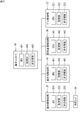
- the centralized controller 40 includes a CPU 401, a storage unit 402, and a transmission / reception unit 403. The centralized controller 40 communicates with the outdoor unit 10, the indoor unit 20, and the control unit described later of the ventilation device 30 via the transmission / reception unit 403 to control the operation of each device.
- the outdoor unit 10 and the indoor unit 20 can air-condition the indoor R by performing a well-known refrigeration cycle operation.
- a detailed description of the well-known refrigerant circuits inside each of the outdoor unit 10 and the indoor unit 20 will be omitted, and only the parts related to the present disclosure will be described below.
- the outdoor unit 10 includes a compressor 13, a four-way switching valve 14, an outdoor heat exchanger 15, an outdoor expansion valve 16, a liquid closing valve 17, a gas closing valve 18, an outdoor fan 19, and a control unit 41.
- the compressor 13 is a closed-type compressor driven by a motor for the compressor (not shown), and sucks gas refrigerant from the suction flow path 13a on the suction side of the compressor 13.
- the four-way switching valve 14 is a mechanism for switching the direction of the refrigerant flow.
- the four-way switching valve 14 connects the refrigerant pipe 13b on the discharge side of the compressor 13 and one end of the outdoor heat exchanger 15 and sucks the compressor 13.
- the suction flow path 13a on the side and the gas closing valve 18 are connected.
- the outdoor heat exchanger 15 functions as a condenser of the refrigerant compressed by the compressor 13, and the indoor heat exchanger described later functions as an evaporator of the refrigerant condensed in the outdoor heat exchanger 15. ..
- the four-way switching valve 14 connects the refrigerant pipe 13b on the discharge side of the compressor 13 and the gas closing valve 18, and also connects the suction flow path 13a and the outdoor. Connect to one end of the heat exchanger 15.
- the indoor heat exchanger functions as a condenser of the refrigerant compressed by the compressor 13, and the outdoor heat exchanger 15 functions as an evaporator of the refrigerant cooled in the indoor heat exchanger.
- the outdoor fan 19 takes in the outside air into the outdoor unit 10 and discharges the outside air heat exchanged with the refrigerant flowing through the outdoor heat exchanger 15 to the outside.
- control unit 41 includes a CPU 411, a storage unit 412, and a transmission / reception unit 413.
- the control unit 41 is communicably connected to the centralized controller 40 via the transmission / reception unit 413, and controls the operation of the compressor 13 and the like.
- the indoor unit 20 is connected to the outdoor unit 10 via the refrigerant connecting pipes 11 and 12, respectively.
- the two indoor units 20 shown in FIG. 1 both have the same outer shape and internal structure.
- Each indoor unit 20 includes an indoor expansion valve 21, an indoor heat exchanger 22, an indoor fan 23, a refrigerant sensor 24, and a control unit 25.
- the indoor fan 23 sucks the air of the indoor R into the indoor unit 20, and supplies the air exchanged with the refrigerant flowing through the indoor heat exchanger 22 to the indoor R.
- the refrigerant sensor 24 detects the concentration of the refrigerant leaked from the refrigerant pipe or the like.
- the refrigerant sensor 24 continuously or intermittently outputs an electric signal according to the detected value to the control unit 25.
- the voltage of this electric signal changes according to the concentration of the refrigerant detected by the refrigerant sensor 24.
- the position of the refrigerant sensor 24 is not particularly limited as long as the leaked refrigerant can be detected. It is desirable to place it in the vicinity of a place where leakage is likely to occur.
- the refrigerant sensor 24 may be mounted on a remote controller described later for setting, for example, room temperature or air volume, or may be arranged at an appropriate place such as a wall surface in the room. It can also be set up.
- the control unit 25 includes a CPU 251, a storage unit 252, and a transmission / reception unit 253.
- the control unit 25 is communicably connected to the centralized controller 40 via the transmission / reception unit 253.
- the control unit 25 controls the operation of the indoor fan 23 and the like in the indoor unit 20.
- the control unit 25 receives an electric signal from the refrigerant sensor 24 via the transmission / reception unit 253.
- the storage unit 252 of the control unit 25 stores a voltage value corresponding to a first predetermined value regarding the refrigerant leakage concentration.
- the first predetermined value is a value (concentration of the refrigerant) in which refrigerant leakage in the refrigerant circuit in the indoor unit 20 is assumed.
- the voltage value corresponding to the first predetermined value is calculated from the relationship between the refrigerant concentration detected by the refrigerant sensor 24 and the voltage value of the electric signal output by the refrigerant sensor 24.
- the control unit 25 determines whether or not the refrigerant concentration detected by the refrigerant sensor 24 is equal to or less than the first predetermined value, and transmits the result to the centralized controller 40. That is, the control unit 25 determines whether or not the voltage of the electric signal received from the refrigerant sensor 24 is equal to or less than the voltage value corresponding to the first predetermined value.
- the ventilation device 30 exchanges heat with the indoor R for fresh outside air OA and supplies it as an air supply SA, and discharges the return air RA from the indoor R to the outside of the machine.
- the ventilation device 30 includes a total heat exchanger 33, an air supply fan 34, an exhaust fan 35, and a control unit 36.
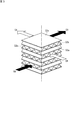
- the total heat exchanger 33 in this embodiment is an orthogonal total heat exchanger configured so that the outside air OA from the outside and the return air RA from the room R are substantially orthogonal to each other.
- the total heat exchanger 33 is a laminated stack in which a flat plate-shaped partition plate 33a having heat transfer property and moisture permeability and a corrugated plate-shaped spacing plate 33b are sequentially laminated in the vertical direction in FIG. The body.
- the spacing plate 33b has a cross section in which substantially triangular cross sections are lined up side by side when viewed from the ventilation direction (the direction indicated by the white arrow or the black arrow in FIG. 3), and flows depending on the height of the triangle. Maintain road height.
- the spacing plate 33b is angled by 90 degrees for each partition plate 33a so that a wavy cross section appears every other sheet in the vertical direction (vertical direction in FIG. 3) on a certain side surface. It is laminated. As a result, an air supply side passage (see the white arrow in FIG. 3) and an exhaust side passage (see the black arrow in FIG. 3) are formed with the heat-conducting and moisture-permeable partition plate 33a interposed therebetween. The exchange of sensible heat and latent heat is performed through.
- the ventilation device 30 in the present embodiment is a first-class ventilation device that is supplied with air by a fan and exhausted by the fan.
- a type 2 ventilation device in which air is supplied by a fan and exhaust is a natural exhaust, or a type 3 ventilation device in which exhaust is performed by a fan and air is supplied by a natural air is used. It can also be used.
- the control unit 36 includes a CPU 361, a storage unit 362, and a transmission / reception unit 363.
- the control unit 36 is communicably connected to the centralized controller 40 via the transmission / reception unit 363.
- the storage unit 362 stores data in which the set air volume in a plurality of stages is associated with the rotation speeds of the air supply fan 34 and the exhaust fan 35 corresponding to the set air volume.
- the control unit 36 controls the rotation speeds of the air supply fan 34 and the exhaust fan 35 with reference to the data stored in the storage unit 362 based on the air volume set by the user.
- the remote controller 50 is arranged in the room R.
- the remote controller 50 includes a display unit 51, a control unit 52, and an input unit 53.
- the display unit 51 displays information such as the operation mode and room temperature of the indoor unit 20, and also displays that the leakage refrigerant concentration, which will be described later, has exceeded the first predetermined value.
- the control unit 52 includes a CPU 521, a storage unit 522, and a transmission / reception unit 523.
- the control unit 52 is communicably connected to the control unit 25 of the two indoor units 20, the control unit 36 of the ventilation device 30, and the centralized controller 40 via the transmission / reception unit 523, and controls the operation of the remote controller 50. To do.
- the centralized controller 40 and each of the control units 25, 36, 41, and 52 include a computer (CPU), and the computer executes software (computer program) to realize necessary control functions.
- the software is stored in the centralized controller 40 and the storage units of the control units 25, 36, 41, and 52.
- the centralized controller 40 and each of the control units 25, 36, 41, and 52 are connected to each other by a communication line, and control coordination and information sharing are possible.
- the air conditioner A having the above-described configuration performs a cooling operation or a heating operation as follows.
- the four-way switching valve 14 is in the state shown by the solid line in FIG. In this state, the high-pressure gas refrigerant discharged from the compressor 13 is sent to the outdoor heat exchanger 15 functioning as a condenser via the four-way switching valve 14, and the outside air and heat supplied by the outdoor fan 19 are supplied. Replace and cool.
- the high-pressure refrigerant cooled and liquefied in the outdoor heat exchanger 15 is sent to each indoor unit 20 via the liquid refrigerant connecting pipe 11.
- the refrigerant sent to each indoor unit 20 is decompressed by the indoor expansion valve 21 to become a low-pressure gas-liquid two-phase state refrigerant, and heat exchanges with the air in the room R in the indoor heat exchanger 22 that functions as an evaporator. , Evaporates to become a low pressure gas refrigerant.
- the low-pressure gas refrigerant heated in the indoor heat exchanger 22 is sent to the outdoor unit 10 via the gas refrigerant connecting pipe 12, and is sucked into the compressor 13 again via the four-way switching valve 14.
- the four-way switching valve 14 is in the state shown by the broken line in FIG. In this state, the high-pressure gas refrigerant discharged from the compressor 13 is sent to each indoor unit 20 via the four-way switching valve 14 and the gas refrigerant connecting pipe 12.
- the high-pressure gas refrigerant sent to each indoor unit 20 is sent to the indoor heat exchanger 22 that functions as a condenser, exchanges heat with the air in the indoor R to be cooled, and then passes through the indoor expansion valve 21. , It is sent to the outdoor unit 10 via the liquid-refrigerant connecting pipe 11.
- the high-pressure refrigerant sent to the outdoor unit 10 is depressurized by the outdoor expansion valve 16 to become a low-pressure gas-liquid two-phase state refrigerant, and flows into the outdoor heat exchanger 15 that functions as an evaporator.
- the low-pressure gas-liquid two-phase refrigerant that has flowed into the outdoor heat exchanger 15 exchanges heat with the outside air supplied by the outdoor fan 19, is heated, and evaporates to become a low-pressure refrigerant.
- the low-pressure gas refrigerant exiting the outdoor heat exchanger 15 is sucked into the compressor 13 again via the four-way switching valve 14.
- the operation of the ventilation device 30 is performed based on a user's instruction via the remote controller 50.
- the control unit 36 Upon receiving an instruction from the user to start the operation of the ventilation device 30 at a predetermined set air volume, the control unit 36 has the predetermined set air volume stored in the storage unit and the rotation of the supply air fan 34 and the exhaust fan 35. The rotation speeds of the air supply fan 34 and the exhaust fan 35 are determined based on the data associated with the numbers.
- the control unit 36 controls the rotation of the air supply fan 34 and the exhaust fan 35 based on the determined rotation speed.
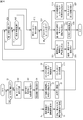
- FIG. 4 is a flowchart showing an example of processing at the time of refrigerant leakage.
- the CPU 251 of the control unit 25 of the indoor unit 20 determines whether or not the value detected from the refrigerant sensor 24 is equal to or less than the first predetermined value stored in the storage unit 252.
- the CPU 251 determines that the detected value exceeds the first predetermined value
- the CPU 251 transmits a signal to the centralized controller 40 (step S2).
- the CPU 251 determines that the detected value is equal to or less than the first predetermined value
- the CPU 251 returns to step S1.
- step S3 the CPU 401 of the centralized controller 40 instructs the control unit 41 of the outdoor unit 10 to stop the operation of the compressor 13.
- step S4 the CPU 411 of the control unit 41 stops the operation of the compressor 13.
- stopping the operation includes both stopping the operation state and maintaining the operation stop state as it is. Is.
- step S5 the CPU 401 of the centralized controller 40 instructs the control unit 36 of the ventilation device 30 to start the operation of the ventilation device 30 and maximize the ventilation air volume.
- step S6 the CPU 361 of the control unit 36 puts the ventilation device 30 into an operating state, and supplies the air supply fan 34 and the exhaust fan 35 to the maximum air volume among the set air volumes of the plurality of stages described above.
- the air fan 34 and the exhaust fan 35 are rotated at the maximum rotation speed.
- "to put into an operating state” means to maintain the state of being in the operating state as it is and to operate the one in the stopped state to be in the operating state.
- the purpose is to include.
- step S7 the CPU 401 of the centralized controller 40 instructs the control unit 25 of the indoor unit 20 to rotate the indoor fan 23.
- step S8 the CPU 251 of the control unit 25 rotates the indoor fan 23.
- step S9 the CPU 401 of the centralized controller 40 instructs the control unit 52 of the remote controller (remote controller) 50 to lock (prohibit) the input to the remote controller 50, and notifies that the refrigerant is leaking. Instruct to do.
- step S10 the CPU 521 of the control unit 52 causes a speaker (not shown) to emit an alarm sound and turns on the backlight of the display unit 51.
- step S11 the CPU 251 of the control unit 25 of the indoor unit 20 determines whether or not the value detected from the refrigerant sensor 24 is equal to or less than the first predetermined value stored in the storage unit 252. When the CPU 251 determines that the detected value is equal to or less than the first predetermined value, the CPU 251 sends a signal to the centralized controller 40 in the following step S12. On the other hand, when the CPU 251 determines that the detected value is not equal to or less than the first predetermined value, the CPU 251 proceeds to step S13.
- step S13 the CPU 251 determines whether or not the predetermined time has elapsed, and if it determines that the predetermined time has elapsed, returns to step S11. On the other hand, when the CPU 251 determines that the predetermined time has not elapsed, the CPU 251 returns to step S13.
- step S14 the CPU 401 of the centralized controller 40 determines whether or not the predetermined timing has been reached, and if it is determined that the predetermined timing has been reached, the process proceeds to step S15. Details including an example of this predetermined timing will be described later. On the other hand, when the CPU 401 determines that the predetermined timing has not been reached, the CPU 401 returns to step S14.
- step S15 the CPU 401 of the centralized controller 40 instructs the control unit 36 of the ventilation device 30 to stop the operation of the ventilation device 30.
- step S16 the CPU 361 of the control unit 36 stops the rotation of the air supply fan 34 and the exhaust fan 35.
- step S17 the CPU 401 of the centralized controller 40 instructs the control unit 25 of the indoor unit 20 to stop the rotation of the indoor fan 23.
- step S18 the CPU 251 of the control unit 25 stops the rotation of the indoor fan 23.
- step S19 the CPU 401 of the centralized controller 40 stops the control unit 52 of the remote controller (remote controller) 50 from locking (prohibiting) the input to the remote controller 50 and reporting that the refrigerant is leaking. Instruct to do.
- step S20 the CPU 521 of the control unit 52 stops locking the remote control input and issuing an alarm.
- steps S5, S7, and S9 are performed at the same time, but they may be performed in the order of the step numbers, or the order may be changed.
- steps S15, S17, and S19 may be performed in the order of the step numbers, or the order may be changed.
- the "predetermined timing” in the present disclosure indicates the time for stopping the operation of the compressor 13 and continuing the operation of the ventilation device 30 even if the refrigerant concentration exceeding the first predetermined value becomes equal to or less than the first predetermined value. Will be explained.
- the "predetermined timing” the unevenness of the refrigerant concentration in the air-conditioned space R is eliminated and the refrigerant concentration of the entire air-conditioned space R becomes equal to or less than the first predetermined value, or the unevenness of the refrigerant concentration locally occurs.
- predetermined timing As an example of this "predetermined timing", it can be a time point when the refrigerant concentration exceeding the first predetermined value drops to a second predetermined value lower than the first predetermined value.
- the refrigerant concentration in the air-conditioned space R is increased by continuing the stopped state of the compressor 13 and the operating state of the ventilation device 30 until the refrigerant concentration drops to a second predetermined value lower than the first predetermined value. Even if there is unevenness and the refrigerant concentration locally exceeds the first predetermined value, it is possible to suppress the insufficient ventilation volume of the air-conditioned space. In this case, the more the second predetermined value is set lower than the first predetermined value, the longer the time for continuing the stopped state of the compressor 13 and the operating state of the ventilation device 30 can be made, and the more reliable it is. In addition, it is possible to prevent the ventilation volume of the air-conditioned space R from becoming insufficient.
- predetermined timing it may be after a predetermined time has elapsed after the refrigerant concentration exceeding the first predetermined value becomes equal to or less than the first predetermined value.
- the "predetermined time” can be calculated based on, for example, at least one of the volume of the air-conditioned space R, the ventilation capacity of the ventilation device 30, the amount of refrigerant expected to leak into the air-conditioned space R, and the leakage rate of the refrigerant. ..
- a predetermined time can be set as follows. That is, the time calculated by dividing the total amount of refrigerant Q (kg) of the air conditioning system including the indoor unit 20 by the minimum refrigerant outflow rate vmin (kg / m 3 ) can be set as a predetermined time.
- the minimum refrigerant outflow rate mM (kg / m 3 ) is the first predetermined value (kg / m 3 ), the volume V (m 3 ) of the air-conditioned space R, and the natural ventilation frequency N of the air-conditioned space R. It can be obtained by multiplying (times / s).
- the predetermined time in this case is set on the premise that it takes the longest time for all the refrigerants to flow out when the refrigerant outflow rate is the minimum.
- the air-conditioned space R is assumed to be highly airtight, and a generally known natural ventilation frequency N (times / s) at the time of high airtightness can be adopted. Further, the volume of the air-conditioned space R can be calculated from the floor area and the ceiling height, and since the room area corresponding to the horsepower of the indoor unit 20 is determined, the total horsepower of the indoor unit 20 is used. It can also be estimated.
- the predetermined time can be set based on the ventilation capacity (ventilation air volume) of the ventilation device 30. That is, the predetermined time can be obtained by using the predicted leakage rate vcalc of the refrigerant instead of the above-mentioned vmin and dividing the total amount Q (kg) of the refrigerant by the predicted leakage rate vcalc.
- the predicted leakage rate vcalc (kg / s) is the refrigerant concentration Rsat when the refrigerant concentration is sufficiently saturated to this Qvent (m 3 / s), assuming that the ventilation capacity of the ventilation device 30 is Qvent (m 3 / s). It can be obtained by multiplying by (kg / m 3).
- the predetermined time can also be obtained by dividing the total amount of refrigerant by the leakage rate of the refrigerant.
- the refrigerant leakage rate can be determined using a generally known method. For example, the amount of refrigerant charged in the refrigerant circuit is detected a plurality of times from the information on the pressure and temperature of the refrigerant obtained by various sensors, and the amount of refrigerant charged each time is calculated. Then, the refrigerant leakage rate is estimated by dividing the difference between the refrigerant filling amounts at each time by the detection time interval, and the refrigerant filling amount is divided by the obtained refrigerant leakage rate to fill the refrigerant.
- the time until all the refrigerant leaks can be obtained.
- the time obtained in this way can be set as a predetermined time. Further, by estimating the rate of decrease in the operating current of the compressor during compressor operation as the refrigerant leakage rate and dividing the total amount of refrigerant by the estimated refrigerant leakage rate, all the filled refrigerant leaks. You can find the time to do it.
- the time obtained in this way can also be set as a predetermined time.
- predetermined timing it can be the time when the centralized controller 40 acquires the operation stop instruction.
- the operation stop instruction is, for example, the remote controller 50 in the maintenance mode in which the serviceman who confirms that the refrigerant concentration in the air-conditioned space R as a whole is equal to or less than the first predetermined value can confirm the input only by the serviceman. By switching, it is possible to input to the remote controller 50.
- the operation stop instruction input to the remote controller 50 is transmitted to the central controller 40.
- the centralized controller 40 keeps the ventilation device 30 in the operating state until the predetermined timing even if the refrigerant concentration exceeding the first predetermined value becomes equal to or less than the first predetermined value, and the air-conditioned space R It suppresses the lack of ventilation. Further, a serviceman (maintenance man) or a user at the site confirmed that the leaked refrigerant was discharged from the air-conditioned space R and the refrigerant concentration in the air-conditioned space R was generally equal to or less than the first predetermined value. Later, for example, by continuing the operation of the ventilation device 30 until the operation of the ventilation device 30 is stopped by operating the remote controller 50, it is possible to more reliably suppress the insufficient ventilation volume of the air-conditioned space R. ..
- the centralized controller 40 prohibits the operation operation by the remote controller 50 when the refrigerant concentration exceeds the first predetermined value. This makes it possible to prevent, for example, the user from operating the compressor 13 or stopping the operation of the ventilation device 30 without knowing the leakage of the refrigerant. As a result, by continuing the stopped state of the compressor 13 and the operating state of the ventilation device 30, it is possible to prevent the ventilation volume of the air-conditioned space R from becoming insufficient.
- the centralized controller 40 when the centralized controller 40 determines that the refrigerant concentration acquired from the refrigerant sensor 24 exceeds the first predetermined value, the centralized controller 40 increases the ventilation air volume of the ventilation device 30.
- the ventilation air volume can be set to be, for example, 10 to 30% higher than the ventilation air volume during normal operation.
- the centralized controller 40 when the centralized controller 40 determines that the refrigerant concentration acquired from the refrigerant sensor 24 exceeds the first predetermined value, the centralized controller 40 puts the indoor fan 23 of the indoor unit 20 into an operating state. By putting the indoor fan 23 in the operating state and diffusing the leaked refrigerant, it is possible to reduce the unevenness of the refrigerant concentration in the indoor R.
- the present disclosure is not limited to the above-described embodiment, and various modifications can be made within the scope of the claims.
- the number of outdoor units is 1, but two or more outdoor units can be adopted, and the number and arrangement of outdoor units, indoor units, and ventilation devices are particularly limited in the present disclosure.
- the air-conditioning ventilation system can be configured by appropriately selecting it. In the embodiment shown in FIG. 1, one air-conditioned space is air-conditioned by one outdoor unit, but the present disclosure is also applied to the case where one outdoor unit air-conditions a plurality of air-conditioned spaces. be able to.
- An indoor unit, a refrigerant sensor, and a remote controller that harmonize the air in the air-conditioned space are arranged in each of the plurality of air-conditioned spaces.
- the centralized controller determines that at least one of the plurality of air-conditioned spaces exceeds the first predetermined value, the centralized controller prohibits the operation operation by the remote controllers arranged in all the air-conditioned spaces.
- a user in the air-conditioned space where no refrigerant leakage may occur may operate the remote controller in order to restart the operation of the compressor of the air-conditioning device.
- the degree of leakage of the refrigerant can be reduced and the operation of the ventilation device can be prevented from being stopped. be able to.
- the ventilation device by continuing the stopped state of the compressor of the air conditioner and the operating state of the ventilation device, it is possible to suppress insufficient ventilation in all the air-conditioned spaces including the air-conditioned space where the refrigerant leaks. ..
- the centralized controller is arranged as a control unit separate from the control unit 25 of the indoor unit 20, but the control unit 25 of any of the indoor units 20 is provided with a function as the centralized controller 40. It can also be held.
- the control unit 25 (hereinafter, also referred to as the main control unit 25) having a function as the centralized controller 40 and the control unit 36 of the ventilation device 30 do not have to be directly connected so as to be communicable.
- the control unit 36 may be connected so as to be able to communicate only with another control unit 25 (sub control unit 25) connected to the main control unit 25. In this case, the control unit 36 communicates with the main control unit 25 via the sub control unit 25.
- all the control units 25 do not have to be directly communicatively connected to the main control unit 25.
- the control unit 36 of the ventilation device 30 rotates the air supply fan 34 and the exhaust fan 35 at the maximum rotation speed, but the present invention is not limited to this.
- the control unit 25 of the indoor unit 20 rotates the indoor fan 23, but it is not always necessary to rotate the indoor fan 23.
- the orthogonal total heat exchanger is arranged in the ventilation device, but a rotary total heat exchanger that recovers heat from the return air by rotating the rotor is adopted. You can also. It is also possible to omit the adoption of such a total heat exchanger in the ventilation system.
Landscapes
- Engineering & Computer Science (AREA)
- Mechanical Engineering (AREA)
- General Engineering & Computer Science (AREA)
- Chemical & Material Sciences (AREA)
- Combustion & Propulsion (AREA)
- Physics & Mathematics (AREA)
- Thermal Sciences (AREA)
- Human Computer Interaction (AREA)
- Fluid Mechanics (AREA)
- Air Conditioning Control Device (AREA)
Abstract
冷媒との熱交換により調和空気を生成する熱交換器22を有し、被空調空間Rに調和空気を送る空調装置Aと、被空調空間Rの換気をする換気装置30と、前記被空調空間Rにおける前記冷媒の濃度を検知するための冷媒センサ24と、前記空調装置A及び換気装置30の動作を制御する制御部40と、を備えた空調換気システムS。前記制御部40は、前記冷媒センサ24から取得した冷媒濃度が第1の所定値を超えていると判断すると、前記空調装置Aの圧縮機13の運転を停止状態にするとともに前記換気装置30を運転状態にする。前記制御部40は、第1の所定値を超えていた冷媒濃度が当該第1の所定値以下になったと判断すると、所定のタイミングまで、前記空調装置Aの圧縮機13の停止状態及び前記換気装置30の運転状態を継続させる。
Description
本開示は空調換気システムに関する。さらに詳しくは、空調装置及び換気装置を備えた空調換気システムに関する。
事務所ビル、ホテル等の比較的規模の大きい建物では、通常、冷風や温風を生成する空調装置と、室内に外気を供給するとともに当該室内の排気を行う換気装置とが併用されている。
空調装置から冷媒が室内に漏洩すると、酸欠等の不都合が発生する可能性がある。かかる不都合の発生を抑制するために、従来、冷媒の漏洩が検知されたときに換気装置を作動させることが提案されている(例えば、特許文献1参照)。
特許文献1記載の空調換気システムでは、空調装置と換気装置とが通信接続された状態において冷媒の漏洩が検知されると、空調装置の制御装置は、換気装置の制御装置に対し当該換気装置の運転を行うことを指令する。そして、換気装置の不調等により当該換気装置の風量不足が発生した場合には、空調装置の制御装置が当該空調装置の風量を増加させている。これにより、漏洩した冷媒が被空調空間に溜まり込んで、冷媒の排出が不十分になるのを抑制している。
しかし、被空調空間の大きさや形状、及び当該被空調空間における空調装置の位置等によっては、前述した冷媒排出のための換気装置や空調装置の運転中に、当該被空調空間の冷媒濃度にムラが生じることがある。そのため、被空調空間全体の冷媒濃度が所定値以下になっていないにもかかわらず、漏洩冷媒を検知するセンサ等により当該センサ等が配設されている箇所の冷媒濃度が前記所定値以下であると判断されると、換気装置や空調装置の運転が停止され、その結果、被空調空間の換気量が不足する恐れがある。
本開示は、被空調空間の冷媒濃度ムラにより当該被空調空間の換気量が不足するのを抑制することができる空調換気システムを提供することを目的としている。
本開示の空調換気システムは、
(1)冷媒との熱交換により調和空気を生成する熱交換器を有し、被空調空間に調和空気を送る空調装置と、
被空調空間の換気をする換気装置と、
前記被空調空間における前記冷媒の濃度を検知するための冷媒センサと、
前記空調装置及び換気装置の動作を制御する制御部と、
を備え、
前記制御部は、前記冷媒センサから取得した冷媒濃度が第1の所定値を超えていると判断すると、前記空調装置の圧縮機の運転を停止状態にするとともに前記換気装置を運転状態にし、
前記制御部は、第1の所定値を超えていた冷媒濃度が当該第1の所定値以下になったと判断すると、所定のタイミングまで、前記空調装置の圧縮機の停止状態及び前記換気装置の運転状態を継続させる。
(1)冷媒との熱交換により調和空気を生成する熱交換器を有し、被空調空間に調和空気を送る空調装置と、
被空調空間の換気をする換気装置と、
前記被空調空間における前記冷媒の濃度を検知するための冷媒センサと、
前記空調装置及び換気装置の動作を制御する制御部と、
を備え、
前記制御部は、前記冷媒センサから取得した冷媒濃度が第1の所定値を超えていると判断すると、前記空調装置の圧縮機の運転を停止状態にするとともに前記換気装置を運転状態にし、
前記制御部は、第1の所定値を超えていた冷媒濃度が当該第1の所定値以下になったと判断すると、所定のタイミングまで、前記空調装置の圧縮機の停止状態及び前記換気装置の運転状態を継続させる。
本開示の空調換気システムでは、冷媒濃度が第1の所定値を超えていると空調装置の圧縮機の運転を停止状態にするとともに前記換気装置を運転状態にする。圧縮機の運転を停止状態にすることで冷媒が漏れるのを抑制することができ、換気装置を運転状態にすることで被空調空間の換気を行い、漏洩冷媒の排出を促進させることができる。また、本開示の空調換気システムでは、第1の所定値を超えていた冷媒濃度が当該第1の所定値以下になっても、所定のタイミングまで、空調装置の圧縮機の停止状態及び換気装置の運転状態を継続させる。換言すれば、第1の所定値を超えていた、冷媒センサから取得した冷媒濃度が当該第1の所定値以下になるとすぐに空調装置の運転を始めたり換気装置の運転を止めたりすることがない。これにより、被空調空間における冷媒濃度にムラがあり、局所的に冷媒濃度が第1の所定値を超えていたとしても、所定のタイミングまで空調装置の圧縮機の停止状態及び換気装置の運転状態を継続させるので、被空調空間の換気量が不足するのを抑制することができる。なお、本明細書において、「運転を停止状態にする」とは、運転状態にあるものを停止させること、及び、運転停止状態にあるものを、その停止状態を維持することの両方を含む趣旨である。また、「運転状態にする」とは、運転状態にあるものを、その運転状態を維持すること、及び、運転停止状態にあるものを作動させて運転状態にすることの両方を含む趣旨である。
(2)前記(1)の空調換気システムにおいて、前記所定のタイミングは、前記制御部が運転停止指示を取得するときであることが望ましい。現地においてサービスマン(メンテナンスマン)やユーザーが、漏洩した冷媒が被空調空間から排出されて当該被空調空間における冷媒濃度が第1の所定値以下であることを確認した後に、例えばリモートコントローラの操作により換気装置の運転を停止させるまで当該換気装置の運転を継続させることで、被空調空間の換気量が不足するのを抑制することができる。
(3)前記(1)又は(2)の空調換気システムにおいて、前記空調換気システムは、前記空調装置及び/又は換気装置の運転を操作するためのリモートコントローラを更に備え、
前記制御部は、冷媒濃度が第1の所定値を超えた場合、前記リモートコントローラによる前記運転操作を禁止することが望ましい。これにより、例えばユーザーが冷媒の漏洩を知らずに空調装置を運転させたり、換気装置の運転を停止させたりするのを防ぐことができる。その結果、空調装置の圧縮機の停止状態及び換気装置の運転状態を継続させることで、被空調空間の換気量が不足するのを抑制することができる。
前記制御部は、冷媒濃度が第1の所定値を超えた場合、前記リモートコントローラによる前記運転操作を禁止することが望ましい。これにより、例えばユーザーが冷媒の漏洩を知らずに空調装置を運転させたり、換気装置の運転を停止させたりするのを防ぐことができる。その結果、空調装置の圧縮機の停止状態及び換気装置の運転状態を継続させることで、被空調空間の換気量が不足するのを抑制することができる。
(4)前記(3)の空調換気システムにおいて、前記空調装置は、複数の被空調空間の空気調和を行う複数の室内機と、前記複数の室内機と接続された室外機とを備え、
前記冷媒センサ及び前記リモートコントローラは、前記複数の被空調空間それぞれに配置されており、
前記制御部は、前記複数の被空調空間の少なくとも一つが前記第1の所定値を超えていると判断すると、全ての被空調空間に配置された前記リモートコントローラによる前記運転操作を禁止することが望ましい。
1つの冷媒系統で、複数の被空調空間の空気調和を行っている場合において、1つの被空調空間で冷媒漏洩が生じると、空調装置の圧縮機の運転が停止状態になるため、冷媒漏洩が生じていない被空調空間の空気調和も停止する。そのため、冷媒漏洩が生じていない被空調空間のユーザーが空調装置の圧縮機の運転を再開させるために、リモートコントローラを操作するおそれがある。前記のように、全ての被空調空間に配置されたリモートコントローラによる運転操作を禁止することにより、冷媒が漏洩する程度を小さくすることができ、また、換気装置の運転が停止されるのを防ぐことができる。その結果、空調装置の圧縮機の停止状態及び換気装置の運転状態を継続させることで、冷媒が漏洩した被空調空間を含む全ての被空調空間において換気量が不足するのを抑制することができる。
前記冷媒センサ及び前記リモートコントローラは、前記複数の被空調空間それぞれに配置されており、
前記制御部は、前記複数の被空調空間の少なくとも一つが前記第1の所定値を超えていると判断すると、全ての被空調空間に配置された前記リモートコントローラによる前記運転操作を禁止することが望ましい。
1つの冷媒系統で、複数の被空調空間の空気調和を行っている場合において、1つの被空調空間で冷媒漏洩が生じると、空調装置の圧縮機の運転が停止状態になるため、冷媒漏洩が生じていない被空調空間の空気調和も停止する。そのため、冷媒漏洩が生じていない被空調空間のユーザーが空調装置の圧縮機の運転を再開させるために、リモートコントローラを操作するおそれがある。前記のように、全ての被空調空間に配置されたリモートコントローラによる運転操作を禁止することにより、冷媒が漏洩する程度を小さくすることができ、また、換気装置の運転が停止されるのを防ぐことができる。その結果、空調装置の圧縮機の停止状態及び換気装置の運転状態を継続させることで、冷媒が漏洩した被空調空間を含む全ての被空調空間において換気量が不足するのを抑制することができる。
(5)前記(1)~(4)の空調換気システムにおいて、前記制御部は、前記冷媒センサから取得した冷媒濃度が第1の所定値を超えていると判断すると、前記換気装置の換気風量を増加させることが望ましい。換気装置の換気風量を通常運転時よりも増加させることで、被空調空間に漏洩した冷媒の、当該被空調空間からの排出を促進させることができる。
(6)前記(1)~(5)の空調換気システムにおいて、前記制御部は、前記冷媒センサから取得した冷媒濃度が第1の所定値を超えていると判断すると、前記空調装置の室内ファンを運転状態にすることが望ましい。室内ファンを運転状態にして漏洩冷媒を拡散させることで、被空調空間における冷媒濃度のムラを小さくすることができる。
(7)前記(1)~(6)の空調換気システムにおいて、前記所定のタイミングは、第1の所定値を超えていた冷媒濃度が当該第1の所定値以下になってから、所定時間経過後とすることができる。冷媒濃度が第1の所定値以下になってから所定時間経過するまで空調装置の圧縮機の停止状態及び換気装置の運転状態を継続させることで、被空調空間における冷媒濃度にムラがあり、局所的に冷媒濃度が第1の所定値を超えていたとしても、被空調空間の換気量が不足するのを抑制することができる。
(8)前記(7)の空調換気システムにおいて、前記所定時間は、前記被空調空間の容積、前記換気装置の換気能力、前記被空調空間に漏洩が予測される冷媒量及び冷媒の漏洩速度の少なくとも1つに基づき算出されるものとすることができる。かかる所定時間が経過するまで、空調装置の圧縮機の停止状態及び換気装置の運転状態を継続させることで、被空調空間における冷媒濃度にムラがあり、局所的に冷媒濃度が第1の所定値を超えていたとしても、被空調空間の換気量が不足するのを抑制することができる。
(9)前記(1)~(6)の空調換気システムにおいて、前記所定のタイミングは、前記第1の所定値を超えていた冷媒濃度が当該第1の所定値よりも低い第2の所定値まで低下した時点とすることができる。この場合、冷媒濃度が第1の所定値よりも低い第2の所定値に低下するまで空調装置の圧縮機の停止状態及び換気装置の運転状態を継続させることで、被空調空間における冷媒濃度にムラがあり、局所的に冷媒濃度が第1の所定値を超えていたとしても、被空調空間の換気量が不足するのを抑制することができる。
(10)前記(1)~(9)の空調換気システムにおいて、前記空調換気システムは、漏洩冷媒が前記第1の所定値を超えたことを表示する表示部を更に備えることが望ましい。漏洩冷媒が第1の所定値を超えたことを表示部に表示することにより、サービスマン又はユーザーは、漏洩冷媒の存在を容易に知ることができ、開口部を開放する等、漏洩冷媒を被空調空間から排出するために必要とされるアクションをとることできる。
以下、添付図面を参照しつつ、本開示の空調換気システムを詳細に説明する。なお、本開示はこれらの例示に限定されるものではなく、請求の範囲によって示され、請求の範囲と均等の意味及び範囲内でのすべての変更が含まれることが意図される。
〔空調換気システムの全体構成〕
図1は、本開示の一実施形態に係る空調換気システムSの冷媒配管系統及び空気系統を示す説明図である。空調換気システムSは、冷媒配管方式の分散型の空調装置を備えており、蒸気圧縮式の冷凍サイクル運転を行うことで室内Rを冷暖房するとともに、後述する換気装置により当該室内Rの換気を行う。
図1は、本開示の一実施形態に係る空調換気システムSの冷媒配管系統及び空気系統を示す説明図である。空調換気システムSは、冷媒配管方式の分散型の空調装置を備えており、蒸気圧縮式の冷凍サイクル運転を行うことで室内Rを冷暖房するとともに、後述する換気装置により当該室内Rの換気を行う。
空調換気システムSが適用される、被空調空間である室内Rの種類は、本開示において特に限定されるものではなく、事務所、ホテル、劇場、店舗等、冷房及び/又は暖房と換気とが行われる空間又はスペースのすべてが含まれる。空調換気システムSは、室内R外に設置される室外(熱源)機10と、室内Rに設置される室内機20と、換気装置30と、集中コントローラ40とを備えている。室外機10と室内機20とで空調装置Aが構成される。室外機10と室内機20は、液冷媒連結管11及びガス冷媒連結管12により接続されている。また、換気装置30と室内Rは、給気(SA)用ダクト31により接続されている。さらに、換気装置30と室内Rは、還気(RA)用ダクト32により接続されている。室内Rにおいて、室内機20は床面に設置してもよいし、天井付近に配設してもよいし、また、天井裏に配設してもよい。なお、図1では、2台の室内機20だけが描かれているが、室内機20の数は1台でもよいし、3台以上でもよい。
集中コントローラ40は、図2に示されるように、CPU401、記憶部402、送受信部403を備える。集中コントローラ40は、送受信部403を介して、室外機10、室内機20、及び換気装置30の後述する制御部と通信を行い、各装置の動作を制御する。
集中コントローラ40は、図2に示されるように、CPU401、記憶部402、送受信部403を備える。集中コントローラ40は、送受信部403を介して、室外機10、室内機20、及び換気装置30の後述する制御部と通信を行い、各装置の動作を制御する。
室外機10と室内機20とは、周知の冷凍サイクル運転を行うことにより、室内Rの空調を行うことができる。なお、室外機10及び室内機20のそれぞれの内部での周知の冷媒回路について、詳細な説明は省略し、本開示に関連する部分のみ以下に説明する。
室外機10は、圧縮機13、四路切換弁14、室外熱交換器15、室外膨張弁16、液閉鎖弁17、ガス閉鎖弁18、室外ファン19及び制御部41を備えている。
室外機10は、圧縮機13、四路切換弁14、室外熱交換器15、室外膨張弁16、液閉鎖弁17、ガス閉鎖弁18、室外ファン19及び制御部41を備えている。
圧縮機13は、圧縮機用のモータ(図示せず)によって駆動される密閉式圧縮機であり、圧縮機13の吸入側の吸入流路13aからガス冷媒を吸入する。
四路切換弁14は、冷媒の流れの方向を切り換えるための機構である。冷房運転時には、図1において実線で示されるように、四路切換弁14は、圧縮機13の吐出側の冷媒配管13bと室外熱交換器15の一端とを接続するとともに、圧縮機13の吸入側の吸入流路13aとガス閉鎖弁18とを接続する。これにより、室外熱交換器15が、圧縮機13によって圧縮される冷媒の凝縮器として機能し、かつ、後述する室内熱交換器が、室外熱交換器15において凝縮した冷媒の蒸発器として機能する。
また、暖房運転時には、図1において破線で示されるように、四路切換弁14は、圧縮機13の吐出側の冷媒配管13bとガス閉鎖弁18とを接続するとともに、吸入流路13aと室外熱交換器15の一端とを接続する。これにより、室内熱交換器が、圧縮機13によって圧縮された冷媒の凝縮器として機能し、かつ、室外熱交換器15が、室内熱交換器において冷却された冷媒の蒸発器として機能する。
室外ファン19は、室外機10内に外気を取り入れ、室外熱交換器15を流れる冷媒との間で熱交換された外気を屋外に排出する。
制御部41は、図2に示されるように、CPU411、記憶部412、送受信部413を備える。制御部41は、送受信部413を介して、集中コントローラ40と通信可能に接続されており、圧縮機13等の運転を制御する。
室内機20は、それぞれ冷媒連絡管11、12を介して室外機10に接続されている。図1に示される2台の室内機20は、いずれも同じ外形及び内部構造である。各室内機20は、室内膨張弁21、室内熱交換器22、室内ファン23、冷媒センサ24、及び制御部25を備えている。
室内ファン23は、室内機20内に室内Rの空気を吸入し、室内熱交換器22を流れる冷媒との間で熱交換された空気を室内Rに供給する。
冷媒センサ24は、冷媒配管等から漏洩した冷媒の濃度を検知する。冷媒センサ24は、継続的又は間欠的に制御部25に対して、検出値に応じた電気信号を出力している。この電気信号は、冷媒センサ24によって検出される冷媒の濃度に応じて電圧が変化する。冷媒センサ24の位置は、漏洩冷媒が検知可能な箇所であれば特に限定されないが、例えば、冷媒配管同士の接合点、冷媒配管の90度以上の曲げ箇所、配管厚さが薄い箇所等、冷媒の漏洩が発生しやすい箇所の近傍に配置することが望ましい。なお、冷媒センサ24は、室内機20の内部に配設する以外に、例えば室温や風量等を設定するための後述するリモートコントローラに搭載したり、また、室内の壁面等の適宜の箇所に配設したりすることもできる。
制御部25は、図2に示されるように、CPU251、記憶部252、送受信部253を備える。制御部25は、送受信部253を介して、集中コントローラ40と通信可能に接続されている。制御部25は、室内機20における室内ファン23等の動作を制御する。制御部25は、送受信部253を介して、冷媒センサ24から電気信号を受信する。制御部25の記憶部252には、冷媒漏洩濃度に関する第1の所定値に相当する電圧値が記憶されている。第1の所定値とは、室内機20内の冷媒回路における冷媒漏洩が想定される値(冷媒の濃度)である。第1の所定値に相当する電圧値は、冷媒センサ24が検出する冷媒濃度と、冷媒センサ24が出力する電気信号の電圧値との関係から算出される。制御部25は、冷媒センサ24が検出した冷媒濃度が第1の所定値以下かどうかを判断し、その結果を集中コントローラ40に送信する。すなわち、制御部25は、冷媒センサ24から受け取った電気信号の電圧が、第1の所定値に相当する電圧値以下かどうかを判断する。
換気装置30は、室内Rに新鮮な外気OAを熱交換し給気SAとして供給するとともに、当該室内Rからの還気RAを機外に排出する。換気装置30は、全熱交換器33と、給気ファン34と、排気ファン35と、制御部36とを備えている。
本実施形態における全熱交換器33は、室外からの外気OAと室内Rからの還気RAとがほぼ直交するように構成された直交型の全熱交換器である。全熱交換器33は、図3に示されるように、伝熱性及び透湿性を有する平板状の仕切板33aと、波板状の間隔板33bとを順番に図3において上下方向に積層した積層体である。間隔板33bは、通気方向(図3において白抜き矢印又は黒矢印が指す方向)から見て、ほぼ三角形状の断面が横に並んだような断面を有しており、三角形の高さにより流路高さを維持する。間隔板33bは、仕切板33aを挟んで、或る側面において上下方向(図3において上下の方向)で波形状の断面が1枚おきに現れるように、1枚ごとに90度角度を変えて積層されている。これにより、伝熱性及び透湿性を有する仕切板33aを挟んで給気側通路(図3における白抜き矢印参照)と排気側通路(図3における黒矢印参照)とが形成され、この仕切板33aを介して顕熱と潜熱の交換が行われるようになっている。本実施形態における換気装置30は、ファンにより給気され、ファンにより排気される第1種換気装置である。なお、本開示における換気装置として、給気はファンにより行い、排気は自然排気である第2種換気装置、又は、排気はファンにより行い、給気は自然給気である第3種換気装置を用いることもできる。
制御部36は、図2に示されるように、CPU361、記憶部362、送受信部363を備える。制御部36は、送受信部363を介して、集中コントローラ40と通信可能に接続されている。記憶部362には、複数段階の設定風量と、設定風量に対応した給気ファン34及び排気ファン35の回転数とが関連付けられたデータが記憶されている。制御部36は、ユーザーにより設定された風量に基づき、記憶部362に記憶されたデータを参照して、給気ファン34及び排気ファン35の回転数を制御する。
本実施形態では室内Rにリモートコントローラ50が配設されている。リモートコントローラ50は、表示部51と、制御部52と、入力部53とを備える。表示部51は、室内機20の運転モードや室温等の情報を表示するとともに、後述する漏洩冷媒濃度が第1の所定値を超えたことを表示する。制御部52は、図2に示されるように、CPU521、記憶部522、送受信部523を備える。制御部52は、送受信部523を介して、2台の室内機20の制御部25、換気装置30の制御部36及び集中コントローラ40と通信可能に接続されており、リモートコントローラ50の動作を制御する。ユーザーは、入力部53を操作することにより、温度調節や機器運転の発停等を行うことができる。
集中コントローラ40及び各制御部25、36、41、52は、コンピュータ(CPU)を含み、コンピュータがソフトウェア(コンピュータプログラム)を実行することで、必要な制御機能を実現する。ソフトウェアは、集中コントローラ40及び各制御部25、36、41、52の記憶部に格納される。集中コントローラ40及び各制御部25、36、41、52は相互に通信線により接続されており、制御の連携、及び、情報の共有が可能である。
集中コントローラ40及び各制御部25、36、41、52は、コンピュータ(CPU)を含み、コンピュータがソフトウェア(コンピュータプログラム)を実行することで、必要な制御機能を実現する。ソフトウェアは、集中コントローラ40及び各制御部25、36、41、52の記憶部に格納される。集中コントローラ40及び各制御部25、36、41、52は相互に通信線により接続されており、制御の連携、及び、情報の共有が可能である。
〔空調装置Aの基本動作〕
前述した構成を有する空調装置Aは、以下のようにして冷房運転又は暖房運転を行う。
冷房運転時には、前述したように、四路切換弁14は図1において実線で示される状態となる。この状態において、圧縮機13から吐出された高圧のガス冷媒は、四路切換弁14を経由して凝縮器として機能する室外熱交換器15に送られ、室外ファン19によって供給される外気と熱交換を行って冷却される。室外熱交換器15において冷却されて液化した高圧の冷媒は、液冷媒連絡管11を経由して各室内機20に送られる。各室内機20に送られた冷媒は、室内膨張弁21によって減圧されて低圧の気液二相状態の冷媒となり、蒸発器として機能する室内熱交換器22において室内Rの空気と熱交換をし、蒸発して低圧のガス冷媒となる。室内熱交換器22において加熱された低圧のガス冷媒は、ガス冷媒連絡管12を経由して室外機10に送られ、四路切換弁14を経由して再び圧縮機13に吸入される。
前述した構成を有する空調装置Aは、以下のようにして冷房運転又は暖房運転を行う。
冷房運転時には、前述したように、四路切換弁14は図1において実線で示される状態となる。この状態において、圧縮機13から吐出された高圧のガス冷媒は、四路切換弁14を経由して凝縮器として機能する室外熱交換器15に送られ、室外ファン19によって供給される外気と熱交換を行って冷却される。室外熱交換器15において冷却されて液化した高圧の冷媒は、液冷媒連絡管11を経由して各室内機20に送られる。各室内機20に送られた冷媒は、室内膨張弁21によって減圧されて低圧の気液二相状態の冷媒となり、蒸発器として機能する室内熱交換器22において室内Rの空気と熱交換をし、蒸発して低圧のガス冷媒となる。室内熱交換器22において加熱された低圧のガス冷媒は、ガス冷媒連絡管12を経由して室外機10に送られ、四路切換弁14を経由して再び圧縮機13に吸入される。
一方、暖房運転時には、前述したように、四路切換弁14は図1において破線で示される状態となる。この状態において、圧縮機13から吐出された高圧のガス冷媒は、四路切換弁14及びガス冷媒連絡管12を経由して各室内機20に送られる。各室内機20に送られた高圧のガス冷媒は、凝縮器として機能する室内熱交換器22に送られ、室内Rの空気と熱交換を行って冷却された後、室内膨張弁21を通過し、液冷媒連絡管11を経由して室外機10に送られる。室外機10に送られた高圧の冷媒は、室外膨張弁16によって減圧されて低圧の気液二相状態の冷媒となり、蒸発器として機能する室外熱交換器15に流入する。室外熱交換器15に流入した低圧の気液二相状態の冷媒は、室外ファン19によって供給される外気と熱交換を行って加熱され、蒸発して低圧の冷媒となる。室外熱交換器15を出た低圧のガス冷媒は、四路切換弁14を経由して再び圧縮機13に吸入される。
〔換気装置30の基本動作〕
換気装置30の運転は、リモートコントローラ50を介したユーザーの指示に基づき行われる。所定の設定風量で換気装置30の運転を開始するようにユーザーから指示を受けると、制御部36は、記憶部に記憶された、所定の設定風量と、給気ファン34及び排気ファン35の回転数とを関連付けたデータに基づき、給気ファン34及び排気ファン35の回転数を決定する。制御部36は、決定した回転数に基づき、給気ファン34及び排気ファン35の回転を制御する。
換気装置30の運転は、リモートコントローラ50を介したユーザーの指示に基づき行われる。所定の設定風量で換気装置30の運転を開始するようにユーザーから指示を受けると、制御部36は、記憶部に記憶された、所定の設定風量と、給気ファン34及び排気ファン35の回転数とを関連付けたデータに基づき、給気ファン34及び排気ファン35の回転数を決定する。制御部36は、決定した回転数に基づき、給気ファン34及び排気ファン35の回転を制御する。
〔冷媒漏洩時の空調換気システムSの制御〕
つぎに、冷媒が漏洩したときの空調換気システムSの制御について、図4を参照しつつ説明する。図4は、冷媒漏洩時の処理の一例を示すフローチャートである。
ステップS1において、室内機20の制御部25のCPU251は、冷媒センサ24からの検出値が記憶部252に記憶された第1の所定値以下であるか否かを判断する。CPU251は、前記検出値が第1の所定値を超えていると判断すると、集中コントローラ40に信号を送信する(ステップS2)。一方、CPU251は、前記検出値が第1の所定値以下であると判断すると、ステップS1に戻る。
つぎに、冷媒が漏洩したときの空調換気システムSの制御について、図4を参照しつつ説明する。図4は、冷媒漏洩時の処理の一例を示すフローチャートである。
ステップS1において、室内機20の制御部25のCPU251は、冷媒センサ24からの検出値が記憶部252に記憶された第1の所定値以下であるか否かを判断する。CPU251は、前記検出値が第1の所定値を超えていると判断すると、集中コントローラ40に信号を送信する(ステップS2)。一方、CPU251は、前記検出値が第1の所定値以下であると判断すると、ステップS1に戻る。
ステップS3において、集中コントローラ40のCPU401は、室外機10の制御部41に圧縮機13の運転を停止させるよう指示する。
ステップS4において、制御部41のCPU411は圧縮機13の運転を停止状態にする。なお、「運転を停止状態にする」とは、前述したように、運転状態にあるものを停止させること、及び、運転停止状態にあるものを、そのままの状態を維持することの両方を含む趣旨である。
ステップS4において、制御部41のCPU411は圧縮機13の運転を停止状態にする。なお、「運転を停止状態にする」とは、前述したように、運転状態にあるものを停止させること、及び、運転停止状態にあるものを、そのままの状態を維持することの両方を含む趣旨である。
ステップS5において、集中コントローラ40のCPU401は、換気装置30の制御部36に当該換気装置30の運転を開始させ、換気風量を最大風量にするよう指示する。
ステップS6において、制御部36のCPU361は、当該換気装置30を運転状態にするとともに、給気ファン34及び排気ファン35が、前述した複数段階の設定風量の内の最大風量となるように当該給気ファン34及び排気ファン35を最大回転数で回転させる。なお、「運転状態にする」とは、前述したように、運転状態にあるものを、そのままの状態を維持すること、及び、運転停止状態にあるものを作動させて運転状態にすることの両方を含む趣旨である。
ステップS6において、制御部36のCPU361は、当該換気装置30を運転状態にするとともに、給気ファン34及び排気ファン35が、前述した複数段階の設定風量の内の最大風量となるように当該給気ファン34及び排気ファン35を最大回転数で回転させる。なお、「運転状態にする」とは、前述したように、運転状態にあるものを、そのままの状態を維持すること、及び、運転停止状態にあるものを作動させて運転状態にすることの両方を含む趣旨である。
ステップS7において、集中コントローラ40のCPU401は、室内機20の制御部25に室内ファン23を回転させるよう指示する。
ステップS8において、制御部25のCPU251は、室内ファン23を回転させる。
ステップS9において、集中コントローラ40のCPU401は、リモートコントローラ(リモコン)50の制御部52に当該リモートコントローラ50への入力をロック(禁止)するよう指示するとともに、冷媒が漏洩していることを発報するよう指示する。
ステップS8において、制御部25のCPU251は、室内ファン23を回転させる。
ステップS9において、集中コントローラ40のCPU401は、リモートコントローラ(リモコン)50の制御部52に当該リモートコントローラ50への入力をロック(禁止)するよう指示するとともに、冷媒が漏洩していることを発報するよう指示する。
ステップS10において、制御部52のCPU521は、図示しないスピーカに警報音を出させるとともに、表示部51のバックライトを点灯させる。
ステップS11において、室内機20の制御部25のCPU251は、冷媒センサ24からの検出値が記憶部252に記憶された第1の所定値以下であるか否かを判断する。CPU251は、前記検出値が第1の所定値以下になったと判断した場合、続くステップS12において、集中コントローラ40に信号を送る。一方、CPU251は、前記検出値が第1の所定値以下になっていないと判断した場合、ステップS13に処理を進める。このステップS13において、CPU251は、所定時間が経過したか否かを判断し、所定時間が経過したと判断すると、ステップS11に戻る。一方、CPU251は、所定時間が経過していないと判断すると、ステップS13に戻る。
ステップS11において、室内機20の制御部25のCPU251は、冷媒センサ24からの検出値が記憶部252に記憶された第1の所定値以下であるか否かを判断する。CPU251は、前記検出値が第1の所定値以下になったと判断した場合、続くステップS12において、集中コントローラ40に信号を送る。一方、CPU251は、前記検出値が第1の所定値以下になっていないと判断した場合、ステップS13に処理を進める。このステップS13において、CPU251は、所定時間が経過したか否かを判断し、所定時間が経過したと判断すると、ステップS11に戻る。一方、CPU251は、所定時間が経過していないと判断すると、ステップS13に戻る。
ステップS14において、集中コントローラ40のCPU401は、所定のタイミングになったか否かを判断し、所定のタイミングになったと判断するとステップS15に処理を進める。この所定のタイミングの例示を含む詳細については後述する。一方、CPU401は、所定のタイミングになっていないと判断するとステップS14に戻る。
ステップS15において、集中コントローラ40のCPU401は、換気装置30の制御部36に当該換気装置30の運転を停止させるよう指示する。
ステップS16において、制御部36のCPU361は、給気ファン34及び排気ファン35の回転を停止させる。
ステップS15において、集中コントローラ40のCPU401は、換気装置30の制御部36に当該換気装置30の運転を停止させるよう指示する。
ステップS16において、制御部36のCPU361は、給気ファン34及び排気ファン35の回転を停止させる。
ステップS17において、集中コントローラ40のCPU401は、室内機20の制御部25に室内ファン23の回転を停止させるよう指示する。
ステップS18において、制御部25のCPU251は、室内ファン23の回転を停止させる。
ステップS19において、集中コントローラ40のCPU401は、リモートコントローラ(リモコン)50の制御部52に当該リモートコントローラ50への入力のロック(禁止)、及び、冷媒が漏洩していることの発報をそれぞれ停止するよう指示する。
ステップS20において、制御部52のCPU521は、リモコン入力のロック及び発報を停止させる。
なお、図4において、ステップS5、ステップS7及びステップS9は同時に行われているが、ステップの番号順に行われてもよく、順番が入れ替わってもよい。同様に、ステップS15、ステップS17及びステップS19もステップの番号順に行われてもよく、順番が入れ替わってもよい。
ステップS18において、制御部25のCPU251は、室内ファン23の回転を停止させる。
ステップS19において、集中コントローラ40のCPU401は、リモートコントローラ(リモコン)50の制御部52に当該リモートコントローラ50への入力のロック(禁止)、及び、冷媒が漏洩していることの発報をそれぞれ停止するよう指示する。
ステップS20において、制御部52のCPU521は、リモコン入力のロック及び発報を停止させる。
なお、図4において、ステップS5、ステップS7及びステップS9は同時に行われているが、ステップの番号順に行われてもよく、順番が入れ替わってもよい。同様に、ステップS15、ステップS17及びステップS19もステップの番号順に行われてもよく、順番が入れ替わってもよい。
第1の所定値を超えていた冷媒濃度が当該第1の所定値以下になっても圧縮機13の運転の停止及び換気装置30の運転を継続させる時間を示す、本開示における「所定のタイミング」について説明する。「所定のタイミング」は、被空調空間R内の冷媒濃度のムラが解消されて当該被空調空間R全体の冷媒濃度が第1の所定値以下になるか、又は、局所的に冷媒濃度のムラが残ってはいるが、全体として被空調空間R内の冷媒濃度が第1の所定値以下になっていると判断されるタイミングである。
〔所定のタイミングの第1例〕
この「所定のタイミング」の一例としては、第1の所定値を超えていた冷媒濃度が当該第1の所定値よりも低い第2の所定値まで低下した時点とすることができる。
この「所定のタイミング」の一例としては、第1の所定値を超えていた冷媒濃度が当該第1の所定値よりも低い第2の所定値まで低下した時点とすることができる。
この場合、冷媒濃度が第1の所定値よりも低い第2の所定値に低下するまで圧縮機13の停止状態及び換気装置30の運転状態を継続させることで、被空調空間Rにおける冷媒濃度にムラがあり、局所的に冷媒濃度が第1の所定値を超えていたとしても、被空調空間の換気量が不足するのを抑制することができる。この場合、第2の所定値を第1の所定値に比べて低く設定すればするほど、圧縮機13の停止状態及び換気装置30の運転状態を継続させる時間を長くすることができ、より確実に被空調空間Rの換気量が不足するのを抑制することができる。
〔所定のタイミングの第2-1例〕
この「所定のタイミング」の他の例としては、第1の所定値を超えていた冷媒濃度が当該第1の所定値以下になってから、所定時間経過後とすることができる。
前記「所定時間」は、例えば被空調空間Rの容積、換気装置30の換気能力、被空調空間Rに漏洩が予測される冷媒量及び冷媒の漏洩速度の少なくとも1つに基づき算出することができる。
この「所定のタイミング」の他の例としては、第1の所定値を超えていた冷媒濃度が当該第1の所定値以下になってから、所定時間経過後とすることができる。
前記「所定時間」は、例えば被空調空間Rの容積、換気装置30の換気能力、被空調空間Rに漏洩が予測される冷媒量及び冷媒の漏洩速度の少なくとも1つに基づき算出することができる。
例えば、以下のようにして、所定時間を設定することができる。すなわち、室内機20を含む空調システムの冷媒総量Q(kg)を最小の冷媒流出速度vmin(kg/m3)で除することで算出される時間を所定時間とすることができる。この場合、最小の冷媒流出速度vmin(kg/m3)は、第1の所定値(kg/m3)、被空調空間Rの容積V(m3)及び被空調空間Rの自然換気回数N(回/s)を乗じることで得ることができる。この場合の所定時間は、冷媒流出速度が最小のときに、すべての冷媒が流出し尽くすのに最も時間を要するとの前提のもとに設定される。最小の冷媒流出速度vmin(kg/m3)は、被空調空間Rの自然換気回数Nと冷媒流出速度が釣り合う場合であり、所定の冷媒濃度(第1の所定値)をRf(kg/m3)、被空調空間Rの容積をV(m3)とすると、
vmin=N×V×Rf
で表すことができる。なお、被空調空間Rは高気密であると仮定し、一般的に知られている高気密時の自然換気回数N(回/s)を採用することができる。また、被空調空間Rの容積は、床面積と天井高さとから算出することもできるし、また、室内機20の馬力に相当する部屋面積が定まっていることから当該室内機20の総馬力から推定することもできる。
vmin=N×V×Rf
で表すことができる。なお、被空調空間Rは高気密であると仮定し、一般的に知られている高気密時の自然換気回数N(回/s)を採用することができる。また、被空調空間Rの容積は、床面積と天井高さとから算出することもできるし、また、室内機20の馬力に相当する部屋面積が定まっていることから当該室内機20の総馬力から推定することもできる。
〔所定のタイミングの第2-2例〕
また、前記所定時間は、換気装置30の換気能力(換気風量)に基づいて設定することができる。すなわち、前述したvminに代えて、冷媒の予測漏洩速度vcalcを用い、冷媒総量Q(kg)を予測漏洩速度vcalcで除することで所定時間を求めることができる。予測漏洩速度vcalc(kg/s)は、換気装置30の換気能力をQvent(m3/s)とすると、このQvent(m3/s)に、冷媒濃度が十分にサチレーションしたときの冷媒濃度Rsat(kg/m3)を乗じることで得ることができる。ここで、サチレーションしたときとは、冷媒が漏洩し始めて被空調空間Rの冷媒濃度が一時的に上がった後、換気装置30の換気能力と冷媒流出速度とが均衡し、被空調空間Rの冷媒濃度が一定になるときをいう。以上より、所定時間T=Q/(Qvent×Rsat)により求めることができる。なお、冷媒濃度がRsatに到達するまでに流出した冷媒量は無視するものとする。無視することで、最低限必要な時間よりも長く換気を行うことになるが、安全性を向上させるという観点からは問題がない。
また、前記所定時間は、換気装置30の換気能力(換気風量)に基づいて設定することができる。すなわち、前述したvminに代えて、冷媒の予測漏洩速度vcalcを用い、冷媒総量Q(kg)を予測漏洩速度vcalcで除することで所定時間を求めることができる。予測漏洩速度vcalc(kg/s)は、換気装置30の換気能力をQvent(m3/s)とすると、このQvent(m3/s)に、冷媒濃度が十分にサチレーションしたときの冷媒濃度Rsat(kg/m3)を乗じることで得ることができる。ここで、サチレーションしたときとは、冷媒が漏洩し始めて被空調空間Rの冷媒濃度が一時的に上がった後、換気装置30の換気能力と冷媒流出速度とが均衡し、被空調空間Rの冷媒濃度が一定になるときをいう。以上より、所定時間T=Q/(Qvent×Rsat)により求めることができる。なお、冷媒濃度がRsatに到達するまでに流出した冷媒量は無視するものとする。無視することで、最低限必要な時間よりも長く換気を行うことになるが、安全性を向上させるという観点からは問題がない。
〔所定のタイミングの第2-3例〕
また、前記所定時間は、総冷媒量を冷媒の漏洩速度で除することで求めることもできる。冷媒漏洩速度は、一般に知られている手法を用いて求めることができる。例えば、各種センサにより得られる冷媒の圧力と温度の情報から、冷媒回路内に充填された冷媒充填量を検知することを複数回実施し、各回の冷媒充填量を算出する。ついで、各回の冷媒量充填量同士の差を前記検知の時間間隔で除することで、冷媒漏洩速度を推定し、冷媒充填量を得られた冷媒漏洩速度で除することで、充填されている冷媒がすべて漏洩するまでの時間を求めることができる。こうして求めた時間を所定時間とすることができる。また、圧縮機運転中の当該圧縮機の運転電流の低下速度を冷媒漏洩速度として推定し、総冷媒量を、この推定された冷媒漏洩速度で除することで、充填されている冷媒がすべて漏洩するまでの時間を求めることができる。こうして求めた時間を所定時間とすることもできる。
また、前記所定時間は、総冷媒量を冷媒の漏洩速度で除することで求めることもできる。冷媒漏洩速度は、一般に知られている手法を用いて求めることができる。例えば、各種センサにより得られる冷媒の圧力と温度の情報から、冷媒回路内に充填された冷媒充填量を検知することを複数回実施し、各回の冷媒充填量を算出する。ついで、各回の冷媒量充填量同士の差を前記検知の時間間隔で除することで、冷媒漏洩速度を推定し、冷媒充填量を得られた冷媒漏洩速度で除することで、充填されている冷媒がすべて漏洩するまでの時間を求めることができる。こうして求めた時間を所定時間とすることができる。また、圧縮機運転中の当該圧縮機の運転電流の低下速度を冷媒漏洩速度として推定し、総冷媒量を、この推定された冷媒漏洩速度で除することで、充填されている冷媒がすべて漏洩するまでの時間を求めることができる。こうして求めた時間を所定時間とすることもできる。
〔所定のタイミングの第3例〕
「所定のタイミング」の他の例としては、集中コントローラ40が運転停止指示を取得した時点とすることができる。運転停止指示は、例えば、被空調空間Rにおける冷媒濃度が全体的に第1の所定値以下になったことを確認したサービスマンが、当該サービスマンだけが入力確認できるメンテナンスモードにリモートコントローラ50を切り替えることにより当該リモートコントローラ50に入力することができる。リモートコントローラ50に入力された運転停止指示は、集中コントローラ40に送信される。
「所定のタイミング」の他の例としては、集中コントローラ40が運転停止指示を取得した時点とすることができる。運転停止指示は、例えば、被空調空間Rにおける冷媒濃度が全体的に第1の所定値以下になったことを確認したサービスマンが、当該サービスマンだけが入力確認できるメンテナンスモードにリモートコントローラ50を切り替えることにより当該リモートコントローラ50に入力することができる。リモートコントローラ50に入力された運転停止指示は、集中コントローラ40に送信される。
〔本実施形態の作用効果〕
本実施形態では、集中コントローラ40は、第1の所定値を超えていた冷媒濃度が当該第1の所定値以下になっても、所定のタイミングまで換気装置30を運転状態にして被空調空間Rの換気量が不足するのを抑制している。さらに、現地においてサービスマン(メンテナンスマン)やユーザーが、漏洩した冷媒が被空調空間Rから排出されて当該被空調空間Rにおける冷媒濃度が全体的に第1の所定値以下であることを確認した後に、例えばリモートコントローラ50の操作により換気装置30の運転を停止させるまで当該換気装置30の運転を継続させることで、被空調空間Rの換気量が不足するのをより確実に抑制することができる。
本実施形態では、集中コントローラ40は、第1の所定値を超えていた冷媒濃度が当該第1の所定値以下になっても、所定のタイミングまで換気装置30を運転状態にして被空調空間Rの換気量が不足するのを抑制している。さらに、現地においてサービスマン(メンテナンスマン)やユーザーが、漏洩した冷媒が被空調空間Rから排出されて当該被空調空間Rにおける冷媒濃度が全体的に第1の所定値以下であることを確認した後に、例えばリモートコントローラ50の操作により換気装置30の運転を停止させるまで当該換気装置30の運転を継続させることで、被空調空間Rの換気量が不足するのをより確実に抑制することができる。
また、本実施形態では、集中コントローラ40は、冷媒濃度が第1の所定値を超えた場合、リモートコントローラ50による運転操作を禁止している。これにより、例えばユーザーが冷媒の漏洩を知らずに圧縮機13を運転させたり、換気装置30の運転を停止させたりするのを防ぐことができる。その結果、圧縮機13の停止状態及び換気装置30の運転状態を継続させることで、被空調空間Rの換気量が不足するのを抑制することができる。
また、本実施形態では、集中コントローラ40は、冷媒センサ24から取得した冷媒濃度が第1の所定値を超えていると判断すると、前記換気装置30の換気風量を増加させている。具体的に、通常運転時の換気風量よりも、例えば10~30%多い換気風量とすることができる。換気装置30の換気風量を通常運転時よりも増加させることで、室内Rに漏洩した冷媒の、当該室内Rからの排出を促進させることができる。
また、本実施形態では、集中コントローラ40は、冷媒センサ24から取得した冷媒濃度が第1の所定値を超えていると判断すると、室内機20の室内ファン23を運転状態にする。室内ファン23を運転状態にして漏洩冷媒を拡散させることで、室内Rにおける冷媒濃度のムラを小さくすることができる。
〔その他の変形例〕
本開示は前述した実施形態に限定されるものではなく、請求の範囲内において種々の変更が可能である。
例えば前述した実施形態では、室外機の数は1であるが、2台以上の室外機を採用することができ、室外機、室内機及び換気装置の数及び配置は、本開示において特に限定されるものではなく、適宜選定して空調換気システムを構成することができる。図1に示される実施形態では、1つの被空調空間を1台の室外機で空調しているが、1台の室外機で複数の被空調空間の空調を行う場合にも本開示を適用することができる。複数の被空調空間には、それぞれ当該被空調空間の空気調和を行う室内機、冷媒センサ及びリモートコントローラが配設されている。この場合、集中コントローラは、複数の被空調空間の少なくとも一つが第1の所定値を超えていると判断すると、全ての被空調空間に配置されたリモートコントローラによる運転操作を禁止する。1つの冷媒系統で、複数の被空調空間の空気調和を行っている場合において、1つの被空調空間で冷媒漏洩が生じると、空調装置の圧縮機の運転が停止状態になるため、冷媒漏洩が生じていない被空調空間の空気調和も停止する。そのため、冷媒漏洩が生じていない被空調空間のユーザーが空調装置の圧縮機の運転を再開させるために、リモートコントローラを操作するおそれがある。前記のように、全ての被空調空間に配置されたリモートコントローラによる運転操作を禁止することにより、冷媒が漏洩する程度を小さくすることができ、また、換気装置の運転が停止されるのを防ぐことができる。その結果、空調装置の圧縮機の停止状態及び換気装置の運転状態を継続させることで、冷媒が漏洩した被空調空間を含む全ての被空調空間において換気量が不足するのを抑制することができる。
本開示は前述した実施形態に限定されるものではなく、請求の範囲内において種々の変更が可能である。
例えば前述した実施形態では、室外機の数は1であるが、2台以上の室外機を採用することができ、室外機、室内機及び換気装置の数及び配置は、本開示において特に限定されるものではなく、適宜選定して空調換気システムを構成することができる。図1に示される実施形態では、1つの被空調空間を1台の室外機で空調しているが、1台の室外機で複数の被空調空間の空調を行う場合にも本開示を適用することができる。複数の被空調空間には、それぞれ当該被空調空間の空気調和を行う室内機、冷媒センサ及びリモートコントローラが配設されている。この場合、集中コントローラは、複数の被空調空間の少なくとも一つが第1の所定値を超えていると判断すると、全ての被空調空間に配置されたリモートコントローラによる運転操作を禁止する。1つの冷媒系統で、複数の被空調空間の空気調和を行っている場合において、1つの被空調空間で冷媒漏洩が生じると、空調装置の圧縮機の運転が停止状態になるため、冷媒漏洩が生じていない被空調空間の空気調和も停止する。そのため、冷媒漏洩が生じていない被空調空間のユーザーが空調装置の圧縮機の運転を再開させるために、リモートコントローラを操作するおそれがある。前記のように、全ての被空調空間に配置されたリモートコントローラによる運転操作を禁止することにより、冷媒が漏洩する程度を小さくすることができ、また、換気装置の運転が停止されるのを防ぐことができる。その結果、空調装置の圧縮機の停止状態及び換気装置の運転状態を継続させることで、冷媒が漏洩した被空調空間を含む全ての被空調空間において換気量が不足するのを抑制することができる。
また、前述した実施形態では、室内機20の制御部25とは別の制御部として集中コントローラを配設しているが、いずれかの室内機20の制御部25に集中コントローラ40としての機能をもたせることもできる。この場合、集中コントローラ40としての機能を有する制御部25(以下、メイン制御部25ともいう)と、換気装置30の制御部36とは、直接通信可能に接続されていなくてもよい。制御部36は、メイン制御部25と接続された他の制御部25(サブ制御部25)とのみ通信可能に接続されていてもよい。この場合、制御部36は、サブ制御部25を介して、メイン制御部25と通信を行う。室内機20が3つ以上の場合も同様に、全ての制御部25がメイン制御部25と直接通信可能に接続されていなくてもよい。
また、前述した実施形態では、冷媒漏洩時、換気装置30の制御部36は、給気ファン34及び排気ファン35を最大回転数で回転させているが、これに限られない。
また、前述した実施形態では、冷媒漏洩時、室内機20の制御部25は、室内ファン23を回転させているが、必ずしも回転させる必要はない。
また、前述した実施形態では、換気装置内に直交型の全熱交換器を配設しているが、ロータの回転により還気からの熱回収を行う回転型の全熱交換器を採用することもできる。また、換気装置における、かかる全熱交換器の採用を省略することもできる。
また、前述した実施形態では、冷媒漏洩時、室内機20の制御部25は、室内ファン23を回転させているが、必ずしも回転させる必要はない。
また、前述した実施形態では、換気装置内に直交型の全熱交換器を配設しているが、ロータの回転により還気からの熱回収を行う回転型の全熱交換器を採用することもできる。また、換気装置における、かかる全熱交換器の採用を省略することもできる。
10 : 室外機
11 : 液冷媒配管
12 : ガス冷媒配管
13 : 圧縮機
14 : 四路切換弁
15 : 室外熱交換器
16 : 室外膨張弁
17 : 液閉鎖弁
18 : ガス閉鎖弁
19 : 室外ファン
20 : 室内機
21 : 室内膨張弁
22 : 室内熱交換器
23 : 室内ファン
24 : 冷媒センサ
25 : 制御部
30 : 換気装置
31 : 給気ダクト
32 : 還気ダクト
33 : 全熱交換器
34 : 給気ファン
35 : 排気ファン
36 : 制御部
40 : 集中コントローラ
41 : 制御部
50 : リモートコントローラ
51 : 表示部
52 : 制御部
53 : 入力部
251 : CPU
252 : 記憶部
253 : 送受信部
361 : CPU
362 : 記憶部
363 : 送受信部
401 : CPU
402 : 記憶部
403 : 送受信部
411 : CPU
412 : 記憶部
413 : 送受信部
521 : CPU
522 : 記憶部
523 : 送受信部
A : 空調装置
R : 室内(被空調空間)
S : 空調換気システム
11 : 液冷媒配管
12 : ガス冷媒配管
13 : 圧縮機
14 : 四路切換弁
15 : 室外熱交換器
16 : 室外膨張弁
17 : 液閉鎖弁
18 : ガス閉鎖弁
19 : 室外ファン
20 : 室内機
21 : 室内膨張弁
22 : 室内熱交換器
23 : 室内ファン
24 : 冷媒センサ
25 : 制御部
30 : 換気装置
31 : 給気ダクト
32 : 還気ダクト
33 : 全熱交換器
34 : 給気ファン
35 : 排気ファン
36 : 制御部
40 : 集中コントローラ
41 : 制御部
50 : リモートコントローラ
51 : 表示部
52 : 制御部
53 : 入力部
251 : CPU
252 : 記憶部
253 : 送受信部
361 : CPU
362 : 記憶部
363 : 送受信部
401 : CPU
402 : 記憶部
403 : 送受信部
411 : CPU
412 : 記憶部
413 : 送受信部
521 : CPU
522 : 記憶部
523 : 送受信部
A : 空調装置
R : 室内(被空調空間)
S : 空調換気システム
Claims (10)
- 冷媒との熱交換により調和空気を生成する熱交換器(22)を有し、被空調空間(R)に調和空気を送る空調装置(A)と、
被空調空間(R)の換気をする換気装置(30)と、
前記被空調空間(R)における前記冷媒の濃度を検知するための冷媒センサ(24)と、
前記空調装置(A)及び換気装置(30)の動作を制御する制御部(40)と、
を備え、
前記制御部(40)は、前記冷媒センサ(24)から取得した冷媒濃度が第1の所定値を超えていると判断すると、前記空調装置(A)の圧縮機(13)の運転を停止状態にするとともに前記換気装置(30)を運転状態にし、
前記制御部(40)は、第1の所定値を超えていた冷媒濃度が当該第1の所定値以下になったと判断すると、所定のタイミングまで、前記空調装置(A)の圧縮機(13)の停止状態及び前記換気装置(30)の運転状態を継続させる、空調換気システム(S)。 - 前記所定のタイミングは、前記制御部(40)が運転停止指示を取得するときである、請求項1に記載の空調換気システム(S)。
- 前記空調換気システム(S)は、前記空調装置(A)及び/又は換気装置(30)の運転を操作するためのリモートコントローラ(50)を更に備え、
前記制御部(40)は、冷媒濃度が第1の所定値を超えた場合、前記リモートコントローラ(50)による前記運転操作を禁止する、請求項1又は請求項2に記載の空調換気システム(S)。 - 前記空調装置(A)は、複数の被空調空間(R)の空気調和を行う複数の室内機(20)と、前記複数の室内機(20)と接続された室外機(10)とを備え、
前記冷媒センサ(24)及び前記リモートコントローラ(50)は、前記複数の被空調空間(R)それぞれに配置されており、
前記制御部(40)は、前記複数の被空調空間(R)の少なくとも一つが前記第1の所定値を超えていると判断すると、全ての被空調空間(R)に配置された前記リモートコントローラ(50)による前記運転操作を禁止する、請求項3記載の空調換気システム(S)。 - 前記制御部(40)は、前記冷媒センサ(24)から取得した冷媒濃度が第1の所定値を超えていると判断すると、前記換気装置(30)の換気風量を増加させる、請求項1~4のいずれか一項に記載の空調換気システム(S)。
- 前記制御部(40)は、前記冷媒センサ(24)から取得した冷媒濃度が第1の所定値を超えていると判断すると、前記空調装置(A)の室内ファン(23)を運転状態にする、請求項1~5のいずれか一項に記載の空調換気システム(S)。
- 前記所定のタイミングは、第1の所定値を超えていた冷媒濃度が当該第1の所定値以下になってから、所定時間経過後である、請求項1~6のいずれか一項に記載の空調換気システム(S)。
- 前記所定時間は、前記被空調空間(R)の容積、前記換気装置(30)の換気能力、前記被空調空間(R)に漏洩が予測される冷媒量及び冷媒の漏洩速度の少なくとも1つに基づき算出される、請求項7に記載の空調換気システム(S)。
- 前記所定のタイミングは、前記第1の所定値を超えていた冷媒濃度が当該第1の所定値よりも低い第2の所定値まで低下した時点である、請求項1~6のいずれか一項に記載の空調換気システム(S)。
- 前記空調換気システム(S)は、漏洩冷媒が前記第1の所定値を超えたことを表示する表示部(51)を更に備える、請求項1~9のいずれか一項に記載の空調換気システム(S)。
Priority Applications (3)
| Application Number | Priority Date | Filing Date | Title |
|---|---|---|---|
| CN202080068482.8A CN114585862B (zh) | 2019-09-30 | 2020-09-02 | 空调换气系统 |
| EP20871126.7A EP4040088B1 (en) | 2019-09-30 | 2020-09-02 | Air conditioning and ventilation system |
| US17/688,186 US11885517B2 (en) | 2019-09-30 | 2022-03-07 | Air conditioning and ventilating system that enhance ventilation in response to a refrigerant leakage |
Applications Claiming Priority (2)
| Application Number | Priority Date | Filing Date | Title |
|---|---|---|---|
| JP2019178824A JP6978696B2 (ja) | 2019-09-30 | 2019-09-30 | 空調換気システム |
| JP2019-178824 | 2019-09-30 |
Related Child Applications (1)
| Application Number | Title | Priority Date | Filing Date |
|---|---|---|---|
| US17/688,186 Continuation US11885517B2 (en) | 2019-09-30 | 2022-03-07 | Air conditioning and ventilating system that enhance ventilation in response to a refrigerant leakage |
Publications (1)
| Publication Number | Publication Date |
|---|---|
| WO2021065303A1 true WO2021065303A1 (ja) | 2021-04-08 |
Family
ID=75270398
Family Applications (1)
| Application Number | Title | Priority Date | Filing Date |
|---|---|---|---|
| PCT/JP2020/033174 Ceased WO2021065303A1 (ja) | 2019-09-30 | 2020-09-02 | 空調換気システム |
Country Status (5)
| Country | Link |
|---|---|
| US (1) | US11885517B2 (ja) |
| EP (1) | EP4040088B1 (ja) |
| JP (1) | JP6978696B2 (ja) |
| CN (1) | CN114585862B (ja) |
| WO (1) | WO2021065303A1 (ja) |
Families Citing this family (8)
| Publication number | Priority date | Publication date | Assignee | Title |
|---|---|---|---|---|
| US11231198B2 (en) | 2019-09-05 | 2022-01-25 | Trane International Inc. | Systems and methods for refrigerant leak detection in a climate control system |
| JP7157722B2 (ja) * | 2019-09-30 | 2022-10-20 | ダイキン工業株式会社 | 空調換気システム |
| AU2021437814A1 (en) | 2021-03-29 | 2023-10-05 | Panasonic Intellectual Property Corporation Of America | Communication device and communication method |
| US12487008B2 (en) | 2022-01-14 | 2025-12-02 | Trane International Inc. | Method of commissioning an HVAC system |
| JP7648913B2 (ja) * | 2022-03-31 | 2025-03-19 | ダイキン工業株式会社 | 空気調和装置 |
| US12117191B2 (en) | 2022-06-24 | 2024-10-15 | Trane International Inc. | Climate control system with improved leak detector |
| JP2024116685A (ja) * | 2023-02-16 | 2024-08-28 | 三菱重工サーマルシステムズ株式会社 | 空調機および制御方法 |
| WO2025169265A1 (ja) * | 2024-02-05 | 2025-08-14 | 三菱電機株式会社 | 室内機、空気調和器、制御方法、及びプログラム |
Citations (8)
| Publication number | Priority date | Publication date | Assignee | Title |
|---|---|---|---|---|
| JP2011106697A (ja) * | 2009-11-13 | 2011-06-02 | Mitsubishi Electric Corp | 空調室内機 |
| JP2012013339A (ja) * | 2010-07-02 | 2012-01-19 | Hitachi Appliances Inc | 空気調和機 |
| WO2012049710A1 (ja) * | 2010-10-14 | 2012-04-19 | 三菱電機株式会社 | 室外機および空気調和装置 |
| JP2015094515A (ja) * | 2013-11-12 | 2015-05-18 | ダイキン工業株式会社 | 室内機 |
| JP2016211762A (ja) * | 2015-04-30 | 2016-12-15 | ダイキン工業株式会社 | 空調換気システム |
| JP2016211826A (ja) * | 2015-05-13 | 2016-12-15 | ダイキン工業株式会社 | 空調換気システム |
| JP2016223643A (ja) | 2015-05-27 | 2016-12-28 | ダイキン工業株式会社 | 空調換気システム |
| JP2018091550A (ja) * | 2016-12-02 | 2018-06-14 | 三菱電機株式会社 | 空気調和機 |
Family Cites Families (10)
| Publication number | Priority date | Publication date | Assignee | Title |
|---|---|---|---|---|
| JP3708405B2 (ja) | 2000-06-19 | 2005-10-19 | 三菱電機株式会社 | 可燃性冷媒使用の家電機器 |
| JP4799563B2 (ja) | 2005-10-25 | 2011-10-26 | 三菱電機株式会社 | 空気調和装置、空気調和装置の冷媒充填方法、空気調和装置の冷媒充填状態判定方法、並びに空気調和装置の冷媒充填・配管洗浄方法 |
| US9879871B2 (en) * | 2014-06-13 | 2018-01-30 | Lennox Industries Inc. | HVAC systems and methods with refrigerant leak detection |
| KR102095757B1 (ko) | 2015-02-18 | 2020-04-01 | 다이킨 고교 가부시키가이샤 | 공조 시스템 |
| WO2016151641A1 (ja) * | 2015-03-26 | 2016-09-29 | 三菱電機株式会社 | 空気調和機の室内機 |
| JPWO2016157538A1 (ja) * | 2015-04-03 | 2017-04-27 | 三菱電機株式会社 | 冷凍サイクル装置 |
| JP6497195B2 (ja) * | 2015-04-28 | 2019-04-10 | ダイキン工業株式会社 | 空調装置 |
| GB2554267B (en) * | 2015-06-30 | 2020-12-16 | Mitsubishi Electric Corp | Refrigerant leakage detection system |
| WO2017068686A1 (ja) | 2015-10-22 | 2017-04-27 | 三菱電機株式会社 | 冷凍サイクル装置 |
| JP6955311B2 (ja) | 2017-03-22 | 2021-10-27 | 丸八空調工業株式会社 | 冷媒漏れ対処方法 |
-
2019
- 2019-09-30 JP JP2019178824A patent/JP6978696B2/ja active Active
-
2020
- 2020-09-02 CN CN202080068482.8A patent/CN114585862B/zh active Active
- 2020-09-02 WO PCT/JP2020/033174 patent/WO2021065303A1/ja not_active Ceased
- 2020-09-02 EP EP20871126.7A patent/EP4040088B1/en active Active
-
2022
- 2022-03-07 US US17/688,186 patent/US11885517B2/en active Active
Patent Citations (8)
| Publication number | Priority date | Publication date | Assignee | Title |
|---|---|---|---|---|
| JP2011106697A (ja) * | 2009-11-13 | 2011-06-02 | Mitsubishi Electric Corp | 空調室内機 |
| JP2012013339A (ja) * | 2010-07-02 | 2012-01-19 | Hitachi Appliances Inc | 空気調和機 |
| WO2012049710A1 (ja) * | 2010-10-14 | 2012-04-19 | 三菱電機株式会社 | 室外機および空気調和装置 |
| JP2015094515A (ja) * | 2013-11-12 | 2015-05-18 | ダイキン工業株式会社 | 室内機 |
| JP2016211762A (ja) * | 2015-04-30 | 2016-12-15 | ダイキン工業株式会社 | 空調換気システム |
| JP2016211826A (ja) * | 2015-05-13 | 2016-12-15 | ダイキン工業株式会社 | 空調換気システム |
| JP2016223643A (ja) | 2015-05-27 | 2016-12-28 | ダイキン工業株式会社 | 空調換気システム |
| JP2018091550A (ja) * | 2016-12-02 | 2018-06-14 | 三菱電機株式会社 | 空気調和機 |
Non-Patent Citations (1)
| Title |
|---|
| See also references of EP4040088A4 |
Also Published As
| Publication number | Publication date |
|---|---|
| EP4040088B1 (en) | 2024-06-05 |
| JP2021055903A (ja) | 2021-04-08 |
| EP4040088A4 (en) | 2022-10-26 |
| JP6978696B2 (ja) | 2021-12-08 |
| EP4040088A1 (en) | 2022-08-10 |
| CN114585862A (zh) | 2022-06-03 |
| CN114585862B (zh) | 2024-01-16 |
| US20220186960A1 (en) | 2022-06-16 |
| US11885517B2 (en) | 2024-01-30 |
Similar Documents
| Publication | Publication Date | Title |
|---|---|---|
| JP6978696B2 (ja) | 空調換気システム | |
| US11927355B2 (en) | Air conditioning and ventilating system | |
| JP5236009B2 (ja) | 空気調和装置 | |
| US20210348820A1 (en) | Heat load processing system | |
| US20210356154A1 (en) | Heat load processing system | |
| CN113167484A (zh) | 空气调节器 | |
| JP6572628B2 (ja) | 空調換気システム | |
| JP2016151395A (ja) | 空気調和装置 | |
| KR20090044785A (ko) | 냉매 누설 감지 시스템 및 그 제어방법 | |
| CN104813110A (zh) | 空调装置 | |
| JP4422935B2 (ja) | 空調システム | |
| JP2020183829A (ja) | 空調システム及び補助ファン | |
| JP4173880B2 (ja) | 空気調和システムの除湿制御方法 | |
| JP2010007996A (ja) | 空気調和装置の試運転方法および空気調和装置 | |
| JP2018096593A (ja) | 空調システム | |
| WO2023002522A1 (ja) | 空気調和装置及び空気調和装置の設置方法 | |
| JP2020183838A (ja) | 空調システム | |
| JP7397275B2 (ja) | 空調システム | |
| JP7657096B2 (ja) | 冷凍サイクル装置および冷媒漏洩判定システム | |
| JP7032672B2 (ja) | 冷媒回路装置評価システム |
Legal Events
| Date | Code | Title | Description |
|---|---|---|---|
| 121 | Ep: the epo has been informed by wipo that ep was designated in this application |
Ref document number: 20871126 Country of ref document: EP Kind code of ref document: A1 |
|
| NENP | Non-entry into the national phase |
Ref country code: DE |
|
| ENP | Entry into the national phase |
Ref document number: 2020871126 Country of ref document: EP Effective date: 20220502 |