WO2021065521A1 - クラッチ装置 - Google Patents
クラッチ装置 Download PDFInfo
- Publication number
- WO2021065521A1 WO2021065521A1 PCT/JP2020/035139 JP2020035139W WO2021065521A1 WO 2021065521 A1 WO2021065521 A1 WO 2021065521A1 JP 2020035139 W JP2020035139 W JP 2020035139W WO 2021065521 A1 WO2021065521 A1 WO 2021065521A1
- Authority
- WO
- WIPO (PCT)
- Prior art keywords
- clutch
- side plate
- pressing portion
- rotating body
- plate
- Prior art date
- Legal status (The legal status is an assumption and is not a legal conclusion. Google has not performed a legal analysis and makes no representation as to the accuracy of the status listed.)
- Ceased
Links
Images

Classifications
-
- F—MECHANICAL ENGINEERING; LIGHTING; HEATING; WEAPONS; BLASTING
- F16—ENGINEERING ELEMENTS AND UNITS; GENERAL MEASURES FOR PRODUCING AND MAINTAINING EFFECTIVE FUNCTIONING OF MACHINES OR INSTALLATIONS; THERMAL INSULATION IN GENERAL
- F16F—SPRINGS; SHOCK-ABSORBERS; MEANS FOR DAMPING VIBRATION
- F16F15/00—Suppression of vibrations in systems; Means or arrangements for avoiding or reducing out-of-balance forces, e.g. due to motion
- F16F15/10—Suppression of vibrations in rotating systems by making use of members moving with the system
- F16F15/12—Suppression of vibrations in rotating systems by making use of members moving with the system using elastic members or friction-damping members, e.g. between a rotating shaft and a gyratory mass mounted thereon
- F16F15/121—Suppression of vibrations in rotating systems by making use of members moving with the system using elastic members or friction-damping members, e.g. between a rotating shaft and a gyratory mass mounted thereon using springs as elastic members, e.g. metallic springs
- F16F15/123—Wound springs
-
- F—MECHANICAL ENGINEERING; LIGHTING; HEATING; WEAPONS; BLASTING
- F16—ENGINEERING ELEMENTS AND UNITS; GENERAL MEASURES FOR PRODUCING AND MAINTAINING EFFECTIVE FUNCTIONING OF MACHINES OR INSTALLATIONS; THERMAL INSULATION IN GENERAL
- F16D—COUPLINGS FOR TRANSMITTING ROTATION; CLUTCHES; BRAKES
- F16D13/00—Friction clutches
- F16D13/22—Friction clutches with axially-movable clutching members
- F16D13/38—Friction clutches with axially-movable clutching members with flat clutching surfaces, e.g. discs
- F16D13/52—Clutches with multiple lamellae ; Clutches in which three or more axially moveable members are fixed alternately to the shafts to be coupled and are pressed from one side towards an axially-located member
- F16D13/54—Clutches with multiple lamellae ; Clutches in which three or more axially moveable members are fixed alternately to the shafts to be coupled and are pressed from one side towards an axially-located member with means for increasing the effective force between the actuating sleeve or equivalent member and the pressure member
- F16D13/56—Clutches with multiple lamellae ; Clutches in which three or more axially moveable members are fixed alternately to the shafts to be coupled and are pressed from one side towards an axially-located member with means for increasing the effective force between the actuating sleeve or equivalent member and the pressure member in which the clutching pressure is produced by springs only
-
- F—MECHANICAL ENGINEERING; LIGHTING; HEATING; WEAPONS; BLASTING
- F16—ENGINEERING ELEMENTS AND UNITS; GENERAL MEASURES FOR PRODUCING AND MAINTAINING EFFECTIVE FUNCTIONING OF MACHINES OR INSTALLATIONS; THERMAL INSULATION IN GENERAL
- F16D—COUPLINGS FOR TRANSMITTING ROTATION; CLUTCHES; BRAKES
- F16D2300/00—Special features for couplings or clutches
- F16D2300/12—Mounting or assembling
Definitions
- the present invention relates to a clutch device that transmits and shuts off the rotational driving force of a driving shaft that is rotationally driven by a prime mover to a driven shaft that drives a driven body.
- a clutch device is arranged between a prime mover such as an engine and a driven body such as a wheel to transmit or shut off the rotational driving force of the prime mover to the driven body. It is used.
- a clutch device a plurality of first friction plates rotated by a rotational driving force of a prime mover and a plurality of second friction plates connected to a driven body are arranged to face each other, and these first friction plates and a second friction plate are arranged.
- the rotational driving force can be arbitrarily transmitted or cut off by bringing the friction plate into close contact with the friction plate.
- the rotational driving force of the prime mover is elastically clutched between the driven gear as an input rotating body for inputting the rotational driving force of the prime mover and the clutch outer that holds the plurality of first friction plates.
- a clutch device including a damper mechanism that transmits to the outer is disclosed.
- the damper mechanism is mainly configured to include a damper spring, a sliding plate, a holding plate, a rivet, and a diaphragm spring, respectively.
- the present invention has been made to address the above problems, and an object of the present invention is to provide a clutch device capable of reducing vibration generated when a rotational driving force is transmitted from a prime mover.
- the feature of the present invention is a clutch device that transmits or shuts off the rotational driving force of the driving shaft to the driven shaft, an input rotating body that is rotationally driven together with the driving shaft by the rotational driving of the driving shaft, and a driven shaft.
- a clutch outer formed in a bottomed tubular shape that is arranged opposite to a second friction plate that is rotationally driven together with a shaft and holds a first friction plate that is rotationally driven by the rotational drive of an input rotating body, and an input rotating body and a clutch outer. It is equipped with a damper mechanism that transmits the rotational driving force of the input rotating body to the clutch outer while allowing the relative rotation of the damper mechanism.
- the damper mechanism is formed in a flat plate annular shape and is arranged between the input rotating body and the clutch outer.
- the outer side plate faces the inner peripheral side pressing portion pressed against the input rotating body and the clutch outer at a position facing the ring spring on the inner peripheral side, and the ring spring on the outer peripheral side. It is intended to have an input rotating body and an outer peripheral side pressing portion pressed against the clutch outer at the respective positions.
- ring springs for pressing the outer side plate against the input rotating body are provided on the inner peripheral side and the outer peripheral side in the radial direction of the outer side plate, respectively, and each of these is provided.
- An outer side plate having an inner peripheral side pressing portion and an outer peripheral side pressing portion pressed against the input rotating body and the clutch outer is provided at a position facing the ring spring.
- the clutch device can reduce the vibration generated when the rotational driving force from the prime mover is transmitted by smoothly transmitting the rotational driving force of the input rotating body to the clutch outer.
- the outer side plate has a total area of the inner peripheral side pressing portion and the outer peripheral side pressing portion in which the outer side plate contacts the input rotating body and the clutch outer, respectively. It is at least 40% or more of the area.
- the clutch device can equalize the contact surface pressure on the input rotating body of the outer side plate and the contact surface with the clutch outer, and from the ring spring.
- the non-uniformity of the load is reduced, and the vibration generated when the rotational driving force is transmitted from the prime mover can be reduced.
- the outer side plate has a radial pressing portion in which the inner peripheral side pressing portion and the outer peripheral side pressing portion are continuously connected in the radial direction of the outer side plate. It is in what you are doing.
- the outer side plate is subjected to radial pressing in which the inner peripheral side pressing portion and the outer peripheral side pressing portion are continuously connected in the radial direction of the outer side plate. Since the portion is provided, the load from the ring spring can be applied along the radial direction of the outer side plate, and the non-uniformity of the load from the ring spring can be reduced more effectively.
- the outer side plate is the input rotating body and the clutch outer, and the total area of the inner peripheral side pressing portion, the outer peripheral side pressing portion and the radial pressing portion is input to the outer side plate. It is at least 70% or more of the total area in contact with each other.
- the clutch device can further equalize the contact surface pressure on the input rotating body of the outer side plate and the contact surface with the clutch outer, and the ring spring. It is possible to reduce the non-uniformity of the load from the engine and reduce the vibration generated when the rotational driving force is transmitted from the prime mover.
- the radial pressing portion is formed wider than the widths of the inner peripheral side pressing portion and the outer peripheral side pressing portion.
- the radial pressing portions have different widths in the circumferential direction of the two radial pressing portions adjacent to each other in the circumferential direction of the outer side plate. is there.
- the radial pressing portions have different circumferential widths in the two radial pressing portions adjacent to each other in the circumferential direction of the outer side plate. Therefore, the friction characteristics of each radial pressing portion in the circumferential direction and the behavior of the lubricating oil are changed to suppress the monotonous or unbalanced action of the friction characteristics when the outer side plate is sliding or stationary. Can be improved as a whole outer side plate.
- Another feature of the present invention is that, in the clutch device, a plurality of connecting pins are provided along the circumferential direction of the outer side plate, and a plurality of radial pressing portions are provided along the circumferential direction of the outer side plate. It is that they are formed at the same position and the same shape for each of the provided connecting pins as a unit.
- the clutch device is the same for each of the connecting pins provided with a plurality of radial pressing portions along the circumferential direction of the outer side plate as a unit. Since it is formed in the same position and shape, it changes the friction characteristics between each connecting pin in the circumferential direction and the behavior of the lubricating oil, and the friction characteristics when the outer side plate is sliding or stationary are monotonous or biased. It is possible to make the friction characteristics of the outer side plate as a whole uniform while suppressing the action.
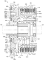
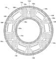
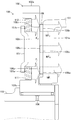
- FIG. 1 It is sectional drawing which shows the outline of the whole structure of the clutch device which concerns on one Embodiment of this invention in the state of clutch ON. It is a front view which shows schematic appearance structure of the outer side plate incorporated in the clutch device shown in FIG. It is a side view which showed the inner peripheral side pressing part, the outer peripheral side pressing part, the radial pressing part, and the auxiliary pressing part in the outer side plate shown in FIG. 2 by shading hatching. It is explanatory drawing which shows the action of the pressing force at the time of transmitting the rotational driving force of the input rotating body in the clutch device shown in FIG. 1 to a clutch outer through an outer side plate.
- FIG. 1 is a cross-sectional view showing an outline of the overall configuration of the clutch device 100 according to the present invention.
- the clutch device 100 is a mechanical device for transmitting and shutting off the driving force of an engine (not shown), which is a prime mover in a two-wheeled vehicle (motorcycle), to wheels (not shown), which are driven objects. It is placed between the transmission and the transmission (not shown).
- the clutch device 100 includes a clutch outer 101.
- the clutch outer 101 is a component for holding the first friction plate 114 and transmitting the driving force from the engine to the first friction plate 114, and is formed by molding an aluminum alloy material into a bottomed cylindrical shape.
- an internal gear-shaped spline is formed in the tubular portion of the clutch outer 101, and a plurality of (10 in this embodiment) first friction plates 114 are clutched on the spline. It is held in a spline-fitted state so that it can be displaced along the axial direction of the outer 101 and can rotate integrally with the clutch outer 101.
- the input rotating body 102 is a metal gear component that is rotationally driven by meshing with a drive gear connected to a driving shaft (not shown) such as a crankshaft that is rotationally driven by driving a prime mover such as an engine, and is a sleeve 103. And, they are rotatably supported by a shaft 118, which will be described later, via a needle bearing 104. That is, the clutch outer 101 is rotationally driven integrally with the input rotating body 102 independently of the shaft 118 at a position concentric with the shaft 118.
- the input rotating body 102 is mainly configured to have a tooth portion 102a, a boss portion 102b, and an overhanging portion 102c.
- the tooth portion 102a is a portion that meshes with the drive gear and receives a rotational driving force, and is formed in a shape that repeats unevenness along the circumferential direction.
- the boss portion 102b is a portion that supports the input rotating body 102 on the shaft 118 and the clutch outer 101, and is formed in a cylindrical shape extending in a direction orthogonal to the circumferential direction of the tooth portion 102a.
- the inner peripheral side of the boss portion 102b is fitted to the sleeve 103 via the needle bearing 104, and the clutch outer 101 is fitted to the outer peripheral side in a slidable state.
- the overhanging portion 102c is a portion that supports the tooth portion 102a on the radial outer side of the boss portion 102b and is connected to the clutch outer 101, and is formed in a flat plate annular shape on the radial outer side of the boss portion 102b.
- a connecting pin penetrating portion 102d and a spring accommodating portion 102e are formed in the overhanging portion 102c, respectively.
- the connecting pin penetrating portion 102d is a portion through which the connecting pin 108, which will be described later, penetrates, and is formed in an elongated hole shape that allows the connecting pin 108 to swing in the circumferential direction.
- the three connecting pin penetrating portions 102d are formed at equal intervals along the circumferential direction of the input rotating body 102, but even if less than three or four or more are provided. It's natural that it's good.
- the spring accommodating portion 102e is a portion accommodating the damper member 113 described later, and is formed in an elongated hole shape extending in the circumferential direction of the input rotating body 102. In this case, both ends of the damper member 113 are elastically abutted against both ends of the spring accommodating portion 102e. In the present embodiment, two spring accommodating portions 102e are formed between each of the three connecting pin penetrating portions 102d along the circumferential direction of the input rotating body 102, but less than two or three. It goes without saying that the above may be provided.
- the sleeve 103 is a component for supporting the input rotating body 102 on the shaft 118 via the needle bearing 104, and is configured by forming a metal material in a cylindrical shape.
- the needle bearing 104 is a component for supporting the input rotating body 102 in a rotatable state on the outer peripheral surface of the sleeve 103, and includes a large number of elongated cylindrical bodies that roll in the circumferential direction on the outer peripheral surface of the sleeve 103. It is formed in a cylindrical shape.
- the damper mechanism 105 is a group of parts for elastically transmitting the rotational driving force of the input rotating body 102 to the clutch outer 101, and mainly includes an outer side plate 106, an input side side plate 107, a connecting pin 108, and an inner ring spring. It is configured to include 111, an outer ring spring 112, and a damper member 113, respectively.
- the outer side plate 106 frictionally slides on the input rotating body 102 and is fixed to the clutch outer 101 by the connecting pin 108 to apply the rotational driving force of the input rotating body 102 to the clutch outer 101. It is a part for transmitting to, and is composed of a metal material formed in a flat plate annular shape.
- the outer side plate 106 is formed to have an inner diameter and an outer diameter facing the inner ring spring 111 and the outer ring spring 112, which will be described later, which are pressed against the input rotating body 102, respectively.
- the outer side plate 106 has an inner diameter and an outer diameter facing the outer peripheral portion on the plate surface of the inner ring spring 111 pressed by the input rotating body 102 and the inner peripheral portion on the plate surface of the outer ring spring 112, respectively. Is formed in.
- the inner peripheral portion of the outer side plate 106 on both side surfaces of the outer side plate 106 has the overhanging portion 102c of the input rotating body 102 on the portion of the inner peripheral ring spring 111 facing the outer peripheral portion of the plate surface.
- the inner peripheral side pressing portion 106a which is pressed against the side surface 101a of the clutch outer 101, is formed in an annular shape.
- the overhanging portion 102c of the input rotating body 102 and the side surface 101a of the clutch outer 101 are formed on the portion of the outer ring spring 112 facing the inner peripheral portion of the plate surface.
- the outer peripheral side pressing portion 106b to be pressed is formed in an annular shape.
- the inner peripheral side pressing portion 106a and the outer peripheral side pressing portion 106b are continuously connected to the plate surfaces on both sides of the outer side plate 106 without being chipped in the radial direction, and the overhanging portion 102c of the input rotating body 102 and the clutch.
- a radial pressing portion 106c to be pressed is formed on the side surface 101a of the outer 101, respectively.
- the radial pressing portion 106c is a region that continuously connects the inner peripheral side pressing portion 106a and the outer peripheral side pressing portion 106b in the radial direction
- the outer side plate 106 is circumferentially peripherally oriented from the inside to the outside in the radial direction. It is formed in a fan shape with a wide range of directions.
- each radial pressing portion 106c includes a radial pressing portion 106c having a different circumferential width as a part of nine radial pressing portions 106c arranged in the circumferential direction. Specifically, in each radial pressing portion 106c, three radial pressing portions 106c having a narrow circumferential width are evenly arranged in the circumferential direction between six radial pressing portions 106c having a wide circumferential width. ing.
- each radial pressing portion 106c is formed to be wider than the width of the narrowest portion in each circumferential direction of the inner peripheral side pressing portion 106a and the outer peripheral side pressing portion 106b. Further, the radial pressing portion 106c is formed at the same position and the same shape for each of the three connecting pin penetrating portions 106e provided along the circumferential direction of the outer side plate 106 as a unit.
- the overhanging portion 102c of the input rotating body 102 and the clutch outer 101 are placed on the portions other than the inner peripheral side pressing portion 106a, the outer peripheral side pressing portion 106b and the radial pressing portion 106c.
- Auxiliary pressing portions 106d that are pressed on the side surfaces 101a are formed.
- auxiliary pressing portion 106d is not shown.
- each of the inner peripheral side pressing portion 106a, the outer peripheral side pressing portion 106b, the radial pressing portion 106c, and the auxiliary pressing portion 106d is not shown.
- the inner peripheral side pressing portion 106a and the outer peripheral side pressing portion 106b are shown by dark hatching
- the radial pressing portion 106c is shown by medium-thickness hatching
- the auxiliary pressing portion 106d is shown by light hatching. ing.
- the inner peripheral side pressing portion 106a, the outer peripheral side pressing portion 106b, the radial pressing portion 106c, and the auxiliary pressing portion 106d are formed on both surfaces of the outer side plate 106 on the same plane. Further, the inner peripheral side pressing portion 106a, the outer peripheral side pressing portion 106b, and the radial pressing portion 106c are formed so that the total area thereof is larger than the total area of each opening of the connecting pin penetrating portion 106e and the spring accommodating portion 106f, which will be described later. Has been done.
- the inner peripheral side pressing portion 106a and the outer peripheral side pressing portion 106b have the total area in which the outer side plate 106 contacts the input rotating body 102 and the clutch outer 101, respectively, that is, the inner peripheral side pressing portion 106a and the outer peripheral side pressing portion 106b. , It is formed so as to have a size of at least 40% or more with respect to the total area of the radial pressing portion 106c and the auxiliary pressing portion 106d. Further, the inner peripheral side pressing portion 106a, the outer peripheral side pressing portion 106b, and the radial pressing portion 106c have the total area in which the outer side plate 106 contacts the input rotating body 102 and the clutch outer 101, that is, the inner peripheral side pressing portion 106a. The outer peripheral side pressing portion 106b, the radial pressing portion 106c, and the auxiliary pressing portion 106d are formed so as to have a size of at least 70% or more with respect to the total area.
- the outer side plate 106 is formed with a connecting pin penetrating portion 106e and a spring accommodating portion 106f, respectively.
- the connecting pin penetrating portion 106e is a portion through which the connecting pin 108 penetrates, and is composed of a circular through hole substantially the same as the outer diameter of the connecting pin 108.
- the three connecting pin penetrating portions 106e are formed at equal intervals along the circumferential direction of the outer side plate 106, but even if less than three or four or more are provided. It's natural that it's good.
- the spring accommodating portion 106f is a portion accommodating the damper member 113 accommodated in the spring accommodating portion 102e, and has an elongated hole shape with a cover extending in the circumferential direction of the outer side plate 106 while covering a part of the damper member 113. It is formed. In this case, both ends of the damper member 113 are elastically abutted against both ends of the spring accommodating portion 106f. In this embodiment, two spring accommodating portions 106f are formed between each of the three connecting pin penetrating portions 106e along the circumferential direction of the outer side plate 106, but less than two or three. It goes without saying that the above may be provided.
- the input side side plate 107 is a component for restricting the displacement of the input rotating body 102 to the side opposite to the outer side plate 106 (left side in the drawing), and is formed by forming a metal material in a flat plate annular shape. ..
- the input side side plate 107 is formed to have an inner diameter and an outer diameter capable of pressing the outer peripheral portion on the plate surface of the inner ring spring 111 and the inner peripheral portion on the plate surface of the outer ring spring 112, respectively. That is, the input side side plate 107 is formed with an inner ring pressing portion 107a for pressing the inner ring spring 111 on the innermost peripheral portion of the plate surface, and an outer ring pressing portion 107a for pressing the outer ring spring 112 on the outermost peripheral portion. Part 107b is formed.
- a connecting pin penetrating portion 107c and a spring accommodating portion 107d are formed on the plate surface of the input side side plate 107, respectively.
- the connecting pin penetrating portion 107c is a portion through which the connecting pin 108 penetrates, and is composed of a circular through hole substantially the same as the outer diameter of the connecting pin 108.
- three connecting pin penetrating portions 107c are formed with equal intervals along the circumferential direction of the input side side plate 107, but less than three or four or more are provided. It is natural that it is also good.
- the spring accommodating portion 107d is a portion accommodating the damper member 113 accommodated in the spring accommodating portion 102e, and has an elongated hole shape with a cover extending in the circumferential direction of the input side side plate 107 while covering a part of the damper member 113. Is formed in. In this case, both ends of the damper member 113 are elastically abutted against both ends of the spring accommodating portion 107d. In this embodiment, two spring accommodating portions 107d are formed between each of the three connecting pin penetrating portions 107c along the circumferential direction of the input side side plate 107, but less than two or three. It goes without saying that more than one may be provided.
- the connecting pin 108 is a component for integrally connecting the input rotating body 102 and the clutch outer 101 via the outer side plate 106, the input side side plate 107, the inner ring spring 111, and the outer ring spring 112, and is made of metal.
- the material is formed in a rod shape.
- the connecting pin 108 is composed of three rivets penetrating the input side side plate 107 and the clutch outer 101. In this case, each of the three connecting pins 108 penetrates the connecting pin penetrating portion 107c of the input rotating body 102 via a collar 108a formed of a metal material in a cylindrical shape.
- the inner ring spring 111 and the outer ring spring 112 are arranged between the input side side plate 107 and the clutch outer 101 to press the outer side plate 106 against the input rotating body 102, and are formed in a flat plate annular shape. It is composed of a plurality of spring steels stacked on top of each other.
- the inner ring spring 111 is arranged in a compressed and deformed state between the overhanging portion 102c of the input rotating body 102 and the inner ring pressing portion 107a of the input side side plate 107.
- the inner ring spring 111 is provided at a position in the radial direction substantially the same as the outer peripheral side end portion on the side surface 101a of the clutch outer 101.
- the outer ring spring 112 is arranged in a compressed and deformed state between the overhanging portion 102c of the input rotating body 102 and the outer ring pressing portion 107b of the input side side plate 107.
- the outer ring spring 112 is provided at a position in the radial direction substantially the same as the inner peripheral side end portion on the side surface 101a of the clutch outer 101.
- the inner ring spring 111 and the outer ring spring 112 may be composed of springs that exert a pressing force of the same strength as each other, or may be composed of springs that exert a pressing force of different strengths from each other. The strength of each spring is adjusted so that the pressing force is substantially constant in the region of the outer side plate 106 from the inner peripheral side pressing portion 106a to the outer peripheral side pressing portion 106b.
- These inner ring springs 111 and outer ring springs 112 correspond to the ring springs according to the present invention.
- the damper member 113 is a component that transmits the fluctuation of the rotational driving force (torque) of the input rotating body 102 to the clutch outer 101 while attenuating it, and is composed of a steel coil spring.
- the damper member 113 is arranged in each of the spring accommodating portions 102e, 106f, 107d formed at the same position in each circumferential direction of the input rotating body 102, the outer side plate 106, and the input side side plate 107.
- the damper member 113 may be made of an elastic body made of a rubber material or the like in addition to the coil spring.
- the first friction plate 114 is a flat plate annular part pressed against the second friction plate 115, and is formed by forming a thin plate material made of an aluminum material into an annular shape. In this case, external teeth that mesh with the internal tooth-shaped spline of the clutch outer 101 are formed on the outer peripheral portion of each first friction plate 114. Friction materials made of a plurality of pieces of paper (not shown) are attached to both side surfaces (front and back surfaces) of the first friction plate 114, and oil grooves (not shown) are formed between the friction materials. There is. Further, these first friction plates 114 are formed to have the same size and shape for each of the center clutch 116 and the pressure clutch 117 provided inside the clutch outer 101.
- the second friction plate 115 is a flat plate annular part pressed against the first friction plate 114, and is formed by punching a thin plate material made of SPCC (cold rolled steel plate) material in an annular shape. Oil grooves (not shown) having a depth of several ⁇ m to several tens of ⁇ m for holding clutch oil are formed on both side surfaces (front and back surfaces) of the second friction plate 115, and wear resistance is improved. Surface hardening treatment is applied for the purpose of making them.
- SPCC cold rolled steel plate
- each second friction plate 115 an internal gear shape that splines fits to the plate holding portion 116d formed in the center clutch 116 and the plate sub holding portion 117c formed in the pressure clutch 117, respectively. Each spline is formed.
- These second friction plates 115 are formed to have the same size and shape for each of the center clutch 116 and the pressure clutch 117. It goes without saying that the friction material may be provided on the second friction plate 115 instead of the first friction plate 114.
- the center clutch 116 is a component for accommodating the second friction plate 115 together with the first friction plate 114 and transmitting the driving force of the engine to the transmission side, and is configured by molding an aluminum alloy material into a substantially cylindrical shape. Has been done. More specifically, the center clutch 116 is mainly configured by integrally forming a shaft connecting portion 116a, a ring-shaped intermediate portion 116b, and a plate holding portion 116d.
- the shaft connecting portion 116a is a portion connected to the shaft 118 while the pressure clutch 117 is fitted, and is formed in a cylindrical shape extending in the axial direction at the center of the center clutch 116.
- An internal gear-shaped spline is formed on the inner peripheral surface of the shaft connecting portion 116a along the axial direction of the center clutch 116, and the shaft 118 is spline-fitted to this spline. That is, the center clutch 116 rotates integrally with the shaft 118 at a position concentric with the clutch outer 101 and the shaft 118.
- the ring-shaped intermediate portion 116b is a flange-shaped portion formed between the shaft connecting portion 116a and the plate holding portion 116d.
- Three through holes are formed in the ring-shaped intermediate portion 116b along the circumferential direction, and three tubular columns 117b, which will be described later, penetrate through these through holes.
- the assist torque which is a force for enhancing the pressure contact force between the first friction plate 114 and the second friction plate 115, or the first friction plate 114 and the second friction plate 115 are separated from each other at an early stage.
- the plate holding portion 116d is a portion that holds a part of the plurality of second friction plates 115 together with the first friction plate 114, and is formed in a cylindrical shape extending in the axial direction on the outer edge portion of the center clutch 116.
- the outer peripheral portion of the plate holding portion 116d is formed of external gear-shaped splines, and the second friction plate 115 and the first friction plate 114 are alternately arranged along the axial direction of the center clutch 116. It is held in a state where it can be displaced and can rotate integrally with the center clutch 116.
- the plate holding portion 116d is formed with a plate receiving portion 116e at the tip on the right side of the drawing.
- the plate receiving portion 116e is a portion that receives the second friction plate 115 and the first friction plate 114 pressed by the pressure clutch 117 and sandwiches them with the pressure clutch 117, and is a cylindrically formed plate holding portion 116d.
- the tip portion is formed so as to project radially outward in a flange shape.
- the pressure clutch 117 is a component for bringing the first friction plate 114 and the second friction plate 115 into close contact with each other by pressing the first friction plate 114, and the aluminum alloy material is used as the outer diameter of the second friction plate 115. It is formed by molding into a substantially disk shape with an outer diameter of substantially the same size as. More specifically, the pressure clutch 117 is mainly configured by integrally forming a ring-shaped intermediate portion 117a and a plate sub-holding portion 117c.
- the ring-shaped intermediate portion 117a is an annular portion constituting the inner peripheral portion of the pressure clutch 117.
- this ring-shaped intermediate portion 117a three tubular columns 117b are formed along the circumferential direction, and the innermost peripheral portion is slidable on the outer peripheral surface of the shaft connecting portion 116a of the center clutch 116. It is fitted.
- the pressure clutch 117 is provided so as to be rotatable independently of the center clutch 116 and the shaft 118 at a position concentric with the clutch outer 101, the center clutch 116 and the shaft 118.
- the three tubular columns 117b are cylindrical portions extending in a columnar direction in the axial direction of the center clutch 116 to support the lifter plate 120, and female threads are formed on the inner peripheral portions thereof. These three tubular columns 117b are uniformly formed along the circumferential direction of the pressure clutch 117.
- the plate sub-holding portion 117c is a portion that holds the other part of the plurality of second friction plates 115 together with the first friction plate 114, and is formed in a cylindrical shape extending in the axial direction of the outer edge portion of the pressure clutch 117. ing.
- the outer peripheral portion of the plate sub-holding portion 117c is formed of an external gear-shaped spline, and the second friction plate 115 and the first friction plate 114 are alternately arranged along the axial direction of the pressure clutch 117. It is held in a state where it can be displaced and can rotate integrally with the pressure clutch 117.
- a plate pushing portion 117d is formed at the tip of the plate sub-holding portion 117c.
- the plate pushing portion 117d presses the second friction plate 115 and the first friction plate 114 held by the plate sub-holding portion 117c toward the plate receiving portion 116e to raise the second friction plate 115 and the first friction plate 114. It is a portion for being brought into close contact with each other by pressure, and the root portion of the plate sub-holding portion 117c formed in a cylindrical shape is formed so as to project radially outward in a flange shape.
- a cam body 117e constituting the A & S (registered trademark) mechanism is formed between each of the three tubular columns 117b.
- the shaft 118 is a shaft body formed in a hollow shape, and one end side (on the right side in the drawing) rotatably supports the input rotating body 102 and the clutch outer 101 via the sleeve 103 and fits the spline.
- the center clutch 116 is fixedly supported via a nut (not shown).
- the other (left side in the drawing) end of the shaft 118 is connected to a transmission (not shown) in a two-wheeled vehicle. That is, the shaft 118 corresponds to the driven shaft in the present invention.
- the shaft 118 is shown by a chain double-dashed line.
- the lifter plate 120 is a component for reciprocating and reciprocating the pressure clutch 117 in the axial direction, and is configured by forming a metal material in a cylindrical shape.
- the lifter plate 120 is fixed to the tip ends of the three tubular columns 117b via bolts in a state where the outer peripheral portion is slidably fitted to the inner peripheral surface of the plate holding portion 116d. In this case, the lifter plate 120 is mounted on the tubular column 117b in a state where the clutch spring 122 is compressed and deformed.
- the lifter plate 120 displaces the pressure clutch 117 toward the input rotating body 102 by being pressed by the release pin 121 constituting the clutch release mechanism via the bearing.
- the clutch release mechanism is a mechanical device that presses the release pin 121 toward the shaft 118 by operating a clutch operation lever (not shown) of a driver of a self-propelled vehicle on which the clutch device 100 is mounted.
- the release pin 121 is shown by a chain double-dashed line.
- the clutch spring 122 is an elastic body for pressing the plate pushing portion 117d of the pressure clutch 117 against the first friction plate 114 by pressing the pressure clutch 117 toward the center clutch 116, and the spring steel is spirally wound. It is composed of a coil spring.
- the clutch spring 122 is arranged between each of the three tubular columns 117b.
- the clutch device 100 is filled with a predetermined amount of clutch oil (not shown).
- the clutch oil is mainly supplied between the first friction plate 114 and the second friction plate 115 to absorb the frictional heat generated between them and prevent the friction material from being worn. That is, the clutch device 100 is a so-called wet multi-plate friction clutch device.
- the clutch release mechanism (not shown) does not press the release pin 121. Therefore, the pressure clutch 117 presses the first friction plate 114 by the elastic force of the clutch spring 122. As a result, the center clutch 116 is rotationally driven in a clutch ON state in which the first friction plate 114 and the second friction plate 115 are pressed against each other and frictionally connected. That is, the rotational driving force of the prime mover is transmitted to the center clutch 116 to rotationally drive the shaft 118.
- the rotational driving force from the prime mover transmitted to the input rotating body 102 is transmitted to the clutch outer 101 via the outer side plate 106.
- the outer side plate 106 has an inner peripheral side pressing section 106a and the outer pressing portion 106b is formed each of the pressing force F I of the inner ring spring 111 and the outer ring spring 112, on a straight line F O acts Therefore, in the radial direction of the rotational driving force transmitted by increasing the contact force between the input rotating body 102 and the outer side plate 106 and the contact force between the outer side plate 106 and the clutch outer 101 on the same straight line, MF I and MF O. It is possible to suppress unevenness in size.
- the outer side plate 106 can suppress the difference in the amount of rotational driving force transmitted between the innermost frictional contact portion and the outermost frictional contact portion of the outer side plate 106.
- the outer side plate 106 has a radial pressing portion 106c that continuously connects the inner peripheral side pressing portion 106a and the outer peripheral side pressing portion 106b in the radial direction, the inner peripheral side pressing portion 106a and the outer peripheral side It is possible to suppress unevenness in the magnitude of the rotational driving force transmitted by equalizing the adhesion force MF M with the pressing portion 106b in the radial direction.
- the outer side plate 106 can suppress the difference in the transmission amount of the rotational driving force in the region between the innermost friction contact portion and the outermost friction contact portion of the outer side plate 106.
- the clutch device 100 can smoothly transmit the rotational driving force from the prime mover transmitted to the input rotating body 102 to the clutch outer 101.
- FIG. 4 shows a part of the cross section of the portion of the clutch device 100 in which the connecting pin 108 does not exist.
- the clutch spring 122 is compressed and deformed, so that the clutch outer 101 is moved with respect to the input rotating body 102. It rotates relative to each other via the outer side plate 106. Even in this case, the clutch device 100 can smoothly transmit the rotational driving force from the prime mover transmitted to the input rotating body 102 to the clutch outer 101.
- the clutch release mechanism presses the release pin 121, so that the pressure clutch 117 presses the clutch spring 122. It is displaced in the direction away from the center clutch 116 against the elastic force of.
- the center clutch 116 is in a clutch-OFF state in which the frictional connection between the first friction plate 114 and the second friction plate 115 is released, so that the rotational drive is attenuated or the rotational drive is stopped. That is, the rotational driving force of the prime mover is cut off with respect to the center clutch 116. Even in this clutch OFF state, the clutch device 100 can smoothly transmit the rotational driving force from the prime mover transmitted to the input rotating body 102 to the clutch outer 101.
- the clutch device 100 pushes the inner ring spring 111 and the outer ring spring 112 that press the outer side plate 106 against the input rotating body 102 in the radial direction of the outer side plate 106.
- the inner peripheral side pressing portion 106a and the outer peripheral side pressing portion 106a are provided on the inner peripheral side and the outer peripheral side, respectively, and are pressed against the input rotating body 102 and the clutch outer 101 at positions facing the ring springs 111 and 112, respectively.
- the outer side plate 106 is provided.
- the clutch device 100 the input rotating body 102 and the outer side plate 106 are brought into close contact with each other by the ring springs 111 and 112 on the inner peripheral side and the outer peripheral side in the radial direction of the outer side plate 106, and the degree of adhesion between the two is increased. This is improved to reduce the non-uniformity of the load from the ring springs 111 and 112 between the inner peripheral side and the outer peripheral side and the non-uniformity of the friction coefficient in the radial direction of the outer side plate 106. As a result, the clutch device 100 can reduce the vibration generated when the rotational driving force from the prime mover is transmitted by smoothly transmitting the rotational driving force of the input rotating body 102 to the clutch outer 101.
- the inner peripheral side pressing portion 106a and the outer peripheral side pressing portion 106b are at least 40% or more larger than the total area in which the outer side plate 106 contacts the input rotating body 102 and the clutch outer 101, respectively. It is formed so as to be a plate.
- the clutch device 100 can equalize the contact surface pressure on the contact surface of the outer side plate 106 with the input rotating body 102 and the clutch outer 101, and the load from the inner ring spring 111 and the outer ring spring 112 can be equalized.
- the non-uniformity of the clutch can be reduced, and the vibration generated when the rotational driving force is transmitted from the prime mover can be reduced.
- the inner peripheral side pressing portion 106a and the outer peripheral side pressing portion 106b are formed so as to have a size of less than 40% with respect to the total area in which the outer side plate 106 contacts the input rotating body 102 and the clutch outer 101, respectively. It is possible to reduce the non-uniformity of the contact surface pressure.
- the inner peripheral side pressing portion 106a, the outer peripheral side pressing portion 106b, and the radial pressing portion 106c are provided with respect to the total area in which the outer side plate 106 contacts the input rotating body 102 and the clutch outer 101, respectively. It is formed so as to have a size of at least 70% or more.
- the clutch device 100 can further equalize the contact surface pressure on the contact surface of the outer side plate 106 with the input rotating body 102 and the clutch outer 101, and from the inner ring spring 111 and the outer ring spring 112. The non-uniformity of the load can be reduced, and the vibration generated when the rotational driving force is transmitted from the prime mover can be reduced.
- the inner peripheral side pressing portion 106a and the outer peripheral side pressing portion 106b are formed so as to have a size of at least 70% of the total area in which the outer side plate 106 contacts the input rotating body 102 and the clutch outer 101, respectively. It is possible to reduce the non-uniformity of the contact surface pressure.
- the outer side plate 106 is configured by providing the radial pressing portion 106c.
- the outer side plate 106 can be configured by omitting the radial pressing portion 106c.
- the outer side plate 106 may be formed by projecting the inner peripheral side pressing portion 106a and the outer peripheral side pressing portion 106b from the plate surface of the outer side plate 106, thereby omitting the radial pressing portion 106c. it can.
- the outer side plate 106 can also be configured by omitting the auxiliary pressing portion 106d in the same manner.
- the radial pressing portion 106c is formed to be wider than the width of the inner peripheral side pressing portion 106a and the outer peripheral side pressing portion 106b in each circumferential direction.
- the outer side plate 106 improves the surface pressure of the non-linear portion on which the pressing force of the inner ring spring 111 and the outer ring spring 112 acts between the inner peripheral side pressing portion 106a and the outer peripheral side pressing portion 106b. It is possible to reduce the non-uniformity of the contact surface pressure.
- the radial pressing portion 106c can be formed with a width narrower than the width of the inner peripheral side pressing portion 106a and the outer peripheral side pressing portion 106b in the respective circumferential directions.
- the radial pressing portion 106c is formed at the same position and the same shape for each of the three connecting pins 108 provided along the circumferential direction of the outer side plate 106 as a unit. Has been done.
- the clutch device 100 changes the friction characteristics between the connecting pins 108 in the circumferential direction and the behavior of the lubricating oil, and the friction characteristics of the outer side plate 106 when sliding or stationary are monotonous or biased.
- the friction characteristics of the outer side plate 106 as a whole can be made uniform while suppressing the action.
- the radial pressing portion 106c may be formed regularly or irregularly along the circumferential direction of the outer side plate 106 regardless of the connecting pin 108.
- a plurality of radial pressing portions 106c are formed intermittently along the radial direction of the outer side plate 106.
- only one radial pressing portion 106c can be formed in a part along the radial direction of the outer side plate 106.
- the widths of the two radial pressing portions 106c adjacent to each other in the circumferential direction of the outer side plate 106 are configured to be different from each other.
- the radial pressing portion 106c can also be formed so that the width in the circumferential direction of the outer side plate 106 is constant at the same radial position, that is, the same size and the same shape.
- the inner peripheral side pressing portion 106a and the outer peripheral side pressing portion 106b are formed in a continuous annular shape along the circumferential direction of the outer side plate 106.
- the inner peripheral side pressing portion 106a and the outer peripheral side pressing portion 106b can also be formed in an intermittent annular shape along the circumferential direction of the outer side plate 106.
- the inner ring spring 111 and the outer ring spring 112 are provided between the input rotating body 102 and the input side side plate 107.
- the inner ring spring 111 and the outer ring spring 112 may be arranged between the input side side plate 107 and the clutch outer 101 so that the outer side plate 106 can be pressed against the input rotating body 102. Therefore, the inner ring spring 111 and the outer ring spring 112 can be arranged, for example, between the outer side plate 106 and the clutch outer 101. That is, the outer side plate 106 may be provided so as to be directly or indirectly pressed against the input rotating body 102 and the clutch outer 101.
- Spring accommodating part 103 ... Sleeve, 104 ... Needle bearing, 105 ... Damper mechanism, 106 ... Outer side plate, 106a ... Inner peripheral side pressing part, 106b ... Outer peripheral side pressing part, 106c ... Radial pressing part, 106d ... Auxiliary pressing part, 106e ... Connecting Pin penetrating part, 106f ... Spring accommodating part, 107 ... Input side side plate, 107a ... Inner ring pressing part, 107b ... Outer ring pressing part, 107c ... Connecting pin penetrating part, 107d ... Spring accommodating part, 108 ... Connecting pin, 108a ... Collar, 111 ... Inner ring spring, 112 ...
Landscapes
- Engineering & Computer Science (AREA)
- General Engineering & Computer Science (AREA)
- Mechanical Engineering (AREA)
- Physics & Mathematics (AREA)
- Acoustics & Sound (AREA)
- Aviation & Aerospace Engineering (AREA)
- Mechanical Operated Clutches (AREA)
Abstract
原動機からの回転駆動力の伝達時に生じる振動を低減することができるクラッチ装置を提供する。 クラッチ装置(100)は、クラッチアウタ(101)と入力回転体(102)との間にダンパ機構(105)を備えている。ダンパ機構(105)は、アウタサイドプレート(106)、入力側サイドプレート(107)、連結ピン(108)、内側リングスプリング(111)、外側リングスプリング(112)およびダンパ部材(113)をそれぞれ備えて構成されている。アウタサイドプレート(106)は、平板環状に形成されており、内側リングスプリング(111)に対向する最内周部に内周側押圧部(106a)が形成されるとともに外側リングスプリング(112)に対向する最外周部に外周側押圧部(106b)が形成されている。アウタサイドプレート(106)は、内周側押圧部(106a)と外周側押圧部(106b)との間に径方向に延びる径方向押圧部(106c)が形成されている。 図1
Description
本発明は、原動機によって回転駆動する原動軸の回転駆動力を被動体を駆動させる従動軸に伝達および遮断するクラッチ装置に関する。
従来から、二輪自動車や四輪自動車などの車両においては、エンジンなどの原動機と車輪などの被動体との間に配置されて原動機の回転駆動力を被動体に伝達または遮断するためにクラッチ装置が用いられている。一般に、クラッチ装置は、原動機の回転駆動力によって回転する複数の第1摩擦板と被動体に連結された複数の第2摩擦板とを互いに対向配置するとともに、これらの第1摩擦板と第2摩擦板とを密着および離隔させることにより回転駆動力の伝達または遮断を任意に行なうことができる。
例えば、下記特許文献1には、原動機の回転駆動力を入力する入力回転体としてのドリブンギアと複数の第1摩擦板を保持するクラッチアウタとの間に原動機の回転駆動力を弾性的にクラッチアウタに伝達するダンパ機構を備えたクラッチ装置が開示されている。ここで、ダンパ機構は、主として、ダンパスプリング、滑り板、保持板、リベットおよびダイヤフラムばねをそれぞれ備えて構成されている。
しかしながら、上記特許文献1に記載したクラッチ装置においては、原動機からの回転駆動力の伝達時に不可避的に振動が生じるためこの振動の低減は常に求められるものである。そこで、本発明者らは、原動機からの回転駆動力の伝達時に生じる振動を低減するために鋭意試験研究を行ったところ、上記ダンパ機構の改良によって振動の低減効果があるとの知見を得た。
本発明は上記問題に対処するためなされたもので、その目的は、原動機からの回転駆動力の伝達時に生じる振動を低減することができるクラッチ装置を提供することにある。
上記目的を達成するため、本発明の特徴は、原動軸の回転駆動力を従動軸に伝達または遮断するクラッチ装置において、原動軸の回転駆動によって同原動軸とともに回転駆動する入力回転体と、従動軸とともに回転駆動する第2摩擦板に対向配置されて入力回転体の回転駆動によって回転駆動する第1摩擦板を保持する有底筒状に形成されたクラッチアウタと、入力回転体とクラッチアウタとの相対回転を許容しつつ入力回転体の回転駆動力をクラッチアウタに伝達するダンパ機構とを備え、ダンパ機構は、平板環状に形成されて入力回転体とクラッチアウタとの間に配置されたアウタサイドプレートと、平板環状に形成されてアウタサイドプレートに対して入力回転体を介して対向配置される入力側サイドプレートと、入力側サイドプレート、入力回転体およびアウタサイドプレートをそれぞれ貫通するピン状に形成されて入力回転体と前記クラッチアウタとを連結させる連結ピンと、平板環状に形成されて入力側サイドプレートとクラッチアウタとの間に配置されてアウタサイドプレートを入力回転体に押し付けるリングスプリングと、入力側サイドプレートおよびアウタサイドプレートのうちの少なくとも一方と入力回転体とを弾性的に連結するダンパ部材とを有し、リングスプリングは、アウタサイドプレートの径方向における内周側と外周側とにそれぞれ設けられており、アウタサイドプレートは、前記内周側のリングスプリングに対向する位置に入力回転体およびクラッチアウタにそれぞれに押し付けられる内周側押圧部と、前記外周側のリングスプリングに対向する位置に入力回転体およびクラッチアウタにそれぞれに押し付けられる外周側押圧部とをそれぞれ有することにある。
このように構成した本発明の特徴によれば、クラッチ装置は、アウタサイドプレートを入力回転体に押し付けるリングスプリングをアウタサイドプレートの径方向における内周側および外周側にそれぞれ設けるとともに、これらの各リングスプリングに対向する位置に入力回転体およびクラッチアウタにそれぞれに押し付けられる内周側押圧部および外周側押圧部を有したアウタサイドプレートを備えている。これにより、クラッチ装置は、入力回転体とアウタサイドプレートとがアウタサイドプレートの径方向における内周側および外周側で各リングスプリングによって両者間の密着度が向上して内周側と外周側との間におけるリングスプリングからの荷重の不均一さおよびアウタサイドプレートにおける径方向における摩擦係数の不均一さが軽減される。この結果、クラッチ装置は、入力回転体の回転駆動力が円滑にクラッチアウタに伝達されることで原動機からの回転駆動力の伝達時に生じる振動を低減することができる。
また、本発明の他の特徴は、前記クラッチ装置において、アウタサイドプレートは、内周側押圧部および外周側押圧部の合算の面積がアウタサイドプレートが入力回転体およびクラッチアウタにそれぞれ接触する総面積に対して少なくとも40%以上であることにある。
このように構成した本発明の他の特徴によれば、クラッチ装置は、アウタサイドプレートの入力回転体およびクラッチアウタへの接触面における接触面圧の均等化を図ることができ、リングスプリングからの荷重の不均一さが軽減されて原動機からの回転駆動力の伝達時に生じる振動を低減することができる。
また、本発明の他の特徴は、前記クラッチ装置において、アウタサイドプレートは、内周側押圧部と外周側押圧部とがアウタサイドプレートの径方向に連続的に繋がった径方向押圧部を有していることにある。
このように構成した本発明の他の特徴によれば、クラッチ装置は、アウタサイドプレートが内周側押圧部と外周側押圧部とがアウタサイドプレートの径方向に連続的に繋がった径方向押圧部を有しているため、リングスプリングからの荷重をアウタサイドプレートの径方向に沿って加えることができリングスプリングからの荷重の不均一さをより効果的に軽減することができる。
また、本発明の他の特徴は、前記クラッチ装置において、アウタサイドプレートは、内周側押圧部、外周側押圧部および径方向押圧部の合算の面積がアウタサイドプレートが入力回転体およびクラッチアウタにそれぞれ接触する総面積に対して少なくとも70%以上であることにある。
このように構成した本発明の他の特徴によれば、クラッチ装置は、アウタサイドプレートの入力回転体およびクラッチアウタへの接触面における接触面圧の均等化をより一層図ることができ、リングスプリングからの荷重の不均一さが軽減されて原動機からの回転駆動力の伝達時に生じる振動を低減することができる。
また、本発明の他の特徴は、前記クラッチ装置において、径方向押圧部は、内周側押圧部および外周側押圧部の各幅よりも幅広に形成されていることにある。
このように構成した本発明の他の特徴によれば、クラッチ装置は、径方向押圧部がアウタサイドプレートの径方向に沿って断続的に複数形成されているため、リングスプリングからの荷重のアウタサイドプレートの径方向における不均一さを軽減することができる。
また、本発明の他の特徴は、前記クラッチ装置において、径方向押圧部は、アウタサイドプレートの周方向において互いに隣接する2つの径方向押圧部における周方向の各幅が互いに異なっていることにある。
このように構成した本発明の他の特徴によれば、クラッチ装置は、径方向押圧部がアウタサイドプレートの周方向において互いに隣接する2つの径方向押圧部における周方向の各幅が互いに異なっているため、周方向における各径方向押圧部ごとの摩擦特性および潤滑油の挙動に変化を与えてアウタサイドプレートの摺動時または静止時における摩擦特性の単調なまたは偏った作用を抑えて摩擦特性をアウタサイドプレート全体として向上させることができる。
また、本発明の他の特徴は、前記クラッチ装置において、連結ピンは、アウタサイドプレートの周方向に沿って複数設けられており、径方向押圧部は、アウタサイドプレートの周方向に沿って複数設けられた連結ピンの各間を単位として各間ごとに同じ位置および同じ形状で形成されていることにある。
このように構成した本発明の他の特徴によれば、クラッチ装置は、径方向押圧部がアウタサイドプレートの周方向に沿って複数設けられた連結ピンの各間を単位として各間ごとに同じ位置および同じ形状で形成されているため、周方向における各連結ピン間内の摩擦特性および潤滑油の挙動に変化を与えてアウタサイドプレートの摺動時または静止時における摩擦特性の単調なまたは偏った作用を抑えつつアウタサイドプレート全体として摩擦特性を均一化することができる。
以下、本発明に係るクラッチ装置の一実施形態について図面を参照しながら説明する。図1は、本発明に係るクラッチ装置100の全体構成の概略を示す断面図である。このクラッチ装置100は、二輪自動車(オートバイ)における原動機であるエンジン(図示せず)の駆動力を被動体である車輪(図示せず)に伝達および遮断するための機械装置であり、同エンジンと変速機(トランスミッション)(図示せず)との間に配置されるものである。
(クラッチ装置100の構成)
クラッチ装置100は、クラッチアウタ101を備えている。クラッチアウタ101は、第1摩擦板114を保持するとともにこの第1摩擦板114にエンジンからの駆動力を伝達するための部品であり、アルミニウム合金材を有底円筒状に成形して構成されている。より具体的には、クラッチアウタ101の筒状部には、内歯歯車状のスプラインが形成されており、このスプラインに複数枚(本実施形態においては10枚)の第1摩擦板114がクラッチアウタ101の軸線方向に沿って変位可能、かつ同クラッチアウタ101と一体回転可能な状態でスプライン嵌合して保持されている。
クラッチ装置100は、クラッチアウタ101を備えている。クラッチアウタ101は、第1摩擦板114を保持するとともにこの第1摩擦板114にエンジンからの駆動力を伝達するための部品であり、アルミニウム合金材を有底円筒状に成形して構成されている。より具体的には、クラッチアウタ101の筒状部には、内歯歯車状のスプラインが形成されており、このスプラインに複数枚(本実施形態においては10枚)の第1摩擦板114がクラッチアウタ101の軸線方向に沿って変位可能、かつ同クラッチアウタ101と一体回転可能な状態でスプライン嵌合して保持されている。
このクラッチアウタ101は、上記有底円筒状における底部に相当する図示左側の側面101aがダンパ機構105を介して入力回転体102に連結されている。入力回転体102は、エンジンなどの原動機の駆動により回転駆動するクランク軸などの原動軸(図示せず)に連結された駆動ギアと噛合って回転駆動する金属製の歯車部品であり、スリーブ103およびニードルベアリング104を介してそれぞれ後述するシャフト118に回転自在に支持されている。すなわち、クラッチアウタ101は、シャフト118と同心位置でシャフト118と独立して入力回転体102と一体的に回転駆動する。この入力回転体102は、主として、歯部102a,ボス部102bおよび張出部102cを有して構成されている。
歯部102aは、前記駆動ギアに噛み合って回転駆動力を受ける部分であり、円周方向に沿って凹凸を繰り返す形状に形成されている。ボス部102bは、入力回転体102をシャフト118上で支持するとともにクラッチアウタ101を支持する部分であり、歯部102aの円周方向に直交する方向に延びる円筒状に形成されている。このボス部102bは、内周側がニードルベアリング104を介してスリーブ103に嵌合しているとともに、外周側にクラッチアウタ101が摺動自在な状態で嵌合している。
張出部102cは、ボス部102bの径方向外側で歯部102aを支持するとともにクラッチアウタ101に連結される部分であり、ボス部102bの径方向外側に平板円環状に形成されている。この張出部102cには、連結ピン貫通部102dおよびスプリング収容部102eがそれぞれ形成されている。
連結ピン貫通部102dは、後述する連結ピン108が貫通する部分であり、連結ピン108の周方向への揺動を許容する長孔状に形成されている。この連結ピン貫通部102dは、本実施形態においては、入力回転体102の周方向に沿って均等な間隔を介して3つ形成されているが、3つ未満または4つ以上設けられていてもよいことは当然である。
スプリング収容部102eは、後述するダンパ部材113を収容する部分であり、入力回転体102の周方向の延びる長孔状に形成されている。この場合、スプリング収容部102eの両端部は、ダンパ部材113の両端部が弾性的に突き当てられている。このスプリング収容部102eは、本実施形態においては、入力回転体102の周方向に沿って3つの連結ピン貫通部102dの各間にそれぞれ2つずつ形成されているが、2つ未満または3つ以上設けられていてもよいことは当然である。
スリーブ103は、シャフト118上で入力回転体102をニードルベアリング104を介して支持するための部品であり、金属材を円筒状に形成して構成されている。ニードルベアリング104は、スリーブ103の外周面上で入力回転体102を回転自在な状態で支持するための部品であり、スリーブ103の外周面上を周方向に転動する多数の細長い円柱体を備えて円筒状に形成されている。
ダンパ機構105は、入力回転体102の回転駆動力を弾性的にクラッチアウタ101に伝達するための部品群であり、主として、アウタサイドプレート106、入力側サイドプレート107、連結ピン108、内側リングスプリング111、外側リングスプリング112およびダンパ部材113をそれぞれ備えて構成されている。
アウタサイドプレート106は、図1に示すように、入力回転体102に摩擦摺動するとともにクラッチアウタ101に対して連結ピン108によって固定されることで入力回転体102の回転駆動力をクラッチアウタ101に伝達するための部品であり、金属材を平板円環状に形成して構成されている。この場合、アウタサイドプレート106は、入力回転体102に押圧される後述する内側リングスプリング111および外側リングスプリング112にそれぞれ対向する内径および外径に形成される。本実施形態においては、アウタサイドプレート106は、入力回転体102に押圧される内側リングスプリング111の板面における外周部分および外側リングスプリング112の板面における内周部分にそれぞれ対向する内径および外径に形成されている。
これにより、アウタサイドプレート106の両面の板面における内周部分には、図3に示すように、内側リングスプリング111の板面における外周部分に対向する部分に入力回転体102の張出部102cおよびクラッチアウタ101の側面101aにそれぞれ押圧される内周側押圧部106aが円環状に形成されている。また、アウタサイドプレート106の両面の板面における外周部分には、外側リングスプリング112の板面における内周部分に対向する部分に入力回転体102の張出部102cおよびクラッチアウタ101の側面101aにそれぞれ押圧される外周側押圧部106bが円環状に形成されている。
また、アウタサイドプレート106の両面の板面には、内周側押圧部106aと外周側押圧部106bとを径方向に欠けることなく連続的に繋げて入力回転体102の張出部102cおよびクラッチアウタ101の側面101aにそれぞれ押圧される径方向押圧部106cが形成されている。この場合、径方向押圧部106cは、内周側押圧部106aと外周側押圧部106bとを径方向に連続的に繋げる領域であるため、アウタサイドプレート106の径方向内側から外側に向かって周方向の幅が広がる扇状に形成される。
また、径方向押圧部106cは、後述する連結ピン貫通部106eおよびスプリング収容部106fによって断続的に複数(本実施形態においては9つ)形成されている。この場合、各径方向押圧部106cは、周方向に並んだ9つの径方向押圧部106cのうちの一部に周方向の幅が異なる径方向押圧部106cが含まれている。具体的には、各径方向押圧部106cは、周方向の幅が広い6つの径方向押圧部106cの間に周方向の幅が狭い3つの径方向押圧部106cが周方向に均等に配置されている。
また、各径方向押圧部106cは、内周側押圧部106aおよび外周側押圧部106bの各周方向の最も狭い部分の幅よりも幅広に形成されている。また、径方向押圧部106cは、アウタサイドプレート106の周方向に沿って設けられた3つの連結ピン貫通部106eの各間を単位として各間ごとに同じ位置および同じ形状で形成されている。
また、アウタサイドプレート106の両面の板面における内周側押圧部106a、外周側押圧部106bおよび径方向押圧部106c以外の部分には、入力回転体102の張出部102cおよびクラッチアウタ101の側面101aにそれぞれ押圧される補助押圧部106dが形成されている。
なお、図1においては、補助押圧部106dの図示を省略している。また、図2においては、内周側押圧部106a、外周側押圧部106b、径方向押圧部106cおよび補助押圧部106dの各図示を省略している。また、図3においては、内周側押圧部106aおよび外周側押圧部106bを濃いハッチングで示し、径方向押圧部106cを中程度の濃さのハッチングで示し、補助押圧部106dを薄いハッチングで示している。
これらの内周側押圧部106a、外周側押圧部106b、径方向押圧部106cおよび補助押圧部106dは、アウタサイドプレート106の両面にそれぞれ同一平面上に形成されている。また、内周側押圧部106a、外周側押圧部106bおよび径方向押圧部106cは、これらの総面積が後述する連結ピン貫通部106eおよびスプリング収容部106fの各開口部の総面積よりも大きく形成されている。
また、内周側押圧部106aおよび外周側押圧部106bは、アウタサイドプレート106が入力回転体102およびクラッチアウタ101にそれぞれ接触する総面積、すなわち、内周側押圧部106a、外周側押圧部106b、径方向押圧部106cおよび補助押圧部106dの総面積に対して少なくとも40%以上の大きさになるように形成されている。また、内周側押圧部106a、外周側押圧部106bおよび径方向押圧部106cは、アウタサイドプレート106が入力回転体102およびクラッチアウタ101にそれぞれ接触する総面積、すなわち、内周側押圧部106a、外周側押圧部106b、径方向押圧部106cおよび補助押圧部106dの総面積に対して少なくとも70%以上の大きさになるように形成されている。
このアウタサイドプレート106には、連結ピン貫通部106eおよびスプリング収容部106fがそれぞれ形成されている。連結ピン貫通部106eは、連結ピン108が貫通する部分であり、連結ピン108の外径と略同一の円形の貫通孔で構成されている。この連結ピン貫通部106eは、本実施形態においては、アウタサイドプレート106の周方向に沿って均等な間隔を介して3つ形成されているが、3つ未満または4つ以上設けられていてもよいことは当然である。
スプリング収容部106fは、スプリング収容部102eに収容されているダンパ部材113を収容する部分であり、ダンパ部材113の一部を覆いつつアウタサイドプレート106の周方向の延びるカバー付きの長孔状に形成されている。この場合、スプリング収容部106fの両端部は、ダンパ部材113の両端部が弾性的に突き当てられている。このスプリング収容部106fは、本実施形態においては、アウタサイドプレート106の周方向に沿って3つの連結ピン貫通部106eの各間にそれぞれ2つずつ形成されているが、2つ未満または3つ以上設けられていてもよいことは当然である。
入力側サイドプレート107は、入力回転体102のアウタサイドプレート106とは反対側(図示左側)への変位を規制するための部品であり、金属材を平板円環状に形成して構成されている。この場合、入力側サイドプレート107は、内側リングスプリング111の板面における外周部分および外側リングスプリング112の板面における内周部分をそれぞれ押さえることができる内径および外径に形成されている。すなわち、入力側サイドプレート107には、板面の最内周部に内側リングスプリング111を押圧する内側リング押圧部107aが形成されるとともに、最外周部に外側リングスプリング112を押圧する外側リング押圧部107bが形成されている。
また、入力側サイドプレート107の板面には、連結ピン貫通部107cおよびスプリング収容部107dがそれぞれ形成されている。連結ピン貫通部107cは、連結ピン108が貫通する部分であり、連結ピン108の外径と略同一の円形の貫通孔で構成されている。この連結ピン貫通部107cは、本実施形態においては、入力側サイドプレート107の周方向に沿って均等な間隔を介して3つ形成されているが、3つ未満または4つ以上設けられていてもよいことは当然である。
スプリング収容部107dは、スプリング収容部102eに収容されているダンパ部材113を収容する部分であり、ダンパ部材113の一部を覆いつつ入力側サイドプレート107の周方向の延びるカバー付きの長孔状に形成されている。この場合、スプリング収容部107dの両端部は、ダンパ部材113の両端部が弾性的に突き当てられている。このスプリング収容部107dは、本実施形態においては、入力側サイドプレート107の周方向に沿って3つの連結ピン貫通部107cの各間にそれぞれ2つずつ形成されているが、2つ未満または3つ以上設けられていてもよいことは当然である。
連結ピン108は、入力回転体102とクラッチアウタ101とをアウタサイドプレート106、入力側サイドプレート107、内側リングスプリング111および外側リングスプリング112を介して一体的に連結するための部品であり、金属材を棒状に形成して構成されている。本実施形態においては、連結ピン108は、入力側サイドプレート107とクラッチアウタ101とを貫通する3つのリベットで構成されている。この場合、3つの各連結ピン108は、入力回転体102の連結ピン貫通部107cに対して金属材を円筒状に形成したカラー108aを介して貫通している。
内側リングスプリング111および外側リングスプリング112は、入力側サイドプレート107とクラッチアウタ101との間に配置されてアウタサイドプレート106を入力回転体102に押し付けるための部品であり、平板環状に形成して複数のばね鋼を複数枚重ねてそれぞれ構成されている。内側リングスプリング111は、入力回転体102の張出部102cと入力側サイドプレート107の内側リング押圧部107aとの間に圧縮変形した状態で配置されている。
この場合、内側リングスプリング111は、クラッチアウタ101の側面101aにおける外周側端部と略同じ径方向位置に設けられている。また、外側リングスプリング112は、入力回転体102の張出部102cと入力側サイドプレート107の外側リング押圧部107bとの間に圧縮変形した状態で配置されている。この場合、外側リングスプリング112は、クラッチアウタ101の側面101aにおける内周側端部と略同じ径方向位置に設けられている。
また、内側リングスプリング111および外側リングスプリング112は、互いに同じ強さの押圧力を発揮するバネで構成してもよいし互いに異なる強さの押圧力を発揮するバネで構成してもよいが、アウタサイドプレート106における内周側押圧部106aから外周側押圧部106bまでの領域で押圧力が略一定となるように各スプリングの強さが調整される。これらの内側リングスプリング111および外側リングスプリング112が、本発明に係るリングスプリングに相当する。
ダンパ部材113は、入力回転体102の回転駆動力(トルク)の変動を減衰しながらクラッチアウタ101に伝達する部品であり、鋼製のコイルスプリングによって構成されている。このダンパ部材113は、入力回転体102、アウタサイドプレート106および入力側サイドプレート107の各周方向の同じ位置にそれぞれ6つずつ形成されたスプリング収容部102e,106f,107d内にそれぞれ配置されている。なお、ダンパ部材113は、コイルスプリングの他にゴム材などからなる弾性体で構成してもよいことは当然である。
第1摩擦板114は、第2摩擦板115に押し当てられる平板環状の部品であり、アルミニウム材からなる薄板材を環状に成形して構成されている。この場合、各第1摩擦板114の外周部には、クラッチアウタ101の前記内歯状のスプラインに噛み合う外歯が形成されている。これらの第1摩擦板114における各両側面(表裏面)には、図示しない複数の紙片からなる摩擦材が貼り付けられているとともに各摩擦材間に図示しない油溝が形成されて構成されている。また、これらの第1摩擦板114は、クラッチアウタ101の内側に設けられるセンタークラッチ116およびプレッシャークラッチ117ごとにそれぞれ同じ大きさおよび形状に形成されている。
クラッチアウタ101の内側には、複数枚(本実施形態においては9枚)の第2摩擦板115が前記第1摩擦板114で挟まれた状態でセンタークラッチ116およびプレッシャークラッチ117にそれぞれ保持されている。第2摩擦板115は、前記第1摩擦板114に押し当てられる平板環状の部品であり、SPCC(冷間圧延鋼板)材からなる薄板材を環状に打ち抜いて成形されている。これらの第2摩擦板115における各両側面(表裏面)には、クラッチオイルを保持するための深さ数μm~数十μmの図示しない油溝が形成されているとともに、耐摩耗性を向上させる目的で表面硬化処理がそれぞれ施されている。
また、各第2摩擦板115の内周部には、センタークラッチ116に形成されたプレート保持部116dおよびプレッシャークラッチ117に形成されたプレートサブ保持部117cにそれぞれスプライン嵌合する内歯歯車状のスプラインがそれぞれ形成されている。これらの第2摩擦板115は、センタークラッチ116およびプレッシャークラッチ117ごとにそれぞれ同じ大きさおよび形状に形成されている。なお、前記摩擦材は、前記第1摩擦板114に代えてこの第2摩擦板115に設けられていてもよいことは当然である。
センタークラッチ116は、第2摩擦板115を第1摩擦板114とともにそれぞれ収容してエンジンの駆動力を変速機側に伝達するための部品であり、アルミニウム合金材を略円筒状に成形して構成されている。より具体的には、センタークラッチ116は、主として、シャフト連結部116a、リング状中間部116bおよびプレート保持部116dを一体的に形成して構成されている。
シャフト連結部116aは、プレッシャークラッチ117が嵌合しつつシャフト118に連結される部分であり、センタークラッチ116の中心部に軸方向に延びる円筒状に形成されている。このシャフト連結部116aの内周面には、センタークラッチ116の軸線方向に沿って内歯歯車状のスプラインが形成されており、このスプラインにシャフト118がスプライン嵌合している。すなわち、センタークラッチ116は、クラッチアウタ101およびシャフト118と同心位置でシャフト118とともに一体的に回転する。
リング状中間部116bは、シャフト連結部116aとプレート保持部116dとの間に形成されたフランジ状の部分である。このリング状中間部116bには、周方向に沿って3つの貫通孔が形成されており、これらの貫通孔に後述する3つの筒状支柱117bがそれぞれ貫通している。
なお、リング状中間部116bには、第1摩擦板114と第2摩擦板115との圧接力を増強する力であるアシストトルクまたは第1摩擦板114と第2摩擦板115とを早期に離隔させて半クラッチ状態に移行させる力であるスリッパートルクを生じさせるA&S(登録商標)機構を構成する傾斜面からなるカム面を有した台状のカム体116cが形成されているが、このカム体114cを含むA&S(登録商標)機構は本発明に直接関わらないため、その説明は省略する。また、リング状中間部114bは、このA&S(登録商標)機構を省略して構成することもできる。
プレート保持部116dは、前記複数枚の第2摩擦板115の一部を第1摩擦板114とともに保持する部分であり、センタークラッチ116の外縁部に軸方向に延びる円筒状に形成されている。このプレート保持部116dは、外周部が外歯歯車状のスプラインで構成されており、第2摩擦板115と第1摩擦板114とを交互に配置した状態でセンタークラッチ116の軸線方向に沿って変位可能かつ同センタークラッチ116と一体回転可能な状態で保持している。
このプレート保持部116dには、図示右側の先端部にプレート受け部116eが形成されている。プレート受け部116eは、プレッシャークラッチ117に押圧された第2摩擦板115および第1摩擦板114を受け止めてこれらをプレッシャークラッチ117とで挟む部分であり、円筒状に形成されたプレート保持部116dの先端部が径方向外側にフランジ状に張り出して形成されている。
プレッシャークラッチ117は、第1摩擦板114を押圧することによってこの第1摩擦板114と第2摩擦板115とを互いに密着させるための部品であり、アルミニウム合金材を第2摩擦板115の外径と略同じ大きさの外径の略円盤状に成形して構成されている。より具体的には、プレッシャークラッチ117は、主として、リング状中間部117aおよびプレートサブ保持部117cを一体的に形成して構成されている。
リング状中間部117aは、プレッシャークラッチ117の内周部分を構成する円環状の部分である。このリング状中間部117aは、周方向に沿って3つの筒状支柱117bがそれぞれ形成されており、最内周部がセンタークラッチ116におけるシャフト連結部116aの外周面上に摺動自在な状態で嵌合している。これにより、プレッシャークラッチ117は、クラッチアウタ101、センタークラッチ116およびシャフト118と同心位置でセンタークラッチ116およびシャフト118とは独立して回転可能に設けられている。
3つの筒状支柱117bは、リフタープレート120を支持するためにセンタークラッチ116の軸方向に柱状に延びた円筒状の部分であり、その内周部に雌ネジが形成されている。これら3つの筒状支柱117bは、プレッシャークラッチ117の周方向に沿って均等に形成されている。
プレートサブ保持部117cは、前記複数枚の第2摩擦板115の他の一部を第1摩擦板114とともに保持する部分であり、プレッシャークラッチ117の外縁部の軸方向に延びる円筒状に形成されている。このプレートサブ保持部117cは、外周部が外歯歯車状のスプラインで構成されており、第2摩擦板115と第1摩擦板114とを交互に配置した状態でプレッシャークラッチ117の軸線方向に沿って変位可能かつ同プレッシャークラッチ117と一体回転可能な状態で保持している。このプレートサブ保持部117cには、先端部にプレート押し部117dが形成されている。
プレート押し部117dは、プレートサブ保持部117cに保持された第2摩擦板115および第1摩擦板114をプレート受け部116e側に押圧して第2摩擦板115と第1摩擦板114とを高い圧力で互いに密着させるための部分であり、円筒状に形成されたプレートサブ保持部117cの根元部分が径方向外側にフランジ状に張り出して形成されている。なお、このリング状中間部117aには、3つの筒状支柱117bの各間に前記A&S(登録商標)機構を構成するカム体117eが形成されている。
シャフト118は、中空状に形成された軸体であり、一方(図示右側)の端部側がスリーブ103を介して入力回転体102およびクラッチアウタ101を回転自在に支持するとともに、前記スプライン嵌合するセンタークラッチ116をナット(図示せず)を介して固定的に支持する。このシャフト118における他方(図示左側)の端部は、二輪自動車における変速機(図示せず)に連結されている。すなわち、シャフト118は、本発明における従動軸に相当する。なお、図1において、シャフト118を二点鎖線で示している。
リフタープレート120は、プレッシャークラッチ117を軸方向に往復変位させるための部品であり、金属材を円筒状に形成して構成されている。このリフタープレート120は、外周部がプレート保持部116dの内周面に摺動自在に嵌合した状態で前記3つの筒状支柱117bの先端部にボルトを介して固定されている。この場合、リフタープレート120は、クラッチスプリング122を圧縮変形させた状態で筒状支柱117b上に取り付けられている。
そして、このリフタープレート120は、クラッチレリーズ機構を構成するレリーズピン121にベアリングを介して押圧されることでプレッシャークラッチ117を入力回転体102側に変位させる。ここで、クラッチレリーズ機構とは、クラッチ装置100が搭載される自走式車両の運転者のクラッチ操作レバー(図示しない)の操作によってレリーズピン121をシャフト118側に押圧する機械装置である。なお、図1において、レリーズピン121を二点鎖線で示している。
クラッチスプリング122は、プレッシャークラッチ117をセンタークラッチ116側に押圧することによってプレッシャークラッチ117のプレート押し部117dを第1摩擦板114に押圧するための弾性体であり、ばね鋼を螺旋状に巻いたコイルスプリングによって構成されている。このクラッチスプリング122は、3つの筒状支柱117bの各間にそれぞれ配置されている。
そして、このクラッチ装置100内には、所定量のクラッチオイル(図示しない)が充填されている。クラッチオイルは、主として、第1摩擦板114と第2摩擦板115との間に供給されてこれらの間で生じる摩擦熱の吸収や摩擦材の摩耗を防止する。すなわち、このクラッチ装置100は、所謂湿式多板摩擦クラッチ装置である。
(クラッチ装置100の作動)
次に、上記のように構成したクラッチ装置100の作動について説明する。このクラッチ装置100は、前記したように、車両におけるエンジンと変速機との間に配置されるものであり、車両の運転者によるクラッチ操作レバーの操作によってエンジンの駆動力の変速機への伝達および遮断を行なう。
次に、上記のように構成したクラッチ装置100の作動について説明する。このクラッチ装置100は、前記したように、車両におけるエンジンと変速機との間に配置されるものであり、車両の運転者によるクラッチ操作レバーの操作によってエンジンの駆動力の変速機への伝達および遮断を行なう。
具体的には、クラッチ装置100は、車両の運転者(図示せず)がクラッチ操作レバー(図示せず)を操作しない場合においては、クラッチレリーズ機構(図示せず)がレリーズピン121を押圧しないため、プレッシャークラッチ117がクラッチスプリング122の弾性力によって第1摩擦板114を押圧する。これにより、センタークラッチ116は、第1摩擦板114と第2摩擦板115とが互いに押し当てられて摩擦連結されたクラッチONの状態となって回転駆動する。すなわち、原動機の回転駆動力がセンタークラッチ116に伝達されてシャフト118が回転駆動する。
このようなクラッチON状態においては、入力回転体102に伝達された原動機からの回転駆動力は、アウタサイドプレート106を介してクラッチアウタ101に伝達される。この場合、アウタサイドプレート106は、内側リングスプリング111および外側リングスプリング112の各押圧力FI,FOが作用する直線上に内周側押圧部106aおよび外周側押圧部106bが形成されているため、同直線上における入力回転体102とアウタサイドプレート106との密着力およびアウタサイドプレート106とクラッチアウタ101との密着力MFI,MFOを高めて伝達される回転駆動力の径方向における大きさのムラを抑えることができる。特に、アウタサイドプレート106は、アウタサイドプレート106における最も内側の摩擦接触部分と最も外側の摩擦接触部分とにおける回転駆動力の伝達量の差を抑えることができる。
また、アウタサイドプレート106は、内周側押圧部106aと外周側押圧部106bとを径方向に連続的に繋ぐ径方向押圧部106cを有しているため、内周側押圧部106aと外周側押圧部106bとの間の密着力MFMを均一化して伝達される回転駆動力の径方向における大きさのムラを抑えることができる。特に、アウタサイドプレート106は、アウタサイドプレート106における最も内側の摩擦接触部分と最も外側の摩擦接触部分との間の領域における回転駆動力の伝達量の差を抑えることができる。これにより、クラッチ装置100は、入力回転体102に伝達された原動機からの回転駆動力を円滑にクラッチアウタ101に伝達することができる。なお、図4においては、密着力MFI,MFO,MFMの大きさを誇張して示している。また、図4は、クラッチ装置100における連結ピン108が存在しない部分の断面の一部を示している。
また、このクラッチON状態においては、原動機側の回転数よりも駆動輪側の回転数が下回った場合には、クラッチスプリング122が圧縮変形することにより、入力回転体102に対してクラッチアウタ101がアウタサイドプレート106を介して相対回転する。この場合においても、クラッチ装置100は、入力回転体102に伝達された原動機からの回転駆動力を円滑にクラッチアウタ101に伝達することができる。
一方、クラッチ装置100は、クラッチON状態において車両の運転者がクラッチ操作レバーを操作した場合には、クラッチレリーズ機構(図示せず)がレリーズピン121を押圧するため、プレッシャークラッチ117がクラッチスプリング122の弾性力に抗してセンタークラッチ116から離隔する方向に変位する。これにより、センタークラッチ116は、第1摩擦板114と第2摩擦板115との摩擦連結が解消されたクラッチOFFの状態となるため、回転駆動が減衰または回転駆動が停止する状態となる。すなわち、原動機の回転駆動力がセンタークラッチ116に対して遮断される。このクラッチOFF状態においても、クラッチ装置100は、入力回転体102に伝達された原動機からの回転駆動力を円滑にクラッチアウタ101に伝達することができる。
そして、このクラッチOFF状態において運転者クラッチ操作レバーを解除した場合には、クラッチレリーズ機構(図示せず)によるレリーズピン121を介したリフタープレート120の押圧が解除されるため、プレッシャークラッチ117がクラッチスプリング122の弾性力によってセンタークラッチ116に接近する方向に変位する。また、このクラッチOFF状態からクラッチON状態に移行する過程においても、クラッチ装置100は、入力回転体102に伝達された原動機からの回転駆動力を円滑にクラッチアウタ101に伝達することができる。
上記作動説明からも理解できるように、上記実施形態によれば、クラッチ装置100は、アウタサイドプレート106を入力回転体102に押し付ける内側リングスプリング111および外側リングスプリング112をアウタサイドプレート106の径方向における内周側および外周側にそれぞれ設けるとともに、これらの各リングスプリング111,112に対向する位置に入力回転体102およびクラッチアウタ101にそれぞれに押し付けられる内周側押圧部106aおよび外周側押圧部106bを有したアウタサイドプレート106を備えている。これにより、クラッチ装置100は、入力回転体102とアウタサイドプレート106とがアウタサイドプレート106の径方向における内周側および外周側で各リングスプリング111,112によって密着して両者間の密着度が向上して内周側と外周側との間における各リングスプリング111,112からの荷重の不均一さおよびアウタサイドプレート106における径方向における摩擦係数の不均一さが軽減される。この結果、クラッチ装置100は、入力回転体102の回転駆動力が円滑にクラッチアウタ101に伝達されることで原動機からの回転駆動力の伝達時に生じる振動を低減することができる。
さらに、本発明の実施にあたっては、上記実施形態に限定されるものではなく、本発明の目的を逸脱しない限りにおいて種々の変更が可能である。
例えば、上記実施形態においては、内周側押圧部106aおよび外周側押圧部106bは、アウタサイドプレート106が入力回転体102およびクラッチアウタ101にそれぞれ接触する総面積に対して少なくとも40%以上の大きさになるように形成されている。これにより、クラッチ装置100は、アウタサイドプレート106の入力回転体102およびクラッチアウタ101への接触面における接触面圧の均等化を図ることができ、内側リングスプリング111および外側リングスプリング112からの荷重の不均一さが軽減されて原動機からの回転駆動力の伝達時に生じる振動を低減することができる。しかし、内周側押圧部106aおよび外周側押圧部106bは、アウタサイドプレート106が入力回転体102およびクラッチアウタ101にそれぞれ接触する総面積に対して40%未満の大きさになるように形成することができ、前記接触面圧の不均一さを低減することはできる。
また、上記実施形態においては、内周側押圧部106a、外周側押圧部106bおよび径方向押圧部106cは、アウタサイドプレート106が入力回転体102およびクラッチアウタ101にそれぞれ接触する総面積に対して少なくとも70%以上の大きさになるように形成されている。これにより、クラッチ装置100は、アウタサイドプレート106の入力回転体102およびクラッチアウタ101への接触面における接触面圧の均等化をより一層図ることができ、内側リングスプリング111および外側リングスプリング112からの荷重の不均一さが軽減されて原動機からの回転駆動力の伝達時に生じる振動を低減することができる。しかし、内周側押圧部106aおよび外周側押圧部106bは、アウタサイドプレート106が入力回転体102およびクラッチアウタ101にそれぞれ接触する総面積に対して少なくとも70%未満の大きさになるように形成することができ、前記接触面圧の不均一さを低減することはできる。
また、上記実施形態においては、アウタサイドプレート106は、径方向押圧部106cを設けて構成した。しかし、アウタサイドプレート106は、径方向押圧部106cを省略して構成することもできる。この場合、アウタサイドプレート106は、内周側押圧部106aおよび外周側押圧部106bをアウタサイドプレート106の板面から突出させて形成することで径方向押圧部106cを省略して構成することができる。なお、アウタサイドプレート106は、補助押圧部106dについても同様に省略して構成することができる。
また、上記実施形態においては、径方向押圧部106cは、内周側押圧部106aおよび外周側押圧部106bの各周方向の幅よりも幅広に形成されている。これにより、アウタサイドプレート106は、内周側押圧部106aおよび外周側押圧部106bとの間における内側リングスプリング111および外側リングスプリング112の押圧力が作用する線状にない部分の面圧力を向上させて接触面圧の不均一さを低減することはできる。しかし、径方向押圧部106cは、内周側押圧部106aおよび外周側押圧部106bの各周方向の幅よりも狭い幅で形成することもできる。
また、上記実施形態においては、径方向押圧部106cは、アウタサイドプレート106の周方向に沿って設けられた3つの連結ピン108の各間を単位として各間ごとに同じ位置および同じ形状で形成されている。これにより、クラッチ装置100は、周方向における各連結ピン108間内の摩擦特性および潤滑油の挙動に変化を与えてアウタサイドプレート106の摺動時または静止時における摩擦特性の単調なまたは偏った作用を抑えつつアウタサイドプレート106全体として摩擦特性を均一化することができる。しかし、径方向押圧部106cは、アウタサイドプレート106の周方向に沿って連結ピン108とは無関係に規則的または不規則に形成してもよい。
また、上記実施形態においては、径方向押圧部106cは、アウタサイドプレート106の径方向に沿って断続的に複数形成した。しかし、径方向押圧部106cは、アウタサイドプレート106の径方向に沿って一部分に1つだけ形成することもできる。
また、上記実施形態においては、一部の径方向押圧部106cについて、アウタサイドプレート106の周方向において互いに隣接する2つの径方向押圧部106cにおける周方向の各幅が互いに異なるように構成した。しかし、径方向押圧部106cは、アウタサイドプレート106の周方向において周方向の幅を同一の径方向位置で一定、すなわち、同じ大きさ同じ形状で形成することもできる。
また、上記実施形態においては、内周側押圧部106aおよび外周側押圧部106bは、アウタサイドプレート106の周方向に沿って連続的な環状に形成した。しかし、内周側押圧部106aおよび外周側押圧部106bは、アウタサイドプレート106の周方向に沿って断続的な環状に形成することもできる。
また、上記実施形態においては、内側リングスプリング111および外側リングスプリング112は、入力回転体102と入力側サイドプレート107との間に設けた。しかし、内側リングスプリング111および外側リングスプリング112は、入力側サイドプレート107とクラッチアウタ101との間に配置されてアウタサイドプレート106を入力回転体102に押し付けることができればよい。したがって、内側リングスプリング111および外側リングスプリング112は、例えば、アウタサイドプレート106とクラッチアウタ101との間に配置することもできる。すなわち、アウタサイドプレート106は、入力回転体102およびクラッチアウタ101に対して直接的または間接的に押付けられるように設けられていればよい。
FI…内側リングスプリングの押圧力、FO…外側リングスプリングの押圧力、MFI…アウタサイドプレートの内周側部分に対する入力回転体およびクラッチアウタの各密着力、MFO…アウタサイドプレートの外周側部分に対する入力回転体およびクラッチアウタの各密着力、MFM…アウタサイドプレートの中間部分に対する入力回転体およびクラッチアウタの各密着力、
100…クラッチ装置、101…クラッチアウタ、101a…側面、102…入力回転体、102a…歯部、102b…ボス部、102c…張出部、102d…連結ピン貫通部、102e…スプリング収容部、103…スリーブ、104…ニードルベアリング、105…ダンパ機構、106…アウタサイドプレート、106a…内周側押圧部、106b…外周側押圧部、106c…径方向押圧部、106d…補助押圧部、106e…連結ピン貫通部、106f…スプリング収容部、107…入力側サイドプレート、107a…内側リング押圧部、107b…外側リング押圧部、107c…連結ピン貫通部、107d…スプリング収容部、108…連結ピン、108a…カラー、111…内側リングスプリング、112…外側リングスプリング、113…ダンパ部材、114…第1摩擦板、115…第2摩擦板、116…センタークラッチ、116a…シャフト連結部、116b…リング状中間部、116c…カム体、116d…プレート保持部、116e…プレート受け部、117…プレッシャークラッチ、117a…リング状中間部、117b…筒状支柱、117c…プレートサブ保持部、117d…プレート押し部、117e…カム体、118…シャフト、120…リフタープレート、121…レリーズピン、122…クラッチスプリング。
100…クラッチ装置、101…クラッチアウタ、101a…側面、102…入力回転体、102a…歯部、102b…ボス部、102c…張出部、102d…連結ピン貫通部、102e…スプリング収容部、103…スリーブ、104…ニードルベアリング、105…ダンパ機構、106…アウタサイドプレート、106a…内周側押圧部、106b…外周側押圧部、106c…径方向押圧部、106d…補助押圧部、106e…連結ピン貫通部、106f…スプリング収容部、107…入力側サイドプレート、107a…内側リング押圧部、107b…外側リング押圧部、107c…連結ピン貫通部、107d…スプリング収容部、108…連結ピン、108a…カラー、111…内側リングスプリング、112…外側リングスプリング、113…ダンパ部材、114…第1摩擦板、115…第2摩擦板、116…センタークラッチ、116a…シャフト連結部、116b…リング状中間部、116c…カム体、116d…プレート保持部、116e…プレート受け部、117…プレッシャークラッチ、117a…リング状中間部、117b…筒状支柱、117c…プレートサブ保持部、117d…プレート押し部、117e…カム体、118…シャフト、120…リフタープレート、121…レリーズピン、122…クラッチスプリング。
Claims (8)
- 原動軸の回転駆動力を従動軸に伝達または遮断するクラッチ装置において、
前記原動軸の回転駆動によって同原動軸とともに回転駆動する入力回転体と、
前記従動軸とともに回転駆動する第2摩擦板に対向配置されて前記入力回転体の回転駆動によって回転駆動する第1摩擦板を保持する有底筒状に形成されたクラッチアウタと、
前記入力回転体と前記クラッチアウタとの相対回転を許容しつつ前記入力回転体の回転駆動力を前記クラッチアウタに伝達するダンパ機構とを備え、
前記ダンパ機構は、
平板環状に形成されて前記入力回転体と前記クラッチアウタとの間に配置されたアウタサイドプレートと、
平板環状に形成されて前記アウタサイドプレートに対して前記入力回転体を介して対向配置される入力側サイドプレートと、
前記入力側サイドプレート、前記入力回転体および前記アウタサイドプレートをそれぞれ貫通するピン状に形成されて前記入力回転体と前記クラッチアウタとを連結させる連結ピンと、
平板環状に形成されて前記入力側サイドプレートと前記クラッチアウタとの間に配置されて前記アウタサイドプレートを前記入力回転体に押し付けるリングスプリングと、
前記入力側サイドプレートおよび前記アウタサイドプレートのうちの少なくとも一方と前記入力回転体とを弾性的に連結するダンパ部材とを有し、
前記リングスプリングは、
前記アウタサイドプレートの径方向における内周側と外周側とにそれぞれ設けられており、
前記アウタサイドプレートは、
前記内周側のリングスプリングに対向する位置に前記入力回転体および前記クラッチアウタにそれぞれに押し付けられる内周側押圧部と、
前記外周側のリングスプリングに対向する位置に前記入力回転体および前記クラッチアウタにそれぞれに押し付けられる外周側押圧部とをそれぞれ有することを特徴とするクラッチ装置。 - 請求項1に記載したクラッチ装置において、
前記アウタサイドプレートは、
前記内周側押圧部および前記外周側押圧部の合算の面積が前記アウタサイドプレートが前記入力回転体および前記クラッチアウタにそれぞれ接触する総面積に対して少なくとも40%以上であることを特徴とするクラッチ装置。 - 請求項1または請求項2に記載したクラッチ装置において、
前記アウタサイドプレートは、
前記内周側押圧部と前記外周側押圧部とが前記アウタサイドプレートの径方向に連続的に繋がった径方向押圧部を有している特徴とするクラッチ装置。 - 請求項3に記載したクラッチ装置において、
前記アウタサイドプレートは、
前記内周側押圧部、前記外周側押圧部および前記径方向押圧部の合算の面積が前記アウタサイドプレートが前記入力回転体および前記クラッチアウタにそれぞれ接触する総面積に対して少なくとも70%以上であることを特徴とするクラッチ装置。 - 請求項3または請求項4に記載したクラッチ装置において、
前記径方向押圧部は、
前記内周側押圧部および前記外周側押圧部の各幅よりも幅広に形成されていることを特徴とするクラッチ装置。 - 請求項3ないし請求項5のうちのいずれか1つに記載したクラッチ装置において、
前記径方向押圧部は、
前記アウタサイドプレートの径方向に沿って断続的に複数形成されていることを特徴とするクラッチ装置。 - 請求項6に記載したクラッチ装置において、
前記径方向押圧部は、
前記アウタサイドプレートの周方向において互いに隣接する2つの前記径方向押圧部における前記周方向の各幅が互いに異なっていることを特徴とするクラッチ装置。 - 請求項3ないし請求項7のうちのいずれか1つに記載したクラッチ装置において、
前記連結ピンは、
前記アウタサイドプレートの周方向に沿って複数設けられており、
前記径方向押圧部は、
前記アウタサイドプレートの周方向に沿って複数設けられた前記連結ピンの各間を単位として各間ごとに同じ位置および同じ形状で形成されていることを特徴とするクラッチ装置。
Priority Applications (2)
| Application Number | Priority Date | Filing Date | Title |
|---|---|---|---|
| CN202080064025.1A CN114364896B (zh) | 2019-10-01 | 2020-09-16 | 离合器装置 |
| EP20873286.7A EP4039999A4 (en) | 2019-10-01 | 2020-09-16 | CLUTCH DEVICE |
Applications Claiming Priority (2)
| Application Number | Priority Date | Filing Date | Title |
|---|---|---|---|
| JP2019181225A JP7429485B2 (ja) | 2019-10-01 | 2019-10-01 | クラッチ装置 |
| JP2019-181225 | 2019-10-01 |
Publications (1)
| Publication Number | Publication Date |
|---|---|
| WO2021065521A1 true WO2021065521A1 (ja) | 2021-04-08 |
Family
ID=75272460
Family Applications (1)
| Application Number | Title | Priority Date | Filing Date |
|---|---|---|---|
| PCT/JP2020/035139 Ceased WO2021065521A1 (ja) | 2019-10-01 | 2020-09-16 | クラッチ装置 |
Country Status (4)
| Country | Link |
|---|---|
| EP (1) | EP4039999A4 (ja) |
| JP (1) | JP7429485B2 (ja) |
| CN (1) | CN114364896B (ja) |
| WO (1) | WO2021065521A1 (ja) |
Families Citing this family (1)
| Publication number | Priority date | Publication date | Assignee | Title |
|---|---|---|---|---|
| CN113819156B (zh) * | 2021-09-15 | 2023-03-24 | 山推工程机械股份有限公司 | 一种超越离合器 |
Citations (4)
| Publication number | Priority date | Publication date | Assignee | Title |
|---|---|---|---|---|
| JP2006010011A (ja) * | 2004-06-29 | 2006-01-12 | Honda Motor Co Ltd | 車両用クラッチ装置 |
| JP2010151232A (ja) * | 2008-12-25 | 2010-07-08 | Honda Motor Co Ltd | 多板式クラッチ装置 |
| JP2013137039A (ja) * | 2011-12-28 | 2013-07-11 | F C C:Kk | 動力伝達装置 |
| JP2017172653A (ja) * | 2016-03-23 | 2017-09-28 | 本田技研工業株式会社 | クラッチ装置 |
Family Cites Families (14)
| Publication number | Priority date | Publication date | Assignee | Title |
|---|---|---|---|---|
| JPS62137416A (ja) * | 1985-12-11 | 1987-06-20 | Daikin Mfg Co Ltd | クラツチデイスクアツセンブリ− |
| DE19980857B4 (de) * | 1998-05-07 | 2012-08-02 | Schaeffler Technologies Gmbh & Co. Kg | Torsionsschwingungsdämpfer |
| JP4179694B2 (ja) | 1999-02-08 | 2008-11-12 | 本田技研工業株式会社 | ダンパスプリングを有するクラッチ |
| JP3907372B2 (ja) * | 2000-03-22 | 2007-04-18 | 株式会社エクセディ | クラッチ装置 |
| JP3631974B2 (ja) * | 2001-04-23 | 2005-03-23 | 株式会社エフ・シー・シー | クラッチ |
| JP3892880B2 (ja) * | 2005-05-12 | 2007-03-14 | 株式会社エクセディ | モータサイクル用クラッチ装置 |
| JP3892879B2 (ja) * | 2005-05-09 | 2007-03-14 | 株式会社エクセディ | モータサイクル用クラッチ装置 |
| JP2007170632A (ja) * | 2005-12-26 | 2007-07-05 | Hitachi Ltd | 回転軸の軸方向位置の変動に非干渉のクラッチ機構 |
| JP4975723B2 (ja) * | 2008-01-25 | 2012-07-11 | 株式会社エクセディ | モータサイクル用クラッチ装置 |
| DE102010047803A1 (de) * | 2009-10-19 | 2011-04-21 | Schaeffler Technologies Gmbh & Co. Kg | Drehmomentübertragungseinrichtung |
| JP5149973B2 (ja) * | 2011-02-07 | 2013-02-20 | 株式会社エクセディ | トルク伝達装置 |
| JP5847551B2 (ja) * | 2011-11-17 | 2016-01-27 | 株式会社エフ・シー・シー | クラッチ装置 |
| CN202790199U (zh) * | 2012-09-18 | 2013-03-13 | 浙江奋进机械有限公司 | 一种离合器 |
| JP6543919B2 (ja) * | 2014-11-25 | 2019-07-17 | アイシン精機株式会社 | ダンパ装置 |
-
2019
- 2019-10-01 JP JP2019181225A patent/JP7429485B2/ja active Active
-
2020
- 2020-09-16 WO PCT/JP2020/035139 patent/WO2021065521A1/ja not_active Ceased
- 2020-09-16 CN CN202080064025.1A patent/CN114364896B/zh active Active
- 2020-09-16 EP EP20873286.7A patent/EP4039999A4/en active Pending
Patent Citations (4)
| Publication number | Priority date | Publication date | Assignee | Title |
|---|---|---|---|---|
| JP2006010011A (ja) * | 2004-06-29 | 2006-01-12 | Honda Motor Co Ltd | 車両用クラッチ装置 |
| JP2010151232A (ja) * | 2008-12-25 | 2010-07-08 | Honda Motor Co Ltd | 多板式クラッチ装置 |
| JP2013137039A (ja) * | 2011-12-28 | 2013-07-11 | F C C:Kk | 動力伝達装置 |
| JP2017172653A (ja) * | 2016-03-23 | 2017-09-28 | 本田技研工業株式会社 | クラッチ装置 |
Non-Patent Citations (1)
| Title |
|---|
| See also references of EP4039999A4 * |
Also Published As
| Publication number | Publication date |
|---|---|
| JP7429485B2 (ja) | 2024-02-08 |
| CN114364896A (zh) | 2022-04-15 |
| JP2021055792A (ja) | 2021-04-08 |
| EP4039999A4 (en) | 2023-11-01 |
| CN114364896B (zh) | 2023-05-16 |
| EP4039999A1 (en) | 2022-08-10 |
Similar Documents
| Publication | Publication Date | Title |
|---|---|---|
| JP6498722B2 (ja) | クラッチ装置 | |
| CN111148917B (zh) | 离合器装置 | |
| WO2019176537A1 (ja) | クラッチ装置 | |
| CN114364897B (zh) | 离合器装置 | |
| JP6123888B2 (ja) | ダンパ装置 | |
| WO2011074481A1 (ja) | 湿式多板摩擦クラッチ装置 | |
| JP6596180B2 (ja) | クラッチ装置 | |
| JP6522675B2 (ja) | トルクカップリングユニット | |
| WO2020246429A1 (ja) | クラッチ装置 | |
| WO2021065521A1 (ja) | クラッチ装置 | |
| JP7252405B1 (ja) | クラッチ装置および自動二輪車 | |
| CN112219037B (zh) | 组装的盘支架和包括该组装的盘支架的湿式离合器机构 | |
| JP4096519B2 (ja) | プラネタリギヤ装置 | |
| JP5295157B2 (ja) | ロックアップクラッチ装置 | |
| JP2010216524A (ja) | 車両用トルクリミッタ装置 | |
| JP5934061B2 (ja) | 静止シリンダ型クラッチ装置 | |
| JP6007772B2 (ja) | 自動変速機の摩擦締結装置及びそのトルク容量変更方法 | |
| JP2014145424A (ja) | トロイダル型無段変速機 | |
| JP2018054091A (ja) | クラッチ装置 | |
| KR20150014811A (ko) | 자동화 수동 변속기의 토크 어시스트 시스템 |
Legal Events
| Date | Code | Title | Description |
|---|---|---|---|
| 121 | Ep: the epo has been informed by wipo that ep was designated in this application |
Ref document number: 20873286 Country of ref document: EP Kind code of ref document: A1 |
|
| NENP | Non-entry into the national phase |
Ref country code: DE |
|
| ENP | Entry into the national phase |
Ref document number: 2020873286 Country of ref document: EP Effective date: 20220502 |