WO2021065614A1 - ロータコアの製造方法およびロータコアの製造システム - Google Patents
ロータコアの製造方法およびロータコアの製造システム Download PDFInfo
- Publication number
- WO2021065614A1 WO2021065614A1 PCT/JP2020/035759 JP2020035759W WO2021065614A1 WO 2021065614 A1 WO2021065614 A1 WO 2021065614A1 JP 2020035759 W JP2020035759 W JP 2020035759W WO 2021065614 A1 WO2021065614 A1 WO 2021065614A1
- Authority
- WO
- WIPO (PCT)
- Prior art keywords
- laminated core
- jig
- heating device
- resin injection
- moving
- Prior art date
- Legal status (The legal status is an assumption and is not a legal conclusion. Google has not performed a legal analysis and makes no representation as to the accuracy of the status listed.)
- Ceased
Links
Images


Classifications
-
- H—ELECTRICITY
- H02—GENERATION; CONVERSION OR DISTRIBUTION OF ELECTRIC POWER
- H02K—DYNAMO-ELECTRIC MACHINES
- H02K1/00—Details of the magnetic circuit
- H02K1/06—Details of the magnetic circuit characterised by the shape, form or construction
- H02K1/22—Rotating parts of the magnetic circuit
- H02K1/27—Rotor cores with permanent magnets
- H02K1/2706—Inner rotors
-
- H—ELECTRICITY
- H02—GENERATION; CONVERSION OR DISTRIBUTION OF ELECTRIC POWER
- H02K—DYNAMO-ELECTRIC MACHINES
- H02K15/00—Processes or apparatus specially adapted for manufacturing, assembling, maintaining or repairing of dynamo-electric machines
- H02K15/12—Impregnating, moulding insulation, heating or drying of windings, stators, rotors or machines
-
- B—PERFORMING OPERATIONS; TRANSPORTING
- B29—WORKING OF PLASTICS; WORKING OF SUBSTANCES IN A PLASTIC STATE IN GENERAL
- B29C—SHAPING OR JOINING OF PLASTICS; SHAPING OF MATERIAL IN A PLASTIC STATE, NOT OTHERWISE PROVIDED FOR; AFTER-TREATMENT OF THE SHAPED PRODUCTS, e.g. REPAIRING
- B29C45/00—Injection moulding, i.e. forcing the required volume of moulding material through a nozzle into a closed mould; Apparatus therefor
- B29C45/14—Injection moulding, i.e. forcing the required volume of moulding material through a nozzle into a closed mould; Apparatus therefor incorporating preformed parts or layers, e.g. injection moulding around inserts or for coating articles
- B29C45/14639—Injection moulding, i.e. forcing the required volume of moulding material through a nozzle into a closed mould; Apparatus therefor incorporating preformed parts or layers, e.g. injection moulding around inserts or for coating articles for obtaining an insulating effect, e.g. for electrical components
-
- H—ELECTRICITY
- H02—GENERATION; CONVERSION OR DISTRIBUTION OF ELECTRIC POWER
- H02K—DYNAMO-ELECTRIC MACHINES
- H02K1/00—Details of the magnetic circuit
- H02K1/06—Details of the magnetic circuit characterised by the shape, form or construction
- H02K1/22—Rotating parts of the magnetic circuit
- H02K1/27—Rotor cores with permanent magnets
- H02K1/2706—Inner rotors
- H02K1/272—Inner rotors the magnetisation axis of the magnets being perpendicular to the rotor axis
- H02K1/274—Inner rotors the magnetisation axis of the magnets being perpendicular to the rotor axis the rotor consisting of two or more circumferentially positioned magnets
- H02K1/2753—Inner rotors the magnetisation axis of the magnets being perpendicular to the rotor axis the rotor consisting of two or more circumferentially positioned magnets the rotor consisting of magnets or groups of magnets arranged with alternating polarity
- H02K1/278—Surface mounted magnets; Inset magnets
-
- H—ELECTRICITY
- H02—GENERATION; CONVERSION OR DISTRIBUTION OF ELECTRIC POWER
- H02K—DYNAMO-ELECTRIC MACHINES
- H02K15/00—Processes or apparatus specially adapted for manufacturing, assembling, maintaining or repairing of dynamo-electric machines
- H02K15/02—Processes or apparatus specially adapted for manufacturing, assembling, maintaining or repairing of dynamo-electric machines of stator or rotor bodies
- H02K15/03—Processes or apparatus specially adapted for manufacturing, assembling, maintaining or repairing of dynamo-electric machines of stator or rotor bodies having permanent magnets
-
- B—PERFORMING OPERATIONS; TRANSPORTING
- B29—WORKING OF PLASTICS; WORKING OF SUBSTANCES IN A PLASTIC STATE IN GENERAL
- B29K—INDEXING SCHEME ASSOCIATED WITH SUBCLASSES B29B, B29C OR B29D, RELATING TO MOULDING MATERIALS OR TO MATERIALS FOR MOULDS, REINFORCEMENTS, FILLERS OR PREFORMED PARTS, e.g. INSERTS
- B29K2705/00—Use of metals, their alloys or their compounds, for preformed parts, e.g. for inserts
- B29K2705/08—Transition metals
- B29K2705/12—Iron
-
- B—PERFORMING OPERATIONS; TRANSPORTING
- B29—WORKING OF PLASTICS; WORKING OF SUBSTANCES IN A PLASTIC STATE IN GENERAL
- B29L—INDEXING SCHEME ASSOCIATED WITH SUBCLASS B29C, RELATING TO PARTICULAR ARTICLES
- B29L2031/00—Other particular articles
- B29L2031/748—Machines or parts thereof not otherwise provided for
- B29L2031/7498—Rotors
-
- H—ELECTRICITY
- H02—GENERATION; CONVERSION OR DISTRIBUTION OF ELECTRIC POWER
- H02K—DYNAMO-ELECTRIC MACHINES
- H02K1/00—Details of the magnetic circuit
- H02K1/06—Details of the magnetic circuit characterised by the shape, form or construction
- H02K1/22—Rotating parts of the magnetic circuit
- H02K1/27—Rotor cores with permanent magnets
- H02K1/2706—Inner rotors
- H02K1/272—Inner rotors the magnetisation axis of the magnets being perpendicular to the rotor axis
- H02K1/274—Inner rotors the magnetisation axis of the magnets being perpendicular to the rotor axis the rotor consisting of two or more circumferentially positioned magnets
- H02K1/2753—Inner rotors the magnetisation axis of the magnets being perpendicular to the rotor axis the rotor consisting of two or more circumferentially positioned magnets the rotor consisting of magnets or groups of magnets arranged with alternating polarity
- H02K1/276—Magnets embedded in the magnetic core, e.g. interior permanent magnets [IPM]
-
- Y—GENERAL TAGGING OF NEW TECHNOLOGICAL DEVELOPMENTS; GENERAL TAGGING OF CROSS-SECTIONAL TECHNOLOGIES SPANNING OVER SEVERAL SECTIONS OF THE IPC; TECHNICAL SUBJECTS COVERED BY FORMER USPC CROSS-REFERENCE ART COLLECTIONS [XRACs] AND DIGESTS
- Y02—TECHNOLOGIES OR APPLICATIONS FOR MITIGATION OR ADAPTATION AGAINST CLIMATE CHANGE
- Y02T—CLIMATE CHANGE MITIGATION TECHNOLOGIES RELATED TO TRANSPORTATION
- Y02T10/00—Road transport of goods or passengers
- Y02T10/60—Other road transportation technologies with climate change mitigation effect
- Y02T10/64—Electric machine technologies in electromobility
Definitions
- the present invention relates to a rotor core manufacturing method and a rotor core manufacturing system.
- a rotor core manufacturing method and a rotor core manufacturing system for injecting a resin material into a magnet accommodating portion into which a permanent magnet is inserted are known.
- Such a method for manufacturing a rotor core and a manufacturing system for a rotor core are disclosed in, for example, Japanese Patent No. 6180569.
- Japanese Patent No. 6180569 a method in which a permanent magnet is inserted into each of a plurality of magnet insertion holes of a rotor laminated iron core in which a plurality of iron core pieces are laminated, and the permanent magnet is resin-sealed in each magnet insertion hole.
- Japanese Patent No. 6180569 discloses a resin sealing device capable of heating and melting a resin and supplying the melted resin to a magnet insertion hole of a rotor laminated iron core. There is.
- the resin sealing device is provided with an upper die and a lower die configured so that the rotor laminated iron core can be pressed by sandwiching the rotor laminated iron core (in the axial direction of the rotor laminated iron core).
- the resin held in the resin sealing device is heated and melted while the rotor laminated iron core is pressed by the upper mold and the lower mold, and the molten resin is melted by the rotor laminated iron core. It is configured to supply to each of the magnet insertion holes of. As a result, the resin supplied to the magnet insertion holes of the rotor laminated iron core is suppressed from leaking between the electromagnetic steel sheets.
- the resin sealing device is configured to thermoset the resin in each magnet insertion hole by maintaining the heated state for a predetermined time even after the resin is filled in each magnet insertion hole.
- the present invention has been made to solve the above problems, and one object of the present invention is to suppress a decrease in rotor core productivity when a plurality of rotor cores are continuously manufactured. It is to provide a method for manufacturing a rotor core and a manufacturing system for a rotor core.
- the method for manufacturing a rotor core in the first aspect of the present invention includes a step of laminating a plurality of electromagnetic steel plates and preparing a laminated core having a magnet accommodating portion extending in the laminating direction of the electromagnetic steel plates.
- a step of arranging a permanent magnet in the magnet accommodating portion a step of arranging the laminated core on a jig that presses the laminated core in the laminating direction, and a state in which the laminated core is arranged on the jig and in the magnet accommodating portion.
- the laminated core in the state is placed on the jig after the step of moving the laminated core from the resin injection device to the curing heating device which is a device separate from the resin injection device and the step of moving the laminated core to the curing heating device. It is provided with a step of curing the resin material in the magnet accommodating portion by heating the laminated core in a state where the resin material is injected into the magnet accommodating portion in a curing heating device.
- the method for manufacturing the rotor core according to the first aspect of the present invention includes a step of moving the laminated core arranged on the jig from the resin injection device to the curing heating device and the step of moving the laminated core arranged on the jig as described above. It includes a step of curing the resin material in the magnet accommodating portion by heating the laminated core in the state in a curing heating device separate from the resin injection device.
- the rotor core manufacturing system is a rotor core manufacturing system in which a plurality of electromagnetic steel sheets are laminated and has a magnet accommodating portion extending in the stacking direction of the electromagnetic steel sheets, and presses the laminated cores in the stacking direction.
- the resin injection device that injects the molten resin material into the magnet housing of the laminated core and the jig
- a curing heating device that cures the resin material in the magnet housing by heating the laminated core in the arranged state and with the resin injected into the magnet housing, and in the state of being placed on the jig.
- the magnet accommodating portion is provided with a moving mechanism for moving the laminated core in which the resin material is injected from the resin injection device to the curing heating device.
- the rotor core manufacturing system includes a moving mechanism for moving the laminated core arranged on the jig from the resin injection device to the curing heating device.
- a curing heating device which is provided separately from the resin injection device and cures the resin material in the magnet accommodating portion by heating the laminated core arranged on the jig, is provided.
- the "axial direction” means the direction along the rotation axis C1 of the rotor 1 (rotor core 4), and means the Z direction in the drawing.
- the “lamination direction” means the direction in which the electromagnetic steel sheets 4a (see FIG. 3) of the rotor core 4 are laminated, and means the Z direction in the drawing.
- the "radial direction” means the radial direction (R1 direction or R2 direction) of the rotor 1 (rotor core 4), and the “circumferential direction” is the circumferential direction (E1 direction or E2 direction) of the rotor 1 (rotor core 4). ) Means.
- the rotary electric machine 100 includes a rotor 1 and a stator 2. Further, the rotor 1 and the stator 2 are each formed in an annular shape. The rotor 1 is arranged so as to face the inside of the stator 2 in the radial direction. That is, in the present embodiment, the rotary electric machine 100 is configured as an inner rotor type rotary electric machine. Further, a shaft 3 is arranged inside the rotor 1 in the radial direction. The shaft 3 is connected to an engine or an axle via a rotational force transmitting member such as a gear.
- the rotary electric machine 100 is configured as a motor, a generator, or a motor / generator, and is configured to be mounted on a vehicle.
- the rotor core 4 includes a laminated core 4d in which a plurality of electromagnetic steel sheets 4a (see FIG. 3) are laminated and has a magnet accommodating portion 10 extending in the laminating direction of the electromagnetic steel sheets 4a. Further, the rotor core 4 includes a permanent magnet 5 inserted into the magnet accommodating portion 10 of the laminated core 4d. A plurality of magnet accommodating portions 10 (32 in this embodiment) are provided in the laminated core 4d. That is, the rotary electric machine 100 is configured as an embedded permanent magnet type motor (IPM motor: Interior Permanent Magnet Motor). Further, the magnet accommodating portion 10 is arranged in a radial outer portion of the laminated core 4d (rotor core 4).
- IPM motor Interior Permanent Magnet Motor
- the distance between the magnet accommodating portion 10 and the outer peripheral surface 40 of the laminated core 4d (rotor core 4) is smaller than the distance between the magnet accommodating portion 10 and the inner peripheral surface 4e of the laminated core 4d (rotor core 4), which will be described later.
- the two magnet accommodating portions 10 adjacent to each other are arranged in a V shape.
- the arrangement of the magnet accommodating portion 10 is not limited to this.
- the stator 2 includes a stator core 2a and a coil 2b arranged on the stator core 2a.
- the stator core 2a is configured such that, for example, a plurality of electromagnetic steel sheets (silicon steel sheets) are laminated in the axial direction so that magnetic flux can pass through the stator core 2a.
- the coil 2b is connected to an external power supply unit and is configured to supply electric power (for example, three-phase alternating current electric power).
- the coil 2b is configured to generate a magnetic field by being supplied with electric power.
- the rotor 1 and the shaft 3 are configured to rotate with respect to the stator 2 as the engine or the like is driven even when electric power is not supplied to the coil 2b.
- the coil 2b is arranged over the entire circumference of the stator core 2a.
- the permanent magnet 5 has a rectangular cross section orthogonal to the axial direction of the laminated core 4d (rotor core 4).
- the permanent magnet 5 is configured so that the magnetization direction (magnetization direction) is the lateral direction.
- the rotor core 4 includes a resin material 6 (see FIG. 3) filled in the magnet accommodating portion 10.
- the resin material 6 is provided so as to fix the permanent magnet 5 arranged in the magnet accommodating portion 10.
- the resin material 6 is composed of a material (thermosetting resin) that melts at the first temperature T1 and cures at a second temperature T2 higher than the first temperature T1.
- the resin material 6 is solid (flake-like, pellet-like, powder-like, etc.) at room temperature lower than the first temperature T1, and is heated from room temperature so that the temperature of the resin material 6 becomes the first temperature. When it becomes T1 or more, it melts.
- the resin material 6 is configured to maintain a molten state (do not cure) in a state where the first temperature is T1 or higher and the second temperature is lower than T2.
- the resin material 6 is configured to be cured by being heated to a temperature equal to or higher than the second temperature T2. In FIG. 1, the resin material 6 is not shown for the sake of simplicity.
- the resin material 6 it is possible to use a synthetic resin material as described in JP-A-2000-239642. That is, the resin material 6 contains 10% or more and 100% or less of the first compound having a uretdione ring of 100 eq / T or more, 0% or more and 90% or less of the second compound having an active hydrogen group at the molecular terminal, and a glycidyl group.
- a reactive hot melt adhesive composition containing 0% or more and 90% or less of the third compound having, and containing no isocyanate group at the molecular terminal in any of the first to third compounds. Including.
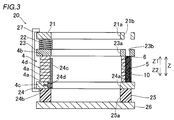
- the jig 20 includes the upper plate 21. Further, as shown in FIG. 3, the jig 20 includes a pressing spring 22, a pressing plate 23, a lower plate 24, a heat insulating member 25, a positioning plate 26, and a clamp member 27.
- the upper plate 21, the pressing plate 23, the lower plate 24, and the positioning plate 26 are each made of SUS (stainless steel).
- the upper plate 21 has a through hole 21a in the central portion and is formed in an annular shape. Further, the upper plate 21 includes a plurality of resin injection holes 21b.
- the resin injection hole 21b is provided so that a nozzle 103a (see FIG. 7) of the resin injection device 103, which will be described later, can be inserted.
- the resin injection holes 21b are provided so as to overlap each of the plurality of magnet accommodating portions 10 (32 in the present embodiment).
- the induction heating coil 102a (see FIG. 7) of the preheating heating device 102 (see FIG. 5) described later passes through the through hole 21a of the upper plate 21 and the through hole 23a of the pressing plate 23 described later. , Is inserted inside the laminated core 4d in the radial direction.
- the induction heating coil provided in the curing heating device 104 is also laminated through the through hole 21a of the upper plate 21 and the through hole 23a of the pressing plate 23 described later. It is inserted inside the core 4d in the radial direction.
- the pressing spring 22 is provided between the upper plate 21 and the pressing plate 23. Further, a plurality of pressing springs 22 are provided at equal angular intervals along the circumferential direction when viewed from the rotation axis C1 direction. In this embodiment, four pressing springs 22 are provided. Each of the plurality of pressing springs 22 is provided at a position where the laminated core 4d is arranged on the jig 20 and overlaps with the laminated core 4d when viewed from above (Z1 direction side).
- the pressing plate 23 is arranged on the upper end surface 4b of the laminated core 4d.
- the pressing plate 23 is provided so as to press the upper end surface 4b of the laminated core 4d by the urging force of the pressing spring 22.
- the pressing plate 23 has a through hole 23a in the central portion and is formed in an annular shape. Further, the pressing plate 23 includes a plurality of resin injection holes 23b. The plurality of resin injection holes 23b are provided at positions that overlap with the plurality of resin injection holes 21b of the upper plate 21 when viewed from above (Z1 direction side). The plurality of resin injection holes 23b are provided so that the nozzle 103a (see FIG. 7) of the resin injection device 103, which will be described later, can be inserted.
- the laminated core 4d is arranged (mounted) on the lower plate 24. That is, the lower plate 24 is in contact with the lower end surface 4c of the laminated core 4d.
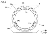
- the lower plate 24 has a through hole 24a in the center and is formed in an annular shape. Further, the lower plate 24 includes a plurality of (three in this embodiment) notches 24b. The plurality of cutout portions 24b are provided at substantially equal angular intervals (see FIG. 4) on the inner peripheral edge of the through hole 24a.
- Each of the plurality of cutout portions 24b is provided with an L-shaped positioning portion 24c.
- the plurality of positioning portions 24c determine the radial and circumferential positions of the laminated core 4d with respect to the lower plate 24.
- the positioning portion 24c is fixed (fastened) to the lower plate 24 by the fastening bolt 24d.
- the heat insulating member 25 is provided so as to be sandwiched between the lower plate 24 and the positioning plate 26.
- the heat insulating member 25 has a through hole 25a in the center and is formed in an annular shape. Further, the heat insulating member 25 is made of resin.
- the positioning plate 26 is provided on the lower side (Z2 direction side) of the lower plate 24.
- the positioning plate 26 is used for positioning the jig 20 in each of the devices (101 to 104) described later.
- the clamp member 27 has a U-shape and is provided so as to sandwich the upper plate 21 and the lower plate 24. As a result, the upper plate 21 and the lower plate 24 sandwich and press the laminated core 4d in the vertical direction (Z direction). The upper plate 21 indirectly sandwiches and presses the laminated core 4d with the lower plate 24 via the pressing plate 23. As a result, the laminated core 4d is fixed to the jig 20.
- a plurality of clamp members 27 (four in this embodiment) are provided. The plurality of clamp members 27 are provided at substantially equal angular intervals (that is, 90 degree intervals) along the circumferential direction when viewed from the rotation axis C1 direction.
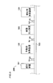
- the rotor core 4 manufacturing system 200 includes an assembly device 101, a preheating heating device 102, a resin injection device 103, and a curing heating device 104. Further, the rotor core 4 manufacturing system 200 includes a conveyor 105 for transporting the laminated core 4d.
- the assembly device 101, the preheating heating device 102, the resin injection device 103, and the curing heating device 104 are separate devices from each other. Further, the conveyor 105 for transport is an example of the "conveyor mechanism" and the "moving mechanism" in the claims.
- the assembly device 101 is configured to arrange (assemble) the laminated core 4d on the jig 20. Specifically, the assembling device 101 is configured to arrange the laminated core 4d on the jig 20 and arrange (insert) the permanent magnet 5 in the magnet accommodating portion 10.
- the preheating heating device 102 is configured to preheat by heating the laminated core 4d. Specifically, the preheating heating device 102 heats the laminated core 4d arranged on the jig 20 at a first temperature T1 (for example, 50 ° C.) or higher and lower than a second temperature T2 (for example, 120 ° C.). It is configured to be preheated by.
- the first temperature T1 is the temperature at which the resin material 6 melts (the temperature at which melting starts).
- the second temperature T2 is a temperature at which the resin material 6 is cured (thermosetting) (a temperature at which curing (thermosetting) is started) and is higher than the first temperature T1.
- the resin injection device 103 is configured to inject the resin material 6 into the magnet accommodating portion 10. Specifically, the resin injection device 103 is first placed in the magnet accommodating portion 10 in a state where the laminated core 4d is arranged in the jig 20 and in a state where the permanent magnet 5 is inserted in the magnet accommodating portion 10. It is configured to inject the resin material 6 melted at a temperature T1 or higher.
- the curing heating device 104 is configured to cure the resin material 6 in the magnet accommodating portion 10 by heating the laminated core 4d. Specifically, the curing heating device 104 is the temperature at which the resin material 6 cures the laminated core 4d in a state where the resin material 6 is injected into the magnet accommodating portion 10 while being arranged on the jig 20. It is configured to cure the resin material 6 in the magnet accommodating portion 10 by heating at the second temperature T2 or higher.
- the transport conveyor 105 is a laminated core 4d in a state of being arranged on the jig 20 and in which the resin material 6 is injected into the magnet accommodating portion 10 from the resin injection device 103. It is configured to be moved (conveyed) to the curing heating device 104.
- the conveyor 105 is configured to convey the laminated core 4d arranged on the jig 20 in the order of the assembly device 101, the preheating heating device 102, the resin injection device 103, and the curing heating device 104. ing.
- the transport conveyor 105 is stopped while the manufacturing process is being executed in each device, and is restarted when the manufacturing process is completed in each device so that the laminated core 4d is transported to the device in the next process. It is configured in.
- the rotor core 4 manufacturing system 200 is configured to simultaneously convey a plurality of laminated cores 4d arranged in a row by a transfer conveyor 105.
- a transfer conveyor 105 For example, when one laminated core 4d is arranged in the curing heating device 104, the subsequent laminated core 4d is arranged in the resin injection device 103. That is, the plurality of laminated cores 4d arranged side by side in a row are provided in different devices.
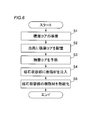
- step S1 a step of preparing the laminated core 4d is performed.
- the laminated core 4d is formed by laminating a plurality of electromagnetic steel sheets 4a.
- the magnet accommodating portion 10 extending in the stacking direction of the electromagnetic steel sheet 4a is formed in the laminated core 4d by press working.
- step S2 a step of arranging the laminated core 4d on the jig 20 is performed in the assembly device 101.
- the laminated core 4d is arranged on the jig 20 so that the laminated core 4d is sandwiched and pressed in the vertical direction (Z direction) by the upper plate 21 (pressing plate 23) and the lower plate 24. ..
- a step of arranging (mounting) the laminated core 4d on the lower plate 24 is performed.
- a step of arranging the permanent magnet 5 in the magnet accommodating portion 10 is performed with the laminated core 4d arranged on the lower plate 24.
- step S2 is a step of arranging the laminated core 4d on the jig 20 provided with the heat insulating member 25.
- step S3 a step of preheating the laminated core 4d is performed. Specifically, in the preheating heating device 102, a step of preheating the laminated core 4d arranged on the jig 20 by heating at a first temperature T1 or more and a second temperature T2 or less is performed.
- the method for manufacturing the rotor core 4 includes a step of moving the laminated core 4d arranged on the jig 20 by transporting it from the assembly device 101 to the resin injection device 103 by the transport conveyor 105.
- this step includes a step of moving the laminated core 4d by transporting the laminated core 4d from the assembly device 101 to the preheating heating device 102 by the transport conveyor 105 (a step between steps S2 and S3) and transport.
- a step (a step between steps S3 and S4) of moving the laminated core 4d by transporting the laminated core 4d from the preheating heating device 102 to the resin injection device 103 by the conveyor 105 is included.
- step S4 a step of injecting the resin material 6 into the magnet accommodating portion 10 is performed. Specifically, in the state where the laminated core 4d is arranged in the jig 20, and the permanent magnet 5 is inserted in the magnet accommodating portion 10, in the resin injection device 103, the first magnet accommodating portion 10 is inserted. A step of injecting the molten resin material 6 at a temperature T1 or higher is performed.
- the step of injecting the resin material 6 into the magnet accommodating portion 10 in the resin injection device 103 is that the resin injection device 103 is heated at a first temperature T1 or more and less than a second temperature T2.
- the resin injection device 103 is configured to be capable of melting the resin material 6 held in the resin injection device 103 in a solid state by a heating heater or the like provided in the resin injection device 103 and changing the resin material 6 into a liquid state. Has been done.
- the resin injection device 103 is a laminated core 4d in which the resin material 6 is injected into the magnet accommodating portion 10 while being arranged on the jig 20 by the transport conveyor 105.
- a step (step between step S4 and step S5) of moving the magnet by transporting it to the curing heating device 104 is provided. That is, the laminated core 4d is conveyed from the resin injection device 103 to the curing heating device 104 different from the resin injection device 103 while the pressed state by the jig 20 is maintained.
- the step of moving the laminated core 4d from the assembly device 101 to the preheating heating device 102 the step of moving the laminated core 4d from the preheating heating device 102 to the resin injection device 103, and the step of moving the laminated core 4d to the resin injection device 103, and the laminated core 4d.
- the laminated core 4d is assembled by the conveying conveyor 105 while maintaining the state in which the laminated core 4d is arranged on the same jig 20.
- the step includes a step of moving the preheating heating device 102, the resin injection device 103, and the curing heating device 104 by transporting them in this order.
- the laminated core 4d is not removed from the jig 20 even once after being arranged on the jig 20 in the assembly device 101, and the assembly device 101, the preheating heating device 102, the resin injection device 103, and the curing heating It is conveyed in the order of the device 104.
- the jig 20 provided with the heat insulating member 25 is used.
- step S5 a step of thermosetting the resin material 6 of the magnet accommodating portion 10 is performed by heating the laminated core 4d.
- the laminated core 4d arranged on the jig 20 and in which the resin material 6 is injected into the magnet accommodating portion 10 is heated at the second temperature T2 or higher in the curing heating device 104.
- the step of curing the resin material 6 in the magnet accommodating portion 10 is performed. Even in this step, the heat insulating effect of the heat insulating member 25 on the positioning plate 26 is maintained.
- the method for manufacturing the rotor core (4) is that the laminated core (4d) is arranged on the jig (20) and the permanent magnet (5) is inserted in the magnet accommodating portion (10).
- the resin injection device (103) includes a step of injecting the molten resin material (6) into the magnet accommodating portion (10). Further, in the method of manufacturing the rotor core (4), a laminated core (4d) in a state of being arranged on the jig (20) and in a state of being injected with the resin material (6) into the magnet accommodating portion (10) is used. A step of moving the resin injection device (103) to a curing heating device (104), which is a device separate from the resin injection device (103), is provided. Further, in the method of manufacturing the rotor core (4), after the step of moving the laminated core (4d) to the curing heating device (104), the rotor core (4) is arranged in the jig (20) and the magnet accommodating portion (10). ), The laminated core (4d) in which the resin material (6) is injected is heated by the curing heating device (104) to cure the resin material (6) in the magnet accommodating portion (10). To be equipped with.
- the injection step of the resin material (6) and the curing step of the resin material (6) are executed in separate devices, it is possible to prevent the occupancy time of the resin injection device (103) from becoming excessively long. Can be done. That is, when a plurality of rotor cores (4) are continuously manufactured on a production line in which the steps in the plurality of devices are sequentially performed, the laminated core (4d) that has completed the steps prior to the resin injection step is resin-injected. It is possible to prevent the waiting time from becoming excessively long when shifting to the process.
- the manufacturing time of the rotor cores (4) can be shortened, so that a decrease in the productivity of the rotor cores (4) can be suppressed.
- the laminated core (4d) moves from the resin injection device (103) to the curing heating device (104) in a state of being arranged on the jig (20), the resin material (6) becomes an electromagnetic steel plate during the movement. (4a) It is possible to prevent leakage from between the two.
- the step of moving the laminated core (4d) to the curing heating device (104) is in a state of being arranged on the jig (20) and in the magnet accommodating portion (10). ),
- the laminated core (4d) in which the resin material (6) is injected is transferred from the resin injection device (103) to the curing heating device (104) by the transfer conveyor (105) to move the laminated core (4d).
- the transfer mechanism (105) can automate the process of transferring the laminated core (4d) from the resin injection device (103) to the curing heating device (104). As a result, the human labor required for manufacturing the rotor core (4) can be reduced.
- the resin material (6) melts at the first temperature (T1) or higher and is cured at the second temperature (T2) or higher, which is larger than the first temperature (T1). It is configured as follows. Further, in the step of injecting the resin material (6) into the magnet accommodating portion (10) in the resin injection device (103), the resin injection device (103) is heated at the first temperature (T1) or more and less than the second temperature (T2). This is a step of injecting the resin material (6) melted from the solid state to the liquid state into the magnet accommodating portion (10) by the resin injection device (103).
- the resin material (6) is heated at the second temperature (T2) or higher in the curing heating device (104), so that the resin material in the magnet accommodating portion (10) is cured.
- T2 the second temperature
- the resin injection device (6) is heated below the second temperature (T2), which is the temperature at which the resin material (6) is cured, so that the resin injection device (6) is heated.
- T2 the second temperature
- the resin material (6) remaining in the resin injection device (103) is not used and is discarded. Therefore, by preventing the cured residual resin from being formed in the resin injection device (103), the efficiency of use of the resin material (6) can be improved (yield can be improved).
- the step of arranging the laminated core (4d) on the jig (20) is a device separate from the resin injection device (103) and the curing heating device (104). This is a step of arranging the laminated core (4d) on the jig (20) in the assembling device (101).
- the method for manufacturing the rotor core (4) includes a step of moving the laminated core (4d) arranged on the jig (20) from the assembly device (101) to the resin injection device (103). Further, a step of moving the laminated core (4d) from the assembling device (101) to the resin injection device (103), and moving the laminated core (4d) from the resin injection device (103) to the curing heating device (104).
- the laminated core (4d) is assembled into an assembling device (101), a resin injection device (103), and a heating device for curing (10d).
- the step of moving in the order of 104) is included.
- the step of assembling the laminated core (4d) to the jig (20), the step of injecting the resin material (6), and the step of curing the resin material (6) are executed in separate devices from each other. Therefore, it is possible to prevent the occupancy time of the assembly device (101), the resin injection device (103), and the curing heating device (104) from becoming excessively long.
- the manufacturing time of the rotor core (4) can be further shortened. Further, while maintaining the state in which the laminated core (4d) is arranged on the same jig (20), the laminated core (4d) is assembled into the assembling device (101), the resin injection device (103), and the curing heating device (104). ), It is possible to prevent the number of types of the jig (20) from increasing, and the rotor core (4) does not need to be removed from the jig (20). It is possible to prevent the manufacturing time of the product from becoming long.
- the method for manufacturing the rotor core (4) is after the step of arranging the laminated core (4d) on the jig (20) in the assembly device (101) and injecting resin.
- an apparatus separate from the assembling apparatus (101), the resin injecting apparatus (103), and the curing heating apparatus (104).
- the preheating heating device (102) is provided with a step of preheating by heating the laminated core (4d) arranged on the jig (20).
- the step of moving the laminated core (4d) from the assembling device (101) to the resin injection device (103) is a step of moving the laminated core (4d) from the assembling device (101) to the preheating heating device (102).
- the step of moving the laminated core (4d) from the preheating heating device (102) to the resin injection device (103) is included.
- a step of moving the laminated core (4d) from the assembling device (101) to the preheating heating device (102), a step of moving the laminated core (4d) from the preheating heating device (102) to the resin injection device (103), and The step of moving the laminated core (4d) from the resin injection device (103) to the curing heating device (104) is performed while maintaining the state in which the laminated core (4d) is arranged on the same jig (20).
- the step of moving the laminated core (4d) in the order of the assembling device (101), the preheating heating device (102), the resin injection device (103), and the curing heating device (104) is included.
- the step of assembling the laminated core (4d) to the jig (20), the step of preheating the laminated core (4d), the step of injecting the resin material (6), and the curing of the resin material (6) Since the steps can be performed in separate devices, the occupancy time of the assembly device (101), preheating heating device (102), resin injection device (103), and curing heating device (104) is excessively long. It can be prevented from becoming. As a result, when a plurality of rotor cores (4) are continuously manufactured, the manufacturing time of the rotor cores (4) can be further shortened.
- the laminated core (4d) is assembled into an assembly device (101), a preheating heating device (102), and a resin injection device (103).
- the curing heating device (104) in this order, it is possible to prevent the types of the jig (20) from increasing, and it is necessary to remove the laminated core (4d) from the jig (20). It is possible to more effectively prevent the manufacturing time of the rotor core (4) from becoming longer due to the absence of the rotor core (4).
- the laminated core (4d) is brought into a high temperature state when the resin material (6) is injected into the magnet accommodating portion (10). Can be done. As a result, the resin material (6) can be easily injected into the magnet accommodating portion (10).
- the laminated core (4d) is assembled in the order of the assembly device (101), the preheating heating device (102), the resin injection device (103), and the curing heating device (104).
- the assembly device (101), the preheating heating device (102), and the resin injection device (103) are used.
- the curing heating device (104) in this order.
- the transfer mechanism (105) can automate the transfer from the assembly device (101) to the curing heating device (104).
- the human labor required for manufacturing the rotor core (4) can be further reduced.
- the laminated core (4d) is placed on the jig (20) provided with the heat insulating member (25). This is the process of arranging. Further, the step of moving the laminated core (4d) in the order of the assembly device (101), the preheating heating device (102), the resin injection device (103), and the curing heating device (104) is the heat insulating member (25).
- the laminated core (4d) arranged on the jig (20) provided with the above is used in the assembling device (101), the preheating heating device (102), the resin injection device (103), and the curing heating device (104). This is the process of moving in order.
- the heat insulating member (25) prevents the jig (20) from being heated and deteriorated (damaged) due to the heat from the laminated core (4d) being transferred to the jig (20). be able to. Further, the heat insulating member (25) can maintain the heat of the preheated (preheated) laminated core (4d) until the laminated core (4d) moves to the resin injection device (103).
- the laminated core (4d) is arranged on the jig (20) that presses the laminated core (4d) in the laminating direction. Resin injection that injects the molten resin material (6) into the magnet housing (10) of the laminated core (4d) in this state and with the permanent magnet (5) inserted in the magnet housing (10). The device (103) is provided. Further, the rotor core (4) manufacturing system heats the laminated core (4d) in a state of being arranged on the jig (20) and in a state where the resin material (6) is injected into the magnet accommodating portion (10).
- a curing heating device (104) for curing the resin material (6) in the magnet accommodating portion (10) is provided. Further, in the rotor core (4) manufacturing system, the laminated core (4d) is arranged in the jig (20) and the resin material (6) is injected into the magnet accommodating portion (10). A moving mechanism (105) for moving the resin injection device (103) to the curing heating device (104) is provided.
- the step of arranging the laminated core (4d) on the jig (20) is included in the upper plate (21) and the jig (20) included in the jig (20).
- This is a step of arranging the laminated core (4d) on the jig (20) so that the laminated core (4d) is sandwiched and pressed in the vertical direction by the lower plate (24).
- the laminated core (4d) is sandwiched and pressed by the upper plate (21) and the lower plate (24), so that the laminated core (4d) can be stably fixed to the jig (20). it can.
- the injection step of the resin material (6) and the curing step of the resin material (6) are executed in separate devices, it is possible to prevent the occupancy time of the resin injection device (103) from becoming excessively long. Can be done. That is, when a plurality of rotor cores (4) are continuously manufactured on a production line in which the steps in the plurality of devices are sequentially performed, the laminated core (4d) that has completed the steps prior to the resin injection step is resin-injected. It is possible to prevent the waiting time from becoming excessively long when shifting to the process.
- a manufacturing system (200) for the rotor core (4) can be provided. Further, since the moving mechanism (105) moves the laminated core (4d) arranged on the jig (20) from the resin injection device (103) to the curing heating device (104), the resin material is moved during the movement. It is possible to provide a rotor core (4) manufacturing system (200) capable of preventing the (6) from leaking between the electromagnetic steel plates (4a).
- the moving mechanism (105) includes the transport conveyor (105).
- the transfer of the laminated core (4d) from the resin injection device (103) to the curing heating device (104) can be automated by the transfer conveyor (105).
- the human labor required for manufacturing the rotor core (4) can be reduced.
- the laminated core 4d is conveyed by the conveyor 105 (conveyor mechanism, moving mechanism)
- the present invention is not limited to this.
- the laminated core 4d may be moved by an operator (manually).
- the laminated core 4d is conveyed by the transfer conveyor 105 (movement mechanism, transfer mechanism)
- the laminated core 4d may be moved by a moving mechanism (for example, a robot arm) other than the transport conveyor 105.
- the assembly device 101, the preheating heating device 102, and the resin injection device 103 are separate devices from each other, but the present invention is not limited to this.
- the steps performed in the assembly device 101, the preheating heating device 102, and the resin injection device 103 may be configured to be performed in one device.
- preheating heating device 102 and the curing heating device 104 are separate devices from each other, but the present invention is not limited to this.
- the preheating heating device 102 and the curing heating device 104 may be the same device.
- Rotor core 4a Electromagnetic steel plate 4d Laminated core 5 Permanent magnet 6 Resin material 10 Magnet accommodating part 20 Jig 21 Upper plate 24 Lower plate 25 Insulation member 101 Assembly device 102 Preheating heating device 103 Resin injection device 104 Curing heating device 105 For transportation Conveyor (conveyor mechanism, moving mechanism) 200 Manufacturing System (Rotor Core Manufacturing System) T1 1st temperature T2 2nd temperature
Landscapes
- Engineering & Computer Science (AREA)
- Power Engineering (AREA)
- Manufacturing & Machinery (AREA)
- Mechanical Engineering (AREA)
- Manufacture Of Motors, Generators (AREA)
- Permanent Field Magnets Of Synchronous Machinery (AREA)
Abstract
このロータコアの製造方法は、治具に配置された状態で、かつ、磁石収容部に樹脂材が注入された状態の積層コアを、樹脂注入装置から、樹脂注入装置とは別個の装置である硬化用加熱装置に移動させる工程と、積層コアを硬化用加熱装置において加熱することによって、磁石収容部内の樹脂材を硬化させる工程とを備える。
Description
本発明は、ロータコアの製造方法およびロータコアの製造システムに関する。
従来、永久磁石が挿入される磁石収容部に樹脂材を注入するロータコアの製造方法およびロータコアの製造システムが知られている。このようなロータコアの製造方法およびロータコアの製造システムは、たとえば、特許第6180569号公報に開示されている。
上記特許第6180569号公報には、複数枚の鉄心片が積層された回転子積層鉄心の複数の磁石挿入孔の各々に永久磁石を挿入し、各磁石挿入穴に永久磁石を樹脂封止する方法が開示されている。具体的には、上記特許第6180569号公報には、樹脂を加熱して溶融させるとともに溶融された樹脂を回転子積層鉄心の磁石挿入孔に供給することが可能な樹脂封止装置が開示されている。樹脂封止装置には、回転子積層鉄心を(回転子積層鉄心の軸方向に)挟み込むことにより回転子積層鉄心を押圧可能に構成された上型および下型が設けられている。
また、樹脂封止装置は、上型および下型により回転子積層鉄心を押圧した状態で、樹脂封止装置内に保持された樹脂を加熱して溶融させるとともに、溶融した樹脂を回転子積層鉄心の磁石挿入孔の各々に供給するように構成されている。これにより、回転子積層鉄心の磁石挿入穴に供給された樹脂が、電磁鋼板同士の間から漏れるのが抑制されている。そして、樹脂封止装置は、各磁石挿入穴に樹脂が充填された後も加熱状態を所定の時間維持することによって、各磁石挿入穴の樹脂を熱硬化させるように構成されている。
しかしながら、上記特許第6180569号公報に記載のロータコア(回転子積層鉄心)の製造方法では、各磁石挿入穴への樹脂の供給工程および樹脂の熱硬化工程の各々が、同一の樹脂封止装置において行われている。このため、樹脂封止装置の占有時間が過度に長くなる場合がある。この場合、複数の装置における工程が順番に行われる製造ライン上において複数のロータコアを連続で製造する場合に、樹脂封止装置の前の工程を終えた積層コアが樹脂封止装置における工程に移行する際の待機時間が長くなるという不都合がある。このため、複数のロータコアの製造に要する時間が長くなるため、生産性が低下するという問題点がある。
この発明は、上記のような課題を解決するためになされたものであり、この発明の1つの目的は、連続的に複数のロータコアを製造する場合に、ロータコアの生産性の低下を抑制することが可能なロータコアの製造方法およびロータコアの製造システムを提供することである。
上記目的を達成するために、この発明の第1の局面におけるロータコアの製造方法は、複数の電磁鋼板が積層され、電磁鋼板の積層方向に延びる磁石収容部を有する積層コアを準備する工程と、磁石収容部に永久磁石を配置する工程と、積層コアを積層方向に押圧する治具に、積層コアを配置する工程と、治具に積層コアが配置された状態で、かつ、磁石収容部に永久磁石が挿入された状態で、樹脂注入装置において、磁石収容部に、溶融した樹脂材を注入する工程と、治具に配置された状態で、かつ、磁石収容部に樹脂材が注入された状態の積層コアを、樹脂注入装置から、樹脂注入装置とは別個の装置である硬化用加熱装置に移動させる工程と、積層コアを硬化用加熱装置に移動させる工程の後、治具に配置された状態で、かつ、磁石収容部に樹脂材が注入された状態の積層コアを、硬化用加熱装置において加熱することによって、磁石収容部内の樹脂材を硬化させる工程と、を備える。
この発明の第1の局面によるロータコアの製造方法は、上記のように、治具に配置された状態の積層コアを樹脂注入装置から硬化用加熱装置に移動させる工程と、治具に配置された状態の積層コアを樹脂注入装置とは別個の硬化用加熱装置において加熱することによって磁石収容部内の樹脂材を硬化させる工程とを備える。これにより、樹脂材の注入工程および樹脂材の硬化工程が互いに別個の装置において実行されるので、樹脂注入装置の占有時間が過度に長くなるのを防止することができる。すなわち、複数の装置における工程が順番に行われる製造ライン上において連続的に複数のロータコアを製造する場合に、樹脂注入工程の前の工程を終えた積層コアが、樹脂注入工程に移行する際に、待機時間が過度に長くなるのを防止することができる。これにより、連続的に複数のロータコアを製造する場合に、ロータコアの製造時間を短縮化することができるので、ロータコアの生産性の低下を抑制することができる。また、積層コアは、治具に配置された状態で樹脂注入装置から硬化用加熱装置に移動するので、移動中に樹脂材が電磁鋼板同士の間から漏れるのを防止することができる。
この発明の第2の局面におけるロータコアの製造システムは、複数の電磁鋼板が積層され、電磁鋼板の積層方向に延びる磁石収容部を有するロータコアの製造システムであって、積層コアを積層方向に押圧する治具に積層コアが配置された状態で、かつ、磁石収容部に永久磁石が挿入された状態で、積層コアの磁石収容部に、溶融した樹脂材を注入する樹脂注入装置と、治具に配置された状態で、かつ、磁石収容部に樹脂が注入された状態の積層コアを加熱することによって、磁石収容部内の樹脂材を硬化させる硬化用加熱装置と、治具に配置された状態で、かつ、磁石収容部に樹脂材が注入された状態の積層コアを、樹脂注入装置から硬化用加熱装置に移動させる移動機構と、を備える。
この発明の第2の局面によるロータコアの製造システムでは、上記のように、ロータコアの製造システムは、治具に配置された状態の積層コアを樹脂注入装置から硬化用加熱装置に移動させる移動機構と、樹脂注入装置とは別個に設けられ、治具に配置された状態の積層コアを加熱することによって磁石収容部内の樹脂材を硬化させる硬化用加熱装置と、を備える。これにより、樹脂材の注入工程および樹脂材の硬化工程が互いに別個の装置において実行されるので、樹脂注入装置の占有時間が過度に長くなるのを防止することができる。すなわち、複数の装置における工程が順番に行われる製造ライン上において連続的に複数のロータコアを製造する場合に、樹脂注入工程の前の工程を終えた積層コアが、樹脂注入工程に移行する際に、待機時間が過度に長くなるのを防止することができる。これにより、連続的に複数のロータコアを製造する場合に、ロータコアの製造時間を短縮化することができるので、ロータコアの生産性の低下を抑制することが可能なロータコアの製造システムを提供することができる。また、移動機構は、治具に配置された状態の積層コアを樹脂注入装置から硬化用加熱装置に移動させるので、移動中に樹脂材が電磁鋼板同士の間から漏れるのを防止することが可能なロータコアの製造システムを提供することができる。
本発明によれば、連続的に複数のロータコアを製造する場合に、ロータコアの生産性の低下を抑制することができる。
以下、本発明の実施形態を図面に基づいて説明する。
[本実施形態]
図1~図7を参照して、本実施形態によるロータコア4の製造方法およびロータコア4の製造システムについて説明する。
図1~図7を参照して、本実施形態によるロータコア4の製造方法およびロータコア4の製造システムについて説明する。
本願明細書では、「軸方向」とは、ロータ1(ロータコア4)の回転軸線C1に沿った方向を意味し、図中のZ方向を意味する。また、「積層方向」とは、ロータコア4の電磁鋼板4a(図3参照)が積層する方向を意味し、図中のZ方向を意味する。また、「径方向」とは、ロータ1(ロータコア4)の径方向(R1方向またはR2方向)を意味し、「周方向」は、ロータ1(ロータコア4)の周方向(E1方向またはE2方向)を意味する。
(ロータコアの構造)
まず、図1を参照して、本実施形態のロータコア4の構造について説明する。
まず、図1を参照して、本実施形態のロータコア4の構造について説明する。
図1に示すように、回転電機100は、ロータ1とステータ2とを備える。また、ロータ1およびステータ2は、それぞれ、円環状に形成されている。そして、ロータ1は、ステータ2の径方向内側に対向して配置されている。すなわち、本実施形態では、回転電機100は、インナーロータ型の回転電機として構成されている。また、ロータ1の径方向内側には、シャフト3が配置されている。シャフト3は、ギア等の回転力伝達部材を介して、エンジンや車軸に接続されている。たとえば、回転電機100は、モータ、ジェネレータ、または、モータ兼ジェネレータとして構成されており、車両に搭載されるように構成されている。
また、ロータコア4は、複数の電磁鋼板4a(図3参照)が積層され、電磁鋼板4aの積層方向に延びる磁石収容部10を有する積層コア4dを備える。また、ロータコア4は、積層コア4dの磁石収容部10に挿入される永久磁石5を備える。磁石収容部10は、積層コア4dに複数(本実施形態では32個)設けられている。すなわち、回転電機100は、埋込永久磁石型モータ(IPMモータ:Interior Permanent Magnet Motor)として構成されている。また、磁石収容部10は、積層コア4d(ロータコア4)のうちの径方向外側の部分に配置されている。すなわち、磁石収容部10と積層コア4d(ロータコア4)の外周面40との距離は、磁石収容部10と積層コア4d(ロータコア4)の後述する内周面4eとの距離よりも小さい。なお、互いに隣接する2つの磁石収容部10は、V字状に配置されている。なお、磁石収容部10の配置は、これに限られない。
また、ステータ2は、ステータコア2aと、ステータコア2aに配置されたコイル2bとを含む。ステータコア2aは、たとえば、複数の電磁鋼板(珪素鋼板)が軸方向に積層されており、磁束を通過可能に構成されている。コイル2bは、外部の電源部に接続されており、電力(たとえば、3相交流の電力)が供給されるように構成されている。そして、コイル2bは、電力が供給されることにより、磁界を発生させるように構成されている。また、ロータ1およびシャフト3は、コイル2bに電力が供給されない場合でも、エンジン等の駆動に伴って、ステータ2に対して回転するように構成されている。なお、図1では、コイル2bの一部のみを図示しているが、コイル2bは、ステータコア2aの全周に亘って配置されている。
永久磁石5は、積層コア4d(ロータコア4)の軸方向に直交する断面が長方形形状を有している。たとえば、永久磁石5は、磁化方向(着磁方向)が短手方向となるように構成されている。
また、ロータコア4は、磁石収容部10に充填されている樹脂材6(図3参照)を備える。樹脂材6は、磁石収容部10に配置されている永久磁石5を固定するように設けられている。樹脂材6は、第1温度T1において溶融するとともに第1温度T1よりも高い第2温度T2において硬化する材料(熱硬化性樹脂)により構成されている。詳細には、樹脂材6は、第1温度T1よりも低い常温において固形(フレーク状、ペレット状、または、粉状など)であり、常温から加熱されて、樹脂材6の温度が第1温度T1以上になると溶融する。そして、樹脂材6は、第1温度T1以上でかつ第2温度T2未満の状態では、溶融状態を維持する(硬化しない)ように構成されている。そして、樹脂材6は、第2温度T2以上の温度に加熱されることにより、硬化するように構成されている。なお、図1では、簡略化のため、樹脂材6の図示を省略している。
たとえば、樹脂材6として、特開2000-239642号公報に記載されているような合成樹脂材を用いることが可能である。すなわち、樹脂材6は、ウレトジオン環を100eq/T以上有する第1化合物を10%以上100%以下と、分子末端に活性水素基を有する第2化合物を0%以上90%以下と、グリシジル基を有する第3化合物を0%以上90%以下とを含有し、かつ、第1~第3化合物のいずれにも分子末端にイソシアネート基を含まないことを特徴とする反応性ホットメルト接着剤組成物を含む。
(治具の構造)
次に、図2~図4を参照して、本実施形態の治具20の構造について説明する。なお、以下の説明では、治具20に積層コア4dが配置された状態についての治具20の構造について説明する。
次に、図2~図4を参照して、本実施形態の治具20の構造について説明する。なお、以下の説明では、治具20に積層コア4dが配置された状態についての治具20の構造について説明する。
図2に示すように、治具20は、上方プレート21を含む。また、図3に示すように、治具20は、押圧ばね22と、押圧プレート23と、下方プレート24と、断熱部材25と、位置決めプレート26と、クランプ部材27と、を含む。なお、上方プレート21、押圧プレート23、下方プレート24、および位置決めプレート26の各々は、SUS(ステンレス)製である。
図2に示すように、上方プレート21は、中心部に貫通孔21aを有し、円環状に形成されている。また、上方プレート21は、複数の樹脂注入孔21bを含む。樹脂注入孔21bは、後述する樹脂注入装置103のノズル103a(図7参照)が挿入可能に設けられている。なお、樹脂注入孔21bは、複数(本実施形態では32個)の磁石収容部10の各々とオーバラップするように設けられている。
なお、後述する予熱用加熱装置102(図5参照)の誘導加熱コイル102a(図7参照)は、上方プレート21の貫通孔21a、および、後述する押圧プレート23の貫通孔23aの各々を介して、積層コア4dの径方向内側に挿入される。また、図示は省略するが、硬化用加熱装置104に設けられる誘導加熱コイルも、同様に、上方プレート21の貫通孔21a、および、後述する押圧プレート23の貫通孔23aの各々を介して、積層コア4dの径方向内側に挿入される。
押圧ばね22は、上方プレート21と、押圧プレート23との間に設けられている。また、押圧ばね22は、回転軸線C1方向から見て、周方向に沿って、等角度間隔に複数設けられている。なお、本実施形態では、押圧ばね22は、4つ設けられている。複数の押圧ばね22の各々は、治具20に積層コア4dが配置された状態で、上方(Z1方向側)から見て、積層コア4dとオーバラップする位置に設けられている。
また、図3に示すように、押圧プレート23は、積層コア4dの上端面4bに配置されている。押圧プレート23は、押圧ばね22の付勢力により、積層コア4dの上端面4bを押圧するように設けられている。
また、押圧プレート23は、中心部に貫通孔23aを有し、円環状に形成されている。また、押圧プレート23は、複数の樹脂注入孔23bを含む。複数の樹脂注入孔23bは、上方(Z1方向側)から見て、上方プレート21の複数の樹脂注入孔21bとオーバラップする位置に設けられている。なお、複数の樹脂注入孔23bは、後述する樹脂注入装置103のノズル103a(図7参照)が挿入可能に設けられている。
また、積層コア4dは、下方プレート24に配置(載置)されている。すなわち、下方プレート24は、積層コア4dの下端面4cと接触している。下方プレート24は、中心部に貫通孔24aを有し、円環状に形成されている。また、下方プレート24は、複数(本実施形態では3つ)の切り欠き部24bを含む。複数の切り欠き部24bは、貫通孔24aの内周縁において、略等角度間隔(図4参照)で設けられている。
複数の切り欠き部24bの各々には、L字状の位置決め部24cが設けられている。複数の位置決め部24cにより、下方プレート24に対する積層コア4dの径方向および周方向の位置が決められる。位置決め部24cは、締結ボルト24dにより、下方プレート24に固定(締結)されている。
また、断熱部材25は、下方プレート24と、位置決めプレート26との間に挟まれるように設けられている。断熱部材25は、中心部に貫通孔25aを有し、円環状に形成されている。また、断熱部材25は、樹脂製である。
また、位置決めプレート26は、下方プレート24の下方側(Z2方向側)に設けられている。位置決めプレート26は、後述する各装置(101~104)における治具20の位置決めに用いられる。
また、クランプ部材27は、U字形状を有しており、上方プレート21と下方プレート24とを挟み込むように設けられている。これにより、上方プレート21と下方プレート24とが、積層コア4dを、上下方向(Z方向)に挟み込むとともに押圧する。なお、上方プレート21は、押圧プレート23を介して間接的に積層コア4dを、下方プレート24とにより挟み込むとともに押圧している。その結果、治具20に積層コア4dが固定される。クランプ部材27は、複数(本実施形態では4つ)設けられている。複数のクランプ部材27は、回転軸線C1方向から見て、周方向に沿って、略等角度間隔(すなわち90度間隔)に設けられている。
(ロータコアの製造システム)
次に、図5を参照して、ロータコア4の製造システム200について説明する。
次に、図5を参照して、ロータコア4の製造システム200について説明する。
図5に示すように、ロータコア4の製造システム200は、組立装置101と、予熱用加熱装置102と、樹脂注入装置103と、硬化用加熱装置104と、を備える。また、ロータコア4の製造システム200は、積層コア4dを搬送する搬送用コンベア105を備える。なお、組立装置101、予熱用加熱装置102、樹脂注入装置103、および硬化用加熱装置104は、互いに別個の装置である。また、搬送用コンベア105は、請求の範囲の「搬送機構」および「移動機構」の一例である。
組立装置101は、治具20に積層コア4dを配置する(組み付ける)ように構成されている。具体的には、組立装置101は、治具20に積層コア4dを配置するとともに、永久磁石5を磁石収容部10に配置(挿入)するように構成されている。
予熱用加熱装置102は、積層コア4dを加熱することにより予熱するように構成されている。具体的には、予熱用加熱装置102は、治具20に配置された状態の積層コア4dを、第1温度T1(たとえば50℃)以上第2温度T2(たとえば120℃)未満で加熱することにより予熱するように構成されている。なお、第1温度T1とは、樹脂材6が溶融する温度(溶融が開始される温度)である。また、第2温度T2とは、樹脂材6が硬化(熱硬化)する温度(硬化(熱硬化)が開始される温度)であるとともに第1温度T1よりも大きい温度である。
樹脂注入装置103は、磁石収容部10に樹脂材6を注入するように構成されている。具体的には、樹脂注入装置103は、治具20に積層コア4dが配置された状態で、かつ、磁石収容部10に永久磁石5が挿入された状態で、磁石収容部10に、第1温度T1以上で溶融した樹脂材6を注入するように構成されている。
硬化用加熱装置104は、積層コア4dを加熱することによって、磁石収容部10内の樹脂材6を硬化させるように構成されている。具体的には、硬化用加熱装置104は、治具20に配置された状態で、かつ、磁石収容部10に樹脂材6が注入された状態の積層コア4dを、樹脂材6が硬化する温度である第2温度T2以上で加熱することによって、磁石収容部10内の樹脂材6を硬化させるように構成されている。
ここで、本実施形態では、搬送用コンベア105は、治具20に配置された状態で、かつ、磁石収容部10に樹脂材6が注入された状態の積層コア4dを、樹脂注入装置103から硬化用加熱装置104に移動させる(搬送する)ように構成されている。搬送用コンベア105は、治具20に配置された状態の積層コア4dを、組立装置101、予熱用加熱装置102、樹脂注入装置103、および硬化用加熱装置104の順で搬送するように構成されている。
搬送用コンベア105は、各装置において製造工程が実行されている間は停止するとともに、各装置において製造工程が完了した場合は稼働を再開し、次の工程の装置に積層コア4dを搬送するように構成されている。
また、ロータコア4の製造システム200は、搬送用コンベア105により、列状に並んだ複数の積層コア4dを同時に搬送するように構成されている。これにより、たとえば1つの積層コア4dが硬化用加熱装置104に配置されている場合、後続の積層コア4dは樹脂注入装置103内に配置されている。すなわち、列状に並んで配置される複数の積層コア4dは、互いに異なる装置内に設けられている。
(ロータコアの製造方法)
次に、図6を参照して、ロータコア4の製造方法について説明する。
次に、図6を参照して、ロータコア4の製造方法について説明する。
まず、図6に示すように、ステップS1において、積層コア4dを準備する工程が行われる。具体的には、複数の電磁鋼板4aが積層されることによって、積層コア4dが形成される。この際、プレス加工によって、電磁鋼板4aの積層方向に延びる磁石収容部10が積層コア4dに形成される。
次に、ステップS2において、組立装置101において、治具20に積層コア4dを配置する工程が行われる。この工程では、上方プレート21(押圧プレート23)と下方プレート24とによって、積層コア4dが上下方向(Z方向)に挟み込まれるとともに押圧されるように、積層コア4dが治具20に配置される。具体的には、まず、下方プレート24に積層コア4dを配置(載置)する工程が行われる。次に、下方プレート24に積層コア4dが配置された状態で、磁石収容部10に永久磁石5を配置する工程が行われる。そして、下方プレート24と上方プレート21とがクランプ部材27によりクランプ(連結)されるとともに、押圧プレート23により積層コア4dの上端面4bが押圧される。なお、治具20に積層コア4dを配置する工程(ステップS2の工程)は、断熱部材25が設けられた治具20に積層コア4dを配置する工程である。
次に、ステップS3において、積層コア4dを予熱する工程が行われる。具体的には、予熱用加熱装置102において、治具20に配置された状態の積層コア4dを、第1温度T1以上第2温度T2未満で加熱することにより予熱する工程が行われる。
また、ロータコア4の製造方法は、治具20に配置された状態の積層コア4dを、搬送用コンベア105により、組立装置101から樹脂注入装置103まで搬送することにより移動させる工程を備える。具体的には、この工程は、搬送用コンベア105により積層コア4dを組立装置101から予熱用加熱装置102まで搬送することにより移動させる工程(ステップS2とステップS3との間の工程)と、搬送用コンベア105により積層コア4dを予熱用加熱装置102から樹脂注入装置103まで搬送することにより移動させる工程(ステップS3とステップS4との間の工程)とを含む。
次に、ステップS4において、磁石収容部10に樹脂材6が注入される工程が行われる。具体的には、治具20に積層コア4dが配置された状態で、かつ、磁石収容部10に永久磁石5が挿入された状態で、樹脂注入装置103において、磁石収容部10に、第1温度T1以上で溶融した樹脂材6を注入する工程が行われる。
ここで、本実施形態では、樹脂注入装置103において磁石収容部10に樹脂材6を注入する工程(ステップS4の工程)は、樹脂注入装置103において第1温度T1以上第2温度T2未満で加熱されることによって固体状態から液体状態に溶融された樹脂材6を、樹脂注入装置103によって磁石収容部10に注入する工程である。すなわち、樹脂注入装置103は、樹脂注入装置103内において固体状態で保持されている樹脂材6を、樹脂注入装置103に設けられる加熱ヒータ等により溶融して液体状態に変化させることが可能に構成されている。
また、ロータコア4の製造方法は、搬送用コンベア105により、治具20に配置された状態で、かつ、磁石収容部10に樹脂材6が注入された状態の積層コア4dを、樹脂注入装置103から硬化用加熱装置104に搬送することにより移動させる工程(ステップS4とステップS5との間の工程)を備える。すなわち、積層コア4dは、治具20による押圧状態が維持されたまま、樹脂注入装置103から、樹脂注入装置103とは異なる硬化用加熱装置104に搬送される。
ここで、本実施形態では、積層コア4dを組立装置101から予熱用加熱装置102まで移動させる工程、積層コア4dを予熱用加熱装置102から樹脂注入装置103に移動させる工程、および、積層コア4dを樹脂注入装置103から硬化用加熱装置104まで移動させる工程は、同一の治具20に積層コア4dが配置された状態を維持したまま、搬送用コンベア105により、積層コア4dを組立装置101、予熱用加熱装置102、樹脂注入装置103、および硬化用加熱装置104の順に搬送することにより移動させる工程を含む。すなわち、積層コア4dは、組立装置101において治具20に配置されてからは一度も治具20から取り外されることなく、組立装置101、予熱用加熱装置102、樹脂注入装置103、および硬化用加熱装置104の順に搬送される。
また、積層コア4dを組立装置101、予熱用加熱装置102、樹脂注入装置103、および硬化用加熱装置104の順で移動させる(搬送する)工程は、断熱部材25が設けられた治具20に配置された積層コア4dを、組立装置101、予熱用加熱装置102、樹脂注入装置103、および硬化用加熱装置104の順で移動させる工程である。すなわち、積層コア4dは、断熱部材25による位置決めプレート26に対する断熱効果が維持されたまま、組立装置101、予熱用加熱装置102、樹脂注入装置103、および硬化用加熱装置104の順で移動(搬送)される。
次に、ステップS5において、積層コア4dを加熱することによって、磁石収容部10の樹脂材6を熱硬化する工程が行われる。具体的には、治具20に配置された状態で、かつ、磁石収容部10に樹脂材6が注入された状態の積層コア4dを、硬化用加熱装置104において第2温度T2以上で加熱することによって、磁石収容部10内の樹脂材6を硬化させる工程が行われる。なお、この工程においても、断熱部材25による位置決めプレート26に対する断熱効果は維持されている。
[本実施形態の効果]
本実施形態では、以下のような効果を得ることができる。
本実施形態では、以下のような効果を得ることができる。
本実施形態では、上記のように、ロータコア(4)の製造方法は、複数の電磁鋼板(4a)が積層され、電磁鋼板(4a)の積層方向に延びる磁石収容部(10)を有する積層コア(4d)を準備する工程と、磁石収容部(10)に永久磁石(5)を配置する工程と、積層コア(4d)を積層方向に押圧する治具(20)に、積層コア(4d)を配置する工程と、を備える。また、ロータコア(4)の製造方法は、治具(20)に積層コア(4d)が配置された状態で、かつ、磁石収容部(10)に永久磁石(5)が挿入された状態で、樹脂注入装置(103)において、磁石収容部(10)に、溶融した樹脂材(6)を注入する工程を備える。また、ロータコア(4)の製造方法は、治具(20)に配置された状態で、かつ、磁石収容部(10)に樹脂材(6)が注入された状態の積層コア(4d)を、樹脂注入装置(103)から、樹脂注入装置(103)とは別個の装置である硬化用加熱装置(104)に移動させる工程を備える。また、ロータコア(4)の製造方法は、積層コア(4d)を硬化用加熱装置(104)に移動させる工程の後、治具(20)に配置された状態で、かつ、磁石収容部(10)に樹脂材(6)が注入された状態の積層コア(4d)を、硬化用加熱装置(104)において加熱することによって、磁石収容部(10)内の樹脂材(6)を硬化させる工程を備える。
これにより、樹脂材(6)の注入工程および樹脂材(6)の硬化工程が互いに別個の装置において実行されるので、樹脂注入装置(103)の占有時間が過度に長くなるのを防止することができる。すなわち、複数の装置における工程が順番に行われる製造ライン上において連続的に複数のロータコア(4)を製造する場合に、樹脂注入工程の前の工程を終えた積層コア(4d)が、樹脂注入工程に移行する際に、待機時間が過度に長くなるのを防止することができる。これにより、連続的に複数のロータコア(4)を製造する場合に、ロータコア(4)の製造時間を短縮化することができるので、ロータコア(4)の生産性の低下を抑制することができる。また、積層コア(4d)は、治具(20)に配置された状態で樹脂注入装置(103)から硬化用加熱装置(104)に移動するので、移動中に樹脂材(6)が電磁鋼板(4a)同士の間から漏れるのを防止することができる。
また、本実施形態では、上記のように、積層コア(4d)を硬化用加熱装置(104)に移動させる工程は、治具(20)に配置された状態で、かつ、磁石収容部(10)に樹脂材(6)が注入された状態の積層コア(4d)を、搬送用コンベア(105)により、樹脂注入装置(103)から硬化用加熱装置(104)に搬送することにより移動させる工程である。このように構成すれば、搬送機構(105)により、樹脂注入装置(103)から硬化用加熱装置(104)に積層コア(4d)を搬送する工程を自動化することができる。その結果、ロータコア(4)の製造に要する人的な労力を低減することができる。
また、本実施形態では、上記のように、樹脂材(6)は、第1温度(T1)以上で溶融するとともに、第1温度(T1)よりも大きい第2温度(T2)以上で硬化するように構成されている。また、樹脂注入装置(103)において磁石収容部(10)に樹脂材(6)を注入する工程は、樹脂注入装置(103)において第1温度(T1)以上第2温度(T2)未満で加熱されることによって固体状態から液体状態に溶融された樹脂材(6)を、樹脂注入装置(103)によって磁石収容部(10)に注入する工程である。また、樹脂材(6)を硬化させる工程は、硬化用加熱装置(104)において樹脂材(6)を第2温度(T2)以上で加熱することによって、磁石収容部(10)内の樹脂材(6)を硬化させる工程である。このように構成すれば、樹脂注入装置(103)において、樹脂材(6)が硬化する温度である第2温度(T2)未満で樹脂材(6)が加熱されることによって、樹脂注入装置(103)において樹脂材(6)が硬化するのを容易に防止することができる。その結果、樹脂注入装置(103)において硬化した残留樹脂が形成されるのを防止することができる。ここで、樹脂注入装置(103)において残留した樹脂材(6)は、使用されず廃棄される。したがって、樹脂注入装置(103)において硬化した残留樹脂が形成されるのを防止することによって、樹脂材(6)の使用効率を向上(歩留まりを向上)させることができる。
また、本実施形態では、上記のように、治具(20)に積層コア(4d)を配置する工程は、樹脂注入装置(103)および硬化用加熱装置(104)とは別個の装置である組立装置(101)において、治具(20)に積層コア(4d)を配置する工程である。また、ロータコア(4)の製造方法は、治具(20)に配置された状態の積層コア(4d)を、組立装置(101)から樹脂注入装置(103)まで移動させる工程を備える。また、積層コア(4d)を組立装置(101)から樹脂注入装置(103)まで移動させる工程、および、積層コア(4d)を樹脂注入装置(103)から硬化用加熱装置(104)まで移動させる工程は、同一の治具(20)に積層コア(4d)が配置された状態を維持したまま、積層コア(4d)を組立装置(101)、樹脂注入装置(103)および硬化用加熱装置(104)の順で移動させる工程を含む。このように構成すれば、治具(20)への積層コア(4d)の組み付け工程、樹脂材(6)の注入工程、および、樹脂材(6)の硬化工程を互いに別個の装置において実行することができるので、組立装置(101)、樹脂注入装置(103)、および硬化用加熱装置(104)の占有時間が過度に長くなるのを防止することができる。その結果、複数の装置における工程が順番に行われる製造ライン上において連続的に複数のロータコア(4)を製造する場合に、ロータコア(4)の製造時間をより短縮化することができる。また、同一の治具(20)に積層コア(4d)が配置された状態を維持したまま、積層コア(4d)を組立装置(101)、樹脂注入装置(103)および硬化用加熱装置(104)の順で移動させることによって、治具(20)の種類が増加するのを防止することができるとともに、治具(20)から積層コア(4d)を取り外す必要がない分、ロータコア(4)の製造時間が長くなるのを防止することができる。
また、本実施形態では、上記のように、ロータコア(4)の製造方法は、組立装置(101)において治具(20)に積層コア(4d)を配置する工程の後、でかつ、樹脂注入装置(103)において磁石収容部(10)に樹脂材(6)を注入する工程の前に、組立装置(101)、樹脂注入装置(103)および硬化用加熱装置(104)とは別個の装置である予熱用加熱装置(102)において、治具(20)に配置された状態の積層コア(4d)を加熱することにより予熱する工程を備える。また、積層コア(4d)を組立装置(101)から樹脂注入装置(103)まで移動させる工程は、積層コア(4d)を組立装置(101)から予熱用加熱装置(102)まで移動させる工程と、積層コア(4d)を予熱用加熱装置(102)から樹脂注入装置(103)まで移動させる工程とを含む。積層コア(4d)を組立装置(101)から予熱用加熱装置(102)まで移動させる工程、積層コア(4d)を予熱用加熱装置(102)から樹脂注入装置(103)に移動させる工程、および、積層コア(4d)を樹脂注入装置(103)から硬化用加熱装置(104)まで移動させる工程は、同一の治具(20)に積層コア(4d)が配置された状態を維持したまま、積層コア(4d)を組立装置(101)、予熱用加熱装置(102)、樹脂注入装置(103)、および硬化用加熱装置(104)の順で移動させる工程を含む。
このように構成すれば、治具(20)への積層コア(4d)の組み付け工程、積層コア(4d)の予熱工程、樹脂材(6)の注入工程、および、樹脂材(6)の硬化工程を互いに別個の装置において実行することができるので、組立装置(101)、予熱用加熱装置(102)、樹脂注入装置(103)、および硬化用加熱装置(104)の占有時間が過度に長くなるのを防止することができる。その結果、連続的に複数のロータコア(4)を製造する場合に、ロータコア(4)の製造時間をより一層短縮化することができる。また、同一の治具(20)に積層コア(4d)が配置された状態を維持したまま、積層コア(4d)を組立装置(101)、予熱用加熱装置(102)、樹脂注入装置(103)および硬化用加熱装置(104)の順で移動させることによって、治具(20)の種類が増加するのを防止することができるとともに、治具(20)から積層コア(4d)を取り外す必要がない分、ロータコア(4)の製造時間が長くなるのをより効果的に防止することができる。また、予熱用加熱装置(102)において積層コア(4d)を予熱することによって、樹脂材(6)を磁石収容部(10)に注入する際に、積層コア(4d)を高温状態にすることができる。その結果、樹脂材(6)を磁石収容部(10)に容易に注入することができる。
また、本実施形態では、上記のように、積層コア(4d)を組立装置(101)、予熱用加熱装置(102)、樹脂注入装置(103)、および硬化用加熱装置(104)の順で移動させる工程は、搬送機構(105)により、治具(20)に配置された状態の積層コア(4d)を、組立装置(101)、予熱用加熱装置(102)、樹脂注入装置(103)、および硬化用加熱装置(104)の順で搬送する工程である。このように構成すれば、搬送機構(105)により、組立装置(101)から硬化用加熱装置(104)までの搬送を自動化することができる。その結果、ロータコア(4)の製造に要する人的な労力をより低減することができる。
また、本実施形態では、上記のように、治具(20)に積層コア(4d)を配置する工程は、断熱部材(25)が設けられた治具(20)に積層コア(4d)を配置する工程である。また、積層コア(4d)を組立装置(101)、予熱用加熱装置(102)、樹脂注入装置(103)、および硬化用加熱装置(104)の順で移動させる工程は、断熱部材(25)が設けられた治具(20)に配置された積層コア(4d)を、組立装置(101)、予熱用加熱装置(102)、樹脂注入装置(103)、および硬化用加熱装置(104)の順で移動させる工程である。このように構成すれば、積層コア(4d)を、組立装置(101)、予熱用加熱装置(102)、樹脂注入装置(103)、および硬化用加熱装置(104)の順で移動させる間において、断熱部材(25)により断熱された状態に維持することができる。その結果、断熱部材(25)により、積層コア(4d)からの熱が治具(20)に伝わることに起因して治具(20)が加熱されるとともに劣化(破損)するのを防止することができる。また、断熱部材(25)により、予熱(予備加熱)された積層コア(4d)の熱を、積層コア(4d)が樹脂注入装置(103)に移動するまで維持することができる。
また、本実施形態では、上記のように、ロータコア(4)の製造システム(200)は、積層コア(4d)を積層方向に押圧する治具(20)に積層コア(4d)が配置された状態で、かつ、磁石収容部(10)に永久磁石(5)が挿入された状態で、積層コア(4d)の磁石収容部(10)に、溶融した樹脂材(6)を注入する樹脂注入装置(103)を備える。また、ロータコア(4)の製造システムは、治具(20)に配置された状態で、かつ、磁石収容部(10)に樹脂材(6)が注入された状態の積層コア(4d)を加熱することによって、磁石収容部(10)内の樹脂材(6)を硬化させる硬化用加熱装置(104)を備える。また、ロータコア(4)の製造システムは、治具(20)に配置された状態で、かつ、磁石収容部(10)に樹脂材(6)が注入された状態の積層コア(4d)を、樹脂注入装置(103)から硬化用加熱装置(104)に移動させる移動機構(105)を備える。
また、本実施形態では、上記のように、治具(20)に積層コア(4d)を配置する工程は、治具(20)に含まれる上方プレート(21)と治具(20)に含まれる下方プレート(24)とによって、積層コア(4d)が上下方向に挟み込まれるとともに押圧されるように、積層コア(4d)を治具(20)に配置する工程である。これにより、積層コア(4d)が上方プレート(21)と下方プレート(24)とによって挟み込まれるとともに押圧されることによって、積層コア(4d)を治具(20)に安定して固定することができる。
これにより、樹脂材(6)の注入工程および樹脂材(6)の硬化工程が互いに別個の装置において実行されるので、樹脂注入装置(103)の占有時間が過度に長くなるのを防止することができる。すなわち、複数の装置における工程が順番に行われる製造ライン上において連続的に複数のロータコア(4)を製造する場合に、樹脂注入工程の前の工程を終えた積層コア(4d)が、樹脂注入工程に移行する際に、待機時間が過度に長くなるのを防止することができる。これにより、連続的に複数のロータコア(4)を製造する場合に、ロータコア(4)の製造時間を短縮化することができるので、ロータコア(4)の生産性の低下を抑制することが可能なロータコア(4)の製造システム(200)を提供することができる。また、移動機構(105)は、治具(20)に配置された状態の積層コア(4d)を樹脂注入装置(103)から硬化用加熱装置(104)に移動させるので、移動中に樹脂材(6)が電磁鋼板(4a)同士の間から漏れるのを防止することが可能なロータコア(4)の製造システム(200)を提供することができる。
また、本実施形態では、上記のように、移動機構(105)は、搬送用コンベア(105)を含む。このように構成すれば、樹脂注入装置(103)から硬化用加熱装置(104)に積層コア(4d)を搬送するのを搬送用コンベア(105)によって自動化することができる。その結果、ロータコア(4)の製造に要する人的な労力を低減することができる。
[変形例]
なお、今回開示された実施形態は、すべての点で例示であって制限的なものではないと考えられるべきである。本発明の範囲は、上記した実施形態の説明ではなく請求の範囲によって示され、さらに請求の範囲と均等の意味および範囲内でのすべての変更(変形例)が含まれる。
なお、今回開示された実施形態は、すべての点で例示であって制限的なものではないと考えられるべきである。本発明の範囲は、上記した実施形態の説明ではなく請求の範囲によって示され、さらに請求の範囲と均等の意味および範囲内でのすべての変更(変形例)が含まれる。
たとえば、上記実施形態では、搬送用コンベア105(搬送機構、移動機構)により積層コア4dを搬送する例を示したが、本発明はこれに限られない。たとえば、積層コア4dを作業者が(人手により)移動させてもよい。
また、上記実施形態では、搬送用コンベア105(移動機構、搬送機構)により積層コア4dを搬送する例を示したが、本発明はこれに限られない。搬送用コンベア105以外の移動機構(たとえばロボットアーム)により積層コア4dを移動させてもよい。
また、上記実施形態では、組立装置101、予熱用加熱装置102、および樹脂注入装置103が互いに別個の装置である例を示したが、本発明はこれに限られない。たとえば、組立装置101、予熱用加熱装置102、および樹脂注入装置103において行われる工程が、1つの装置において行われるように構成されていてもよい。
また、上記実施形態では、予熱用加熱装置102および硬化用加熱装置104が互いに別個の装置である例を示したが、本発明はこれに限られない。予熱用加熱装置102および硬化用加熱装置104が同一の装置であってもよい。
4 ロータコア
4a 電磁鋼板
4d 積層コア
5 永久磁石
6 樹脂材
10 磁石収容部
20 治具
21 上方プレート
24 下方プレート
25 断熱部材
101 組立装置
102 予熱用加熱装置
103 樹脂注入装置
104 硬化用加熱装置
105 搬送用コンベア(搬送機構、移動機構)
200 製造システム(ロータコアの製造システム)
T1 第1温度
T2 第2温度
4a 電磁鋼板
4d 積層コア
5 永久磁石
6 樹脂材
10 磁石収容部
20 治具
21 上方プレート
24 下方プレート
25 断熱部材
101 組立装置
102 予熱用加熱装置
103 樹脂注入装置
104 硬化用加熱装置
105 搬送用コンベア(搬送機構、移動機構)
200 製造システム(ロータコアの製造システム)
T1 第1温度
T2 第2温度
Claims (10)
- 複数の電磁鋼板が積層され、前記電磁鋼板の積層方向に延びる磁石収容部を有する積層コアを準備する工程と、
前記磁石収容部に永久磁石を配置する工程と、
前記積層コアを前記積層方向に押圧する治具に、前記積層コアを配置する工程と、
前記治具に前記積層コアが配置された状態で、かつ、前記磁石収容部に前記永久磁石が挿入された状態で、樹脂注入装置において、前記磁石収容部に、溶融した樹脂材を注入する工程と、
前記治具に配置された状態で、かつ、前記磁石収容部に前記樹脂材が注入された状態の前記積層コアを、前記樹脂注入装置から、前記樹脂注入装置とは別個の装置である硬化用加熱装置に移動させる工程と、
前記積層コアを前記硬化用加熱装置に移動させる工程の後、前記治具に配置された状態で、かつ、前記磁石収容部に前記樹脂材が注入された状態の前記積層コアを、前記硬化用加熱装置において加熱することによって、前記磁石収容部内の前記樹脂材を硬化させる工程と、を備える、ロータコアの製造方法。 - 前記積層コアを前記硬化用加熱装置に移動させる工程は、前記治具に配置された状態で、かつ、前記磁石収容部に前記樹脂材が注入された状態の前記積層コアを、搬送機構により、前記樹脂注入装置から前記硬化用加熱装置に搬送することにより移動させる工程である、請求項1に記載のロータコアの製造方法。
- 前記樹脂材は、第1温度以上で溶融するとともに、前記第1温度よりも大きい第2温度以上で硬化するように構成されており、
前記樹脂注入装置において前記磁石収容部に前記樹脂材を注入する工程は、前記樹脂注入装置において前記第1温度以上前記第2温度未満で加熱されることによって固体状態から液体状態に溶融された前記樹脂材を、前記樹脂注入装置によって前記磁石収容部に注入する工程であり、
前記樹脂材を硬化させる工程は、前記硬化用加熱装置において前記樹脂材を前記第2温度以上で加熱することによって、前記磁石収容部内の前記樹脂材を硬化させる工程である、請求項1または請求項2に記載のロータコアの製造方法。 - 前記治具に前記積層コアを配置する工程は、前記樹脂注入装置および前記硬化用加熱装置とは別個の装置である組立装置において、前記治具に前記積層コアを配置する工程であり、
前記治具に配置された状態の前記積層コアを、前記組立装置から前記樹脂注入装置まで移動させる工程をさらに備え、
前記積層コアを前記組立装置から前記樹脂注入装置まで移動させる工程、および、前記積層コアを前記樹脂注入装置から前記硬化用加熱装置まで移動させる工程は、同一の前記治具に前記積層コアが配置された状態を維持したまま、前記積層コアを前記組立装置、前記樹脂注入装置、および前記硬化用加熱装置の順で移動させる工程を含む、請求項1~3のいずれか1項に記載のロータコアの製造方法。 - 前記組立装置において前記治具に前記積層コアを配置する工程の後、でかつ、前記樹脂注入装置において前記磁石収容部に前記樹脂材を注入する工程の前に、前記組立装置、前記樹脂注入装置および前記硬化用加熱装置とは別個の装置である予熱用加熱装置において、前記治具に配置された状態の前記積層コアを加熱することにより予熱する工程をさらに備え、
前記積層コアを前記組立装置から前記樹脂注入装置まで移動させる工程は、前記積層コアを前記組立装置から前記予熱用加熱装置まで移動させる工程と、前記積層コアを前記予熱用加熱装置から前記樹脂注入装置まで移動させる工程とを含み、
前記積層コアを前記組立装置から前記予熱用加熱装置まで移動させる工程、前記積層コアを前記予熱用加熱装置から前記樹脂注入装置に移動させる工程、および、前記積層コアを前記樹脂注入装置から前記硬化用加熱装置まで移動させる工程は、同一の前記治具に前記積層コアが配置された状態を維持したまま、前記積層コアを前記組立装置、前記予熱用加熱装置、前記樹脂注入装置、および前記硬化用加熱装置の順で移動させる工程を含む、請求項4に記載のロータコアの製造方法。 - 前記積層コアを前記組立装置、前記予熱用加熱装置、前記樹脂注入装置、および前記硬化用加熱装置の順で移動させる工程は、搬送機構により、前記治具に配置された状態の前記積層コアを、前記組立装置、前記予熱用加熱装置、前記樹脂注入装置、および前記硬化用加熱装置の順で搬送する工程である、請求項5に記載のロータコアの製造方法。
- 前記治具に前記積層コアを配置する工程は、断熱部材が設けられた前記治具に前記積層コアを配置する工程であり、
前記積層コアを前記組立装置、前記予熱用加熱装置、前記樹脂注入装置、および前記硬化用加熱装置の順で移動させる工程は、前記断熱部材が設けられた前記治具に配置された前記積層コアを、前記組立装置、前記予熱用加熱装置、前記樹脂注入装置、および前記硬化用加熱装置の順で移動させる工程である、請求項5または請求項6に記載のロータコアの製造方法。 - 前記治具に前記積層コアを配置する工程は、前記治具に含まれる上方プレートと前記治具に含まれる下方プレートとによって、前記積層コアが上下方向に挟み込まれるとともに押圧されるように、前記積層コアを前記治具に配置する工程である、請求項1~7のいずれか1項に記載のロータコアの製造方法。
- 複数の電磁鋼板が積層され、前記電磁鋼板の積層方向に延びる磁石収容部を有する積層コアを備えるロータコアの製造システムであって、
前記積層コアを前記積層方向に押圧する治具に前記積層コアが配置された状態で、かつ、前記磁石収容部に永久磁石が挿入された状態で、前記積層コアの前記磁石収容部に、溶融した樹脂材を注入する樹脂注入装置と、
前記治具に配置された状態で、かつ、前記磁石収容部に前記樹脂材が注入された状態の前記積層コアを加熱することによって、前記磁石収容部内の前記樹脂材を硬化させる硬化用加熱装置と、
前記治具に配置された状態で、かつ、前記磁石収容部に前記樹脂材が注入された状態の前記積層コアを、前記樹脂注入装置から前記硬化用加熱装置に移動させる移動機構と、を備える、ロータコアの製造システム。 - 前記移動機構は、搬送用コンベアを含む、請求項9に記載のロータコアの製造システム。
Priority Applications (4)
| Application Number | Priority Date | Filing Date | Title |
|---|---|---|---|
| JP2021550653A JP7315013B2 (ja) | 2019-09-30 | 2020-09-23 | ロータコアの製造方法およびロータコアの製造システム |
| US17/630,232 US12368355B2 (en) | 2019-09-30 | 2020-09-23 | Rotor core manufacturing method and rotor core manufacturing system |
| EP20871060.8A EP4040653A4 (en) | 2019-09-30 | 2020-09-23 | ROTOR CORE MANUFACTURING METHOD AND ROTOR CORE MANUFACTURING SYSTEM |
| CN202080063326.2A CN114391209A (zh) | 2019-09-30 | 2020-09-23 | 转子芯的制造方法以及转子芯的制造系统 |
Applications Claiming Priority (2)
| Application Number | Priority Date | Filing Date | Title |
|---|---|---|---|
| JP2019-180658 | 2019-09-30 | ||
| JP2019180658 | 2019-09-30 |
Publications (1)
| Publication Number | Publication Date |
|---|---|
| WO2021065614A1 true WO2021065614A1 (ja) | 2021-04-08 |
Family
ID=75337294
Family Applications (1)
| Application Number | Title | Priority Date | Filing Date |
|---|---|---|---|
| PCT/JP2020/035759 Ceased WO2021065614A1 (ja) | 2019-09-30 | 2020-09-23 | ロータコアの製造方法およびロータコアの製造システム |
Country Status (5)
| Country | Link |
|---|---|
| US (1) | US12368355B2 (ja) |
| EP (1) | EP4040653A4 (ja) |
| JP (1) | JP7315013B2 (ja) |
| CN (1) | CN114391209A (ja) |
| WO (1) | WO2021065614A1 (ja) |
Families Citing this family (3)
| Publication number | Priority date | Publication date | Assignee | Title |
|---|---|---|---|---|
| CN115347699B (zh) * | 2022-08-25 | 2025-09-23 | 苏州伟创电气科技股份有限公司 | 固定工装、外转子电机以及用于涂覆绝缘胶层的工艺 |
| EP4447298A1 (de) * | 2023-03-02 | 2024-10-16 | Grob-Werke GmbH & Co. KG | Harzversiegelungsvorrichtung und harzversiegelungsverfahren zur befestigung von magneten in rotoren |
| US20250048507A1 (en) * | 2023-08-02 | 2025-02-06 | American Axle & Manufacturing, Inc. | Rotating electrical machine component fixture |
Citations (7)
| Publication number | Priority date | Publication date | Assignee | Title |
|---|---|---|---|---|
| JP2000239642A (ja) | 1999-02-23 | 2000-09-05 | Toyobo Co Ltd | 反応性ホットメルト接着剤組成物 |
| JP2009268307A (ja) * | 2008-04-28 | 2009-11-12 | Honda Motor Co Ltd | ロータ製造装置 |
| JP2013162640A (ja) * | 2012-02-06 | 2013-08-19 | Toyota Motor Corp | ロータの製造方法及び製造装置 |
| JP2014091220A (ja) * | 2012-10-31 | 2014-05-19 | Apic Yamada Corp | 樹脂モールド装置及びモータコアの樹脂モールド方法 |
| JP2016005396A (ja) * | 2014-06-18 | 2016-01-12 | オークマ株式会社 | 電動機の回転子の組立方法 |
| JP2016119766A (ja) * | 2014-12-19 | 2016-06-30 | トヨタ紡織株式会社 | 回転電機のコアの製造方法 |
| JP6180569B2 (ja) | 2014-02-03 | 2017-08-16 | 株式会社三井ハイテック | 永久磁石の樹脂封止方法 |
Family Cites Families (17)
| Publication number | Priority date | Publication date | Assignee | Title |
|---|---|---|---|---|
| JP2004260881A (ja) | 2003-02-24 | 2004-09-16 | Toyota Motor Corp | 3相誘導モータのステータ及び3相誘導モータ |
| JP4855125B2 (ja) | 2006-04-07 | 2012-01-18 | 株式会社三井ハイテック | 回転子積層鉄心の製造方法 |
| JP4414417B2 (ja) | 2006-08-22 | 2010-02-10 | 株式会社三井ハイテック | 回転子積層鉄心の樹脂封止方法 |
| JP5373269B2 (ja) | 2007-03-01 | 2013-12-18 | 本田技研工業株式会社 | モータの回転子およびその製造方法 |
| JP2008245405A (ja) | 2007-03-27 | 2008-10-09 | Aisin Seiki Co Ltd | ロータおよびその製造方法 |
| JP4848040B2 (ja) | 2010-04-08 | 2011-12-28 | 株式会社オートネットワーク技術研究所 | ワイヤーハーネスの端末構造 |
| JP2012228032A (ja) * | 2011-04-18 | 2012-11-15 | Honda Motor Co Ltd | ロータの製造方法 |
| JP5357217B2 (ja) | 2011-07-04 | 2013-12-04 | 株式会社三井ハイテック | 回転子積層鉄心の製造方法 |
| JP6449530B2 (ja) | 2013-01-15 | 2019-01-09 | 株式会社三井ハイテック | 回転子積層鉄心の製造方法 |
| JP6059024B2 (ja) * | 2013-01-18 | 2017-01-11 | 株式会社三井ハイテック | 回転子の製造方法 |
| JP6398703B2 (ja) | 2014-12-25 | 2018-10-03 | アイシン・エィ・ダブリュ株式会社 | 樹脂充填方法及び樹脂充填装置 |
| JP6696564B2 (ja) * | 2016-03-14 | 2020-05-20 | アイシン・エィ・ダブリュ株式会社 | ロータの製造方法 |
| US11201526B2 (en) | 2016-04-13 | 2021-12-14 | Kuroda Precision Industries Ltd. | Resin sealing device and resin sealing method for manufacturing magnet embedded core |
| JP6869019B2 (ja) | 2016-12-13 | 2021-05-12 | 株式会社三井ハイテック | 積層鉄心の製造方法及び積層鉄心の製造装置 |
| US11128206B2 (en) * | 2017-03-29 | 2021-09-21 | Hitachi Automotive Systems, Ltd. | Method of manufacturing rotor of rotating electrical machine |
| JP6914533B2 (ja) * | 2018-02-15 | 2021-08-04 | 株式会社ナカリキッドコントロール | 樹脂モールド方法、治具、及び樹脂モールド装置 |
| WO2020075275A1 (ja) | 2018-10-11 | 2020-04-16 | 黒田精工株式会社 | ロータコア保持治具、磁石埋込み型コアの製造装置及び製造方法 |
-
2020
- 2020-09-23 WO PCT/JP2020/035759 patent/WO2021065614A1/ja not_active Ceased
- 2020-09-23 US US17/630,232 patent/US12368355B2/en active Active
- 2020-09-23 EP EP20871060.8A patent/EP4040653A4/en active Pending
- 2020-09-23 JP JP2021550653A patent/JP7315013B2/ja active Active
- 2020-09-23 CN CN202080063326.2A patent/CN114391209A/zh active Pending
Patent Citations (7)
| Publication number | Priority date | Publication date | Assignee | Title |
|---|---|---|---|---|
| JP2000239642A (ja) | 1999-02-23 | 2000-09-05 | Toyobo Co Ltd | 反応性ホットメルト接着剤組成物 |
| JP2009268307A (ja) * | 2008-04-28 | 2009-11-12 | Honda Motor Co Ltd | ロータ製造装置 |
| JP2013162640A (ja) * | 2012-02-06 | 2013-08-19 | Toyota Motor Corp | ロータの製造方法及び製造装置 |
| JP2014091220A (ja) * | 2012-10-31 | 2014-05-19 | Apic Yamada Corp | 樹脂モールド装置及びモータコアの樹脂モールド方法 |
| JP6180569B2 (ja) | 2014-02-03 | 2017-08-16 | 株式会社三井ハイテック | 永久磁石の樹脂封止方法 |
| JP2016005396A (ja) * | 2014-06-18 | 2016-01-12 | オークマ株式会社 | 電動機の回転子の組立方法 |
| JP2016119766A (ja) * | 2014-12-19 | 2016-06-30 | トヨタ紡織株式会社 | 回転電機のコアの製造方法 |
Non-Patent Citations (1)
| Title |
|---|
| See also references of EP4040653A4 |
Also Published As
| Publication number | Publication date |
|---|---|
| JPWO2021065614A1 (ja) | 2021-04-08 |
| JP7315013B2 (ja) | 2023-07-26 |
| EP4040653A1 (en) | 2022-08-10 |
| US12368355B2 (en) | 2025-07-22 |
| US20220286030A1 (en) | 2022-09-08 |
| EP4040653A4 (en) | 2022-11-30 |
| CN114391209A (zh) | 2022-04-22 |
Similar Documents
| Publication | Publication Date | Title |
|---|---|---|
| JP7363310B2 (ja) | ロータコア押圧用治具およびロータコアの製造方法 | |
| JP7315013B2 (ja) | ロータコアの製造方法およびロータコアの製造システム | |
| JP7315012B2 (ja) | ロータコアの製造方法およびロータコアの製造システム | |
| JP7487581B2 (ja) | ロータコアの製造方法 | |
| WO2012108341A1 (ja) | 電動機用ロータの製造方法 | |
| JP7519235B2 (ja) | ロータコアの製造方法 | |
| CN106849546B (zh) | 层叠铁芯的制造方法 | |
| CN111869063B (zh) | 旋转体的制造方法 | |
| JP7342581B2 (ja) | ロータコアの製造方法およびロータコアの製造装置 | |
| WO2019188048A1 (ja) | 鉄心製品の製造方法 | |
| JP7338433B2 (ja) | ロータコアの製造方法 | |
| JP2021087297A (ja) | ロータコアの製造方法および樹脂注入装置 | |
| JP7456519B2 (ja) | ロータコアおよびロータコアの製造方法 | |
| JP7395916B2 (ja) | ロータコアの製造方法およびロータコアの製造装置 | |
| JP6193639B2 (ja) | 積層鉄心の製造方法 | |
| US20230369952A1 (en) | Rotor manufacturing method | |
| JP7490746B2 (ja) | 鉄心製品の製造方法及び鉄心製品の製造装置 | |
| JP7823554B2 (ja) | 回転電機用ロータの製造方法 | |
| US20250153480A1 (en) | Method for manufacturing laminated core | |
| JP2024024956A (ja) | 回転電機用ロータの製造装置及び回転電機用ロータの製造装置 | |
| JP2024024954A (ja) | 回転電機用ロータ | |
| JP2024024955A (ja) | 回転電機用ロータの製造方法 | |
| JP2024024957A (ja) | 回転電機用ロータの製造方法 |
Legal Events
| Date | Code | Title | Description |
|---|---|---|---|
| 121 | Ep: the epo has been informed by wipo that ep was designated in this application |
Ref document number: 20871060 Country of ref document: EP Kind code of ref document: A1 |
|
| ENP | Entry into the national phase |
Ref document number: 2021550653 Country of ref document: JP Kind code of ref document: A |
|
| NENP | Non-entry into the national phase |
Ref country code: DE |
|
| ENP | Entry into the national phase |
Ref document number: 2020871060 Country of ref document: EP Effective date: 20220502 |