WO2021065685A1 - 多結晶シリコンの製造装置、製造方法および多結晶シリコン - Google Patents
多結晶シリコンの製造装置、製造方法および多結晶シリコン Download PDFInfo
- Publication number
- WO2021065685A1 WO2021065685A1 PCT/JP2020/036104 JP2020036104W WO2021065685A1 WO 2021065685 A1 WO2021065685 A1 WO 2021065685A1 JP 2020036104 W JP2020036104 W JP 2020036104W WO 2021065685 A1 WO2021065685 A1 WO 2021065685A1
- Authority
- WO
- WIPO (PCT)
- Prior art keywords
- filter
- polycrystalline silicon
- raw material
- material gas
- flow path
- Prior art date
- Legal status (The legal status is an assumption and is not a legal conclusion. Google has not performed a legal analysis and makes no representation as to the accuracy of the status listed.)
- Ceased
Links
Images




Classifications
-
- C—CHEMISTRY; METALLURGY
- C01—INORGANIC CHEMISTRY
- C01B—NON-METALLIC ELEMENTS; COMPOUNDS THEREOF; METALLOIDS OR COMPOUNDS THEREOF NOT COVERED BY SUBCLASS C01C
- C01B33/00—Silicon; Compounds thereof
- C01B33/02—Silicon
- C01B33/021—Preparation
- C01B33/027—Preparation by decomposition or reduction of gaseous or vaporised silicon compounds other than silica or silica-containing material
- C01B33/035—Preparation by decomposition or reduction of gaseous or vaporised silicon compounds other than silica or silica-containing material by decomposition or reduction of gaseous or vaporised silicon compounds in the presence of heated filaments of silicon, carbon or a refractory metal, e.g. tantalum or tungsten, or in the presence of heated silicon rods on which the formed silicon is deposited, a silicon rod being obtained, e.g. Siemens process
-
- B—PERFORMING OPERATIONS; TRANSPORTING
- B01—PHYSICAL OR CHEMICAL PROCESSES OR APPARATUS IN GENERAL
- B01D—SEPARATION
- B01D46/00—Filters or filtering processes specially modified for separating dispersed particles from gases or vapours
- B01D46/24—Particle separators, e.g. dust precipitators, using rigid hollow filter bodies
- B01D46/2403—Particle separators, e.g. dust precipitators, using rigid hollow filter bodies characterised by the physical shape or structure of the filtering element
- B01D46/2411—Filter cartridges
-
- C—CHEMISTRY; METALLURGY
- C01—INORGANIC CHEMISTRY
- C01B—NON-METALLIC ELEMENTS; COMPOUNDS THEREOF; METALLOIDS OR COMPOUNDS THEREOF NOT COVERED BY SUBCLASS C01C
- C01B33/00—Silicon; Compounds thereof
- C01B33/02—Silicon
-
- C—CHEMISTRY; METALLURGY
- C23—COATING METALLIC MATERIAL; COATING MATERIAL WITH METALLIC MATERIAL; CHEMICAL SURFACE TREATMENT; DIFFUSION TREATMENT OF METALLIC MATERIAL; COATING BY VACUUM EVAPORATION, BY SPUTTERING, BY ION IMPLANTATION OR BY CHEMICAL VAPOUR DEPOSITION, IN GENERAL; INHIBITING CORROSION OF METALLIC MATERIAL OR INCRUSTATION IN GENERAL
- C23C—COATING METALLIC MATERIAL; COATING MATERIAL WITH METALLIC MATERIAL; SURFACE TREATMENT OF METALLIC MATERIAL BY DIFFUSION INTO THE SURFACE, BY CHEMICAL CONVERSION OR SUBSTITUTION; COATING BY VACUUM EVAPORATION, BY SPUTTERING, BY ION IMPLANTATION OR BY CHEMICAL VAPOUR DEPOSITION, IN GENERAL
- C23C16/00—Chemical coating by decomposition of gaseous compounds, without leaving reaction products of surface material in the coating, i.e. chemical vapour deposition [CVD] processes
- C23C16/22—Chemical coating by decomposition of gaseous compounds, without leaving reaction products of surface material in the coating, i.e. chemical vapour deposition [CVD] processes characterised by the deposition of inorganic material, other than metallic material
- C23C16/24—Deposition of silicon only
-
- C—CHEMISTRY; METALLURGY
- C23—COATING METALLIC MATERIAL; COATING MATERIAL WITH METALLIC MATERIAL; CHEMICAL SURFACE TREATMENT; DIFFUSION TREATMENT OF METALLIC MATERIAL; COATING BY VACUUM EVAPORATION, BY SPUTTERING, BY ION IMPLANTATION OR BY CHEMICAL VAPOUR DEPOSITION, IN GENERAL; INHIBITING CORROSION OF METALLIC MATERIAL OR INCRUSTATION IN GENERAL
- C23C—COATING METALLIC MATERIAL; COATING MATERIAL WITH METALLIC MATERIAL; SURFACE TREATMENT OF METALLIC MATERIAL BY DIFFUSION INTO THE SURFACE, BY CHEMICAL CONVERSION OR SUBSTITUTION; COATING BY VACUUM EVAPORATION, BY SPUTTERING, BY ION IMPLANTATION OR BY CHEMICAL VAPOUR DEPOSITION, IN GENERAL
- C23C16/00—Chemical coating by decomposition of gaseous compounds, without leaving reaction products of surface material in the coating, i.e. chemical vapour deposition [CVD] processes
- C23C16/44—Chemical coating by decomposition of gaseous compounds, without leaving reaction products of surface material in the coating, i.e. chemical vapour deposition [CVD] processes characterised by the method of coating
- C23C16/4401—Means for minimising impurities, e.g. dust, moisture or residual gas, in the reaction chamber
-
- C—CHEMISTRY; METALLURGY
- C23—COATING METALLIC MATERIAL; COATING MATERIAL WITH METALLIC MATERIAL; CHEMICAL SURFACE TREATMENT; DIFFUSION TREATMENT OF METALLIC MATERIAL; COATING BY VACUUM EVAPORATION, BY SPUTTERING, BY ION IMPLANTATION OR BY CHEMICAL VAPOUR DEPOSITION, IN GENERAL; INHIBITING CORROSION OF METALLIC MATERIAL OR INCRUSTATION IN GENERAL
- C23C—COATING METALLIC MATERIAL; COATING MATERIAL WITH METALLIC MATERIAL; SURFACE TREATMENT OF METALLIC MATERIAL BY DIFFUSION INTO THE SURFACE, BY CHEMICAL CONVERSION OR SUBSTITUTION; COATING BY VACUUM EVAPORATION, BY SPUTTERING, BY ION IMPLANTATION OR BY CHEMICAL VAPOUR DEPOSITION, IN GENERAL
- C23C16/00—Chemical coating by decomposition of gaseous compounds, without leaving reaction products of surface material in the coating, i.e. chemical vapour deposition [CVD] processes
- C23C16/44—Chemical coating by decomposition of gaseous compounds, without leaving reaction products of surface material in the coating, i.e. chemical vapour deposition [CVD] processes characterised by the method of coating
- C23C16/4401—Means for minimising impurities, e.g. dust, moisture or residual gas, in the reaction chamber
- C23C16/4402—Reduction of impurities in the source gas
-
- C—CHEMISTRY; METALLURGY
- C23—COATING METALLIC MATERIAL; COATING MATERIAL WITH METALLIC MATERIAL; CHEMICAL SURFACE TREATMENT; DIFFUSION TREATMENT OF METALLIC MATERIAL; COATING BY VACUUM EVAPORATION, BY SPUTTERING, BY ION IMPLANTATION OR BY CHEMICAL VAPOUR DEPOSITION, IN GENERAL; INHIBITING CORROSION OF METALLIC MATERIAL OR INCRUSTATION IN GENERAL
- C23C—COATING METALLIC MATERIAL; COATING MATERIAL WITH METALLIC MATERIAL; SURFACE TREATMENT OF METALLIC MATERIAL BY DIFFUSION INTO THE SURFACE, BY CHEMICAL CONVERSION OR SUBSTITUTION; COATING BY VACUUM EVAPORATION, BY SPUTTERING, BY ION IMPLANTATION OR BY CHEMICAL VAPOUR DEPOSITION, IN GENERAL
- C23C16/00—Chemical coating by decomposition of gaseous compounds, without leaving reaction products of surface material in the coating, i.e. chemical vapour deposition [CVD] processes
- C23C16/44—Chemical coating by decomposition of gaseous compounds, without leaving reaction products of surface material in the coating, i.e. chemical vapour deposition [CVD] processes characterised by the method of coating
- C23C16/455—Chemical coating by decomposition of gaseous compounds, without leaving reaction products of surface material in the coating, i.e. chemical vapour deposition [CVD] processes characterised by the method of coating characterised by the method used for introducing gases into reaction chamber or for modifying gas flows in reaction chamber
- C23C16/45563—Gas nozzles
-
- C—CHEMISTRY; METALLURGY
- C23—COATING METALLIC MATERIAL; COATING MATERIAL WITH METALLIC MATERIAL; CHEMICAL SURFACE TREATMENT; DIFFUSION TREATMENT OF METALLIC MATERIAL; COATING BY VACUUM EVAPORATION, BY SPUTTERING, BY ION IMPLANTATION OR BY CHEMICAL VAPOUR DEPOSITION, IN GENERAL; INHIBITING CORROSION OF METALLIC MATERIAL OR INCRUSTATION IN GENERAL
- C23C—COATING METALLIC MATERIAL; COATING MATERIAL WITH METALLIC MATERIAL; SURFACE TREATMENT OF METALLIC MATERIAL BY DIFFUSION INTO THE SURFACE, BY CHEMICAL CONVERSION OR SUBSTITUTION; COATING BY VACUUM EVAPORATION, BY SPUTTERING, BY ION IMPLANTATION OR BY CHEMICAL VAPOUR DEPOSITION, IN GENERAL
- C23C16/00—Chemical coating by decomposition of gaseous compounds, without leaving reaction products of surface material in the coating, i.e. chemical vapour deposition [CVD] processes
- C23C16/44—Chemical coating by decomposition of gaseous compounds, without leaving reaction products of surface material in the coating, i.e. chemical vapour deposition [CVD] processes characterised by the method of coating
- C23C16/46—Chemical coating by decomposition of gaseous compounds, without leaving reaction products of surface material in the coating, i.e. chemical vapour deposition [CVD] processes characterised by the method of coating characterised by the method used for heating the substrate
-
- B—PERFORMING OPERATIONS; TRANSPORTING
- B01—PHYSICAL OR CHEMICAL PROCESSES OR APPARATUS IN GENERAL
- B01D—SEPARATION
- B01D46/00—Filters or filtering processes specially modified for separating dispersed particles from gases or vapours
- B01D46/24—Particle separators, e.g. dust precipitators, using rigid hollow filter bodies
- B01D46/2403—Particle separators, e.g. dust precipitators, using rigid hollow filter bodies characterised by the physical shape or structure of the filtering element
Definitions
- the present invention relates to a polycrystalline silicon manufacturing apparatus, a manufacturing method, and a polycrystalline silicon.
- the Siemens method is known as one of the methods for producing polycrystalline silicon used as a raw material for semiconductors or wafers for photovoltaic power generation.
- the silicon core wire arranged inside the bell jar type reactor is heated to the silicon precipitation temperature by energization.
- silicon precipitation temperature for example, by supplying trichlorosilane (SiHCl 3 ) and hydrogen (H 2 ) into the reactor, polycrystalline silicon is precipitated on the silicon core wire to obtain rod-shaped polycrystalline silicon.
- Patent Document 1 discloses a reactor including a feed gas system and an off-gas system, wherein the feed gas system and / or the off-gas system has an opening or a mesh and includes at least one protective element. Has been done.
- the protective element is provided to prevent fragments of polycrystalline silicon from falling into the feed gas opening and the off-gas opening and blocking the gas conduit or gas distributor.
- impurities derived from materials used for piping and the like may adhere to the supply flow path for supplying the raw material gas into the reactor.
- the impurities are scattered in the reactor and adhere to the polycrystalline silicon being precipitated, so that the impurity concentration of the produced polycrystalline silicon may increase.
- One aspect of the present invention is to reduce the impurity concentration of the polycrystalline silicon produced.
- the polycrystalline silicon manufacturing apparatus is formed in the reactor together with the inflow of the raw material gas and the reactor containing the raw material gas for silicon precipitation.
- a filter for removing impurities is provided.
- the method for producing polycrystalline silicon according to one aspect of the present invention is mixed with the raw material gas by a filter provided in a supply flow path for supplying the raw material gas into a reactor containing the raw material gas for silicon precipitation. It includes an impurity removing step of removing the impurities, and a silicon precipitation step of precipitating polycrystalline silicon by supplying the raw material gas from which the impurities have been removed in the impurity removing step into the reactor.
- the impurity concentration of the produced polycrystalline silicon can be reduced.
- FIG. 1 is a schematic view showing a manufacturing apparatus 1 for polycrystalline silicon S1 according to the first embodiment of the present invention.
- the manufacturing apparatus 1 for polycrystalline silicon S1 includes a reactor 10, a supply pipe 20 (pipe), a filter 30, a supply nozzle 40, an electrode 50, and a discharge pipe 60. ..
- the manufacturing apparatus 1 does not have to include the supply nozzle 40.
- the reactor 10 is composed of a bottom portion 11 on which polycrystalline silicon S1 is arranged and a bell jar type lid portion 12 that is detachably connected to the bottom portion 11.
- the reactor 10 accommodates the raw material gas G1 for silicon precipitation in a state where the lid portion 12 is connected to the bottom portion 11.
- the raw material gas G1 is a mixed gas of chlorosilanes and hydrogen.
- the bottom portion 11 is formed with an inflow port 111 for the raw material gas G1 to flow into the reactor 10 and an discharge port 112 for discharging the exhaust gas HG after the reaction in the reactor 10.
- a through hole H1 penetrating the bottom portion 11 extends from the inflow port 111.
- a through hole H2 penetrating the bottom portion 11 extends from the discharge port 112.
- two inlets 111 are formed at the bottom 11 and one outlet 112 is formed at the bottom 11, but the number of inlets 111 and 112s formed at the bottom 11 is particularly limited. Not done.
- the supply pipe 20 is composed of a first pipe 21 and a second pipe 22.
- One end of the first pipe 21 is connected to a supply unit (not shown) for supplying the raw material gas G1, and the other end is connected to the second pipe 22.
- the raw material gas G1 can be evenly supplied to each of the inflow ports 111.
- the number of the second pipes 22 is two, but since it is the same as the number of the inflow ports 111, it may be appropriately changed according to the number of the inflow ports 111.
- the second pipe 22 connects the first pipe 21 and the bottom portion 11.
- the second pipe 22 extends between the connecting portion of the first pipe 21 and the second pipe 22 and the end of the through hole H1 opposite to the inflow port 111.
- the second pipe 22 may extend between the connection portion of the first pipe 21 and the second pipe 22 and the inflow port 111.
- the supply pipe 20 is made of, for example, stainless steel.
- Stainless steel is an alloy containing at least one of the constituent elements such as Fe, Ni, Cr, Mn, Cu, Ti, Mo and Nb. Since the supply pipe 20 is corroded by the raw material gas G1, impurities of the constituent elements of stainless steel are mixed in the raw material gas G1. The impurities include oxides and chlorides of the constituent elements of stainless steel.
- the supply pipe 20 is made of stainless steel, for example, at least one of the heavy metal elements Fe, Ni, Cr, Mn, Cu, Ti, Mo and Nb reacts due to the constituent elements of the stainless steel. It is possible to prevent the vessel from entering the vessel 10.
- the supply flow path for supplying the raw material gas G1 into the reactor 10 is formed by the supply pipe 20, the inflow port 111, and the supply nozzle 40. That is, the supply flow path includes the inflow port 111, and the supply pipe 20 forms the supply flow path.
- the supply flow path also includes the inflow port E1 of the supply nozzle 40, that is, the tip of the supply nozzle 40.
- the supply nozzle 40 is a nozzle that protrudes into the reactor 10 from the inflow port 111.
- the supply nozzle 40 is provided at the bottom 11 in order to allow the raw material gas G1 flowing in from the inflow port 111 to reach the upper part in the reactor 10 and uniformly grow the polycrystalline silicon S1. Further, the supply nozzle 40 is for preventing the raw material gas G1 from directly hitting the vicinity of the electrode 50. The supply nozzle 40 can prevent the polycrystalline silicon S1 from being easily broken.
- the supply nozzle 40 is preferably made of a material having high corrosion resistance to the raw material gas G1, for example, made of carbon.
- the supply nozzle 40 has the shape of a nozzle, it may have a shape other than the nozzle, and may be, for example, an orifice plate provided at the inflow port 111.
- the electrode 50 is a member for supplying electric power to a silicon core wire (not shown) electrically connected to the electrode 50, and is a member for energizing and heating the silicon core wire. At least a pair of electrodes 50 are provided on the bottom portion 11. The number of electrodes 50 is determined according to the number of silicon core wires installed inside the reactor 10.
- the discharge pipe 60 is a pipe for discharging the exhaust gas HG generated in the silicon precipitation step described later to the outside of the reactor 10.
- the discharge pipe 60 extends between the outside of the reactor 10 and the end of the through hole H2 opposite to the discharge port 112.
- the discharge pipe 60 may extend between the outside of the reactor 10 and the discharge port 112.
- the filter 30 is a member provided in the supply flow path and for removing impurities mixed in the raw material gas G1. That is, the filter 30 is provided in any of the supply pipe 20, the inflow port 111, the supply nozzle 40, and the inflow port E1. In order to reduce the amount of impurities entering the reactor 10 as much as possible, the filter 30 is preferably provided in the vicinity of the reactor 10 in the supply flow path or inside the reactor 10, for example, the supply flow path. It is preferable that the inlet 111 is provided in the above.
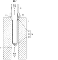
- FIG. 2 is a cross-sectional view showing the configuration of the filter 30 included in the polycrystalline silicon S1 manufacturing apparatus 1 shown in FIG.
- the filter 30 has a cylindrical shape and includes a first end 31, a second end 32, and a filter surface 33.
- the filter 30 has a shape in which the first end 31 is opened, the second end 32 on the side opposite to the first end 31 is closed, and the filter surface 33 extends between the first end 31 and the second end 32. Is.
- the filter 30 is preferably made of a material having high corrosion resistance to the raw material gas G1, for example, stainless steel containing 10% or more of Ni, corrosion resistant materials (Hastelloy, Inconel 600, Inconel 800, Incoloy 800H, etc.) and the like. It can be composed of ceramics (alumina, titania, zirconia, quartz, silicon carbide, silicon nitride, aluminum nitride, etc.). Considering economic efficiency, the filter 30 is preferably made of stainless steel containing 10% or more of Ni, and more preferably made of SUS316L.
- the first end 31 is arranged on the downstream side of the supply flow path, and the second end 32 is arranged on the upstream side of the supply flow path.
- the structure of the filter 30 is such that the first end 31 is arranged on the side opposite to the second end 32.
- the first end 31 of the filter 30 is fixed to the connecting member CN1 attached to the inflow port 111.
- a filter 30 is fixed to one end of the connecting member CN1, and a supply nozzle 40 is attached to the other end of the connecting member CN1. Further, by removing the connecting member CN1 from the inflow port 111, the filter 30 fixed to the connecting member CN1 can be easily cleaned.
- the outer peripheral side of the first end 31 is fixed to the inner wall of the supply flow path so that the first end 31 and the second end 32 are lined up along the inner wall of the supply flow path. That is, the outer peripheral side of the first end 31 is fixed to at least one inner wall of the supply pipe 20, the through hole H1 of the bottom portion 11, and the supply nozzle 40.
- the surface area of the filter 30 can be increased, the pressure loss of the raw material gas G1 due to the installation of the filter 30 can be reduced. Further, the raw material gas G1 can be stably supplied without clogging the filter 30 until the deposition of the polycrystalline silicon S1 is completed. Therefore, polycrystalline silicon S1 can be efficiently produced.
- the filter surface 33 may be made of, for example, a mesh or a sintered body of fine powder such as metal or ceramic. Further, the filter surface 33 may be composed of a structure in which a mesh and a sintered body are overlapped. In this case, it is preferable that the mesh is arranged on the outside and the sintered body is arranged on the inside.
- impurities mixed in the raw material gas G1 for silicon precipitation can be removed by the filter 30, and the raw material gas G1 from which the impurities have been removed can be supplied into the reactor 10.
- Polycrystalline silicon S1 can be produced. Therefore, the impurity concentration of the produced polycrystalline silicon S1 can be reduced.
- the filter 30 removes impurities mixed in the raw material gas G1 (impurity removing step).
- the impurity removing step is preferably performed immediately before the raw material gas G1 is supplied into the reactor 10. As a result, the amount of impurities that enter the reactor 10 can be reduced as much as possible.
- polycrystalline silicon S1 is precipitated by supplying the raw material gas G1 from which impurities have been removed in the impurity removing step into the reactor 10 (silicon precipitation step). Further, in the method for producing polycrystalline silicon S1, the raw material gas G1 is preferably a mixed gas of chlorosilanes and hydrogen.
- the raw material gas G1 contains chlorosilanes having chlorine in the molecule and also having corrosiveness, the material of the supply pipe 20 is eroded, and rust and chloride are generated on the surface, resulting in rust. Even if a part of chloride or chloride is mixed in the raw material gas G1, it can be prevented from entering the reactor 10.
- the chlorosilanes are, for example, tetrachlorosilane, trichlorosilane, dichlorosilane, monochlorosilane, and the like, and in general, trichlorosilane is preferably used as the chlorosilanes.
- the polycrystalline silicon S1 produced by the above-mentioned method for producing polycrystalline silicon S1 is also included in the technical scope of the present invention.
- FIG. 3 is a diagram showing an example of the configuration of the filter 30A included in the polycrystalline silicon S1 manufacturing apparatus according to the second embodiment of the present invention.
- the view shown by FA is a front view of the filter 30A
- the view shown by FB is a side view of the filter 30A.
- the manufacturing apparatus according to the second embodiment is different from the manufacturing apparatus 1 according to the first embodiment in that the filter 30 is changed to the filter 30A.
- a part of the filter 30A has a tapered shape that tapers from the first end 31A connected to the connecting member CN1 toward the second end 32A opposite to the first end 31A. .. That is, a part of the filter 30A has a tapered shape that tapers from the inflow port 111 toward the upstream of the supply flow path.
- the filter 30A may have a tapered shape that tapers from the inflow port 111 toward the upstream of the supply flow path.
- the manufacturing apparatus according to the second embodiment may include, instead of the filter 30A, a filter having a tapered shape in which at least a part thereof tapers from the upstream of the supply flow path toward the inflow port 111.
- the filter 30A even if the raw material gas G1 collides with the filter 30A, the flow of the raw material gas G1 is reduced from being obstructed by the filter 30A, and the pressure loss of the raw material gas G1 due to the installation of the filter 30A is reduced. be able to.
- the filter having a tapered shape in which at least a part of the filter tapers from the upstream of the supply flow path toward the inflow port 111 Even in this case, since the space through which the raw material gas G1 passes becomes wider toward the inflow port 111 from the upstream of the supply flow path, the raw material gas G1 can be smoothly passed. Therefore, the pressure loss of the raw material gas G1 due to the installation of the filter can be reduced.
- a cutout surface 35 is formed in the filter 30A by cutting out a part of the surface 34 of the filter 30A.
- a plate-shaped filter 36 is attached to the cutout surface 35 to form the plate-shaped filter 36 as a filter surface.
- the cutout surface 35 and the plate-shaped filter 36 may extend between the first end 31A and the second end 32A.
- the cutout surface 35 and the plate-shaped filter 36 have a shape in which the width increases in the direction orthogonal to the stretching direction of the filter 30A from the first end 31A to the second end 32A. Further, as shown in FIG. 3, the cutout surface 35 and the plate-shaped filter 36 are formed at two positions symmetrically with respect to the center line L1 of the filter 30A along the stretching direction of the filter 30A, respectively.
- the plate-shaped filter 36 can be attached, for example, by welding or welding, and specifically, by fusion welding, pressure welding, or brazing.
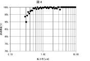
- FIG. 4 is a diagram showing the filtration accuracy of the filter 30A shown in FIG.
- the size of impurities mixed in the raw material gas G1 supplied into the reactor 10 is about 1 ⁇ m or more. Therefore, the filtration accuracy of the filter 30A is preferably 95% or more with respect to the particles having a particle size of 1 ⁇ m or more. That is, the filter 30A preferably removes 95% of the particles having a particle size of 1 ⁇ m or more.
- the filtration accuracy of the filter 30A is 90% or more with respect to the particles having a particle size of 0.3 ⁇ m or more.
- the filter 30A preferably removes 90% or more of the particles having a particle size of 0.3 ⁇ m or more. According to the above configuration, impurities mixed in the raw material gas G1 can be removed with high efficiency.
- filtration accuracy means the filtration accuracy measured by the following method.
- AC dust an air cleaner test dust (hereinafter referred to as AC dust) is supplied to the upstream side of the filter 30A by using a dry dispersion type aerosol generator (RBG1000, manufactured by PALAS).
- the syringe diameter of the syringe for supplying the compressed powder is set to 7 mm, and the supply speed is set to 5 mm / h.
- the supply speed corresponds to a supply speed of 190 mg / h assuming that the bulk specific gravity of the compressed powder is 1 g / cc.
- diluted air is supplied to the upstream side of the filter 30A at a flow rate of 40 L / min.
- the particle size distribution upstream of the filter 30A is measured for 20 seconds, and then the particle size distribution downstream of the filter 30A is measured for 20 seconds.
- the filtration accuracy at the particle size is obtained by dividing the average number of particles downstream of the filter 30A [number of particles / cm 3 ] by the average number of particles upstream of the filter 30A [number of particles / cm 3]. Is calculated.
- the measurement of the particle size distribution upstream of the filter 30A and the measurement of the particle size distribution downstream of the filter 30A are repeated three times, and the average value of the filtration accuracy calculated by each of these three measurements is used as the final filtration of the filter 30A. Accuracy. As a result of measuring the filtration accuracy of the filter 30A in this way, the filtration accuracy shown in FIG. 4 was obtained.
- the horizontal axis is the particle size [ ⁇ m]
- the vertical axis is the filtration accuracy [%].
- a filter 30A is used as the filter, and a plate-shaped filter 36 composed of a sintered body is used. Further, in the measurement result, a filter 30A made of SUS316L is used, and the dimensions of the filter 30A are as shown below.
- the length M1 along the stretching direction of the filter 30A at the opening of the filter 30A is 300 mm, and the length along the stretching direction of the filter 30A at the tip T1 of the filter 30A.
- M2 is 50 mm.
- the thickness of the plate filter 36 is 1 mm.
- the filter 30A is manufactured by cutting out a part of a pipe, the outer diameter of the pipe is 27.2 mm, and the inner diameter of the pipe is 23.9 mm.
- FIG. 5 is a diagram showing an example of the configuration of a filter included in the polycrystalline silicon S1 manufacturing apparatus according to the third embodiment of the present invention.
- the view shown by FC is a front view of the filter 30B
- the view shown by FD is a perspective view of the filter 30C.
- the manufacturing apparatus according to the third embodiment is different from the manufacturing apparatus 1 according to the first embodiment in that the filter 30 is changed to the filter 30B or the filter 30C.
- the filter 30B is composed of a cylindrical portion 41, a central portion 42, and a conical portion 43. From the downstream side of the supply flow path, the cylindrical portion 41, the central portion 42, and the conical portion 43 are formed in this order.
- the cylindrical portion 41 has a cylindrical shape and is connected to the connecting member CN1.
- the central portion 42 has a shape in which the apex is cut from the cone.
- the conical portion 43 has a conical shape.
- the central portion 42 and the conical portion 43 are formed so that the inclination angle of the central portion 42 is smaller than the inclination angle of the conical portion 43.
- a part of the filter 30B may have the tapered shape due to the central portion 42 and the conical portion 43. Due to the configuration of the filter 30B, the flow of the raw material gas G1 is less likely to be obstructed by the filter 30B.
- the entire filter included in the manufacturing apparatus according to the third embodiment may have a conical shape.
- the filter 30C has the shape of a triangular prism.
- the quadrangular surface 44 having the smallest area among the three quadrangular surfaces related to the triangular prism of the filter 30C is connected to the connecting member CN1.
- the filter 30C may have a shape in which the surface 44 is changed to a polygon other than a quadrangle.
- the filter 30C may have the tapered shape due to the triangular prism.
- the filter included in the manufacturing apparatus according to the third embodiment may have a polygonal pyramid shape such as a triangular pyramid or a quadrangular pyramid. In this case, the bottom of the polygonal pyramid is connected to the connecting member CN1, and the top is arranged on the upstream side of the supply flow path.
- FIG. 6 is a diagram showing an example of the configuration of a filter included in the polycrystalline silicon S1 manufacturing apparatus according to the fourth embodiment of the present invention.
- the view shown by FE is a front view of the filter 30D
- the view shown by FF is a side view of the filter 30D.
- the manufacturing apparatus according to the fourth embodiment is different from the manufacturing apparatus 1 according to the first embodiment in that the filter 30 is changed to the filter 30D.
- the filter 30D has a disk shape.
- An opening 48 is formed in the center of the flat surface 47 on the front side of the filter 30D, and a plate-shaped filter 49 is attached to the opening 48 so as to close the opening 48.
- the filter 30D has a side surface 51.
- the side surface 51 is connected to the connecting member CN1.
- the filter 30D is preferably stretched in a direction orthogonal to the flow direction of the raw material gas G1 flowing through the supply flow path.
- the shape of the filter 30D is not limited to the disk shape, and for example, the plane orthogonal to the flow direction of the raw material gas G1 may be a quadrangle or a triangle other than a circle. Further, the filter 30D may be extended in a direction inclined from a direction orthogonal to the flow direction of the raw material gas G1 flowing through the supply flow path.
- the apparatus for producing polycrystalline silicon is a supply flow path including a reactor accommodating a raw material gas for silicon precipitation and an inflow port formed in the reactor as the raw material gas flows in. It is provided with a pipe for forming the supply flow path for supplying the raw material gas into the reactor, and a filter provided in the supply flow path and for removing impurities mixed in the raw material gas. ..
- impurities mixed in the raw material gas for silicon precipitation can be removed by a filter, so that the polycrystalline silicon can be produced by supplying the raw material gas from which the impurities have been removed into the reactor. Therefore, the impurity concentration of the produced polycrystalline silicon can be reduced.
- the filter may be provided at the inflow port in the supply flow path. According to the above configuration, the amount of impurities entering the reactor can be reduced as much as possible by providing the filter at the inflow port.
- the raw material gas may be a mixed gas of chlorosilanes and hydrogen. According to the above configuration, although the raw material gas contains chlorosilanes having chlorine in the molecule and also having corrosiveness, the piping material is eroded and rust and chloride are generated on the surface, resulting in rust and rust. Even if a part of chloride is mixed with the raw material gas, it can be prevented from entering the reactor.
- the piping forming the supply flow path may be made of stainless steel. According to the above configuration, due to the constituent elements of stainless steel, for example, heavy metal elements Fe (iron), Ni (nickel), Cr (chromium), Mn (manganese), Cu (copper), Ti (titanium). ), Mo (molybdenum) and Nb (niobium) can be prevented from entering the reactor.
- the filtration accuracy of the filter may be 90% or more with respect to particles having a particle size of 0.3 ⁇ m or more. According to the above configuration, impurities mixed in the raw material gas can be removed with high efficiency.
- At least a part of the filter may have a tapered shape that tapers from the inflow port toward the upstream of the supply flow path, or a tapered shape that tapers from the upstream of the supply flow path toward the inflow port. ..
- the filter has a shape in which the first end is open, the second end opposite to the first end is closed, and the filter surface extends between the first end and the second end.
- the outer peripheral side of the first end may be fixed to the inner wall of the supply flow path so that the first end and the second end are lined up along the inner wall of the supply flow path.
- the surface area of the filter can be increased, so that the pressure loss of the raw material gas due to the installation of the filter can be reduced.
- the raw material gas can be stably supplied without blocking the filter until the completion of the precipitation of polycrystalline silicon. Therefore, polycrystalline silicon can be efficiently produced.
- the method for producing polycrystalline silicon according to one aspect of the present invention is mixed with the raw material gas by a filter provided in a supply flow path for supplying the raw material gas into a reactor containing the raw material gas for silicon precipitation. It includes an impurity removing step of removing the impurities, and a silicon precipitation step of precipitating polycrystalline silicon by supplying the raw material gas from which the impurities have been removed in the impurity removing step into the reactor.
- the impurity removing step may be performed immediately before the raw material gas is supplied into the reactor. According to the above configuration, the amount of impurities entering the reactor can be reduced as much as possible by performing the impurity removing step immediately before the raw material gas is supplied into the reactor.
- the polycrystalline silicon according to one aspect of the present invention may be produced by the method for producing polycrystalline silicon.
- a polycrystalline silicon rod was manufactured using the polycrystalline silicon S1 manufacturing apparatus having the structure of the second embodiment of the present invention. That is, in the manufacturing apparatus 1 shown in FIG. 1, a polycrystalline silicon rod was manufactured by using a filter 30 replaced with a filter 10A.
- the reactor 10 is capable of erecting 10 polycrystalline silicon rods (5 pairs of inverted U-shaped polycrystalline silicon S1), and a polycrystalline silicon S1 manufacturing apparatus is used. The production of the crystalline silicon rod was carried out as described below.
- Each silicon core wire having an inverted U shape having a height of 2000 mm installed at the bottom 11 of the reactor 10 was energized, and each silicon core wire was heated so that the temperature of each silicon core wire became about 1000 ° C.
- a fully purified mixed gas of trichlorosilane and hydrogen is supplied into the reactor 10 by flowing through the supply pipe 20, and each of the silicon core wires (one side of the square cross section is 8 mm).
- Polycrystalline silicon was precipitated in the water. Precipitation of polycrystalline silicon continued until the diameter of the polycrystalline silicon rod grew to 120 mm.
- the supply pipe 20 is made of stainless steel, and the manufacture of the polycrystalline silicon rod under the same conditions is repeated 100 times before the implementation of this embodiment. It was.
- the filter the filter 30A shown in FIG. 3 made of SUS316L was used. The filtration accuracy of the filter 30A was such that 90% or more of the particles having a particle size of 0.3 ⁇ m or more could be removed.
- the mounting position of the filter 30A with respect to the supply pipe 20 was the mounting position shown in FIG.
- a cylinder having a diameter of 10 mm and a length of 120 mm was hollowed out from the polycrystalline silicon rod in the horizontal direction orthogonal to the longitudinal direction in the vicinity of a position in the middle of the polycrystalline silicon rod in the longitudinal direction.
- the columnar body extends in the horizontal direction.
- a polycrystalline silicon cylinder obtained by hollowing out the polycrystalline silicon rod.
- the radial direction is assumed to be the radial direction of the cross section of the polycrystalline silicon rod.
- a cylinder having a diameter of 10 mm and a height of 4 mm is obtained by vertically cutting the cylinder at a position 2 mm in the front-rear direction in the radial direction from a position 4 mm inside in the radial direction from one end of the cylinder (the outer skin surface of the polycrystalline silicon rod).
- a sample for measuring the shape of the outer skin was obtained.
- the cylinder is vertically arranged at a position 2 mm in the front-rear direction in the radial direction. It was cut to obtain a measurement sample in the middle part. Further, in the cylinder, the cylinder is vertically cut at the center position of the cross section of the polycrystalline silicon rod and the position outside the center position by 4 mm in the radial direction to obtain a sample for measuring the core wire portion. It was.
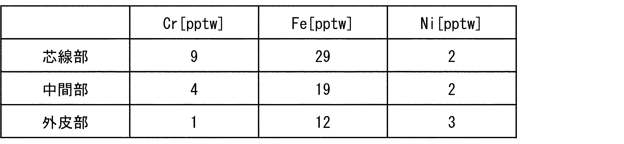
- the metal content of each of these measurement samples was analyzed. Specifically, the amount of each metal element of Cr, Fe, and Ni in the solution obtained by dissolving the target measurement sample in a fluorine mixed solution is analyzed by inductively coupled plasma mass spectrometry (ICP-MS). did. The average value of the analytical values of 10 polycrystalline silicon rods for each measurement sample was determined as the metal concentration in the site of each polycrystalline silicon rod. As a result of this example, the metal concentration in each part is shown in Table 1 below.
- the polycrystalline silicon rod was manufactured in the same manner as in the above embodiment except that the filter 30A was not provided in the supply pipe 20.
- the state of contamination by metal impurities was confirmed by the same method as in the above-mentioned example.
- the metal concentration in each site is shown in Table 2 below.
- the polycrystalline silicon rod of the above-mentioned example has Cr in all of the core wire portion, the intermediate portion and the outer skin portion as compared with the polycrystalline silicon rod of the present comparative example. , Fe, and Ni metal concentrations were significantly reduced. From this result, it was possible to confirm the significant effect of suppressing the contamination of metal impurities by providing the filter 30A in the supply pipe 20.
- the present invention can be used for producing polycrystalline silicon.
Landscapes
- Chemical & Material Sciences (AREA)
- Organic Chemistry (AREA)
- Inorganic Chemistry (AREA)
- Chemical Kinetics & Catalysis (AREA)
- General Chemical & Material Sciences (AREA)
- Engineering & Computer Science (AREA)
- Materials Engineering (AREA)
- Mechanical Engineering (AREA)
- Metallurgy (AREA)
- Physics & Mathematics (AREA)
- Geometry (AREA)
- Silicon Compounds (AREA)
Abstract
Description
<多結晶シリコンS1の製造装置1の構成>
図1は、本発明の実施形態1に係る多結晶シリコンS1の製造装置1を示す概略図である。図1に示すように、多結晶シリコンS1の製造装置1は、反応器10と、供給配管20(配管)と、フィルタ30と、供給ノズル40と、電極50と、排出配管60と、を備える。なお、製造装置1は、供給ノズル40を備えていなくてもよい。
フィルタ30は、前記供給流路に設けられるとともに、原料ガスG1に混入した不純物を除去する部材である。つまり、フィルタ30は、供給配管20、流入口111、供給ノズル40および流入口E1のいずれかに設けられる。反応器10内に侵入する不純物の量を極力低減するために、フィルタ30は、前記供給流路における反応器10の近傍または反応器10の内部に設けられることが好ましく、例えば、前記供給流路における流入口111に設けられることが好ましい。
次に、多結晶シリコンS1の製造方法の一例について説明する。まず、フィルタ30によって、原料ガスG1に混入した不純物を除去する(不純物除去工程)。前記不純物除去工程は、原料ガスG1が反応器10内に供給される直前に行われることが好ましい。これにより、反応器10内に侵入する不純物の量を極力低減することができる。
本発明の実施形態2について、以下に説明する。なお、説明の便宜上、実施形態1にて説明した部材と同じ機能を有する部材については、同じ符号を付記し、その説明を繰り返さない。図3は、本発明の実施形態2に係る多結晶シリコンS1の製造装置が備えるフィルタ30Aの構成の一例を示す図である。図3において、FAで示す図は、フィルタ30Aの正面図であり、FBで示す図は、フィルタ30Aの側面図である。
図4は、図3に示すフィルタ30Aの濾過精度を示す図である。本発明者が走査電子顕微鏡(Scanning Electron Microscope)を用いて不純物を観察した結果によると、反応器10内に供給される原料ガスG1に混入する不純物の大きさは、約1μm以上である。したがって、フィルタ30Aの濾過精度は、粒子径が1μm以上である粒子に対して95%以上であることが好ましい。つまり、フィルタ30Aは、粒子径が1μm以上である粒子のうち95%の粒子を除去することが好ましい。
本発明の実施形態3について、以下に説明する。なお、説明の便宜上、実施形態1および2にて説明した部材と同じ機能を有する部材については、同じ符号を付記し、その説明を繰り返さない。図5は、本発明の実施形態3に係る多結晶シリコンS1の製造装置が備えるフィルタの構成の一例を示す図である。図5において、FCで示す図は、フィルタ30Bの正面図であり、FDで示す図は、フィルタ30Cの斜視図である。
本発明の実施形態4について、以下に説明する。なお、説明の便宜上、実施形態1から3にて説明した部材と同じ機能を有する部材については、同じ符号を付記し、その説明を繰り返さない。図6は、本発明の実施形態4に係る多結晶シリコンS1の製造装置が備えるフィルタの構成の一例を示す図である。図6において、FEで示す図は、フィルタ30Dの正面図であり、FFで示す図は、フィルタ30Dの側面図である。
本発明の一態様に係る多結晶シリコンの製造装置は、シリコン析出用の原料ガスを収容する反応器と、前記原料ガスが流入するとともに前記反応器に形成される流入口を含む供給流路であって、前記原料ガスを前記反応器内に供給するための前記供給流路を形成する配管と、前記供給流路に設けられるとともに、前記原料ガスに混入した不純物を除去するフィルタと、を備える。

10 反応器
20 供給配管(配管)
30、30A、30B、30C、30D フィルタ
31、31A 第1端
32、32A 第2端
33 フィルタ面
111、E1 流入口
G1 原料ガス
S1 多結晶シリコン
Claims (10)
- シリコン析出用の原料ガスを収容する反応器と、
前記原料ガスが流入するとともに前記反応器に形成される流入口を含む供給流路であって、前記原料ガスを前記反応器内に供給するための前記供給流路を形成する配管と、
前記供給流路に設けられるとともに、前記原料ガスに混入した不純物を除去するフィルタと、を備えることを特徴とする多結晶シリコンの製造装置。 - 前記フィルタは、前記供給流路における前記流入口に設けられることを特徴とする請求項1に記載の多結晶シリコンの製造装置。
- 前記原料ガスは、クロロシラン類と水素との混合ガスであることを特徴とする請求項1または2に記載の多結晶シリコンの製造装置。
- 前記供給流路を形成する配管は、ステンレス鋼製であることを特徴とする請求項1から3のいずれか1項に記載の多結晶シリコンの製造装置。
- 前記フィルタの濾過精度は、粒子径が0.3μm以上である粒子に対して90%以上であることを特徴とする請求項1から4のいずれか1項に記載の多結晶シリコンの製造装置。
- 前記フィルタの少なくとも一部は、前記流入口から前記供給流路の上流に向かうにつれて先細りするテーパ形状、または、前記供給流路の上流から前記流入口に向かうにつれて先細りするテーパ形状であることを特徴とする請求項1から5のいずれか1項に記載の多結晶シリコンの製造装置。
- 前記フィルタは、第1端が開放し、前記第1端とは反対側の第2端が閉塞するとともに、前記第1端と前記第2端との間をフィルタ面が延伸する形状であり、
前記第1端および前記第2端が前記供給流路の内壁に沿って並ぶように、前記第1端の外周側が前記供給流路の内壁に固定されることを特徴とする請求項1から6のいずれか1項に記載の多結晶シリコンの製造装置。 - シリコン析出用の原料ガスを収容する反応器内に前記原料ガスを供給するための供給流路に設けられるフィルタによって、前記原料ガスに混入した不純物を除去する不純物除去工程と、
前記不純物除去工程で前記不純物が除去された前記原料ガスを前記反応器内に供給することにより、多結晶シリコンを析出させるシリコン析出工程と、を含むことを特徴とする多結晶シリコンの製造方法。 - 前記不純物除去工程は、前記原料ガスが前記反応器内に供給される直前に行われることを特徴とする請求項8に記載の多結晶シリコンの製造方法。
- 請求項8または9に記載の多結晶シリコンの製造方法によって製造されることを特徴とする多結晶シリコン。
Priority Applications (5)
| Application Number | Priority Date | Filing Date | Title |
|---|---|---|---|
| CN202080069173.2A CN114502509B (zh) | 2019-10-02 | 2020-09-24 | 多晶硅的制造装置、制造方法及多晶硅 |
| JP2021551166A JP7098068B2 (ja) | 2019-10-02 | 2020-09-24 | 多結晶シリコンの製造装置および製造方法 |
| US17/765,021 US20230002237A1 (en) | 2019-10-02 | 2020-09-24 | Apparatus and method for producing polycrystalline silicon, and polycrystalline silicon |
| EP20872147.2A EP4039644A4 (en) | 2019-10-02 | 2020-09-24 | Apparatus and method for producing polycrystalline silicon, and polycrystalline silicon |
| KR1020227010615A KR20220073750A (ko) | 2019-10-02 | 2020-09-24 | 다결정 실리콘의 제조 장치, 제조 방법 및 다결정 실리콘 |
Applications Claiming Priority (2)
| Application Number | Priority Date | Filing Date | Title |
|---|---|---|---|
| JP2019-182377 | 2019-10-02 | ||
| JP2019182377 | 2019-10-02 |
Publications (1)
| Publication Number | Publication Date |
|---|---|
| WO2021065685A1 true WO2021065685A1 (ja) | 2021-04-08 |
Family
ID=75337307
Family Applications (1)
| Application Number | Title | Priority Date | Filing Date |
|---|---|---|---|
| PCT/JP2020/036104 Ceased WO2021065685A1 (ja) | 2019-10-02 | 2020-09-24 | 多結晶シリコンの製造装置、製造方法および多結晶シリコン |
Country Status (7)
| Country | Link |
|---|---|
| US (1) | US20230002237A1 (ja) |
| EP (1) | EP4039644A4 (ja) |
| JP (1) | JP7098068B2 (ja) |
| KR (1) | KR20220073750A (ja) |
| CN (1) | CN114502509B (ja) |
| TW (1) | TWI844737B (ja) |
| WO (1) | WO2021065685A1 (ja) |
Cited By (3)
| Publication number | Priority date | Publication date | Assignee | Title |
|---|---|---|---|---|
| WO2023140184A1 (ja) | 2022-01-18 | 2023-07-27 | 株式会社トクヤマ | 多結晶シリコンロッド製造用反応炉、ガス供給ノズル、多結晶シリコンロッドの製造方法および多結晶シリコンロッド |
| JP7854026B1 (ja) | 2024-11-06 | 2026-04-30 | 株式会社トクヤマ | フィルタの洗浄方法及びフィルタの洗浄装置 |
| JP7854025B1 (ja) | 2024-11-06 | 2026-04-30 | 株式会社トクヤマ | フィルタの洗浄装置 |
Citations (7)
| Publication number | Priority date | Publication date | Assignee | Title |
|---|---|---|---|---|
| JPS60254614A (ja) * | 1984-05-14 | 1985-12-16 | アライド・コーポレーシヨン | 光誘導による導電性ケイ化チタンフイルムの化学蒸着法 |
| JPH06310444A (ja) * | 1993-04-27 | 1994-11-04 | Ryoden Semiconductor Syst Eng Kk | 液体原料用cvd装置 |
| JPH1120895A (ja) * | 1997-05-07 | 1999-01-26 | Tokuyama Corp | トリクロロシランおよび四塩化珪素の貯蔵方法 |
| JP2004002122A (ja) * | 2002-06-03 | 2004-01-08 | Denki Kagaku Kogyo Kk | 窒化ケイ素粉末の製造方法 |
| JP2005008430A (ja) * | 2003-06-16 | 2005-01-13 | Tokuyama Corp | シリコンの製造方法 |
| JP2013212974A (ja) * | 2012-03-05 | 2013-10-17 | Tokuyama Corp | 多結晶シリコンの製造方法及び該製造方法に還元剤として用いる水素ガスの製造方法 |
| JP2018530511A (ja) | 2015-10-14 | 2018-10-18 | ワッカー ケミー アクチエンゲゼルシャフトWacker Chemie AG | 多結晶シリコンを堆積させるための反応器 |
Family Cites Families (16)
| Publication number | Priority date | Publication date | Assignee | Title |
|---|---|---|---|---|
| US3091517A (en) * | 1959-11-25 | 1963-05-28 | Texas Instruments Inc | Method for recovery and recycling hydrogen and silicon halides from silicon deposition reactor exhaust |
| FR1417109A (fr) * | 1962-05-24 | 1965-11-12 | Siemens Ag | Dispositif pour l'obtention d'un matériau semi-conducteur extrêment pur |
| KR100294057B1 (ko) * | 1995-08-22 | 2001-09-17 | 모리시타 요이찌 | 실리콘 구조체층을 포함하는 반도체 장치, 그 층의 제조방법 및 제조장치와 그 층을 이용한 태양전지 |
| JP5217162B2 (ja) * | 2005-12-27 | 2013-06-19 | 住友化学株式会社 | 多結晶シリコンの製造方法 |
| JP5308288B2 (ja) * | 2009-09-14 | 2013-10-09 | 信越化学工業株式会社 | 多結晶シリコン製造用反応炉、多結晶シリコン製造システム、および多結晶シリコンの製造方法 |
| US8657958B2 (en) * | 2010-09-02 | 2014-02-25 | Savi Research, Inc. | CVD-Siemens monosilane reactor process with complete utilization of feed gases and total recycle |
| CN202921106U (zh) * | 2012-08-10 | 2013-05-08 | 中国恩菲工程技术有限公司 | 一种用于多晶硅生产工艺的气体过滤装置 |
| CN102814084A (zh) * | 2012-08-10 | 2012-12-12 | 中国恩菲工程技术有限公司 | 一种用于多晶硅生产工艺的气体过滤装置 |
| KR101311739B1 (ko) * | 2013-01-14 | 2013-10-14 | 주식회사 아이제이피에스 | 폴리실리콘 제조장치 |
| DE102013206236A1 (de) * | 2013-04-09 | 2014-10-09 | Wacker Chemie Ag | Gasverteiler für Siemens-Reaktor |
| JP2015173154A (ja) * | 2014-03-11 | 2015-10-01 | 東京エレクトロン株式会社 | 縦型熱処理装置、縦型熱処理装置の運転方法及び記憶媒体 |
| US9440262B2 (en) * | 2014-11-07 | 2016-09-13 | Rec Silicon Inc | Apparatus and method for silicon powder management |
| CN105609406B (zh) * | 2014-11-19 | 2018-09-28 | 株式会社日立国际电气 | 半导体器件的制造方法、衬底处理装置、气体供给系统 |
| KR101895538B1 (ko) * | 2015-09-08 | 2018-09-05 | 한화케미칼 주식회사 | 폴리실리콘 제조 장치 |
| EP3153221A1 (en) * | 2015-10-09 | 2017-04-12 | Total Marketing Services | Siox filtration unit and method for operating the siox filtration unit |
| WO2018230380A1 (ja) * | 2017-06-16 | 2018-12-20 | 株式会社トクヤマ | ポリシリコンの製造方法 |
-
2020
- 2020-09-24 WO PCT/JP2020/036104 patent/WO2021065685A1/ja not_active Ceased
- 2020-09-24 JP JP2021551166A patent/JP7098068B2/ja active Active
- 2020-09-24 US US17/765,021 patent/US20230002237A1/en active Pending
- 2020-09-24 EP EP20872147.2A patent/EP4039644A4/en active Pending
- 2020-09-24 KR KR1020227010615A patent/KR20220073750A/ko active Pending
- 2020-09-24 CN CN202080069173.2A patent/CN114502509B/zh active Active
- 2020-09-28 TW TW109133592A patent/TWI844737B/zh active
Patent Citations (7)
| Publication number | Priority date | Publication date | Assignee | Title |
|---|---|---|---|---|
| JPS60254614A (ja) * | 1984-05-14 | 1985-12-16 | アライド・コーポレーシヨン | 光誘導による導電性ケイ化チタンフイルムの化学蒸着法 |
| JPH06310444A (ja) * | 1993-04-27 | 1994-11-04 | Ryoden Semiconductor Syst Eng Kk | 液体原料用cvd装置 |
| JPH1120895A (ja) * | 1997-05-07 | 1999-01-26 | Tokuyama Corp | トリクロロシランおよび四塩化珪素の貯蔵方法 |
| JP2004002122A (ja) * | 2002-06-03 | 2004-01-08 | Denki Kagaku Kogyo Kk | 窒化ケイ素粉末の製造方法 |
| JP2005008430A (ja) * | 2003-06-16 | 2005-01-13 | Tokuyama Corp | シリコンの製造方法 |
| JP2013212974A (ja) * | 2012-03-05 | 2013-10-17 | Tokuyama Corp | 多結晶シリコンの製造方法及び該製造方法に還元剤として用いる水素ガスの製造方法 |
| JP2018530511A (ja) | 2015-10-14 | 2018-10-18 | ワッカー ケミー アクチエンゲゼルシャフトWacker Chemie AG | 多結晶シリコンを堆積させるための反応器 |
Non-Patent Citations (1)
| Title |
|---|
| See also references of EP4039644A4 |
Cited By (6)
| Publication number | Priority date | Publication date | Assignee | Title |
|---|---|---|---|---|
| WO2023140184A1 (ja) | 2022-01-18 | 2023-07-27 | 株式会社トクヤマ | 多結晶シリコンロッド製造用反応炉、ガス供給ノズル、多結晶シリコンロッドの製造方法および多結晶シリコンロッド |
| JP7395793B1 (ja) * | 2022-01-18 | 2023-12-11 | 株式会社トクヤマ | 多結晶シリコンロッド製造用反応炉、ガス供給ノズル、多結晶シリコンロッドの製造方法および多結晶シリコンロッド |
| CN118541331A (zh) * | 2022-01-18 | 2024-08-23 | 株式会社德山 | 多晶硅棒制造用反应炉、气体供给喷嘴、多晶硅棒的制造方法以及多晶硅棒 |
| EP4434939A4 (en) * | 2022-01-18 | 2025-12-03 | Tokuyama Corp | REACTION FURNITURE FOR PRODUCING A POLYCRYSTALLINE SILICON ROD, GAS FEED NOZZLE, PROCESS FOR PRODUCING A POLYCRYSTALLINE SILICON ROD AND POLYCRYSTALLINE SILICON ROD |
| JP7854026B1 (ja) | 2024-11-06 | 2026-04-30 | 株式会社トクヤマ | フィルタの洗浄方法及びフィルタの洗浄装置 |
| JP7854025B1 (ja) | 2024-11-06 | 2026-04-30 | 株式会社トクヤマ | フィルタの洗浄装置 |
Also Published As
| Publication number | Publication date |
|---|---|
| CN114502509A (zh) | 2022-05-13 |
| EP4039644A4 (en) | 2024-02-14 |
| CN114502509B (zh) | 2025-08-05 |
| KR20220073750A (ko) | 2022-06-03 |
| EP4039644A1 (en) | 2022-08-10 |
| TW202135256A (zh) | 2021-09-16 |
| US20230002237A1 (en) | 2023-01-05 |
| JP7098068B2 (ja) | 2022-07-08 |
| JPWO2021065685A1 (ja) | 2021-04-08 |
| TWI844737B (zh) | 2024-06-11 |
Similar Documents
| Publication | Publication Date | Title |
|---|---|---|
| JP7098068B2 (ja) | 多結晶シリコンの製造装置および製造方法 | |
| TW200527491A (en) | Exhaust conditioning system for semiconductor reactor | |
| JP7282691B2 (ja) | 微粒子の製造方法 | |
| JP6763428B2 (ja) | 多結晶シリコンロッド及びその製造方法 | |
| CN103945942B (zh) | 用于流化床反应器的探头组件 | |
| JP2023502383A (ja) | ナノワイヤネットワーク | |
| JP2018176026A (ja) | 微粒子製造装置及び微粒子製造方法 | |
| JP7395793B1 (ja) | 多結晶シリコンロッド製造用反応炉、ガス供給ノズル、多結晶シリコンロッドの製造方法および多結晶シリコンロッド | |
| JP2014080352A (ja) | 多結晶シリコンの堆積のための方法 | |
| JP6328565B2 (ja) | 多結晶シリコンロッドおよびその製造方法 | |
| JP6619093B2 (ja) | 多結晶シリコンを堆積させるための反応器 | |
| RU2686150C1 (ru) | Установка плазмохимического синтеза наноразмерных порошков и используемый в ней циклон | |
| EP1697040A1 (en) | Device and process for the deposition of ultrafine particles from the gas phase | |
| US20160201223A1 (en) | Polycrystalline silicon fragments and process for comminuting polycrystalline silicon rods | |
| JP6919408B2 (ja) | 反応容器 | |
| CN111108065A (zh) | 三氯硅烷制造装置以及三氯硅烷的制造方法 | |
| CN113789572A (zh) | 碳化硅单晶生长用坩埚结构和碳化硅单晶的生长方法 | |
| RU2311225C1 (ru) | Плазменная установка для получения нанодисперсных порошков | |
| KR20210026074A (ko) | 실리콘산화물 나노 파우더 포집장치 | |
| CN105189351A (zh) | 西门子反应器的气体分配器 | |
| JP4932718B2 (ja) | 金属粉末の製造方法 | |
| WO2021039569A1 (ja) | 多結晶シリコンロッドおよびその製造方法 | |
| JP7088774B2 (ja) | シリコン微粒子製造装置 | |
| CN216512891U (zh) | 多晶硅还原炉的硅芯结构、多晶硅还原炉 | |
| JP5335074B2 (ja) | 多結晶シリコンの製造方法及び多結晶シリコン製造用の反応炉 |
Legal Events
| Date | Code | Title | Description |
|---|---|---|---|
| 121 | Ep: the epo has been informed by wipo that ep was designated in this application |
Ref document number: 20872147 Country of ref document: EP Kind code of ref document: A1 |
|
| ENP | Entry into the national phase |
Ref document number: 2021551166 Country of ref document: JP Kind code of ref document: A |
|
| NENP | Non-entry into the national phase |
Ref country code: DE |
|
| ENP | Entry into the national phase |
Ref document number: 2020872147 Country of ref document: EP Effective date: 20220502 |
|
| WWG | Wipo information: grant in national office |
Ref document number: 202080069173.2 Country of ref document: CN |