WO2021066010A1 - 電池冷却器 - Google Patents
電池冷却器 Download PDFInfo
- Publication number
- WO2021066010A1 WO2021066010A1 PCT/JP2020/037148 JP2020037148W WO2021066010A1 WO 2021066010 A1 WO2021066010 A1 WO 2021066010A1 JP 2020037148 W JP2020037148 W JP 2020037148W WO 2021066010 A1 WO2021066010 A1 WO 2021066010A1
- Authority
- WO
- WIPO (PCT)
- Prior art keywords
- refrigerant
- filling chamber
- battery cooler
- refrigerant filling
- battery
- Prior art date
- Legal status (The legal status is an assumption and is not a legal conclusion. Google has not performed a legal analysis and makes no representation as to the accuracy of the status listed.)
- Ceased
Links
Images



Classifications
-
- H—ELECTRICITY
- H01—ELECTRIC ELEMENTS
- H01M—PROCESSES OR MEANS, e.g. BATTERIES, FOR THE DIRECT CONVERSION OF CHEMICAL ENERGY INTO ELECTRICAL ENERGY
- H01M10/00—Secondary cells; Manufacture thereof
- H01M10/60—Heating or cooling; Temperature control
- H01M10/65—Means for temperature control structurally associated with the cells
- H01M10/656—Means for temperature control structurally associated with the cells characterised by the type of heat-exchange fluid
- H01M10/6567—Liquids
- H01M10/6568—Liquids characterised by flow circuits, e.g. loops, located externally to the cells or cell casings
-
- F—MECHANICAL ENGINEERING; LIGHTING; HEATING; WEAPONS; BLASTING
- F28—HEAT EXCHANGE IN GENERAL
- F28D—HEAT-EXCHANGE APPARATUS, NOT PROVIDED FOR IN ANOTHER SUBCLASS, IN WHICH THE HEAT-EXCHANGE MEDIA DO NOT COME INTO DIRECT CONTACT
- F28D1/00—Heat-exchange apparatus having stationary conduit assemblies for one heat-exchange medium only, the media being in contact with different sides of the conduit wall, in which the other heat-exchange medium is a large body of fluid, e.g. domestic or motor car radiators
- F28D1/02—Heat-exchange apparatus having stationary conduit assemblies for one heat-exchange medium only, the media being in contact with different sides of the conduit wall, in which the other heat-exchange medium is a large body of fluid, e.g. domestic or motor car radiators with heat-exchange conduits immersed in the body of fluid
- F28D1/03—Heat-exchange apparatus having stationary conduit assemblies for one heat-exchange medium only, the media being in contact with different sides of the conduit wall, in which the other heat-exchange medium is a large body of fluid, e.g. domestic or motor car radiators with heat-exchange conduits immersed in the body of fluid with plate-like or laminated conduits
- F28D1/0308—Heat-exchange apparatus having stationary conduit assemblies for one heat-exchange medium only, the media being in contact with different sides of the conduit wall, in which the other heat-exchange medium is a large body of fluid, e.g. domestic or motor car radiators with heat-exchange conduits immersed in the body of fluid with plate-like or laminated conduits the conduits being formed by paired plates touching each other
- F28D1/0325—Heat-exchange apparatus having stationary conduit assemblies for one heat-exchange medium only, the media being in contact with different sides of the conduit wall, in which the other heat-exchange medium is a large body of fluid, e.g. domestic or motor car radiators with heat-exchange conduits immersed in the body of fluid with plate-like or laminated conduits the conduits being formed by paired plates touching each other the plates having lateral openings therein for circulation of the heat-exchange medium from one conduit to another
-
- B—PERFORMING OPERATIONS; TRANSPORTING
- B60—VEHICLES IN GENERAL
- B60L—PROPULSION OF ELECTRICALLY-PROPELLED VEHICLES; SUPPLYING ELECTRIC POWER FOR AUXILIARY EQUIPMENT OF ELECTRICALLY-PROPELLED VEHICLES; ELECTRODYNAMIC BRAKE SYSTEMS FOR VEHICLES IN GENERAL; MAGNETIC SUSPENSION OR LEVITATION FOR VEHICLES; MONITORING OPERATING VARIABLES OF ELECTRICALLY-PROPELLED VEHICLES; ELECTRIC SAFETY DEVICES FOR ELECTRICALLY-PROPELLED VEHICLES
- B60L50/00—Electric propulsion with power supplied within the vehicle
- B60L50/50—Electric propulsion with power supplied within the vehicle using propulsion power supplied by batteries or fuel cells
- B60L50/60—Electric propulsion with power supplied within the vehicle using propulsion power supplied by batteries or fuel cells using power supplied by batteries
- B60L50/64—Constructional details of batteries specially adapted for electric vehicles
-
- H—ELECTRICITY
- H01—ELECTRIC ELEMENTS
- H01M—PROCESSES OR MEANS, e.g. BATTERIES, FOR THE DIRECT CONVERSION OF CHEMICAL ENERGY INTO ELECTRICAL ENERGY
- H01M10/00—Secondary cells; Manufacture thereof
- H01M10/60—Heating or cooling; Temperature control
- H01M10/61—Types of temperature control
- H01M10/613—Cooling or keeping cold
-
- H—ELECTRICITY
- H01—ELECTRIC ELEMENTS
- H01M—PROCESSES OR MEANS, e.g. BATTERIES, FOR THE DIRECT CONVERSION OF CHEMICAL ENERGY INTO ELECTRICAL ENERGY
- H01M10/00—Secondary cells; Manufacture thereof
- H01M10/60—Heating or cooling; Temperature control
- H01M10/62—Heating or cooling; Temperature control specially adapted for specific applications
- H01M10/625—Vehicles
-
- H—ELECTRICITY
- H01—ELECTRIC ELEMENTS
- H01M—PROCESSES OR MEANS, e.g. BATTERIES, FOR THE DIRECT CONVERSION OF CHEMICAL ENERGY INTO ELECTRICAL ENERGY
- H01M10/00—Secondary cells; Manufacture thereof
- H01M10/60—Heating or cooling; Temperature control
- H01M10/65—Means for temperature control structurally associated with the cells
- H01M10/655—Solid structures for heat exchange or heat conduction
- H01M10/6556—Solid parts with flow channel passages or pipes for heat exchange
-
- H—ELECTRICITY
- H01—ELECTRIC ELEMENTS
- H01M—PROCESSES OR MEANS, e.g. BATTERIES, FOR THE DIRECT CONVERSION OF CHEMICAL ENERGY INTO ELECTRICAL ENERGY
- H01M10/00—Secondary cells; Manufacture thereof
- H01M10/60—Heating or cooling; Temperature control
- H01M10/65—Means for temperature control structurally associated with the cells
- H01M10/655—Solid structures for heat exchange or heat conduction
- H01M10/6556—Solid parts with flow channel passages or pipes for heat exchange
- H01M10/6557—Solid parts with flow channel passages or pipes for heat exchange arranged between the cells
-
- H—ELECTRICITY
- H01—ELECTRIC ELEMENTS
- H01M—PROCESSES OR MEANS, e.g. BATTERIES, FOR THE DIRECT CONVERSION OF CHEMICAL ENERGY INTO ELECTRICAL ENERGY
- H01M10/00—Secondary cells; Manufacture thereof
- H01M10/60—Heating or cooling; Temperature control
- H01M10/65—Means for temperature control structurally associated with the cells
- H01M10/656—Means for temperature control structurally associated with the cells characterised by the type of heat-exchange fluid
- H01M10/6569—Fluids undergoing a liquid-gas phase change or transition, e.g. evaporation or condensation
-
- H—ELECTRICITY
- H01—ELECTRIC ELEMENTS
- H01M—PROCESSES OR MEANS, e.g. BATTERIES, FOR THE DIRECT CONVERSION OF CHEMICAL ENERGY INTO ELECTRICAL ENERGY
- H01M50/00—Constructional details or processes of manufacture of the non-active parts of electrochemical cells other than fuel cells, e.g. hybrid cells
- H01M50/20—Mountings; Secondary casings or frames; Racks, modules or packs; Suspension devices; Shock absorbers; Transport or carrying devices; Holders
- H01M50/204—Racks, modules or packs for multiple batteries or multiple cells
-
- F—MECHANICAL ENGINEERING; LIGHTING; HEATING; WEAPONS; BLASTING
- F28—HEAT EXCHANGE IN GENERAL
- F28D—HEAT-EXCHANGE APPARATUS, NOT PROVIDED FOR IN ANOTHER SUBCLASS, IN WHICH THE HEAT-EXCHANGE MEDIA DO NOT COME INTO DIRECT CONTACT
- F28D21/00—Heat-exchange apparatus not covered by any of the groups F28D1/00 - F28D20/00
- F28D2021/0019—Other heat exchangers for particular applications; Heat exchange systems not otherwise provided for
- F28D2021/0068—Other heat exchangers for particular applications; Heat exchange systems not otherwise provided for for refrigerant cycles
- F28D2021/0071—Evaporators
-
- F—MECHANICAL ENGINEERING; LIGHTING; HEATING; WEAPONS; BLASTING
- F28—HEAT EXCHANGE IN GENERAL
- F28F—DETAILS OF HEAT-EXCHANGE AND HEAT-TRANSFER APPARATUS, OF GENERAL APPLICATION
- F28F9/00—Casings; Header boxes; Auxiliary supports for elements; Auxiliary members within casings
- F28F9/02—Header boxes; End plates
- F28F9/026—Header boxes; End plates with static flow control means, e.g. with means for uniformly distributing heat exchange media into conduits
- F28F9/0282—Header boxes; End plates with static flow control means, e.g. with means for uniformly distributing heat exchange media into conduits by varying the geometry of conduit ends, e.g. by using inserts or attachments for modifying the pattern of flow at the conduit inlet or outlet
-
- H—ELECTRICITY
- H01—ELECTRIC ELEMENTS
- H01M—PROCESSES OR MEANS, e.g. BATTERIES, FOR THE DIRECT CONVERSION OF CHEMICAL ENERGY INTO ELECTRICAL ENERGY
- H01M2220/00—Batteries for particular applications
- H01M2220/20—Batteries in motive systems, e.g. vehicle, ship, plane
-
- Y—GENERAL TAGGING OF NEW TECHNOLOGICAL DEVELOPMENTS; GENERAL TAGGING OF CROSS-SECTIONAL TECHNOLOGIES SPANNING OVER SEVERAL SECTIONS OF THE IPC; TECHNICAL SUBJECTS COVERED BY FORMER USPC CROSS-REFERENCE ART COLLECTIONS [XRACs] AND DIGESTS
- Y02—TECHNOLOGIES OR APPLICATIONS FOR MITIGATION OR ADAPTATION AGAINST CLIMATE CHANGE
- Y02E—REDUCTION OF GREENHOUSE GAS [GHG] EMISSIONS, RELATED TO ENERGY GENERATION, TRANSMISSION OR DISTRIBUTION
- Y02E60/00—Enabling technologies; Technologies with a potential or indirect contribution to GHG emissions mitigation
- Y02E60/10—Energy storage using batteries
Definitions
- the present invention relates to a battery cooler used in an electric vehicle or the like.
- An assembled battery composed of a plurality of cells can be cooled by sandwiching a heat pipe between the cells, for example, as disclosed in Japanese Patent Application Laid-Open No. 2013-157111.
- a battery cooler that cools the battery by using a refrigerant that vaporizes by receiving the heat of the battery, and condenses the vaporized refrigerant with a condenser to circulate it.
- the vaporized refrigerant may leak into the refrigerant outflow path toward the condenser. If the unvaporized refrigerant leaks into the refrigerant outflow path, the cooling efficiency of the refrigerant is lowered, and it is desired to suppress such leakage.
- One aspect of the present invention is a battery coolant arranged between the side surfaces of a plurality of cell cells forming an assembled battery, and is sandwiched between the facing cell cells to receive the heat of those cell cells.
- a refrigerant filling chamber for filling the refrigerant which is arranged at a position, and a refrigerant inflow for flowing the refrigerant condensed by an external condenser connected to the lower part of the refrigerant filling chamber into the refrigerant filling chamber.
- a passage and a refrigerant outflow passage connected to the upper part of the refrigerant filling chamber for causing the refrigerant vaporized by receiving the heat of the cell in the refrigerant filling chamber to flow out to the condenser are provided.
- the refrigerant filling chamber includes facing wall surfaces that come into contact with the side surfaces of the cell cells arranged on both sides, and the facing wall surfaces partially interact with each other so as to suppress their own expansion and deformation due to the pressure of the refrigerant. It includes at least one joint to be joined.
- the outflow side wall surface that rises upward from the bottom surface of the refrigerant filling chamber toward the connection portion of the refrigerant outflow path to the refrigerant filling chamber is provided with an inclined surface that is directed downward from the horizontal direction.
- the at least one joint is a plurality of joints, which are staggered along the wall surface of the refrigerant filling chamber in contact with the cell.
- the joint portion adjacent to the outflow side wall surface is such that the lower joint portion of the plurality of the joint portions arranged vertically is horizontal to the outflow side wall surface side with respect to the upper joint portion. Staggered by being staggered
- connection is located laterally to the upper joint of the plurality of joints arranged one above the other, and the inclined surface is at least adjacent to the connection. It is provided at the position.
- the at least one junction is arranged in a strip-shaped region having a predetermined width extending along the bottom surface of the refrigerant filling chamber, and the refrigerant inflow passage and the refrigerant outflow passage are said to be strip-shaped. It is located on both the top, bottom, and outside of the area.
- the refrigerant inflow path and the refrigerant outflow path are arranged at opposite pole positions of the refrigerant filling chamber and project in a direction away from each other, and are located above the refrigerant inflow path and below the refrigerant outflow path.
- a flat surface portion for abutting the wall body forming the housing for holding each of the cell cells is integrally provided, and the outflow side wall surface can secure a flat surface to which the wall body abuts as the flat surface portion.
- it is formed within the width in the horizontal direction that enables the cooling surface of the refrigerant filling chamber in contact with the unit cell arranged adjacent to the wall body.
- FIG. 4 is a cross-sectional view taken along the line VI-VI of FIG. It is explanatory drawing explaining the misalignment with respect to the battery cooler of the cell which makes up the assembled battery. It is explanatory drawing explaining the misalignment of a cell with respect to the battery cooler as a comparative example.
- FIG. 1 shows an assembled battery including a battery cooler as one embodiment.
- This assembled battery is used in an electric vehicle such as an electric vehicle, and is integrated by being surrounded by a housing 2 in a state where a plurality of cell cells 6 are connected in series with each other.
- each direction in a state where the assembled battery is mounted on the electric vehicle is indicated by arrows with the vertical direction as the gravity direction.
- the description regarding the direction is made with reference to the direction indicated by this arrow. The same applies to figures other than FIG.
- a plurality of cell cells 6 are arranged in two rows in the front-rear direction, and a battery cooler 1 formed in a plate shape is sandwiched between the side surfaces of the two rows of cell cells 6 facing each other in the front-rear direction.
- Flange portions 17 extending in the front-rear direction are formed at both upper and lower ends of the battery cooler 1, and the cell cells 6 in each row are sandwiched and held by the upper and lower flange portions 17.
- Each cell 6 is covered with a holding frame 21 on the opposite side of the battery cooler 1.
- Flange portions 21a are also formed at both upper and lower ends of the holding frame 21, and the cell cells 6 in each row are sandwiched and held by the upper and lower flange portions 21a.
- End plates 22 forming a wall of the housing 2 are provided at both ends of the cell 6 in each row, and these four end plates 22 are fixed to the battery cooler 1 and the holding frame 21 by welding. ing. As a result, a set of assembled batteries composed of two rows of single batteries 6 is configured. When each cell 6 expands and contracts as it is charged and discharged, each end plate 22 and each holding frame 21 are deformed to allow expansion and contraction of each cell 6.
- FIG. 2 shows a state in which the cell battery 6 is removed from the housing 2 of FIG.
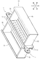
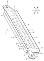
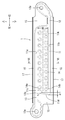
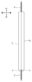
- ⁇ Battery cooler> 3 to 6 show the battery cooler 1 alone.
- two steel plates having flange portions 17 on the upper and lower sides are joined face-to-face to form one closed space, and hydrofluorocarbon (HFC) or hydro
- a refrigerant filling chamber 11 in which a refrigerant such as a fluoroolefin (HFO) is filled is configured.
- the closed space is formed by joining the upper and lower joints 16 and the left and right flat surfaces 15 by welding.
- a plurality of circular or spot-shaped joint portions 14 are also formed inside surrounded by the joint portion 16 and the flat surface portion 15.
- the joint portion 14 is formed by joining two steel plates to each other by welding. Laser welding is used for welding in this case.
- These joints 14 are staggered on both front and rear surfaces of the refrigerant filling chamber 11 to prevent the refrigerant filling chamber 11 from expanding and deforming due to the pressure of the refrigerant.
- a refrigerant outflow path 13 is formed in the upper left corner of the refrigerant filling chamber 11 to allow the vaporized refrigerant to flow out by receiving heat from the cell 6.
- the refrigerant outflow passage 13 projects outward from the left end of the refrigerant filling chamber 11.
- a communication hole 13a is formed at the protruding end of the refrigerant outflow passage 13, and the communication hole 13a of the refrigerant outflow passage 13 is connected to the condenser 3 via the flow path 4 as shown in FIG.
- a refrigerant inflow path 12 is formed in which the refrigerant condensed by the condenser 3 and cooled and circulated flows into the refrigerant filling chamber 11.
- the refrigerant inflow path 12 projects outward from the right end of the refrigerant filling chamber 11.
- a communication hole 12a is formed at the protruding end of the refrigerant inflow path 12, and the communication hole 12a of the refrigerant inflow path 12 is connected to the condenser 3 via the flow path 5 as shown in FIG.
- the refrigerant vaporized by receiving the heat of each cell 6 flows out from the refrigerant outflow passage 13, and passes through the flow path 4 as shown by the arrow in FIG. Sent to 3.
- the refrigerant condensed, cooled by the condenser 3, and liquefied again is circulated from the refrigerant inflow path 12 shown in FIG. 3 to the refrigerant filling chamber 11 through the flow path 5 as shown by the arrow in FIG.
- each cell 6 in contact with the surface of the refrigerant filling chamber 11 is cooled.
- the refrigerant liquefied in the refrigerant filling chamber 11 is maintained at the liquid level 11k shown by the alternate long and short dash line in FIG.
- the joint portions 14 staggered in two rows above and below are arranged so that the distance between the welded portions of the two steel plates including the joint portion 16 and the flat surface portion 15 is substantially equal.
- the stress due to the internal pressure of the refrigerant filling chamber 11 applied by the refrigerant is prevented from being concentrated on a part of each welded portion.
- the plurality of joints 14 are arranged in the region AR extending in the vertical direction in a strip shape with a predetermined width along the bottom surface 11b of the refrigerant filling chamber 11, and the refrigerant inflow passages are arranged on both the upper and lower outer sides of the region AR. 12 and the refrigerant outflow passage 13 are arranged.
- the refrigerant flowing from the refrigerant inflow path 12 into the refrigerant filling chamber 11 flows along the bottom surface 11b, and the joint portion 14 does not become a resistance to the inflow of the refrigerant.
- the refrigerant flowing out from the refrigerant filling chamber 11 to the refrigerant inflow path 12 flows along the top surface 11a, and the joint portion 14 does not become a resistance to the outflow of the refrigerant.
- an outflow side wall surface 11d rising upward from the bottom surface 11b of the refrigerant filling chamber 11 toward the connecting portion 13b of the refrigerant outflow passage 13 is formed.
- the outflow side wall surface 11d is formed with an inclined surface 11e in which the inner surface of the refrigerant filling chamber 11 is inclined downward from the horizontal direction.
- the inclined surface 11e is formed in the entire area of the outflow side wall surface 11d, that is, in a range from a position adjacent to the bottom surface 11b to a position adjacent to the connecting portion 13b.
- the battery cooler 1 is used in an environment where the battery cooler 1 is inclined or vibrates together with the assembled battery and the unvaporized refrigerant at the liquid level 11k flows toward the refrigerant outflow passage 13, the flow is caused by the inclined surface 11e. It is suppressed that the unvaporized refrigerant is bounced off and leaks from the refrigerant outflow passage 13.
- the inclined surface 11e is in the horizontal direction so as to secure a space for welding the end plate 22 to the flat surface portion 15 and to secure the surface of the refrigerant filling chamber 11 in contact with the cell 6 adjacent to the outflow side wall surface 11d.
- the inclination angle and length are set so as to form within the width ⁇ 1.
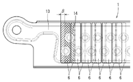
- the plurality of joints 14 staggered in two rows above and below are arranged so that the joints 14a and 14b adjacent to the outflow side wall surface 11d are inclined along the inclined surface 11e.
- the unvaporized refrigerant is a refrigerant as compared with the case where the joints 14 are not staggered and the two upper and lower joints 14 are arranged vertically in the vertical direction. It is possible to suppress the flow toward the outflow path 13. This is because the lower joint portion 14b arranged close to the outflow side wall surface 11d serves as a resistance for the flow of the unvaporized refrigerant toward the refrigerant outflow passage 13.
- FIG. 7 shows the misalignment of the cell 6 with respect to the battery cooler 1 due to the variation in the assembly of the cell 6.
- FIG. 8 shows a case where the upper and lower joints 14 are arranged in the vertical direction as a comparative example of the battery cooler 1 of the above-described embodiment. The misalignment of the cell 6 with respect to the battery cooler is shown. Both FIGS. 7 and 8 show the case where the misalignment ⁇ occurs. At this time, as shown in FIGS. 7 and 8, the amount of variation in the cooling surface area of the battery cooler 1 with which each cell 6 comes into contact differs due to the misalignment due to the difference in the arrangement of the joint portions 14. In the case of FIGS.
- the cooling surface of the battery cooler 1 is a surface excluding a recessed portion due to the formation of the joint portion 14 in the raised region surrounded by the joint portion 16 and the flat surface portion 15.
- the cooling surface of the battery cooler 1 in contact with the leftmost cell 6 is hatched.
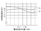
- FIG. 9 is a graph showing the fluctuation of the cooling surface area of the leftmost cell 6.
- Graph A of FIG. 9 is the case of the staggered arrangement of FIG. 7, and graph B is the case of the arrangement of FIG.
- A has less variation in the cooling surface area of the battery cooler 1 with respect to the amount of misalignment than in the case of the arrangement of FIG. That is, by arranging the joints 14 in a staggered manner, it is possible to suppress fluctuations in the cooling performance of the cell 6 by the battery cooler 1 due to variations in the assembly of the cell 6.
- FIG. 10 shows a battery cooler 1 as another embodiment.
- an outflow side wall surface 11f having a shape different from that of the outflow side wall surface 11d in FIG. 4 is used.
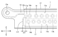
- the outflow side wall surface 11f rises substantially vertically from the bottom surface 11b of the refrigerant filling chamber 11 toward the connection portion 13b of the refrigerant outflow passage 13, and is bent in a convex shape to the right at the lower part of the connection portion 13b. Due to this bent shape, an inclined surface 11g is formed in the lower part of the connecting portion 13b (position adjacent to the connecting portion 13b).
- the inner surface of the refrigerant filling chamber 11 of the outflow side wall surface 11f is inclined downward from the horizontal direction. Since the inclined surface 11g is formed on the outflow side wall surface 11f in this way, even if the unvaporized refrigerant at the liquid level 11k flows toward the refrigerant outflow passage 13, the flow is repelled by the inclined surface 11g. It is suppressed that the unvaporized refrigerant leaks from the refrigerant outflow passage 13.
- the outflow side wall surface 11f provided with the inclined surface 11g can both secure a space for welding the end plate 22 and secure a cooling surface for the end cell 6 as in the case of FIG. It is within the range of a predetermined width ⁇ 2.
- FIG. 11 shows a battery cooler 1 as yet another embodiment.
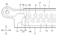
- the outflow side wall surface 11h having a shape different from that of the outflow side wall surfaces 11d and 11f in FIGS. 4 and 10 is used.
- the outflow side wall surface 11h rises upward while curving from the bottom surface 11b of the refrigerant filling chamber 11 toward the connection portion 13b of the refrigerant outflow passage 13 in a convex shape to the left, and has a convex shape to the right at the lower part of the connection portion 13b. It is bent. Due to this bent shape, an inclined surface 11j is formed in the lower part of the connecting portion 13b.
- the inclined surface 11j is formed at a boundary (position adjacent to the connecting portion 13b) between the curved shape convex on the left side and the bent shape convex on the right side, and the inner surface of the refrigerant filling chamber 11 of the outflow side wall surface 11h is from the horizontal direction. It is tilted downward. Since the inclined surface 11j is formed on the outflow side wall surface 11h in this way, even if the unvaporized refrigerant at the liquid level 11k flows toward the refrigerant outflow passage 13, the flow is repelled by the inclined surface 11j. It is suppressed that the unvaporized refrigerant leaks from the refrigerant outflow passage 13.
- the outflow side wall surface 11h provided with the inclined surface 11j can both secure a space for welding the end plate 22 and secure a cooling surface for the end cell 6 as in the case of FIG. It is within the range of a predetermined width ⁇ 3.
- the battery cooler 1 may be made of copper, aluminum, or the like instead of the steel plate.
- the joint portion 14 may have another shape such as a quadrangle or a hexagon instead of being circular.
- either the left or right end plate 22 may be slidable without being fixed to the battery cooler 1 or the holding frame 21.
- the cell cells 6 in each row may be bound by a stretchable binding band together with two end plates 22 facing each other with the cells 6 sandwiched between the left and right sides. Further, the cell cells 6 forming the two rows may be bound by the same binding band together with the battery cooler 1 sandwiched between the rows and the holding frame 21 facing the two rows.
- the cells 6 are arranged in two rows and illustrated, as another embodiment, they may be arranged in three or more rows. In that case, a plurality of battery coolers 1 can be arranged between adjacent rows.
- the outflow side wall surfaces 11d, 11f, and 11h rising from the bottom surface 11b of the refrigerant filling chamber 11 toward the connection portion 13b of the refrigerant outflow passage 13 are inclined downward from the horizontal direction to the inner surface of the refrigerant filling chamber 11.
- the surfaces 11e, 11g, and 11j are provided. Therefore, even if the battery is used in an environment where the battery is inclined or vibrates and the unvaporized refrigerant flows toward the refrigerant outflow passage 13, the flow is blocked by the inclined surfaces 11e, 11g, 11j and is not vaporized. The leakage of the refrigerant from the refrigerant outflow path 13 is suppressed.
- the joints 14 are staggered, even if the position of the cell 6 with respect to the refrigerant filling chamber 11 when it is used as an assembled battery changes from the initially assumed position due to the assembly variation, the refrigerant is filled. It is unlikely that the joint portion 14 of the chamber 11 is unevenly arranged on the contact surface of a part of the cell cells 6, and the fluctuation of the contact area due to the above-mentioned assembly variation is suppressed. Therefore, fluctuations in the cooling capacity of each unit cell 6 of the refrigerant filling chamber 11 are suppressed.
- the joints 14b adjacent to the outflow side wall surfaces 11d, 11f, and 11h also suppress the outflow of unvaporized refrigerant from the refrigerant outflow passage 13.
- the refrigerant flowing in from the refrigerant inflow path 12 flows along the bottom surface 11b at the lower part of the refrigerant filling chamber 11. Further, the refrigerant flowing out from the refrigerant outflow passage 13 flows along the top surface 11a at the upper part of the refrigerant filling chamber 11.
- the joint portion 14 is arranged in the region AR sandwiched between the refrigerant inflow path 12 and the refrigerant outflow path 13. Therefore, the inflow resistance of the refrigerant from the refrigerant inflow path 12 and the outflow resistance of the refrigerant from the refrigerant outflow path 13 can be suppressed.
- the horizontal width thereof is suppressed to the predetermined widths ⁇ 1, ⁇ 2, ⁇ 3, so that the lower part of the refrigerant outflow passage 13 is formed. It is possible to secure a flat surface in which the end plate 22 (wall body forming the housing) abuts on the flat surface portion 15 of the above, and it is possible to secure a cooling area for the cell unit 6 arranged adjacent to the end plate 22.
Landscapes
- Engineering & Computer Science (AREA)
- Chemical & Material Sciences (AREA)
- Chemical Kinetics & Catalysis (AREA)
- Electrochemistry (AREA)
- General Chemical & Material Sciences (AREA)
- Manufacturing & Machinery (AREA)
- Mechanical Engineering (AREA)
- Sustainable Energy (AREA)
- Sustainable Development (AREA)
- Power Engineering (AREA)
- Transportation (AREA)
- Life Sciences & Earth Sciences (AREA)
- Physics & Mathematics (AREA)
- Thermal Sciences (AREA)
- General Engineering & Computer Science (AREA)
- Secondary Cells (AREA)
- Battery Mounting, Suspending (AREA)
Abstract
Description
図1は、ひとつの実施形態としての電池冷却器を備えた組電池を示す。この組電池は、電気自動車等の電動車に用いられるものであり、複数の単電池6が互いに直列接続された状態で筐体2に囲まれて一体化されている。図1では、上下方向を重力方向として組電池を電動車に搭載した状態における各方向を矢印により示している。以下の説明において、方向に関する記述は、この矢印により示す方向を基準として行う。図1以外の図においても同様である。
図3~6は、電池冷却器1を単独で示す。電池冷却器1は、図6のように上下にフランジ部17を備えた2枚の鋼板を面合せで接合して一つの密閉空間が形成され、その密閉空間内にハイドロフルオロカーボン(HFC)やハイドロフルオロオレフィン(HFO)などの冷媒が充填される冷媒充填室11が構成されている。密閉空間は、上下の接合部16と左右の平面部15が溶接にて接合されることにより形成されている。また、接合部16及び平面部15により囲まれた内部にも円形あるいはスポット状の複数の接合部14が形成されている。接合部14は、接合部16及び平面部15と同様、2枚の鋼板が溶接にて互いに接合されることにより形成されている。この場合の溶接はレーザー溶接が用いられている。これらの接合部14は、冷媒充填室11の前後両表面上で千鳥配置されており、冷媒の圧力により冷媒充填室11が膨張変形するのを抑制している。
図10は、別の実施形態としての電池冷却器1を示す。この実施形態では、図4の流出側壁面11dとは異なる形状の流出側壁面11fを用いている。流出側壁面11fは、冷媒充填室11の底面11bから冷媒流出路13の接続部13bに向けて略垂直に立ち上がり、接続部13bの下部で右側に凸の形状で屈曲している。この屈曲形状により接続部13bの下部(接続部13bに隣接した位置)に傾斜面11gが形成されている。傾斜面11gは、流出側壁面11fの冷媒充填室11内側面が水平方向より下方に向けて傾斜されている。このように流出側壁面11fに傾斜面11gが形成されているため、液位11kにある気化していない冷媒が冷媒流出路13に向けて流れても、その流れは傾斜面11gにより跳ね返され、気化していない冷媒が冷媒流出路13から漏れ出ることが抑制される。なお、傾斜面11gを備えた流出側壁面11fは、図4の場合と同様に、エンドプレート22を溶接するためのスペースの確保と最も端の単電池6のための冷却表面の確保を両立可能な所定の幅α2の範囲内にある。
別の実施形態として、電池冷却器1は、鋼板に代えて、銅、アルミニウム等によって構成してもよい。
実施形態によっては、冷媒充填室11の底面11bから冷媒流出路13の接続部13bに向けて立ち上がる流出側壁面11d、11f、11hの冷媒充填室11内側面に水平方向より下方に向けられた傾斜面11e、11g、11jを備える。そのため、電池が傾斜、又は振動する環境で使用されて、気化していない冷媒が冷媒流出路13に向けて流れても、その流れは傾斜面11e、11g、11jにより阻止され、気化していない冷媒が冷媒流出路13から漏れ出ることが抑制される。
Claims (6)
- 組電池を成す複数の単電池の側面間に挟んで配置される電池冷却器であって、
対向する前記単電池間に挟まれてそれらの単電池の熱を受ける位置に配置された、冷媒が充填されるための冷媒充填室と、
該冷媒充填室の下部に接続された、外部の凝縮器で凝縮された冷媒を前記冷媒充填室に流入させるための冷媒流入路と、
前記冷媒充填室の上部に接続された、前記冷媒充填室で前記単電池の熱を受けて気化した冷媒を前記凝縮器へ流出させるための冷媒流出路とを備え、
前記冷媒充填室は、両側に配置された前記単電池の側面に接触する対向する壁面を備えるとともに、冷媒の圧力による自らの膨張変形を抑制するように、前記対向する壁面同士を部分的に相互接合する少なくとも一つの接合部を備え、
前記冷媒充填室の底面から前記冷媒流出路の前記冷媒充填室に対する接続部に向けて上方に立ち上がる流出側壁面には、水平方向より下方に向けられた傾斜面を備える
電池冷却器。 - 請求項1の電池冷却器であって、
前記少なくとも一つの接合部は、複数個の接合部であり、それらが前記単電池に接する前記冷媒充填室の壁面に沿って千鳥配置されている電池冷却器。 - 請求項2の電池冷却器であって、
前記流出側壁面に隣接する前記接合部は、上下に並ぶ複数個の前記接合部のうち下側の接合部が上側の接合部に対して水平方向で前記流出側壁面側にずれて配置されることにより千鳥配置されている電池冷却器。 - 請求項3の電池冷却器であって、
前記接続部は、上下に並ぶ複数個の前記接合部のうち上側の前記接合部に対して水平方向で側部に位置し、
前記傾斜面は、前記接続部に隣接した位置に設けられている電池冷却器。 - 請求項1~4のいずれかの電池冷却器であって、
前記少なくとも一つの接合部は、前記冷媒充填室の底面に沿って延びる所定幅で帯状の領域内に配置されており、前記冷媒流入路及び前記冷媒流出路は、前記帯状の領域の上下両外側に配置されている電池冷却器。 - 請求項1から5のいずれかの電池冷却器であって、
前記冷媒流入路及び前記冷媒流出路は、前記冷媒充填室の対極位置に配置されて互いに離れる方向に突出しており、
前記冷媒流入路の上部、及び前記冷媒流出路の下部に、前記各単電池を保持する筐体を成す壁体を当接させるための平面部を一体に備えており、
前記流出側壁面は、前記平面部として前記壁体が当接する平面を確保可能とし、且つ前記壁体に隣接して配置される前記単電池に接する前記冷媒充填室の冷却面を確保可能とする水平方向の幅内に形成されている電池冷却器。
Priority Applications (3)
| Application Number | Priority Date | Filing Date | Title |
|---|---|---|---|
| US17/764,965 US12249700B2 (en) | 2019-09-30 | 2020-09-30 | Battery cooler |
| EP20873029.1A EP4040570B1 (en) | 2019-09-30 | 2020-09-30 | Battery cooler |
| CN202080068305.XA CN114450838B (zh) | 2019-09-30 | 2020-09-30 | 电池冷却器 |
Applications Claiming Priority (2)
| Application Number | Priority Date | Filing Date | Title |
|---|---|---|---|
| JP2019179194A JP7128165B2 (ja) | 2019-09-30 | 2019-09-30 | 電池冷却器 |
| JP2019-179194 | 2019-09-30 |
Publications (1)
| Publication Number | Publication Date |
|---|---|
| WO2021066010A1 true WO2021066010A1 (ja) | 2021-04-08 |
Family
ID=75272685
Family Applications (1)
| Application Number | Title | Priority Date | Filing Date |
|---|---|---|---|
| PCT/JP2020/037148 Ceased WO2021066010A1 (ja) | 2019-09-30 | 2020-09-30 | 電池冷却器 |
Country Status (5)
| Country | Link |
|---|---|
| US (1) | US12249700B2 (ja) |
| EP (1) | EP4040570B1 (ja) |
| JP (1) | JP7128165B2 (ja) |
| CN (1) | CN114450838B (ja) |
| WO (1) | WO2021066010A1 (ja) |
Families Citing this family (5)
| Publication number | Priority date | Publication date | Assignee | Title |
|---|---|---|---|---|
| US12017501B2 (en) * | 2019-11-18 | 2024-06-25 | Bollinger Motors, Inc. | Electric automotive vehicle |
| JP7521508B2 (ja) * | 2021-09-24 | 2024-07-24 | トヨタ自動車株式会社 | 蓄電装置 |
| JP7582141B2 (ja) * | 2021-09-24 | 2024-11-13 | トヨタ自動車株式会社 | 蓄電装置 |
| JP7716033B1 (ja) * | 2023-09-29 | 2025-07-31 | 日本製鉄株式会社 | バッテリユニット |
| US20250379284A1 (en) * | 2024-06-11 | 2025-12-11 | GM Global Technology Operations LLC | Decoupled superbeam design for manufacturability |
Citations (9)
| Publication number | Priority date | Publication date | Assignee | Title |
|---|---|---|---|---|
| JP2005121319A (ja) * | 2003-10-17 | 2005-05-12 | Toho Gas Co Ltd | 熱交換器 |
| JP2006012847A (ja) * | 2004-06-25 | 2006-01-12 | Samsung Sdi Co Ltd | 二次電池モジュール |
| JP2013157111A (ja) | 2012-01-27 | 2013-08-15 | Showa Denko Kk | 組電池の冷却兼加熱構造 |
| JP2014029232A (ja) * | 2012-07-31 | 2014-02-13 | Nippon Soken Inc | 冷却装置 |
| JP2015041418A (ja) * | 2013-08-20 | 2015-03-02 | トヨタ自動車株式会社 | 電池温度調節装置 |
| JP2017196966A (ja) * | 2016-04-26 | 2017-11-02 | 株式会社Soken | 車載用熱交換器 |
| JP2018501603A (ja) * | 2014-12-04 | 2018-01-18 | エルジー・ケム・リミテッド | 電池パック |
| JP2018041772A (ja) * | 2016-09-05 | 2018-03-15 | 株式会社デンソー | 熱交換器 |
| JP2019016584A (ja) * | 2017-03-16 | 2019-01-31 | 株式会社デンソー | 機器温調装置 |
Family Cites Families (6)
| Publication number | Priority date | Publication date | Assignee | Title |
|---|---|---|---|---|
| JP2007299637A (ja) * | 2006-04-28 | 2007-11-15 | Toyota Motor Corp | 電池冷却構造 |
| JP5742664B2 (ja) * | 2011-10-26 | 2015-07-01 | トヨタ自動車株式会社 | 組電池及び車両 |
| JP6224321B2 (ja) * | 2013-01-11 | 2017-11-01 | フタバ産業株式会社 | 組電池の拘束具、組電池の拘束部材、バッテリ |
| CN109844438B (zh) | 2016-10-12 | 2020-06-12 | 株式会社电装 | 蒸发器 |
| CN106972220B (zh) | 2017-05-16 | 2019-06-14 | 扬州三丰新能源科技有限公司 | 一种动力电池热管理机组 |
| JP7264118B2 (ja) * | 2020-06-05 | 2023-04-25 | トヨタ自動車株式会社 | 冷却器 |
-
2019
- 2019-09-30 JP JP2019179194A patent/JP7128165B2/ja active Active
-
2020
- 2020-09-30 CN CN202080068305.XA patent/CN114450838B/zh active Active
- 2020-09-30 WO PCT/JP2020/037148 patent/WO2021066010A1/ja not_active Ceased
- 2020-09-30 EP EP20873029.1A patent/EP4040570B1/en active Active
- 2020-09-30 US US17/764,965 patent/US12249700B2/en active Active
Patent Citations (9)
| Publication number | Priority date | Publication date | Assignee | Title |
|---|---|---|---|---|
| JP2005121319A (ja) * | 2003-10-17 | 2005-05-12 | Toho Gas Co Ltd | 熱交換器 |
| JP2006012847A (ja) * | 2004-06-25 | 2006-01-12 | Samsung Sdi Co Ltd | 二次電池モジュール |
| JP2013157111A (ja) | 2012-01-27 | 2013-08-15 | Showa Denko Kk | 組電池の冷却兼加熱構造 |
| JP2014029232A (ja) * | 2012-07-31 | 2014-02-13 | Nippon Soken Inc | 冷却装置 |
| JP2015041418A (ja) * | 2013-08-20 | 2015-03-02 | トヨタ自動車株式会社 | 電池温度調節装置 |
| JP2018501603A (ja) * | 2014-12-04 | 2018-01-18 | エルジー・ケム・リミテッド | 電池パック |
| JP2017196966A (ja) * | 2016-04-26 | 2017-11-02 | 株式会社Soken | 車載用熱交換器 |
| JP2018041772A (ja) * | 2016-09-05 | 2018-03-15 | 株式会社デンソー | 熱交換器 |
| JP2019016584A (ja) * | 2017-03-16 | 2019-01-31 | 株式会社デンソー | 機器温調装置 |
Non-Patent Citations (1)
| Title |
|---|
| See also references of EP4040570A4 |
Also Published As
| Publication number | Publication date |
|---|---|
| CN114450838A (zh) | 2022-05-06 |
| CN114450838B (zh) | 2024-01-05 |
| EP4040570B1 (en) | 2025-09-17 |
| US20220407147A1 (en) | 2022-12-22 |
| US12249700B2 (en) | 2025-03-11 |
| EP4040570A4 (en) | 2023-10-25 |
| JP7128165B2 (ja) | 2022-08-30 |
| EP4040570A1 (en) | 2022-08-10 |
| JP2021057187A (ja) | 2021-04-08 |
Similar Documents
| Publication | Publication Date | Title |
|---|---|---|
| JP7128165B2 (ja) | 電池冷却器 | |
| JP7151493B2 (ja) | 電池装置 | |
| JP6358872B2 (ja) | 発熱素子用沸騰冷却器 | |
| JP2017106668A (ja) | 熱交換器 | |
| KR20140138412A (ko) | 전기 자동차의 배터리 냉각 장치 | |
| JP2013254787A (ja) | 熱交換器及びその製造方法 | |
| JP6409836B2 (ja) | 蓄冷熱交換器 | |
| KR20180054382A (ko) | 배터리 열교환기 및 그를 갖는 배터리 팩 | |
| US11835297B2 (en) | Heat exchanger | |
| JP2011192730A (ja) | 冷却器、積層冷却器および中間プレート | |
| JP5920087B2 (ja) | 蓄冷熱交換器 | |
| JP2021096917A (ja) | 電池モジュール | |
| JP6809423B2 (ja) | ヘッダタンク及び熱交換器 | |
| JP2014020757A (ja) | 蓄冷熱交換器 | |
| JP6414504B2 (ja) | 熱交換器 | |
| JP7028637B2 (ja) | 平面型ヒートパイプ | |
| CN109696070B (zh) | 热交换器 | |
| CN106030235A (zh) | 热交换器 | |
| US12176506B2 (en) | Battery cold plate and chassis with interlocking joints | |
| JP4664114B2 (ja) | 多板式熱交換器 | |
| KR100389699B1 (ko) | 수냉식 열교환기 | |
| JP6089172B2 (ja) | 熱交換器 | |
| JP7331335B2 (ja) | 組立体 | |
| EP2960611A1 (en) | Production method for heat exchangers | |
| KR20220153825A (ko) | 열교환기 |
Legal Events
| Date | Code | Title | Description |
|---|---|---|---|
| 121 | Ep: the epo has been informed by wipo that ep was designated in this application |
Ref document number: 20873029 Country of ref document: EP Kind code of ref document: A1 |
|
| NENP | Non-entry into the national phase |
Ref country code: DE |
|
| ENP | Entry into the national phase |
Ref document number: 2020873029 Country of ref document: EP Effective date: 20220502 |
|
| WWG | Wipo information: grant in national office |
Ref document number: 17764965 Country of ref document: US |
|
| WWG | Wipo information: grant in national office |
Ref document number: 2020873029 Country of ref document: EP |