WO2021070339A1 - 保管庫 - Google Patents
保管庫 Download PDFInfo
- Publication number
- WO2021070339A1 WO2021070339A1 PCT/JP2019/040079 JP2019040079W WO2021070339A1 WO 2021070339 A1 WO2021070339 A1 WO 2021070339A1 JP 2019040079 W JP2019040079 W JP 2019040079W WO 2021070339 A1 WO2021070339 A1 WO 2021070339A1
- Authority
- WO
- WIPO (PCT)
- Prior art keywords
- unit
- production
- delivery
- storage
- delivered
- Prior art date
- Legal status (The legal status is an assumption and is not a legal conclusion. Google has not performed a legal analysis and makes no representation as to the accuracy of the status listed.)
- Ceased
Links
Images




Classifications
-
- H—ELECTRICITY
- H05—ELECTRIC TECHNIQUES NOT OTHERWISE PROVIDED FOR
- H05K—PRINTED CIRCUITS; CASINGS OR CONSTRUCTIONAL DETAILS OF ELECTRIC APPARATUS; MANUFACTURE OF ASSEMBLAGES OF ELECTRICAL COMPONENTS
- H05K13/00—Apparatus or processes specially adapted for manufacturing or adjusting assemblages of electric components
- H05K13/08—Monitoring manufacture of assemblages
- H05K13/086—Supply management, e.g. supply of components or of substrates
-
- H—ELECTRICITY
- H05—ELECTRIC TECHNIQUES NOT OTHERWISE PROVIDED FOR
- H05K—PRINTED CIRCUITS; CASINGS OR CONSTRUCTIONAL DETAILS OF ELECTRIC APPARATUS; MANUFACTURE OF ASSEMBLAGES OF ELECTRICAL COMPONENTS
- H05K13/00—Apparatus or processes specially adapted for manufacturing or adjusting assemblages of electric components
- H05K13/02—Feeding of components
- H05K13/021—Loading or unloading of containers
Definitions
- This specification discloses the technology related to storage.
- the storage described in Patent Document 1 stores the mounting head and the feeder device.
- the replacement support device described in Patent Document 1 is a mounting head and feeder device stored in a storage based on production job information and maintenance information when performing setup change to change the type of substrate to be produced. From among them, determine the mounting head and feeder device to be equipped on the component mounting machine.
- the replacement support device searches for a feeder device that holds a reel of a part type required for production after setup change. Further, the guide unit of the exchange support device guides the operator to the mounting head and the feeder device to be discharged from the storage.
- the setting control unit sets the suction nozzle required in the component mounting machine to the nozzle tray based on the information received from at least one of the component mounting machine and the management device. Set to.
- both supplies such as articles provided on the board by the board-to-board work machine and equipment that is detachably provided on the board-to-board work machine and used in the board-to-board work. Is required.
- the required combinations of supplies and equipment also change depending on the type of substrate product to be produced, it is necessary to have supplies and equipment that match the type of substrate product to be produced.
- the supplied items are stored in a state of being incorporated in the device, such as the reel and feeder device described above, the combination of the supplied items and the device at the time of delivery may be limited.
- this specification can store the supplied goods and the equipment, respectively, and can issue the goods and the equipment in association with the supplies used for the unit production in which the production of the same type of substrate product is specified. Disclosure of storage.
- This specification discloses a storage unit including a first storage unit, a second storage unit, a delivery unit, and a moving unit.
- the first storage unit stores an article provided on the substrate by a substrate working machine that performs a predetermined anti-board work on the substrate, and a supplied product that is at least one of the substrates before the article is provided.
- the second storage unit is detachably provided on the board-to-board work machine and stores equipment used in the board-to-board work.
- the delivery unit is the supply product used for the predetermined unit production included in the production plan in which the production of the same type of substrate product using the substrate working machine is specified and the order of the unit production is specified.
- the equipment is associated and shipped.
- the moving unit moves the supplied item stored in the first storage unit to the delivery unit, and moves the device stored in the second storage unit to the delivery unit.
- the above storage it is provided with a first storage unit, a second storage unit, a delivery unit, and a moving unit.
- the supplied items can be stored in the first storage unit
- the equipment can be stored in the second storage unit.
- the moving part moves the supplied items stored in the first storage part to the delivery part
- the equipment stored in the second storage part is moved to the delivery part, so that the delivery part moves. Supplies and equipment used for a given unit production can be associated and delivered.
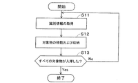
- FIG. 3A is a plan view of the storage cabinet of FIG. 3A. It is a front view which shows an example of the storage part of the storage of FIG. 3B. It is a block diagram which shows an example of the control block of a storage. It is a flowchart which shows an example of the control procedure in the warehousing work of supplies and equipment. It is a flowchart which shows an example of the control procedure in the delivery work of a supplied item and an apparatus.
- the storage 40 of this embodiment is provided in the substrate production facility 80.
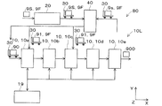
- the board production facility 80 includes a board work line 10L, a loading unit 20, a transport vehicle 30, and a storage 40.
- Board work line 10L In the board-to-board work line 10L, a predetermined board-to-board work is performed on the board 90.
- the type and number of the substrate working machines 10 constituting the substrate working line 10L are not limited.
- the board-to-board work line 10L of the present embodiment is a plurality (five) board-to-board work of a printing machine 10a, a printing inspection machine 10b, a component mounting machine 10c, a reflow furnace 10d, and an appearance inspection machine 10e.
- the machine 10 is provided, and the substrate 90 is conveyed in this order by the substrate conveying device.
- the printing machine 10a prints solder at mounting positions of a plurality of parts on the substrate 90.
- the solder printed on the substrate 90 has a predetermined viscosity, and the solder functions as a bonding material for joining the substrate 90 and the components mounted on the substrate 90.
- the solder is stored in the solder storage container 91c.
- the solder containing container 91c for example, a bottomed tubular or tube-shaped sealable container can be used.
- the printing inspection machine 10b inspects the printing state of the solder printed by the printing machine 10a.
- the component mounting machine 10c mounts a plurality of components on the substrate 90 on which the solder is printed.
- the number of component mounting machines 10c may be one or a plurality. When a plurality of component mounting machines 10c are provided, the plurality of component mounting machines 10c can share and mount the plurality of components on the substrate 90.
- the component mounting machine 10c is provided with a component supply device that supplies components to be mounted on the substrate 90.
- the parts supply device can supply parts by using, for example, a feeder 95b, a tray 91b, or the like provided with the reel 91a shown in FIG.
- a component tape (carrier tape) for accommodating components is wound around the reel 91a.
- the reel 91a is rotatably and detachably provided on the feeder 95b, and the tip end portion of the component tape is pulled out to the component extraction portion provided on the feeder 95b, and the components are sequentially supplied.
- the reel 91a can supply relatively small parts such as chip parts.
- a plurality of parts are arranged on the tray 91b.
- the tray 91b can supply relatively large parts such as QFP (Quad Flat Package) and BGA (Ball Grid Array). Further, the parts supply device can also supply the parts housed in the parts storage container 91d, for example. A plurality of parts are stored in the parts storage container 91d without being arranged.
- a mounting head 95a is detachably (replaceable) provided on the component mounting machine 10c.
- the mounting head 95a is provided with at least one holding member 95c detachably (replaceable).
- the holding member 95c for example, a suction nozzle, a chuck, or the like can be used.
- the component mounting machine 10c uses the mounting head 95a and the holding member 95c to collect and hold the components supplied by the component supply device, and mount the components on the positioned substrate 90.
- the holding member 95c can be appropriately changed according to the type of the component in the mounting process for mounting the component on the substrate 90.
- the holding member 95c housed in the holding member housing device 95d may be mounted on the mounting head 95a. it can.
- the holding member accommodating device 95d can detachably (replaceably) accommodate a plurality of holding members 95c, and is detachably (replaceably) mounted at a predetermined position in the component mounting machine 10c.
- the reflow furnace 10d heats the substrate 90 on which a plurality of parts are mounted by the component mounting machine 10c, melts the solder, and performs soldering.
- the visual inspection machine 10e inspects the mounting state of a plurality of parts mounted by the component mounting machine 10c.
- the board-to-board work line 10L uses a plurality of (five) board-to-board work machines 10 to sequentially convey the boards 90 and execute a production process including an inspection process to produce the board product 900. Can be done.
- the board working line 10L includes, for example, a board working machine 10 such as a functional inspection machine, a buffer device, a board supply device, a board reversing device, a shield mounting device, an adhesive coating device, and an ultraviolet irradiation device, if necessary. You can also prepare.
- a board working machine 10 such as a functional inspection machine, a buffer device, a board supply device, a board reversing device, a shield mounting device, an adhesive coating device, and an ultraviolet irradiation device, if necessary. You can also prepare.
- a plurality of (five) anti-board work machines 10 and management devices 19 constituting the anti-board work line 10L are provided so as to be able to communicate with each other by a wired or wireless communication unit.
- the management device 19 controls a plurality of (five) anti-board work machines 10 constituting the anti-board work line 10L, and monitors the operating status of the anti-board work line 10L.
- the management device 19 stores various control data for controlling a plurality of (five) anti-board working machines 10.
- the management device 19 transmits control data to each of the plurality of (five) anti-board working machines 10. Further, each of the plurality (five) anti-board working machines 10 transmits the operating status and the production status to the management device 19.
- Loading unit 20 and transport vehicle 30 At least one of the article 91 provided on the substrate 90 by the substrate working machine 10 that performs a predetermined anti-board work on the substrate 90 and the substrate 90 before the article 91 is provided is referred to as a supplied product 9S. .. Further, a device 9F that is detachably provided on the board-to-board work machine 10 and is used in the board-to-board work.
- the board-to-board work line 10L is provided with a printing machine 10a.
- the solder stored in the solder storage container 91c corresponds to the article 91.
- the squeegee and the mask correspond to the device 9F.
- the printing head and the dispense head correspond to the device 9F.
- the board-to-board work line 10L is equipped with a component mounting machine 10c.
- the parts housed in the parts tape wound around the reel 91a correspond to the article 91.
- the parts housed in the tray 91b correspond to the article 91.
- the parts housed in the parts storage container 91d correspond to the article 91.
- the mounting head 95a detachably provided on the component mounting machine 10c corresponds to the device 9F.
- the feeder 95b detachably provided on the component mounting machine 10c corresponds to the device 9F.
- the holding member 95c detachably provided on the component mounting machine 10c via the mounting head 95a corresponds to the device 9F.
- the holding member accommodating device 95d detachably provided on the component mounting machine 10c corresponds to the device 9F.
- the board work line 10L is equipped with a printing inspection machine 10b. Further, the substrate working line 10L is provided with a visual inspection machine 10e. In these cases, for example, the inspection head that inspects the inspection target (solder or parts) corresponds to the device 9F.
- the printing machine 10a shown in FIG. 1 carries the substrate 90 before the article 91 described above is provided. The substrate 90 is included in the supplied product 9S.
- the supplied item 9S arrives at the arriving section 20, a predetermined arriving operation is performed. Then, the supplied product 9S is stored in the storage case 93, mounted on the transport vehicle 30, and transported to the storage 40, for example. The supplied product 9S is stored in the storage 40 and then supplied to the substrate work line 10L as needed.
- the supply product 9S is provided with the identification code 92.
- the identification code 92 stores identification information for identifying the supplied product 9S.
- the identification code 92 for example, a one-dimensional code, a two-dimensional code, a wireless tag, or the like can be used.
- the worker of the arriving unit 20 issues identification information using, for example, a management device.
- the operator uses a bar code reader or the like to read the bar code or the like provided on the supply product 9S by the supplier (vendor). Then, the worker can also acquire the supply product information of the supply product 9S from the database in which the supply product information regarding the supply product 9S is registered.
- the operator uses the management device to store at least the identification information among the identification information and the supply information in the identification code 92.
- the worker of the loading unit 20 attaches the identification code 92 in which at least the identification information is stored to the supply item 9S, and stores the supply item 9S in the storage case 93.
- the storage case 93 may take various forms as long as it can store at least one supply 9S.
- the storage case 93 is provided with a specific code 94.
- the specific code 94 stores specific information that identifies the storage case 93.
- a one-dimensional code, a two-dimensional code, a wireless tag, or the like can be used.
- the operator reads the specific code 94 using a reading device and reads the identification code 92 provided on the supply product 9S using a reading device.
- a correspondence relationship between the specific information that identifies the storage case 93 that houses the supply product 9S and the identification information that identifies the supply product 9S is generated, and the correspondence relationship is transmitted to the storage unit of the management device 19. Be remembered. The same applies to the case where the device 9F arrives at the arrival unit 20 as described above for the supply item 9S.
- FIG. 2 is a plan view showing an example of a stored state in which the supplied product 9S and the device 9F are stored in the storage case 93. Specifically, the figure shows an example of a state in which a reel 91a around which a component tape accommodating a component corresponding to an article 91 is wound is housed in a storage case 93. Further, the figure shows an example of a state in which the tray 91b containing the parts corresponding to the article 91 is housed (loaded) in the storage case 93. The tray 91b is housed in a packaging bag, and the identification code 92 is attached to the packaging bag of the tray 91b.
- the figure shows an example of a state in which the solder storage container 91c containing the solder corresponding to the article 91 is housed in the storage case 93. Further, the figure shows an example of a state in which the substrate 90 before the article 91 is provided is housed in the storage case 93.
- the figure shows an example of a state in which the mounting head 95a, the feeder 95b, the holding member 95c, and the holding member accommodating device 95d corresponding to the device 9F are accommodated in the accommodating case 93.
- the mounting head 95a and the feeder 95b are housed in a storage case 93, respectively.
- the holding member 95c can be accommodated in a storage space for detachably accommodating the holding member 95c, and can also be detachably accommodated in the holding member accommodating device 95d.
- the storage case 93 can also store the supplied product 9S and the equipment 9F together.
- a parts storage container 91d for storing parts corresponding to the article 91, a holding member 95c corresponding to the device 9F, and a holding member storage device 95d are housed together.
- the accommodating case 93 is provided with a cushioning material to reduce vibration applied to the supplied product 9S and the device 9F during transportation or the like.
- the worker of the loading unit 20 mounts the storage case 93 in which at least one of the supplied product 9S and the equipment 9F is housed on the transport vehicle 30.
- the transport vehicle 30 can be towed by, for example, an operator.
- an automatic guided vehicle AGV: Automatic Guided Vehicle
- the automatic guided vehicle 30 of the present embodiment is an automatic guided vehicle.
- the board-to-board work line 10L, the loading unit 20, the transport vehicle 30, and the storage 40 are provided so as to be able to communicate with each other by a wired or wireless communication unit.
- the management device 19 transmits a transport command to the transport vehicle 30.
- the transport command includes the transport destination of the storage case 93.
- the management device 19 selects a storage 40 capable of storing the storage case 93 and determines a transport destination.
- the transport vehicle 30 transports the storage case 93 to the storage 40 designated as the transport destination.
- the transport vehicle 30 can also transport at least one of the supplied product 9S and the equipment 9F without using the storage case 93. Further, the operator can also transport at least one of the supplied product 9S and the equipment 9F without using the transport vehicle 30. Further, at least a part of the work performed by the above-mentioned worker can be automated by using a transfer device (for example, a belt conveyor or the like), an actuator (for example, a robot arm or the like), a management device, or the like.
- a transfer device for example, a belt conveyor or the like
- an actuator for example, a robot arm or the like
- a management device or the like.
- Storage 40 In this way, at least one of the supplied product 9S and the equipment 9F arriving at the receiving unit 20 is transported to the storage 40. Further, at least one of the supplied items 9S and the equipment 9F that are no longer needed on the board-to-board work line 10L is transported to the storage 40. The supplied product 9S and the equipment 9F transported to the storage 40 are stored in the storage 40 and, if necessary, transported to the substrate work line 10L.
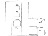
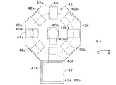
- the storage 40 may take various forms as long as it can store the supplied product 9S and the equipment 9F. As shown in FIGS. 3A and 3B, the storage 40 of the present embodiment is formed in an octagonal column shape, for example. Further, as shown in FIGS. 3A to 3C, the storage 40 includes the first opening 41a, the second opening 41b, the storage 42, the delivery 43, the control device 40a, and the moving device 40b. It has.
- the storage unit 42 includes a first storage unit 42a and a second storage unit 42b, and may further include a third storage unit 42c.
- the warehousing section 43 includes a first warehousing section 43a and a second warehousing section 43b.
- the delivery unit 43 can be formed on, for example, a trolley 46 or a shelf 47.
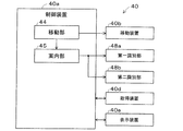
- the control device 40a includes a moving unit 44 when regarded as a control block.
- the control device 40a may further include a guide unit 45.
- the storage 40 may include at least one of a work space 40c, an acquisition device 40d, a display device 40e, and a delivery space 40f.
- the storage 40 of the present embodiment includes all the above-mentioned parts and devices.
- the delivery section 43 is formed on the shelf 47.
- FIGS. 3A and 3B Schematic configuration of storage 40 As shown in FIGS. 3A and 3B, a first opening 41a is provided on the front surface of the storage 40, and a second opening 41b is provided on the side surface of the storage 40. There is.
- the supply product 9S and the equipment 9F enter or leave the first opening 41a.
- the first opening 41a is formed to be larger than the supply product 9S and the equipment 9F so that the supply product 9S and the equipment 9F can be stored or delivered.
- At least one of the supplied product 9S and the device 9F can be stored or delivered through the first opening 41a in a state of being housed in the storage case 93.
- the first opening 41a is formed to be larger than the storage case 93 so that the storage case 93 can be stored or discharged.
- Supply product 9S and equipment 9F are delivered from the second opening 41b. The same applies to the second opening 41b as described above for the first opening 41a.
- the acquisition device 40d is provided in the first opening 41a.
- the acquisition device 40d reads the identification code 92 provided on the supply product 9S to acquire the identification information for identifying the supply product 9S.
- the acquisition device 40d reads the identification code 92 provided on the device 9F to acquire the identification information for identifying the device 9F.
- a known reading device for example, a one-dimensional code, a code reader that reads a two-dimensional code, a wireless reader that performs wireless communication with a wireless tag, or the like
- a known reading device for example, a one-dimensional code, a code reader that reads a two-dimensional code, a wireless reader that performs wireless communication with a wireless tag, or the like.
- the acquisition device 40d is installed above the work space 40c provided in the vicinity of the first opening 41a.
- the acquisition device 40d reads the identification code 92 provided in the supply product 9S when the supply product 9S is received through the first opening 41a, and acquires at least the identification information among the identification information and the supply product information. ..
- the acquisition device 40d reads the identification code 92 provided on the device 9F and reads at least the identification information and the device information related to the device 9F. To get.
- the acquisition device 40d can also acquire specific information by reading the specific code 94 provided in the storage case 93 when the storage case 93 is stored through the first opening 41a.
- the acquisition device 40d may acquire the identification information of at least one of the supply item 9S and the device 9F housed in the storage case 93 based on the correspondence between the specific information and the identification information. it can.
- the acquisition device 40d is provided only in the first opening 41a.
- the first opening 41a is a warehousing / delivery port in which the supplied item 9S and the device 9F can be stored or delivered
- the second opening 41b is a warehousing port in which the supplied item 9S and the device 9F can be delivered. is there.
- the storage unit 42 may take various forms as long as it can store both the supplied product 9S and the device 9F. As shown in FIG. 3B, the storage portions 42 of the present embodiment are arranged in a circular shape in the vertical direction (Z-axis direction). Further, as shown in FIG. 3C, the storage unit 42 includes a first storage unit 42a for storing the supplied product 9S and a second storage unit 42b for storing the device 9F.
- the number and arrangement of the first storage unit 42a and the second storage unit 42b can be changed as appropriate.
- at least one of the plurality of storage units 42 has only the first storage unit 42a
- the other at least one storage unit 42 of the plurality of storage units 42 has only the second storage unit 42b.
- FIG. 3B in the storage 40 of the present embodiment, a part of the first storage portion 42a or the second storage portion 42b is abolished, and a work space 40c and a delivery space 40f are secured. ..
- the shape and size (width, depth, and height) of the first storage unit 42a can be set according to the supplied product 9S to be stored, and the second storage unit 42b can be set according to the equipment 9F to be stored.
- the shape and size (width, depth, and height) can be set.
- the storage unit 42 can also store the storage case 93 that houses at least one of the supplied product 9S and the device 9F.
- the shape and size (width, depth, and height) of the first storage portion 42a and the second storage portion 42b can be set according to the storage case 93.
- the shape and size (width, depth, and height) of the storage case 93 are set according to the shape and size (width, depth, and height) of the first storage portion 42a and the second storage portion 42b. You can also do it.
- the storage unit 42 can also include a third storage unit 42c that stores both the supplied product 9S and the device 9F.
- the storage case 93 containing both the supply item 9S and the device 9F (the device 9F and the device 9S are housed together) is housed in the third storage section 42c.
- the supply item 9S, the device 9F and the storage case 93 can be stored in the compatible storage unit 42.
- the storage unit 42 in which the supplied product 9S is stored is the first storage unit 42a.
- the storage unit 42 in which the device 9F is stored is the second storage unit 42b.
- the storage unit 42 in which both the supplied product 9S and the device 9F are stored is the third storage unit 42c.
- any storage 40 may be stored as long as it is a storage 40 having a compatible storage unit 42.
- the production plan stipulates the order of unit production UJ0 in which the production of the same type of substrate product 900 using the substrate working machine 10 is specified.
- a plurality of types for example, three types
- substrates are produced in the order of the production of the first type substrate product 900, the production of the second type substrate product 900, the production of the third type substrate product 900, and the like.
- the production plan may include the number of substrate products 900 to be produced, the production time, the delivery date, the supplied product 9S to be used, the equipment 9F, and the like.
- the production plan may include the work lines for the substrate 10L to be used.
- the production plan may be a production plan for one type of substrate product 900.
- the delivery unit 43 issues the supply 9S and the equipment 9F used for the predetermined unit production UJ0 included in the production plan in association with each other.
- the warehousing section 43 of the present embodiment includes a first warehousing section 43a and a second warehousing section 43b.
- the supply product 9S used for the unit production UJ0 is delivered to the first delivery unit 43a.
- the device 9F used for the same unit production UJ0 as the supply product 9S delivered from the first delivery section 43a is delivered to the second delivery section 43b.
- the first delivery section 43a and the second delivery section 43b can be formed on, for example, a trolley 46 or a shelf 47 capable of holding the supplied item 9S and the device 9F.
- the dolly 46 or the shelf 47 may take various forms as long as it can hold the supply 9S and the device 9F.
- the first delivery section 43a and the second delivery section 43b are formed on a shelf 47 having a plurality of storage spaces.
- the first delivery section 43a is formed in the upper space of the shelf 47
- the second delivery section 43b is formed in the lower space of the shelf 47.
- the second opening 41b shown in FIG. 3B is provided with a door portion.
- the upper space and the lower space of the shelf 47 and the delivery space 40f can communicate with each other through the second opening 41b.
- the door portion is controlled to be in the open state by the control device 40a when the supplied product 9S and the device 9F are delivered.
- the supply product 9S and the equipment 9F used for the same unit production UJ0 are associated and delivered through the second opening 41b.
- the door portion is controlled to be closed by the control device 40a.
- the control device 40a includes a known arithmetic unit and a storage device, and constitutes a control circuit.
- the control device 40a is provided so as to be able to communicate with the mobile device 40b, the acquisition device 40d, and the display device 40e, and these can be controlled.
- the control device 40a can also control the opening and closing of the doors provided in the first opening 41a and the second opening 41b, respectively. Further, the control device 40a can store the supply product information regarding the supply product 9S, and can notify the supply product information to the management device 19.
- the supplied product information includes the part type, the number of parts (remaining number), the reel diameter, the model and the supplier (vendor), the expiration date, etc. of the parts housed in the reel 91a.
- the control device 40a can store device information related to the device 9F, and can also notify the device information to the management device 19.
- the device information can include the number of times the mounting head 95a is used, the usage time, the used component mounting machine 10c, the maintenance time, and the like.
- the moving device 40b moves the supply product 9S to a predetermined first storage unit 42a when the supply product 9S is received through the first opening 41a, and moves the supply product 9S to the first storage unit 42a when the supply product 9S is delivered.
- the stored supply item 9S is moved to the delivery space 40f.
- the moving device 40b moves the device 9F to a predetermined second storage section 42b when the device 9F enters the warehousing through the first opening 41a, and moves to the second storage section 42b when the device 9F is delivered.
- the stored device 9F is moved to the delivery space 40f.
- the moving device 40b moves the storage case 93 to a predetermined first storage unit 42a, second storage unit 42b, or third storage unit 42c when the storage case 93 is stored through the first opening 41a. Further, the moving device 40b moves the storage case 93 stored in the first storage unit 42a, the second storage unit 42b, or the third storage unit 42c to the delivery space 40f when the storage case 93 is delivered.
- the moving device 40b of the present embodiment is provided inside the accommodating portion 42 in the vertical direction (Z-axis direction).
- the moving device 40b may take various forms as long as the object (supply item 9S and device 9F or storage case 93) can be moved.
- a robot arm articulated robot
- an elevating slide mechanism or the like can be used.
- the moving device 40b can include, for example, an elevating portion 40b1 and a gripping portion 40b2.
- the elevating portion 40b1 can rotate around an axis along the vertical direction (Z-axis direction), and can elevate and lower the grip portion 40b2 along the vertical direction (Z-axis direction).
- the grip 40b2 can move forward or backward and hold or release the object.
- the moving device 40b can store the object stored through the first opening 41a in the storage unit 42, and can move the object to the delivery space 40f.
- the moving device 40b can also move the object that has moved to the shipping space 40f to the shipping unit 43.
- the moving device 40b may be provided with a transport device (for example, a belt conveyor) in the delivery space 40f. In this case, the transport device can move the object that has moved to the delivery space 40f to the delivery unit 43.
- the moving device 40b can also move the supplied product 9S stored in the first storage unit 42a to the work space 40c provided in the first opening 41a when the supplied product 9S is delivered.
- the moving device 40b can move the device 9F stored in the second storage section 42b to the work space 40c provided in the first opening 41a when the device 9F is delivered.
- the mobile device 40b delivers both the supply item 9S and the device 9F
- the supply item 9S and the device 9F stored in the third storage unit 42c are placed in the work space 40c provided in the first opening 41a. You can also move. The same can be said for the case where at least one of the supply product 9S and the device 9F is housed in the storage case 93.
- At least one of the supplied product 9S and the device 9F is stored in a state of being housed in the storage case 93, and is delivered in a state of being housed in the storage case 93. Therefore, at least one of the supply item 9S and the device 9F housed in the storage case 93 can be easily moved, and the grip portion 40b2 of the moving device 40b can be easily shared regardless of the type of the supply item 9S and the device 9F. .. Further, by storing and delivering at least one of the supplied item 9S and the device 9F in the storage case 93, it becomes easy to manage at least one of the supplied item 9S and the device 9F, and the loss or the like can be caused. It can also be mitigated.
- the storage case 93 can store various supplies 9S and can store various devices 9F.
- the storage case 93 can also accommodate both the supply 9S and the equipment 9F (accommodate the equipment 9F and the equipment 9S together).
- the board working machine 10 is a component mounting machine 10c that mounts a component that is a supplied product 9S on a board 90 that is a supplied product 9S.
- the holding member 95c that can be held may be limited depending on the type of part, and it may be preferable to manage the part and the holding member 95c that can hold the part together.
- the holding member 95c which is a device 9F for collecting and holding the parts and mounting them on the substrate 90, and the parts that can be held by the holding member 95c are housed together in the storage case 93.
- the storage 40 includes a display device 40e.
- the display device 40e a known display device can be used, and various data are visually displayed by the operator.
- the display device 40e displays, for example, supply item information regarding the supply item 9S stored in the first storage unit 42a, device information regarding the device 9F stored in the second storage unit 42b, and the like according to the operation of the operator. To do.
- control device 40a can store the position information, the warehousing / delivery information, and the storage information of the supplied item 9S and the device 9F in the storage unit 42, and the display device 40e can also display these information.
- the location information indicates the storage location of the supplied product 9S and the equipment 9F.
- the warehousing / delivery information indicates the warehousing date / time and the warehousing date / time of the supplied item 9S and the device 9F.
- the storage information includes, for example, information such as the atmospheric temperature of the storage unit 42 and the humidity of the storage unit 42.
- the control device 40a stores the position information of the supply item 9S and the device 9F and the warehousing date and time when the supply item 9S and the device 9F are stored.
- the control device 40a stores the storage information during the storage of the supply product 9S and the device 9F.
- the control device 40a stores the delivery date and time of the supply item 9S and the device 9F at the time of delivery of the
- the display device 40e of the present embodiment is configured by a touch panel, and the display device 40e also functions as an input device that accepts various operations by an operator.
- the operator can also use a touch panel (display device 40e functioning as an input device) to specify desired supplies 9S and equipment 9F to be delivered from the storage 40.
- the storage 40 delivers the designated supplies 9S and equipment 9F.
- control device 40a includes a moving unit 44 and a guide unit 45 when regarded as a control block. Further, the control device 40a executes the control program according to the flowcharts shown in FIGS. 5A and 5B.
- FIG. 5A shows an example of a control procedure in the warehousing work of the supplied product 9S and the equipment 9F.
- the control device 40a uses the acquisition device 40d to acquire the identification information of the supply product 9S (step S11).
- the control device 40a can also acquire the identification information of the device 9F by using the acquisition device 40d when the device 9F is stored through the first opening 41a.
- control device 40a can also acquire the specific information of the accommodation case 93 by using the acquisition device 40d when the accommodation case 93 is stored through the first opening 41a. In this case, the control device 40a acquires the identification information of at least one of the supply item 9S and the device 9F housed in the storage case 93 based on the correspondence between the specific information and the identification information. In either case, the control device 40a stores the acquired identification information in the storage device.
- the moving unit 44 uses the moving device 40b to move the supplied product 9S to a predetermined first storage unit 42a and stores it (step S12). Similarly, the moving unit 44 can also move the device 9F to a predetermined second storage unit 42b and store it by using the moving device 40b. Further, the moving unit 44 can also use the moving device 40b to move and store the supply item 9S and the device 9F in the predetermined third storage unit 42c. Further, the moving unit 44 can also move the storage case 93 to a predetermined storage unit 42 and store it by using the moving device 40b. In either case, the control device 40a stores the position information and the warehousing date and time of the supplied item 9S and the device 9F in the storage device.
- the control device 40a determines whether or not all the supplied items 9S and the equipment 9F scheduled to be received have been received (step S13).
- the control in the receiving operation is temporarily terminated.
- the control in the warehousing operation returns to the process shown in step S11. Then, the processes and determinations shown in steps S11 to S13 are repeated until all the supplied items 9S and the equipment 9F scheduled to be received are received.
- FIG. 5B shows an example of the control procedure in the delivery work of the supplied product 9S and the equipment 9F.
- the production plan is managed by, for example, the management device 19, and the management device 19 issues a delivery command for the supply product 9S and the equipment 9F used for the same unit production UJ0 to the storage 40 based on the production plan. Send.
- the storage 40 Upon receiving the delivery command, the storage 40 issues the supply 9S and the equipment 9F used for the same designated unit production UJ0 in association with each other.
- the moving unit 44 moves the supplied product 9S stored in the first storage unit 42a to the delivery unit 43, and moves the device 9F stored in the second storage unit 42b to the delivery unit 43. .. Further, the moving unit 44 moves the supplied product 9S stored in the first storage unit 42a to the first shipping unit 43a, and moves the device 9F stored in the second storage unit 42b to the second shipping unit 43b. You can also let it.
- the moving unit 44 uses the moving device 40b to move the supply product 9S stored in the first storage unit 42a to the delivery space 40f, and first moves the supply product 9S moved to the delivery space 40f. Move to the delivery section 43a.
- the moving unit 44 uses the moving device 40b to move the device 9F stored in the second storage unit 42b to the warehousing space 40f, and moves the device 9F moved to the warehousing space 40f to the second warehousing unit 43b. (Step S21).
- the moving unit 44 can also move the storage case 93 stored in the storage unit 42 to the warehousing space 40f and the storage case 93 moved to the warehousing space 40f to the warehousing unit 43 by using the moving device 40b. ..
- the control device 40a stores the delivery date and time of the supplied product 9S and the device 9F in the storage device.
- control device 40a determines whether or not all the supplied items 9S and the device 9F scheduled to be delivered have been delivered (step S22).
- the control in the delivery operation is temporarily terminated.
- the control in the shipping operation returns to the process shown in step S21. Then, the processes and determinations shown in steps S21 and S22 are repeated until all the supplies 9S and the equipment 9F scheduled to be delivered are delivered.
- the one unit production UJ0 in which the substrate product 900 is produced by the substrate working machine 10 is referred to as the first unit production UJ1.
- the first unit production UJ1 at least one unit production UJ0 after the first unit production UJ1 is referred to as a second unit production UJ2.
- the first unit production UJ1 since the substrate product 900 is produced by the substrate working machine 10, the device 9F is already installed in the substrate working machine 10. Therefore, the request for delivery of the equipment 9F in the first unit production UJ1 is smaller than that in the second unit production UJ2.
- the delivery unit 43 issues the supply 9S and the equipment 9F used for the second unit production UJ2 as a form of associating the supply 9S and the equipment 9F with each other.
- the moving unit 44 can move the supply product 9S and the equipment 9F used for the second unit production UJ2. Specifically, the moving unit 44 moves the supply product 9S and the equipment 9F used for the second unit production UJ2 by using the moving device 40b based on the delivery command received from the management device 19.
- the storage 40 of the present embodiment is provided with a guide unit 45.
- the guide unit 45 is a worker with a first warehousing unit 43a from which the supply product 9S used for the second unit production UJ2 is delivered and a second warehousing unit 43b from which the equipment 9F used for the second unit production UJ2 is delivered. I will guide you to. This makes it easier for the operator to recognize the supply product 9S and the equipment 9F used in the second unit production UJ2.
- the guide unit 45 may take various forms as long as it can guide the first delivery unit 43a and the second delivery unit 43b to the operator.
- the guide unit 45 can display the positions of the first delivery unit 43a and the second delivery unit 43b formed on the shelf 47 by using the display device 40e shown in FIG. 3A.
- the guide unit 45 is provided with a display device on the shelf 47, and the display device is used to form the first delivery unit 43a and the second delivery unit 43b on the shelf 47. You can also display the position of.
- the guide unit 45 indicates that the delivery location of the supplied product 9S is near the upper space of the shelf 47, and the first delivery unit 43a is formed in the upper space of the shelf 47. I will guide you. Similarly, it is displayed that the delivery location of the device 9F is near the lower space of the shelf 47, and it is guided that the second delivery portion 43b is formed in the lower space of the shelf 47.
- the management device 19 transmits a delivery command of the supplied product 9S to the storage 40. Upon receiving the delivery command, the storage 40 delivers the supplied product 9S.
- the moving unit 44 moves the supplied product 9S used for the first unit production UJ1 to the first warehousing unit 43a. Specifically, the moving unit 44 moves the supplied product 9S used for the first unit production UJ1 to the first warehousing unit 43a by using the moving device 40b based on the warehousing command received from the management device 19.
- the guide unit 45 is the first delivery unit 43a from which the supply product 9S used for the first unit production UJ1 is delivered and the first delivery unit 43a from which the supply product 9S used for the second unit production UJ2 is delivered. It is good to guide you so that you can identify.
- the guide unit 45 indicates that a part of the upper space of the shelf 47 shown in FIG. 7A is for the current production, and the supply product 9S used for the first unit production UJ1 is placed in the space. It is possible to inform that the goods will be delivered. Further, the guide unit 45 indicates that the rest of the upper space of the shelf 47 shown in FIG. 7A is for the next production, and the supply product 9S used for the second unit production UJ2 is delivered to the space. Can guide you. As a result, the worker can use the first delivery unit 43a from which the supply product 9S used for the first unit production UJ1 is delivered and the first delivery unit 43a from which the supply product 9S used for the second unit production UJ2 is delivered. Can be identified.
- the request for delivery of the equipment 9F in the first unit production UJ1 is smaller than that in the second unit production UJ2, but for example, due to a trouble in the equipment 9F, a new equipment in the first unit production UJ1. 9F may be required. Therefore, as in the case of the supplied product 9S, the moving unit 44 can also move the equipment 9F used for the first unit production UJ1 to the second warehousing unit 43b.
- the guide unit 45 connects the second warehousing unit 43b from which the equipment 9F used for the first unit production UJ1 is delivered and the second warehousing unit 43b from which the equipment 9F used for the second unit production UJ2 is delivered. It is good to guide them so that they can be identified.
- the guide unit 45 indicates that a part of the lower space of the shelf 47 shown in FIG. 7A is for the current production, and the equipment 9F used for the first unit production UJ1 is delivered to the space. I can guide you to be done. Further, the guide unit 45 indicates that the rest of the lower space of the shelf 47 shown in FIG. 7A is for the next production, and indicates that the equipment 9F used for the second unit production UJ2 is delivered to the space. I can guide you. As a result, the worker distinguishes between the second warehousing section 43b from which the equipment 9F used for the first unit production UJ1 is delivered and the second warehousing section 43b from which the device 9F used for the second unit production UJ2 is delivered. can do.
- the shelf 47 can be provided with a partition plate 49.
- the partition plate 49 provided in the first delivery unit 43a shown in FIG. 7A includes the first delivery unit 43a from which the supply product 9S used for the first unit production UJ1 is delivered and the supply product 9S used for the second unit production UJ2. Is separated from the first delivery section 43a to which is delivered.
- the partition plate 49 provided in the second delivery section 43b is used to deliver the second delivery section 43b to which the device 9F used for the first unit production UJ1 is delivered and the device 9F used for the second unit production UJ2. It is separated from the second delivery section 43b.
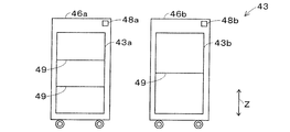
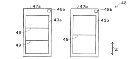
- the matters described about the guide portion 45 can be said in the same manner for the carriage 46 shown in FIG. 7B, and the same can be said for the form shown in FIGS. 7C and 7D.
- the guide unit 45 is a unit after the first unit production UJ0 in which the supply product 9S used for the next unit production UJ0 of the first unit production UJ1 is delivered and the first delivery unit 43a and the next unit production UJ0 of the first unit production UJ1. It is preferable to guide the supply product 9S used for the production UJ0 so that it can be distinguished from the first delivery unit 43a to which the supply product 9S is delivered.
- the guide unit 45 displays that the rest of the upper space of the shelf 47 shown in FIG. 7A is for the next production, but the rest of the upper space of the shelf 47 is for the next production. Indicates that it is for subsequent production.
- the worker can use the first delivery unit 43a from which the supply product 9S used for the next unit production UJ0 of the first unit production UJ1 is delivered and the unit after the next unit production UJ0 of the first unit production UJ1. It is possible to distinguish the supply product 9S used for the production UJ0 from the first delivery unit 43a to be delivered.
- a partition plate 49 may be provided between these first delivery portions 43a.
- the guide unit 45 has a second warehousing unit 43b to which the equipment 9F used for the next unit production UJ0 of the first unit production UJ1 is delivered, and a unit production after the next unit production UJ0 of the first unit production UJ1. It is preferable to guide the device 9F used for UJ0 so that it can be distinguished from the second delivery section 43b to which the device 9F is delivered.
- the guide unit 45 indicates that the rest of the lower space of the shelf 47 is for the next production. Indicates that it is for subsequent production.
- the worker can issue the second warehousing unit 43b from which the equipment 9F used for the next unit production UJ0 of the first unit production UJ1 is delivered, and the unit production after the next unit production UJ0 of the first unit production UJ1. It is possible to distinguish the device 9F used for UJ0 from the second delivery section 43b to which the device 9F is delivered.
- a partition plate 49 may be provided between these second delivery portions 43b.
- the worker can supply the supplied product 9S used in a predetermined production time zone (for example, production of the substrate product 900 in the morning) and a production time zone later than the production time zone (for example, production of the substrate product 900 in the afternoon).
- the guide unit 45 is the first warehousing unit 43a from which the supply product 9S used in the first production time zone TM1 is delivered and the first warehousing unit 43a from which the supply product 9S used in the second production time zone TM2 is delivered. It is advisable to guide the 43a so that it can be identified.
- the first production time zone TM1 at least one unit production UJ0 of the second unit production UJ2 is performed.
- at least one other unit production UJ0 of the second unit production UJ2 is performed later than the first production time zone TM1.
- the guide unit 45 displays that the rest of the upper space of the shelf 47 shown in FIG. 7A is for the next production, but the rest of the upper space of the shelf 47 is the production of the first production time zone TM1. Indicates that the product is for production and that it is for production in the second production time zone TM2.
- the worker can use the first warehousing unit 43a from which the supply product 9S used in the first production time zone TM1 is delivered and the first warehousing unit 43a from which the supply product 9S used in the second production time zone TM2 is delivered. It can be distinguished from 43a.
- a partition plate 49 may be provided between these first delivery portions 43a.
- the guide unit 45 includes a second warehousing unit 43b to which the device 9F used in the first production time zone TM1 is delivered and a second warehousing unit 43b to which the device 9F used in the second production time zone TM2 is delivered. It is good to guide you so that you can identify.
- the guide unit 45 displays that the rest of the lower space of the shelf 47 shown in FIG. 7A is for the next production, but the rest of the lower space of the shelf 47 is the production of the first production time zone TM1. Indicates that the product is for production and that it is for production in the second production time zone TM2.
- the worker can use the second warehousing section 43b from which the equipment 9F used in the first production time zone TM1 is delivered and the second warehousing section 43b from which the device 9F used in the second production time zone TM2 is delivered. Can be identified.
- a partition plate 49 may be provided between these second delivery portions 43b.
- the first delivery section 43a and the second delivery section 43b are formed on a shelf 47 capable of holding the supplied item 9S and the device 9F.
- the first warehousing section 43a and the second warehousing section 43b can be formed on a trolley 46 capable of holding the supplied item 9S and the device 9F.
- the carriage 46 has the same configuration as the shelf 47 described above.
- a transport vehicle similar to the transport vehicle 30 can be used, and it may be an automatic guided vehicle or may be towed by an operator.
- the first delivery section 43a and the second delivery section 43b can also be formed on a plurality of carriages 46 or a plurality of shelves 47. Further, a plurality of first warehousing portions 43a may be formed or a plurality of second warehousing portions 43b may be formed on one trolley 46 or one shelf 47. In either case, it is necessary to identify the first delivery unit 43a and the second delivery unit 43b. Therefore, it is preferable that the trolley 46 or the shelf 47 is provided with a first identification unit 48a for identifying the first delivery unit 43a and a second identification unit 48b for identifying the second delivery unit 43b.
- the first identification unit 48a may take various forms as long as it can identify the first delivery unit 43a.
- the second identification unit 48b may take various forms as long as it can identify the second delivery unit 43b.
- a one-dimensional code, a two-dimensional code, a wireless tag, or the like can be used for the first identification unit 48a and the second identification unit 48b.
- the first identification unit 48a and the second identification unit 48b may be guided by the guide unit 45.
- the first delivery section 43a is formed on the first carriage 46a capable of holding the supplied product 9S
- the second delivery section 43b is formed on the second carriage 46b capable of holding the device 9F. May be done.
- the first trolley 46a is provided with a first identification unit 48a for identifying the first warehousing unit 43a
- the second trolley 46b is provided with a second identification unit 48b for identifying the second warehousing unit 43b. It is good to have it.
- the first delivery section 43a is formed on the first shelf 47a capable of holding the supplied product 9S
- the second delivery section 43b is formed on the second shelf 47b capable of holding the device 9F. May be done.
- the first shelf 47a is provided with a first identification unit 48a for identifying the first delivery unit 43a
- the second shelf 47b is provided with a second identification unit 48b for identifying the second delivery unit 43b. It is good to have it.
- the storage 40 and the worker can identify the first delivery unit 43a and the second delivery unit 43b.
- the supply product 9S and the equipment 9F are associated and delivered through the second opening 41b.
- the storage 40 can also be delivered in association with the supply 9S and the equipment 9F through the first opening 41a.
- the moving unit 44 can use the moving device 40b to take out the storage case 93 containing the supply item 9S and the device 9F through the first opening 41a.
- a transport device can be provided outside the storage 40. In this case, the transport device transports the supplied product 9S delivered through the first opening 41a to the delivery section 43. The transport device transports the equipment 9F delivered through the first opening 41a to the delivery section 43.
- the transport device can transport the supplied product 9S delivered through the first opening 41a to the first delivery section 43a.
- the transport device can transport the device 9F delivered through the first opening 41a to the second delivery section 43b.
- the transport device can also transport the storage case 93 accommodating at least one of the supplied product 9S and the device 9F delivered through the first opening 41a to the delivery section 43.
- the warehousing section 43 is not limited to a form in which the warehousing section 43 is partitioned as a dedicated warehousing section, such as the first warehousing section 43a and the second warehousing section 43b.
- the warehousing section 43 may have, for example, a form in which a portion corresponding to the first warehousing section 43a and a portion corresponding to the second warehousing section 43b are mixed.
- the storage 40 may partition the delivery section 43 for each of the same unit production UJ0, and deliver the supply 9S and the equipment 9F used for the same unit production UJ0 to each section. Further, the delivery unit 43 may not deliver only the supply product 9S and the equipment 9F used for one unit production UJ0, and at the same time, the supply product 9S and the equipment 9F used for the other unit production UJ0 may not be delivered.
- the storage 40 includes a first storage 42a, a second storage 42b, a delivery 43, and a moving unit 44.
- the storage 40 can store the supplied product 9S in the first storage section 42a and the device 9F in the second storage section 42b.
- the moving unit 44 moves the supplied item 9S stored in the first storage unit 42a to the delivery unit 43, and moves the device 9F stored in the second storage unit 42b to the delivery unit 43.
- the delivery unit 43 can issue the supply 9S and the equipment 9F used for the predetermined unit production UJ0 in association with each other.
- 10 Board work machine, 10c: Parts mounting machine, 40: Storage, 42a: 1st storage section, 42b: 2nd storage section, 43: delivery section, 43a: First delivery section, 43b: Second delivery section, 44: Moving section, 45: Information section, 46: Bogie, 46a: First trolley, 46b: Second trolley, 47: Shelf, 47a: First shelf, 47b: Second shelf, 48a: First identification unit, 48b: Second identification unit, 90: Substrate, 91: Article, 93: Storage case, 95c: Holding member, 9S: Supply product, 9F: Equipment, 900: Substrate product, UJ0: Unit production, UJ1: First unit production, UJ2: Second unit production, TM1: First production time zone, TM2: Second production time zone.
Landscapes
- Engineering & Computer Science (AREA)
- Manufacturing & Machinery (AREA)
- Microelectronics & Electronic Packaging (AREA)
- Operations Research (AREA)
- Supply And Installment Of Electrical Components (AREA)
- General Factory Administration (AREA)
Abstract
保管庫は、第一収納部と、第二収納部と、出庫部と、移動部とを備える。第一収納部は、基板に所定の対基板作業を行う対基板作業機によって基板に設けられる物品、および、物品が設けられる前の基板のうちの少なくとも一方である供給品を収納する。第二収納部は、対基板作業機に着脱可能に設けられて対基板作業において用いられる機器を収納する。出庫部は、対基板作業機を用いた同一種類の基板製品の生産が指定される単位生産の順序が規定されている生産計画に含まれる所定の単位生産に用いられる供給品および機器を関連付けて出庫する。移動部は、第一収納部に収納されている供給品を出庫部に移動させ、第二収納部に収納されている機器を出庫部に移動させる。
Description
本明細書は、保管庫に関する技術を開示する。
特許文献1に記載の保管庫は、実装ヘッドおよびフィーダ装置を保管する。また、特許文献1に記載の交換支援装置は、生産する基板の種類を変更する段取り替えを行うときに、生産ジョブ情報とメンテナンス情報に基づいて、保管庫に保管されている実装ヘッドおよびフィーダ装置の中から、部品実装機に装備させる実装ヘッドおよびフィーダ装置を決定する。交換支援装置は、段取り替え後の生産で必要になる部品種のリールを保持しているフィーダ装置を探索する。さらに、交換支援装置の案内部は、保管庫から出庫させる実装ヘッドおよびフィーダ装置を作業者に案内する。
また、特許文献2に記載のノズル管理機は、セッティング制御部が、部品装着機および管理装置のうちの少なくとも一方から受信した情報に基づいて、部品装着機において必要とされる吸着ノズルをノズルトレイにセットする。
対基板作業機を用いた基板製品の生産には、対基板作業機によって基板に設けられる物品などの供給品と、対基板作業機に着脱可能に設けられて対基板作業において用いられる機器の両方が必要になる。また、生産する基板製品の種類が異なると、必要になる供給品および機器の組み合わせも変わるので、生産する基板製品の種類に合致した供給品と機器が必要である。さらに、上述したリールとフィーダ装置のように、供給品が機器に組み込まれた状態で保管されると、出庫する際の供給品および機器の組み合わせが限定される可能性がある。
このような事情に鑑みて、本明細書は、供給品および機器をそれぞれ保管することができ、同一種類の基板製品の生産が指定される単位生産に用いられる供給品と機器を関連付けて出庫可能な保管庫を開示する。
本明細書は、第一収納部と、第二収納部と、出庫部と、移動部とを備える保管庫を開示する。前記第一収納部は、基板に所定の対基板作業を行う対基板作業機によって前記基板に設けられる物品、および、前記物品が設けられる前の前記基板のうちの少なくとも一方である供給品を収納する。前記第二収納部は、前記対基板作業機に着脱可能に設けられて前記対基板作業において用いられる機器を収納する。前記出庫部は、前記対基板作業機を用いた同一種類の基板製品の生産が指定される単位生産の順序が規定されている生産計画に含まれる所定の前記単位生産に用いられる前記供給品および前記機器を関連付けて出庫する。前記移動部は、前記第一収納部に収納されている前記供給品を前記出庫部に移動させ、前記第二収納部に収納されている前記機器を前記出庫部に移動させる。
上記の保管庫によれば、第一収納部と、第二収納部と、出庫部と、移動部とを備える。これにより、上記の保管庫は、第一収納部に供給品を収納し、第二収納部に機器を収納することができる。また、上記の保管庫は、移動部が第一収納部に収納されている供給品を出庫部に移動させ、第二収納部に収納されている機器を出庫部に移動させて、出庫部が所定の単位生産に用いられる供給品および機器を関連付けて出庫することができる。
1.実施形態
図1に示すように、本実施形態の保管庫40は、基板生産設備80に設けられている。基板生産設備80は、対基板作業ライン10Lと、着荷部20と、搬送車30と、保管庫40とを備えている。
図1に示すように、本実施形態の保管庫40は、基板生産設備80に設けられている。基板生産設備80は、対基板作業ライン10Lと、着荷部20と、搬送車30と、保管庫40とを備えている。
1-1.対基板作業ライン10L
対基板作業ライン10Lでは、基板90に所定の対基板作業を行う。対基板作業ライン10Lを構成する対基板作業機10の種類および数は、限定されない。図1に示すように、本実施形態の対基板作業ライン10Lは、印刷機10a、印刷検査機10b、部品装着機10c、リフロー炉10dおよび外観検査機10eの複数(5つ)の対基板作業機10を備えており、基板90は、基板搬送装置によって、この順に搬送される。
対基板作業ライン10Lでは、基板90に所定の対基板作業を行う。対基板作業ライン10Lを構成する対基板作業機10の種類および数は、限定されない。図1に示すように、本実施形態の対基板作業ライン10Lは、印刷機10a、印刷検査機10b、部品装着機10c、リフロー炉10dおよび外観検査機10eの複数(5つ)の対基板作業機10を備えており、基板90は、基板搬送装置によって、この順に搬送される。
印刷機10aは、基板90の複数の部品の装着位置に、はんだを印刷する。基板90に印刷されるはんだは、所定の粘性を有し、はんだは、基板90と、基板90に装着される部品とを接合する接合材として機能する。図2に示すように、はんだは、はんだ収容容器91cに収容されている。はんだ収容容器91cは、例えば、有底筒状またはチューブ状の密閉可能な容器を用いることができる。
印刷検査機10bは、印刷機10aによって印刷されたはんだの印刷状態を検査する。部品装着機10cは、はんだが印刷された基板90に複数の部品を装着する。部品装着機10cは、一つであっても良く、複数であっても良い。部品装着機10cが複数設けられる場合は、複数の部品装着機10cが分担して、基板90に複数の部品を装着することができる。
部品装着機10cは、基板90に装着される部品を供給する部品供給装置を備えている。部品供給装置は、例えば、図2に示すリール91aを備えるフィーダ95b、トレイ91bなどを用いて部品を供給することができる。リール91aには、部品を収容する部品テープ(キャリアテープ)が巻回されている。リール91aは、フィーダ95bに回転可能かつ着脱可能に設けられ、部品テープの先端部がフィーダ95bに設けられる部品取出し部まで引き出されて、部品が順次供給される。リール91aは、例えば、チップ部品などの比較的小型の部品を供給することができる。
トレイ91bには、複数の部品が配列されている。トレイ91bは、例えば、QFP(Quad Flat Package)、BGA(Ball Grid Array)などの比較的大型の部品を供給することができる。また、部品供給装置は、例えば、部品収容容器91dに収容されている部品を供給することもできる。部品収容容器91dには、複数の部品が配列されることなく収容されている。
さらに、部品装着機10cには、装着ヘッド95aが着脱可能(交換可能)に設けられる。装着ヘッド95aは、少なくとも一つの保持部材95cが着脱可能(交換可能)に設けられる。保持部材95cは、例えば、吸着ノズル、チャックなどを用いることができる。部品装着機10cは、装着ヘッド95aおよび保持部材95cを用いて、部品供給装置によって供給される部品を採取し保持して、位置決めされた基板90に部品を装着する。
なお、保持部材95cは、基板90に部品を装着する装着処理において部品の種別に応じて適宜変更され得る。部品装着機10cは、例えば、実行する装着処理に用いる保持部材95cが装着ヘッド95aに取り付けられていない場合に、保持部材収容装置95dに収容されている保持部材95cを装着ヘッド95aに取り付けることができる。保持部材収容装置95dは、複数の保持部材95cを着脱可能(交換可能)に収容することができ、部品装着機10cの機内の所定位置に着脱可能(交換可能)に装備される。
リフロー炉10dは、部品装着機10cによって複数の部品が装着された基板90を加熱し、はんだを溶融させて、はんだ付けを行う。外観検査機10eは、部品装着機10cによって装着された複数の部品の装着状態などを検査する。このように、対基板作業ライン10Lは、複数(5つ)の対基板作業機10を用いて、基板90を順に搬送し、検査処理を含む生産処理を実行して基板製品900を生産することができる。なお、対基板作業ライン10Lは、例えば、機能検査機、バッファ装置、基板供給装置、基板反転装置、シールド装着装置、接着剤塗布装置、紫外線照射装置などの対基板作業機10を必要に応じて備えることもできる。
対基板作業ライン10Lを構成する複数(5つ)の対基板作業機10および管理装置19は、有線または無線の通信部によって、互いに通信可能に設けられている。管理装置19は、対基板作業ライン10Lを構成する複数(5つ)の対基板作業機10の制御を行い、対基板作業ライン10Lの動作状況を監視する。管理装置19には、複数(5つ)の対基板作業機10を制御する種々の制御データが記憶されている。管理装置19は、複数(5つ)の対基板作業機10の各々に制御データを送信する。また、複数(5つ)の対基板作業機10の各々は、管理装置19に動作状況および生産状況を送信する。
1-2.着荷部20および搬送車30
本明細書では、基板90に所定の対基板作業を行う対基板作業機10によって基板90に設けられる物品91、および、物品91が設けられる前の基板90のうちの少なくとも一方を供給品9Sという。また、対基板作業機10に着脱可能に設けられて対基板作業において用いられるものを機器9Fという。
本明細書では、基板90に所定の対基板作業を行う対基板作業機10によって基板90に設けられる物品91、および、物品91が設けられる前の基板90のうちの少なくとも一方を供給品9Sという。また、対基板作業機10に着脱可能に設けられて対基板作業において用いられるものを機器9Fという。
既述したように、対基板作業ライン10Lは、印刷機10aを備えている。この場合、例えば、はんだ収容容器91cに収容されているはんだは、物品91に相当する。また、例えば、スキージによって、はんだをマスクに沿って移動させて基板90に印刷処理を実行する印刷機10aの場合、スキージ、マスクは、機器9Fに相当する。さらに、例えば、印刷ヘッドによって、基板90の複数の印刷位置の各々に、はんだを塗布する印刷機の場合、印刷ヘッド、ディスペンスヘッドは、機器9Fに相当する。
また、対基板作業ライン10Lは、部品装着機10cを備えている。この場合、例えば、リール91aに巻回されている部品テープに収容されている部品は、物品91に相当する。トレイ91bに収容されている部品は、物品91に相当する。部品収容容器91dに収容されている部品は、物品91に相当する。また、部品装着機10cに着脱可能に設けられる装着ヘッド95aは、機器9Fに相当する。部品装着機10cに着脱可能に設けられるフィーダ95bは、機器9Fに相当する。装着ヘッド95aを介して部品装着機10cに着脱可能に設けられる保持部材95cは、機器9Fに相当する。部品装着機10cに着脱可能に設けられる保持部材収容装置95dは、機器9Fに相当する。
さらに、対基板作業ライン10Lは、印刷検査機10bを備えている。また、対基板作業ライン10Lは、外観検査機10eを備えている。これらの場合、例えば、検査対象(はんだ若しくは部品)を検査する検査ヘッドは、機器9Fに相当する。なお、図1に示す印刷機10aには、既述した物品91が設けられる前の基板90が搬送される。当該基板90は、供給品9Sに含まれる。
供給品9Sが着荷部20に到着すると、所定の着荷作業が行われる。そして、供給品9Sは、例えば、収容ケース93に収容されて搬送車30に搭載され、保管庫40に搬送される。供給品9Sは、保管庫40に保管された後、必要に応じて対基板作業ライン10Lに供給される。
図2に示すように、供給品9Sには、識別コード92が設けられる。識別コード92には、供給品9Sを識別する識別情報が記憶される。識別コード92は、例えば、一次元コード、二次元コード、無線タグなどを用いることができる。着荷部20に供給品9Sが到着すると、着荷部20の作業者は、例えば、管理装置を用いて、識別情報を発行する。また、作業者は、バーコードリーダなどを用いて、供給元(ベンダ)によって供給品9Sに設けられているバーコードなどを読み取る。そして、作業者は、供給品9Sに関する供給品情報が登録されているデータベースから、当該供給品9Sの供給品情報を取得することもできる。作業者は、管理装置を用いて、識別情報および供給品情報のうちの少なくとも識別情報を識別コード92に記憶させる。
着荷部20の作業者は、少なくとも識別情報が記憶されている識別コード92を供給品9Sに取り付けて、供給品9Sを収容ケース93に収容する。収容ケース93は、少なくとも一つの供給品9Sを収容することができれば良く、種々の形態をとり得る。また、収容ケース93には、特定コード94が設けられている。特定コード94には、収容ケース93を特定する特定情報が記憶されている。特定コード94は、例えば、一次元コード、二次元コード、無線タグなどを用いることができる。
作業者は、供給品9Sを収容ケース93に収容するときに、特定コード94を読み取り装置を用いて読み取り、当該供給品9Sに設けられている識別コード92を読み取り装置を用いて読み取る。これにより、供給品9Sを収容する収容ケース93を特定する特定情報と、当該供給品9Sを識別する識別情報との間の対応関係が生成され、対応関係が管理装置19の記憶部に送信され記憶される。供給品9Sについて上述されていることは、機器9Fが着荷部20に到着した場合についても同様に言える。
図2は、供給品9Sおよび機器9Fが収容ケース93に収容されている収容状態の一例を示す平面図である。具体的には、同図は、物品91に相当する部品を収容している部品テープが巻回されているリール91aが、収容ケース93に収容された状態の一例を示している。また、同図は、物品91に相当する部品を収容しているトレイ91bが収容ケース93に収容(積載)された状態の一例を示している。トレイ91bは、包装袋に収納されており、識別コード92は、トレイ91bの包装袋に取り付けられている。さらに、同図は、物品91に相当するはんだを収容しているはんだ収容容器91cが収容ケース93に収容された状態の一例を示している。また、同図は、物品91が設けられる前の基板90が収容ケース93に収容された状態の一例を示している。
さらに、同図は、機器9Fに相当する装着ヘッド95a、フィーダ95b、保持部材95cおよび保持部材収容装置95dが収容ケース93に収容された状態の一例を示している。装着ヘッド95aおよびフィーダ95bは、収容ケース93にそれぞれ収容されている。保持部材95cは、保持部材95cを着脱可能に収容する収容スペースに収容することができ、保持部材収容装置95dに着脱可能に収容することもできる。
なお、収容ケース93は、供給品9Sと機器9Fを一緒に収容することもできる。例えば、同図に示す収容ケース93には、物品91に相当する部品を収容している部品収容容器91dと、機器9Fに相当する保持部材95cおよび保持部材収容装置95dとが一緒に収容されている。また、いずれの場合も、収容ケース93には、緩衝材が設けられており、搬送時などに供給品9Sおよび機器9Fに印加される振動などが軽減されている。
着荷部20の作業者は、供給品9Sおよび機器9Fのうちの少なくとも一方が収容された収容ケース93を搬送車30に搭載する。搬送車30は、例えば、作業者が牽引することができる。また、搬送車30は、例えば、作業者による牽引が不要な自動走行可能な無人搬送車(AGV:Automatic Guided Vehicle)を用いることもできる。本実施形態の搬送車30は、無人搬送車である。
対基板作業ライン10L、着荷部20、搬送車30および保管庫40は、有線または無線の通信部によって、互いに通信可能に設けられている。供給品9Sおよび機器9Fのうちの少なくとも一方が収容された収容ケース93が搬送車30に搭載されると、管理装置19は、搬送車30に搬送指令を送信する。搬送指令には、収容ケース93の搬送先が含まれる。管理装置19は、当該収容ケース93を収納可能な保管庫40を選定して搬送先を決定する。搬送車30は、搬送指令を受信すると、搬送先に指定された保管庫40に収容ケース93を搬送する。
なお、搬送車30は、収容ケース93を用いることなく、供給品9Sおよび機器9Fのうちの少なくとも一方を搬送することもできる。また、搬送車30を用いることなく、作業者は、供給品9Sおよび機器9Fのうちの少なくとも一方を搬送することもできる。さらに、上述した作業者が行う作業の少なくとも一部は、搬送装置(例えば、ベルトコンベアなど)、アクチュエータ(例えば、ロボットアームなど)、管理装置などを用いて自動化することもできる。
1-3.保管庫40
このようにして、着荷部20に到着した供給品9Sおよび機器9Fのうちの少なくとも一方は、保管庫40に搬送される。また、対基板作業ライン10Lで不要になった供給品9Sおよび機器9Fのうちの少なくとも一方は、保管庫40に搬送される。保管庫40に搬送された供給品9Sおよび機器9Fは、保管庫40に保管され、必要に応じて対基板作業ライン10Lに搬送される。
このようにして、着荷部20に到着した供給品9Sおよび機器9Fのうちの少なくとも一方は、保管庫40に搬送される。また、対基板作業ライン10Lで不要になった供給品9Sおよび機器9Fのうちの少なくとも一方は、保管庫40に搬送される。保管庫40に搬送された供給品9Sおよび機器9Fは、保管庫40に保管され、必要に応じて対基板作業ライン10Lに搬送される。
保管庫40は、供給品9Sおよび機器9Fを保管することができれば良く、種々の形態をとり得る。図3Aおよび図3Bに示すように、本実施形態の保管庫40は、例えば、八角柱形状に形成されている。また、図3A~図3Cに示すように、保管庫40は、第一開口部41aと、第二開口部41bと、収納部42と、出庫部43と、制御装置40aと、移動装置40bとを備えている。収納部42は、第一収納部42aと、第二収納部42bとを備えており、第三収納部42cをさらに備えることもできる。出庫部43は、第一出庫部43aと、第二出庫部43bとを備えている。出庫部43は、例えば、台車46または棚47に形成することができる。
さらに、図4に示すように、制御装置40aは、制御ブロックとして捉えると、移動部44を備えている。制御装置40aは、案内部45をさらに備えることができる。また、保管庫40は、作業スペース40c、取得装置40d、表示装置40eおよび出庫スペース40fのうちの少なくとも一つを備えることができる。図3A~図3Cおよび図4に示すように、本実施形態の保管庫40は、上述した部位および装置をすべて備えている。また、出庫部43は、棚47に形成されている。
1-3-1.保管庫40の概略構成
図3Aおよび図3Bに示すように、保管庫40の正面には、第一開口部41aが設けられ、保管庫40の側面には、第二開口部41bが設けられている。第一開口部41aは、供給品9Sおよび機器9Fが入庫または出庫する。第一開口部41aは、供給品9Sおよび機器9Fが入庫可能または出庫可能に供給品9Sおよび機器9Fより大形に形成されている。
図3Aおよび図3Bに示すように、保管庫40の正面には、第一開口部41aが設けられ、保管庫40の側面には、第二開口部41bが設けられている。第一開口部41aは、供給品9Sおよび機器9Fが入庫または出庫する。第一開口部41aは、供給品9Sおよび機器9Fが入庫可能または出庫可能に供給品9Sおよび機器9Fより大形に形成されている。
なお、供給品9Sおよび機器9Fのうちの少なくとも一方は、収容ケース93に収容された状態で、第一開口部41aを介して入庫または出庫することもできる。この場合、第一開口部41aは、収容ケース93が入庫可能または出庫可能に収容ケース93より大形に形成される。第二開口部41bは、供給品9Sおよび機器9Fが出庫する。第一開口部41aについて上述されていることは、第二開口部41bについても同様に言える。
また、第一開口部41aには、取得装置40dが設けられている。取得装置40dは、供給品9Sに設けられる識別コード92を読み取って供給品9Sを識別する識別情報を取得する。同様に、取得装置40dは、機器9Fに設けられる識別コード92を読み取って機器9Fを識別する識別情報を取得する。取得装置40dは、公知の読み取り装置(例えば、一次元コード、二次元コードを読み取るコードリーダ、無線タグと無線通信を行う無線リーダなど)を用いることができる。
図3Aおよび図3Bに示すように、取得装置40dは、第一開口部41aの近傍に設けられる作業スペース40cの上方に設置されている。取得装置40dは、第一開口部41aを介して供給品9Sが入庫したときに、供給品9Sに設けられる識別コード92を読み取って、識別情報および供給品情報のうちの少なくとも識別情報を取得する。同様に、取得装置40dは、第一開口部41aを介して機器9Fが入庫したときに、機器9Fに設けられる識別コード92を読み取って、識別情報および機器9Fに関する機器情報のうちの少なくとも識別情報を取得する。
なお、取得装置40dは、第一開口部41aを介して収容ケース93が入庫したときに、収容ケース93に設けられる特定コード94を読み取って、特定情報を取得することもできる。この場合、取得装置40dは、特定情報と識別情報との間の対応関係に基づいて、収容ケース93に収容されている供給品9Sおよび機器9Fのうちの少なくとも一方の識別情報を取得することができる。
このように、本実施形態の保管庫40は、取得装置40dが第一開口部41aのみに設けられている。また、第一開口部41aは、供給品9Sおよび機器9Fが入庫可能または出庫可能な入出庫兼用口であり、第二開口部41bは、供給品9Sおよび機器9Fが出庫可能な出庫専用口である。
収納部42は、供給品9Sおよび機器9Fの両方を収納可能であれば良く、種々の形態をとり得る。図3Bに示すように、本実施形態の収納部42は、鉛直方向(Z軸方向)視において円状に配置されている。また、図3Cに示すように、収納部42は、供給品9Sを収納する第一収納部42aと、機器9Fを収納する第二収納部42bとを備えている。
なお、第一収納部42aおよび第二収納部42bの数および配置は、適宜変更することができる。例えば、複数の収納部42のうちの少なくとも一つの収納部42が第一収納部42aのみを備え、複数の収納部42のうちの他の少なくとも一つの収納部42が第二収納部42bのみを備えることもできる。また、図3Bに示すように、本実施形態の保管庫40は、第一収納部42aまたは第二収納部42bの一部が廃止されており、作業スペース40cおよび出庫スペース40fが確保されている。
さらに、第一収納部42aは、収納する供給品9Sに合わせて形状およびサイズ(幅、奥行き、および、高さ)を設定することができ、第二収納部42bは、収納する機器9Fに合わせて形状およびサイズ(幅、奥行き、および、高さ)を設定することができる。また、収納部42は、供給品9Sおよび機器9Fのうちの少なくとも一方を収容している収容ケース93を収納することもできる。
この場合、第一収納部42aおよび第二収納部42bは、収容ケース93に合わせて形状およびサイズ(幅、奥行き、および、高さ)を設定することができる。逆に、第一収納部42aおよび第二収納部42bの形状およびサイズ(幅、奥行き、および、高さ)に合わせて収容ケース93の形状およびサイズ(幅、奥行き、および、高さ)を設定することもできる。
また、図3Cに示すように、収納部42は、供給品9Sおよび機器9Fの両方を収納する第三収納部42cを備えることもできる。供給品9Sおよび機器9Fの両方を収容している(機器9Fと供給品9Sとが一緒に収容されている)収容ケース93は、第三収納部42cに収納される。さらに、供給品9S、機器9Fおよび収容ケース93は、適合する収納部42に収納することもできる。この場合、供給品9Sが収納される収納部42は、第一収納部42aである。機器9Fが収納される収納部42は、第二収納部42bである。供給品9Sおよび機器9Fの両方が収納される収納部42は、第三収納部42cである。また、基板生産設備80が複数の保管庫40を備える場合、適合する収納部42を備える保管庫40であれば、いずれの保管庫40に保管しても良い。
生産計画には、対基板作業機10を用いた同一種類の基板製品900の生産が指定される単位生産UJ0の順序が規定されている。例えば、生産計画には、第一種の基板製品900の生産、第二種の基板製品900の生産、第三種の基板製品900の生産などの順に、複数種類(例えば、三種類)の基板製品900を生産することが規定されている。また、生産計画には、生産する基板製品900の生産数、生産時期、納期、使用する供給品9Sおよび機器9Fなどを含むこともできる。さらに、生産可能な対基板作業ライン10Lが複数存在する場合、生産計画には、使用する対基板作業ライン10Lを含むこともできる。なお、生産計画は、一種類の基板製品900の生産計画であっても良い。
出庫部43は、生産計画に含まれる所定の単位生産UJ0に用いられる供給品9Sおよび機器9Fを関連付けて出庫する。本実施形態の出庫部43は、第一出庫部43aと、第二出庫部43bとを備えている。第一出庫部43aには、単位生産UJ0に用いられる供給品9Sが出庫される。第二出庫部43bには、第一出庫部43aから出庫される供給品9Sと同一の単位生産UJ0に用いられる機器9Fが出庫される。
第一出庫部43aおよび第二出庫部43bは、例えば、供給品9Sおよび機器9Fを保持可能な台車46または棚47に形成することができる。台車46または棚47は、供給品9Sおよび機器9Fを保持可能であれば良く、種々の形態をとり得る。図3Aに示すように、本実施形態では、第一出庫部43aおよび第二出庫部43bは、複数の収容スペースを備える棚47に形成されている。
例えば、棚47の上段スペースには、第一出庫部43aが形成され、棚47の下段スペースには、第二出庫部43bが形成されている。また、図3Bに示す第二開口部41bには、扉部が設けられている。棚47の上段スペースおよび下段スペースと出庫スペース40fは、第二開口部41bを介して連通可能になっている。具体的には、供給品9Sおよび機器9Fの出庫時に、制御装置40aによって扉部が開状態に制御される。そして、第二開口部41bを介して、同一の単位生産UJ0に用いられる供給品9Sおよび機器9Fが関連付けられて出庫される。供給品9Sおよび機器9Fが出庫されると、制御装置40aによって扉部は閉状態に制御される。
制御装置40aは、公知の演算装置および記憶装置を備えており、制御回路が構成されている。制御装置40aは、移動装置40b、取得装置40dおよび表示装置40eと通信可能に設けられており、これらを制御することができる。また、制御装置40aは、第一開口部41aおよび第二開口部41bにそれぞれ設けられる扉部を開閉制御することもできる。さらに、制御装置40aは、供給品9Sに関する供給品情報を記憶することができ、当該供給品情報を管理装置19に通知することもできる。
例えば、供給品9Sがリール91aの場合、供給品情報は、リール91aに収容されている部品の部品種、部品数(残数)、リール径、型式および供給元(ベンダ)、使用期限などを含むことができる。同様に、制御装置40aは、機器9Fに関する機器情報を記憶することができ、当該機器情報を管理装置19に通知することもできる。例えば、機器9Fが装着ヘッド95aの場合、機器情報は、装着ヘッド95aの使用回数、使用時間、使用された部品装着機10c、メンテナンス時期などを含むことができる。
移動装置40bは、第一開口部41aを介して供給品9Sが入庫したときに所定の第一収納部42aに供給品9Sを移動し、供給品9Sを出庫するときに第一収納部42aに収納されている供給品9Sを出庫スペース40fに移動する。同様に、移動装置40bは、第一開口部41aを介して機器9Fが入庫したときに所定の第二収納部42bに機器9Fを移動し、機器9Fを出庫するときに第二収納部42bに収納されている機器9Fを出庫スペース40fに移動する。
第一開口部41aを介して供給品9Sおよび機器9Fのうちの少なくとも一方が収容された収容ケース93が入庫した場合も同様である。つまり、移動装置40bは、第一開口部41aを介して収容ケース93が入庫したときに所定の第一収納部42a、第二収納部42bまたは第三収納部42cに収容ケース93を移動する。また、移動装置40bは、収容ケース93を出庫するときに第一収納部42a、第二収納部42bまたは第三収納部42cに収納されている収容ケース93を出庫スペース40fに移動する。
図3Bに示すように、本実施形態の移動装置40bは、鉛直方向(Z軸方向)視において、収納部42より内側に設けられている。移動装置40bは、対象物(供給品9Sおよび機器9Fまたは収容ケース93)を移動することができれば良く、種々の形態をとり得る。移動装置40bは、例えば、ロボットアーム(多関節ロボット)、昇降スライド機構などを用いることができる。
移動装置40bは、例えば、昇降部40b1と把持部40b2を備えることができる。昇降部40b1は、鉛直方向(Z軸方向)に沿った軸線回りに回転することができ、鉛直方向(Z軸方向)に沿って把持部40b2を昇降することができる。把持部40b2は、前進または後退することができ、対象物を保持または解放することができる。これにより、移動装置40bは、第一開口部41aを介して入庫した対象物を収納部42に収納することができ、対象物を出庫スペース40fに移動することができる。また、移動装置40bは、出庫スペース40fに移動した対象物を出庫部43に移動することもできる。さらに、移動装置40bは、出庫スペース40fに搬送装置(例えば、ベルトコンベアなど)を備えることもできる。この場合、搬送装置は、出庫スペース40fに移動した対象物を出庫部43に移動することができる。
なお、移動装置40bは、供給品9Sを出庫するときに、第一収納部42aに収納されている供給品9Sを第一開口部41aに設けられる作業スペース40cに移動することもできる。同様に、移動装置40bは、機器9Fを出庫するときに、第二収納部42bに収納されている機器9Fを第一開口部41aに設けられる作業スペース40cに移動することもできる。また、移動装置40bは、供給品9Sおよび機器9Fの両方を出庫するときに、第三収納部42cに収納されている供給品9Sおよび機器9Fを第一開口部41aに設けられる作業スペース40cに移動することもできる。上述したことは、供給品9Sおよび機器9Fのうちの少なくとも一方が収容ケース93に収容されている場合についても同様に言える。
本実施形態の保管庫40では、供給品9Sおよび機器9Fのうちの少なくとも一方は、収容ケース93に収容された状態で保管され、収容ケース93に収容された状態で出庫される。そのため、収容ケース93に収容された供給品9Sおよび機器9Fのうちの少なくとも一方の移動が容易であり、供給品9Sおよび機器9Fの種類に関わらず、移動装置40bの把持部40b2を共通化し易い。また、供給品9Sおよび機器9Fのうちの少なくとも一方を収容ケース93に収容した状態で保管し出庫することで、供給品9Sおよび機器9Fのうちの少なくとも一方の管理が容易になり、紛失等を軽減することもできる。
既述したように、収容ケース93は、種々の供給品9Sを収容することができ、種々の機器9Fを収容することができる。また、収容ケース93は、供給品9Sおよび機器9Fの両方を収容する(機器9Fと供給品9Sを一緒に収容する)こともできる。例えば、対基板作業機10が、供給品9Sである部品を供給品9Sである基板90に装着する部品装着機10cの場合を想定する。この場合、例えば、部品種によっては保持可能な保持部材95cが限定される場合があり、部品と当該部品を保持可能な保持部材95cとを一緒に管理することが好ましい場合がある。この場合、収容ケース93には、部品を採取し保持して基板90に装着する機器9Fである保持部材95cと、保持部材95cによって保持可能な部品とが一緒に収容されていると良い。このように、供給品9Sおよび機器9Fの関連度(関連付けの度合)が高くなるほど、機器9Fと供給品9Sとを一緒に収容ケース93に収容すると良い。
図3Aに示すように、保管庫40は、表示装置40eを備えている。表示装置40eは、公知の表示装置を用いることができ、各種データを作業者が視認可能に表示する。表示装置40eは、例えば、第一収納部42aに収納されている供給品9Sに関する供給品情報、第二収納部42bに収納されている機器9Fに関する機器情報などを作業者の操作に応じて表示する。
また、制御装置40aは、収納部42における供給品9Sおよび機器9Fの位置情報、入出庫情報および保管情報を記憶することができ、表示装置40eは、これらの情報を表示することもできる。位置情報は、供給品9Sおよび機器9Fの収納場所を示す。入出庫情報は、供給品9Sおよび機器9Fの入庫日時および出庫日時を示す。保管情報には、例えば、収納部42の雰囲気温度、収納部42の湿度などの情報が含まれる。制御装置40aは、供給品9Sおよび機器9Fの収納時に供給品9Sおよび機器9Fの位置情報および入庫日時を記憶する。制御装置40aは、供給品9Sおよび機器9Fの保管中に保管情報を記憶する。制御装置40aは、供給品9Sおよび機器9Fの出庫時に供給品9Sおよび機器9Fの出庫日時を記憶する。
なお、本実施形態の表示装置40eは、タッチパネルによって構成されており、表示装置40eは、作業者による種々の操作を受け付ける入力装置としても機能する。例えば、作業者は、タッチパネル(入力装置として機能する表示装置40e)を用いて、保管庫40から出庫させる所望の供給品9Sおよび機器9Fを指定することもできる。この場合、保管庫40は、指定された供給品9Sおよび機器9Fを出庫する。
1-3-2.供給品9Sおよび機器9Fの入出庫の制御例
図4に示すように、制御装置40aは、制御ブロックとして捉えると、移動部44および案内部45を備えている。また、制御装置40aは、図5Aおよび図5Bに示すフローチャートに従って、制御プログラムを実行する。
図4に示すように、制御装置40aは、制御ブロックとして捉えると、移動部44および案内部45を備えている。また、制御装置40aは、図5Aおよび図5Bに示すフローチャートに従って、制御プログラムを実行する。
図5Aは、供給品9Sおよび機器9Fの入庫作業における制御手順の一例を示している。制御装置40aは、第一開口部41aを介して供給品9Sが入庫したときに、取得装置40dを用いて、供給品9Sの識別情報を取得する(ステップS11)。同様に、制御装置40aは、第一開口部41aを介して機器9Fが入庫したときに、取得装置40dを用いて、機器9Fの識別情報を取得することもできる。
また、制御装置40aは、第一開口部41aを介して収容ケース93が入庫したときに、取得装置40dを用いて、収容ケース93の特定情報を取得することもできる。この場合、制御装置40aは、特定情報と識別情報との間の対応関係に基づいて、収容ケース93に収容されている供給品9Sおよび機器9Fのうちの少なくとも一方の識別情報を取得する。いずれの場合も、制御装置40aは、取得した識別情報を記憶装置に記憶させる。
次に、移動部44は、移動装置40bを用いて、所定の第一収納部42aに供給品9Sを移動させて収納させる(ステップS12)。同様に、移動部44は、移動装置40bを用いて、所定の第二収納部42bに機器9Fを移動させて収納させることもできる。また、移動部44は、移動装置40bを用いて、所定の第三収納部42cに供給品9Sおよび機器9Fを移動させて収納させることもできる。さらに、移動部44は、移動装置40bを用いて、所定の収納部42に収容ケース93を移動させて収納させることもできる。いずれの場合も、制御装置40aは、供給品9Sおよび機器9Fの位置情報および入庫日時を記憶装置に記憶させる。
次に、制御装置40aは、入庫予定のすべての供給品9Sおよび機器9Fが入庫したか否かを判断する(ステップS13)。入庫予定のすべての供給品9Sおよび機器9Fが入庫した場合(ステップS13でYesの場合)、入庫作業における制御は、一旦、終了する。入庫予定のすべての供給品9Sおよび機器9Fが入庫していない場合(ステップS13でNoの場合)、入庫作業における制御は、ステップS11に示す処理に戻る。そして、入庫予定のすべての供給品9Sおよび機器9Fが入庫されるまで、ステップS11~ステップS13に示す処理および判断が繰り返される。
図5Bは、供給品9Sおよび機器9Fの出庫作業における制御手順の一例を示している。生産計画は、例えば、管理装置19によって管理されており、管理装置19は、生産計画に基づいて、保管庫40に対して同一の単位生産UJ0に用いられる供給品9Sおよび機器9Fの出庫指令を送信する。保管庫40は、出庫指令を受信すると、指定された同一の単位生産UJ0に用いられる供給品9Sおよび機器9Fを関連付けて出庫する。
具体的には、移動部44は、第一収納部42aに収納されている供給品9Sを出庫部43に移動させ、第二収納部42bに収納されている機器9Fを出庫部43に移動させる。また、移動部44は、第一収納部42aに収納されている供給品9Sを第一出庫部43aに移動させ、第二収納部42bに収納されている機器9Fを第二出庫部43bに移動させることもできる。本実施形態では、移動部44は、移動装置40bを用いて、第一収納部42aに収納されている供給品9Sを出庫スペース40fに移動し、出庫スペース40fに移動した供給品9Sを第一出庫部43aに移動する。
また、移動部44は、移動装置40bを用いて、第二収納部42bに収納されている機器9Fを出庫スペース40fに移動し、出庫スペース40fに移動した機器9Fを第二出庫部43bに移動する(ステップS21)。移動部44は、移動装置40bを用いて、収納部42に収納されている収容ケース93を出庫スペース40fに移動し、出庫スペース40fに移動した収容ケース93を出庫部43に移動することもできる。いずれの場合も、制御装置40aは、供給品9Sおよび機器9Fの出庫日時を記憶装置に記憶させる。
次に、制御装置40aは、出庫予定のすべての供給品9Sおよび機器9Fが出庫したか否かを判断する(ステップS22)。出庫予定のすべての供給品9Sおよび機器9Fが出庫した場合(ステップS22でYesの場合)、出庫作業における制御は、一旦、終了する。出庫予定のすべての供給品9Sおよび機器9Fが出庫していない場合(ステップS22でNoの場合)、出庫作業における制御は、ステップS21に示す処理に戻る。そして、出庫予定のすべての供給品9Sおよび機器9Fが出庫されるまで、ステップS21およびステップS22に示す処理および判断が繰り返される。
ここで、対基板作業機10によって基板製品900の生産が行われている一の単位生産UJ0を第一単位生産UJ1とする。また、図6に示すように、第一単位生産UJ1より後の少なくとも一つの単位生産UJ0を第二単位生産UJ2とする。第一単位生産UJ1では、対基板作業機10によって基板製品900の生産が行われているので、機器9Fは、既に対基板作業機10に装備されている。そのため、第一単位生産UJ1における機器9Fの出庫要請は、第二単位生産UJ2と比べて少ない。
そこで、出庫部43が供給品9Sおよび機器9Fを関連付けて出庫する形態として、第二単位生産UJ2に用いられる供給品9Sおよび機器9Fを出庫する場合が想定される。この場合、移動部44は、第二単位生産UJ2に用いられる供給品9Sおよび機器9Fを移動させることができる。具体的には、移動部44は、管理装置19から受信した出庫指令に基づいて、移動装置40bを用いて、第二単位生産UJ2に用いられる供給品9Sおよび機器9Fを移動する。
また、本実施形態の保管庫40は、案内部45を備えている。案内部45は、第二単位生産UJ2に用いられる供給品9Sが出庫される第一出庫部43aと、第二単位生産UJ2に用いられる機器9Fが出庫される第二出庫部43bとを作業者に案内する。これにより、作業者は、第二単位生産UJ2に用いられる供給品9Sおよび機器9Fを認識し易くなる。
案内部45は、上記の第一出庫部43aおよび第二出庫部43bを作業者に案内することができれば良く、種々の形態をとり得る。例えば、案内部45は、図3Aに示す表示装置40eを用いて、棚47に形成されている上記の第一出庫部43aおよび第二出庫部43bの位置を表示することができる。また、図7Aに示すように、案内部45は、棚47に表示装置を設けて、当該表示装置を用いて、棚47に形成されている上記の第一出庫部43aおよび第二出庫部43bの位置を表示することもできる。
具体的には、案内部45は、棚47の上段スペースの近傍に供給品9Sの出庫場所であることを表示して、棚47の上段スペースに上記の第一出庫部43aが形成されていることを案内する。同様に、棚47の下段スペースの近傍に機器9Fの出庫場所であることを表示して、棚47の下段スペースに上記の第二出庫部43bが形成されていることを案内する。
また、第一単位生産UJ1では、対基板作業機10によって基板製品900の生産が行われているので、例えば、リール91aに収容されている部品の不足(供給品9Sの不足)が発生する可能性がある。供給品9Sの不足が発生した場合、若しくは、供給品9Sの不足が発生する可能性がある場合、管理装置19は、保管庫40に当該供給品9Sの出庫指令を送信する。保管庫40は、出庫指令を受信すると、当該供給品9Sを出庫する。
この場合、移動部44は、第一単位生産UJ1に用いられる供給品9Sを第一出庫部43aに移動させる。具体的には、移動部44は、管理装置19から受信した出庫指令に基づいて、移動装置40bを用いて、第一単位生産UJ1に用いられる供給品9Sを第一出庫部43aに移動する。この場合、案内部45は、第一単位生産UJ1に用いられる供給品9Sが出庫される第一出庫部43aと、第二単位生産UJ2に用いられる供給品9Sが出庫される第一出庫部43aとを識別可能に案内すると良い。
具体的には、案内部45は、図7Aに示す棚47の上段スペースの一部が現在の生産用であることを表示して、当該スペースに第一単位生産UJ1に用いられる供給品9Sが出庫されることを案内することができる。また、案内部45は、図7Aに示す棚47の上段スペースの残りが次の生産用であることを表示して、当該スペースに第二単位生産UJ2に用いられる供給品9Sが出庫されることを案内することができる。これにより、作業者は、第一単位生産UJ1に用いられる供給品9Sが出庫される第一出庫部43aと、第二単位生産UJ2に用いられる供給品9Sが出庫される第一出庫部43aとを識別することができる。
なお、既述したように、第一単位生産UJ1における機器9Fの出庫要請は、第二単位生産UJ2と比べて少ないが、例えば、機器9Fのトラブルなどによって、第一単位生産UJ1において新たな機器9Fが必要になる可能性もある。そのため、供給品9Sの場合と同様にして、移動部44は、第一単位生産UJ1に用いられる機器9Fを第二出庫部43bに移動させることもできる。この場合、案内部45は、第一単位生産UJ1に用いられる機器9Fが出庫される第二出庫部43bと、第二単位生産UJ2に用いられる機器9Fが出庫される第二出庫部43bとを識別可能に案内すると良い。
具体的には、案内部45は、図7Aに示す棚47の下段スペースの一部が現在の生産用であることを表示して、当該スペースに第一単位生産UJ1に用いられる機器9Fが出庫されることを案内することができる。また、案内部45は、図7Aに示す棚47の下段スペースの残りが次の生産用であることを表示して、当該スペースに第二単位生産UJ2に用いられる機器9Fが出庫されることを案内することができる。これにより、作業者は、第一単位生産UJ1に用いられる機器9Fが出庫される第二出庫部43bと、第二単位生産UJ2に用いられる機器9Fが出庫される第二出庫部43bとを識別することができる。
また、棚47には、仕切り板49を設けることができる。図7Aに示す第一出庫部43aに設けられる仕切り板49は、第一単位生産UJ1に用いられる供給品9Sが出庫される第一出庫部43aと、第二単位生産UJ2に用いられる供給品9Sが出庫される第一出庫部43aとを区分している。また、第二出庫部43bに設けられる仕切り板49は、第一単位生産UJ1に用いられる機器9Fが出庫される第二出庫部43bと、第二単位生産UJ2に用いられる機器9Fが出庫される第二出庫部43bとを区分している。案内部45について記述されている事項は、図7Bに示す台車46についても同様に言え、図7Cおよび図7Dに示す形態についても同様に言える。
作業者は、直近の単位生産UJ0に用いられる供給品9Sと、当該単位生産UJ0より後の単位生産UJ0に用いられる供給品9Sとを識別することが困難な場合がある。そこで、案内部45は、第一単位生産UJ1の次の単位生産UJ0に用いられる供給品9Sが出庫される第一出庫部43aと、第一単位生産UJ1の次の単位生産UJ0より後の単位生産UJ0に用いられる供給品9Sが出庫される第一出庫部43aとを識別可能に案内すると良い。
具体的には、案内部45は、図7Aに示す棚47の上段スペースの残りが次の生産用であることを表示する代わりに、棚47の上段スペースの残りが次の生産用と、それ以降の生産用であることを表示する。これにより、作業者は、第一単位生産UJ1の次の単位生産UJ0に用いられる供給品9Sが出庫される第一出庫部43aと、第一単位生産UJ1の次の単位生産UJ0より後の単位生産UJ0に用いられる供給品9Sが出庫される第一出庫部43aとを識別することができる。なお、これらの第一出庫部43aの間に仕切り板49を設けることもできる。
供給品9Sについて上述されていることは、機器9Fについても同様に言える。そこで、案内部45は、第一単位生産UJ1の次の単位生産UJ0に用いられる機器9Fが出庫される第二出庫部43bと、第一単位生産UJ1の次の単位生産UJ0より後の単位生産UJ0に用いられる機器9Fが出庫される第二出庫部43bとを識別可能に案内すると良い。
具体的には、案内部45は、図7Aに示す棚47の下段スペースの残りが次の生産用であることを表示する代わりに、棚47の下段スペースの残りが次の生産用と、それ以降の生産用であることを表示する。これにより、作業者は、第一単位生産UJ1の次の単位生産UJ0に用いられる機器9Fが出庫される第二出庫部43bと、第一単位生産UJ1の次の単位生産UJ0より後の単位生産UJ0に用いられる機器9Fが出庫される第二出庫部43bとを識別することができる。なお、これらの第二出庫部43bの間に仕切り板49を設けることもできる。
また、作業者は、所定の生産時間帯(例えば、午前の基板製品900の生産)に用いられる供給品9Sと、当該生産時間帯より遅い生産時間帯(例えば、午後の基板製品900の生産)に用いられる供給品9Sとを識別したい場合がある。そこで、案内部45は、第一生産時間帯TM1に用いられる供給品9Sが出庫される第一出庫部43aと、第二生産時間帯TM2に用いられる供給品9Sが出庫される第一出庫部43aとを識別可能に案内すると良い。第一生産時間帯TM1は、第二単位生産UJ2のうちの少なくとも一つの単位生産UJ0が行われる。図6に示すように、第二生産時間帯TM2は、第一生産時間帯TM1より遅く第二単位生産UJ2のうちの他の少なくとも一つの単位生産UJ0が行われる。
この形態では、案内部45は、図7Aに示す棚47の上段スペースの残りが次の生産用であることを表示する代わりに、棚47の上段スペースの残りが第一生産時間帯TM1の生産用と、第二生産時間帯TM2の生産用であることを表示する。これにより、作業者は、第一生産時間帯TM1に用いられる供給品9Sが出庫される第一出庫部43aと、第二生産時間帯TM2に用いられる供給品9Sが出庫される第一出庫部43aとを識別することができる。なお、これらの第一出庫部43aの間に仕切り板49を設けることもできる。
供給品9Sについて上述されていることは、機器9Fについても同様に言える。そこで、案内部45は、第一生産時間帯TM1に用いられる機器9Fが出庫される第二出庫部43bと、第二生産時間帯TM2に用いられる機器9Fが出庫される第二出庫部43bとを識別可能に案内すると良い。
この形態では、案内部45は、図7Aに示す棚47の下段スペースの残りが次の生産用であることを表示する代わりに、棚47の下段スペースの残りが第一生産時間帯TM1の生産用と、第二生産時間帯TM2の生産用であることを表示する。これにより、作業者は、第一生産時間帯TM1に用いられる機器9Fが出庫される第二出庫部43bと、第二生産時間帯TM2に用いられる機器9Fが出庫される第二出庫部43bとを識別することができる。なお、これらの第二出庫部43bの間に仕切り板49を設けることもできる。
本実施形態では、第一出庫部43aおよび第二出庫部43bは、供給品9Sおよび機器9Fを保持可能な棚47に形成されている。例えば、第一出庫部43aおよび第二出庫部43bは、供給品9Sおよび機器9Fを保持可能な台車46に形成することもできる。図7Bに示すように、台車46は、既述した棚47と同様の構成を備えている。また、台車46は、例えば、搬送車30と同様の搬送車を用いることができ、無人搬送車であっても良く、作業者によって牽引されても良い。
第一出庫部43aおよび第二出庫部43bは、複数の台車46または複数の棚47に形成することもできる。また、一つの台車46または一つの棚47において、複数の第一出庫部43aが形成されても良く、複数の第二出庫部43bが形成されても良い。いずれの場合も、第一出庫部43aを識別する必要があり、第二出庫部43bを識別する必要がある。そこで、台車46または棚47には、第一出庫部43aを識別する第一識別部48aと、第二出庫部43bを識別する第二識別部48bとが設けられていると良い。
第一識別部48aは、第一出庫部43aを識別することができれば良く、種々の形態をとり得る。同様に、第二識別部48bは、第二出庫部43bを識別することができれば良く、種々の形態をとり得る。第一識別部48aおよび第二識別部48bは、例えば、一次元コード、二次元コード、無線タグなどを用いることができる。第一識別部48aおよび第二識別部48bは、案内部45による案内であっても良い。
また、図7Cに示すように、第一出庫部43aは、供給品9Sを保持可能な第一台車46aに形成され、第二出庫部43bは、機器9Fを保持可能な第二台車46bに形成されても良い。この場合、第一台車46aには、第一出庫部43aを識別する第一識別部48aが設けられ、第二台車46bには、第二出庫部43bを識別する第二識別部48bが設けられていると良い。
さらに、図7Dに示すように、第一出庫部43aは、供給品9Sを保持可能な第一棚47aに形成され、第二出庫部43bは、機器9Fを保持可能な第二棚47bに形成されても良い。この場合、第一棚47aには、第一出庫部43aを識別する第一識別部48aが設けられ、第二棚47bには、第二出庫部43bを識別する第二識別部48bが設けられていると良い。いずれの場合も、保管庫40および作業者は、第一出庫部43aを識別することができ、第二出庫部43bを識別することができる。
1-4.その他
実施形態の保管庫40では、第二開口部41bを介して供給品9Sおよび機器9Fを関連付けて出庫する。しかしながら、保管庫40は、第一開口部41aを介して供給品9Sおよび機器9Fを関連付けて出庫することもできる。例えば、移動部44は、移動装置40bを用いて、供給品9Sおよび機器9Fを収容している収容ケース93を、第一開口部41aを介して出庫することができる。また、保管庫40の外部に搬送装置を設けることもできる。この場合、搬送装置は、第一開口部41aを介して出庫された供給品9Sを出庫部43に搬送する。搬送装置は、第一開口部41aを介して出庫された機器9Fを出庫部43に搬送する。また、搬送装置は、第一開口部41aを介して出庫された供給品9Sを第一出庫部43aに搬送することができる。搬送装置は、第一開口部41aを介して出庫された機器9Fを第二出庫部43bに搬送することができる。さらに、搬送装置は、第一開口部41aを介して出庫された供給品9Sおよび機器9Fのうちの少なくとも一方を収容する収容ケース93を、出庫部43に搬送することもできる。
実施形態の保管庫40では、第二開口部41bを介して供給品9Sおよび機器9Fを関連付けて出庫する。しかしながら、保管庫40は、第一開口部41aを介して供給品9Sおよび機器9Fを関連付けて出庫することもできる。例えば、移動部44は、移動装置40bを用いて、供給品9Sおよび機器9Fを収容している収容ケース93を、第一開口部41aを介して出庫することができる。また、保管庫40の外部に搬送装置を設けることもできる。この場合、搬送装置は、第一開口部41aを介して出庫された供給品9Sを出庫部43に搬送する。搬送装置は、第一開口部41aを介して出庫された機器9Fを出庫部43に搬送する。また、搬送装置は、第一開口部41aを介して出庫された供給品9Sを第一出庫部43aに搬送することができる。搬送装置は、第一開口部41aを介して出庫された機器9Fを第二出庫部43bに搬送することができる。さらに、搬送装置は、第一開口部41aを介して出庫された供給品9Sおよび機器9Fのうちの少なくとも一方を収容する収容ケース93を、出庫部43に搬送することもできる。
また、出庫部43は、第一出庫部43aおよび第二出庫部43bのように、専用の出庫部として区画されている形態に限定されない。出庫部43は、例えば、第一出庫部43aに相当する部位と、第二出庫部43bに相当する部位とが混在している形態であっても良い。この場合、保管庫40は、同一の単位生産UJ0ごとに出庫部43を区画して、それぞれの区画に同一の単位生産UJ0に用いられる供給品9Sと機器9Fを出庫するようにしても良い。また、出庫部43は、一つの単位生産UJ0に用いられる供給品9Sおよび機器9Fのみが出庫され、同時に他の単位生産UJ0に用いられる供給品9Sおよび機器9Fが出庫されないようにしても良い。
2.実施形態の効果の一例
保管庫40によれば、第一収納部42aと、第二収納部42bと、出庫部43と、移動部44とを備える。これにより、保管庫40は、第一収納部42aに供給品9Sを収納し、第二収納部42bに機器9Fを収納することができる。また、保管庫40は、移動部44が第一収納部42aに収納されている供給品9Sを出庫部43に移動させ、第二収納部42bに収納されている機器9Fを出庫部43に移動させて、出庫部43が所定の単位生産UJ0に用いられる供給品9Sおよび機器9Fを関連付けて出庫することができる。
保管庫40によれば、第一収納部42aと、第二収納部42bと、出庫部43と、移動部44とを備える。これにより、保管庫40は、第一収納部42aに供給品9Sを収納し、第二収納部42bに機器9Fを収納することができる。また、保管庫40は、移動部44が第一収納部42aに収納されている供給品9Sを出庫部43に移動させ、第二収納部42bに収納されている機器9Fを出庫部43に移動させて、出庫部43が所定の単位生産UJ0に用いられる供給品9Sおよび機器9Fを関連付けて出庫することができる。
10:対基板作業機、10c:部品装着機、40:保管庫、
42a:第一収納部、42b:第二収納部、43:出庫部、
43a:第一出庫部、43b:第二出庫部、44:移動部、
45:案内部、46:台車、46a:第一台車、46b:第二台車、
47:棚、47a:第一棚、47b:第二棚、48a:第一識別部、
48b:第二識別部、90:基板、91:物品、93:収容ケース、
95c:保持部材、9S:供給品、9F:機器、900:基板製品、
UJ0:単位生産、UJ1:第一単位生産、UJ2:第二単位生産、
TM1:第一生産時間帯、TM2:第二生産時間帯。
42a:第一収納部、42b:第二収納部、43:出庫部、
43a:第一出庫部、43b:第二出庫部、44:移動部、
45:案内部、46:台車、46a:第一台車、46b:第二台車、
47:棚、47a:第一棚、47b:第二棚、48a:第一識別部、
48b:第二識別部、90:基板、91:物品、93:収容ケース、
95c:保持部材、9S:供給品、9F:機器、900:基板製品、
UJ0:単位生産、UJ1:第一単位生産、UJ2:第二単位生産、
TM1:第一生産時間帯、TM2:第二生産時間帯。
Claims (14)
- 基板に所定の対基板作業を行う対基板作業機によって前記基板に設けられる物品、および、前記物品が設けられる前の前記基板のうちの少なくとも一方である供給品を収納する第一収納部と、
前記対基板作業機に着脱可能に設けられて前記対基板作業において用いられる機器を収納する第二収納部と、
前記対基板作業機を用いた同一種類の基板製品の生産が指定される単位生産の順序が規定されている生産計画に含まれる所定の前記単位生産に用いられる前記供給品および前記機器を関連付けて出庫する出庫部と、
前記第一収納部に収納されている前記供給品を前記出庫部に移動させ、前記第二収納部に収納されている前記機器を前記出庫部に移動させる移動部と、
を備える保管庫。 - 前記供給品および前記機器のうちの少なくとも一方は、収容ケースに収容された状態で保管され、前記収容ケースに収容された状態で出庫される請求項1に記載の保管庫。
- 前記収容ケースには、前記機器と前記供給品とが一緒に収容されている請求項2に記載の保管庫。
- 前記対基板作業機は、前記供給品である部品を前記供給品である前記基板に装着する部品装着機であり、
前記収容ケースには、前記部品を採取し保持して前記基板に装着する前記機器である保持部材と、前記保持部材によって保持可能な前記部品とが一緒に収容されている請求項3に記載の保管庫。 - 前記移動部は、前記対基板作業機によって前記基板製品の生産が行われている一の前記単位生産である第一単位生産より後の少なくとも一つの前記単位生産である第二単位生産に用いられる前記供給品および前記機器を移動させる請求項1~請求項4のいずれか一項に記載の保管庫。
- 前記出庫部は、
前記単位生産に用いられる前記供給品が出庫される第一出庫部と、
前記第一出庫部から出庫される前記供給品と同一の前記単位生産に用いられる前記機器が出庫される第二出庫部と、
を備える請求項5に記載の保管庫。 - 前記第二単位生産に用いられる前記供給品が出庫される前記第一出庫部と、前記第二単位生産に用いられる前記機器が出庫される前記第二出庫部とを作業者に案内する案内部をさらに備える請求項6に記載の保管庫。
- 前記案内部は、前記第一単位生産の次の前記単位生産に用いられる前記供給品が出庫される前記第一出庫部と、前記第一単位生産の次の前記単位生産より後の前記単位生産に用いられる前記供給品が出庫される前記第一出庫部とを識別可能に案内する請求項7に記載の保管庫。
- 前記案内部は、前記第一単位生産の次の前記単位生産に用いられる前記機器が出庫される前記第二出庫部と、前記第一単位生産の次の前記単位生産より後の前記単位生産に用いられる前記機器が出庫される前記第二出庫部とを識別可能に案内する請求項7または請求項8に記載の保管庫。
- 前記案内部は、前記第二単位生産のうちの少なくとも一つの前記単位生産が行われる第一生産時間帯に用いられる前記供給品が出庫される前記第一出庫部と、前記第一生産時間帯より遅く前記第二単位生産のうちの他の少なくとも一つの前記単位生産が行われる第二生産時間帯に用いられる前記供給品が出庫される前記第一出庫部とを識別可能に案内する請求項7に記載の保管庫。
- 前記案内部は、前記第二単位生産のうちの少なくとも一つの前記単位生産が行われる第一生産時間帯に用いられる前記機器が出庫される前記第二出庫部と、前記第一生産時間帯より遅く前記第二単位生産のうちの他の少なくとも一つの前記単位生産が行われる第二生産時間帯に用いられる前記機器が出庫される前記第二出庫部とを識別可能に案内する請求項7または請求項8に記載の保管庫。
- 前記移動部は、前記第一単位生産に用いられる前記供給品を前記第一出庫部に移動させ、
前記案内部は、前記第一単位生産に用いられる前記供給品が出庫される前記第一出庫部と、前記第二単位生産に用いられる前記供給品が出庫される前記第一出庫部とを識別可能に案内する請求項7~請求項11のいずれか一項に記載の保管庫。 - 前記出庫部は、
前記単位生産に用いられる前記供給品が出庫される第一出庫部と、
前記第一出庫部から出庫される前記供給品と同一の前記単位生産に用いられる前記機器が出庫される第二出庫部と、
を備え、
前記第一出庫部および前記第二出庫部は、前記供給品および前記機器を保持可能な台車または棚に形成されており、
前記台車または前記棚には、前記第一出庫部を識別する第一識別部と、前記第二出庫部を識別する第二識別部とが設けられている請求項1~請求項12のいずれか一項に記載の保管庫。 - 前記出庫部は、
前記単位生産に用いられる前記供給品が出庫される第一出庫部と、
前記第一出庫部から出庫される前記供給品と同一の前記単位生産に用いられる前記機器が出庫される第二出庫部と、
を備え、
前記第一出庫部は、前記供給品を保持可能な第一台車または第一棚に形成され、
前記第二出庫部は、前記機器を保持可能な第二台車または第二棚に形成されており、
前記第一台車または前記第一棚には、前記第一出庫部を識別する第一識別部が設けられ、
前記第二台車または前記第二棚には、前記第二出庫部を識別する第二識別部が設けられている請求項1~請求項12のいずれか一項に記載の保管庫。
Priority Applications (3)
| Application Number | Priority Date | Filing Date | Title |
|---|---|---|---|
| JP2021551052A JP7281552B2 (ja) | 2019-10-10 | 2019-10-10 | 保管庫 |
| PCT/JP2019/040079 WO2021070339A1 (ja) | 2019-10-10 | 2019-10-10 | 保管庫 |
| EP19948516.0A EP4044784B1 (en) | 2019-10-10 | 2019-10-10 | Storage cabinet |
Applications Claiming Priority (1)
| Application Number | Priority Date | Filing Date | Title |
|---|---|---|---|
| PCT/JP2019/040079 WO2021070339A1 (ja) | 2019-10-10 | 2019-10-10 | 保管庫 |
Publications (1)
| Publication Number | Publication Date |
|---|---|
| WO2021070339A1 true WO2021070339A1 (ja) | 2021-04-15 |
Family
ID=75437826
Family Applications (1)
| Application Number | Title | Priority Date | Filing Date |
|---|---|---|---|
| PCT/JP2019/040079 Ceased WO2021070339A1 (ja) | 2019-10-10 | 2019-10-10 | 保管庫 |
Country Status (3)
| Country | Link |
|---|---|
| EP (1) | EP4044784B1 (ja) |
| JP (1) | JP7281552B2 (ja) |
| WO (1) | WO2021070339A1 (ja) |
Cited By (2)
| Publication number | Priority date | Publication date | Assignee | Title |
|---|---|---|---|---|
| JPWO2023132081A1 (ja) * | 2022-01-07 | 2023-07-13 | ||
| WO2024161633A1 (ja) * | 2023-02-03 | 2024-08-08 | 株式会社Fuji | 自動倉庫管理システムおよびトレイ |
Citations (6)
| Publication number | Priority date | Publication date | Assignee | Title |
|---|---|---|---|---|
| JP2005244175A (ja) * | 2004-01-27 | 2005-09-08 | Matsushita Electric Ind Co Ltd | 保守管理の必要な機器の管理方法とシステム |
| WO2014069016A1 (ja) | 2012-10-30 | 2014-05-08 | 富士機械製造株式会社 | ノズル管理機 |
| JP2017037886A (ja) | 2015-08-07 | 2017-02-16 | 富士機械製造株式会社 | 交換支援装置 |
| JP2018050002A (ja) * | 2016-09-23 | 2018-03-29 | ヤマハ発動機株式会社 | 部品供給システム、自律走行台車および部品供給方法 |
| WO2018127956A1 (ja) * | 2017-01-05 | 2018-07-12 | 株式会社Fuji | 部品実装ラインの管理システム |
| WO2019193969A1 (ja) * | 2018-04-03 | 2019-10-10 | 株式会社 東芝 | プログラム及びピッキングシステム |
Family Cites Families (1)
| Publication number | Priority date | Publication date | Assignee | Title |
|---|---|---|---|---|
| EP3738908B1 (en) * | 2018-01-12 | 2024-07-31 | Fuji Corporation | Storage device and storage method |
-
2019
- 2019-10-10 WO PCT/JP2019/040079 patent/WO2021070339A1/ja not_active Ceased
- 2019-10-10 EP EP19948516.0A patent/EP4044784B1/en active Active
- 2019-10-10 JP JP2021551052A patent/JP7281552B2/ja active Active
Patent Citations (6)
| Publication number | Priority date | Publication date | Assignee | Title |
|---|---|---|---|---|
| JP2005244175A (ja) * | 2004-01-27 | 2005-09-08 | Matsushita Electric Ind Co Ltd | 保守管理の必要な機器の管理方法とシステム |
| WO2014069016A1 (ja) | 2012-10-30 | 2014-05-08 | 富士機械製造株式会社 | ノズル管理機 |
| JP2017037886A (ja) | 2015-08-07 | 2017-02-16 | 富士機械製造株式会社 | 交換支援装置 |
| JP2018050002A (ja) * | 2016-09-23 | 2018-03-29 | ヤマハ発動機株式会社 | 部品供給システム、自律走行台車および部品供給方法 |
| WO2018127956A1 (ja) * | 2017-01-05 | 2018-07-12 | 株式会社Fuji | 部品実装ラインの管理システム |
| WO2019193969A1 (ja) * | 2018-04-03 | 2019-10-10 | 株式会社 東芝 | プログラム及びピッキングシステム |
Non-Patent Citations (1)
| Title |
|---|
| See also references of EP4044784A4 |
Cited By (3)
| Publication number | Priority date | Publication date | Assignee | Title |
|---|---|---|---|---|
| JPWO2023132081A1 (ja) * | 2022-01-07 | 2023-07-13 | ||
| WO2023132081A1 (ja) * | 2022-01-07 | 2023-07-13 | ヤマハ発動機株式会社 | 保管庫および基板生産システム |
| WO2024161633A1 (ja) * | 2023-02-03 | 2024-08-08 | 株式会社Fuji | 自動倉庫管理システムおよびトレイ |
Also Published As
| Publication number | Publication date |
|---|---|
| EP4044784B1 (en) | 2025-02-19 |
| JP7281552B2 (ja) | 2023-05-25 |
| EP4044784A1 (en) | 2022-08-17 |
| EP4044784A4 (en) | 2022-10-19 |
| JPWO2021070339A1 (ja) | 2021-04-15 |
Similar Documents
| Publication | Publication Date | Title |
|---|---|---|
| JP6893565B2 (ja) | 保管装置およびリール保管方法 | |
| JP7403047B2 (ja) | 自動交換システムおよび管理装置ならびに自動交換方法 | |
| WO2021144863A1 (ja) | 部品供給ユニットの段取りシステム | |
| JP7018456B2 (ja) | 保管装置および保管方法 | |
| JP7105915B2 (ja) | 保管庫およびそれを備える保管装置 | |
| WO2020026931A1 (ja) | 部品収容数管理システムおよび部品収容数管理方法 | |
| JP7153805B2 (ja) | シミュレーション装置およびシミュレーション方法 | |
| WO2021070339A1 (ja) | 保管庫 | |
| JP7266113B2 (ja) | 保管庫 | |
| CN114401908B (zh) | 保管库 | |
| JP7227990B2 (ja) | 物品管理装置および物品管理方法 | |
| EP4048044B1 (en) | Storeroom | |
| JP7701983B2 (ja) | 部材管理装置および部材管理方法 | |
| WO2023162082A1 (ja) | 案内装置および案内方法 | |
| JP5158431B2 (ja) | 在庫管理システム | |
| JP2024164342A (ja) | リール補強部材および自動倉庫 | |
| WO2025109715A1 (ja) | 作業案内装置および作業案内方法 | |
| WO2023144989A1 (ja) | 物品管理装置および物品管理方法 | |
| WO2024161553A1 (ja) | 生産案内装置および生産案内方法 | |
| WO2021181504A1 (ja) | 部品倉庫 |
Legal Events
| Date | Code | Title | Description |
|---|---|---|---|
| 121 | Ep: the epo has been informed by wipo that ep was designated in this application |
Ref document number: 19948516 Country of ref document: EP Kind code of ref document: A1 |
|
| ENP | Entry into the national phase |
Ref document number: 2021551052 Country of ref document: JP Kind code of ref document: A |
|
| NENP | Non-entry into the national phase |
Ref country code: DE |
|
| ENP | Entry into the national phase |
Ref document number: 2019948516 Country of ref document: EP Effective date: 20220510 |