WO2021070535A1 - 駆動システム - Google Patents
駆動システム Download PDFInfo
- Publication number
- WO2021070535A1 WO2021070535A1 PCT/JP2020/033880 JP2020033880W WO2021070535A1 WO 2021070535 A1 WO2021070535 A1 WO 2021070535A1 JP 2020033880 W JP2020033880 W JP 2020033880W WO 2021070535 A1 WO2021070535 A1 WO 2021070535A1
- Authority
- WO
- WIPO (PCT)
- Prior art keywords
- catalyst
- lubricating oil
- temperature
- motor
- oil
- Prior art date
- Legal status (The legal status is an assumption and is not a legal conclusion. Google has not performed a legal analysis and makes no representation as to the accuracy of the status listed.)
- Ceased
Links
Images






Classifications
-
- H—ELECTRICITY
- H02—GENERATION; CONVERSION OR DISTRIBUTION OF ELECTRIC POWER
- H02K—DYNAMO-ELECTRIC MACHINES
- H02K9/00—Arrangements for cooling or ventilating
- H02K9/19—Arrangements for cooling or ventilating for machines with closed casing and closed-circuit cooling using a liquid cooling medium, e.g. oil
-
- B—PERFORMING OPERATIONS; TRANSPORTING
- B60—VEHICLES IN GENERAL
- B60K—ARRANGEMENT OR MOUNTING OF PROPULSION UNITS OR OF TRANSMISSIONS IN VEHICLES; ARRANGEMENT OR MOUNTING OF PLURAL DIVERSE PRIME-MOVERS IN VEHICLES; AUXILIARY DRIVES FOR VEHICLES; INSTRUMENTATION OR DASHBOARDS FOR VEHICLES; ARRANGEMENTS IN CONNECTION WITH COOLING, AIR INTAKE, GAS EXHAUST OR FUEL SUPPLY OF PROPULSION UNITS IN VEHICLES
- B60K11/00—Arrangement in connection with cooling of propulsion units
- B60K11/02—Arrangement in connection with cooling of propulsion units with liquid cooling
-
- B—PERFORMING OPERATIONS; TRANSPORTING
- B60—VEHICLES IN GENERAL
- B60K—ARRANGEMENT OR MOUNTING OF PROPULSION UNITS OR OF TRANSMISSIONS IN VEHICLES; ARRANGEMENT OR MOUNTING OF PLURAL DIVERSE PRIME-MOVERS IN VEHICLES; AUXILIARY DRIVES FOR VEHICLES; INSTRUMENTATION OR DASHBOARDS FOR VEHICLES; ARRANGEMENTS IN CONNECTION WITH COOLING, AIR INTAKE, GAS EXHAUST OR FUEL SUPPLY OF PROPULSION UNITS IN VEHICLES
- B60K6/00—Arrangement or mounting of plural diverse prime-movers for mutual or common propulsion, e.g. hybrid propulsion systems comprising electric motors and internal combustion engines
- B60K6/20—Arrangement or mounting of plural diverse prime-movers for mutual or common propulsion, e.g. hybrid propulsion systems comprising electric motors and internal combustion engines the prime-movers consisting of electric motors and internal combustion engines, e.g. HEVs
- B60K6/42—Arrangement or mounting of plural diverse prime-movers for mutual or common propulsion, e.g. hybrid propulsion systems comprising electric motors and internal combustion engines the prime-movers consisting of electric motors and internal combustion engines, e.g. HEVs characterised by the architecture of the hybrid electric vehicle
- B60K6/48—Parallel type
- B60K6/485—Motor-assist type
-
- B—PERFORMING OPERATIONS; TRANSPORTING
- B60—VEHICLES IN GENERAL
- B60W—CONJOINT CONTROL OF VEHICLE SUB-UNITS OF DIFFERENT TYPE OR DIFFERENT FUNCTION; CONTROL SYSTEMS SPECIALLY ADAPTED FOR HYBRID VEHICLES; ROAD VEHICLE DRIVE CONTROL SYSTEMS FOR PURPOSES NOT RELATED TO THE CONTROL OF A PARTICULAR SUB-UNIT
- B60W10/00—Conjoint control of vehicle sub-units of different type or different function
- B60W10/04—Conjoint control of vehicle sub-units of different type or different function including control of propulsion units
- B60W10/06—Conjoint control of vehicle sub-units of different type or different function including control of propulsion units including control of combustion engines
-
- B—PERFORMING OPERATIONS; TRANSPORTING
- B60—VEHICLES IN GENERAL
- B60W—CONJOINT CONTROL OF VEHICLE SUB-UNITS OF DIFFERENT TYPE OR DIFFERENT FUNCTION; CONTROL SYSTEMS SPECIALLY ADAPTED FOR HYBRID VEHICLES; ROAD VEHICLE DRIVE CONTROL SYSTEMS FOR PURPOSES NOT RELATED TO THE CONTROL OF A PARTICULAR SUB-UNIT
- B60W10/00—Conjoint control of vehicle sub-units of different type or different function
- B60W10/04—Conjoint control of vehicle sub-units of different type or different function including control of propulsion units
- B60W10/08—Conjoint control of vehicle sub-units of different type or different function including control of propulsion units including control of electric propulsion units, e.g. motors or generators
-
- B—PERFORMING OPERATIONS; TRANSPORTING
- B60—VEHICLES IN GENERAL
- B60W—CONJOINT CONTROL OF VEHICLE SUB-UNITS OF DIFFERENT TYPE OR DIFFERENT FUNCTION; CONTROL SYSTEMS SPECIALLY ADAPTED FOR HYBRID VEHICLES; ROAD VEHICLE DRIVE CONTROL SYSTEMS FOR PURPOSES NOT RELATED TO THE CONTROL OF A PARTICULAR SUB-UNIT
- B60W10/00—Conjoint control of vehicle sub-units of different type or different function
- B60W10/30—Conjoint control of vehicle sub-units of different type or different function including control of auxiliary equipment, e.g. air-conditioning compressors or oil pumps
-
- B—PERFORMING OPERATIONS; TRANSPORTING
- B60—VEHICLES IN GENERAL
- B60W—CONJOINT CONTROL OF VEHICLE SUB-UNITS OF DIFFERENT TYPE OR DIFFERENT FUNCTION; CONTROL SYSTEMS SPECIALLY ADAPTED FOR HYBRID VEHICLES; ROAD VEHICLE DRIVE CONTROL SYSTEMS FOR PURPOSES NOT RELATED TO THE CONTROL OF A PARTICULAR SUB-UNIT
- B60W20/00—Control systems specially adapted for hybrid vehicles
- B60W20/10—Controlling the power contribution of each of the prime movers to meet required power demand
- B60W20/15—Control strategies specially adapted for achieving a particular effect
- B60W20/16—Control strategies specially adapted for achieving a particular effect for reducing engine exhaust emissions
-
- F—MECHANICAL ENGINEERING; LIGHTING; HEATING; WEAPONS; BLASTING
- F01—MACHINES OR ENGINES IN GENERAL; ENGINE PLANTS IN GENERAL; STEAM ENGINES
- F01M—LUBRICATING OF MACHINES OR ENGINES IN GENERAL; LUBRICATING INTERNAL COMBUSTION ENGINES; CRANKCASE VENTILATING
- F01M5/00—Heating, cooling, or controlling temperature of lubricant; Lubrication means facilitating engine starting
-
- F—MECHANICAL ENGINEERING; LIGHTING; HEATING; WEAPONS; BLASTING
- F01—MACHINES OR ENGINES IN GENERAL; ENGINE PLANTS IN GENERAL; STEAM ENGINES
- F01N—GAS-FLOW SILENCERS OR EXHAUST APPARATUS FOR MACHINES OR ENGINES IN GENERAL; GAS-FLOW SILENCERS OR EXHAUST APPARATUS FOR INTERNAL-COMBUSTION ENGINES
- F01N3/00—Exhaust or silencing apparatus having means for purifying, rendering innocuous, or otherwise treating exhaust
- F01N3/02—Exhaust or silencing apparatus having means for purifying, rendering innocuous, or otherwise treating exhaust for cooling, or for removing solid constituents of, exhaust
- F01N3/04—Exhaust or silencing apparatus having means for purifying, rendering innocuous, or otherwise treating exhaust for cooling, or for removing solid constituents of, exhaust using liquids
- F01N3/043—Exhaust or silencing apparatus having means for purifying, rendering innocuous, or otherwise treating exhaust for cooling, or for removing solid constituents of, exhaust using liquids without contact between liquid and exhaust gases
-
- F—MECHANICAL ENGINEERING; LIGHTING; HEATING; WEAPONS; BLASTING
- F01—MACHINES OR ENGINES IN GENERAL; ENGINE PLANTS IN GENERAL; STEAM ENGINES
- F01N—GAS-FLOW SILENCERS OR EXHAUST APPARATUS FOR MACHINES OR ENGINES IN GENERAL; GAS-FLOW SILENCERS OR EXHAUST APPARATUS FOR INTERNAL-COMBUSTION ENGINES
- F01N3/00—Exhaust or silencing apparatus having means for purifying, rendering innocuous, or otherwise treating exhaust
- F01N3/08—Exhaust or silencing apparatus having means for purifying, rendering innocuous, or otherwise treating exhaust for rendering innocuous
- F01N3/10—Exhaust or silencing apparatus having means for purifying, rendering innocuous, or otherwise treating exhaust for rendering innocuous by thermal or catalytic conversion of noxious components of exhaust
-
- F—MECHANICAL ENGINEERING; LIGHTING; HEATING; WEAPONS; BLASTING
- F01—MACHINES OR ENGINES IN GENERAL; ENGINE PLANTS IN GENERAL; STEAM ENGINES
- F01N—GAS-FLOW SILENCERS OR EXHAUST APPARATUS FOR MACHINES OR ENGINES IN GENERAL; GAS-FLOW SILENCERS OR EXHAUST APPARATUS FOR INTERNAL-COMBUSTION ENGINES
- F01N3/00—Exhaust or silencing apparatus having means for purifying, rendering innocuous, or otherwise treating exhaust
- F01N3/08—Exhaust or silencing apparatus having means for purifying, rendering innocuous, or otherwise treating exhaust for rendering innocuous
- F01N3/10—Exhaust or silencing apparatus having means for purifying, rendering innocuous, or otherwise treating exhaust for rendering innocuous by thermal or catalytic conversion of noxious components of exhaust
- F01N3/18—Exhaust or silencing apparatus having means for purifying, rendering innocuous, or otherwise treating exhaust for rendering innocuous by thermal or catalytic conversion of noxious components of exhaust characterised by methods of operation; Control
- F01N3/20—Exhaust or silencing apparatus having means for purifying, rendering innocuous, or otherwise treating exhaust for rendering innocuous by thermal or catalytic conversion of noxious components of exhaust characterised by methods of operation; Control specially adapted for catalytic conversion
- F01N3/2006—Periodically heating or cooling catalytic reactors, e.g. at cold starting or overheating
-
- F—MECHANICAL ENGINEERING; LIGHTING; HEATING; WEAPONS; BLASTING
- F01—MACHINES OR ENGINES IN GENERAL; ENGINE PLANTS IN GENERAL; STEAM ENGINES
- F01N—GAS-FLOW SILENCERS OR EXHAUST APPARATUS FOR MACHINES OR ENGINES IN GENERAL; GAS-FLOW SILENCERS OR EXHAUST APPARATUS FOR INTERNAL-COMBUSTION ENGINES
- F01N3/00—Exhaust or silencing apparatus having means for purifying, rendering innocuous, or otherwise treating exhaust
- F01N3/08—Exhaust or silencing apparatus having means for purifying, rendering innocuous, or otherwise treating exhaust for rendering innocuous
- F01N3/10—Exhaust or silencing apparatus having means for purifying, rendering innocuous, or otherwise treating exhaust for rendering innocuous by thermal or catalytic conversion of noxious components of exhaust
- F01N3/24—Exhaust or silencing apparatus having means for purifying, rendering innocuous, or otherwise treating exhaust for rendering innocuous by thermal or catalytic conversion of noxious components of exhaust characterised by constructional aspects of converting apparatus
-
- F—MECHANICAL ENGINEERING; LIGHTING; HEATING; WEAPONS; BLASTING
- F01—MACHINES OR ENGINES IN GENERAL; ENGINE PLANTS IN GENERAL; STEAM ENGINES
- F01N—GAS-FLOW SILENCERS OR EXHAUST APPARATUS FOR MACHINES OR ENGINES IN GENERAL; GAS-FLOW SILENCERS OR EXHAUST APPARATUS FOR INTERNAL-COMBUSTION ENGINES
- F01N3/00—Exhaust or silencing apparatus having means for purifying, rendering innocuous, or otherwise treating exhaust
- F01N3/08—Exhaust or silencing apparatus having means for purifying, rendering innocuous, or otherwise treating exhaust for rendering innocuous
- F01N3/10—Exhaust or silencing apparatus having means for purifying, rendering innocuous, or otherwise treating exhaust for rendering innocuous by thermal or catalytic conversion of noxious components of exhaust
- F01N3/24—Exhaust or silencing apparatus having means for purifying, rendering innocuous, or otherwise treating exhaust for rendering innocuous by thermal or catalytic conversion of noxious components of exhaust characterised by constructional aspects of converting apparatus
- F01N3/28—Construction of catalytic reactors
- F01N3/2882—Catalytic reactors combined or associated with other devices, e.g. exhaust silencers or other exhaust purification devices
- F01N3/2889—Catalytic reactors combined or associated with other devices, e.g. exhaust silencers or other exhaust purification devices with heat exchangers in a single housing
-
- F—MECHANICAL ENGINEERING; LIGHTING; HEATING; WEAPONS; BLASTING
- F01—MACHINES OR ENGINES IN GENERAL; ENGINE PLANTS IN GENERAL; STEAM ENGINES
- F01P—COOLING OF MACHINES OR ENGINES IN GENERAL; COOLING OF INTERNAL-COMBUSTION ENGINES
- F01P3/00—Liquid cooling
- F01P3/12—Arrangements for cooling other engine or machine parts
-
- F—MECHANICAL ENGINEERING; LIGHTING; HEATING; WEAPONS; BLASTING
- F01—MACHINES OR ENGINES IN GENERAL; ENGINE PLANTS IN GENERAL; STEAM ENGINES
- F01P—COOLING OF MACHINES OR ENGINES IN GENERAL; COOLING OF INTERNAL-COMBUSTION ENGINES
- F01P3/00—Liquid cooling
- F01P3/20—Cooling circuits not specific to a single part of engine or machine
-
- H—ELECTRICITY
- H02—GENERATION; CONVERSION OR DISTRIBUTION OF ELECTRIC POWER
- H02K—DYNAMO-ELECTRIC MACHINES
- H02K7/00—Arrangements for handling mechanical energy structurally associated with dynamo-electric machines, e.g. structural association with mechanical driving motors or auxiliary dynamo-electric machines
- H02K7/10—Structural association with clutches, brakes, gears, pulleys or mechanical starters
- H02K7/116—Structural association with clutches, brakes, gears, pulleys or mechanical starters with gears
-
- B—PERFORMING OPERATIONS; TRANSPORTING
- B60—VEHICLES IN GENERAL
- B60K—ARRANGEMENT OR MOUNTING OF PROPULSION UNITS OR OF TRANSMISSIONS IN VEHICLES; ARRANGEMENT OR MOUNTING OF PLURAL DIVERSE PRIME-MOVERS IN VEHICLES; AUXILIARY DRIVES FOR VEHICLES; INSTRUMENTATION OR DASHBOARDS FOR VEHICLES; ARRANGEMENTS IN CONNECTION WITH COOLING, AIR INTAKE, GAS EXHAUST OR FUEL SUPPLY OF PROPULSION UNITS IN VEHICLES
- B60K1/00—Arrangement or mounting of electrical propulsion units
- B60K2001/003—Arrangement or mounting of electrical propulsion units with means for cooling the electrical propulsion units
- B60K2001/006—Arrangement or mounting of electrical propulsion units with means for cooling the electrical propulsion units the electric motors
-
- B—PERFORMING OPERATIONS; TRANSPORTING
- B60—VEHICLES IN GENERAL
- B60K—ARRANGEMENT OR MOUNTING OF PROPULSION UNITS OR OF TRANSMISSIONS IN VEHICLES; ARRANGEMENT OR MOUNTING OF PLURAL DIVERSE PRIME-MOVERS IN VEHICLES; AUXILIARY DRIVES FOR VEHICLES; INSTRUMENTATION OR DASHBOARDS FOR VEHICLES; ARRANGEMENTS IN CONNECTION WITH COOLING, AIR INTAKE, GAS EXHAUST OR FUEL SUPPLY OF PROPULSION UNITS IN VEHICLES
- B60K6/00—Arrangement or mounting of plural diverse prime-movers for mutual or common propulsion, e.g. hybrid propulsion systems comprising electric motors and internal combustion engines
- B60K6/20—Arrangement or mounting of plural diverse prime-movers for mutual or common propulsion, e.g. hybrid propulsion systems comprising electric motors and internal combustion engines the prime-movers consisting of electric motors and internal combustion engines, e.g. HEVs
- B60K6/42—Arrangement or mounting of plural diverse prime-movers for mutual or common propulsion, e.g. hybrid propulsion systems comprising electric motors and internal combustion engines the prime-movers consisting of electric motors and internal combustion engines, e.g. HEVs characterised by the architecture of the hybrid electric vehicle
- B60K6/48—Parallel type
- B60K2006/4825—Electric machine connected or connectable to gearbox input shaft
-
- B—PERFORMING OPERATIONS; TRANSPORTING
- B60—VEHICLES IN GENERAL
- B60W—CONJOINT CONTROL OF VEHICLE SUB-UNITS OF DIFFERENT TYPE OR DIFFERENT FUNCTION; CONTROL SYSTEMS SPECIALLY ADAPTED FOR HYBRID VEHICLES; ROAD VEHICLE DRIVE CONTROL SYSTEMS FOR PURPOSES NOT RELATED TO THE CONTROL OF A PARTICULAR SUB-UNIT
- B60W2510/00—Input parameters relating to a particular sub-units
- B60W2510/06—Combustion engines, Gas turbines
-
- B—PERFORMING OPERATIONS; TRANSPORTING
- B60—VEHICLES IN GENERAL
- B60W—CONJOINT CONTROL OF VEHICLE SUB-UNITS OF DIFFERENT TYPE OR DIFFERENT FUNCTION; CONTROL SYSTEMS SPECIALLY ADAPTED FOR HYBRID VEHICLES; ROAD VEHICLE DRIVE CONTROL SYSTEMS FOR PURPOSES NOT RELATED TO THE CONTROL OF A PARTICULAR SUB-UNIT
- B60W2510/00—Input parameters relating to a particular sub-units
- B60W2510/06—Combustion engines, Gas turbines
- B60W2510/0676—Engine temperature
-
- B—PERFORMING OPERATIONS; TRANSPORTING
- B60—VEHICLES IN GENERAL
- B60W—CONJOINT CONTROL OF VEHICLE SUB-UNITS OF DIFFERENT TYPE OR DIFFERENT FUNCTION; CONTROL SYSTEMS SPECIALLY ADAPTED FOR HYBRID VEHICLES; ROAD VEHICLE DRIVE CONTROL SYSTEMS FOR PURPOSES NOT RELATED TO THE CONTROL OF A PARTICULAR SUB-UNIT
- B60W2510/00—Input parameters relating to a particular sub-units
- B60W2510/06—Combustion engines, Gas turbines
- B60W2510/068—Engine exhaust temperature
-
- B—PERFORMING OPERATIONS; TRANSPORTING
- B60—VEHICLES IN GENERAL
- B60W—CONJOINT CONTROL OF VEHICLE SUB-UNITS OF DIFFERENT TYPE OR DIFFERENT FUNCTION; CONTROL SYSTEMS SPECIALLY ADAPTED FOR HYBRID VEHICLES; ROAD VEHICLE DRIVE CONTROL SYSTEMS FOR PURPOSES NOT RELATED TO THE CONTROL OF A PARTICULAR SUB-UNIT
- B60W2510/00—Input parameters relating to a particular sub-units
- B60W2510/08—Electric propulsion units
- B60W2510/087—Temperature
-
- B—PERFORMING OPERATIONS; TRANSPORTING
- B60—VEHICLES IN GENERAL
- B60W—CONJOINT CONTROL OF VEHICLE SUB-UNITS OF DIFFERENT TYPE OR DIFFERENT FUNCTION; CONTROL SYSTEMS SPECIALLY ADAPTED FOR HYBRID VEHICLES; ROAD VEHICLE DRIVE CONTROL SYSTEMS FOR PURPOSES NOT RELATED TO THE CONTROL OF A PARTICULAR SUB-UNIT
- B60W2530/00—Input parameters relating to vehicle conditions or values, not covered by groups B60W2510/00 or B60W2520/00
- B60W2530/12—Catalyst or filter state
-
- B—PERFORMING OPERATIONS; TRANSPORTING
- B60—VEHICLES IN GENERAL
- B60W—CONJOINT CONTROL OF VEHICLE SUB-UNITS OF DIFFERENT TYPE OR DIFFERENT FUNCTION; CONTROL SYSTEMS SPECIALLY ADAPTED FOR HYBRID VEHICLES; ROAD VEHICLE DRIVE CONTROL SYSTEMS FOR PURPOSES NOT RELATED TO THE CONTROL OF A PARTICULAR SUB-UNIT
- B60W2710/00—Output or target parameters relating to a particular sub-units
- B60W2710/30—Auxiliary equipments
- B60W2710/305—Auxiliary equipments target power to auxiliaries
-
- F—MECHANICAL ENGINEERING; LIGHTING; HEATING; WEAPONS; BLASTING
- F01—MACHINES OR ENGINES IN GENERAL; ENGINE PLANTS IN GENERAL; STEAM ENGINES
- F01N—GAS-FLOW SILENCERS OR EXHAUST APPARATUS FOR MACHINES OR ENGINES IN GENERAL; GAS-FLOW SILENCERS OR EXHAUST APPARATUS FOR INTERNAL-COMBUSTION ENGINES
- F01N2240/00—Combination or association of two or more different exhaust treating devices, or of at least one such device with an auxiliary device, not covered by indexing codes F01N2230/00 or F01N2250/00, one of the devices being
- F01N2240/02—Combination or association of two or more different exhaust treating devices, or of at least one such device with an auxiliary device, not covered by indexing codes F01N2230/00 or F01N2250/00, one of the devices being a heat exchanger
-
- F—MECHANICAL ENGINEERING; LIGHTING; HEATING; WEAPONS; BLASTING
- F01—MACHINES OR ENGINES IN GENERAL; ENGINE PLANTS IN GENERAL; STEAM ENGINES
- F01P—COOLING OF MACHINES OR ENGINES IN GENERAL; COOLING OF INTERNAL-COMBUSTION ENGINES
- F01P2025/00—Measuring
- F01P2025/08—Temperature
- F01P2025/40—Oil temperature
-
- F—MECHANICAL ENGINEERING; LIGHTING; HEATING; WEAPONS; BLASTING
- F01—MACHINES OR ENGINES IN GENERAL; ENGINE PLANTS IN GENERAL; STEAM ENGINES
- F01P—COOLING OF MACHINES OR ENGINES IN GENERAL; COOLING OF INTERNAL-COMBUSTION ENGINES
- F01P2060/00—Cooling circuits using auxiliaries
- F01P2060/04—Lubricant cooler
- F01P2060/045—Lubricant cooler for transmissions
-
- F—MECHANICAL ENGINEERING; LIGHTING; HEATING; WEAPONS; BLASTING
- F28—HEAT EXCHANGE IN GENERAL
- F28D—HEAT-EXCHANGE APPARATUS, NOT PROVIDED FOR IN ANOTHER SUBCLASS, IN WHICH THE HEAT-EXCHANGE MEDIA DO NOT COME INTO DIRECT CONTACT
- F28D7/00—Heat-exchange apparatus having stationary tubular conduit assemblies for both heat-exchange media, the media being in contact with different sides of a conduit wall
- F28D7/10—Heat-exchange apparatus having stationary tubular conduit assemblies for both heat-exchange media, the media being in contact with different sides of a conduit wall the conduits being arranged one within the other, e.g. concentrically
- F28D7/106—Heat-exchange apparatus having stationary tubular conduit assemblies for both heat-exchange media, the media being in contact with different sides of a conduit wall the conduits being arranged one within the other, e.g. concentrically consisting of two coaxial conduits or modules of two coaxial conduits
-
- Y—GENERAL TAGGING OF NEW TECHNOLOGICAL DEVELOPMENTS; GENERAL TAGGING OF CROSS-SECTIONAL TECHNOLOGIES SPANNING OVER SEVERAL SECTIONS OF THE IPC; TECHNICAL SUBJECTS COVERED BY FORMER USPC CROSS-REFERENCE ART COLLECTIONS [XRACs] AND DIGESTS
- Y02—TECHNOLOGIES OR APPLICATIONS FOR MITIGATION OR ADAPTATION AGAINST CLIMATE CHANGE
- Y02T—CLIMATE CHANGE MITIGATION TECHNOLOGIES RELATED TO TRANSPORTATION
- Y02T10/00—Road transport of goods or passengers
- Y02T10/60—Other road transportation technologies with climate change mitigation effect
- Y02T10/64—Electric machine technologies in electromobility
Definitions
- the present invention relates to a drive system, particularly to a drive system having a motor and an engine.
- the three-way catalyst In vehicles with an engine, the three-way catalyst is warmed up by the high-temperature exhaust discharged from the engine.
- the frequency of using the engine for running is low, the warm-up of the three-way catalyst by exhaust becomes insufficient, the temperature of the catalyst decreases, and the exhaust purification performance deteriorates. I have something to do.
- Patent Document 1 Japanese Patent Laid-Open No. 6-276614.
- Patent Document 1 describes a generator that is rotationally driven by an engine to generate electric power, a battery that converts the output of the generator into DC and stores it, and an electric motor that generates driving force by using the generator and the battery as a power source.
- a power conversion control device for controlling an electric motor, a heating means for recovering heat generated in the power conversion control device and the electric motor to heat engine-related parts, a temperature detecting means for detecting the temperature of the engine-related parts, and the temperature.
- a drive device for a hybrid vehicle which comprises a refrigerant flow path switching means for switching the flow path of the refrigerant of the heating means based on the detection temperature of the detection means, and a drive device for a hybrid vehicle (see claim 1).
- Patent Document 2 provides a retarder that applies a braking force to the drive system of the vehicle when the vehicle is decelerated, an exhaust pipe that circulates exhaust gas of an engine mounted on the vehicle, and the exhaust pipe.
- the exhaust purification device containing the exhaust purification catalyst in the casing, the first heat exchange piping portion attached to the outer periphery of the retarder, the outer periphery of the casing, or the outer periphery of the exhaust pipe on the upstream side of the casing.
- a refrigerant circulation pipe that includes a second connection pipe that connects the inlet of the first heat exchange pipe and has a refrigerant sealed therein, and a refrigerant circulation pipe that is driven when the retarder is operated to circulate the refrigerant.
- a temperature raising device including a pump for pumping and circulating in a pipe is described (see claim 1).
- Patent Document 3 includes a self-igniting gasoline engine, a motor generator, and a battery for driving the motor generator, and the output torque of the engine and the motor generator is transmitted to the drive wheels via a transmission.
- a first chamber and a second chamber provided in series upstream of the intake passage of the engine, a means for absorbing at least one of the engine, a motor generator, and a transmission, and a means for absorbing the waste heat are absorbed.
- Japanese Unexamined Patent Publication No. 6-276614 Japanese Unexamined Patent Publication No. 2017-227163 Japanese Unexamined Patent Publication No. 2000-265910
- the cooling water of the engine since the cooling water of the engine is used for warming up, the temperature of the cooling water is low, only about 65 ° C. to 90 ° C., the temperature of the catalyst does not rise sufficiently, and the effects of warming up and keeping warm are effective. small. Therefore, a drive system capable of warming up and keeping the catalyst warmer more efficiently is desired.
- the catalyst unit includes an internal combustion engine, a catalyst unit that purifies the exhaust of the internal combustion engine, a motor used for at least one of traveling or regeneration, and an oil-based medium that lubricates the motor.
- the oil-based medium is provided with a flow path formed so as to flow in the vicinity, and the catalyst portion is heated by being heated by the motor and heat exchanged by the catalyst portion.
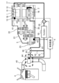
- FIG. 1 is a diagram showing a configuration of a vehicle drive system according to a first embodiment of the present invention.
- the drive system of this embodiment includes a motor 1, a gear assembly 3 arranged in the output direction of the motor 1, an engine 4, and a control device 5.
- the rotor 11 is arranged on the inner peripheral side of the stator 10, and the winding 12 is wound around the stator 10.
- the type of the motor 1 may be a permanent magnet motor having a permanent magnet, a synchronous motor having a field winding, an induction motor having a cage-shaped conductor, a reluctance motor formed only by a rotor core, or the like, and a magnetic field is generated from the rotor.
- the components to be generated and their shapes are not limited.
- the stator 10 is fixed to the inner peripheral side of the frame 16 by shrink fitting or the like.
- the frame 16 is formed by low-pressure casting, die casting, or the like, and its shape and dimensions are not limited, including the bracket that supports the bearing.
- the winding 12 is composed of distributed winding or concentrated winding, and the winding 12 may be composed of either a square wire or a round wire, and the winding method and type of the winding are not limited.
- the motor 1 generates a rotating magnetic field as well as a current flowing through the winding 12 due to the current and voltage output from the inverter 2, and rotates the rotor 11 to generate torque.
- the rotor 11 is connected to the gear assembly 3 through the shaft 17, and the vehicle is driven by connecting the gear output shaft 23 inside the gear assembly 3 to the axle.
- the motor 1 is not for traveling that converts electrical energy into kinetic energy of a vehicle, but may be for regeneration that generates electrical energy from the kinetic energy of a vehicle, and may be used for both traveling and regeneration.
- the motor 1 may be cooled by a refrigerant such as water. At this time, the lubricating oil 30 may be heated to a higher temperature than the refrigerant.
- the gear assembly 3 is configured by arranging a plurality of gears 22 inside the gearbox 21, and the gear ratio of the gears 22 is configured so as to reduce the rotational speed of the motor 1.
- the gear 22 is composed of parallel shaft spur gears, but the gear 22 may be a planetary gear alone or a combination of planetary gears and spur gears, and the configuration and gear ratio of parallel shafts or uniaxial gears are not limited.
- a differential gear is usually arranged between the gear assembly 3 and the axle.
- the lubricating oil 30 is retained in the lower part of the gear assembly 3, and the lubricating oil 30 communicates between the motor 1 and the gear assembly 3 to connect the motor 1 and the gear 22. It is configured to lubricate and cool. A part of the gear 22 in the gear assembly 3 is immersed in the lubricating oil 30, and as the gear 22 rotates, the lubricating oil 30 diffuses into the gear assembly 3 to lubricate the gear 22.
- the engine 4 is an internal combustion engine having a piston in a cylinder, generates torque for running, and / or drives a generator.
- the exhaust pipe 43 is provided with a catalytic converter 44.
- the three-way catalyst in the catalyst converter 44 cannot exhibit exhaust gas purification performance at a low temperature, and the catalyst temperature needs to exceed 500 ° C.
- the exhaust temperature of the engine 4 ranges from about 200 ° C. when idling to about 800 ° C. during full-load operation, and the catalyst cannot exhibit purification performance during cold start.
- an oil passage for circulating the lubricating oil 30 is provided between the gear assembly 3 and the catalytic converter 44.
- the oil passage of this embodiment includes an oil passage 51 for introducing the lubricating oil 30 from the gear assembly 3 to the catalytic converter 44, and an oil passage 52 for returning the lubricating oil 30 from the catalytic converter 44 to the motor 1.
- the oil passage 52 may be provided so as to extend downward from the catalytic converter 44 so that the lubricating oil 30 in the catalytic converter 44 can escape by gravity.
- the oil passage 52 is provided with a pump 59 for circulating the lubricating oil 30. The details of the operating conditions of the pump 59 will be described later, but it is preferable to operate when the temperature of the catalytic converter 44 is lower than the oil temperature.
- the pump 59 may be provided on the downstream side of the catalyst converter 44 to suck the lubricating oil 30 staying in the catalyst converter 44. Further, since the lubricating oil 30 cooled by the catalytic converter 44 flows to the pump 59, the high-temperature lubricating oil 30 does not flow to the pump 59, and the pump 59 can be driven in a state where the temperature load is small.
- the lubricating oil 30 that has returned from the oil passage 52 to the motor 1 may be configured to be directly applied to the winding 12 of the motor 1, or the lubricating oil 30 discharged from the oil passage 52 is stored inside the motor 1.
- the winding 12 may be cooled.
- the winding 12 in contact with the lubricating oil 30 may be configured so as to go toward a position (coil end) protruding from the outer diameter of the stator 10.
- the lubricating oil 30 that has cooled the motor 1 stays in the lower part of the gear assembly 3 through the communication passage between the motor 1 and the gear assembly 3 after being warmed by the winding 12.
- the lubricating oil 30 lubricates the gear 22 after cooling the coil of the motor 1, and is guided to the catalytic converter 44. Therefore, the lubricating oil 30 lubricates the gear 22 with the high temperature (that is, low viscosity) lubricating oil 30. After that, the high temperature lubricating oil 30 supplies heat to the catalyst.
- the drive system of this embodiment is provided with three temperature sensors 61 to 63.
- the temperature sensor 61 is provided in the motor 1 and measures the temperature of the winding 12.
- the temperature sensor 62 is provided in the gear assembly 3 and measures the temperature (oil temperature) of the lubricating oil 30.
- the temperature sensor 63 is provided in the catalyst converter 44 and measures the temperature of the catalyst.
- the pump 59 is switched on and off according to the temperature of each part measured by the sensors 61 to 63. Further, in another embodiment described later, in addition to turning on / off the pump 59, the opening / closing of the valve is controlled by the temperature of each part measured by the sensors 61 to 63.
- the control device 5 is composed of a computer (microcomputer) including an arithmetic unit, a memory, and an input / output device.
- the control device 5 may be provided separately from the inverter 2 or may be provided in the inverter 2 that controls the motor 1.
- the arithmetic unit includes a processor and executes a program stored in memory. A part of the processing performed by the arithmetic unit by executing the program may be executed by another arithmetic unit (for example, hardware such as FPGA (Field Programmable Gate Array) or ASIC (Application Specific Integrated Circuit)).
- FPGA Field Programmable Gate Array
- ASIC Application Specific Integrated Circuit
- the memory includes ROM and RAM which are non-volatile storage elements.
- the ROM stores an invariant program (for example, BIOS) and the like.
- RAM is a high-speed and volatile storage element such as DRAM (Dynamic Random Access Memory), and SRAM (Static Random Access). It is a non-volatile storage element such as Memory), and stores a program executed by an arithmetic unit and data used when the program is executed.
- the program executed by the arithmetic unit is stored in the non-volatile storage device which is the non-temporary storage medium of the control device 5.
- the input / output device is an interface for transmitting processing contents to the outside and receiving data from the outside according to a predetermined protocol.
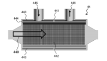
- 2 to 5 are diagrams showing the configuration of the catalytic converter 44 of this embodiment.
- the catalyst converter 44 shown in FIG. 2 has a double side wall of a case 441 that houses the catalyst 442 and allows exhaust gas to pass therethrough, and an oil passage 443 of the lubricating oil 30 is provided in the case 441.
- the oil passage 443 is provided with an inflow port 445 into which the lubricating oil 30 flows in from the exhaust gas inflow direction (indicated by an arrow 440) and an outflow port 446 in which the lubricating oil 30 flows out in the exhaust gas outflow direction.
- An air layer 444 is provided between the case 441 and the catalyst 442.
- the air layer 444 functions as a heat insulating material so that the temperature of the catalyst 442 does not rise sharply due to the high-temperature lubricating oil 30 and the temperature of the lubricating oil 30 does not rise due to the high-temperature exhaust gas.
- the catalyst converter 44 shown in FIG. 3 has a double side wall of a case 441 that houses a catalyst 442 and allows exhaust gas to pass therethrough, and an oil passage 443 for lubricating oil 30 is provided in the case 441.
- the arrow 440 in the figure indicates the direction in which the exhaust gas flows.
- the case 441 is provided with an inflow port 445 into which the lubricating oil 30 flows in from the radial direction and an outflow port 446 in which the lubricating oil 30 flows out in the radial direction.
- An air layer 444 is provided between the case 441 and the catalyst 442.
- the air layer 444 functions as a heat insulating material so that the temperature of the catalyst 442 does not rise sharply due to the high-temperature lubricating oil 30 and the temperature of the lubricating oil 30 does not rise due to the high-temperature exhaust gas.
- the catalyst converter 44 shown in FIG. 4 accommodates the catalyst 442 and is provided with an oil passage 443 of the lubricating oil 30 along the inner surface of the side wall of the case 441 through which the exhaust gas is passed.
- the oil passage 443 is provided with an inflow port 445 into which the lubricating oil 30 flows in from the exhaust gas inflow direction (indicated by an arrow 440) and an outflow port 446 in which the lubricating oil 30 flows out in the exhaust gas outflow direction.
- the catalytic converter 44 shown in FIG. 4 does not have an air layer, the temperature of the lubricating oil 30 can be avoided even if the air layer is not provided by controlling the flow of the lubricating oil 30 in a sufficient amount. ..
- a spiral oil passage 443 is provided in the case 441.
- the oil passage 443 may be provided on the inner surface or the outer surface of the case 441.
- an inflow port 445 into which the lubricating oil 30 flows in and an outflow port 446 in which the lubricating oil 30 flows out are provided.
- the catalytic converter 44 shown in FIG. 5 may or may not have an air layer.
- the arrow 440 in the figure indicates the direction in which the exhaust gas flows.
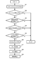
- FIG. 6 is a flowchart showing an example of control of the drive system of this embodiment.
- control device 5 determines whether the engine 4 is stopped (102). In step 102, the elapsed time from the latest start of the engine 4 to the sufficient warming of the catalyst 442 may be determined. If the engine 4 is in operation, it is presumed that the catalyst 442 is warmed by the exhaust gas, so this process is terminated.
- the engine 4 is stopped, it is estimated that the catalyst 442 is cold, so it is determined whether the temperature of the catalyst 442 is equal to or lower than a predetermined threshold value (for example, 550 ° C.) (103). If the temperature of the catalyst 442 is higher than a predetermined threshold value, it is not necessary to heat the catalyst 442, and this process is terminated.
- a predetermined threshold value for example, 550 ° C.
- the temperature of the catalyst 442 is equal to or lower than a predetermined threshold value, it is necessary to warm the catalyst 442, so it is determined whether the temperature of the lubricating oil 30 is equal to or higher than the predetermined threshold value (104). If the temperature of the lubricating oil 30 is lower than a predetermined threshold value, the lubricating oil 30 cannot be warmed, and this process is terminated.
- the temperature and oil temperature of the catalyst 442 in steps 103 and 104 are determined by determining whether the temperature of the lubricating oil 30 is higher than the temperature of the catalyst 442, instead of comparing each with a predetermined threshold value. If the temperature of 30 is higher than the temperature of the catalyst 442, the process may proceed to step 105.
- the catalyst 442 can be warmed, so it is determined whether the temperature of the winding 12 is equal to or higher than the predetermined threshold value (105). If the temperature of the winding 12 is lower than a predetermined threshold value, the lubricating oil 30 cannot be warmed and the catalyst 442 cannot be warmed, so that this process is terminated.
- the pump 59 is operated so that the lubricating oil 30 circulates in the oil passage (106), and the catalytic converter 44.
- the motor 1 is cooled by the lubricating oil 30 cooled in (107)
- the gear 22 is lubricated by the lubricating oil 30 warmed by the motor 1 (108)
- the lubricating oil 30 warmed by the motor 1 is used in the catalytic converter 44. It is circulated and the catalyst 442 is heated to raise the temperature (109).
- the pump 59 is controlled to operate when the catalyst 442 is not warmed up, and after the catalyst 442 is warmed up, the pump 59 is controlled to operate if the coil temperature is sufficient for warming up the catalyst 442. Will be done. If the high-temperature lubricating oil 30 that is insufficiently cooled is circulated after the temperature of the catalyst 442 has risen, the winding 12 becomes hot and the winding 12 may be burnt. Therefore, when the temperature of the lubricating oil 30 is high, it is necessary to circulate a large amount of the lubricating oil 30 and control so that the lubricating oil 30 and the winding 12 are lowered.
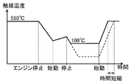
- 7 and 8 are graphs showing the temperature change of the catalyst 442 in the drive system of this embodiment.
- the catalyst 442 when the engine 4 is operating, the catalyst 442 is warmed up to 550 ° C. or higher by the exhaust gas of the engine 4, but when the engine 4 is stopped, the temperature of the catalyst 442 drops. After that, when the engine 4 is repeatedly started and stopped, the temperature of the catalyst 442 changes up and down. However, in this embodiment, if the motor 1 is operating even when the engine 4 is stopped, the catalyst 442 is warmed up by the heat generated by the winding 12, so that the temperature of the catalyst 442 is maintained at about 100 ° C. .. Therefore, it is possible to shorten the time until the temperature of the catalyst 442 rises when the engine 4 is started, as compared with the conventional control of the catalyst temperature shown by the broken line.
- the pump 59 may be operated to warm up the catalyst 442.
- the time until the temperature of the catalyst 442 rises when the engine 4 is started can be shortened. ..
- the lubricating oil 30 of the gear assembly 3 heated by the motor 1 is flowed through the catalyst converter 44 to catalyze the catalyst.
- the 442 can be warmed up and kept warm. Therefore, the operation of the pump 59 is switched based on the temperature of the catalyst 442, the temperature of the lubricating oil 30, and the temperature of the winding 12, and the lubricating oil 30 is circulated. Further, the motor 1 can be cooled without providing a heat exchanger for cooling the lubricating oil 30 heated by the motor 1.
- the time until the temperature of the catalyst 442 rises can be shortened, it is not necessary to warm up the catalyst converter 44, and the fuel consumption and the power consumption can be reduced.
- an electric vehicle equipped with an internal combustion engine such as a PHEV
- the internal combustion engine if the internal combustion engine is stopped for a long time, the effect of raising the temperature of the catalyst 442 by the exhaust gas cannot be obtained, and the temperature of the catalyst 442 decreases.
- the catalyst 442 can be maintained at a temperature higher than room temperature even if the engine 4 is stopped for a long time or stopped many times.
- FIG. 9 is a diagram showing a configuration of a vehicle drive system according to a second embodiment of the present invention.
- the drive system of the second embodiment is provided with a detour oil passage 53 and a radiator 55 in the oil passage.
- a detour oil passage 53 and a radiator 55 in the oil passage.
- the configuration different from that of the first embodiment will be mainly described, and the description of the configuration having the same function as that of the first embodiment will be omitted.
- the drive system of this embodiment includes a motor 1, a gear assembly 3, an engine 4, and a control device 5.
- the oil passages of this embodiment bypass the oil passage 51 for introducing the lubricating oil 30 from the gear assembly 3 to the catalyst converter 44, the oil passage 52 for returning the lubricating oil 30 from the catalyst converter 44 to the motor 1, and the catalyst converter 44. It is composed of a detour oil passage 53 connecting the oil passage 51 and the oil passage 52. A valve 56 is provided at the branch point from the oil passage 51 to the detour oil passage 53. When the valve 56 is open, the lubricating oil 30 from the gear assembly 3 flows into the catalytic converter 44, and when the valve 56 is closed, the lubricating oil 30 from the gear assembly 3 flows into the bypass oil passage 53 and flows into the catalytic converter 44. do not.
- the oil passage 52 may be provided so as to extend downward from the catalytic converter 44 so that the lubricating oil 30 in the catalytic converter 44 can escape due to gravity.
- the oil passage 52 is provided with a radiator 55 for cooling the lubricating oil 30 heated by the motor 1.
- a pump 59 for circulating the lubricating oil 30 is provided on the downstream side of the radiator 55 of the oil passage 52. As described above in the first embodiment, the pump 59 may operate when the temperature of the catalytic converter 44 is lower than the oil temperature.
- the pump 59 may be provided on the downstream side of the catalyst converter 44 to suck the lubricating oil 30 staying in the catalyst converter 44.
- the lubricating oil 30 returned from the oil passage 52 to the motor 1 may be configured to be directly applied to the winding 12 of the motor 1, or the lubricating oil 30 discharged from the oil passage 52 may be collected and wound inside the motor 1.
- the wire 12 may be cooled. Further, the winding 12 in contact with the lubricating oil 30 may be configured so as to go toward a position (coil end) protruding from the outer diameter of the stator 10.
- the lubricating oil 30 that has cooled the motor 1 stays in the lower part of the gear assembly 3 through the communication passage between the motor 1 and the gear assembly 3 after being warmed by the winding 12.
- the lubricating oil 30 lubricates the gear 22 after cooling the coil of the motor 1, and is guided to the catalytic converter 44. Therefore, the lubricating oil 30 lubricates the gear 22 with the high temperature (that is, low viscosity) lubricating oil 30. After that, the high temperature lubricating oil 30 supplies heat to the catalyst. Further, by closing the valve 56 when the catalytic converter 44 becomes hot, the lubricating oil 30 from the gear assembly 3 bypasses the catalytic converter 44 and flows into the bypass oil passage 53. As a result, deterioration of the lubricating oil 30 can be suppressed without bringing the lubricating oil 30 into contact with the high-temperature catalyst 442.
- the radiator 55 is provided downstream of the catalyst converter 44, the lubricating oil 30 which has become hot in the motor 1 can transfer the heat to the catalyst converter 44 before the heat is released by the radiator 55. Further, the lubricating oil 30 cooled by the catalytic converter 44 can be further cooled by the radiator 55 to improve the cooling efficiency of the motor 1.
- the pump 59 is provided downstream of the radiator 55, the lubricating oil 30 cooled by the radiator 55 flows to the pump 59, the high-temperature lubricating oil 30 does not flow to the pump 59, and the pump 59 is driven in a state where the temperature load is small. it can.
- FIG. 10 is a diagram showing a configuration of a vehicle drive system according to a third embodiment of the present invention.
- the drive system of the third embodiment is provided with a circulating oil passage 54 and a radiator 55 in the oil passage.
- the configurations different from those of the first and second embodiments described above will be mainly described, and the description of the configurations having the same functions as those of the first and second embodiments will be omitted.
- the oil passages of this embodiment include an oil passage 51 for introducing the lubricating oil 30 from the gear assembly 3 to the catalyst converter 44, an oil passage 52 for returning the lubricating oil 30 from the catalyst converter 44 to the motor 1, and a radiator for the lubricating oil 30. It is composed of a circulating oil passage 54 that circulates through 55.
- a valve 57 is provided on the upstream side of the catalytic converter 44. When the valve 57 is open, the lubricating oil 30 from the gear assembly 3 flows into the catalytic converter 44, and when the valve 57 is closed, the lubricating oil 30 from the gear assembly 3 does not flow into the catalytic converter 44.
- the oil passage 52 may be provided so as to extend downward from the catalytic converter 44 so that the lubricating oil 30 in the catalytic converter 44 can escape due to gravity.
- the oil passage 52 is provided with a radiator 55 for cooling the lubricating oil 30 heated by the motor 1.
- a pump 59 for circulating the lubricating oil 30 is provided on the downstream side of the radiator 55 of the oil passage 52. As described above in the first embodiment, the pump 59 may operate when the temperature of the catalytic converter 44 is lower than the oil temperature.
- the pump 59 may be provided on the downstream side of the catalyst converter 44 to suck the lubricating oil 30 staying in the catalyst converter 44.
- the lubricating oil 30 returned from the oil passage 52 to the motor 1 may be configured to be directly applied to the winding 12 of the motor 1, or the lubricating oil 30 discharged from the oil passage 52 may be collected and wound inside the motor 1.
- the wire 12 may be cooled. Further, the winding 12 in contact with the lubricating oil 30 may be configured so as to go toward a position (coil end) protruding from the outer diameter of the stator 10.
- the lubricating oil 30 that has returned to the motor 1 is warmed by the winding 12, and then stays in the lower part of the gear assembly 3 through the communication passage between the motor 1 and the gear assembly 3.
- the circulating oil passage 54 is provided so as to communicate the oil passage 52 near the outlet of the lubricating oil 30 of the catalytic converter 44 and the outlet of the lubricating oil 30 of the radiator 55.
- a valve 58 is provided in the middle of the circulation oil passage 54.
- a circulation pump may be provided in the middle of the circulation oil passage 54.
- valve 57 is opened and the valve 58 is closed to circulate the lubricating oil 30 to the catalytic converter 44 and the radiator 55 to cool the lubricating oil 30 warmed by the motor 1.
- the lubricating oil 30 lubricates the gear 22 after cooling the coil of the motor 1, and is guided to the catalytic converter 44. Therefore, the lubricating oil 30 lubricates the gear 22 with the high temperature (that is, low viscosity) lubricating oil 30. After that, the high temperature lubricating oil 30 supplies heat to the catalyst. Further, when the temperature of the catalytic converter 44 becomes high, the lubricating oil 30 can be circulated through the radiator 55 through the circulating oil passage 54 to efficiently cool the lubricating oil 30 and suppress the deterioration of the lubricating oil 30.
- the radiator 55 is provided downstream of the catalyst converter 44, the lubricating oil 30 which has become hot in the motor 1 can transfer the heat to the catalyst converter 44 before the heat is released by the radiator 55. Further, the lubricating oil 30 cooled by the catalytic converter 44 can be further cooled by the radiator 55 to improve the cooling efficiency of the motor 1.
- the pump 59 is provided downstream of the radiator 55, the lubricating oil 30 cooled by the radiator 55 flows to the pump 59, the high-temperature lubricating oil 30 does not flow to the pump 59, and the pump 59 is driven in a state where the temperature load is small. it can.
- the drive system includes an internal combustion engine (engine 4), a catalyst unit (catalytic converter 44) that purifies the exhaust of the internal combustion engine, and at least one for traveling or regeneration. It is provided with a motor 1 to be used and flow paths (oil passages 50, 51, 52) formed so as to allow an oil-based medium (lubricating oil 30) for lubricating the motor 1 to flow in the vicinity of a catalyst section (catalyst 442).
- the medium 30 is heated by the motor 1 and heat-exchanged by the catalyst converter 44 to heat the catalyst 442. Therefore, when the medium 30 is warmed up by a water-cooled refrigerant by using an oil-based medium 30 having a temperature higher than that of water.
- the warm-up efficiency of the catalytic converter 44 can be improved, and the catalytic converter 44 can be quickly warmed up to a high temperature and kept warm. It is possible to reduce the consumption of fuel for warming up and keeping the catalyst converter 44 warm.
- a gear assembly 3 for transmitting the output of the motor 1 using the gear 22 is provided, and the lubricating oil 30 for lubricating the gear 22 is used as the oil-based medium. That is, the transmission oil is circulated to the catalytic converter 44 to warm up the catalytic converter 44 and raise the temperature. Since the lubricating oil 30 is supplied to the transmission after cooling the winding 12 of the motor 1 and introduced into the catalytic converter 44, the high temperature of the lubricating oil 30 can be maintained to warm up the catalytic converter 44.
- the gear assembly 3 can be lubricated with the lubricating oil 30 having a high temperature and a low viscosity, and the lubrication resistance of the gear assembly 3 can be reduced, as compared with the case where the motor 1 is directly introduced into the catalytic converter 44.
- the oil-based medium 30 is heated by contacting the winding 12 of the motor 1 and cooling the winding 12, the lubrication resistance of the gear assembly 3 is reduced by raising the temperature of the oil-based medium 30. Later, heat can be used to warm up the catalyst 442.
- the catalytic converter is converted by using the oil-based medium 30 as compared with the case where the catalytic converter 44 is warmed up by the water-cooled refrigerant.
- the 44 can be warmed up to a high temperature to keep it warm.
- valves 56 and 57 for controlling the oil-based medium 30 so as not to flow in the vicinity of the catalyst 442 when the temperature of the catalyst 442 is higher than a predetermined threshold value are provided, the lubricating oil 30 is heated to a high temperature when warming up is unnecessary. It is possible to suppress the deterioration of the lubricating oil 30 without doing so.
- a pump 59 for circulating the oil-based medium 30 is provided, and the pump 59 is controlled so that the oil-based medium 30 does not flow in the vicinity of the catalyst 442 when the temperature of the motor 1 is lower than a predetermined threshold value, so that warm-up can be performed.
- the energy consumption by the pump 59 when it is not possible can be reduced.
- the present invention is not limited to the above-described embodiment, but includes various modifications and equivalent configurations within the scope of the attached claims.
- the above-described examples have been described in detail in order to explain the present invention in an easy-to-understand manner, and the present invention is not necessarily limited to those having all the described configurations.
- a part of the configuration of one embodiment may be replaced with the configuration of another embodiment.
- the configuration of another embodiment may be added to the configuration of one embodiment.
- other configurations may be added / deleted / replaced with respect to a part of the configurations of each embodiment.
- each of the above-described configurations, functions, processing units, processing means, etc. may be realized by hardware by designing a part or all of them by, for example, an integrated circuit, and the processor realizes each function. It may be realized by software by interpreting and executing the program to be executed.
- Information such as programs, tables, and files that realize each function can be stored in a memory, a hard disk, a storage device such as an SSD (Solid State Drive), or a recording medium such as an IC card, an SD card, or a DVD.
- SSD Solid State Drive
- a recording medium such as an IC card, an SD card, or a DVD.
- control lines and information lines indicate those that are considered necessary for explanation, and do not necessarily indicate all the control lines and information lines that are necessary for implementation. In practice, it can be considered that almost all configurations are interconnected.
Landscapes
- Engineering & Computer Science (AREA)
- Chemical & Material Sciences (AREA)
- Combustion & Propulsion (AREA)
- Mechanical Engineering (AREA)
- Chemical Kinetics & Catalysis (AREA)
- General Engineering & Computer Science (AREA)
- Transportation (AREA)
- Power Engineering (AREA)
- Toxicology (AREA)
- Health & Medical Sciences (AREA)
- Automation & Control Theory (AREA)
- Exhaust Gas After Treatment (AREA)
- Cooling, Air Intake And Gas Exhaust, And Fuel Tank Arrangements In Propulsion Units (AREA)
- Hybrid Electric Vehicles (AREA)
Abstract
Description
Memory)のような不揮発性の記憶素子であり、演算装置が実行するプログラム及びプログラムの実行時に使用されるデータを格納する。演算装置が実行するプログラムは、制御装置5の非一時的記憶媒体である不揮発性の記憶装置に格納される。
また、モータ1で加熱された潤滑油30を冷却する熱交換器を設けることなく、モータ1を冷却できる。
実施例2では、前述した実施例1と異なる構成について主に説明し、実施例1と同じ機能を有する構成の説明は省略する。
3…ギアアセンブリ
4…エンジン
5…制御装置
10…ステータ
11…ロータ
12…巻線
16…フレーム
17…シャフト
21…ギアボックス
22…歯車
23…ギア出力軸
30…潤滑油
43…排気管
44…触媒コンバータ
50、51、52…油路
53…迂回油路
54…循環油路
55…ラジエータ
56、57、58…バルブ
59…ポンプ
61、62、63…温度センサ
Claims (6)
- 駆動システムであって、
内燃機関と、
前記内燃機関の排気を浄化する触媒部と、
走行用又は回生用の少なくとも一方に用いられるモータと、
前記モータを潤滑する油性媒体を前記触媒部の近傍に流すように形成される流路とを備え、
前記油性媒体は、前記モータで加熱され、前記触媒部で熱交換されることによって、前記触媒部を加熱することを特徴とする駆動システム。 - 請求項1に記載の駆動システムであって、
前記モータの出力を歯車を用いて伝達するギアアセンブリを備え、
前記油性媒体は、前記歯車を潤滑する潤滑油であることを特徴とする駆動システム。 - 請求項1に記載の駆動システムであって、
前記油性媒体は、前記モータの巻線と接触して、前記巻線を冷却することによって加熱されることを特徴とする駆動システム。 - 請求項1に記載の駆動システムであって、
前記モータは冷媒によって冷却されており、
前記油性媒体は、前記冷媒より高温に加熱されることを特徴とする駆動システム。 - 請求項1に記載の駆動システムであって、
前記触媒部の温度が所定の閾値より高い場合、前記油性媒体を前記触媒部の近傍に流さないように制御するバルブを備えることを特徴とする駆動システム。 - 請求項1に記載の駆動システムであって、
前記油性媒体を前記流路で循環させるポンプを備え、
前記ポンプは、前記モータの温度が所定の閾値より低い場合、前記油性媒体を触媒部の近傍に流さないように制御されることを特徴とする駆動システム。
Priority Applications (4)
| Application Number | Priority Date | Filing Date | Title |
|---|---|---|---|
| EP20873794.0A EP4043703A4 (en) | 2019-10-07 | 2020-09-08 | DRIVE SYSTEM |
| US17/766,915 US12512727B2 (en) | 2019-10-07 | 2020-09-08 | Drive system |
| JP2021550510A JP7308279B2 (ja) | 2019-10-07 | 2020-09-08 | 駆動システム |
| CN202080079473.9A CN114728574B (zh) | 2019-10-07 | 2020-09-08 | 驱动系统 |
Applications Claiming Priority (2)
| Application Number | Priority Date | Filing Date | Title |
|---|---|---|---|
| JP2019184613 | 2019-10-07 | ||
| JP2019-184613 | 2019-10-07 |
Publications (1)
| Publication Number | Publication Date |
|---|---|
| WO2021070535A1 true WO2021070535A1 (ja) | 2021-04-15 |
Family
ID=75437145
Family Applications (1)
| Application Number | Title | Priority Date | Filing Date |
|---|---|---|---|
| PCT/JP2020/033880 Ceased WO2021070535A1 (ja) | 2019-10-07 | 2020-09-08 | 駆動システム |
Country Status (5)
| Country | Link |
|---|---|
| US (1) | US12512727B2 (ja) |
| EP (1) | EP4043703A4 (ja) |
| JP (1) | JP7308279B2 (ja) |
| CN (1) | CN114728574B (ja) |
| WO (1) | WO2021070535A1 (ja) |
Cited By (1)
| Publication number | Priority date | Publication date | Assignee | Title |
|---|---|---|---|---|
| JP7452343B2 (ja) | 2020-09-15 | 2024-03-19 | 日産自動車株式会社 | ハイブリッド車両制御方法及びハイブリッド車両制御装置 |
Families Citing this family (1)
| Publication number | Priority date | Publication date | Assignee | Title |
|---|---|---|---|---|
| JP7443822B2 (ja) * | 2020-02-28 | 2024-03-06 | 三菱ふそうトラック・バス株式会社 | 排気浄化装置 |
Citations (9)
| Publication number | Priority date | Publication date | Assignee | Title |
|---|---|---|---|---|
| US4391235A (en) * | 1981-05-28 | 1983-07-05 | Majkrzak David S | Vehicle exhaust gas warm-up heater system |
| JPH06276614A (ja) | 1993-03-17 | 1994-09-30 | Hitachi Ltd | ハイブリッド車の駆動装置 |
| JP2000265910A (ja) | 1999-03-16 | 2000-09-26 | Nissan Motor Co Ltd | 自己着火型ガソリンエンジンを備えたハイブリッド車両 |
| JP2008092727A (ja) * | 2006-10-04 | 2008-04-17 | Toyota Motor Corp | 車両の駆動装置 |
| JP2008121466A (ja) * | 2006-11-09 | 2008-05-29 | Toyota Motor Corp | 電動過給機 |
| JP2008247084A (ja) * | 2007-03-29 | 2008-10-16 | Toyota Motor Corp | ハイブリッド車両の触媒昇温装置 |
| JP2017227163A (ja) | 2016-06-22 | 2017-12-28 | いすゞ自動車株式会社 | 昇温装置 |
| JP6315143B1 (ja) * | 2017-07-25 | 2018-04-25 | トヨタ自動車株式会社 | 車両の制御装置 |
| JP2019043427A (ja) * | 2017-09-05 | 2019-03-22 | トヨタ自動車株式会社 | ハイブリッド車両 |
Family Cites Families (28)
| Publication number | Priority date | Publication date | Assignee | Title |
|---|---|---|---|---|
| JPH1193643A (ja) * | 1997-09-25 | 1999-04-06 | Toyota Motor Corp | 内燃機関の排気浄化装置 |
| JP3574049B2 (ja) * | 1999-08-09 | 2004-10-06 | 本田技研工業株式会社 | ハイブリッド自動車 |
| JP2004052672A (ja) * | 2002-07-19 | 2004-02-19 | Toyota Motor Corp | ハイブリッド車及びその制御方法 |
| JP2006291916A (ja) * | 2005-04-14 | 2006-10-26 | Toyota Motor Corp | 駆動システムおよびこれを搭載する自動車並びに駆動システムの制御方法 |
| JP2010059862A (ja) * | 2008-09-03 | 2010-03-18 | Toyota Motor Corp | 排気熱回収装置 |
| DE102009013943A1 (de) * | 2009-03-19 | 2010-09-23 | Frank Will | Ölschmiersystem |
| JP5039098B2 (ja) * | 2009-07-24 | 2012-10-03 | 日産自動車株式会社 | ハイブリッド車両の制御装置 |
| US10975747B2 (en) * | 2012-08-24 | 2021-04-13 | Advanced Technology Emission Solutions Inc. | Gaseous emissions treatment structures |
| SE536740C2 (sv) * | 2012-11-07 | 2014-07-08 | BAE Systems Hägglunds Aktiebolag | Förfarande och anordning för vätskekylning av en elmotor |
| JP2015074393A (ja) * | 2013-10-10 | 2015-04-20 | トヨタ自動車株式会社 | 車体前部構造 |
| CN103633775B (zh) | 2013-11-29 | 2015-11-11 | 华南理工大学 | 一种内置差减总成的电动汽车驱动电机 |
| DE102014009293A1 (de) * | 2014-06-11 | 2015-12-17 | Eduard Hilberer | Motorradhybridantrieb mit einem Klauenumschaltgetriebe und schaltbarer Mehrscheibenlamellenkupplung bei welchem der Elektromotor bei stehender Kurbelwelle die Getriebeeingangswelle zum elektrischen Fahren antreibt. |
| DE102014218453A1 (de) * | 2014-09-15 | 2016-03-17 | Schaeffler Technologies AG & Co. KG | Elektromotor mit Ölkühlung |
| DE102014015868A1 (de) * | 2014-10-25 | 2016-04-28 | Daimler Ag | Abgasnachbehandlungseinrichtung für eine Verbrennungskraftmaschine, insbesondere eines Kraftwagens |
| JP2016108998A (ja) * | 2014-12-04 | 2016-06-20 | トヨタ自動車株式会社 | 自動車 |
| JP2016199210A (ja) * | 2015-04-14 | 2016-12-01 | 美浜株式会社 | 温調システムおよび温調方法ならびに触媒ヒーター |
| JP6253001B1 (ja) * | 2016-09-29 | 2017-12-27 | マツダ株式会社 | 車両の制御装置 |
| CN206397556U (zh) * | 2016-12-15 | 2017-08-11 | 浙江吉利罗佑发动机有限公司 | 一种增程式电动汽车机油预热装置 |
| WO2018135066A1 (ja) * | 2017-01-17 | 2018-07-26 | 日本碍子株式会社 | 発熱システム、排気ガス浄化装置、及びハニカム構造体の再生方法 |
| DE102017213213B4 (de) * | 2017-08-01 | 2020-03-26 | Ford Global Technologies, Llc | Verfahren zur Steuerung eines Abgaswärmemanagementsystems, Abgaswärmemanagementsystem, Kraftfahrzeug sowie Computerprogrammprodukt |
| JP7003606B2 (ja) * | 2017-12-05 | 2022-01-20 | トヨタ自動車株式会社 | ハイブリッド自動車およびこれに搭載される制御装置 |
| US10844824B2 (en) * | 2018-02-13 | 2020-11-24 | Ford Global Technologies, Llc | System and method for a range extender engine of a hybrid electric vehicle |
| CN108258850A (zh) * | 2018-03-16 | 2018-07-06 | 深圳派赛科技有限公司 | 电机油水双冷系统 |
| US10272767B1 (en) * | 2018-03-23 | 2019-04-30 | Sf Motors, Inc. | Dual loop liquid cooling of integrated electric drivetrain |
| CN208057205U (zh) * | 2018-03-30 | 2018-11-06 | 河南交通职业技术学院 | 一种汽车尾气净化装置 |
| CN108952906A (zh) * | 2018-08-17 | 2018-12-07 | 李奥鑫 | 一种尾气处理器 |
| JP7276686B2 (ja) * | 2019-02-27 | 2023-05-18 | マツダ株式会社 | 車両駆動装置 |
| US11156197B1 (en) * | 2020-10-01 | 2021-10-26 | Ford Global Technologies, Llc | Methods and systems for engine cranking |
-
2020
- 2020-09-08 EP EP20873794.0A patent/EP4043703A4/en active Pending
- 2020-09-08 CN CN202080079473.9A patent/CN114728574B/zh active Active
- 2020-09-08 JP JP2021550510A patent/JP7308279B2/ja active Active
- 2020-09-08 US US17/766,915 patent/US12512727B2/en active Active
- 2020-09-08 WO PCT/JP2020/033880 patent/WO2021070535A1/ja not_active Ceased
Patent Citations (9)
| Publication number | Priority date | Publication date | Assignee | Title |
|---|---|---|---|---|
| US4391235A (en) * | 1981-05-28 | 1983-07-05 | Majkrzak David S | Vehicle exhaust gas warm-up heater system |
| JPH06276614A (ja) | 1993-03-17 | 1994-09-30 | Hitachi Ltd | ハイブリッド車の駆動装置 |
| JP2000265910A (ja) | 1999-03-16 | 2000-09-26 | Nissan Motor Co Ltd | 自己着火型ガソリンエンジンを備えたハイブリッド車両 |
| JP2008092727A (ja) * | 2006-10-04 | 2008-04-17 | Toyota Motor Corp | 車両の駆動装置 |
| JP2008121466A (ja) * | 2006-11-09 | 2008-05-29 | Toyota Motor Corp | 電動過給機 |
| JP2008247084A (ja) * | 2007-03-29 | 2008-10-16 | Toyota Motor Corp | ハイブリッド車両の触媒昇温装置 |
| JP2017227163A (ja) | 2016-06-22 | 2017-12-28 | いすゞ自動車株式会社 | 昇温装置 |
| JP6315143B1 (ja) * | 2017-07-25 | 2018-04-25 | トヨタ自動車株式会社 | 車両の制御装置 |
| JP2019043427A (ja) * | 2017-09-05 | 2019-03-22 | トヨタ自動車株式会社 | ハイブリッド車両 |
Non-Patent Citations (1)
| Title |
|---|
| See also references of EP4043703A4 |
Cited By (1)
| Publication number | Priority date | Publication date | Assignee | Title |
|---|---|---|---|---|
| JP7452343B2 (ja) | 2020-09-15 | 2024-03-19 | 日産自動車株式会社 | ハイブリッド車両制御方法及びハイブリッド車両制御装置 |
Also Published As
| Publication number | Publication date |
|---|---|
| EP4043703A1 (en) | 2022-08-17 |
| US20220416624A1 (en) | 2022-12-29 |
| CN114728574B (zh) | 2025-09-12 |
| US12512727B2 (en) | 2025-12-30 |
| JP7308279B2 (ja) | 2023-07-13 |
| EP4043703A4 (en) | 2023-11-15 |
| CN114728574A (zh) | 2022-07-08 |
| JPWO2021070535A1 (ja) | 2021-04-15 |
Similar Documents
| Publication | Publication Date | Title |
|---|---|---|
| US10960752B2 (en) | Electric vehicle | |
| JP6652041B2 (ja) | 車両用冷却装置 | |
| CN113227546B (zh) | 车辆热交换系统 | |
| JP2011116366A (ja) | ハイブリッド電気自動車における冷却システムの補助ポンプ構成 | |
| GB2454349A (en) | Heating hybrid vehicle engine oil | |
| JP2008008489A (ja) | 車両の燃料経済性を改善するための方法および装置 | |
| CN106930811A (zh) | 运行车辆电加热器的再生制动功率 | |
| CN102171425A (zh) | 冷却系统 | |
| CN102935801A (zh) | 车用散热系统及其控制装置和控制方法、工程机械 | |
| JP4789820B2 (ja) | エンジン冷却装置 | |
| JP7308291B2 (ja) | 冷却制御装置、電動システム、及び冷却制御方法 | |
| JP7308279B2 (ja) | 駆動システム | |
| JP4075189B2 (ja) | 動力出力装置 | |
| CN110439664B (zh) | 一种汽车发动机的冷却系统 | |
| JP2010095017A (ja) | ハイブリッド車およびその制御方法 | |
| JP3889396B2 (ja) | ハイブリッド車両の冷却装置 | |
| JP2016112933A (ja) | 車両用バッテリの暖機装置 | |
| WO2014039287A1 (en) | Thermal system transmission cooler | |
| JP2023017567A (ja) | 車両用冷却システム | |
| JP2002204550A (ja) | モータの冷却装置 | |
| CN103917758A (zh) | 电动机通过热管的冷却 | |
| JP2009057864A (ja) | 車両の制御装置、制御方法およびその方法をコンピュータで実現されるプログラムならびにそのプログラムを記録した記録媒体 | |
| JP2012031811A (ja) | 電動ウォーターポンプの制御装置 | |
| JP2004257266A (ja) | 車両用駆動装置の温度制御装置 | |
| JP2010169010A (ja) | 内燃機関の冷却装置 |
Legal Events
| Date | Code | Title | Description |
|---|---|---|---|
| 121 | Ep: the epo has been informed by wipo that ep was designated in this application |
Ref document number: 20873794 Country of ref document: EP Kind code of ref document: A1 |
|
| ENP | Entry into the national phase |
Ref document number: 2021550510 Country of ref document: JP Kind code of ref document: A |
|
| NENP | Non-entry into the national phase |
Ref country code: DE |
|
| ENP | Entry into the national phase |
Ref document number: 2020873794 Country of ref document: EP Effective date: 20220509 |
|
| WWG | Wipo information: grant in national office |
Ref document number: 202080079473.9 Country of ref document: CN |
|
| WWG | Wipo information: grant in national office |
Ref document number: 17766915 Country of ref document: US |