WO2021070695A1 - 液を供給する装置 - Google Patents
液を供給する装置 Download PDFInfo
- Publication number
- WO2021070695A1 WO2021070695A1 PCT/JP2020/037085 JP2020037085W WO2021070695A1 WO 2021070695 A1 WO2021070695 A1 WO 2021070695A1 JP 2020037085 W JP2020037085 W JP 2020037085W WO 2021070695 A1 WO2021070695 A1 WO 2021070695A1
- Authority
- WO
- WIPO (PCT)
- Prior art keywords
- piston
- measuring
- drive mechanism
- stroke
- measuring unit
- Prior art date
- Legal status (The legal status is an assumption and is not a legal conclusion. Google has not performed a legal analysis and makes no representation as to the accuracy of the status listed.)
- Ceased
Links
Images


Classifications
-
- H—ELECTRICITY
- H01—ELECTRIC ELEMENTS
- H01M—PROCESSES OR MEANS, e.g. BATTERIES, FOR THE DIRECT CONVERSION OF CHEMICAL ENERGY INTO ELECTRICAL ENERGY
- H01M50/00—Constructional details or processes of manufacture of the non-active parts of electrochemical cells other than fuel cells, e.g. hybrid cells
- H01M50/60—Arrangements or processes for filling or topping-up with liquids; Arrangements or processes for draining liquids from casings
- H01M50/609—Arrangements or processes for filling with liquid, e.g. electrolytes
-
- F—MECHANICAL ENGINEERING; LIGHTING; HEATING; WEAPONS; BLASTING
- F04—POSITIVE - DISPLACEMENT MACHINES FOR LIQUIDS; PUMPS FOR LIQUIDS OR ELASTIC FLUIDS
- F04B—POSITIVE-DISPLACEMENT MACHINES FOR LIQUIDS; PUMPS
- F04B13/00—Pumps specially modified to deliver fixed or variable measured quantities
- F04B13/02—Pumps specially modified to deliver fixed or variable measured quantities of two or more fluids at the same time
-
- F—MECHANICAL ENGINEERING; LIGHTING; HEATING; WEAPONS; BLASTING
- F04—POSITIVE - DISPLACEMENT MACHINES FOR LIQUIDS; PUMPS FOR LIQUIDS OR ELASTIC FLUIDS
- F04B—POSITIVE-DISPLACEMENT MACHINES FOR LIQUIDS; PUMPS
- F04B13/00—Pumps specially modified to deliver fixed or variable measured quantities
-
- F—MECHANICAL ENGINEERING; LIGHTING; HEATING; WEAPONS; BLASTING
- F04—POSITIVE - DISPLACEMENT MACHINES FOR LIQUIDS; PUMPS FOR LIQUIDS OR ELASTIC FLUIDS
- F04B—POSITIVE-DISPLACEMENT MACHINES FOR LIQUIDS; PUMPS
- F04B17/00—Pumps characterised by combination with, or adaptation to, specific driving engines or motors
- F04B17/03—Pumps characterised by combination with, or adaptation to, specific driving engines or motors driven by electric motors
-
- F—MECHANICAL ENGINEERING; LIGHTING; HEATING; WEAPONS; BLASTING
- F04—POSITIVE - DISPLACEMENT MACHINES FOR LIQUIDS; PUMPS FOR LIQUIDS OR ELASTIC FLUIDS
- F04B—POSITIVE-DISPLACEMENT MACHINES FOR LIQUIDS; PUMPS
- F04B23/00—Pumping installations or systems
- F04B23/04—Combinations of two or more pumps
- F04B23/06—Combinations of two or more pumps the pumps being all of reciprocating positive-displacement type
-
- F—MECHANICAL ENGINEERING; LIGHTING; HEATING; WEAPONS; BLASTING
- F04—POSITIVE - DISPLACEMENT MACHINES FOR LIQUIDS; PUMPS FOR LIQUIDS OR ELASTIC FLUIDS
- F04B—POSITIVE-DISPLACEMENT MACHINES FOR LIQUIDS; PUMPS
- F04B49/00—Control, e.g. of pump delivery, or pump pressure of, or safety measures for, machines, pumps, or pumping installations, not otherwise provided for, or of interest apart from, groups F04B1/00 - F04B47/00
- F04B49/06—Control using electricity
-
- F—MECHANICAL ENGINEERING; LIGHTING; HEATING; WEAPONS; BLASTING
- F04—POSITIVE - DISPLACEMENT MACHINES FOR LIQUIDS; PUMPS FOR LIQUIDS OR ELASTIC FLUIDS
- F04B—POSITIVE-DISPLACEMENT MACHINES FOR LIQUIDS; PUMPS
- F04B49/00—Control, e.g. of pump delivery, or pump pressure of, or safety measures for, machines, pumps, or pumping installations, not otherwise provided for, or of interest apart from, groups F04B1/00 - F04B47/00
- F04B49/12—Control, e.g. of pump delivery, or pump pressure of, or safety measures for, machines, pumps, or pumping installations, not otherwise provided for, or of interest apart from, groups F04B1/00 - F04B47/00 by varying the length of stroke of the working members
- F04B49/121—Lost-motion device in the driving mechanism
-
- F—MECHANICAL ENGINEERING; LIGHTING; HEATING; WEAPONS; BLASTING
- F04—POSITIVE - DISPLACEMENT MACHINES FOR LIQUIDS; PUMPS FOR LIQUIDS OR ELASTIC FLUIDS
- F04B—POSITIVE-DISPLACEMENT MACHINES FOR LIQUIDS; PUMPS
- F04B49/00—Control, e.g. of pump delivery, or pump pressure of, or safety measures for, machines, pumps, or pumping installations, not otherwise provided for, or of interest apart from, groups F04B1/00 - F04B47/00
- F04B49/20—Control, e.g. of pump delivery, or pump pressure of, or safety measures for, machines, pumps, or pumping installations, not otherwise provided for, or of interest apart from, groups F04B1/00 - F04B47/00 by changing the driving speed
-
- H—ELECTRICITY
- H01—ELECTRIC ELEMENTS
- H01M—PROCESSES OR MEANS, e.g. BATTERIES, FOR THE DIRECT CONVERSION OF CHEMICAL ENERGY INTO ELECTRICAL ENERGY
- H01M10/00—Secondary cells; Manufacture thereof
- H01M10/04—Construction or manufacture in general
-
- Y—GENERAL TAGGING OF NEW TECHNOLOGICAL DEVELOPMENTS; GENERAL TAGGING OF CROSS-SECTIONAL TECHNOLOGIES SPANNING OVER SEVERAL SECTIONS OF THE IPC; TECHNICAL SUBJECTS COVERED BY FORMER USPC CROSS-REFERENCE ART COLLECTIONS [XRACs] AND DIGESTS
- Y02—TECHNOLOGIES OR APPLICATIONS FOR MITIGATION OR ADAPTATION AGAINST CLIMATE CHANGE
- Y02E—REDUCTION OF GREENHOUSE GAS [GHG] EMISSIONS, RELATED TO ENERGY GENERATION, TRANSMISSION OR DISTRIBUTION
- Y02E60/00—Enabling technologies; Technologies with a potential or indirect contribution to GHG emissions mitigation
- Y02E60/10—Energy storage using batteries
-
- Y—GENERAL TAGGING OF NEW TECHNOLOGICAL DEVELOPMENTS; GENERAL TAGGING OF CROSS-SECTIONAL TECHNOLOGIES SPANNING OVER SEVERAL SECTIONS OF THE IPC; TECHNICAL SUBJECTS COVERED BY FORMER USPC CROSS-REFERENCE ART COLLECTIONS [XRACs] AND DIGESTS
- Y02—TECHNOLOGIES OR APPLICATIONS FOR MITIGATION OR ADAPTATION AGAINST CLIMATE CHANGE
- Y02P—CLIMATE CHANGE MITIGATION TECHNOLOGIES IN THE PRODUCTION OR PROCESSING OF GOODS
- Y02P70/00—Climate change mitigation technologies in the production process for final industrial or consumer products
- Y02P70/50—Manufacturing or production processes characterised by the final manufactured product
Definitions
- the present invention relates to a device that supplies a liquid.
- Japanese Patent Application Laid-Open No. 2013-12340 discloses an apparatus capable of more accurately controlling the injection amount of the electrolytic solution.
- This injection device is arranged in a measuring unit in which a piston moves in a measuring space in a cylinder, a dispenser for injecting an electrolytic solution, a first conduit connecting the upper end of the measuring space and the dispenser, and a first conduit.
- the back pressure valve is activated by the change in back pressure due to the operation of the piston, the inlet valve that turns on and off the liquid flowing into the measuring space through the second pipeline, and the back pressure valve is temporarily opened by the operating rod. It has an open unit to be set.
- One aspect of the present invention is a device that simultaneously supplies liquids to a plurality of containers.
- This device includes a first measuring unit in which a first piston moves in a first measuring space in a first cylinder to be replenished with liquid, and a second measuring space in a second cylinder to be replenished with liquid.
- a second measuring unit in which the second piston moves, a first dispenser communicated with the first measuring space, and a first dispenser for injecting a liquid into the first container, and a second weighing A second dispenser that is communicated with the space so that the second dispenser that injects the liquid into the second container and the first piston and the second piston move up and down in the first stroke in synchronization with each other.
- a first stroke conversion mechanism that is arranged between the first piston and the drive mechanism and that independently converts and transmits the first stroke of the drive mechanism to the first piston. It has a first stroke conversion mechanism that independently controls the movement amount of the first piston with respect to the movement amount of the second piston.
- This device is a device that operates a plurality of weighing units (weighing devices) at the same time (in parallel) with a common drive mechanism, and the number of drive mechanisms can be reduced with respect to the number of weighing units. Therefore, not only is it economical, but also the arrangement density of the measuring unit can be improved. Therefore, this device can quickly inject liquid into a large number of containers. Further, by arranging the measuring unit for each of the plurality of containers, the volume of the liquid to be injected into each container can be accurately measured and supplied (injection, injection).
- the first stroke conversion mechanism includes a connecting mechanism that sandwiches a spring arranged between the drive mechanism and the first piston, and a stopper that stops the movement of the first piston at a predetermined position. ..
- the spring By sandwiching the spring in the connecting mechanism that moves with the first stroke provided by the drive mechanism, the spring can be contracted by the stopper to convert the stroke amount (movement amount). Therefore, the movement amount of the first piston can be independently controlled (limited) with respect to the movement amount supplied by the drive mechanism, and the stroke amount (movement amount) of the first piston can be changed to the stroke amount (movement) of the second piston. It can be controlled individually (independently) for (quantity). Further, the size of the first measuring space and the size of the second measuring space may be different, or different ones may be combined.
- a stroke conversion mechanism may be arranged between the second piston and the drive mechanism.
- a direct connection mechanism may be provided in which the movement of the second piston is directly controlled by the drive mechanism.
- the movement of the drive mechanism can be guided by the movement of the second piston. That is, it is possible to prevent the movement of the drive mechanism from becoming unstable due to the spring or the like included in the stroke conversion mechanism, and it is possible to ensure the accuracy of weighing in each measuring unit.
- the first weighing space may be larger than the second weighing space.
- This device is a third measuring unit in which a third piston moves in a third measuring space in a third cylinder to be replenished with liquid, and a third dispenser communicating with the third measuring space. , May have a third dispenser that injects the liquid into the third container.
- the drive mechanism operates the first piston, the second piston, and the third piston synchronously.
- This device is arranged between the third piston and the drive mechanism, and includes a third stroke conversion mechanism that independently converts and transmits the first stroke of the drive mechanism to the third piston. You may.
- the movement amount of the third piston can be controlled independently of the movement amount of the first piston and the movement amount of the second piston.
- the first measuring unit and the third measuring unit may be arranged symmetrically with respect to the second measuring unit.
- the first weighing unit, the second weighing unit, and the third weighing unit may be arranged linearly in this order.
- the second piston of the central second measuring unit may be directly operated by the drive mechanism by the direct connection mechanism without using the stroke conversion mechanism.
- the second piston can be used as a guide to stabilize the movement of the drive mechanism while maintaining the weighing accuracy of each weighing unit.
- the second weighing space may be smaller than the first weighing space and the third weighing space.
- This device can be used as a device for injecting an electrolytic solution into a battery case. Therefore, as a system for manufacturing a battery cell by injecting an electrolytic solution into a battery case having a built-in electrode, a system having the above-described device for injecting an electrolytic solution as a liquid into a battery case (battery can) which is a container. May be provided.
- Front view of the liquid injection device Rear view of the liquid injection device.
- Side view of the liquid injection device
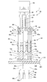
- FIG. 1 shows a front view of an apparatus according to an embodiment of the present invention (triple plunger pump, electrolyte supply device, liquid injection device, supply device), and FIG. 2 shows a view from the back surface. It is shown, and FIG. 3 shows a state seen from the side surface.
- This device 1 is a liquid injection device adopted in a system 110 for manufacturing a battery cell 99.
- the liquid injection device 1 is a device (plunger pump) that supplies the electrolytic solution 19 to the battery container (battery case, battery can) 90 in which the electrode 95 is built.
- the battery container 90 is arranged inside the decompression chamber 100, and the inside of the decompression chamber 100 is decompressed by a vacuum pump so as to have a predetermined pressure (negative pressure, decompression atmosphere).
- the system 110 includes a plurality of liquid injection devices 1 arranged at an appropriate pitch on the upper wall 101 of the decompression chamber 100, and the electrolytic solution 19 is injected into a large number of battery containers 90 in the decompression chamber 100 simultaneously or in parallel. To. In the following, one liquid injection device 1 will be extracted and described.
- the liquid injection device 1 includes a measuring unit 10 arranged on the upper wall (top plate) 101 of the decompression chamber 100, a dispenser 20 arranged downstream of the measuring unit 10, and a drive mechanism 30.
- the electrolytic solution 19 to be replenished from a reservoir (reservoir tank, not shown) arranged upstream of the measuring unit 10 is weighed and injected into the container 90 via the dispenser 20.
- the measuring unit 10 includes a cylinder 11 and a piston 12. The cylinder 11 extends vertically, and the piston 12 moves in the cylinder 11 in the vertical direction (vertical direction).
- the area where the piston 12 enters and exits inside the cylinder 11 is the measuring space 13, and is measured in the measuring space 13 by controlling the amount of entering and exiting the piston 12 (stroke amount, moving amount).
- the amount of the electrolytic solution 19 can be freely controlled (adjusted).
- the piston 12 extends upward through the space 15 that holds the sealing liquid, and is operated by the drive mechanism 30 including the servomotor 33.
- An example of the servomotor 33 is a stepping motor, in which the rotation amount, the rotation speed, and the rotation direction are controlled by the control unit 39, and the piston 12 is operated so as to move up and down with a predetermined stroke (first stroke).
- the first stroke (movement amount) provided by the drive mechanism 30 can be accurately controlled by pulse-controlling the servomotor 33.
- the liquid injection device 1 accurately supplies a predetermined amount to the container 90 by injecting the electrolytic solution 19 measured by the measuring unit 10 into the container 90 once or a plurality of times.
- a typical control unit 39 includes hardware resources including a CPU and a memory, and controls the liquid injection device 1 by executing a program (program product).
- the electrolytic solution 19 measured by the measuring unit 10 is injected from above into the battery container 90 by the dispenser 20.
- the dispenser 20 includes a discharge nozzle 21 arranged in the battery container 90 or near the upper end of the battery container 90, a single tube (cylindrical or syringe, hereinafter a syringe) 22 to which the discharge nozzle 21 is mounted at the lower end, and discharge.
- a needle valve (stop valve) 23 arranged inside the nozzle 21 to open and close the tip of the discharge nozzle 21, a valve control rod 25 provided so as to penetrate the inside of the syringe 22 up and down, and a valve control rod 25.
- the needle valve 23 is normally off (normally closed) and includes means (for example, a coil spring) 26 for urging the needle valve 23 to the tip of the discharge nozzle 21 via the valve control rod 25.
- the syringe 22 penetrates the upper wall 101 of the decompression chamber 100 and extends vertically, and the tip reaches the battery container 90 arranged inside the decompression chamber 100. Therefore, the lower end of the syringe 22 which is the tip of the dispenser 20 extends below the lower end of the measuring space 13 of the measuring unit 10 arranged on the upper wall 101, and the electrolytic cylinder filled in the measuring space 13 is filled.
- the liquid 19 flows to the battery container 90 under static pressure (static head). Further, a decompression atmosphere is formed around the discharge nozzle 21 which is the tip (lower end) of the syringe 22, and the electrolytic solution 19 is injected into the battery container 90 of the decompression chamber 100 due to the pressure difference.
- the electrolytic solution 19 leaks from the discharge nozzle 21 even when the discharge nozzle 21 faces the decompression atmosphere. Can be suppressed and the drainage property is improved. Further, by opening the needle valve 23 before injection, gas such as air can be removed from the inside of the liquid injection device 1 including the measuring space 13 by using the negative pressure of the pressure reducing chamber 100.
- the dispenser 20 communicates with the measuring space 13 via a port 18 provided on the upper side of the measuring space 13 of the measuring unit 10.
- the electrolytic solution 19 is replenished from the reservoir to the measuring space 13 via the port 17 provided on the lower side.
- the communication passage 50 connecting the dispenser 20 and the port 18 of the measuring unit 10 includes a back pressure valve 55 arranged at a position corresponding to the vicinity of the lower end portion of the measuring space 13 of the vertically extending pipeline 51.
- the back pressure valve 55 includes a ball 56 which is a valve body and a coil spring 57 which urges the ball 56 upward and keeps the back pressure valve 55 closed (off).
- the coil spring 57 is set to apply a pressure to the ball 56 so that the electrolytic solution 19 does not flow through the back pressure valve 55 unless the piston 12 of the measuring unit 10 operates (stroke, in this case, moves downward).
- the back pressure valve 55 is set so that the electrolytic solution 19 does not flow even if the difference pressure between the maximum negative pressure (vacuum degree) of the pressure reducing chamber 100 and the atmospheric pressure is applied as the back pressure.
- the back pressure valve 55 acts as a check valve when an abnormal situation occurs in which the negative pressure in the pressure reducing chamber 100 breaks and becomes atmospheric pressure.
- liquid injection device 1 when used to inject the liquid into the container 90 at atmospheric pressure other than the decompression chamber 100, when an abnormal situation occurs in which the internal pressure of the syringe 22 becomes higher than the internal pressure of the measuring space 13. Acts as a check valve.
- the liquid injection device 1 temporarily sets (fixes) the back pressure valve 55 to open, and depressurizes the liquid injection device 1 by utilizing the negative pressure of the pressure reducing chamber 100 to release air or the like from the liquid injection device 1.
- the opening unit 59 includes an operating rod 58 that operates the ball 56, which is the valve body of the back pressure valve 55, through the straight pipe portion 51.
- the operation rod 58 may be completely retracted, or the tip of the operation rod 58 may be inserted into the straight pipe portion 51.
- the back pressure valve 55 operates normally by pulling up the operating rod 58 from the straight pipe portion 51.
- the cross-sectional area through which the electrolytic solution 19 of the straight pipe portion 51 passes becomes small, so that when the electrolytic solution 19 passes through the straight pipe portion 51, Pressure loss can be controlled.
- the force applied to the back pressure valve 55 may change, albeit slightly.
- the position of the piston 12 moving in the measuring space 13 and the timing of opening and closing the back pressure valve 55 can be controlled by the position of the operating rod 58.
- the liquid injection device 1 injects (dispenss) the electrolytic solution 19 into the battery container 90 once or in a plurality of times.
- a predetermined amount of the electrolytic solution 19 flows into the measuring space 13.
- the back pressure for opening the back pressure valve 55 is not applied to the back pressure valve 55, and the back pressure valve 55 is maintained in a closed state.
- the electrolytic solution 19 flows in from the inlet port 17 on the lower side of the measuring space 13 via the inlet valve 5.
- the needle valve 23 is opened.
- the measuring space 13 is shut off from the system upstream of the inlet valve 5, and the static pressure of the system upstream of the inlet valve 5 is not applied.
- the cross-sectional area of the measuring space 13 composed of the cylinder 11 and the piston 12 is one digit or more, usually two to three orders of magnitude or more larger than the cross-sectional area of the pipe.
- the back pressure valve 55 After opening the needle valve 23, stroke the piston 12 downward.
- the back pressure valve 55 opens, and an amount of electrolytic solution 19 corresponding to the movement of the piston 12 is stably discharged from the tip of the discharge nozzle 21.
- the back pressure valve 55 opens and closes in response to the movement of the piston 12 instantly (immediately). Therefore, when the piston 12 stops the stroke, the back pressure valve 55 can pressure-separate the measuring unit 10 and the dispenser 20 almost instantly. Therefore, even if the tip of the dispenser 20 is placed in a reduced pressure (vacuum) state, it is possible to prevent a situation in which the electrolytic solution 19 in the measuring space 13 is pulled by the reduced pressure and flows out in a large amount.
- the liquid injection device 1 includes three sets of measuring units 10a to 10c and dispensers 20a to 20c, and a drive mechanism 30 for synchronously (simultaneously) driving these sets. Including. Each dispenser 20a to 20c can inject the liquid 19 into a plurality of different containers 90a to 90c.
- the liquid injection device 1 is a device that simultaneously supplies the liquid 19 to a plurality of containers 90a to 90c, and provides the first measuring space 13a in the first cylinder 11a to which the electrolytic liquid 19 is replenished with the first piston 12a.
- the third measuring space 13c in the replenished third cylinder 11c includes a third measuring unit 10c in which the third piston 12c moves.
- the first measuring unit 10a and the third measuring unit 10c are arranged symmetrically with respect to the second measuring unit 10b.
- the first measuring unit 10a, the second measuring unit 10b, and the third measuring unit 10c are linearly arranged in this order.
- the first weighing unit 10a, the second weighing unit 10b, and the third weighing unit 10c may be arranged so as to form an isosceles triangle with the second weighing unit 10b as the apex.
- the liquid injection device 1 is a first dispenser 20a communicating with the first measuring space 13a, and is a first dispenser 20a for injecting the liquid 19 into the first container 90a and a second measuring space.
- a second dispenser 20b communicating with the 13b, a second dispenser 20b for injecting the liquid 19 into the second container 90b, and a third dispenser 20c communicating with the third weighing space 13c.
- a third dispenser 20c that injects the liquid 19 into the third container 90c.
- the liquid injection device 1 includes a drive mechanism 30 that simultaneously (parallel) operates the first piston 12a, the second piston 12b, and the third piston 12c, and the first piston 12a and the drive mechanism 30.
- a first stroke conversion mechanism (stroke control mechanism) 60a which is arranged between them and controls the movement amount of the first piston 12a independently of the movement amounts of the other pistons 12b and 12c, and a third piston 12c.
- a third stroke conversion mechanism (stroke control mechanism) 60c which is arranged between the drive mechanism 30 and the third piston 12c and controls the movement amount of the third piston 12c independently of the movement amounts of the other pistons 12a and 12b. including.
- the stroke conversion mechanisms 60a and 60c independently convert the first stroke provided by the drive mechanism 30 and transmit it to the pistons 12a and 12c, respectively.
- the liquid injection device 1 further includes a direct connection mechanism 62 that directly controls the second piston 12b by the drive mechanism 30.
- the second piston 12b is directly operated by the drive mechanism 30 without going through the stroke conversion mechanism.
- the drive mechanism 30 includes a servomotor 33, a ball screw 34 driven by the servomotor 33, a carriage 35 driven up and down by the ball screw 34, and a set of ball splines 36 supporting the carriage 35 on the left and right sides.
- the hollow shaft 37 which moves integrally with the carriage 35 and is arranged coaxially with the ball screw 34, and the pistons 12a to 12c are connected so as to move the pistons 12a to 12c synchronously (at the same time, in parallel) via the shaft 37.
- the second piston 12b is directly connected to the connecting block 38, and the first piston 12a and the third piston 12c are connected to the connecting block 38 via the stroke conversion mechanisms 60a and 60c, respectively.
- the first stroke conversion mechanism 60a and the third stroke conversion mechanism 60c have a common configuration, and a connecting mechanism 64 having a spring 61 sandwiched between the drive mechanism 30 and the respective pistons 12a and 12c. And a stopper 63 that stops the movement of the pistons 12a and 12c at predetermined positions.
- the connecting mechanism 64 is arranged so as to penetrate the spring (coil spring) 61 arranged so as to be sandwiched between the flanges (rings, protrusions) 69 of the pistons 12a and 12c and the connecting block 38, respectively, and the coil spring 61. Includes connecting rod 65.
- the connecting mechanism 64 including the spring 61 and the connecting rod 65 implements a mechanism as a link type suspension in which the maximum length (distance, interval) is defined by the connecting rod 65, and the coil spring 61 and the connecting rod 65 May be arranged coaxially or in parallel.
- the stopper 63 is an engaging portion (locking portion, stopper portion) 68 that hits the flange 69 of the pistons 12a and 12c that also serve as a supporting portion of the coil spring 61 and controls the movement (movement amount) of the respective pistons, and the engaging portion 68.
- the capacity of the central second measuring space 13b is set to be smaller than the capacity of the left and right first measuring spaces 13a and the third measuring space 13c.
- the measuring unit 10 having the measuring space 13 having a small capacity is arranged in the center, and the measuring unit 10 having the measuring space 13 having a larger capacity is arranged on the left and right.
- the left and right measuring units 10a having a large capacity and the left and right measuring units 10a and
- the amount of liquid discharged from the measuring spaces 13a and 13c of 10c reaches a predetermined value first with respect to the amount of liquid discharged from the measuring space 13b of the central measuring unit 10b. Therefore, the stroke amount (first stroke) of the drive mechanism 30 is converted into a short stroke amount by the connecting mechanism 64 and the stopper 63 of the stroke conversion mechanisms 60a and 60c, and the position (movement amount) defined by the stopper 63.
- Can stop restrict
- the stroke amount of the drive mechanism 30 (first stroke, operation amount of the servomotor 33) is set according to the movement amount of the piston 12b of the central measuring unit 10b having the smallest capacity. Therefore, the drive mechanism 30 drives the piston 12b via the connecting block 38 and the direct connection mechanism 62, and lowers the piston 12b until a predetermined amount of the electrolytic solution 19 is discharged from the measuring space 13b. During that time, the springs 61 of the stroke conversion mechanisms 60a and 60c contract, and the pistons 12a and 12c do not descend even if the connecting block 38 descends after the movement is stopped by the stopper 63. Therefore, the stroke conversion mechanisms 60a and 60c absorb the difference in stroke required to discharge a predetermined amount of liquid from the pistons 12a to 12c.
- a liquid injection device 1 having measuring units 10a to 10c constituting three pumps, in which the injection amounts from the respective measuring units 10a to 10b are matched with high accuracy, is used as a liquid injection device. Can be manufactured and provided with normal processing accuracy.
- the size of the measurement space 13b of the central second measurement unit 10b directly controlled by the drive mechanism 30 is relative to the size of the measurement space 13b. It is desirable that the sizes of the weighing spaces 13a and 13c of the weighing units 10a and 10c on both sides are clearly large. Therefore, the liquid injection device 1 may be configured by combining the measuring units 10 having different sizes of the measuring spaces 13 from the design stage.
- the stroke conversion mechanism 60 it is also possible to install the stroke conversion mechanism 60 on any of the three pistons 12a to 12c and control each piston 12a to 12c independently.
- the stroke conversion mechanism 60 often uses a member having low rigidity such as a spring for converting the stroke and a variable length for controlling the interval. Therefore, the load on the connecting block 38 fluctuates on a piston-by-piston basis, which may be an obstacle for the connecting block 38 to move up and down horizontally. It is desirable that the connecting block 38 of the drive mechanism 30 always moves up and down in a horizontal state in order to stably supply a constant stroke to the pistons 12a to 12c. When the connecting block 38 is tilted, the amount of liquid injected into the containers 90a to 90c via the respective dispensers 20a to 20c can be a factor to fluctuate.
- this liquid injection device 1 by arranging ball splines 36 on both sides of the carriage 35 that moves up and down by the servomotor 33, the carriage 35 moves up and down in an extremely stable state in the horizontal direction. Further, a second piston 12b attached to the center of the connecting block 38 that moves up and down in conjunction with the carriage 35 is directly connected to the connecting block 38. That is, the first measuring unit 10a and the third measuring unit 10c are arranged at symmetrical positions with respect to the second measuring unit 10b provided with the second piston 12b that is directly connected to the drive mechanism 30 by the direct connecting mechanism 62. doing. The second piston 12b arranged at the center of symmetry is directly connected to the connecting block 38 without being provided with the stroke conversion mechanism 60, and the central piston 12b also serves as a guide when the connecting block 38 moves up and down. Can be done.
- the pistons 12b that are directly connected as guides on the left and right sides of the connecting block 38 it is necessary to configure the left and right weighing units with no tolerance. Further, by arranging the pistons 12b that also serve as guides in the center of the pistons 12a to 12c arranged in a row on the left and right, and arranging the stroke conversion mechanisms 60a and 60c including springs on the left and right, the load acting on the connecting block 38 varies. Can be suppressed, the load balance can be adjusted, and the connecting block 38 can be moved up and down in the most smooth and horizontal state.
- the liquid injection device 1 can be driven by one drive mechanism 30 by connecting three measuring units 10a to 10c which may have different capacities.
- the electrolytic solution 19 measured accurately and consistently can be injected into the three containers 90a to 90c at the same time (in parallel).
- the number of drive mechanisms 30 that occupy a large space can be reduced, and the measuring units 10a to 10c can be arranged at the minimum intervals, so that the efficiency of the liquid injection work for a plurality of containers 90 can be improved. It can be greatly improved, including efficiency. Further, by reducing the number of drive mechanisms 30, the equipment cost and running cost required for injecting liquid can be reduced.
- the liquid injection device 1 in which three measuring units 10a to 10c are arranged in a row is described as an example, but it is a liquid injection device in which two measuring units are simultaneously operated by one drive mechanism 30. Alternatively, it may be a liquid injection device in which four or more measuring units 10 are operated by one drive mechanism 30. For example, five measuring units 10 are arranged in a cross shape, the piston 12 of the central measuring unit 10 is directly operated by the connecting block 38, and the pistons 12 of the other measuring units 10 are operated via a stroke conversion mechanism. It may be a device. Further, in this example, the system 110 for injecting the electrolytic solution 19 to manufacture the battery cell 99 is described as an example, but the injected liquid is not limited to the electrolytic solution.
- the cylinders 11a to 11c forming the plurality of measuring spaces 13a to 13c are composed of one member as the cylinder block 11x, but the cylinders 11a to 11c may be composed of a plurality of members or blocks.
- the second cylinder 11b may be a block common to the first cylinder 11a, or may be an independent block.
- the third cylinder 11c may be a block common to the first cylinder 11a and the second cylinder 11b, or may be an independent block.
Landscapes
- Engineering & Computer Science (AREA)
- Mechanical Engineering (AREA)
- General Engineering & Computer Science (AREA)
- Chemical & Material Sciences (AREA)
- Chemical Kinetics & Catalysis (AREA)
- Electrochemistry (AREA)
- General Chemical & Material Sciences (AREA)
- Manufacturing & Machinery (AREA)
- Reciprocating Pumps (AREA)
- Filling, Topping-Up Batteries (AREA)
- Basic Packing Technique (AREA)
- Feeding, Discharge, Calcimining, Fusing, And Gas-Generation Devices (AREA)
Abstract
注液装置(1)は、第1のシリンダ(11a)内の第1の計量空間(13a)を第1のピストン(12a)が動く第1の計量ユニット(10a)と、第2のシリンダ(11b)内の第2の計量空間(13b)を第2のピストン(12b)が動く第2の計量ユニット(10b)と、第1の容器(90a)に液(19)を注入する第1のディスペンサ(20a)と、第2の容器(90b)に液を注入する第2のディスペンサ(20b)と、第1のピストンおよび第2のピストンを同期して操作する駆動機構(30)と、第1のピストンと駆動機構との間に配置され、駆動機構の第1のストロークを、第1のピストンに対し、独自に変換して伝達する第1のストローク変換機構(60a)であって、第1のピストンの移動量を第2のピストンの移動量に対して独立して制御する第1のストローク変換機構とを有する。
Description
本発明は、液を供給する装置に関するものである。
日本国特開2013-12340号公報には、電解液の注入量をさらに精度よく制御できる装置が開示されている。この注入装置は、シリンダ内の計量空間をピストンが動く計量ユニットと、電解液を注入するディスペンサと、計量空間の上端部とディスペンサとをつなぐ第1の管路と、第1の管路に配置され、ピストンの動作に伴う背圧の変化により作動する背圧弁と、第2の管路を介して計量空間へ流入する液をオンオフする入口弁と、操作棒により背圧弁を一時的に開にセットする開放ユニットとを有する。
数多くの容器に対して電解液などを迅速に注入できる装置が求められている。
本発明の一態様は、複数の容器に液を同時に供給する装置である。この装置は、液が補充される第1のシリンダ内の第1の計量空間を第1のピストンが動く第1の計量ユニットと、液が補充される第2のシリンダ内の第2の計量空間を第2のピストンが動く第2の計量ユニットと、第1の計量空間に連通された第1のディスペンサであって、第1の容器に液を注入する第1のディスペンサと、第2の計量空間に連通された第2のディスペンサであって、第2の容器に液を注入する第2のディスペンサと、第1のピストンおよび前記第2のピストンを同期して第1のストロークで上下するように操作する駆動機構と、第1のピストンと駆動機構との間に配置され、駆動機構の第1のストロークを、第1のピストンに対し、独自に変換して伝達する第1のストローク変換機構であって、第1のピストンの移動量を第2のピストンの移動量に対して独立して制御する第1のストローク変換機構とを有する。
この装置は、複数の計量ユニット(計量デバイス)を共通の駆動機構で、同時に(並列に)操作する装置であり、計量ユニットの数に対して駆動機構の数を減らすことができる。このため、経済的であるだけでなく、計量ユニットの配置密度を向上できる。したがって、この装置により、数多くの容器に対して液を迅速に注入できる。また、複数の容器のそれぞれに対して計量ユニットを配置することにより、それぞれの容器に注入する液の容量を精度よく計量して供給(注入、注液)することができる。一方、共通の駆動機構により複数の計量ユニットのピストンを同時に(並列に)一定のストロークで駆動する装置の場合、個々の容器に対する注入量の制御に高い精度が要求されると、全ての計量ユニットの計量空間のサイズが高い精度で均一であることが要求され、そのような要求を低コストで実現することは難しい。この装置においては、ピストンと駆動機構との間に、駆動機構の第1のストロークを、ピストン毎に、独自に変換して伝達するストローク変換機構を設け、計量空間のサイズの差を容易に吸収したり、逆に、計量空間のサイズに意図的な差を設けることにより高精度での注入量の制御を可能としている。すなわち、駆動機構の第1のストロークを、第1のピストンに対し、独自に変換して伝達する第1のストローク変換機構を設け、第1のピストンの移動量を第2のピストンの移動量に対して独立して制御することを可能としている。
第1のストローク変換機構の一例は、駆動機構と第1のピストンとの間に配置されたバネを挟んだ連結機構と、第1のピストンの移動を所定の位置で停止するストッパとを含むものである。駆動機構が提供する第1のストロークで動く連結機構中にバネを挟むことにより、ストッパによりバネを縮めてストローク量(移動量)を変換できる。したがって、駆動機構により供給される移動量に対して第1のピストンの移動量を独自に制御(制限)でき、第1のピストンのストローク量(移動量)を第2のピストンのストローク量(移動量)に対し個別に(独立して)制御できる。また、第1の計量空間の大きさと第2の計量空間の大きさとが異なってもよく、異なるものを組み合わせてもよい。
第2のピストンと駆動機構との間にストローク変換機構を配置してもよい。第2のピストンの動きを駆動機構により直に制御する直結機構を設けてもよい。第2のピストンが、ストローク変換機構を介さずに駆動機構により直に操作される装置においては、駆動機構の動きを第2のピストンの動きでガイドできる。すなわち、ストローク変換機構に含まれるバネなどにより駆動機構の動きが不安定になることを抑制でき、それぞれの計量ユニットにおける計量の精度を確保できる。第2のピストンを駆動機構の第1のストロークで直に制御するためには、第1の計量空間が第2の計量空間より大きくてもよい。
この装置は、液が補充される第3のシリンダ内の第3の計量空間を第3のピストンが動く第3の計量ユニットと、第3の計量空間に連通された第3のディスペンサであって、第3の容器に液を注入する第3のディスペンサとを有していてもよい。駆動機構は、第1のピストン、第2のピストンおよび第3のピストンを同期して操作する。この装置は、第3のピストンと駆動機構との間に配置され、駆動機構の第1のストロークを、第3のピストンに対し、独自に変換して伝達する第3のストローク変換機構を備えていてもよい。第3のピストンの移動量を第1のピストンの移動量および第2のピストンの移動量に対して独立して制御することができる。
第1の計量ユニットおよび第3の計量ユニットは、第2の計量ユニットを中心とした対称な位置に配置されてもよい。例えば、第1の計量ユニット、第2の計量ユニットおよび第3の計量ユニットは、この順番で直線的に配置されてもよい。中心となる第2の計量ユニットの第2のピストンが、ストローク変換機構を介さずに、直結機構により駆動機構により直に操作されてもよい。第2のピストンをガイドとして用い、駆動機構の動きを安定させながら、それぞれの計量ユニットの計量精度を維持できる。典型的には、第2の計量空間は、第1の計量空間および第3の計量空間より小さくてもよい。
この装置は電池ケースに電解液を注入する装置として用いることができる。したがって、電極が内蔵された電池ケースに電解液を注入して電池セルを製造するシステムとして、容器である電池ケース(電池缶)に、液として電解液を注入する上記に記載の装置を有するシステムを提供してもよい。
図1に本発明の一実施形態にかかる装置(3連のプランジャーポンプ、電解液供給装置、注液装置、供給装置)を正面から見た様子を示し、図2に背面から見た様子を示し、図3に側面から見た様子を示している。まず、図3に基づき、装置の概略の構成を説明する。この装置1の一例は、電池セル99を製造するシステム110に採用された注液装置である。注液装置1は、電極95が内蔵されたバッテリ容器(電池ケース、電池缶)90に電解液19を供給する装置(プランジャーポンプ)である。このシステム110では、バッテリ容器90は、減圧室100の内部に配置され、減圧室100の内部は真空ポンプにより所定の圧力(負圧、減圧雰囲気)になるように減圧される。システム110は、減圧室100の上壁101に適当なピッチで配置された複数の注液装置1を含み、減圧室100内の多数のバッテリ容器90に同時に、または並列に電解液19が注入される。なお、以下においては、1つの注液装置1を抜き出して説明する。
注液装置1は、減圧室100の上壁(天板)101の上に配置された計量ユニット10と、計量ユニット10の下流に配置されたディスペンサ20と、駆動機構30とを含む。計量ユニット10の上流に配置されたリザーバー(リザーバータンク、不図示)から補充される電解液19を計量し、ディスペンサ20を介して容器90へ注入する。計量ユニット10は、シリンダ11と、ピストン12とを含む。シリンダ11は上下に延びており、シリンダ11内をピストン12が上下方向(鉛直方向)に沿って動く。細い破線で示すようにシリンダ11の内部のピストン12が出入りする領域が計量空間13となっており、ピストン12の出入りする量(ストローク量、移動量)を制御することにより計量空間13で計量される電解液19の量を自在に制御(調整)できる。
ピストン12は、シール液を保持する空間15を介して上方に延びており、サーボモータ33を含む駆動機構30により操作される。サーボモータ33の一例はステッピングモータであり、回転量、回転速度および回転方向を制御ユニット39により制御し、ピストン12が所定のストローク(第1のストローク)で上下に移動するように操作する。駆動機構30が提供する第1のストローク(移動量)はサーボモータ33をパルス制御することにより精度よく制御できる。注液装置1は、計量ユニット10で計量された電解液19を容器90へ1回または複数回注入することにより、所定の量を精度よく容器90へ供給する。典型的な制御ユニット39は、CPUおよびメモリを含むハードウェア資源を備え、プログラム(プログラム製品)を実行することにより注液装置1を制御する。
計量ユニット10により計量された電解液19は、ディスペンサ20によりバッテリ容器90に対し上方から注入される。ディスペンサ20は、バッテリ容器90内またはバッテリ容器90の上端近傍に配置される吐出ノズル21と、この吐出ノズル21が下端に装着された単管(円筒またはシリンジ、以降においてはシリンジ)22と、吐出ノズル21の内側に配置されてこの吐出ノズル21の先端を開閉するニードル弁(ストップ弁)23と、シリンジ22の内部を上下に貫通するように設けられた弁制御棒25と、弁制御棒25を介してニードル弁23を上下に駆動し、ニードル弁23を開閉制御するアクチュエータ24とを含む。ニードル弁23はノーマルオフ(ノーマル閉)であり、弁制御棒25を介してニードル弁23を吐出ノズル21の先端に付勢する手段(例えば、コイルばね)26を含む。
シリンジ22は、減圧室100の上壁101を貫通して上下に延びており、先端は減圧室100の内部に配置されたバッテリ容器90に到達している。したがって、ディスペンサ20の先端となるシリンジ22の下端は、上壁101の上に配置された計量ユニット10の計量空間13の下端部よりも下側まで延びており、計量空間13に充填された電解液19は、静圧(スタティックヘッド)でバッテリ容器90まで流れる。さらに、シリンジ22の先端(下端)となる吐出ノズル21の周りは減圧雰囲気となっており、圧力差により電解液19が減圧室100のバッテリ容器90に注入される。また、シリンジ22の内部に設けられたニードル弁23により吐出ノズル21の直上を閉じることにより、吐出ノズル21が減圧雰囲気に面している場合においても、吐出ノズル21からの電解液19の液漏れを抑制でき、液切れ性が改善される。さらに、注入前に、ニードル弁23を開にすることにより、減圧室100の負圧を用いて計量空間13を含めた注液装置1の内部から空気などの気体を抜くことができる。
ディスペンサ20は、計量ユニット10の計量空間13の上側に設けられたポート18を介して計量空間13と連通している。計量空間13へは、下側に設けられたポート17を介してリザーバーから電解液19が補給される。ディスペンサ20と計量ユニット10のポート18とを接続する連通路50は、上下に延びた管路51の計量空間13の下端部の近傍に相当する位置に配置された背圧弁55を含む。
背圧弁55は、弁体であるボール56と、このボール56を上方に付勢し、背圧弁55を閉(オフ)に維持するコイルばね57とを含む。コイルばね57は、計量ユニット10のピストン12が動作(ストローク、この場合は下側に移動)しない限り、背圧弁55を介して電解液19が流れない程度の圧力をボール56に与えるように設定されている。例えば、背圧弁55は、減圧室100の最大負圧(真空度)と大気圧との差圧が背圧として加わっても電解液19が流れない設定になっている。この背圧弁55は、減圧室100の負圧がブレークして大気圧となる異常事態が発生したときに逆止弁として作用する。また、注液装置1を用いて減圧室100以外で、たとえば、大気圧で容器90に液を注入する場合は、シリンジ22の内圧が計量空間13の内圧よりも高くなる異常事態が発生したときに逆止弁として作用する。
注液装置1は、さらに、背圧弁55を一時的に開にセット(固定)し、減圧室100の負圧を利用して注液装置1を減圧することにより注液装置1から空気などの気体を除去できる開放ユニット59を含む。開放ユニット59は、直管部51を通って背圧弁55の弁体であるボール56を操作する操作棒58を含む。注液する際に、操作棒58は完全に退避させてもよく、操作棒58の先端が直管部51に入っていてもよい。操作棒58を直管部51から引き上げることにより背圧弁55は通常に動作する。操作棒58の一部を直管部51に挿入しておくことにより、直管部51の電解液19が通過する断面積が小さくなるので、直管部51を電解液19が通過するときの圧力損失を制御できる。たとえば、減圧室100の圧力が何らかの要因で変わると背圧弁55に加わる力が多少なりといえども変化する可能性がある。そのようなときに、計量空間13を動くピストン12の位置と背圧弁55が開閉するタイミングを操作棒58の位置により制御することが可能である。
注液装置1は、バッテリ容器90に電解液19を1回または複数回に分けて注入(分注)する。ピストン12を駆動機構30により上方にストロークさせることにより所定の量の電解液19を計量空間13に流入させる。ピストン12が上方へストロークしている間は、背圧弁55を開にする背圧が背圧弁55には加わらず、背圧弁55は閉じた状態に維持される。電解液19は、入口弁5を経由して計量空間13の下側の入口ポート17から流入する。ピストン12を停止し、入口弁5を閉じた後、ニードル弁23を開く。計量空間13は入口弁5の上流の系から遮断され、入口弁5より上流のシステムの静圧は印加されない。シリンダ11およびピストン12により構成される計量空間13の断面積は配管の断面積の1桁以上、通常は2桁~3桁以上大きい。分注する電解液19を断面積の大きな計量空間13にいったん蓄積することにより、ニードル弁23に印加され電解液19の静圧(液柱による圧力)を最小限に抑える。さらに、背圧弁55によりニードル弁23に加わる圧力が抑制される。
ニードル弁23を開いた後、ピストン12を下側へストロークさせる。背圧弁55に所定の背圧が加わると背圧弁55が開き、ピストン12の動きに対応する量の電解液19が吐出ノズル21の先端から安定して吐出される。背圧弁55はピストン12の動きに瞬時(即座)に反応して開閉する。したがって、ピストン12がストロークを停止すると、背圧弁55により、ほぼ瞬時に計量ユニット10とディスペンサ20とを圧力的に分離できる。このため、ディスペンサ20の先端が減圧(真空)状態に置かれていても、計量空間13の電解液19が減圧に引っ張られて大量に流出してしまう事態を未然に防止できる。
図1および図2に示すように、注液装置1は、3組の計量ユニット10a~10cおよびディスペンサ20a~20cのセットを含み、これらのセットを同期して(同時に)駆動する駆動機構30を含む。各々のディスペンサ20a~20cは、それぞれ異なる複数の容器90a~90cに液19を注入できる。注液装置1は、複数の容器90a~90cに液19を同時に供給する装置であって、電解液19が補充される第1のシリンダ11a内の第1の計量空間13aを第1のピストン12aが動く第1の計量ユニット10aと、電解液19が補充される第2のシリンダ11b内の第2の計量空間13bを第2のピストン12bが動く第2の計量ユニット10bと、電解液19が補充される第3のシリンダ11c内の第3の計量空間13cを第3のピストン12cが動く第3の計量ユニット10cとを含む。
第1の計量ユニット10aおよび第3の計量ユニット10cは、第2の計量ユニット10bを中心とした対称な位置に配置されている。本例では、第1の計量ユニット10a、第2の計量ユニット10bおよび第3の計量ユニット10cは、この順番で直線的に配置されている。第1の計量ユニット10a、第2の計量ユニット10bおよび第3の計量ユニット10cは、第2の計量ユニット10bを頂点とする二等辺三角形をなすように配置されていてもよい。
注液装置1は、さらに、第1の計量空間13aに連通された第1のディスペンサ20aであって、第1の容器90aに液19を注入する第1のディスペンサ20aと、第2の計量空間13bに連通された第2のディスペンサ20bであって、第2の容器90bに液19を注入する第2のディスペンサ20bと、第3の計量空間13cに連通された第3のディスペンサ20cであって、第3の容器90cに液19を注入する第3のディスペンサ20cとを含む。注液装置1は、第1のピストン12a、第2のピストン12bおよび第3のピストン12cを同期して同時に(並列に)操作する駆動機構30と、第1のピストン12aと駆動機構30との間に配置され、第1のピストン12aの移動量を他のピストン12bおよび12cの移動量に対して独立して制御する第1のストローク変換機構(ストローク制御機構)60aと、第3のピストン12cと駆動機構30との間に配置され、第3のピストン12cの移動量を他のピストン12aおよび12bの移動量に対して独立して制御する第3のストローク変換機構(ストローク制御機構)60cとを含む。ストローク変換機構60aおよび60cは、駆動機構30から提供される第1のストロークを独自に変換してそれぞれのピストン12aおよび12cに伝達する。注液装置1は、さらに駆動機構30により第2のピストン12bを直に制御する直結機構62を有する。第2のピストン12bは、ストローク変換機構を介さずに駆動機構30により直に操作される。
駆動機構30は、サーボモータ33と、サーボモータ33により駆動されるボールねじ34と、ボールねじ34により上下に駆動されるキャリッジ35と、キャリッジ35を左右で支持する1組のボールスプライン36と、キャリッジ35と一体で動き、ボールねじ34と同軸に配置された中空のシャフト37と、シャフト37を介してピストン12a~12cを同期して(同時に、並列に)動かすようにピストン12a~12cが連結された連結ブロック38とを含む。第2のピストン12bは連結ブロック38に直結されており、第1のピストン12aおよび第3のピストン12cは、ストローク変換機構60aおよび60cを介してそれぞれ連結ブロック38に接続されている。
第1のストローク変換機構60aおよび第3のストローク変換機構60cは共通の構成を備えており、駆動機構30とそれぞれのピストン12aおよび12cとの間に配置された、バネ61を挟んだ連結機構64と、それぞれのピストン12aおよび12cの移動を所定の位置で停止するストッパ63とを含む。連結機構64は、ピストン12aおよび12cのそれぞれのフランジ(リング、突起部)69と連結ブロック38とに挟まれるように配置されたバネ(コイルバネ)61と、コイルバネ61を貫通するように配置された連結棒65とを含む。バネ61と連結棒65とを含む連結機構64は、最大長さ(距離、間隔)が連結棒65により規定されるリンク式サスペンションとしての機構を実装するものであり、コイルバネ61と連結棒65とが同軸に配置されていても、並列に配置されていてもよい。ストッパ63は、コイルバネ61の支持部を兼ねたピストン12aおよび12cのフランジ69に当たってそれぞれのピストンの動き(移動量)を制御する係合部(係止部、ストッパ部)68と、係合部68の位置を制御する位置制御機構(マイクロメータ)67とを含む。
3連の計量ユニット10a~10cの計量空間13a~13cのうち、中央の第2の計量空間13bの容量は左右の第1の計量空間13aおよび第3の計量空間13cの容量より小さく設定されている。例えば、製造公差の範囲内で、容量の小さな計量空間13を備えた計量ユニット10が中央に配置され、それより大きな容量の計量空間13を備えた計量ユニット10が左右に配置されている。注液装置1においては、サーボモータ33が動いてキャリッジ35が下がり、連結ブロック38を介して3連のピストン12a~12cが下に向かって駆動されると、容量の大きな左右の計量ユニット10aおよび10cの計量空間13aおよび13cから吐出される液量が、中央の計量ユニット10bの計量空間13bから吐出される液量に対し、先に所定の値に達する。このため、ストローク変換機構60aおよび60cの連結機構64およびストッパ63により、駆動機構30のストローク量(第1のストローク)が、短いストローク量に変換され、ストッパ63で規定された位置(移動量)でピストン12aおよび12cの動きを停止(制限)できる。
駆動機構30のストローク量(第1のストローク、サーボモータ33の操作量)は最も容量の小さい中央の計量ユニット10bのピストン12bの移動量に合わせて設定される。このため、駆動機構30は連結ブロック38および直結機構62を介してピストン12bを駆動し、計量空間13bから所定の量の電解液19が吐出されるまでピストン12bを下降する。その間、ストローク変換機構60aおよび60cのバネ61が縮み、ピストン12aおよび12cは、ストッパ63により移動が停止した後に連結ブロック38が下降しても下降しない。したがって、ストローク変換機構60aおよび60cにより、ピストン12a~12cの所定の液量を吐出するために要するストロークの差は吸収される。
それぞれの容器90a~90cに所定の量の液19が吐出(注入)されると、駆動機構30のサーボモータ33が反転し、ボールねじ34、キャリッジ35、シャフト37を介して連結ブロック38が上昇する。中央の第2のピストン12bは連結ブロック38に直結されているので連結ブロック38とともに上昇し、左右の第1のピストン12aおよび第3のピストン12cは連結機構64の連結棒65を介して連結ブロック38とともに上昇する。それぞれの計量空間13a~13cに電解液19が充填されると、再び、駆動機構30のサーボモータ33により連結ブロック38が下降し、上記と同様に、それぞれの計量空間13a~13cにより精度よく計量された電解液19が3つの容器90a~90cに同時に注入される。
計量空間13a~13cを構成するシリンダ11a~11cおよびピストン12a~12cに、製造上の公差が生じることは回避できない。計量空間13a~13cの容量の差が注液量の公差以内に収まるように、それぞれのシリンダ11a~11cおよびピストン12a~12cを高精度で加工することも可能であるかもしれない。しかしながら、そのためには、液を注入することを目的とするシリンダおよびピストンとして要求される精度以上の高精度が要求され、多大な費用と時間とが費やされる可能性がある。この注液装置1においては、それぞれの計量空間13a~13cに公差があることを前提として、その公差を、ピストン12aおよび12cのストロークを、ストローク変換機構60aおよび60cにより独立して制御することにより吸収できるようにしている。したがって、3連のポンプを構成する計量ユニット10a~10cを有する注液装置1であって、それぞれの計量ユニット10a~10bからの注入量が高い精度で整合された注液装置を、注液装置としては通常の加工精度で製造して提供できる。
さらに、この注液装置1において、ストローク変換機構60aおよび60cによる調整を明確に行うためには、駆動機構30で直に制御される中央の第2の計量ユニット10bの計量空間13bのサイズに対し、両側の計量ユニット10aおよび10cの計量空間13aおよび13cのサイズは明確に大きいことが望ましい。したがって、設計段階から計量空間13のサイズが異なる計量ユニット10を組み合わせて注液装置1を構成してもよい。
3連のピストン12a~12cのいずれにもストローク変換機構60を設置して、それぞれのピストン12a~12cを独立して制御することも可能である。しかしながら、ストローク変換機構60は、ストロークを変換するためにバネなどの剛性が低く、間隔を制御するために長さが可変の部材を用いることが多い。したがって、連結ブロック38に係る負荷がピストン単位で変動し、連結ブロック38が水平に上下動するための障害になり得る。駆動機構30の連結ブロック38は、ピストン12a~12cに一定のストロークを安定して供給するために、常に水平な状態で上下に移動することが望ましい。連結ブロック38に傾きが発生すると、それぞれのディスペンサ20a~20cを介して容器90a~90cに注入される液量が変動する要因になり得る。
この注液装置1においては、サーボモータ33で上下に移動するキャリッジ35の両側にボールスプライン36を配置することにより、キャリッジ35が水平方向に極めて安定した状態で上下動するようにしている。さらに、キャリッジ35に連動して上下に動く連結ブロック38の中央に取り付けられる第2のピストン12bを連結ブロック38に直結している。すなわち、直結機構62により駆動機構30に直結して動く第2のピストン12bを備えた第2の計量ユニット10bを中心として対称な位置に第1の計量ユニット10aおよび第3の計量ユニット10cを配置している。対称の中心に配置された第2のピストン12bは、ストローク変換機構60を設けられずに連結ブロック38と直結され、中央のピストン12bが、連結ブロック38が上下に移動する際のガイドを兼ねることができる。
ガイドを兼ねて直結されるピストンを連結ブロック38の左右に配置するためには、左右の計量ユニットを公差のないもので構成する必要がある。また、左右に一列に並んだピストン12a~12cの中央にガイドを兼ねるピストン12bを配置し、左右にバネを含むストローク変換機構60aおよび60cを配置することにより、連結ブロック38に作用する負荷の変動を抑制でき、負荷のバランスを調整して、連結ブロック38を最もスムーズに、水平な状態で上下に移動させることができる。
このように、注液装置1は、3つの容量が異なる可能性がある計量ユニット10a~10cを連結して、1つの駆動機構30により駆動することができる。それぞれの計量ユニット10a~10cで、精度よく、さらに、整合が取れるように計量された電解液19を、同時に(並列に)3つの容器90a~90cに注入できる。この注液装置1においては、占有スペースが大きくなる駆動機構30の数を減らし、計量ユニット10a~10cを最小間隔で配置することが可能となり、複数の容器90に対する注液作業の効率を、面積効率を含めて、大幅に向上できる。また、駆動機構30の数を削減することにより、注液に要する設備費用およびランニング費用を削減できる。
本例においては、3つの計量ユニット10a~10cが一列に配置された注液装置1を例に説明しているが、2つの計量ユニットを同時に1つの駆動機構30により操作する注液装置であってもよく、4つ以上の計量ユニット10を1つ駆動機構30により操作する注液装置であってもよい。例えば、5つの計量ユニット10を十字に配置し、中央の計量ユニット10のピストン12を直に連結ブロック38で操作し、他の計量ユニット10のピストン12はストローク変換機構を介して操作する注液装置であってもよい。また、本例では、電解液19を注入して電池セル99を製造するシステム110を例に説明しているが、注入される液は電解液に限定されない。また、本例では、複数の計量空間13a~13cを形成するシリンダ11a~11cをシリンダブロック11xとして1つの部材により構成しているが、シリンダ11a~11cは複数の部材またはブロックで構成してもよい。すなわち、第2のシリンダ11bは第1のシリンダ11aと共通のブロックであってもよく、独立したブロックであってもよい。同様に、第3のシリンダ11cは、第1のシリンダ11aおよび第2のシリンダ11bと共通したブロックであってもよく、独立したブロックであってもよい。
また、上記においては、本発明の特定の実施形態を説明したが、様々な他の実施形態および変形例は本発明の範囲および精神から逸脱することなく当業者が想到し得ることであり、そのような他の実施形態および変形は以下の請求の範囲の対象となり、本発明は以下の請求の範囲により規定されるものである。
Claims (11)
- 複数の容器に液を同時に供給する装置であって、
前記液が補充される第1のシリンダ内の第1の計量空間を第1のピストンが動く第1の計量ユニットと、
前記液が補充される第2のシリンダ内の第2の計量空間を第2のピストンが動く第2の計量ユニットと、
前記第1の計量空間に連通された第1のディスペンサであって、第1の容器に前記液を注入する第1のディスペンサと、
前記第2の計量空間に連通された第2のディスペンサであって、第2の容器に前記液を注入する第2のディスペンサと、
前記第1のピストンおよび前記第2のピストンを同期して第1のストロークで上下するように操作する駆動機構と、
前記第1のピストンと前記駆動機構との間に配置され、前記駆動機構の前記第1のストロークを、前記第1のピストンに対し、独自に変換して伝達する第1のストローク変換機構であって、前記第1のピストンの移動量を前記第2のピストンの移動量に対して独立して制御する第1のストローク変換機構とを有する、装置。 - 請求項1において、
前記第1のストローク変換機構は、前記駆動機構と前記第1のピストンとの間に配置された、バネを挟んだ連結機構と、
前記第1のピストンの移動を所定の位置で停止するストッパとを含む、装置。 - 請求項1または2において、
前記第1の計量空間の大きさと前記第2の計量空間の大きさとが異なる、装置。 - 請求項1ないし3のいずれかにおいて、
前記第2のピストンを前記駆動機構により直に制御する直結機構を有する、装置。 - 請求項4において、
前記第1の計量空間が前記第2の計量空間より大きい、装置。 - 請求項1ないし5のいずれかにおいて、
前記液が補充される第3のシリンダ内の第3の計量空間を第3のピストンが動く第3の計量ユニットと、
前記第3の計量空間に連通された第3のディスペンサであって、第3の容器に液を注入する第3のディスペンサとを有し、
前記駆動機構は、前記第1のピストン、前記第2のピストンおよび前記第3のピストンを同期して前記第1のストロークで上下するように操作し、さらに、
前記第3のピストンと前記駆動機構との間に配置され、前記駆動機構の前記第1のストロークを、前記第3のピストンに対し、独自に変換して伝達する第3のストローク変換機構であって、前記第3のピストンの移動量を前記第1のピストンの移動量および前記第2のピストンの移動量に対して独立して制御する第3のストローク変換機構を有する、装置。 - 請求項6において、
前記第1の計量ユニットおよび前記第3の計量ユニットは、前記第2の計量ユニットを中心とした対称な位置に配置されている、装置。 - 請求項6または7において、
前記第1の計量ユニット、前記第2の計量ユニットおよび前記第3の計量ユニットは、この順番で直線的に配置されている、装置。 - 請求項6ないし8のいずれかにおいて、
前記第2のピストンを前記駆動機構により直に制御する直結機構を有し、
前記第2の計量空間は、前記第1の計量空間および前記第3の計量空間より小さい、装置。 - 請求項1ないし9のいずれかにおいて、
前記容器は電池ケースであり、前記液として電解液を注入する、装置。 - 電極が内蔵された電池ケースに電解液を注入して電池セルを製造するシステムであって、
請求項1ないし9のいずれかに記載の装置であって、前記容器である電池ケースに、前記液として電解液を注入する装置を有する、システム。
Priority Applications (4)
| Application Number | Priority Date | Filing Date | Title |
|---|---|---|---|
| US17/609,820 US11936072B2 (en) | 2019-10-09 | 2020-09-30 | Apparatus for supplying liquid |
| CN202080036661.3A CN113841292B (zh) | 2019-10-09 | 2020-09-30 | 供给液体的装置 |
| JP2021530062A JP6967818B2 (ja) | 2019-10-09 | 2020-09-30 | 液を供給する装置 |
| EP20873551.4A EP4043728B1 (en) | 2019-10-09 | 2020-09-30 | Device for supplying liquid |
Applications Claiming Priority (2)
| Application Number | Priority Date | Filing Date | Title |
|---|---|---|---|
| JP2019-185751 | 2019-10-09 | ||
| JP2019185751 | 2019-10-09 |
Publications (1)
| Publication Number | Publication Date |
|---|---|
| WO2021070695A1 true WO2021070695A1 (ja) | 2021-04-15 |
Family
ID=75437885
Family Applications (1)
| Application Number | Title | Priority Date | Filing Date |
|---|---|---|---|
| PCT/JP2020/037085 Ceased WO2021070695A1 (ja) | 2019-10-09 | 2020-09-30 | 液を供給する装置 |
Country Status (6)
| Country | Link |
|---|---|
| US (1) | US11936072B2 (ja) |
| EP (1) | EP4043728B1 (ja) |
| JP (1) | JP6967818B2 (ja) |
| CN (1) | CN113841292B (ja) |
| TW (1) | TWI857155B (ja) |
| WO (1) | WO2021070695A1 (ja) |
Cited By (1)
| Publication number | Priority date | Publication date | Assignee | Title |
|---|---|---|---|---|
| CN115312994A (zh) * | 2022-09-02 | 2022-11-08 | 盐城师范学院 | 一种附带载体自动校正功能的电解定量液灌注装置 |
Families Citing this family (3)
| Publication number | Priority date | Publication date | Assignee | Title |
|---|---|---|---|---|
| BR102018072480B1 (pt) * | 2018-10-31 | 2022-08-02 | Drausuisse Brasil Comércio E Locação De Unidades Hidráulicas Inteligentes S.A. | Unidade pneumo-hidráulica de bomba dupla |
| CN216015636U (zh) * | 2021-09-02 | 2022-03-11 | 无锡先导智能装备股份有限公司 | 注液装置 |
| CN115506990B (zh) * | 2022-10-30 | 2024-10-22 | 西南石油大学 | 一种大排量高精度的超高压双缸复合驱替泵 |
Citations (6)
| Publication number | Priority date | Publication date | Assignee | Title |
|---|---|---|---|---|
| JPS5166055U (ja) * | 1974-11-15 | 1976-05-25 | ||
| JPH08106896A (ja) * | 1994-08-09 | 1996-04-23 | Toshiba Battery Co Ltd | 電解液注液装置 |
| JPH08258893A (ja) * | 1995-03-22 | 1996-10-08 | Shionogi & Co Ltd | シリンダポンプを用いる供給装置 |
| JP2002089433A (ja) * | 2000-09-18 | 2002-03-27 | Kioritz Corp | 往復動式ポンプユニット |
| JP2013012340A (ja) | 2011-06-28 | 2013-01-17 | Nagano Automation Kk | 液を供給する装置 |
| JP2017075709A (ja) * | 2015-10-13 | 2017-04-20 | 株式会社第一科学 | 調湿気体発生装置 |
Family Cites Families (17)
| Publication number | Priority date | Publication date | Assignee | Title |
|---|---|---|---|---|
| DE3029554A1 (de) * | 1980-08-04 | 1982-03-11 | Manfred 2000 Hamburg Berweger | Anlage zum foerdern zweier oder mehrerer fluider medien unter hohem druck in einem einstellbaren mengenverhaeltnis |
| DE3105649A1 (de) * | 1981-02-17 | 1982-09-30 | Hartmann & Lämmle GmbH & Co KG, 7255 Rutesheim | Dosierpumpe |
| US4809731A (en) * | 1985-01-17 | 1989-03-07 | Frank A. Walton | Liquid injection apparatus having an external adjustor |
| DE3785207T2 (de) * | 1987-09-26 | 1993-07-15 | Hewlett Packard Gmbh | Pumpvorrichtung zur abgabe von fluessigkeit bei hohem druck. |
| DE4226566C2 (de) * | 1992-08-12 | 1996-04-18 | Jagenberg Ag | Vorrichtung zum Dosieren und Abfüllen von flüssigen oder pastösen Produkten |
| US5487417A (en) * | 1993-09-03 | 1996-01-30 | Toshiba Battery Co., Ltd. | Electrolyte injection apparatus |
| DE19733821C1 (de) * | 1997-08-05 | 1999-03-18 | Thies Eggers | Füllmaschine für Thermoplastbecher |
| DE59800608D1 (de) * | 1997-08-18 | 2001-05-17 | Benhil Gasti Verpackungsmaschi | Vorrichtung und Verfahren zum dosierten Abfüllen von flüssigen bis pastösen Produkten |
| JP3558256B2 (ja) | 1998-02-27 | 2004-08-25 | シャープ株式会社 | 液体吐出装置および方法 |
| US6213166B1 (en) * | 2000-01-12 | 2001-04-10 | Patrick Thibiant | Apparatus and process for forming novel spiral compositions |
| JP3967665B2 (ja) * | 2001-11-07 | 2007-08-29 | 株式会社東芝 | 電解液注液装置及び電池の製造方法 |
| JP2007165170A (ja) * | 2005-12-15 | 2007-06-28 | Matsushita Electric Ind Co Ltd | 二次電池の製造方法およびその製造装置 |
| FR2925022B1 (fr) * | 2007-12-17 | 2010-01-15 | Sidel Participations | Machine de remplissage de recipients avec deux produits |
| WO2009091608A1 (en) * | 2008-01-18 | 2009-07-23 | Osgood Industries, Inc. | Improved filling apparatus |
| CN102687311B (zh) * | 2009-12-28 | 2014-12-17 | 长野自动机械株式会社 | 供给电解液的方法及供给电解液的装置 |
| DE102011119455A1 (de) * | 2011-11-28 | 2013-05-29 | Robert Bosch Gmbh | Vorrichtung zum gleichzeitigen Füllen von mindestens zwei Nahrungsmitteln unterschiedlicher Beschaffenheit in einen Behälter |
| FR3044052B1 (fr) * | 2015-11-25 | 2019-09-13 | Exel Industries | Pompe d'alimentation d'un systeme d'application d'un produit de revetement liquide |
-
2020
- 2020-09-30 EP EP20873551.4A patent/EP4043728B1/en active Active
- 2020-09-30 CN CN202080036661.3A patent/CN113841292B/zh active Active
- 2020-09-30 JP JP2021530062A patent/JP6967818B2/ja active Active
- 2020-09-30 US US17/609,820 patent/US11936072B2/en active Active
- 2020-09-30 WO PCT/JP2020/037085 patent/WO2021070695A1/ja not_active Ceased
- 2020-10-08 TW TW109134902A patent/TWI857155B/zh active
Patent Citations (6)
| Publication number | Priority date | Publication date | Assignee | Title |
|---|---|---|---|---|
| JPS5166055U (ja) * | 1974-11-15 | 1976-05-25 | ||
| JPH08106896A (ja) * | 1994-08-09 | 1996-04-23 | Toshiba Battery Co Ltd | 電解液注液装置 |
| JPH08258893A (ja) * | 1995-03-22 | 1996-10-08 | Shionogi & Co Ltd | シリンダポンプを用いる供給装置 |
| JP2002089433A (ja) * | 2000-09-18 | 2002-03-27 | Kioritz Corp | 往復動式ポンプユニット |
| JP2013012340A (ja) | 2011-06-28 | 2013-01-17 | Nagano Automation Kk | 液を供給する装置 |
| JP2017075709A (ja) * | 2015-10-13 | 2017-04-20 | 株式会社第一科学 | 調湿気体発生装置 |
Non-Patent Citations (1)
| Title |
|---|
| See also references of EP4043728A4 |
Cited By (2)
| Publication number | Priority date | Publication date | Assignee | Title |
|---|---|---|---|---|
| CN115312994A (zh) * | 2022-09-02 | 2022-11-08 | 盐城师范学院 | 一种附带载体自动校正功能的电解定量液灌注装置 |
| CN115312994B (zh) * | 2022-09-02 | 2023-05-26 | 盐城师范学院 | 一种附带载体自动校正功能的电解定量液灌注装置 |
Also Published As
| Publication number | Publication date |
|---|---|
| EP4043728A1 (en) | 2022-08-17 |
| JPWO2021070695A1 (ja) | 2021-11-18 |
| JP6967818B2 (ja) | 2021-11-17 |
| US20220247052A1 (en) | 2022-08-04 |
| CN113841292B (zh) | 2024-02-06 |
| TW202115948A (zh) | 2021-04-16 |
| TWI857155B (zh) | 2024-10-01 |
| CN113841292A (zh) | 2021-12-24 |
| EP4043728A4 (en) | 2023-11-01 |
| US11936072B2 (en) | 2024-03-19 |
| EP4043728B1 (en) | 2024-07-24 |
Similar Documents
| Publication | Publication Date | Title |
|---|---|---|
| JP6967818B2 (ja) | 液を供給する装置 | |
| JP5661649B2 (ja) | 電解液を供給する装置 | |
| US9260234B2 (en) | Liquid material discharge apparatus and method | |
| JP5595985B2 (ja) | 液を供給する装置 | |
| JP5685202B2 (ja) | 電解液を供給する装置および方法 | |
| CN109937365A (zh) | 移液方法以及移液装置 | |
| CN102758754A (zh) | 结构简化的管式隔膜计量泵液力端结构 | |
| JP2000128107A (ja) | 液体充填装置 | |
| CN215634637U (zh) | 一种还原减振器工况的阻尼调节阀内特性测试设备 | |
| CN210242113U (zh) | 一种精控冷媒充注机 | |
| CN203486883U (zh) | 一种灌装机的灌量调节装置 | |
| CN118423317A (zh) | 一种基于恒压流道的柱塞机械配流和测试系统 | |
| CN201606202U (zh) | 可变冲程的比例调节往复泵 | |
| CN222539074U (zh) | 一种液体灌装机的计量装置 | |
| CN101607687A (zh) | 液体自校准型直线容积式灌装机 | |
| CN219733576U (zh) | 一种定量计量泵 | |
| CN216241633U (zh) | 一种用于飞机自增压油箱耐久测试设备的液压控制系统 | |
| CN219850433U (zh) | 一种气动点胶机 | |
| CN109268228A (zh) | 溶液配送装置及具有其的循环流体回路系统 | |
| CN115901231A (zh) | 安全阀测试系统 | |
| CN2735552Y (zh) | 蓄电池灌酸机和灌胶机中的定量装置 | |
| CN120038091A (zh) | 一种供液装置 | |
| CN119641583A (zh) | 一种高精度连续定量出胶的计量泵 | |
| CN118855781A (zh) | 能够持续稳定输出超高压和大流量的液压系统及其控制方法 | |
| CN117345731A (zh) | 一种液压缸试验系统 |
Legal Events
| Date | Code | Title | Description |
|---|---|---|---|
| ENP | Entry into the national phase |
Ref document number: 2021530062 Country of ref document: JP Kind code of ref document: A |
|
| 121 | Ep: the epo has been informed by wipo that ep was designated in this application |
Ref document number: 20873551 Country of ref document: EP Kind code of ref document: A1 |
|
| NENP | Non-entry into the national phase |
Ref country code: DE |
|
| ENP | Entry into the national phase |
Ref document number: 2020873551 Country of ref document: EP Effective date: 20220509 |