WO2021070697A1 - 内視鏡 - Google Patents
内視鏡 Download PDFInfo
- Publication number
- WO2021070697A1 WO2021070697A1 PCT/JP2020/037102 JP2020037102W WO2021070697A1 WO 2021070697 A1 WO2021070697 A1 WO 2021070697A1 JP 2020037102 W JP2020037102 W JP 2020037102W WO 2021070697 A1 WO2021070697 A1 WO 2021070697A1
- Authority
- WO
- WIPO (PCT)
- Prior art keywords
- tube
- tip
- treatment tool
- endoscope
- outer layer
- Prior art date
- Legal status (The legal status is an assumption and is not a legal conclusion. Google has not performed a legal analysis and makes no representation as to the accuracy of the status listed.)
- Ceased
Links
Images



Classifications
-
- A—HUMAN NECESSITIES
- A61—MEDICAL OR VETERINARY SCIENCE; HYGIENE
- A61B—DIAGNOSIS; SURGERY; IDENTIFICATION
- A61B1/00—Instruments for performing medical examinations of the interior of cavities or tubes of the body by visual or photographical inspection, e.g. endoscopes; Illuminating arrangements therefor
-
- A—HUMAN NECESSITIES
- A61—MEDICAL OR VETERINARY SCIENCE; HYGIENE
- A61B—DIAGNOSIS; SURGERY; IDENTIFICATION
- A61B1/00—Instruments for performing medical examinations of the interior of cavities or tubes of the body by visual or photographical inspection, e.g. endoscopes; Illuminating arrangements therefor
- A61B1/005—Flexible endoscopes
-
- A—HUMAN NECESSITIES
- A61—MEDICAL OR VETERINARY SCIENCE; HYGIENE
- A61B—DIAGNOSIS; SURGERY; IDENTIFICATION
- A61B1/00—Instruments for performing medical examinations of the interior of cavities or tubes of the body by visual or photographical inspection, e.g. endoscopes; Illuminating arrangements therefor
- A61B1/00064—Constructional details of the endoscope body
- A61B1/0011—Manufacturing of endoscope parts
-
- A—HUMAN NECESSITIES
- A61—MEDICAL OR VETERINARY SCIENCE; HYGIENE
- A61B—DIAGNOSIS; SURGERY; IDENTIFICATION
- A61B1/00—Instruments for performing medical examinations of the interior of cavities or tubes of the body by visual or photographical inspection, e.g. endoscopes; Illuminating arrangements therefor
- A61B1/00112—Connection or coupling means
- A61B1/00119—Tubes or pipes in or with an endoscope
-
- A—HUMAN NECESSITIES
- A61—MEDICAL OR VETERINARY SCIENCE; HYGIENE
- A61B—DIAGNOSIS; SURGERY; IDENTIFICATION
- A61B1/00—Instruments for performing medical examinations of the interior of cavities or tubes of the body by visual or photographical inspection, e.g. endoscopes; Illuminating arrangements therefor
- A61B1/012—Instruments for performing medical examinations of the interior of cavities or tubes of the body by visual or photographical inspection, e.g. endoscopes; Illuminating arrangements therefor characterised by internal passages or accessories therefor
- A61B1/018—Instruments for performing medical examinations of the interior of cavities or tubes of the body by visual or photographical inspection, e.g. endoscopes; Illuminating arrangements therefor characterised by internal passages or accessories therefor for receiving instruments
-
- A—HUMAN NECESSITIES
- A61—MEDICAL OR VETERINARY SCIENCE; HYGIENE
- A61B—DIAGNOSIS; SURGERY; IDENTIFICATION
- A61B5/00—Measuring for diagnostic purposes; Identification of persons
- A61B5/06—Devices, other than using radiation, for detecting or locating foreign bodies ; Determining position of diagnostic devices within or on the body of the patient
-
- A—HUMAN NECESSITIES
- A61—MEDICAL OR VETERINARY SCIENCE; HYGIENE
- A61B—DIAGNOSIS; SURGERY; IDENTIFICATION
- A61B8/00—Diagnosis using ultrasonic, sonic or infrasonic waves
- A61B8/12—Diagnosis using ultrasonic, sonic or infrasonic waves in body cavities or body tracts, e.g. by using catheters
-
- G—PHYSICS
- G02—OPTICS
- G02B—OPTICAL ELEMENTS, SYSTEMS OR APPARATUS
- G02B23/00—Telescopes, e.g. binoculars; Periscopes; Instruments for viewing the inside of hollow bodies; Viewfinders; Optical aiming or sighting devices
- G02B23/24—Instruments or systems for viewing the inside of hollow bodies, e.g. fibrescopes
-
- G—PHYSICS
- G02—OPTICS
- G02B—OPTICAL ELEMENTS, SYSTEMS OR APPARATUS
- G02B23/00—Telescopes, e.g. binoculars; Periscopes; Instruments for viewing the inside of hollow bodies; Viewfinders; Optical aiming or sighting devices
- G02B23/24—Instruments or systems for viewing the inside of hollow bodies, e.g. fibrescopes
- G02B23/2476—Non-optical details, e.g. housings, mountings, supports
-
- A—HUMAN NECESSITIES
- A61—MEDICAL OR VETERINARY SCIENCE; HYGIENE
- A61B—DIAGNOSIS; SURGERY; IDENTIFICATION
- A61B34/00—Computer-aided surgery; Manipulators or robots specially adapted for use in surgery
- A61B34/20—Surgical navigation systems; Devices for tracking or guiding surgical instruments, e.g. for frameless stereotaxis
Definitions
- the present invention relates to an endoscope.
- the endoscopic device generally has an insertion part that is inserted into the body of the subject (digestive organ, etc.).
- the insertion unit has a light guide for transmitting light and an electrical wiring for transmitting an electric signal from the imaging unit.
- the insertion portion has an air supply / water supply tube for water supply or air supply, and a treatment tool tube for inserting / removing the treatment tool.
- Patent Document 2 similarly has a structure in which a tube is fitted into a pipe member from the outside, the tube has a two-layer structure, and the inner layer is composed of a solid structure of polytetrafluoroethylene (PTFE) as a material.
- the end portion to be the connecting portion is made of polytetrafluoroethylene (PTFE) having a porous structure as a material. Since the end portion has a porous structure, the fitting operation can be performed with a smaller force when fitting into the pipe member. However, even in this structure, the change in the outer diameter of the tube is unavoidable, and the problem that the physical strength is lowered still arises.
- An object of the present invention is to provide an endoscope capable of ensuring the flexibility of a tube while preventing deformation of the tube and occurrence of air leakage.
- the endoscope according to the present invention includes an insertion portion and a tube arranged inside the insertion portion.
- the insertion portion includes a curved portion that can be bent based on an operation, a tip portion that is connected to the tip of the curved portion, and a flexible tube portion that can be bent by an external force unrelated to the operation.
- An inner layer and an outer layer formed on the outside of the inner layer.
- the inner layer is formed of a solid structure of polytetrafluoroethylene
- the outer layer is located at an end on the side of the tip portion, and has a porous structure and a first portion formed of a solid structure of polytetrafluoroethylene. It comprises a second moiety formed of polytetrafluoroethylene.
- the endoscope of the present invention it is possible to provide an endoscope capable of ensuring the flexibility of the tube while preventing the tube from being deformed or causing air leakage.
- FIG. 1 is an external view of the endoscope system 1 of the first embodiment
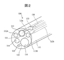
- FIG. 2 is a perspective view showing the structure of the tip portion 104 of the endoscope 100.
- the endoscope system 1 is roughly composed of an endoscope 100, a processor 200, a light source device 300, a water supply / air supply unit 400, a suction unit 500, a display 600, and an input unit 700.
- the endoscope 100 is configured to be insertable into the body of a subject, images a subject, and has a function of transmitting an image signal of the captured image to a processor 200.
- the processor 200 receives the image signal from the endoscope 100 and executes a predetermined signal processing.
- the light source device 300 is configured to be connectable to the processor 200, and includes a light source that emits irradiation light for illuminating the subject inside the light source device 300.
- the light from the light source is directed toward the subject via the light guide described later.
- the light source device 300 may be configured separately from the processor 200 so as to be connectable to the processor 200, or may be incorporated inside the processor 200.
- the water supply / air supply unit 400 includes a water flow supplied to the subject, an air pump for discharging the air flow, and a water flow pump (not shown).
- the suction unit 500 includes a pump and a tank (not shown) for sucking the body fluid or excised material sucked from the body of the subject through the insertion unit 101.
- the display 600 is a display device for displaying based on, for example, a data processing result in the processor 200.
- the input unit 700 is a device for inputting instructions from the operator in various measurement operations.
- the endoscope 100 includes an insertion portion 10, a hand operation portion 102, a universal cable 105, and a connector portion 106.
- the insertion portion 10 further includes a flexible tube portion 101, a connection portion 103A, a curved portion 103, and a tip portion 104.
- the insertion portion 10 of the endoscope 100 has flexibility and includes a flexible tube portion 101 for inserting into the body of the subject.
- the flexible pipe portion 101 is connected to the hand operation portion 102 at one end thereof.
- the hand operation unit 102 includes, for example, a bending operation knob 102A and other operation units that can be operated by the user, and is a part for causing the operator to perform various operations for imaging by the endoscope system 1.
- the hand operation unit 102 is provided with a treatment tool insertion port 102B for inserting the treatment tool.
- the portion close to the curved portion 103 is the first flexible tube portion 101A
- the portion close to the hand operation portion 102 is the second flexible tube portion 101B.
- the shape of the curved portion 103 can be actively changed by the operation of the bending operation knob 102A, whereas the first flexible tube portion 101A is irrelevant to the operation of the bending operation knob 102A.
- This is a portion whose shape is passively changed by an external force, for example, an external force caused by the tip portion 104 or the curved portion 103 hitting the wall surface of the digestive organ.
- the second flexible tube portion 101B but the degree of change in shape is smaller than that of the first flexible tube portion 101A (the maximum radius of curvature is large).
- the flexible tube portion 101 has two types of flexible tube portions, but the present invention is not limited to this, and three or more types of flexible tube portions are provided. It may be good, or one type may be used.
- a bending portion 103 (active bending portion) configured to be bendable is provided at the tip of the flexible pipe portion 101. As described above, the bending portion 103 is bent by the traction of the operation wire (not shown in FIG. 1) linked to the rotation operation of the bending operation knob 102A provided on the hand operation portion 102. A connecting portion that is not deformed by the bending wire W or an external force may be provided between the bending portion 103 and the first flexible pipe portion 101A.
- a tip portion 104 provided with an image sensor (imaging unit) is connected to the tip of the curved portion 103.
- the imaging region of the endoscope 100 can be changed by changing the direction of the tip portion 104 according to the bending operation of the bending portion 103 by the rotation operation of the bending operation knob 102A.
- the universal cable 105 extends toward the connector unit 106.
- the universal cable 105 includes a light guide, various wirings, and various tubes inside.
- the connector unit 106 includes various connectors for connecting the endoscope 100 to the processor 200. Further, the connector portion 106 includes a water supply / air supply tube 108 as a path for sending the water flow and the air flow toward the insertion portion 10.
- Light distribution lenses 112A and 112B are arranged at the tip portion 104 of the endoscope 100, and light guides LGa and LGb extend from the tip portion 104 to the connector portion 106 inside the flexible tube portion 101. There is.
- the light from the light source of the light source device 300 is guided by the light guides LGa and LGb, and is irradiated toward the subject by the light distribution lenses 112A and 112B arranged at the tip portion 104.
- the endoscope 100 includes an objective lens 113 and an image pickup device 133 at the tip portion 104.
- the objective lens 113 provided at the tip portion 104 collects scattered light and reflected light from the subject to form an image of the subject on the light receiving surface of the image sensor 133.
- the image sensor 133 may be composed of a CCD (Charge Coupled Device) or a CMOS sensor (Complementary Metal Oxide Semiconductor Sensor) as an example.
- the image sensor 133 is controlled by signals (gain control signal, exposure control signal, shutter speed control signal, etc.) supplied from the processor 200 via the electrical wiring 138, and is an image of the image captured by the processor 200.
- the signal is supplied via the electrical wiring 138 and the A / D conversion circuit (not shown).
- an air supply water supply port 114 is provided on the end surface of the tip portion 104 as end portions or openings of various tubes.
- the air supply water supply port 114 (nozzle) is connected to the air supply water supply tube 121 in order to introduce a water flow or an air flow for cleaning the tip portion 104 or the like.
- the sub water supply port 115 is connected to the sub water supply tube 122 in order to introduce the sub water supply for removing filth in the field of view.
- the tubes 121 to 122 are arranged so as to extend along the inside of the tip portion 104, the curved portion 103, the flexible tube portion 101, the hand operation portion 102, and the universal cable 105.
- a treatment tool tube 141 is provided inside the endoscope 100.
- the treatment tool tube 141 is arranged with a treatment tool such as forceps so as to be able to move forward and backward.
- the tip of the treatment tool tube 141 constitutes the treatment tool mouth 116 at the tip portion 104.
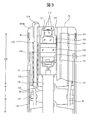
- the cross-sectional structure of the tip portion 104 will be described in more detail with reference to FIG.
- This cross-sectional view shows the details of the structures of the objective lens 113 to the electrical wiring 138, the air supply / water supply tube 121, and the treatment tool tube 141.
- the structures of the light distribution lenses 112A and 112B and the light guides LGa and LGb are not shown. Further, the structure of the secondary water supply tube 122 is also not shown.
- the tip portion 104 has a tip hard portion 104M.
- the hard tip portion 104M includes a hole portion constituting the above-mentioned air supply water supply port 114, secondary water supply port 115, and treatment tool port 116. As shown in FIG. 3, the air supply / water supply tube 121 and the treatment tool tube 141 are inserted into the corresponding holes of the tip rigid portion 104M.
- the hard tip portion 104M also has a hole for fitting the lens frame 136 that holds the objective lens 113, the aperture AP, and the light-shielding mask 131.
- the lens frame 136 is fixed to the hole of the hard tip portion 104M via the sealing agent 137.
- a light-shielding mask 131 for example, a light-shielding mask 131, a cover glass 132, an image sensor (CCD) 133, and a circuit board 134 are held by a CCD unit frame 135, and the CCD unit frame 135 is a hard tip portion. It is inserted and fixed in the hole of 104M. An electric wiring 138 is connected to the circuit board 134.
- the tip portion 104 (tip hard portion 104M) configured as described above is fitted into the tip of the curved portion 103.
- the curved portion 103 is configured by rotatably connecting curved pieces 153 formed in a substantially cylindrical shape to each other with rivets.
- the outer surface of the curved piece 153 is covered with a mesh tube 152.
- the reticulated pipe 152 is joined to the tip rigid portion 104M via the ring contact pipe 151 at its end.
- the outer surface of the net-like tube 152 is covered with an outer skin rubber tube 155 made of synthetic resin.
- the outer skin rubber tube 155 and the tip rigid portion l04M are fixed at their ends by, for example, a fixing thread S1.
- a wire guide 154 is provided between the plurality of bending pieces 153, and the bending wire W for the bending operation penetrates through the wire guide 154.
- Four bending wires W are provided in one flexible tube portion 101, for example, at substantially equal intervals in the circumferential direction.
- One end of each bending wire W is fixed to the frontmost bending piece 153.
- the other end of the bending wire W is tensioned and relaxed by the operation of the bending operation knob 102A, so that the bending portion 103 is curved.
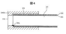
- FIG. 4 is a cross-sectional view showing an example of the structure of the treatment tool tube 141 according to the comparative example
- FIG. 5 is a cross-sectional view showing an example of the structure of the treatment tool tube 141 according to the first embodiment.
- the treatment tool tube 141 of the comparative example of FIG. 4 has a two-layer structure of an inner layer 201 and an outer layer 202 thereof.
- the inner layer 201 is made of polytetrafluoroethylene (PTFE) having a solid structure over the entire length (tip part 204 to the hand operating part 102), and the outer layer 202 is made of polytetrafluoroethylene having a porous structure over the entire length. It is composed of fluoroethylene (PTFE) as a material.
- the treatment tool tube 141 is inserted into a hole formed in the tip rigid portion 104M so as to have a size corresponding to the outer diameter of the treatment tool tube 141.
- An adhesive 139 is applied between the outer surface of the treatment tool tube 141 and the inner wall of the hole, and the treatment tool tube 141 is fixed to the hard tip portion 104M by the adhesive 139.
- the treatment tool tube 141 having a two-layer structure of a solid structure PTFE and a porous structure PTFE is inserted into the hole of the tip hard portion 104M of the tip portion 104 and fixed with the adhesive 139, the treatment tool tube The 141 can be fixed without deforming its outer shape. Further, since the outer layer 202 is made of PTFE having a porous structure over the entire length, the flexibility of the tube can be ensured.
- the adhesive 139 needs to be applied to the end of the treatment tool tube 141 in order to prevent air leakage from the end of the treatment tool tube 141. Therefore, it is difficult to avoid such protrusion of the adhesive 139A.
- the outer layer 202 of the treatment tool tube 141 of the first embodiment has a two-layer structure of an inner layer 201 and an outer layer 202 thereof, as in the comparative example.
- the inner layer 201 is made of PTFE having a solid structure over the entire length as a material, as in the comparative example.
- the first portion 202A located at the end of the treatment tool tube 141 is composed of a solid structure of PTFE as a material.
- the remaining second portion 202B is made of PTFE having a porous structure as a material.
- both the inner layer 201 and the outer layer 202 are made of solid PTFE.
- the outer layer 202 at the end of the treatment tool tube 141 is made of a solid structure of PTFE as the inner layer 201. Therefore, even if the inner layer 201 at the end is scratched in the step of removing the adhesive 139A, air leakage does not occur because the outer layer 202 is a solid structure of PTFE.
- the outer layer 202 (second part 202B) excluding the end portion is made of PTFE having a porous structure as in the comparative example.
- the flexibility of the treatment tool tube 141 can be increased, and the flexible tube portion 101 can be flexibly deformed according to the shape of the digestive organ.
- the adhesive strength of the adhesive 139 can be increased by the anchor effect, which makes it possible to firmly connect the treatment tool tube 141 and the hard tip portion 104M.
- an endoscope capable of ensuring the flexibility of the tube while preventing deformation of the tube and occurrence of air leakage and the like can be provided. Can be provided.
- the structure of the treatment tool tube 141 is different from that of the first embodiment in this second embodiment.
- the treatment tool tube 141 includes a first portion 202A made of solid-structured PTFE as a material and a second portion 202B made of porous PTFE as a material, as in the first embodiment. ing.
- a third portion 20C (transition portion) is provided between the first portion 202A and the second portion 202B, which increases as the porosity approaches the second portion 202B.
- the third portion 202C extends from the inside of the tip rigid portion 104M to the vicinity of the entrance of the hole portion of the tip rigid portion 104M.
- the porosity of the third portion 202C is substantially zero in the vicinity of the first portion 202A, but the porosity increases as it approaches the second portion 202B, and in the vicinity of the second portion 202B, the porosity of the second portion 202B It is almost the same as the porosity.
- the third portion 202C is provided with PTFE having a porous structure at least in a part thereof, an anchor effect is generated by the adhesive 139, and the adhesive 139 can be firmly connected to the tip hard portion 104M. ..
- the second embodiment can also produce substantially the same effect as the first embodiment.
- the outer layer 202 of the treatment tool tube 141 has a first portion 202A made of solid-structured PTFE as a material and a second portion made of porous PTFE as a material, as in the first embodiment. It is equipped with 202B2.
- the outer layer 202 located inside the hole of the tip rigid portion 104M has a first portion 202A, a fourth portion 202B1 made of a porous PTFE as a material, and a solid structure PTFE in order from the tip 104 side. Includes a fifth portion 202D made of.
- the fifth portion 202D is provided before and after the hole portion of the tip rigid portion 104M, and a part of the fifth portion 202D projects outward from the hole portion.
- a sixth portion 202C1 in which the porosity gradually increases is also formed between the fifth portion 202D and the second portion 202B2.
- the sixth portion 202C1 may be omitted, and the structure may be such that the fifth portion 202D of the solid structure and the second portion of the porous structure are directly connected.
- the same effect as that of the first embodiment can be obtained by forming the first portion 202A using PTFE having a solid structure as a material. Further, the treatment tool tube 141 can be firmly connected to the hard tip portion 104M by the fourth portion 202B1 formed of PTFE having a porous structure as a material.
- the fifth portion 202D made of a solid structure PTFE is formed so as to protrude from the hole before and after the hole, so that the treatment tool tube 141 can be formed. Even if bending stress is applied, the possibility of buckling or the like can be reduced.
- the treatment tool tube 141 is less likely to bend at the root of the hole portion. As shown in FIG. 8, when the outer layer 202 before and after the entrance of the hole is the second portion 202B2 made of a porous PTFE material, the treatment tool tube 141 tends to bend from the root of the hole. .. If the forceps F entering and exiting the treatment tool tube 141 come into contact with the bent portion, the inner layer 201 may be damaged. On the other hand, in the fifth embodiment, by providing the fifth portion 202D before and after the hole portion, the treatment tool tube 141 is less likely to bend at the root, and damage to the treatment tool tube 141 can be suppressed. ..
- the present invention is not limited to the above-described examples, and includes various modifications.
- the above-described embodiment has been described in detail in order to explain the present invention in an easy-to-understand manner, and is not necessarily limited to the one including all the described configurations.
- it is possible to replace a part of the configuration of one embodiment with the configuration of another embodiment and it is also possible to add the configuration of another embodiment to the configuration of one embodiment.
Landscapes
- Health & Medical Sciences (AREA)
- Life Sciences & Earth Sciences (AREA)
- Surgery (AREA)
- Physics & Mathematics (AREA)
- Engineering & Computer Science (AREA)
- Medical Informatics (AREA)
- Animal Behavior & Ethology (AREA)
- Veterinary Medicine (AREA)
- Public Health (AREA)
- General Health & Medical Sciences (AREA)
- Biomedical Technology (AREA)
- Heart & Thoracic Surgery (AREA)
- Biophysics (AREA)
- Molecular Biology (AREA)
- Pathology (AREA)
- Optics & Photonics (AREA)
- Nuclear Medicine, Radiotherapy & Molecular Imaging (AREA)
- Radiology & Medical Imaging (AREA)
- Astronomy & Astrophysics (AREA)
- General Physics & Mathematics (AREA)
- Human Computer Interaction (AREA)
- Manufacturing & Machinery (AREA)
- Endoscopes (AREA)
- Instruments For Viewing The Inside Of Hollow Bodies (AREA)
Abstract
チューブの変形や空気漏れの発生等を防止しつつも、チューブの柔軟性を確保する。この内視鏡は、挿入部と、前記挿入部の内部に配置されるチューブとを備える。前記挿入部は、操作に基づき湾曲可能な湾曲部と、前記湾曲部の先端に接続される先端部と、前記操作とは無関係な外力により湾曲可能な可撓管部とを含む。前記チューブは、内層と、前記内層の外側に形成される外層とを備える。前記内層は、充実構造のポリテトラフルオロエチレンで形成される。前記外層は、前記先端部の側の端部に位置し、充実構造のポリテトラフルオロエチレンで形成される第1部分と、多孔質構造のポリテトラフルオロエチレンで形成される第2部分とを備える。
Description
本発明は、内視鏡に関する。
内視鏡装置は一般に、被検者の体内(消化器官など)に挿入される挿入部を有している。挿入部は、光を伝達するためのライトガイド、及び撮像部からの電気信号を伝達するための電気配線をその内部に有している。これに加え、挿入部は、送水又は送気のための送気送水用チューブや、処置具を挿脱するための処置具用チューブをその内部に有している。
このようなチューブを内視鏡の先端部に接続する場合、チューブの強度が低下したり、外形が変化したり、又は内面に段差ができたりすることがないように接続を行うことが望まれる。また、チューブの破損等により空気漏れを生じさせないことも求められる。その一方で、各種チューブは柔軟に変形可能とされることが望まれる。
従来提案されている内視鏡では、各種チューブにおいて上記の要望を満足することは困難であった。例えば、特許文献1では、パイプ部材に外側からチューブを嵌入させる構造を採用しているため、チューブの外径がパイプ部材への接続部分(端部)において大きくなると共に、チューブが変形するため、変形部分の物理的強度が低下するという問題がある。
一方、特許文献2は、同様にパイプ部材に対し外側からチューブを嵌入させる構造において、チューブを二層構造とし、内層は充実構造のポリテトラフルオロエチレン(PTFE)を材料として構成し、外層のうち接続部分となる端部は多孔質構造のポリテトラフルオロエチレン(PTFE)を材料として構成している。端部が多孔質構造とされていることから、パイプ部材への嵌入の際、より小さな力で嵌入動作を行うことができる。しかし、この構造においても、チューブの外径の変化は不可避であり、物理的強度が低下するという問題は依然として生ずる。
本発明は、チューブの変形や空気漏れの発生等を防止しつつも、チューブの柔軟性を確保することができる内視鏡を提供することを目的とする。
上記の課題を解決するため、本発明に係る内視鏡は、挿入部と、前記挿入部の内部に配置されるチューブとを備える。前記挿入部は、操作に基づき湾曲可能な湾曲部と、前記湾曲部の先端に接続される先端部と、前記操作とは無関係な外力により湾曲可能な可撓管部とを含み、前記チューブは、内層と、前記内層の外側に形成される外層とを備える。前記内層は、充実構造のポリテトラフルオロエチレンで形成され、前記外層は、前記先端部の側の端部に位置し、充実構造のポリテトラフルオロエチレンで形成される第1部分と、多孔質構造のポリテトラフルオロエチレンで形成される第2部分とを備える。
本発明の内視鏡によれば、チューブの変形や空気漏れの発生等を防止しつつも、チューブの柔軟性を確保することができる内視鏡を提供することができる。
以下、添付図面を参照して本実施形態について説明する。添付図面では、機能的に同じ要素は同じ番号で表示される場合もある。なお、添付図面は本開示の原理に則った実施形態と実装例を示しているが、これらは本開示の理解のためのものであり、決して本開示を限定的に解釈するために用いられるものではない。本明細書の記述は典型的な例示に過ぎず、本開示の特許請求の範囲又は適用例を如何なる意味においても限定するものではない。
本実施形態では、当業者が本開示を実施するのに十分詳細にその説明がなされているが、他の実装・形態も可能で、本開示の技術的思想の範囲と精神を逸脱することなく構成・構造の変更や多様な要素の置き換えが可能であることを理解する必要がある。従って、以降の記述をこれに限定して解釈してはならない。
[第1の実施の形態]
まず、本発明の第1の実施の形態の内視鏡システムについて詳細に説明する。図1は、第1の実施形態の内視鏡システム1の外観図であり、図2は、内視鏡100の先端部104の構造を示す斜視図である。内視鏡システム1は、内視鏡100、プロセッサ200、光源装置300、送水送気部400、吸引部500、ディスプレイ600、及び入力部700から大略構成される。
まず、本発明の第1の実施の形態の内視鏡システムについて詳細に説明する。図1は、第1の実施形態の内視鏡システム1の外観図であり、図2は、内視鏡100の先端部104の構造を示す斜視図である。内視鏡システム1は、内視鏡100、プロセッサ200、光源装置300、送水送気部400、吸引部500、ディスプレイ600、及び入力部700から大略構成される。
内視鏡100は、被検体の体内に挿入可能に構成されて被写体を撮像し、その撮像された画像の画像信号をプロセッサ200に伝送する機能を有する。プロセッサ200は、内視鏡100からの画像信号を受信して所定の信号処理を実行する。
光源装置300は、プロセッサ200と接続可能に構成され、その内部に被写体を照射するための照射光を発する光源を備えている。光源からの光は、後述するライトガイドを介して被検体に向けて照射される。光源装置300は、プロセッサ200とは別体として構成されてプロセッサ200と接続可能に構成されてもよいし、プロセッサ200の内部に組み込まれていてもよい。
送水送気部400は、被検体に対して供給される水流、又は空気流を放出するためのエアポンプ、及び水流ポンプ(図示せず)を備えている。吸引部500は、挿入部101を介して被検者の体内から吸引された体液や切除物を吸引するためのポンプ及びタンク(図示せず)を備えている。
ディスプレイ600は、例えばプロセッサ200でのデータ処理結果等に基づく表示を行うための表示装置である。また、入力部700は、各種測定動作におけるオペレータからの指示を入力するための装置である。
内視鏡100は、挿入部10と、手元操作部102と、ユニバーサルケーブル105と、コネクタ部106とを備えている。挿入部10は更に、可撓管部101と、接続部103Aと、湾曲部103と、先端部104とを備えている。
内視鏡100の挿入部10は、図1に示すように、可撓性を有し、被検体の体内に挿入するための可撓管部101を備えている。可撓管部101は、その一端において手元操作部102と接続されている。手元操作部102は、例えば湾曲操作ノブ102A、その他ユーザによって操作可能な操作部を備えており、内視鏡システム1による撮像のための各種操作をオペレータに行わせるための部分である。なお、手元操作部102には、処置具を挿入させるための処置具挿入口102Bが設けられている。
可撓管部101のうち、湾曲部103に近い部分は、第1可撓管部101Aであり、手元操作部102に近い部分は、第2可撓管部101Bである。湾曲部103が、湾曲操作ノブ102Aのオペレータによる操作により能動的にその形状が変化可能にされているのに対し、この第1可撓管部101Aは、湾曲操作ノブ102Aの操作とは無関係な外力、例えば先端部104や湾曲部103が消化器官の壁面に当たることによる外力により、受動的にその形状が変化する部分である。第2可撓管部101Bも同様であるが、形状の変化の度合が第1可撓管部101Aに比べ小さい(最大曲率半径が大きい)。なお、図1の例では、可撓管部101が2種類の可撓管部を有しているが、これに限定されるものではなく、3種類以上の可撓管部が備えられていても良いし、1種類でも構わない。
可撓管部101の先端には、湾曲可能に構成された湾曲部103(能動湾曲部)が設けられている。前述のように、手元操作部102に設けられた湾曲操作ノブ102Aの回転操作に連動した操作ワイヤ(図1では図示せず)の牽引によって湾曲部103は湾曲する。なお、湾曲部103と第1可撓管部101Aとの間には、湾曲用ワイヤWや外力により変形しない接続部が設けられていてもよい。
更に、湾曲部103の先端には、撮像素子(撮像部)を備えた先端部104が連結されている。湾曲操作ノブ102Aの回転操作による湾曲部103の湾曲動作に応じて先端部104の向きが変わることにより、内視鏡100による撮影領域を変化させることができる。
手元操作部102の反対側からは、コネクタ部106に向けてユニバーサルケーブル105が延びている。ユニバーサルケーブル105は、挿入部10と同様に、その内部にライトガイド、各種配線、各種チューブを含んでいる。
コネクタ部106は、内視鏡100をプロセッサ200に接続させるための各種コネクタを含んでいる。また、コネクタ部106は、水流及び空気流を挿入部10に向けて送るための経路としての送水送気用チューブ108を含む。
図2を参照して、内視鏡100の先端部104の構造を説明する。内視鏡100の先端部104には、配光レンズ112A、112Bが配置され、可撓管部101の内部には、先端部104からコネクタ部106に亘って、ライトガイドLGa、LGbが延びている。光源装置300の光源からの光が、このライトガイドLGa、LGbにより導光され、先端部104に配置された配光レンズ112A、112Bにより、被検体に向けて照射される。
また、内視鏡100は、図2に示すように、先端部104において対物レンズ113と撮像素子133を備えている。先端部104に設けられる対物レンズ113は、被検体からの散乱光や反射光を集光して、撮像素子133の受光面上に被検体の像を結像させる。
撮像素子133は、一例としてCCD(Charge Coupled Device)、又はCMOSセンサ(Complementary Metal Oxide Semiconductor Sensor)により構成され得る。撮像素子133は、プロセッサ200から電気配線138を介して供給される信号(ゲインコントロール信号、露出制御信号、シャッタ速度制御信号など)により制御されるとともに、プロセッサ200に対し、撮像された画像の画像信号を電気配線138及びA/D変換回路(図示せず)を介して供給するようにされている。
また、先端部104の端面には、各種チューブの端部又は開口として、送気送水口114、副送水口115、及び処置具口116が設けられている。送気送水口114(ノズル)は、先端部104の洗浄等のための水流、又は空気流を導入するため、送気送水チューブ121に接続されている。
また、副送水口115は、視野内の汚物除去のための副送水を導入するため、副送水チューブ122に接続されている。チューブ121~122は、先端部104、湾曲部103、可撓管部101、手元操作部102、及びユニバーサルケーブル105の内部に沿って延びるように配置されている。
このようなチューブ121~122に加え、内視鏡100の内部には、処置具チューブ141が設けられている。処置具チューブ141は、鉗子等の処置具をその内部に進退自在に配置されている。処置具チューブ141の先端は、先端部104において処置具口116を構成している。
図3を参照して、先端部104の断面構造をより詳細に説明する。この断面図では、対物レンズ113~電気配線138、送気送水チューブ121、及び処置具チューブ141の構造の詳細を示している。配光レンズ112A、112B及びライトガイドLGa、LGbの構造については図示を省略している。また、副送水チューブ122の構造も図示を省略している。
先端部104は、先端硬質部104Mを有している。先端硬質部104Mは、前述の送気送水口114、副送水口115、及び処置具口116を構成する孔部を備えている。図3に示すように、送気送水チューブ121、及び処置具チューブ141が、先端硬質部104Mの対応する孔部に挿入されている。
先端硬質部104Mは、対物レンズ113、絞りAP、遮光マスク131を保持するレンズ枠136を嵌入するための孔部も有している。レンズ枠136は、密封剤137を介して先端硬質部104Mの孔部に固定される。
一方、対物レンズ113の後方には、一例として、遮光マスク131、カバーガラス132、撮像素子(CCD)133、及び回路基板134がCCDユニット枠135により保持され、このCCDユニット枠135が先端硬質部104Mの孔部に挿入・固定されている。回路基板134には、電気配線138が接続されている。
上記のように構成された先端部104(先端硬質部104M)が、湾曲部103の先端に嵌め込まれる。湾曲部103は、略円筒状に形成された湾曲駒153をリベットで互いに回動可動に接続して構成される。湾曲駒153の外面は網状管152で被覆されている。網状管152は、その端部において接輪管151を介して先端硬質部104Mと接合される。また、網状管152の外面は、合成樹脂製の外皮ゴムチューブ155で覆われている。外皮ゴムチューブ155と先端硬質部l04Mとは、その端部において例えば固定用糸S1により固定される。
複数の湾曲駒153の間には、ワイヤガイド154が設けられ、このワイヤガイド154に、湾曲動作のための湾曲用ワイヤWが貫通している。湾曲用ワイヤWは、1本の可撓管部101内において、例えば周方向に略等間隔に4本設けられる。各湾曲用ワイヤWの一端は最前部の湾曲駒153に固定されている。この湾曲用ワイヤWの他端が湾曲操作ノブ102Aの操作により緊張・弛緩されることにより、湾曲部103が湾曲する。
図4及び図5を参照して、処置具チューブ141の構造の一例を説明する。図4は、比較例に係る処置具チューブ141の構造の一例を示す断面図であり、図5は、第1の実施の形態に係る処置具チューブ141の構造の一例を示す断面図である。
図4の比較例の処置具チューブ141は、内層201と、その外側の外層202との二層構造を有する。そして、内層201は、全長(先端部204~手元操作部102)に亘って充実構造のポリテトラフルオロエチレン(PTFE)を材料として構成され、外層202は、全長に亘って多孔質構造のポリテトラフルオロエチレン(PTFE)を材料として構成される。処置具チューブ141は、先端硬質部104Mにおいて、処置具チューブ141の外径に合わせた大きさに形成された孔部に挿入される。処置具チューブ141の外面と孔部の内壁との間には接着剤139が塗布され、処置具チューブ141は、この接着剤139により先端硬質部104Mに固定される。
このような充実構造のPTFEと多孔質構造のPTFEの二層構造の処置具チューブ141を、先端部104の先端硬質部104Mの孔部に挿入して接着剤139で固定する場合、処置具チューブ141は、その外形を変形することなく固定することができる。また、全長に亘って外層202が多孔質構造のPTFEで構成されるため、チューブの柔軟性も確保することができる。
しかし、図4の比較例の構造の場合、処置具チューブ141の端部において接着剤139Aのはみ出しが生じると、その除去に支障が生じるという問題がある。このような接着剤139Aのはみ出しが生じた場合、工具を用いてこれを除去する必要が生じることがある。ところが、除去の過程で内層201が破損し、外層202が露出してしまうことが生じ得る。この場合、外層202の露出部分から空気漏れが生じる虞がある。
図4の構造の場合、処置具チューブ141の端部からの空気漏れを防ぐため、接着材139は処置具チューブ141の端部にまで塗布される必要がある。このため、このような接着剤139Aのはみ出しを回避することは困難である。
一方、第1の実施の形態の処置具チューブ141の外層202は、比較例と同様に、内層201と、その外側の外層202との二層構造を有する。また、内層201は、比較例と同様に、全長に亘り充実構造のPTFEを材料として構成される。
ただし、外層202に関しては、比較例とは異なり、処置具チューブ141の端部に位置する第1部分202Aが、充実構造のPTFEを材料として構成される。残る第2部分202Bは、多孔質構造のPTFEを材料として構成される。換言すれば、処置具チューブ141の端部においては、内層201及び外層202の両方が充実構造のPTFEで構成される。
この第1の実施の形態の構成によれば、接着剤139Aのはみ出しが生じたとしても、比較例のような空気漏れが生じる虞は無い。処置具チューブ141の端部の外層202が、内層201と同様に充実構造のPTFEを材料として構成される。このため、接着剤139Aを除去する工程において、端部の内層201に傷が生じたとしても、外層202が充実構造のPTFEであるため、空気漏れは生じない。
一方、端部を除く外層202(第2部分202B)は、比較例と同様に多孔質構造のPTFEを材料として構成される。外層202が多孔質構造のPTFEである場合、処置具チューブ141の柔軟性を高めることができ、可撓管部101を消化器官の形状に合わせて柔軟に変形させることができる。また、アンカー効果により接着剤139による接着強度を高くすることができ、これにより、処置具チューブ141と先端硬質部104Mとを強固に接続することが可能になる。
以上説明したように、第1の実施の形態の処置具チューブ141によれば、チューブの変形や空気漏れの発生等を防止しつつも、チューブの柔軟性を確保することができる内視鏡を提供することができる。
[第2の実施の形態]
次に、第2の実施の形態に係る内視鏡システムを、図6を参照して説明する。この第2の実施の形態の内視鏡システムの全体構成は、第1の実施の形態(図1~図3)と略同一であるので、以下では重複する説明は省略する。
次に、第2の実施の形態に係る内視鏡システムを、図6を参照して説明する。この第2の実施の形態の内視鏡システムの全体構成は、第1の実施の形態(図1~図3)と略同一であるので、以下では重複する説明は省略する。
この第2の実施の形態は、図6に示すように、処置具チューブ141の構造が第1の実施の形態と異なっている。この処置具チューブ141は、第1の実施の形態と同様に、充実構造のPTFEを材料として構成される第1部分202Aと、多孔質構造のPTFEを材料として構成される第2部分202Bを備えている。ただし、第1部分202Aと第2部分202Bとの間に、気孔率が第2部分202Bに近付くほど大きくなる第3部分20C(移行部)が設けられている。第3部分202Cは、一例として、先端硬質部104Mの内部から、先端硬質部104Mの孔部の入り口付近まで延びている。
第3部分202Cは、第1部分202Aの近傍では、気孔率が略ゼロであるが、第2部分202Bに近付くほどに気孔率が上昇し、第2部分202Bの近傍では、第2部分202Bの気孔率と略同一となる。このように、第3部分202Cは、少なくとも一部において多孔質構造のPTFEを備えているので、接着剤139によるアンカー効果が生じ、接着剤139により先端硬質部104Mに強固に接続させることができる。
この第2の実施の形態によっても、第1の実施の形態と略同一の効果を生じさせることができる。
[第3の実施の形態]
次に、第3の実施の形態に係る内視鏡システムを、図7を参照して説明する。この第3の実施の形態の内視鏡システムの全体構成は、第1の実施の形態(図1~図3)と略同一であるので、以下では重複する説明は省略する。
次に、第3の実施の形態に係る内視鏡システムを、図7を参照して説明する。この第3の実施の形態の内視鏡システムの全体構成は、第1の実施の形態(図1~図3)と略同一であるので、以下では重複する説明は省略する。
この第3の実施の形態は、図7に示すように、処置具チューブ141の構造が第1の実施の形態と異なっている。この処置具チューブ141の外層202は、第1の実施の形態と同様に、充実構造のPTFEを材料として構成される第1部分202Aと、多孔質構造のPTFEを材料として構成される第2部分202B2を備えている。
ただし、先端硬質部104Mの孔部の内部に位置する外層202は、先端部104側から順に、第1部分202Aと、多孔質構造のPTFEを材料とする第4部分202B1と、充実構造のPTFEを材料とする第5部分202Dとを含む。第5部分202Dは、先端硬質部104Mの孔部の前後に設けられ、第5部分202Dの一部は、当該孔部から外に突出している。
なお、図7に示す例では、第5部分202Dと第2部分202B2との間に、気孔率が徐々に大きくなる第6部分202C1も形成されている。この第6部分202C1は省略し、充実構造の第5部分202Dと、多孔質構造の第2部分が直接接続される構造としてもよい。
第3の実施の形態の構造によれば、第1部分202Aが充実構造のPTFEを材料として形成されることで、第1の実施の形態と同様の効果を得ることができる。また、多孔質構造のPTFEを材料として形成される第4部分202B1により、処置具チューブ141を先端硬質部104Mに対し強固に接続することができる。
更に、この第4部分202B1に隣接して、充実構造のPTFEを材料とする第5部分202Dが、孔部の前後において、孔部から突出するように構成されることで、処置具チューブ141に曲げ応力が加わったとしても、座屈等が生じる虞を小さくすることができる。
また、第5部分202Dが孔部の前後に設けられることで、孔部の根元で処置具チューブ141が曲がりにくくなる。図8に示すように、孔部の入り口の前後の外層202が多孔質構造のPTFEを材料とする第2部分202B2とされている場合、処置具チューブ141は、孔部の根元から曲がりやすくなる。その曲がった部分に、処置具チューブ141内を出入りする鉗子Fが接触すると、内層201に破損が生じる虞がある。これに対し、第5の実施の形態では、孔部の前後に第5部分202Dが設けられることで、処置具チューブ141が根元で曲がりにくくなり、処置具チューブ141の破損を抑制することができる。
[その他]
本発明は上記した実施例に限定されるものではなく、様々な変形例が含まれる。例えば、上記した実施例は本発明を分かりやすく説明するために詳細に説明したものであり、必ずしも説明した全ての構成を備えるものに限定されるものではない。また、ある実施例の構成の一部を他の実施例の構成に置き換えることが可能であり、また、ある実施例の構成に他の実施例の構成を加えることも可能である。また、各実施例の構成の一部について、他の構成の追加・削除・置換をすることが可能である。
本発明は上記した実施例に限定されるものではなく、様々な変形例が含まれる。例えば、上記した実施例は本発明を分かりやすく説明するために詳細に説明したものであり、必ずしも説明した全ての構成を備えるものに限定されるものではない。また、ある実施例の構成の一部を他の実施例の構成に置き換えることが可能であり、また、ある実施例の構成に他の実施例の構成を加えることも可能である。また、各実施例の構成の一部について、他の構成の追加・削除・置換をすることが可能である。
1…内視鏡システム、100…内視鏡、10…挿入部、101…可撓管部、101A…第1可撓管部、101B…第2可撓管部、102…手元操作部、102A…湾曲操作ノブ、103…湾曲部、104…先端部、104M…先端硬質部、105…ユニバーサルケーブル、106…コネクタ部、108…送水送気用チューブ、109…吸引用チューブ、LGa、LGb…ライトガイド、112A、112B…配光レンズ、113…対物レンズ、114…送気送水口、115…副送水口、116…処置具口、121…送気送水チューブ、122…副送水チューブ、141…処置具チューブ、133…撮像素子、134…回路基板、135…CCDユニット枠、136…レンズ枠、137…密封剤、138…電気配線、200…プロセッサ、201…内層、202…外層、300…光源装置、400…送水送気部、500…吸引部、600…ディスプレイ、700…入力部。
Claims (8)
- 挿入部と、
前記挿入部の内部に配置されるチューブと
を備え、
前記挿入部は、
操作に基づき湾曲可能な湾曲部と、
前記湾曲部の先端に接続される先端部と、
前記操作とは無関係な外力により湾曲可能な可撓管部と
を含み、
前記チューブは、内層と、前記内層の外側に形成される外層とを備え、
前記内層は、充実構造のポリテトラフルオロエチレンで形成され、
前記外層は、前記先端部の側の端部に位置し、充実構造のポリテトラフルオロエチレンで形成される第1部分と、多孔質構造のポリテトラフルオロエチレンで形成される第2部分とを備える
ことを特徴とする内視鏡。 - 前記先端部は、前記チューブを挿入可能な孔部を有し、前記チューブは、接着剤により前記先端部に対し固定される、請求項1に記載の内視鏡。
- 前記第2部分は、前記先端部と接する位置に形成されている、請求項1又は2に記載の内視鏡。
- 前記外層は、前記第1部分と前記第2部分の間において、気孔率が前記第2部分に近付くほど大きくなる第3部分を備える、請求項1又は2に記載の内視鏡。
- 前記第3部分は、前記先端部と接する位置に形成されている、請求項4に記載の内視鏡。
- 前記外層は、前記先端部の側の端部から順に、前記第1部分、多孔質構造のポリテトラフルオロエチレンで形成される第4部分、及び充実構造のポリテトラフルオロエチレンで形成される第5部分を備える、請求項1又は2に記載の内視鏡。
- 前記第4部分は、前記先端部と接する位置に形成され、
前記第5部分は、前記先端部の入り口から突出する位置に形成されている、請求項6に記載の内視鏡。 - 前記外層は、前記第5部分と前記第2部分の間において、気孔率が前記第2部分に近付くほど大きくなる第6部分を備える、請求項6に記載の内視鏡。
Priority Applications (4)
| Application Number | Priority Date | Filing Date | Title |
|---|---|---|---|
| ES20873553T ES2979107T3 (es) | 2019-10-10 | 2020-09-30 | Endoscopio |
| EP20873553.0A EP4042926B1 (en) | 2019-10-10 | 2020-09-30 | Endoscope |
| CN202080070696.9A CN114554928B (zh) | 2019-10-10 | 2020-09-30 | 内窥镜 |
| US17/765,678 US12171404B2 (en) | 2019-10-10 | 2020-09-30 | Endoscope |
Applications Claiming Priority (2)
| Application Number | Priority Date | Filing Date | Title |
|---|---|---|---|
| JP2019-187020 | 2019-10-10 | ||
| JP2019187020A JP7364414B2 (ja) | 2019-10-10 | 2019-10-10 | 内視鏡 |
Publications (1)
| Publication Number | Publication Date |
|---|---|
| WO2021070697A1 true WO2021070697A1 (ja) | 2021-04-15 |
Family
ID=75437890
Family Applications (1)
| Application Number | Title | Priority Date | Filing Date |
|---|---|---|---|
| PCT/JP2020/037102 Ceased WO2021070697A1 (ja) | 2019-10-10 | 2020-09-30 | 内視鏡 |
Country Status (6)
| Country | Link |
|---|---|
| US (1) | US12171404B2 (ja) |
| EP (1) | EP4042926B1 (ja) |
| JP (1) | JP7364414B2 (ja) |
| CN (1) | CN114554928B (ja) |
| ES (1) | ES2979107T3 (ja) |
| WO (1) | WO2021070697A1 (ja) |
Citations (5)
| Publication number | Priority date | Publication date | Assignee | Title |
|---|---|---|---|---|
| JPH071630A (ja) | 1992-12-25 | 1995-01-06 | Japan Gore Tex Inc | 可とう性多層チューブ |
| JP2001046314A (ja) * | 1999-08-09 | 2001-02-20 | Olympus Optical Co Ltd | 内視鏡 |
| WO2008088087A2 (en) | 2007-01-18 | 2008-07-24 | Hitachi Koki Co., Ltd. | Power tool |
| WO2016052208A1 (ja) * | 2014-10-03 | 2016-04-07 | オリンパス株式会社 | 挿入機器の挿入部及び挿入機器 |
| US20190246885A1 (en) * | 2016-11-09 | 2019-08-15 | Olympus Corporation | Endoscope |
Family Cites Families (8)
| Publication number | Priority date | Publication date | Assignee | Title |
|---|---|---|---|---|
| US4280500A (en) * | 1978-03-31 | 1981-07-28 | Kazuaki Ono | Tubular flexible medical instrument |
| JPH0143041Y2 (ja) * | 1980-11-19 | 1989-12-14 | ||
| JP3057851B2 (ja) * | 1991-10-08 | 2000-07-04 | 富士写真光機株式会社 | 内視鏡の処置具挿通チャンネル |
| US9439555B2 (en) * | 2005-05-20 | 2016-09-13 | Karl Storz Endovision, Inc. | Liner for endoscope working channel |
| US20100256445A1 (en) | 2006-12-07 | 2010-10-07 | International Polymer Engineering, Inc. | Endoscopic Working Channel and Method of Making Same |
| WO2012005124A1 (ja) | 2010-07-05 | 2012-01-12 | オリンパスメディカルシステムズ株式会社 | 内視鏡装置に配設されるチューブ、および内視鏡装置 |
| WO2014013787A1 (ja) * | 2012-07-19 | 2014-01-23 | オリンパスメディカルシステムズ株式会社 | 内視鏡の挿入部の先端硬質部及び、この先端硬質部を用いた内視鏡 |
| CN111657824B (zh) | 2017-06-01 | 2024-05-10 | Hoya株式会社 | 内窥镜 |
-
2019
- 2019-10-10 JP JP2019187020A patent/JP7364414B2/ja active Active
-
2020
- 2020-09-30 EP EP20873553.0A patent/EP4042926B1/en active Active
- 2020-09-30 CN CN202080070696.9A patent/CN114554928B/zh active Active
- 2020-09-30 WO PCT/JP2020/037102 patent/WO2021070697A1/ja not_active Ceased
- 2020-09-30 ES ES20873553T patent/ES2979107T3/es active Active
- 2020-09-30 US US17/765,678 patent/US12171404B2/en active Active
Patent Citations (5)
| Publication number | Priority date | Publication date | Assignee | Title |
|---|---|---|---|---|
| JPH071630A (ja) | 1992-12-25 | 1995-01-06 | Japan Gore Tex Inc | 可とう性多層チューブ |
| JP2001046314A (ja) * | 1999-08-09 | 2001-02-20 | Olympus Optical Co Ltd | 内視鏡 |
| WO2008088087A2 (en) | 2007-01-18 | 2008-07-24 | Hitachi Koki Co., Ltd. | Power tool |
| WO2016052208A1 (ja) * | 2014-10-03 | 2016-04-07 | オリンパス株式会社 | 挿入機器の挿入部及び挿入機器 |
| US20190246885A1 (en) * | 2016-11-09 | 2019-08-15 | Olympus Corporation | Endoscope |
Non-Patent Citations (1)
| Title |
|---|
| See also references of EP4042926A4 |
Also Published As
| Publication number | Publication date |
|---|---|
| EP4042926A1 (en) | 2022-08-17 |
| CN114554928B (zh) | 2025-12-30 |
| EP4042926B1 (en) | 2024-03-20 |
| JP7364414B2 (ja) | 2023-10-18 |
| EP4042926C0 (en) | 2024-03-20 |
| JP2021061912A (ja) | 2021-04-22 |
| US12171404B2 (en) | 2024-12-24 |
| US20220287585A1 (en) | 2022-09-15 |
| EP4042926A4 (en) | 2023-10-11 |
| ES2979107T3 (es) | 2024-09-24 |
| CN114554928A (zh) | 2022-05-27 |
Similar Documents
| Publication | Publication Date | Title |
|---|---|---|
| JP5390048B1 (ja) | 内視鏡システム | |
| EP2517615B1 (en) | Endoscope apparatus with multiple layer endoscope tube | |
| EP2478822A1 (en) | Endoscope | |
| EP4047409B1 (en) | Endoscope | |
| US11246475B2 (en) | Endoscope | |
| KR101637846B1 (ko) | 내시경 | |
| JP7364414B2 (ja) | 内視鏡 | |
| EP4062820B1 (en) | Endoscope | |
| JPH07308283A (ja) | カバー方式内視鏡 | |
| WO2021100783A1 (ja) | 内視鏡装置 | |
| CN103889306B (zh) | 电子内窥镜装置 | |
| JP5810037B2 (ja) | 内視鏡システム | |
| JP6850694B2 (ja) | 内視鏡及び内視鏡の製造方法 | |
| JP2017074231A (ja) | 超音波内視鏡の製造方法および超音波内視鏡 | |
| JP2025001629A (ja) | 先端構成部、内視鏡挿入部、内視鏡、及び超音波内視鏡 | |
| JP2017225746A (ja) | 内視鏡 | |
| JP2024173018A (ja) | 内視鏡用チューブ及び内視鏡 | |
| CN116687318A (zh) | 内窥镜 | |
| JP2020168092A (ja) | 内視鏡 |
Legal Events
| Date | Code | Title | Description |
|---|---|---|---|
| 121 | Ep: the epo has been informed by wipo that ep was designated in this application |
Ref document number: 20873553 Country of ref document: EP Kind code of ref document: A1 |
|
| NENP | Non-entry into the national phase |
Ref country code: DE |
|
| ENP | Entry into the national phase |
Ref document number: 2020873553 Country of ref document: EP Effective date: 20220510 |