WO2021070795A1 - ローター、ローターの設計方法およびローターの製造方法 - Google Patents
ローター、ローターの設計方法およびローターの製造方法 Download PDFInfo
- Publication number
- WO2021070795A1 WO2021070795A1 PCT/JP2020/037796 JP2020037796W WO2021070795A1 WO 2021070795 A1 WO2021070795 A1 WO 2021070795A1 JP 2020037796 W JP2020037796 W JP 2020037796W WO 2021070795 A1 WO2021070795 A1 WO 2021070795A1
- Authority
- WO
- WIPO (PCT)
- Prior art keywords
- rotor
- yield stress
- adhesive layer
- steel sheet
- laminated core
- Prior art date
- Legal status (The legal status is an assumption and is not a legal conclusion. Google has not performed a legal analysis and makes no representation as to the accuracy of the status listed.)
- Ceased
Links
Images




Classifications
-
- H—ELECTRICITY
- H02—GENERATION; CONVERSION OR DISTRIBUTION OF ELECTRIC POWER
- H02K—DYNAMO-ELECTRIC MACHINES
- H02K1/00—Details of the magnetic circuit
- H02K1/06—Details of the magnetic circuit characterised by the shape, form or construction
- H02K1/22—Rotating parts of the magnetic circuit
- H02K1/27—Rotor cores with permanent magnets
- H02K1/2706—Inner rotors
- H02K1/272—Inner rotors the magnetisation axis of the magnets being perpendicular to the rotor axis
- H02K1/274—Inner rotors the magnetisation axis of the magnets being perpendicular to the rotor axis the rotor consisting of two or more circumferentially positioned magnets
- H02K1/2753—Inner rotors the magnetisation axis of the magnets being perpendicular to the rotor axis the rotor consisting of two or more circumferentially positioned magnets the rotor consisting of magnets or groups of magnets arranged with alternating polarity
- H02K1/276—Magnets embedded in the magnetic core, e.g. interior permanent magnets [IPM]
-
- H—ELECTRICITY
- H02—GENERATION; CONVERSION OR DISTRIBUTION OF ELECTRIC POWER
- H02K—DYNAMO-ELECTRIC MACHINES
- H02K1/00—Details of the magnetic circuit
- H02K1/02—Details of the magnetic circuit characterised by the magnetic material
-
- H—ELECTRICITY
- H02—GENERATION; CONVERSION OR DISTRIBUTION OF ELECTRIC POWER
- H02K—DYNAMO-ELECTRIC MACHINES
- H02K1/00—Details of the magnetic circuit
- H02K1/06—Details of the magnetic circuit characterised by the shape, form or construction
- H02K1/22—Rotating parts of the magnetic circuit
-
- H—ELECTRICITY
- H02—GENERATION; CONVERSION OR DISTRIBUTION OF ELECTRIC POWER
- H02K—DYNAMO-ELECTRIC MACHINES
- H02K15/00—Processes or apparatus specially adapted for manufacturing, assembling, maintaining or repairing of dynamo-electric machines
- H02K15/02—Processes or apparatus specially adapted for manufacturing, assembling, maintaining or repairing of dynamo-electric machines of stator or rotor bodies
- H02K15/03—Processes or apparatus specially adapted for manufacturing, assembling, maintaining or repairing of dynamo-electric machines of stator or rotor bodies having permanent magnets
-
- H—ELECTRICITY
- H02—GENERATION; CONVERSION OR DISTRIBUTION OF ELECTRIC POWER
- H02K—DYNAMO-ELECTRIC MACHINES
- H02K15/00—Processes or apparatus specially adapted for manufacturing, assembling, maintaining or repairing of dynamo-electric machines
- H02K15/12—Impregnating, moulding insulation, heating or drying of windings, stators, rotors or machines
-
- H—ELECTRICITY
- H02—GENERATION; CONVERSION OR DISTRIBUTION OF ELECTRIC POWER
- H02K—DYNAMO-ELECTRIC MACHINES
- H02K21/00—Synchronous motors having permanent magnets; Synchronous generators having permanent magnets
- H02K21/12—Synchronous motors having permanent magnets; Synchronous generators having permanent magnets with stationary armatures and rotating magnets
- H02K21/14—Synchronous motors having permanent magnets; Synchronous generators having permanent magnets with stationary armatures and rotating magnets with magnets rotating within the armatures
-
- H—ELECTRICITY
- H02—GENERATION; CONVERSION OR DISTRIBUTION OF ELECTRIC POWER
- H02K—DYNAMO-ELECTRIC MACHINES
- H02K7/00—Arrangements for handling mechanical energy structurally associated with dynamo-electric machines, e.g. structural association with mechanical driving motors or auxiliary dynamo-electric machines
- H02K7/006—Structural association of a motor or generator with the drive train of a motor vehicle
-
- H—ELECTRICITY
- H02—GENERATION; CONVERSION OR DISTRIBUTION OF ELECTRIC POWER
- H02K—DYNAMO-ELECTRIC MACHINES
- H02K1/00—Details of the magnetic circuit
- H02K1/06—Details of the magnetic circuit characterised by the shape, form or construction
- H02K1/22—Rotating parts of the magnetic circuit
- H02K1/27—Rotor cores with permanent magnets
- H02K1/2706—Inner rotors
- H02K1/272—Inner rotors the magnetisation axis of the magnets being perpendicular to the rotor axis
- H02K1/274—Inner rotors the magnetisation axis of the magnets being perpendicular to the rotor axis the rotor consisting of two or more circumferentially positioned magnets
- H02K1/2753—Inner rotors the magnetisation axis of the magnets being perpendicular to the rotor axis the rotor consisting of two or more circumferentially positioned magnets the rotor consisting of magnets or groups of magnets arranged with alternating polarity
- H02K1/276—Magnets embedded in the magnetic core, e.g. interior permanent magnets [IPM]
- H02K1/2766—Magnets embedded in the magnetic core, e.g. interior permanent magnets [IPM] having a flux concentration effect
-
- H—ELECTRICITY
- H02—GENERATION; CONVERSION OR DISTRIBUTION OF ELECTRIC POWER
- H02K—DYNAMO-ELECTRIC MACHINES
- H02K2213/00—Specific aspects, not otherwise provided for and not covered by codes H02K2201/00 - H02K2211/00
- H02K2213/03—Machines characterised by numerical values, ranges, mathematical expressions or similar information
-
- Y—GENERAL TAGGING OF NEW TECHNOLOGICAL DEVELOPMENTS; GENERAL TAGGING OF CROSS-SECTIONAL TECHNOLOGIES SPANNING OVER SEVERAL SECTIONS OF THE IPC; TECHNICAL SUBJECTS COVERED BY FORMER USPC CROSS-REFERENCE ART COLLECTIONS [XRACs] AND DIGESTS
- Y02—TECHNOLOGIES OR APPLICATIONS FOR MITIGATION OR ADAPTATION AGAINST CLIMATE CHANGE
- Y02T—CLIMATE CHANGE MITIGATION TECHNOLOGIES RELATED TO TRANSPORTATION
- Y02T10/00—Road transport of goods or passengers
- Y02T10/60—Other road transportation technologies with climate change mitigation effect
- Y02T10/64—Electric machine technologies in electromobility
-
- Y—GENERAL TAGGING OF NEW TECHNOLOGICAL DEVELOPMENTS; GENERAL TAGGING OF CROSS-SECTIONAL TECHNOLOGIES SPANNING OVER SEVERAL SECTIONS OF THE IPC; TECHNICAL SUBJECTS COVERED BY FORMER USPC CROSS-REFERENCE ART COLLECTIONS [XRACs] AND DIGESTS
- Y10—TECHNICAL SUBJECTS COVERED BY FORMER USPC
- Y10T—TECHNICAL SUBJECTS COVERED BY FORMER US CLASSIFICATION
- Y10T29/00—Metal working
- Y10T29/49—Method of mechanical manufacture
- Y10T29/49002—Electrical device making
- Y10T29/49009—Dynamoelectric machine
Definitions
- the present invention relates to a rotor, a rotor design method, and a rotor manufacturing method.
- the present application claims priority based on Japanese Patent Application No. 2019-185110 filed in Japan on October 8, 2019, the contents of which are incorporated herein by reference.
- the rotor is a core used as a rotating body in a motor.
- Rotors have so far been manufactured primarily by caulking structures.
- a manufacturing method using (1) an adhesive structure and (2) a combination structure of caulking and adhesive has been proposed (see, for example, Patent Document 1). ..
- IPM motors are the mainstream motors used in automobiles.
- magnets are embedded in the rotor. From the viewpoint of motor efficiency, it is required to install a magnet at a position closer to the outermost circumference. Therefore, stress is concentrated on a narrow steel plate width portion called a bridge on the outside of the magnet, and the rotor is deformed as the bridge tries to expand. Deformation of the rotor means that it becomes impossible to maintain a narrow gap with the stator, which leads to damage to the motor.
- An object of the present invention is to provide a rotor in which damage at high speed rotation is suppressed.
- the rotor according to the present invention is a magnet-embedded rotor incorporated in a motor for traveling of an automobile, and has a laminated core having steel plates laminated to each other and an adhesive layer for adhering the steel plates adjacent to each other in the laminating direction, and the above.
- a magnet embedded in the laminated core is provided, and when the rotor rotates at 11000 rpm, the maximum displacement amount of the outer edge of the laminated core in the radial direction of the rotor is 0.1 mm or less.
- the maximum displacement of the outer edge of the laminated core in the radial direction of the rotor is 0.1 mm or less. Therefore, even when the rotor rotates at the maximum rotation speed (for example, a rotation speed exceeding 11000 rpm) when the automobile is running, deformation of the outer shape of the rotor is suppressed, for example, the rotor comes into contact with the stator, and the like. Can be prevented. As a result, damage to the motor can be suppressed.
- the maximum amount of displacement of the outer edge of the laminated core in the radial direction can be obtained by, for example, the following methods (1) and (2).
- the amount of change in the radial position before and after rotation is calculated for each position along the circumferential direction of the rotor, and the amount of change is added to the amount of elastic deformation during rotation.
- the maximum value is defined as the maximum displacement amount.
- Yield stress YP R of the steel sheet may be more 150 MPa 580 MPa or less.
- the magnet is arranged in a through hole penetrating the laminated core in the laminating direction, and a sealing resin for sealing between the outer surface of the magnet and the inner surface of the through hole is provided in the through hole. It may be.
- the method for designing a rotor according to the present invention is a method for designing a magnet-embedded rotor incorporated in a motor for traveling of an automobile, in which the rotor is bonded to steel plates laminated to each other and steel plates adjacent to each other in the stacking direction.
- a laminated core having an adhesive layer and a magnet embedded in the laminated core are provided, and in the design method, when the rotor rotates at the maximum rotation speed during traveling of the automobile, the rotor is radially oriented.
- the yield stress of the steel sheet and the yield stress of the adhesive layer are set so that the maximum displacement of the outer edge of the laminated core toward the steel sheet is 0.1 mm or less.
- the maximum displacement amount of the outer edge of the laminated core in the radial direction of the rotor is 0.1 mm or less. .. Therefore, even when the rotor rotates at the maximum rotation speed during traveling of the automobile, it is possible to suppress the deformation of the outer shape of the rotor and prevent the rotor from coming into contact with the stator, for example. As a result, damage to the motor can be suppressed.
- the yield stress of the steel sheet and (2) the yield stress of the adhesive layer are set so that the deformation of the steel sheet is regulated when the rotor rotates at the maximum rotation speed when the automobile is running. To do. That is, not only the yield stress of the steel sheet but also the yield stress of the adhesive layer is considered. As a result, even when the yield stress of the steel sheet is low to some extent, the deformation of the steel sheet can be regulated by increasing the yield stress of the adhesive layer. This is because the adhesive layer can suppress the deformation of the steel sheet by partially guaranteeing the function of suppressing the deformation of the steel sheet.
- the strength of the adhesive has a positive correlation with the cost, and the higher the strength of the adhesive, the higher the curing temperature is required.
- the optimum combination of the steel sheet and the adhesive is selected according to not only the cost but also the regional characteristics and marketability. be able to. Therefore, it is possible to manufacture a rotor that meets not only quality requirements but also manufacturing requirements.
- the invention of the present application is used, the above-mentioned manufacturing is difficult, the supply suppliers are limited, a high-strength steel sheet that is costly is not used, and a special steel sheet hardening treatment or heat treatment is performed on a fine part of the rotor. Deformation of the steel sheet can be suppressed without increasing the number of steps for strengthening the steel sheet.
- the yield stress of the steel sheet and YP R (MPa), the yield stress of the adhesive layer and YP B (MPa), when the maximum rotation number of the omega (rpm), the so as to satisfy the following formula (1) the yield stress YP B yield stress YP R and the adhesive layer of the steel sheet may be set.
- A 0.105
- B 17,000
- C 17,000
- D 410
- E 30.
- the rotor manufacturing method according to the present invention uses the rotor design method.
- FIG. 5 is a cross-sectional view taken along the line AA shown in FIG.
- FIG. 5 is a cross-sectional view taken along the line BB shown in FIG.
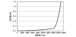
- It is a graph which shows the relationship between the rotation speed of a rotor and the displacement amount of the outer edge of a laminated core.
- It is a top view which shows the analysis result of the Mises stress distribution of a steel sheet when the rotation speed of a rotor is 14000 rpm.
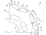
- the rotor 10 is incorporated in a motor for traveling an automobile (for example, a hybrid automobile or an electric automobile).
- the motor is an inner rotor type IPM motor (embedded magnet 30 type motor).
- the rotor 10 is a magnet embedded type.
- the maximum number of revolutions of the motor is determined according to the performance characteristics required for the automobile, and tends to be high when the maximum speed, acceleration, or miniaturization of the motor is emphasized.
- the maximum rotation speed is, for example, 11000 rpm or more, more specifically 12000 rpm or more and 20000 rpm or less.
- the axial direction of the rotor 10 (the direction of the central axis O of the rotor 10) is referred to as the axial direction
- the radial direction of the rotor 10 (the direction orthogonal to the central axis O of the rotor 10) is referred to as the radial direction
- the direction (the direction that orbits around the central axis O of the rotor 10) is called the circumferential direction.
- the rotor 10 includes a laminated core 20, a magnet 30, and a sealing resin 40.
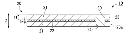
- the laminated core 20 includes a steel plate 21 laminated to each other and an adhesive layer 22 for adhering the adjacent steel plates 21 in the laminating direction Z.
- the stacking direction Z coincides with the axial direction.
- the steel plates 21 adjacent to each other in the stacking direction Z are not fixed by means different from the adhesive layer 22 (for example, caulking). These steel plates 21 are fixed only by the adhesive layer 22.
- the steel plate 21 is an electromagnetic steel plate.
- the steel plate 21 is formed, for example, by punching an electromagnetic steel plate.
- a known electrical steel sheet can be used.
- the chemical composition of the electrical steel sheet is not particularly limited.
- a non-oriented electrical steel sheet is used as the electrical steel sheet.
- a non-oriented electrical steel sheet for example, a non-oriented electrical steel strip of JISC2552: 2014 can be adopted.
- the adhesive layer 22 is an adhesive cured between the steel plates 21 adjacent to each other in the stacking direction Z.
- a thermosetting adhesive by polymerization bonding is used.
- the composition of the adhesive (1) an acrylic resin, (2) an epoxy resin, (3) a composition containing an acrylic resin and an epoxy resin, and the like can be applied.
- a resin called super engineering plastic may be used as the adhesive.
- the adhesive layer 22 adheres the portion of the steel plate 21 including at least the bridge 23.
- the bridge 23 is a portion of the steel plate 21 located outside the magnet 30 in the radial direction.
- the adhesive layer 22 adheres the steel plates 21 adjacent to each other in the stacking direction Z over the entire surface. If the thickness of the adhesive layer 22 is less than 1 ⁇ m, adhesion is poor, and if it exceeds 10 ⁇ m, the motor efficiency is lowered. Therefore, the thickness of the adhesive layer 22 is preferably 1 to 10 ⁇ m.
- the magnet 30 is a permanent magnet.
- the magnet 30 is embedded in the laminated core 20.
- a set of two magnets 30 form one magnetic pole.
- the plurality of sets of magnets 30 are arranged at equal intervals in the circumferential direction (every 45 ° in the illustrated example).
- the two magnets 30 forming the same magnetic pole are formed line-symmetrically in the circumferential direction with reference to the virtual line L extending in the radial direction.
- a through hole 24 is formed in the laminated core 20.
- the through hole 24 penetrates the laminated core 20 in the laminating direction Z.
- the through hole 24 is provided corresponding to the magnet 30.
- Each magnet 30 is fixed to the laminated core 20 in a state of being arranged in the corresponding through hole 24.
- Each magnet 30 is fixed to the laminated core 20 by an adhesive provided between the outer surface of the magnet 30 and the inner surface of the through hole 24.
- the adhesive may be of the same type as the adhesive that forms the adhesive layer 22.
- gaps 25 and 26 in which the magnet 30 is not arranged are provided in each through hole 24.
- the gaps 25 and 26 are provided one on each side in the circumferential direction with respect to the magnet 30.
- a first gap 25 and a second gap 26 are provided as the gaps 25 and 26, a first gap 25 and a second gap 26 are provided.
- the first gap 25 is located on the virtual line L side along the circumferential direction with respect to the magnet 30.
- the second gap 26 is located on the opposite side of the virtual line L along the circumferential direction with respect to the magnet 30.
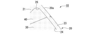
- the sealing resin 40 is arranged in the through hole 24.
- the sealing resin 40 seals between the outer surface of the magnet 30 and the inner surface of the through hole 24.
- the same adhesive as the adhesive forming the adhesive layer 22 can be adopted.
- As the sealing resin 40 a composition containing (1) an acrylic resin, (2) an epoxy resin, (3) an acrylic resin and an epoxy resin can be applied.
- the adhesive of the adhesive layer 22 and the adhesive of the sealing resin 40 may be the same or different.
- the sealing resin 40 seals the second gap 26.
- the yield stress of the sealing resin 40 is preferably 10 MPa or more and 200 MPa or less. When the yield stress of the sealing resin 40 is within this range, the stress generated in the adhesive layer 22 can be reduced.
- the various dimensions of the rotor 10 are preferably the dimensions shown below, for example.
- Stack thickness of laminated core 20 30 mm or more and 300 mm or less
- the maximum amount of displacement of the outer edge 20a of the laminated core 20 in the radial direction is 0.1 mm or less.
- the maximum displacement amount is 0.1 mm or less.
- the maximum amount of displacement of the outer edge 20a of the laminated core 20 in the radial direction can be obtained by, for example, the following methods (1) and (2).
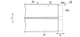
- Dimension D) shown in FIG. 12 is obtained, and the maximum value among the values obtained by adding the elastic deformation during rotation to the change amount (hereinafter, also referred to as the external displacement amount) is defined as the maximum displacement amount.
- the displacement amount can be measured using, for example, a laser displacement meter.
- the yield stress of the steel sheet 21 (yield, strength) as a YP R (MPa)
- yield stress (yield point, strength) of the adhesive layer 22 was a YP B (MPa)
- the values of YP R and YP B satisfies the following formula (1) and the following equation (2).
- A 0.105
- B 17,000
- C 17,000
- D 410
- E 30.
- Each value of YP R and YP B is to satisfy the equation (1), when the rotor 10 is rotated at the maximum speed, it is restricted that the bridge 23 of the steel plate 21 is plastically deformed deforms elastically region To. In other words, the bridge 23 is elastically deformed and not plastically deformed. Further, when the rotor 10 rotates at 11000 rpm, the maximum amount of displacement of the outer edge 20a of the laminated core 20 in the radial direction is 0.1 mm or less. When the rotor 10 rotates at 11000 rpm, the bridge 23 is deformed within the elastic region, so that at least the outer edge 20a of the laminated core 20 is deformed by about 0.020 ⁇ m in the radial direction. The maximum amount of radial displacement of the outer edge 20a of the laminated core 20 may be 30 ⁇ m or more.
- each value of YP R and YP B is to satisfy the equation (2) can be accommodated in an optimal range yield stress YP B of the adhesive layer 22.
- the yield stress YP B of the adhesive layer 22 is of less than 0.1 times the yield stress YP R of the steel plate 21, there is a risk of deformation is too low yield stress YP B of the adhesive layer 22 at a low rotation speed. If the yield stress YP B of the adhesive layer 22 is 10 times greater than the yield stress YP R of the steel plate 21, the yield stress YP B is too high the effect of the adhesive layer 22 is saturated, and does not hold economy.
- the yield stress YP R of the steel sheet 21 is preferably less than 150 MPa 580 MPa.
- the yield stress YP B of the adhesive layer 22 is preferably 10 MPa or more and 200 MPa or less.
- the hardness of the steel sheet 21 is measured, and the hardness is converted into tensile strength using a hardness conversion table (JIS handbook) based on the obtained hardness. Since the general yield ratio of the steel material is 0.73 (0.69 to 0.75), the yield stress of the steel sheet 21 can be calculated from the converted tensile strength.
- JIS handbook a hardness conversion table
- An example of a method for measuring the yield stress YP B of the adhesive layer 22 is the method shown below. That is, the adhesive layer 22 used for the laminated core 20 is cut into a test piece having a predetermined shape (for example, a rectangular shape of 10 mm ⁇ 110 mm). Then, using this test piece, a tensile test conforming to JIS K 7161-1 (2014) is carried out.
- a predetermined shape for example, a rectangular shape of 10 mm ⁇ 110 mm.
- test piece is a test piece independently using that material instead of creating a test piece from the rotor 10.
- a method of solidifying the adhesive into strips to prepare a sample piece of the adhesive layer 22 and performing a tensile test on the sample piece is recommended.
- a thin filter paper may be attached to the back surface to prepare a sample piece.
- the shape of the test piece may be a shape conforming to JIS K 7161-2: 2014.
- an adhesive layer 22 is obtained by preparing an approximately 30% by mass hydrochloric acid aqueous solution, immersing the laminated core 20 in the hydrochloric acid aqueous solution, and dissolving the steel plate 21. You may. The immersion time can be appropriately adjusted according to the amount and size of the steel sheet 21. Further, especially when the laminated core 20 is large, the hydrochloric acid aqueous solution may be replaced in the middle in order to promote the dissolution reaction. After all the steel plates 21 are melted, the adhesive layer 22 is taken out and washed. After cleaning, the test piece is processed into a test piece conforming to JIS K 7161-2: 2014, and the yield stress of the adhesive layer 22 is evaluated. The composition of the adhesive layer 22 may be analyzed by infrared spectroscopy (FT-IR) or the like, and a test piece may be prepared from the same material using the analysis result.
- FT-IR infrared spectroscopy
- a motor was prepared to confirm the relationship between the rotation speed of the rotor 10 and the amount of external displacement.
- a rotor 10 having a diameter of 162 mm was incorporated in this motor.
- the rotor 10 has a yield stress YP R is 400 MPa, the steel sheet 21 having a thickness of 0.25 mm, the yield stress YP B is 12 MPa, the adhesive layer 22 having a thickness of 2.5 [mu] m, the laminated core 20 in which the laminate.
- a rotor 10 of the same size is assumed.
- the rotation speed of the rotor 10 was changed from 0 rpm to 17,000 rpm, and the amount of external displacement of the rotor 10 was measured.
- This external displacement amount is the external displacement amount with respect to the specific measurement point P as shown in FIG. 1 in the outer edge 20a of the laminated core 20.
- the measurement point P is a position (a part of the bridge 23) of the outer edge 20a of the rotor 10 that intersects the virtual line L.
- the results are shown in Fig. 4.
- the horizontal axis of FIG. 4 indicates the rotation speed of the rotor 10.
- the vertical axis of FIG. 4 indicates the amount of external displacement at the measurement point.
- the specific rotation speed 14000 rpm
- FIGS. 5 to 10 show a case where the rotation speed of the rotor 10 is 14000 rpm. 7 and 8 show a case where the rotation speed of the rotor 10 is 15000 rpm. 9 and 10 show a case where the rotation speed of the rotor 10 is 16000 rpm.
- mises stress refers to the equivalent stress used to indicate the stress state generated inside an object with a single value.
- FIGS. 5 and 6 two types of hatches, a thin hatch and a dark hatch, are shown on the steel plate 21.
- a thin hatch means that the Mises stress is less than 380 MPa.
- a dark hatch means that the Mises stress is 380 MPa to 430 MPa.
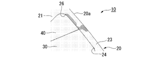
- the yield stress YP R of the steel plate 21 has a 356MPa, believed steel 21 is securely plastically deformed dark hatched regions.
- the amount of external displacement of the rotor 10 can be reduced by suppressing the radial stretching of the laminated steel plates 21 when the rotation speed of the rotor 10 is increased.
- the inventor of the present application can consider a measure of suppressing the stretching of the steel sheet 21 by the adhesive layer 22.
- the strength of the adhesive used for the adhesive layer 22 usually indicates the strength (adhesion force, peel strength) when the object to be adhered is peeled off, but in the present embodiment, the tension in the stacking direction Z is applied to the adhesive layer 22. Although stress is generated, the shearing force is extremely small, so the strength of the adhesive layer 22 itself (tensile strength), that is, the yield stress YP B that suppresses the internal deformation of the adhesive layer 22, is more important than the adhesive force. The higher the yield stress YP B that suppresses the internal deformation of the adhesive layer 22, the greater the effect of suppressing the stretching of the laminated steel sheet 21.
- the adhesive layer 22 suppresses the deformation of the steel plate 21. As a result, even if the rotation speed of the rotor 10 is increased, the amount of external displacement of the rotor 10 can be reduced.
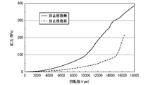
- FIG. 13 is a graph showing the relationship between the rotation speed of the rotor 10 and the stress generated in the adhesive layer 22 in the stacking direction Z.
- the horizontal axis of FIG. 13 indicates the rotation speed of the rotor 10.
- the vertical axis of FIG. 13 shows the stress generated in the adhesive layer 22.
- the solid line indicates the case where the sealing resin 40 is not present, and the broken line indicates the case where the sealing resin 40 (yield stress: 12 MPa) is present.
- Equation (3) is the right-hand side of equation (1) above.
- the strength of the adhesive layer 22 needs to satisfy the condition of the above formula (1).
- A 0.105
- B 17,000
- C 17,000
- D 410
- E 30.
- the rotational speed is 17000 rpm
- the diameter of the rotor 10 is 162 mm
- the plate thickness of the steel sheet 21 is 0.25 mm
- the thickness of the adhesive layer 22 is 0.002 mm
- the values of YP R and YP B is (1) It was confirmed by verification using an actual machine that the maximum displacement amount of the laminated core 20 was 0.1 mm or less of the target value by satisfying the above.
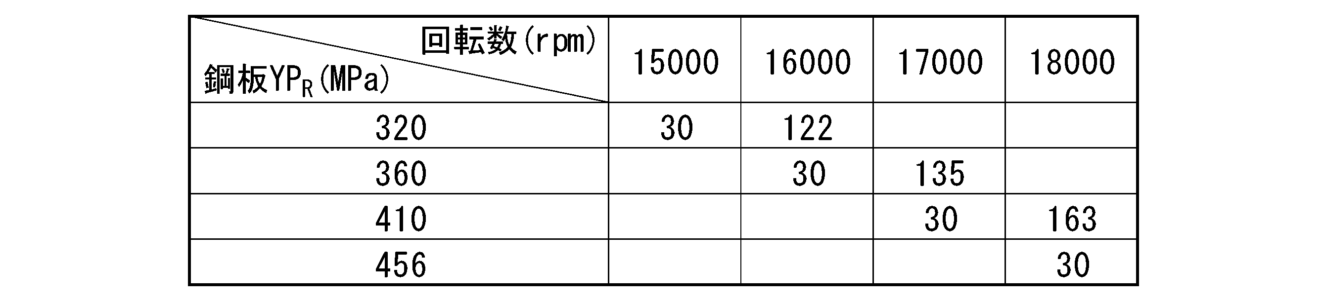
- the heading columns (first column) shows the YP R yield stress of the steel sheet 21 (MPa).
- the heading line (first line) indicates the rotation speed (rpm) of the rotor 10. The value in each cell, when the rotor 10 at a rotational speed of the header row of the column to which the cell belongs is rotated, and, when it is assumed yield stress YP R of the steel plate 21 heading column of the row to which the cell belongs , The value of the yield stress YP B (MPa) of the adhesive layer 22 required for the steel sheet 21 not to be plastically deformed is shown.
- the blank cell means that the yield stress YP B of the adhesive layer 22 under the conditions corresponding to the cell is not obtained.
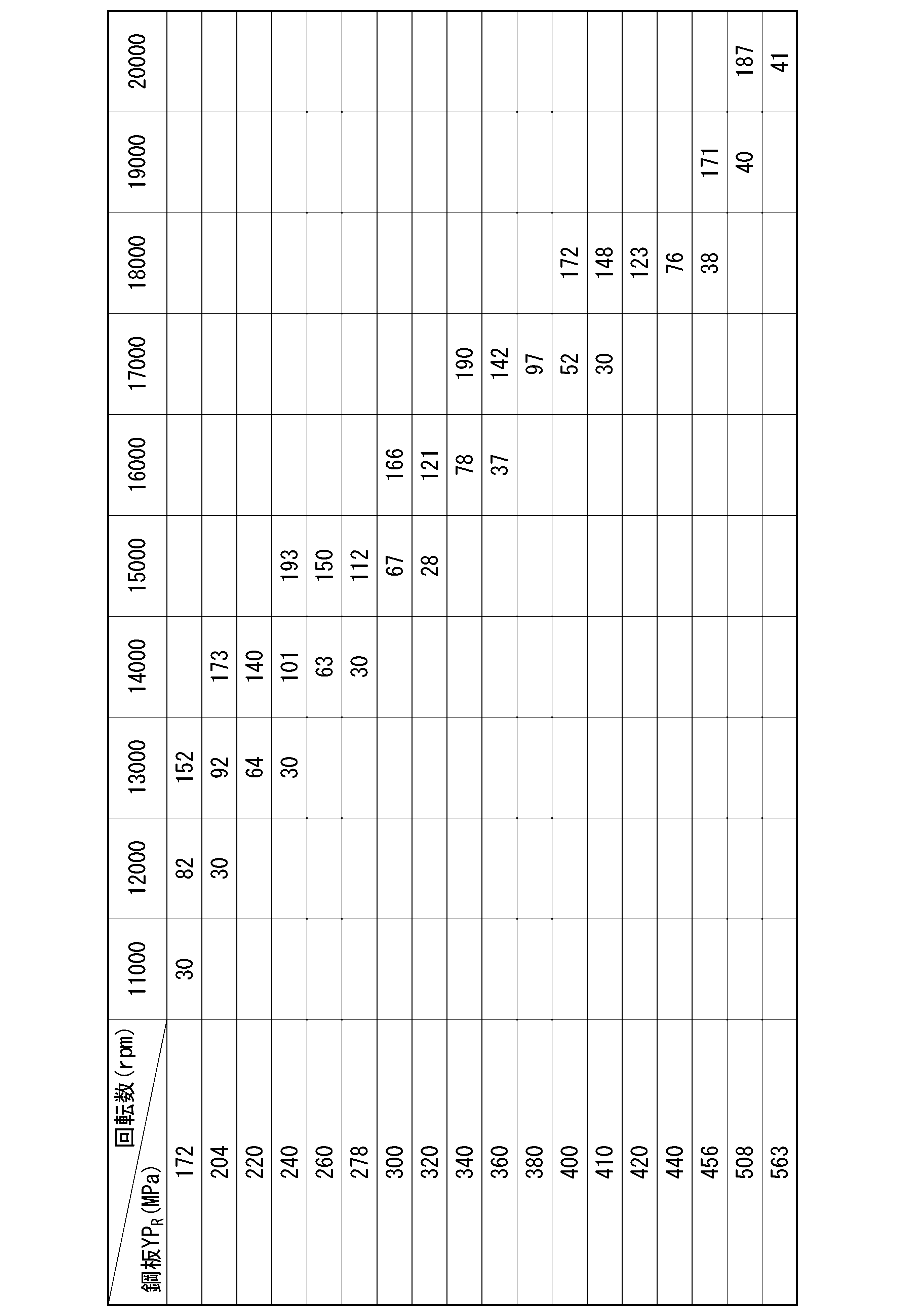
- Table 2 The view of Table 2 is the same as that of Table 1.
- Each value in the table in Table 2 is a value obtained by rounding the value obtained from the right side of the above equation (1) to the first decimal place.
- the yield stress YP B of the adhesive layer 22 is obtained in more cases than in Table 1.
- the rapid increase in the amount of external displacement can be realized by adjusting the yield stress of the adhesive layer 22 and adjusting the yield stress of the steel plate 21.
- the yield stress of the steel plate 21 and the yield stress of the adhesive layer 22 are set as follows. That is, when the rotor 10 rotates at the maximum rotation speed and the centrifugal force is transmitted from the magnet 30 to the laminated core 20, the deformation of the steel plate 21 is regulated (the stress generated in the steel plate 21 yields to the steel plate 21). as not reach the stress YP R), it sets the respective yield stress. Specifically, each yield stress is set so that each yield stress satisfies the above equations (1) and (2).
- the graph of FIG. 14 shows the boundary line obtained by the above equation (1).
- the horizontal axis of the graph in Figure 14 shows the YP R yield stress of the steel plate 21.
- the solid graph line shows the value on the right side of equation (1) (formula (3)) when the rotation speed is 16000 rpm.
- the broken line graph line shows the value on the right side of Eq. (1) (Equation (3)) when the rotation speed is 17,000 rpm.
- the graph line of the chain line shows the value on the right side of Eq. (1) (Equation (3)) when the rotation speed is 18,000 rpm.
- a combination of yield stress YP B of YP R and the adhesive layer 22 of the yield stress of the steel sheet 21, the upper right than the graph lines of the rotational speed shown in FIG. 14 Must be a combination included in the area.
- all the combinations can withstand each rotation speed.
- the rotor 10 is rotated This is not preferable because the maximum displacement of the outer edge of the laminated core in the radial direction of the rotor 10 exceeds 0.1 mm.
- the deformation strength can be increased in the upper right region, unnecessary high-strength steel sheets are used, which causes problems with punching accuracy and production inhibition due to die wear. It is important to design it so that it is on the line.
- a combination of a steel plate 21 strength of 360 MPa and an adhesive layer 22 strength of 142 MPa, or a steel plate 21 strength of 400 MPa and an adhesive layer 22 strength of 52 MPa is selected.
- the rotor 10 designed by using the above design method can be manufactured by a known manufacturing method.
- the method for manufacturing the rotor 10 using an adhesive includes a method of applying an adhesive to each of the steel plates 21, an impregnation immersion method, a method of using an adhesive processed into a tape shape, and an in-mold adhesive. Methods etc. have been proposed. In the present embodiment, any production method can be used for production, and the production method is not limited.
- the maximum displacement amount of the outer edge 20a of the laminated core 20 in the radial direction of the rotor 10 is 0.1 mm or less. Is. Therefore, even when the rotor 10 rotates at the maximum rotation speed (for example, a rotation speed exceeding 11000 rpm) when the automobile is running, the deformation of the outer shape of the rotor 10 is suppressed, and for example, the rotor 10 comes into contact with the stator. It is possible to prevent such things as doing. As a result, damage to the motor can be suppressed.
- the rotor 10 designed by the design method according to the present embodiment when the rotor 10 rotates at the maximum rotation speed during traveling of the automobile and the centrifugal force is transmitted from the magnet 30 to the laminated core 20.
- the adhesive layer 22 suppresses the deformation of the steel plate 21 in the radial direction, and the deformation of the steel plate 21 is restricted. Therefore, even when the rotor 10 rotates at the maximum rotation speed during traveling of the automobile, it is possible to suppress the deformation of the outer shape of the rotor 10 and prevent the rotor 10 from coming into contact with the stator, for example. As a result, damage to the motor can be suppressed.
- the rotor 10 rotates at the maximum rotation speed during traveling of the automobile, and when the centrifugal force is transmitted from the magnet 30 to the laminated core 20, the steel plate 21 is deformed in the radial direction of the rotor 10.
- the yield stress of the steel plate 21 and (2) the yield stress of the adhesive layer 22 are set so that the adhesive layer 22 is suppressed and the deformation of the steel plate 21 is regulated. That is, not only the yield stress of the steel plate 21 but also the yield stress of the adhesive layer 22 is taken into consideration. As a result, even when the yield stress of the steel sheet 21 is low to some extent, the deformation of the steel sheet 21 can be regulated by increasing the yield stress of the adhesive layer 22.
- the strength of the adhesive has a positive correlation with the cost, and the higher the strength of the adhesive, the higher the curing temperature is required.
- the optimum combination of the steel sheet 21 and the adhesive according to not only the cost but also the regionality and marketability. Can be selected. Therefore, it is possible to manufacture the rotor 10 that satisfies the requirements not only in terms of quality but also in terms of manufacturing.
- a pair of magnets 30 form one magnetic pole, but the present invention is not limited to this.
- One magnet 30 may form one magnetic pole, or three or more magnets 30 may form one magnetic pole. Equations (1) and (2) may not be satisfied.
- the sealing resin 40 may be omitted.
- the first gap 25 and the second gap 26 may be omitted.
Landscapes
- Engineering & Computer Science (AREA)
- Power Engineering (AREA)
- Manufacturing & Machinery (AREA)
- Iron Core Of Rotating Electric Machines (AREA)
- Permanent Field Magnets Of Synchronous Machinery (AREA)
- Manufacture Of Motors, Generators (AREA)
Abstract
Description
本発明に係るローターは、自動車の走行用のモーターに組み込まれる磁石埋め込み式ローターであって、互いに積層された鋼板、および積層方向に隣り合う前記鋼板を接着する接着層を有する積層コアと、前記積層コアに埋め込まれた磁石と、を備え、前記ローターが11000rpmで回転するときに、前記ローターの径方向へ向けた前記積層コアの外縁の最大変位量が0.1mm以下である。
なお、積層コアの外縁の径方向への最大変位量は、例えば、以下の(1)(2)の方法により求められる。
(1)積層コアの外縁において、ローターの周方向に沿った位置ごとに、回転前後における径方向の位置の変化量を求め、その変化量に回転中の弾性変形分を加えた値のうちの最大値を前記最大変位量とする。
(2)積層コアの外縁において、回転前後で最も変位する部分が事前にわかっている場合(例えば、理論上明らかであったり、シミュレーションや経験則により把握されていたりする場合)、その部分について、回転前後における径方向の位置の変化量を求め、その変化量に回転中の弾性変形分を加えた値を前記最大変位量とする。
前記鋼板の降伏応力YPRが、150MPa以上580MPa以下であってもよい。

0.1×YPR≦YPB≦10×YPR ・・・ (2)
そこでこの設計方法では、自動車の走行時における最大回転数でローターが回転するときに、鋼板の変形が規制されるように、(1)鋼板の降伏応力、(2)接着層の降伏応力を設定する。すなわち、鋼板の降伏応力だけでなく、接着層の降伏応力も考慮する。これにより、鋼板の降伏応力がある程度、低い場合であっても、接着層の降伏応力を高めることで、鋼板の変形を規制することができる。これは、接着層が、鋼板が担っていた変形を抑制する機能を一部担保することで鋼板の変形を抑制できるためである。
ミーゼス応力・特に厚み方向に発生する力が大きくなり、鋼板の板厚が減少することにより、鋼板は変形する。本発明者らが鋭意検討した結果、鋼板の板厚減少を抑制するためには、降伏応力が高い接着層を用いることが有効であることが分かった。接着層に降伏応力の高いものを用いることで、塑性域における鋼板の変形を抑制できる。これにより、鋼板の最小変形量は弾性域での変形量となり、使用限界となる鋼板の変形の上限を抑制できる。
通常、鋼板の強度は、高くなれば高くなるほど供給サプライヤーは限定され、コストも高くなる。一方、接着剤の強度はコストと概ね正相関があり、さらに接着剤には強度が高くなればなるほど高い硬化温度を求められる等、製造設備による制約もある。
この設計方法では、前述のように鋼板の降伏応力だけでなく接着層の降伏応力を考慮することで、コストのみならず地域性、市場性に応じた最適な鋼板および接着剤の組合せを選定することができる。したがって、品質面のみならず製造面での要求を満たすローターを製造することが可能である。つまり、本願発明を用いれば、先述した製造が難しく、供給サプライヤーが限定され、高コストとなる高強度鋼板を用いることなく、かつ、ロータの微細な部分に特殊な鋼板硬化処理や熱処理等の鋼板を強化する工程を増加させることなく、鋼板の変形を抑制できる。

0.1×YPR≦YPB≦10×YPR ・・・ (2)
図1から図3に示すように、ローター10は、自動車(例えば、ハイブリッド自動車や電気自動車)の走行用のモーターに組み込まれる。モーターは、インナーローター型のIPMモーター(埋込磁石30型モーター)である。ローター10は、磁石埋め込み式である。なお、モーターの最大回転数は、自動車に求められる性能特性に応じて決定され、最高速度、加速性あるいはモーターの小型化を重要視される場合には、高くなる傾向にある。前記最大回転数は、例えば、11000rpm以上で、より具体的には12000rpm以上20000rpm以下である。
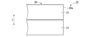
積層コア20は、互いに積層された鋼板21と、積層方向Zに隣り合う鋼板21を接着する接着層22と、を備えている。なお積層方向Zは、軸方向と一致している。また本実施形態では、積層方向Zに隣り合う鋼板21は、接着層22とは異なる手段(例えばかしめ)などによっては固定されていない。これらの鋼板21は、接着層22によってのみ固定されている。
(1)ローター10(積層コア20、鋼板21)の直径:50mm以上200mm以下
(2)鋼板21の厚さT1:0.1mm以上2.0mm以下
(3)接着層22の厚さT2:2μm以上4μm以下
(4)積層コア20の積厚:30mm以上300mm以下
(1)積層コア20の外縁20aにおいて、ローター10の周方向に沿った位置ごと(例えば、11.25°ごと、または15°ごと)に、回転前または後における径方向の位置の変化量(図12に示す寸法D)を求め、その変化量(以下、外形変位量ともいう)に回転中の弾性変形分を加えた値のうちの最大値を前記最大変位量とする。変位量の測定は例えば、レーザー変位計を用いて測定することができる。
(2)積層コア20の外縁20aにおいて、回転前後で最も変位する部分が事前にわかっている場合(例えば、理論上明らかであったり、シミュレーションや経験則により把握されていたりする場合)、その部分について、回転前後における径方向の位置の変化量を求め、その変化量を前記最大変位量とする。

すなわち、積層コア20に用いられる鋼板21から、所定の形状(例えば、35mm×250mmの矩形状)の試験片に切り出す。その後、この試験片を用いて、JIS Z 2241:2011に準拠する引張試験を実施する。なお、積層コア20から鋼板21の試験片を切り出して降伏応力を測定する場合は、例えば、硬度測定の結果を基に引張強度に変換する方法がある。具体的には、鋼板21の硬度を測定し、得られた硬度を基に硬さ換算表(JISハンドブック)を用いて、硬度を引張強度に換算する。鋼材の一般的な降伏比が0.73(0.69~0.75)であることから、換算後の引張強度から鋼板21の降伏応力を算出することができる。
すなわち、積層コア20に用いられる接着層22から、所定の形状(例えば、10mm×110mmの矩形状)の試験片に切り出す。その後、この試験片を用いて、JIS K 7161-1(2014)に準拠する引張試験を実施する。
ローター10の回転数と外形変位量の関係について確認するために、モーターを準備した。このモーターには、直径162mmのローター10を組み込んだ。このローター10は、降伏応力YPRが400MPa、板厚0.25mmの鋼板21と、降伏応力YPBが12MPa、厚み2.5μmの接着層22と、を積層した積層コア20を有する。なお以下に示す各試験においても、同サイズのローター10を前提とする。
ここで、外形変位量の急増の要因について検討するため、本願発明者は、高速回転時のブリッジ23に生じる応力をFEM解析により定量化した。
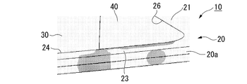
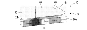
鋼板21のブリッジ23におけるミーゼス応力分布の解析結果を、図5から図10に示す。図5および図6は、ローター10の回転数が14000rpmの場合を示している。図7および図8は、ローター10の回転数が15000rpmの場合を示している。図9および図10は、ローター10の回転数が16000rpmの場合を示している。
例えば、図5および図6では、鋼板21上に薄いハッチと濃いハッチとの2種類のハッチが示されている。これらの図において、薄いハッチは、ミーゼス応力が380MPa未満であることを意味している。濃いハッチは、ミーゼス応力が380MPa~430MPaであることを意味している。なおこのローター10において、鋼板21の降伏応力YPRは356MPaとしており、濃いハッチの領域では鋼板21が確実に塑性変形していると考えられる。
前述のような応力の増加の要因について検討するために、ローター10の回転前後における鋼板21の形状について考察する。
図11に示すように、ローター10が回転していないときには、遠心力が作用しておらず、鋼板21は延伸していない。
一方、図12に示すように、ローター10が高速回転するときには、ローター10の径方向の遠心力が増加するため、鋼板21がローター10の径方向に延伸する(図12中の破線)。このように鋼板21が延伸すると、鋼板21の外周部分の板厚が減少する。その結果、応力集中が引き起こされ、前述のようなミーゼス応力の急増が発生していると考えられる。
そして本願発明者は、その方策として、接着層22によって鋼板21の延伸を抑制する方策が考えられる。
接着層22の内部変形を抑制する降伏応力YPBが高いほど、積層された鋼板21の延伸を抑制する効果が大きくなる。すなわち、ローター10の径方向に引張応力が生じたときに、接着層22が鋼板21の変形を抑制する。これにより、ローター10の回転数が高くなっても、ローター10の外形変位量を低減することが可能となる。
接着層22の降伏応力の基準値は、ローター10の回転数をω、鋼板21の降伏応力をYPRとしたときに、下記(3)式に基づいて計算することができることを発明者は見出した。(3)式は、上記(1)式における右辺である。接着層22の強度は上記(1)式の条件を満足することが必要である。

まず、ローター10の回転数と、塑性変形が生じない鋼板21の降伏応力YPRおよび接着層22の降伏応力YPBと、の関係を、FEM解析を用いて求めた。結果を下記表1に示す。
上記ローター10の設計に際しては、鋼板21の降伏応力および接着層22の降伏応力を以下のように設定する。すなわち、前記最大回転数でローター10が回転し、磁石30から積層コア20に遠心力が伝達されるときに、鋼板21の変形が規制されるように(鋼板21に生じる応力が鋼板21の降伏応力YPRに至らないように)、各降伏応力を設定する。具体的には、各降伏応力が上記(1)式および上記(2)式を満たすように、各降伏応力を設定する。
上記設計方法を用いて設計されたローター10は、公知の製造方法で製造することができる。例えば、接着剤を用いたローター10の製造方法は、鋼板21一枚一枚に接着剤を塗布する方法、含侵浸漬法、テープ状に加工した接着剤を使用する方法さらには金型内接着方法等が提案されている。本実施形態では、いずれの製造方法においても製造可能であり、製造方法について限定されない。
この設計方法では、前述のように鋼板21の降伏応力だけでなく接着層22の降伏応力を考慮することで、コストのみならず地域性、市場性に応じた最適な鋼板21および接着剤の組合せを選定することができる。したがって、品質面のみならず製造面での要求を満たすローター10を製造することが可能である。
(1)式および(2)式が満たされていなくてもよい。
封止樹脂40がなくてもよい。第1隙間25および第2隙間26がなくてもよい。
20 積層コア
20a 外縁
21 鋼板
22 接着層
23 ブリッジ
24 貫通孔
30 磁石
40 封止樹脂
Claims (9)
- 自動車の走行用のモーターに組み込まれる磁石埋め込み式ローターであって、
互いに積層された鋼板、および積層方向に隣り合う前記鋼板を接着する接着層を有する積層コアと、
前記積層コアに埋め込まれた磁石と、を備え、
前記ローターが11000rpmで回転するときに、前記ローターの径方向へ向けた前記積層コアの外縁の最大変位量が0.1mm以下であるローター。 - 前記鋼板の降伏応力YPRが、150MPa以上580MPa以下である、請求項1に記載のローター。
- 前記鋼板の降伏応力をYPR(MPa)とし、前記接着層の降伏応力をYPB(MPa)とし、前記自動車の走行時における最大回転数をω(rpm)としたとき、
下記(1)式を満たす請求項1または2に記載のローター。

- 下記(2)式を更に満たす請求項3に記載のローター。
0.1×YPR≦YPB≦10×YPR ・・・ (2) - 前記磁石は、前記積層コアを前記積層方向に貫通する貫通孔内に配置され、
前記貫通孔内には、前記磁石の外面と前記貫通孔の内面との間を封止する封止樹脂が設けられている請求項1から4のいずれか1項に記載のローター。 - 自動車の走行用のモーターに組み込まれる磁石埋め込み式ローターの設計方法であって、
前記ローターは、
互いに積層された鋼板、および積層方向に隣り合う前記鋼板を接着する接着層を有する積層コアと、
前記積層コアに埋め込まれた磁石と、を備え、
前記設計方法では、前記自動車の走行時における最大回転数で前記ローターが回転するときに、前記ローターの径方向へ向けた前記積層コアの外縁の最大変位量が0.1mm以下となるように、前記鋼板の降伏応力および前記接着層の降伏応力を設定するローターの設計方法。 - 前記鋼板の降伏応力をYPR(MPa)とし、前記接着層の降伏応力をYPB(MPa)とし、前記最大回転数をω(rpm)としたとき、
下記(1)式を満たすように前記鋼板の降伏応力YPRおよび前記接着層の降伏応力YPBを設定する請求項6に記載のローターの設計方法。

- 下記(2)式を更に満たすように前記鋼板の降伏応力YPRおよび前記接着層の降伏応力YPBを設定する請求項7に記載のローターの設計方法。
0.1×YPR≦YPB≦10×YPR ・・・ (2) - 請求項6から8のいずれか1項に記載のローターの設計方法を用いるローターの製造方法。
Priority Applications (10)
| Application Number | Priority Date | Filing Date | Title |
|---|---|---|---|
| MYPI2022001222A MY209477A (en) | 2019-10-08 | 2020-10-06 | Rotor, method for designing rotor, and method for producing rotor |
| EP20874386.4A EP4044403B1 (en) | 2019-10-08 | 2020-10-06 | Rotor, rotor design method, and rotor manufacturing method |
| US17/642,906 US12126220B2 (en) | 2019-10-08 | 2020-10-06 | Rotor, method for designing rotor, and method for producing rotor |
| KR1020227008119A KR102667253B1 (ko) | 2019-10-08 | 2020-10-06 | 로터, 로터의 설계 방법 및 로터의 제조 방법 |
| PL20874386.4T PL4044403T3 (pl) | 2019-10-08 | 2020-10-06 | Rotor, sposób projektowania rotora i sposób wytwarzania rotora |
| MX2022003139A MX2022003139A (es) | 2019-10-08 | 2020-10-06 | Rotor, metodo para dise?ar rotor y metodo para producir rotor. |
| BR112022002830-0A BR112022002830B1 (pt) | 2019-10-08 | 2020-10-06 | Rotor com imã embutido, método para projetar um rotor com imã embutido, e, método para produzir um rotor |
| CN202080064967.XA CN114402506B (zh) | 2019-10-08 | 2020-10-06 | 转子、转子的设计方法及转子的制造方法 |
| CA3153666A CA3153666A1 (en) | 2019-10-08 | 2020-10-06 | Rotor, method for designing rotor, and method for producing rotor |
| JP2021551654A JP7381940B2 (ja) | 2019-10-08 | 2020-10-06 | ローター、ローターの設計方法およびローターの製造方法 |
Applications Claiming Priority (2)
| Application Number | Priority Date | Filing Date | Title |
|---|---|---|---|
| JP2019185110 | 2019-10-08 | ||
| JP2019-185110 | 2019-10-08 |
Publications (1)
| Publication Number | Publication Date |
|---|---|
| WO2021070795A1 true WO2021070795A1 (ja) | 2021-04-15 |
Family
ID=75436831
Family Applications (1)
| Application Number | Title | Priority Date | Filing Date |
|---|---|---|---|
| PCT/JP2020/037796 Ceased WO2021070795A1 (ja) | 2019-10-08 | 2020-10-06 | ローター、ローターの設計方法およびローターの製造方法 |
Country Status (11)
| Country | Link |
|---|---|
| US (1) | US12126220B2 (ja) |
| EP (1) | EP4044403B1 (ja) |
| JP (1) | JP7381940B2 (ja) |
| KR (1) | KR102667253B1 (ja) |
| CN (1) | CN114402506B (ja) |
| CA (1) | CA3153666A1 (ja) |
| MX (1) | MX2022003139A (ja) |
| MY (1) | MY209477A (ja) |
| PL (1) | PL4044403T3 (ja) |
| TW (1) | TWI788709B (ja) |
| WO (1) | WO2021070795A1 (ja) |
Cited By (2)
| Publication number | Priority date | Publication date | Assignee | Title |
|---|---|---|---|---|
| WO2023171645A1 (ja) | 2022-03-08 | 2023-09-14 | 日本製鉄株式会社 | 積層コア、ロータ及び積層コアの製造方法 |
| EP4376275A4 (en) * | 2021-07-21 | 2025-07-16 | Daewon Kang Up Co Ltd | METHOD FOR MANUFACTURING LAMINATED CORE |
Families Citing this family (1)
| Publication number | Priority date | Publication date | Assignee | Title |
|---|---|---|---|---|
| JP7763821B2 (ja) * | 2023-10-24 | 2025-11-04 | ヤマハ発動機株式会社 | ロータ及びロータの製造方法 |
Citations (7)
| Publication number | Priority date | Publication date | Assignee | Title |
|---|---|---|---|---|
| JP2002369422A (ja) * | 2001-06-11 | 2002-12-20 | Hitachi Ltd | 永久磁石式回転電機 |
| JP2005094940A (ja) * | 2003-09-18 | 2005-04-07 | Nippon Steel Corp | 電磁鋼板ロータの製造方法 |
| WO2012102030A1 (ja) * | 2011-01-28 | 2012-08-02 | パナソニック株式会社 | ブラシレスモータおよびそれを搭載した電気機器 |
| JP2014197981A (ja) | 2014-07-02 | 2014-10-16 | 黒田精工株式会社 | 積層鉄心の製造装置 |
| JP2014220911A (ja) * | 2013-05-08 | 2014-11-20 | 株式会社三井ハイテック | 回転子積層鉄心および回転子積層鉄心の製造方法 |
| JP2019161928A (ja) * | 2018-03-15 | 2019-09-19 | 日本製鉄株式会社 | モータコア |
| JP2019185110A (ja) | 2018-04-02 | 2019-10-24 | パイオニア株式会社 | 情報提供装置、情報提供方法及びプログラム |
Family Cites Families (18)
| Publication number | Priority date | Publication date | Assignee | Title |
|---|---|---|---|---|
| US2554226A (en) * | 1949-12-30 | 1951-05-22 | Gen Electric | Dynamoelectric machine core mounting |
| JP2004088970A (ja) | 2002-08-29 | 2004-03-18 | Hitachi Ltd | 積層鉄心とそれを用いた回転電機およびトランス |
| JP4311127B2 (ja) * | 2003-08-20 | 2009-08-12 | 住友金属工業株式会社 | 高張力無方向性電磁鋼板およびその製造方法 |
| WO2005031946A1 (ja) * | 2003-09-22 | 2005-04-07 | Nissan Motor Co., Ltd. | 低鉄損の電磁鋼板を使用するロータ、ロータ製造方法およびレーザピーニング方法並びにレーザピーニング装置 |
| EP2144348B1 (en) * | 2007-04-27 | 2017-04-05 | Mitsui High-Tec, Inc. | Laminated iron core and production of the same |
| JP5337548B2 (ja) * | 2009-03-27 | 2013-11-06 | 株式会社日立産機システム | 永久磁石モータ |
| CN102326316B (zh) * | 2010-03-15 | 2014-05-07 | 丰田自动车株式会社 | 转子及其制造方法 |
| JP5531738B2 (ja) * | 2010-04-08 | 2014-06-25 | トヨタ自動車株式会社 | 電動機およびロータの製造方法 |
| JP5215486B1 (ja) * | 2011-11-14 | 2013-06-19 | ファナック株式会社 | 永久磁石同期電動機の回転子、電動機および工作機械 |
| IN2014DN07130A (ja) * | 2012-03-01 | 2015-04-24 | Sumitomo Bakelite Co | |
| JP2014096902A (ja) * | 2012-11-08 | 2014-05-22 | Toyota Motor Corp | 中空ロータ |
| TW201444903A (zh) | 2013-05-22 | 2014-12-01 | Sumitomo Bakelite Co | 固定用樹脂組成物、轉子、汽車、及轉子之製造方法 |
| JP2015002649A (ja) * | 2013-06-18 | 2015-01-05 | 日新製鋼株式会社 | Ipmモータの回転子及びそれを用いたipmモータ |
| JP2015006088A (ja) * | 2013-06-21 | 2015-01-08 | トヨタ紡織株式会社 | 回転電機のコア及びその製造方法 |
| WO2017047253A1 (ja) * | 2015-09-16 | 2017-03-23 | 三菱電機株式会社 | 回転電機の回転子、及び回転電機 |
| DE112018003942T5 (de) * | 2017-08-01 | 2020-05-07 | Denso Corporation | Magnetische Erzeugungseinrichtung für einen Motor, Weichmagnetischer Kern und Verfahren zur Herstellung eines Magneten |
| JP6909135B2 (ja) * | 2017-11-22 | 2021-07-28 | 株式会社三井ハイテック | 鉄心製品の製造方法 |
| US12325811B2 (en) | 2017-12-18 | 2025-06-10 | Threebond Co., Ltd. | Radical-polymerizable adhesive composition for laminating and bonding steel plates, adhesive laminate, motor, and method for manufacturing adhesive laminate |
-
2020
- 2020-10-06 EP EP20874386.4A patent/EP4044403B1/en active Active
- 2020-10-06 US US17/642,906 patent/US12126220B2/en active Active
- 2020-10-06 WO PCT/JP2020/037796 patent/WO2021070795A1/ja not_active Ceased
- 2020-10-06 CA CA3153666A patent/CA3153666A1/en active Pending
- 2020-10-06 JP JP2021551654A patent/JP7381940B2/ja active Active
- 2020-10-06 PL PL20874386.4T patent/PL4044403T3/pl unknown
- 2020-10-06 MY MYPI2022001222A patent/MY209477A/en unknown
- 2020-10-06 MX MX2022003139A patent/MX2022003139A/es unknown
- 2020-10-06 CN CN202080064967.XA patent/CN114402506B/zh active Active
- 2020-10-06 TW TW109134617A patent/TWI788709B/zh active
- 2020-10-06 KR KR1020227008119A patent/KR102667253B1/ko active Active
Patent Citations (7)
| Publication number | Priority date | Publication date | Assignee | Title |
|---|---|---|---|---|
| JP2002369422A (ja) * | 2001-06-11 | 2002-12-20 | Hitachi Ltd | 永久磁石式回転電機 |
| JP2005094940A (ja) * | 2003-09-18 | 2005-04-07 | Nippon Steel Corp | 電磁鋼板ロータの製造方法 |
| WO2012102030A1 (ja) * | 2011-01-28 | 2012-08-02 | パナソニック株式会社 | ブラシレスモータおよびそれを搭載した電気機器 |
| JP2014220911A (ja) * | 2013-05-08 | 2014-11-20 | 株式会社三井ハイテック | 回転子積層鉄心および回転子積層鉄心の製造方法 |
| JP2014197981A (ja) | 2014-07-02 | 2014-10-16 | 黒田精工株式会社 | 積層鉄心の製造装置 |
| JP2019161928A (ja) * | 2018-03-15 | 2019-09-19 | 日本製鉄株式会社 | モータコア |
| JP2019185110A (ja) | 2018-04-02 | 2019-10-24 | パイオニア株式会社 | 情報提供装置、情報提供方法及びプログラム |
Non-Patent Citations (2)
| Title |
|---|
| "ELECTRICAL STEEL SHEETS. Representative examples of mechanical properties and space factor", NIPPON STEEL & SUMITOMO METAL, 2018, pages 21, XP055817482, Retrieved from the Internet <URL:https://pdf4pro.com/amp/download?data_id=52c68c&slug=d003jec-electrical-steel-sheets-nssmc-com> [retrieved on 20201120] * |
| See also references of EP4044403A4 |
Cited By (3)
| Publication number | Priority date | Publication date | Assignee | Title |
|---|---|---|---|---|
| EP4376275A4 (en) * | 2021-07-21 | 2025-07-16 | Daewon Kang Up Co Ltd | METHOD FOR MANUFACTURING LAMINATED CORE |
| WO2023171645A1 (ja) | 2022-03-08 | 2023-09-14 | 日本製鉄株式会社 | 積層コア、ロータ及び積層コアの製造方法 |
| KR20240135069A (ko) | 2022-03-08 | 2024-09-10 | 닛폰세이테츠 가부시키가이샤 | 적층 코어, 로터 및 적층 코어의 제조 방법 |
Also Published As
| Publication number | Publication date |
|---|---|
| US12126220B2 (en) | 2024-10-22 |
| JPWO2021070795A1 (ja) | 2021-04-15 |
| PL4044403T3 (pl) | 2026-04-20 |
| TW202115993A (zh) | 2021-04-16 |
| TWI788709B (zh) | 2023-01-01 |
| BR112022002830A2 (pt) | 2022-05-10 |
| MY209477A (en) | 2025-07-11 |
| JP7381940B2 (ja) | 2023-11-16 |
| EP4044403A4 (en) | 2023-10-25 |
| MX2022003139A (es) | 2022-04-06 |
| EP4044403B1 (en) | 2026-01-07 |
| US20220368182A1 (en) | 2022-11-17 |
| KR102667253B1 (ko) | 2024-05-21 |
| EP4044403A1 (en) | 2022-08-17 |
| CN114402506A (zh) | 2022-04-26 |
| KR20220045210A (ko) | 2022-04-12 |
| CA3153666A1 (en) | 2021-04-15 |
| CN114402506B (zh) | 2024-11-26 |
Similar Documents
| Publication | Publication Date | Title |
|---|---|---|
| EP3902108B1 (en) | Laminated core and rotating electric machine | |
| TWI744743B (zh) | 積層鐵芯及旋轉電機 | |
| EP3902105B1 (en) | Laminated core and rotating electric machine | |
| TWI724690B (zh) | 積層鐵芯及旋轉電機 | |
| TWI732384B (zh) | 積層鐵芯及旋轉電機 | |
| JP7381940B2 (ja) | ローター、ローターの設計方法およびローターの製造方法 | |
| JP2023017058A (ja) | ステータ用接着積層コア | |
| JP7207610B2 (ja) | 電磁鋼板用コーティング組成物、接着用表面被覆電磁鋼板及び積層鉄心 | |
| CN104137395B (zh) | 旋转的电机器 | |
| EP3340435A1 (en) | Stator core and motor equipped with same | |
| EP3993224B1 (en) | Core block, stacked core, and rotating electrical machine | |
| TW202203262A (zh) | 電磁鋼板、積層鐵芯及旋轉電機 | |
| RU2798143C1 (ru) | Ротор, способ компоновки ротора и способ производства ротора | |
| US20250149930A1 (en) | Motor core manufacturing method, power generator manufacturing method, motor core, and power generator | |
| BR112022002830B1 (pt) | Rotor com imã embutido, método para projetar um rotor com imã embutido, e, método para produzir um rotor | |
| BR112021008895B1 (pt) | Núcleo laminado e motor elétrico |
Legal Events
| Date | Code | Title | Description |
|---|---|---|---|
| 121 | Ep: the epo has been informed by wipo that ep was designated in this application |
Ref document number: 20874386 Country of ref document: EP Kind code of ref document: A1 |
|
| ENP | Entry into the national phase |
Ref document number: 2021551654 Country of ref document: JP Kind code of ref document: A |
|
| REG | Reference to national code |
Ref country code: BR Ref legal event code: B01A Ref document number: 112022002830 Country of ref document: BR |
|
| ENP | Entry into the national phase |
Ref document number: 3153666 Country of ref document: CA |
|
| ENP | Entry into the national phase |
Ref document number: 20227008119 Country of ref document: KR Kind code of ref document: A |
|
| NENP | Non-entry into the national phase |
Ref country code: DE |
|
| ENP | Entry into the national phase |
Ref document number: 112022002830 Country of ref document: BR Kind code of ref document: A2 Effective date: 20220215 |
|
| ENP | Entry into the national phase |
Ref document number: 2020874386 Country of ref document: EP Effective date: 20220509 |
|
| WWG | Wipo information: grant in national office |
Ref document number: MX/A/2022/003139 Country of ref document: MX |
|
| WWG | Wipo information: grant in national office |
Ref document number: 11202202639Y Country of ref document: SG |
|
| WWP | Wipo information: published in national office |
Ref document number: 11202202639Y Country of ref document: SG |
|
| WWG | Wipo information: grant in national office |
Ref document number: 2020874386 Country of ref document: EP |