WO2021074958A1 - ドリル - Google Patents
ドリル Download PDFInfo
- Publication number
- WO2021074958A1 WO2021074958A1 PCT/JP2019/040474 JP2019040474W WO2021074958A1 WO 2021074958 A1 WO2021074958 A1 WO 2021074958A1 JP 2019040474 W JP2019040474 W JP 2019040474W WO 2021074958 A1 WO2021074958 A1 WO 2021074958A1
- Authority
- WO
- WIPO (PCT)
- Prior art keywords
- cutting edge
- main
- thinning
- drill
- central axis
- Prior art date
- Legal status (The legal status is an assumption and is not a legal conclusion. Google has not performed a legal analysis and makes no representation as to the accuracy of the status listed.)
- Ceased
Links
Images



Classifications
-
- B—PERFORMING OPERATIONS; TRANSPORTING
- B23—MACHINE TOOLS; METAL-WORKING NOT OTHERWISE PROVIDED FOR
- B23B—TURNING; BORING
- B23B51/00—Tools for drilling machines
- B23B51/02—Twist drills
-
- B—PERFORMING OPERATIONS; TRANSPORTING
- B23—MACHINE TOOLS; METAL-WORKING NOT OTHERWISE PROVIDED FOR
- B23B—TURNING; BORING
- B23B2222/00—Materials of tools or workpieces composed of metals, alloys or metal matrices
- B23B2222/84—Steel
-
- B—PERFORMING OPERATIONS; TRANSPORTING
- B23—MACHINE TOOLS; METAL-WORKING NOT OTHERWISE PROVIDED FOR
- B23B—TURNING; BORING
- B23B2251/00—Details of tools for drilling machines
- B23B2251/04—Angles, e.g. cutting angles
-
- B—PERFORMING OPERATIONS; TRANSPORTING
- B23—MACHINE TOOLS; METAL-WORKING NOT OTHERWISE PROVIDED FOR
- B23B—TURNING; BORING
- B23B2251/00—Details of tools for drilling machines
- B23B2251/12—Cross sectional views of the cutting edges
- B23B2251/125—Rounded cutting edges
-
- B—PERFORMING OPERATIONS; TRANSPORTING
- B23—MACHINE TOOLS; METAL-WORKING NOT OTHERWISE PROVIDED FOR
- B23B—TURNING; BORING
- B23B2251/00—Details of tools for drilling machines
- B23B2251/14—Configuration of the cutting part, i.e. the main cutting edges
-
- B—PERFORMING OPERATIONS; TRANSPORTING
- B23—MACHINE TOOLS; METAL-WORKING NOT OTHERWISE PROVIDED FOR
- B23B—TURNING; BORING
- B23B2251/00—Details of tools for drilling machines
- B23B2251/18—Configuration of the drill point
- B23B2251/182—Web thinning
-
- B—PERFORMING OPERATIONS; TRANSPORTING
- B23—MACHINE TOOLS; METAL-WORKING NOT OTHERWISE PROVIDED FOR
- B23B—TURNING; BORING
- B23B2251/00—Details of tools for drilling machines
- B23B2251/44—Margins, i.e. the narrow portion of the land which is not cut away to provide clearance on the circumferential surface
- B23B2251/443—Double margin drills
Definitions
- This disclosure relates to drills.
- Patent Document 1 Japanese Unexamined Patent Publication No. 7-80714 describes a drill. A cutting edge is formed at the tip of the drill described in Patent Document 1, and the drill described in Patent Document 1 is rotated around a central axis to perform drilling by the cutting edge.
- the cutting edge of the drill described in Patent Document 1 is a portion formed on the ridge line between the tip surface and the chip discharge groove (hereinafter referred to as "main cutting edge”), and the ridge line between the tip surface and the thinning surface. It has a portion formed in (hereinafter referred to as "thinning cutting edge”).
- thinning cutting edge the portion formed in
- honing is performed on the main cutting edge (the surface formed by honing is hereinafter referred to as "main rake surface”).
- the width of the main rake face is 0.01 mm or more and 0.05 mm or less.
- the angle formed by the main rake face and the central axis is ⁇ 30 ° or more and ⁇ 20 ° or less.
- the drill of the present disclosure includes a tip and a rear end that are rotated around a central axis and are ends in a direction along the central axis, an outer peripheral surface, and a cutting edge that extends from the outer peripheral surface to the central axis at the tip. , A flank that is connected to the cutting edge, a flute that is formed on the outer peripheral surface and extends spirally around the central axis from the tip to the rear end, and a thinning rake face that is connected to the flute. ..
- the cutting edge has a main cutting edge extending from the outer peripheral surface and a thinning cutting edge connected to the end of the main cutting edge on the side opposite to the outer peripheral surface.
- the flute includes the main rake face that extends from the flank to the main cutting edge.
- the thinning rake face is connected to the thinning cutting edge from the side opposite to the flank surface.
- the thinning rake face is flush with the main rake face.
- the angle between the main rake face and the central axis is -18 ° or more and 7 ° or less.
- the width of the main rake face is 0.07 mm or more and 1.5 mm or less.
- FIG. 1 is a side view of the drill 10.
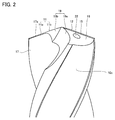
- FIG. 2 is an enlarged side view of the drill 10 in the vicinity of the tip 10a.
- FIG. 3 is a front view of the drill 10.
- FIG. 4 is a cross-sectional view of the drill 10 orthogonal to the central axis A.
- FIG. 5 is a view in which the cross-sectional view taken along the line V of FIG. 3 is rotated 180 ° clockwise.
- FIG. 6 is a view obtained by rotating the cross-sectional view of VI-VI of FIG. 3 clockwise by 180 °.
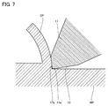
- FIG. 7 is a schematic view showing a cutting process by the drill 10.
- the width of the main rake face is as small as 0.01 mm or more and 0.05 mm or less. Therefore, the chips cut out from the work material by the main cutting edge may come into contact with the flute beyond the main rake face and cause crater wear on the flute. Crater wear on the flute may cause defects near the cutting edge.
- the angle formed by the main rake face and the central axis is -30 ° or more and -20 ° or less, and the chips cut out from the work material by the main cutting edge are large. Since it curls and the temperature near the main cutting edge tends to rise, there is room for improvement in the durability of the cutting edge.
- the present disclosure provides a drill capable of suppressing crater wear on a flute, improving the durability of a main cutting edge, and simplifying a manufacturing process.
- the drill according to the embodiment of the present disclosure is rotated around the central axis, and the tip and the rear end, which are the ends in the direction along the central axis, the outer peripheral surface, and the tip from the outer peripheral surface to the central axis.
- the cutting edge has a main cutting edge extending from the outer peripheral surface and a thinning cutting edge connected to the end of the main cutting edge on the side opposite to the outer peripheral surface.
- the flute includes the main rake face that extends from the flank to the main cutting edge.
- the thinning rake face is connected to the thinning cutting edge from the side opposite to the flank surface.
- the thinning rake face is flush with the main rake face.
- the angle between the main rake face and the central axis is -18 ° or more and 7 ° or less.
- the width of the main rake face is 0.07 mm or more and 1.5 mm or less.
- both the main rake surface and the thinning rake surface can be formed by a single polishing step. ..
- the angle formed by the main rake face and the central axis is -18 ° or more and 7 ° or less, the chips cut out from the work material by the main cutting edge are greatly curled. It's hard to do. As a result of the chips cut out from the work material being large and difficult to curl by the main cutting edge, the temperature of the main cutting edge during cutting is suppressed, and the durability of the main cutting edge can be improved.
- the width of the main rake face is relatively large, 0.07 mm or more and 1.5 mm or less, so the angle between the main rake face and the central axis is -18 ° or more and 7 ° or less. The strength of the cutting edge of the main cutting edge can be maintained even if it is relatively large.
- the angle between the main rake face and the flank may be 75 ° or more and 100 ° or less.
- the amount of centering of the cutting edge may be 0.05 times or more and 0.12 times or less the diameter of the drill.
- the temperature rise in the vicinity of the cutting edge can be further suppressed by reducing the cutting resistance between the cutting edge and the work material.
- the cutting edge may be round-honed.
- the radius of curvature of the cutting edge may be 0.015 mm or more and 0.3 mm or less.
- drill 10 Structure of the drill according to the embodiment
- the configuration of the drill (hereinafter referred to as “drill 10”) according to the embodiment will be described below.
- the drill 10 is, for example, a drill used for processing a work material made of low carbon steel.
- the low carbon steel is a steel having a carbon concentration of 0.25% by weight or less. Examples of low carbon steel include SCM415 defined in JIS standards.
- the drill 10 is made of, for example, cemented carbide.
- Cemented carbide is a sintered body of metal carbide grains containing a binder.
- the metal carbide particles are, for example, tungsten carbide (WC) particles, and the binder is, for example, cobalt (Co).
- FIG. 1 is a side view of the drill 10. As shown in FIG. 1, the drill 10 has a central axis A and is rotated around the central axis A. The drill 10 has a front end 10a and a rear end 10b. The front end 10a and the rear end 10b are the ends of the drill 10 in the direction along the central axis A. The rear end 10b is the opposite end of the tip 10a.
- FIG. 2 is an enlarged side view of the drill 10 in the vicinity of the tip 10a.
- FIG. 3 is a front view of the drill 10. In FIG. 3, the rotation direction of the drill 10 is indicated by an arrow. As shown in FIGS. 2 and 3, the drill 10 has an outer peripheral surface 10c.
- the outer peripheral surface 10c has a land 10d and a land 10e.
- the lands 10d and 10e are portions of the outer peripheral surface 10c on which the flutes 17 and flutes 18, which will be described later, are not formed.
- Land 10d has a leading edge 10da and a heel 10db.
- the leading edge 10da is the end of the land 10d on the flute 17 side.
- the heel 10db is the end of the land 10d on the opposite side of the leading edge 10da.
- the land 10d is composed of a first margin of 10 dc, a second margin of 10 dd, and a second taking surface of 10 de.
- the land 10e has a leading edge 10ea and a heel 10eb.
- the leading edge 10ea is the end of the land 10e on the flute 18 side.
- the heel 10db is the end of the land 10e on the opposite side of the leading edge 10ea.
- the land 10e is composed of a first margin 10 ec, a second margin 10 ed, and a second taking surface 10 ee.
- the first margin 10 dc is connected to the leading edge 10 da.
- the second margin 10dd is connected to the heel 10db.
- the second taking surface 10de is between the first margin 10dc and the second margin 10dd.
- the first margin 10 dc and the second margin 10 dd project along the radial direction from the second taking surface 10 de. That is, a step is formed on the outer peripheral surface 10c at the boundary between the first margin 10dc and the second taking surface 10de and the boundary between the second margin 10dd and the second taking surface 10de.
- the first margin 10 ec is connected to the leading edge 10 ea.
- the second margin 10ed is connected to the heel 10eb.
- the second taking surface 10ee is between the first margin 10ec and the second margin 10ed.
- the first margin 10 ec and the second margin 10 ed project along the radial direction from the second taking surface 10 ee. That is, a step is formed on the outer peripheral surface 10c at the boundary between the first margin 10ec and the second taking surface 10ee and the boundary between the second margin 10ed and the second taking surface 10ee.
- the land 10d has the second margin 10dd and the land 10e has the second margin 10ed, but the land 10d may not have the second margin 10dd and the land 10e may have the second margin 10ed. It is not necessary to have 2 margins of 10 ed.
- the drill 10 has a cutting edge 11 and a cutting edge 12.
- the cutting edge 11 and the cutting edge 12 are formed at the tip 10a.
- the cutting edge 11 extends from the end of the ridge line between the flute 17 and the outer peripheral surface 10c toward the central axis A at the tip 10a.
- the cutting edge 12 extends from the outer peripheral surface 10c toward the central axis A at the tip 10a.
- the ends of the cutting edge 11 and the cutting edge 12 on the opposite side of the outer peripheral surface 10c do not have to reach the central axis A.
- the cutting edge 11 has a main cutting edge 11a and a thinning cutting edge 11b.
- the main cutting edge 11a extends from the outer peripheral surface 10c.
- the thinning cutting edge 11b is connected to the end opposite to the outer peripheral surface 10c of the main cutting edge 11a.
- the cutting edge 12 has a main cutting edge 12a and a thinning cutting edge 12b.
- the main cutting edge 12a extends from the outer peripheral surface 10c.
- the thinning cutting edge 12b is connected to the end opposite to the outer peripheral surface 10c of the main cutting edge 12a.
- the drill 10 further includes a first flank surface 13, a second flank surface 14, a first flank surface 15, a second flank surface 16, a flute 17, a flute 18, a thinning surface 19, a thinning surface 20, and an oil hole. It has 21 and an oil hole 22.
- the first flank 13 is connected to the cutting edge 11.
- the second flank 14 is connected to the first flank 13 from the side opposite to the cutting edge 11.
- the first flank 15 is connected to the cutting edge 12.
- the second flank 16 is connected to the first flank 15 from the side opposite to the cutting edge 12.
- the flute 17 and the flute 18 are formed on the outer peripheral surface 10c.
- the flute 17 and the flute 18 extend spirally around the central axis A from the front end 10a to the rear end 10b. Chips (not shown) cut out by the cutting edge 11 and the cutting edge 12 are discharged through the flute 17 and the flute 18.
- the flute 17 of the portion connected to the main cutting edge 11a constitutes the main rake face 17a
- the flute 18 of the portion connected to the main cutting edge 12a constitutes the main rake face 18a (not shown).
- the main rake face 17a is connected to the main cutting edge 11a from the side opposite to the first flank surface 13
- the main rake face 18a is connected to the main cutting edge 12a from the side opposite to the first flank surface 15.
- the main cutting edge 11a is formed on the ridgeline between the main rake face 17a and the first flank surface 13
- the main cutting edge 12a has the main rake face 18a and the first flank surface. It is formed on the ridgeline with 15.
- the thinning surface 19 and the thinning surface 20 are surfaces formed so as to reduce the core thickness of the drill 10 at the tip 10a (a surface formed by thinning the tip 10a).
- the thinning surface 19 and the thinning surface 20 are, for example, surfaces formed by performing R-shaped thinning on the tip 10a.
- the thinning surface 19 has a thinning heel surface 19a and a thinning rake surface 19b.
- the thinning heel surface 19a is connected to the second flank surface 16 and the flute 17. That is, the thinning heel surface 19a is a surface of the thinning surface 19 on the heel 10eb side.
- the thinning rake surface 19b is connected to the thinning cutting edge 11b from the side opposite to the first flank surface 13. That is, the thinning cutting edge 11b is formed on the ridge line between the first flank surface 13 and the thinning rake surface 19b.
- the thinning rake face 19b extends along the central axis A.
- the thinning rake surface 19b is connected to the main rake surface 17a (flute 17) and the thinning heel surface 19a.
- the thinning surface 20 has a thinning heel surface 20a and a thinning rake surface 20b (not shown).
- the thinning heel surface 20a is connected to the second flank surface 14 and the flute 18. That is, the thinning heel surface 20a is a surface of the thinning surface 20 on the heel 10db side.
- the thinning rake surface 20b is connected to the thinning cutting edge 12b from the side opposite to the first flank surface 15. That is, the thinning cutting edge 12b is formed on the ridge line between the first flank surface 15 and the thinning rake surface 20b.
- the thinning rake face 20b extends along the central axis A.
- the thinning rake face 20b is connected to the main rake face 18a (flute 18) and the thinning heel surface 20a.
- FIG. 4 is a cross-sectional view of the drill 10 orthogonal to the central axis A.
- the oil hole 21 and the oil hole 22 are formed inside the drill 10.
- the oil hole 21 is open on the second flank surface 14, and the oil hole 22 is open on the second flank surface 16 (see FIG. 3).
- the oil hole 21 and the oil hole 22 extend from the front end 10a toward the rear end 10b while twisting in accordance with the twist of the flute 17 and the flute 18 inside the drill 10.
- the oil hole 21 and the oil hole 22 may not be formed in the drill 10.
- FIG. 5 is a view obtained by rotating the cross-sectional view of VV of FIG. 3 clockwise by 180 °.
- the main rake face 17a and the central axis A form an angle ⁇ 1. That is, when the virtual straight line parallel to the central axis A and passing through the cutting edge 11 (main cutting edge 11a) is a straight line L1, the angle formed by the main rake face 17a and the straight line L1 is an angle ⁇ 1. ..
- the angle ⁇ 1 includes the straight line L1 and is downward on the tip 10a side of the straight line L1 in the cross section P5 orthogonal to the main cutting edge 11a in the front view when the drill 10 is viewed from the tip 10a toward the rear end 10b.
- the main rake face 17a is facing left, and the first flank surface 13 is facing downward, the main rake face 17a is orthogonal to the straight line L1. If it is rotated clockwise, it is set to a negative value, and if the main rake face 17a is rotated clockwise with respect to the straight line L1, it is set to a positive value.
- FIG. 5 is an example of the cross section P5. In FIG. 5, the angle ⁇ 1 has a negative value.
- the first flank surface 13 and the straight line L2 form an angle ⁇ 2.
- the tip 10a side of the straight line L1 is downward
- the rear end 10b side of the straight line L1 is upward
- the main rake face 17a is facing left
- the first flank surface 13 is downward.
- a positive value is set if the first flank 13 rotates counterclockwise with respect to the straight line L2
- a negative value if the first flank 13 rotates clockwise with respect to the straight line L2.
- the angle ⁇ 2 has a positive value.
- the main rake face 17a and the first flank surface 13 form an angle ⁇ 3.
- the angle ⁇ 3 has a positive value.
- the angle ⁇ 1 is -18 ° or more and 7 ° or less.
- the angle ⁇ 3 is preferably 75 ° or more and 100 ° or less. Since the angle ⁇ 3 is calculated by 90 ° + angle ⁇ 1-angle ⁇ 2, the angle ⁇ 2 is appropriately selected according to the desired angle ⁇ 3.
- the main rake face 17a has a width W.
- the width W is the length of the main rake face 17a in the cross section P5. From another point of view, it is the distance between the intersection of the main rake face 17a and the flute 17 and the first flank surface 13 in the cross section P5.
- the width W is 0.07 mm or more and 1.5 mm or less.
- the main cutting edge 11a may be round honed. When the main cutting edge 11a is round honed, the radius of curvature of the main cutting edge 11a is, for example, 0.015 mm or more and 0.3 mm or less.
- FIG. 6 is a view obtained by rotating the cross-sectional view of VI-VI of FIG. 3 clockwise by 180 °.
- the thinning rake face 19b and the central axis A form an angle ⁇ 4. That is, when the virtual straight line parallel to the central axis A and passing through the cutting edge 11 (thinning cutting edge 11b) is a straight line L3, the thinning rake face 19b and the straight line L3 form an angle ⁇ 4.
- the angle ⁇ 4 is equal to the angle ⁇ 1.
- the main rake face 17a and the thinning rake face 19b are flush with each other.
- the thinning cutting edge 11b may be round honed.
- the angle between the main rake face 18a and the central axis A (that is, the angle between the main rake face 18a and the virtual straight line that is parallel to the central axis A and passes through the main cutting edge 12a) is , Equal to the angle ⁇ 1. Further, the main rake face 18a is flush with the thinning rake face 20b. Further, the angle formed by the first flank surface 15 and the main rake surface 18a is equal to the angle ⁇ 3.
- the width of the main rake face 18a is 0.07 mm or more and 1.5 mm or less.
- the cutting edge 12 (main cutting edge 12a and thinning cutting edge 12b) may be round honed with a radius of curvature of 0.015 mm or more and 0.3 mm or less.
- the lead-up amount X of the cutting edge 11 is preferably 0.05 times or more and 0.12 times or less the diameter of the drill 10.
- the diameter of the drill 10 is the diameter of the circumscribed circle of the drill 10 in front view.
- the centering amount X is parallel to the cutting edge 11 at the end on the outer peripheral surface 10c side, and is between the virtual straight line (straight line L4) passing through the central axis A and the cutting edge 11 at the end on the outer peripheral surface 10c side. The distance.
- the width W is as large as 0.07 mm or more and 1.5 mm or more. Therefore, in the drill 10, the chips cut out from the work material are less likely to come into contact with the flute 17, and crater wear on the flute 17 can be suppressed.
- FIG. 7 is a schematic view showing the cutting process by the drill 10.
- the chip CP cut out from the work material WP by the main cutting edge 11a comes into contact with the main rake face 17a as shown in FIG. Does not curl significantly when done.
- the chip CP does not curl significantly when it comes into contact with the main rake face 17a, and as a result, heat generation due to the contact between the flute 17 and the chip CP is suppressed. Therefore, according to the drill 10, heat generation in the vicinity of the main cutting edge 11a is suppressed, and the durability of the main cutting edge 11a can be improved.
- the width W of the drill 10 is set as large as 0.07 mm or more and 1.5 mm or less, according to the drill 10, even if the angle ⁇ 1 is -18 ° or more and 7 ° or less, the cutting edge of the main cutting edge 11a Strength can be ensured.
- the angle ⁇ 1 and the angle ⁇ 4 are equal (the main rake face 17a and the thinning rake face 19b are flush with each other). Therefore, according to the drill 10, the main rake face 17a and the thinning rake face 19b can be formed by a single polishing step.
- the lead-up amount X is 0.05 times or more and 0.12 times or less the diameter of the drill 10
- the temperature rise in the vicinity of the cutting edge 11 can be further suppressed.
- the cutting edge 11 is round-honed with a radius of curvature of 0.015 mm or more and 0.3 mm or less, the cutting edge strength of the cutting edge 11 can be ensured while ensuring the sharpness of the cutting edge 11.
- ⁇ Cutting conditions> The cutting conditions were the same for Samples 1 to 13. More specifically, the cutting speed is 80 mm / min, the feed rate is 0.3 mm / rev, the machining depth (the depth of the hole formed by cutting) is 150 mm, and the work material WP. Was designated as SCM415 defined in the JIS standard. The cutting conditions are shown in Table 2.
- ⁇ Test result> The durability of Samples 1 to 13 was evaluated by evaluating the number of holes that could be cut by Samples 1 to 13. The "number of holes that could be cut” was evaluated by the number of holes that were cut before each sample was broken and could not be machined.
- the angle ⁇ 1 is within the range of -18 ° or more and 7 ° or less (the angle ⁇ 3 is within the range of 75 ° or more and 100 ° or less), while the angles ⁇ 1 are in the range of 75 ° or more and 100 ° or less. Is not within the range where the angle ⁇ 1 is -18 ° or more and 7 ° or less (the angle ⁇ 3 is within the range of 75 ° or more and 100 ° or less). From the comparison between Samples 1 to 6 and Samples 7 to 13, by setting the angle ⁇ 1 within the range of -18 ° or more and 7 ° or less (the angle ⁇ 3 is within the range of 75 ° or more and 100 ° or less). It was also experimentally clarified that the crater wear on the rake face is suppressed and the durability of the drill is improved.
Landscapes
- Engineering & Computer Science (AREA)
- Mechanical Engineering (AREA)
- Drilling Tools (AREA)
Abstract
ドリルは、中心軸周りに回転される。ドリルは、中心軸と、中心軸に沿う方向における端である先端及び後端と、外周面と、先端において外周面から中心軸に向かって延在している切れ刃と、切れ刃に連なっている逃げ面と、外周面に形成され、先端から後端に向かって中心軸周りの螺旋状に延在しているフルートと、フルートに連なっているシンニングすくい面とを備える。切れ刃は、外周面から延在している主切れ刃と、外周面とは反対側にある主切れ刃の端に連なっているシンニング切れ刃とを有する。フルートは、逃げ面と反対側から主切れ刃に連なっている主すくい面を含む。シンニングすくい面は、逃げ面と反対側からシンニング切れ刃に連なっている。シンニングすくい面は、主すくい面と面一になっている。主すくい面と中心軸とがなす角度は、-18°以上7°以下である。主すくい面の幅は、0.07mm以上1.5mm以下である。
Description
本開示は、ドリルに関する。
例えば、特許文献1(特開平7-80714号公報)には、ドリルが記載されている。特許文献1に記載のドリルの先端には切れ刃が形成されており、特許文献1に記載のドリルは、中心軸周りに回転されることにより、切れ刃により穴開け加工を行う。
特許文献1に記載のドリルの切れ刃は、先端面と切り屑排出溝との稜線に形成されている部分(以下において、「主切れ刃」とする)と、先端面とシンニング面との稜線に形成されている部分(以下において、「シンニング切れ刃」とする)とを有している。特許文献1のドリルにおいては、主切れ刃にホーニングが行われている(ホーニングにより形成された面を、以下においては、「主すくい面」という)。
特許文献1に記載のドリルにおいて、主すくい面の幅は、0.01mm以上0.05mm以下になっている。特許文献1に記載のドリルにおいて、主すくい面と中心軸とがなす角度は、-30°以上-20°以下になっている。
本開示のドリルは、中心軸周りに回転され、中心軸に沿う方向における端である先端及び後端と、外周面と、先端において外周面から中心軸に向かって延在している切れ刃と、切れ刃に連なっている逃げ面と、外周面に形成され、先端から後端に向かって中心軸周りの螺旋状に延在しているフルートと、フルートに連なっているシンニングすくい面とを備える。切れ刃は、外周面から延在している主切れ刃と、外周面とは反対側にある主切れ刃の端に連なっているシンニング切れ刃とを有する。フルートは、逃げ面と反対側から主切れ刃に連なっている主すくい面を含む。シンニングすくい面は、逃げ面と反対側からシンニング切れ刃に連なっている。シンニングすくい面は、主すくい面と面一になっている。主すくい面と中心軸とがなす角度は、-18°以上7°以下である。主すくい面の幅は、0.07mm以上1.5mm以下である。
[本開示が解決しようとする課題]
特許文献1に記載のドリルにおいては、主すくい面の幅が0.01mm以上0.05mm以下と小さい。そのため、主切れ刃により被削材から切り出された切屑は、主すくい面を超えてフルートに接触し、フルートにクレータ摩耗を生じさせるおそれがある。フルートにクレータ摩耗が生じると、切れ刃近傍における欠損発生の原因となる場合がある。また、特許文献1に記載のドリルにおいては、主すくい面と中心軸とがなす角度が-30°以上-20°以下になっており、主切れ刃により被削材から切り出された切屑が大きくカールし、主切れ刃近傍の温度が上昇しやすいため、切れ刃の耐久性に改善の余地がある。
特許文献1に記載のドリルにおいては、主すくい面の幅が0.01mm以上0.05mm以下と小さい。そのため、主切れ刃により被削材から切り出された切屑は、主すくい面を超えてフルートに接触し、フルートにクレータ摩耗を生じさせるおそれがある。フルートにクレータ摩耗が生じると、切れ刃近傍における欠損発生の原因となる場合がある。また、特許文献1に記載のドリルにおいては、主すくい面と中心軸とがなす角度が-30°以上-20°以下になっており、主切れ刃により被削材から切り出された切屑が大きくカールし、主切れ刃近傍の温度が上昇しやすいため、切れ刃の耐久性に改善の余地がある。
特許文献1に記載のドリルにおいては、シンニング切れ刃に対してもホーニングが行われているか不明であるが、主切れ刃に対するホーニングとシンニング切れ刃に対するホーニングとが別々の研磨工程により行われている場合、特許文献1に記載のドリルは、製造工程の短縮に改善の余地がある。
本開示は、フルートにおけるクレータ摩耗を抑制し、主切れ刃の耐久性を改善し、製造工程を簡略化することができるドリルを提供するものである。
[本開示の効果]
本開示のドリルによると、フルートにおけるクレータ摩耗を抑制し、主切れ刃の耐久性を改善し、製造工程を簡略化することができる。
本開示のドリルによると、フルートにおけるクレータ摩耗を抑制し、主切れ刃の耐久性を改善し、製造工程を簡略化することができる。
[本開示の実施形態の説明]
まず、本開示の実施形態を列挙して説明する。
まず、本開示の実施形態を列挙して説明する。
(1)本開示の一実施形態に係るドリルは、中心軸周りに回転され、中心軸に沿う方向における端である先端及び後端と、外周面と、先端において外周面から中心軸に向かって延在している切れ刃と、切れ刃に連なっている逃げ面と、外周面に形成され、先端から後端に向かって中心軸周りの螺旋状に延在しているフルートと、フルートに連なっているシンニングすくい面とを備える。切れ刃は、外周面から延在している主切れ刃と、外周面とは反対側にある主切れ刃の端に連なっているシンニング切れ刃とを有する。フルートは、逃げ面と反対側から主切れ刃に連なっている主すくい面を含む。シンニングすくい面は、逃げ面と反対側からシンニング切れ刃に連なっている。シンニングすくい面は、主すくい面と面一になっている。主すくい面と中心軸とがなす角度は、-18°以上7°以下である。主すくい面の幅は、0.07mm以上1.5mm以下である。
上記(1)のドリルにおいては、主すくい面の幅が0.07mm以上1.5mm以下となっているため、主切れ刃により被削材から切り出された切屑が、フルートに接触しにくい。また、上記(1)のドリルにおいては、主すくい面とシンニングすくい面とが面一になっているため、主すくい面及びシンニングすくい面の双方を、単一の研磨工程により形成することができる。
さらに、上記(1)のドリルにおいては、主すくい面と中心軸とがなす角度が-18°以上7°以下になっているため、主切れ刃により被削材から切り出された切屑が大きくカールしにくくなっている。主切れ刃により被削材から切り出された切屑が大きくカールしにくい結果、切削加工時の主切れ刃における温度が抑制され、主切れ刃の耐久性を高めることができる。なお、上記(1)のドリルにおいては、主すくい面の幅が0.07mm以上1.5mm以下と相対的に大きいため、主すくい面と中心軸とがなす角度を-18°以上7°以下と相対的に大きくしても主切れ刃の刃先強度を維持することができる。
(2)上記(1)のドリルにおいて、主すくい面と逃げ面とのなす角度は、75°以上100°以下であってもよい。
(3)上記(1)又は(2)のドリルにおいて、切れ刃の芯上がり量がドリルの直径の0.05倍以上0.12倍以下であってもよい。
上記(3)のドリルによると、切れ刃と被削材との間の切削抵抗が低減されることにより、切れ刃近傍における温度上昇をさらに抑制することができる。
(4)上記(1)から(3)のドリルにおいて、切れ刃は、丸ホーニングされていてもよい。切れ刃における曲率半径は、0.015mm以上0.3mm以下であってもよい。
上記(4)の切削工具によると、切れ刃の切れ味を確保しつつ、切れ刃の刃先強度を確保することができる。
(5)上記(1)から(4)のドリルは、低炭素鋼の加工用であってもよい。
[本開示の実施形態の詳細]
次に、本開示の実施形態の詳細を、図面を参照しながら説明する。なお、以下の図面においては、同一又は相当する部分に同一の参照符号を付し、重複する説明は繰り返さないものとする。
[本開示の実施形態の詳細]
次に、本開示の実施形態の詳細を、図面を参照しながら説明する。なお、以下の図面においては、同一又は相当する部分に同一の参照符号を付し、重複する説明は繰り返さないものとする。
(実施形態に係るドリルの構成)
以下に、実施形態に係るドリル(以下「ドリル10」とする)の構成を説明する。
以下に、実施形態に係るドリル(以下「ドリル10」とする)の構成を説明する。
ドリル10は、例えば、低炭素鋼からなる被削材を加工に用いられるドリルである。なお、低炭素鋼とは、炭素濃度が0.25重量パーセント以下の鋼である。低炭素鋼には、例えば、JIS規格に定められたSCM415等がある。
ドリル10は、例えば超硬合金により形成されている。超硬合金は、結合材を含有している金属炭化物粒の焼結体である。金属炭化物粒は、例えば炭化タングステン(WC)の粒子であり、結合材は、例えばコバルト(Co)である。
図1は、ドリル10の側面図である。図1に示されるように、ドリル10は、中心軸Aを有しており、中心軸A周りに回転される。ドリル10は、先端10aと、後端10bとを有している。先端10a及び後端10bは、中心軸Aに沿う方向におけるドリル10の端である。後端10bは、先端10aの反対側の端である。
図2は、先端10a近傍におけるドリル10の拡大側面図である。図3は、ドリル10の正面図である。図3中において、ドリル10の回転方向は、矢印により示されている。図2及び図3に示されるように、ドリル10は、外周面10cを有している。
外周面10cは、ランド10dと、ランド10eとを有している。ランド10d及びランド10eは、後述するフルート17及びフルート18が形成されていない外周面10cの部分である。
ランド10dは、リーディングエッジ10daと、ヒール10dbとを有している。リーディングエッジ10daは、フルート17側にあるランド10dの端である。ヒール10dbは、リーディングエッジ10daとは反対側にあるランド10dの端である。ランド10dは、第1マージン10dcと、第2マージン10ddと、二番取り面10deとにより構成されている。
ランド10eは、リーディングエッジ10eaと、ヒール10ebとを有している。リーディングエッジ10eaは、フルート18側にあるランド10eの端である。ヒール10dbは、リーディングエッジ10eaとは反対側にあるランド10eの端である。ランド10eは、第1マージン10ecと、第2マージン10edと、二番取り面10eeとにより構成されている。
第1マージン10dcは、リーディングエッジ10daに連なっている。第2マージン10ddは、ヒール10dbに連なっている。二番取り面10deは、第1マージン10dcと第2マージン10ddとの間にある。第1マージン10dc及び第2マージン10ddは、二番取り面10deよりも径方向に沿って突出している。すなわち、外周面10cには、第1マージン10dcと二番取り面10deとの境界及び第2マージン10ddと二番取り面10deとの境界において、段差が形成されている。
第1マージン10ecは、リーディングエッジ10eaに連なっている。第2マージン10edは、ヒール10ebに連なっている。二番取り面10eeは、第1マージン10ecと第2マージン10edとの間にある。第1マージン10ec及び第2マージン10edは、二番取り面10eeよりも径方向に沿って突出している。すなわち、外周面10cには、第1マージン10ecと二番取り面10eeとの境界及び第2マージン10edと二番取り面10eeとの境界において、段差が形成されている。
上記においては、ランド10dが第2マージン10ddを有し、ランド10eが第2マージン10edを有する例を示したが、ランド10dは第2マージン10ddを有していなくてもよく、ランド10eは第2マージン10edを有していなくてもよい。
ドリル10は、切れ刃11と、切れ刃12とを有している。切れ刃11及び切れ刃12は、先端10aに形成されている。切れ刃11は、先端10aにおいて、フルート17と外周面10cとの稜線の端から中心軸Aに向かって延在している。切れ刃12は、先端10aにおいて、外周面10cから中心軸Aに向かって延在している。但し、切れ刃11及び切れ刃12の外周面10cとは反対側の端は、中心軸Aに達している必要はない。
切れ刃11は、主切れ刃11aと、シンニング切れ刃11bとを有している。主切れ刃11aは、外周面10cから延在している。シンニング切れ刃11bは、主切れ刃11aの外周面10cとは反対側の端に連なっている。
切れ刃12は、主切れ刃12aと、シンニング切れ刃12bとを有している。主切れ刃12aは、外周面10cから延在している。シンニング切れ刃12bは、主切れ刃12aの外周面10cとは反対側の端に連なっている。
ドリル10は、さらに、第1逃げ面13及び第2逃げ面14と、第1逃げ面15及び第2逃げ面16と、フルート17及びフルート18と、シンニング面19及びシンニング面20と、オイルホール21及びオイルホール22とを有している。
第1逃げ面13は、切れ刃11に連なっている。第2逃げ面14は、切れ刃11とは反対側から、第1逃げ面13に連なっている。第1逃げ面15は、切れ刃12に連なっている。第2逃げ面16は、切れ刃12とは反対側から、第1逃げ面15に連なっている。
フルート17及びフルート18は、外周面10cに形成されている。フルート17及びフルート18は、先端10aから後端10bに向かって、中心軸A周りの螺旋状に延在している。フルート17及びフルート18を通して、切れ刃11及び切れ刃12により切り出された切屑(図示せず)が排出される。
主切れ刃11aに連なっている部分のフルート17は、主すくい面17aを構成し、主切れ刃12aに連なっている部分のフルート18は、主すくい面18a(図示せず)を構成している。すなわち、主すくい面17aは、第1逃げ面13とは反対側から主切れ刃11aに連なっており、主すくい面18aは、第1逃げ面15とは反対側から主切れ刃12aに連なっている。このことを別の観点からいえば、主切れ刃11aは、主すくい面17aと第1逃げ面13との稜線に形成されており、主切れ刃12aは、主すくい面18aと第1逃げ面15との稜線に形成されている。
シンニング面19及びシンニング面20は、先端10aにおけるドリル10の芯厚を小さくするように形成された面(先端10aに対してシンニングを行うことにより形成された面)である。シンニング面19及びシンニング面20は、例えば、先端10aに対してR形シンニングを行うことにより形成されている面である。
シンニング面19は、シンニングヒール面19aと、シンニングすくい面19bとを有している。シンニングヒール面19aは、第2逃げ面16とフルート17とに連なっている。すなわち、シンニングヒール面19aは、シンニング面19のうち、ヒール10eb側にある面である。
シンニングすくい面19bは、第1逃げ面13とは反対側からシンニング切れ刃11bに連なっている。すなわち、シンニング切れ刃11bは、第1逃げ面13とシンニングすくい面19bとの稜線に形成されている。シンニングすくい面19bは、中心軸Aに沿って延在している。シンニングすくい面19bは、主すくい面17a(フルート17)及びシンニングヒール面19aに連なっている。
シンニング面20は、シンニングヒール面20aと、シンニングすくい面20b(図示せず)とを有している。シンニングヒール面20aは、第2逃げ面14とフルート18とに連なっている。すなわち、シンニングヒール面20aは、シンニング面20のうち、ヒール10db側にある面である。
シンニングすくい面20bは、第1逃げ面15とは反対側からシンニング切れ刃12bに連なっている。すなわち、シンニング切れ刃12bは、第1逃げ面15とシンニングすくい面20bとの稜線に形成されている。シンニングすくい面20bは、中心軸Aに沿って延在している。シンニングすくい面20bは、主すくい面18a(フルート18)及びシンニングヒール面20aに連なっている。
図4は、中心軸Aに直交するドリル10の断面図である。図4に示されるように、オイルホール21及びオイルホール22は、ドリル10の内部に形成されている。オイルホール21は、第2逃げ面14において開口しており、オイルホール22は、第2逃げ面16において開口している(図3参照)。オイルホール21及びオイルホール22は、先端10aから後端10bに向かってドリル10の内部でフルート17及びフルート18のねじれに合わせてねじれながら延在している。なお、ドリル10には、オイルホール21及びオイルホール22が形成されていなくてもよい。
図5は、図3のV-Vにおける断面図を時計回りに180°回転させた図である。図5に示されるように、主すくい面17aと中心軸Aとは、角度θ1をなしている。すなわち、中心軸Aに平行であり、切れ刃11(主切れ刃11a)を通る仮想直線を直線L1とした場合に、主すくい面17aと直線L1とがなす角度は、角度θ1になっている。
なお、角度θ1は、直線L1を含み、かつ、ドリル10を先端10aから後端10bに向かう方向から見た正面視における主切れ刃11aに直交する断面P5において、直線L1の先端10a側を下方とし、直線L1の後端10b側を上方とし、主すくい面17aが左方を向いており、第1逃げ面13が下方を向いている際に、主すくい面17aが直線L1に対して反時計回りに回転していれば負の値とし、主すくい面17aが直線L1に対して時計回りに回転していれば正の値とする。図5は、上記断面P5の例示である。図5において、角度θ1は、負の値を有する。
上記断面P5において、直線L1に直交し、主切れ刃11aを通る仮想直線を直線L2とした場合に、第1逃げ面13と直線L2とは、角度θ2をなしている。角度θ2は、上記断面P5において、直線L1の先端10a側を下方とし、直線L1の後端10b側を上方とし、主すくい面17aが左方を向いており、第1逃げ面13が下方を向いている際、第1逃げ面13が直線L2に対して反時計回りに回転していれば正の値とし、第1逃げ面13が直線L2に対して時計回りに回転していれば負の値とする。図5において、角度θ2は、正の値を有する。また、主すくい面17aと第1逃げ面13とは、角度θ3をなしている。角度θ3は、正の値を有する。
角度θ1は、-18°以上7°以下である。角度θ3は、75°以上100°以下であることが好ましい。なお、角度θ3は、90°+角度θ1-角度θ2により算出されるため、角度θ2は、所望の角度θ3に合わせて適宜選択される。
主すくい面17aは、幅Wを有している。幅Wは、上記断面P5における、主すくい面17aの長さである。別の観点から言えば、上記断面P5において、主すくい面17aとフルート17とがなす交点と、第1逃げ面13との距離である。幅Wは、0.07mm以上1.5mm以下である。主切れ刃11aは、丸ホーニングされていてもよい。主切れ刃11aが丸ホーニングされている場合、主切れ刃11aの曲率半径は、例えば、0.015mm以上0.3mm以下である。
図6は、図3のVI-VIにおける断面図を時計回りに180°回転させた図である。図6に示されるように、シンニングすくい面19bと中心軸Aとは、角度θ4をなしている。すなわち、中心軸Aに平行であり、切れ刃11(シンニング切れ刃11b)を通る仮想直線を直線L3とした場合、シンニングすくい面19bと直線L3とは、角度θ4をなしている。角度θ4は、角度θ1と等しい。このことを別の観点から言えば、主すくい面17aとシンニングすくい面19bとは、面一になっている。なお、シンニング切れ刃11bは、丸ホーニングされていてもよい。
図示は省略しているが、主すくい面18aと中心軸Aとがなす角度(つまり、主すくい面18aと中心軸Aに平行であり、主切れ刃12aを通る仮想直線とがなす角度)は、角度θ1に等しい。また、主すくい面18aは、シンニングすくい面20bと面一になっている。さらに、第1逃げ面15と主すくい面18aとがなす角度は、角度θ3に等しい。
図示を省略しているが、主すくい面18aの幅は、0.07mm以上1.5mm以下である。また、切れ刃12(主切れ刃12a及びシンニング切れ刃12b)は、0.015mm以上0.3mm以下の曲率半径で丸ホーニングされていてもよい。
図3に示されるように、切れ刃11の芯上がり量Xは、ドリル10の直径の0.05倍以上0.12倍以下であることが好ましい。ドリル10の直径は、正面視におけるドリル10の外接円の直径である。芯上がり量Xは、外周面10c側の端にある切れ刃11に平行であるとともに、中心軸Aを通る仮想直線(直線L4)と外周面10c側の端にある切れ刃11との間の距離である。
(実施形態に係るドリルの効果)
以下に、ドリル10の効果を説明する。
以下に、ドリル10の効果を説明する。
ドリル10においては、幅Wが0.07mm以上1.5mm以上と大きい。そのため、ドリル10においては、被削材から切り出された切屑が、フルート17に接触しにくく、フルート17におけるクレータ摩耗を抑制することができる。
図7は、ドリル10による切削加工を示す模式図である。ドリル10においては、角度θ1が-18°以上7°以下と大きいため、主切れ刃11aにより被削材WPから切り出された切屑CPは、図7に示されるように、主すくい面17aに接触した際に大きくカールしない。ドリル10においては、切屑CPが主すくい面17aに接触した際に大きくカールしない結果、フルート17と切屑CPとの接触による発熱が抑制されている。そのため、ドリル10によると、主切れ刃11a近傍における発熱が抑制され、主切れ刃11aの耐久性を高めることができる。
なお、ドリル10においては、幅Wが0.07mm以上1.5mm以下と大きく設定されているため、ドリル10によると、角度θ1を-18°以上7°以下としても、主切れ刃11aの刃先強度を確保することができる。
ドリル10においては、角度θ1と角度θ4とが等しくなっている(主すくい面17aとシンニングすくい面19bとが面一になっている)。そのため、ドリル10によると、主すくい面17aとシンニングすくい面19bとを単一の研磨工程により形成することができる。
ドリル10において、芯上がり量Xがドリル10の直径の0.05倍以上0.12倍以下になっている場合、切れ刃11近傍における温度上昇をさらに抑制することができる。ドリル10において、切れ刃11が0.015mm以上0.3mm以下の曲率半径で丸ホーニングされている場合、切れ刃11の切れ味を確保しつつ、切れ刃11の刃先強度を確保することができる。
(切削試験)
以下に、ドリル10の効果を確認するために行った切削試験を説明する。
以下に、ドリル10の効果を確認するために行った切削試験を説明する。
<切削試験に用いられたサンプル>
サンプル1~サンプル6においては、角度θ1の値を-18°から7°の範囲で変化させた。サンプル1~サンプル6においては、角度θ3の値を100°から75°の範囲で変化させた。
サンプル1~サンプル6においては、角度θ1の値を-18°から7°の範囲で変化させた。サンプル1~サンプル6においては、角度θ3の値を100°から75°の範囲で変化させた。
サンプル7~サンプル10においては、角度θ1の値を-38°から-23°の範囲で変化させ、角度θ3の値を120°から105°の範囲で変化させた。サンプル11~サンプル13においては、角度θ1の値を12°から22°の範囲で変化させ、角度θ3の値を70°から60°の範囲で変化させた。
角度θ1及び角度θ3以外の条件については、サンプル1~サンプル13で共通とされた。より具体的には、角度θ2は、8°とされ、ドリルの直径は、15mmとされ、幅Wは、0.4mmとされた。サンプル1~サンプル13の諸元は、表1に示されている。

<切削条件>
切削加工の条件は、サンプル1~サンプル13で共通とされた。より具体的には、切削速度が80mm/minとされ、送り速度が0.3mm/revとされ、加工深さ(切削加工により形成される穴の深さ)が150mmとされ、被削材WPがJIS規格に定められたSCM415とされた。切削加工の条件は、表2に示されている。
切削加工の条件は、サンプル1~サンプル13で共通とされた。より具体的には、切削速度が80mm/minとされ、送り速度が0.3mm/revとされ、加工深さ(切削加工により形成される穴の深さ)が150mmとされ、被削材WPがJIS規格に定められたSCM415とされた。切削加工の条件は、表2に示されている。
<試験結果>
サンプル1~サンプル13により切削可能であった穴の数を評価することにより、サンプル1~サンプル13の耐久性を評価した。なお、「切削可能であった穴の数」は、各サンプルが折損する等により加工が不可能な状態となるまでに切削された穴の数により評価した。
サンプル1~サンプル13により切削可能であった穴の数を評価することにより、サンプル1~サンプル13の耐久性を評価した。なお、「切削可能であった穴の数」は、各サンプルが折損する等により加工が不可能な状態となるまでに切削された穴の数により評価した。
表2に示されるように、サンプル1~サンプル6を用いて切削加工を行った場合、切削可能であった穴の数は、いずれの場合も1000個以上であった。他方で、サンプル7~サンプル13を用いて切削加工を行った場合、切削可能であった穴の数は、いずれの場合も800個を下回っていた。

上記のとおり、サンプル1~サンプル6においては、角度θ1が-18°以上7°以下の範囲内(角度θ3が75°以上100°以下の範囲内)にある一方で、サンプル7~サンプル13においては、角度θ1が-18°以上7°以下の範囲内(角度θ3が75°以上100°以下の範囲内)にない。このサンプル1~サンプル6とサンプル7~サンプル13との間の比較から、角度θ1を-18°以上7°以下の範囲内(角度θ3を75°以上100°以下の範囲内)とすることにより、すくい面におけるクレータ摩耗が抑制されてドリルの耐久性が改善されることが、実験的にも明らかにされた。
今回開示された実施形態は全ての点で例示であって、制限的なものではないと考えられるべきである。本発明の範囲は、上記の実施形態ではなく、請求の範囲によって示され、請求の範囲と均等の意味及び範囲内での全ての変更が含まれることが意図される。
10 ドリル、10a 先端、10b 後端、10c 外周面、10d ランド、10da リーディングエッジ、10db ヒール、10dc 第1マージン、10dd 第2マージン、10de 二番取り面、10e ランド、10ea リーディングエッジ、10eb ヒール、10ec 第1マージン、10ed 第2マージン、10ee 二番取り面、11 切れ刃、11a 主切れ刃、11b シンニング切れ刃、12 切れ刃、12a 主切れ刃、12b シンニング切れ刃、13 第1逃げ面、14 第2逃げ面、15 第1逃げ面、16 第2逃げ面、17 フルート、17a 主すくい面、18 フルート、18a 主すくい面、19 シンニング面、19a シンニングヒール面、19b シンニングすくい面、20 シンニング面、20a シンニングヒール面、20b シンニングすくい面、21 オイルホール、22 オイルホール、A 中心軸、CP 切屑、L1,L2,L3,L4 直線、W 幅、WP 被削材、X 芯上がり量。
Claims (6)
- 中心軸周りに回転されるドリルであって、
前記中心軸に沿う方向における端である先端及び後端と、
外周面と、
前記先端において前記外周面から前記中心軸に向かって延在している切れ刃と、
前記切れ刃に連なっている逃げ面と、
前記外周面に形成され、前記先端から前記後端に向かって前記中心軸周りの螺旋状に延在しているフルートと、
前記フルートに連なっているシンニングすくい面とを備え、
前記切れ刃は、前記外周面から延在している主切れ刃と、前記外周面とは反対側にある前記主切れ刃の端に連なっているシンニング切れ刃とを有し、
前記フルートは、前記逃げ面と反対側から前記主切れ刃に連なっている主すくい面を含み、
前記シンニングすくい面は、前記逃げ面と反対側から前記シンニング切れ刃に連なっており、
前記シンニングすくい面は、前記主すくい面と面一になっており、
前記主すくい面と前記中心軸とがなす角度は、-18°以上7°以下であり、
前記主すくい面の幅は、0.07mm以上1.5mm以下である、ドリル。 - 前記主すくい面と前記逃げ面とのなす角度は、75°以上100°以下である、請求項1に記載のドリル。
- 前記切れ刃の芯上がり量が前記ドリルの直径の0.05倍以上0.12倍以下である、請求項1又は請求項2に記載のドリル。
- 前記切れ刃は、丸ホーニングされており、
前記切れ刃における曲率半径は、0.015mm以上0.3mm以下である、請求項1から請求項3のいずれか1項に記載のドリル。 - 低炭素鋼の加工用である、請求項1から請求項4のいずれか1項に記載のドリル。
- 中心軸周りに回転されるドリルであって、
前記中心軸に沿う方向における端である先端及び後端と、
外周面と、
前記先端において前記外周面から前記中心軸に向かって延在している切れ刃と、
前記切れ刃に連なっている逃げ面と、
前記外周面に形成され、前記先端から前記後端に向かって前記中心軸周りの螺旋状に延在しているフルートと、
前記フルートに連なっているシンニングすくい面とを備え、
前記切れ刃は、前記外周面から延在している主切れ刃と、前記外周面とは反対側にある前記主切れ刃の端に連なっているシンニング切れ刃とを有し、
前記フルートは、前記逃げ面と反対側から前記主切れ刃に連なっている主すくい面を含み、
前記シンニングすくい面は、前記逃げ面と反対側から前記シンニング切れ刃に連なっており、
前記シンニングすくい面は、前記主すくい面と面一になっており、
前記主すくい面と前記中心軸とがなす角度は、-18°以上7°以下であり、
前記主すくい面の幅は、0.07mm以上1.5mm以下であり、
前記主すくい面と前記逃げ面とのなす角度は、75°以上100°以下であり、
前記切れ刃の芯上がり量が前記ドリルの直径の0.05倍以上0.12倍以下であり、
前記切れ刃は、丸ホーニングされており、
前記切れ刃における曲率半径は、0.015mm以上0.3mm以下であり、
低炭素鋼の加工用である、ドリル。
Priority Applications (5)
| Application Number | Priority Date | Filing Date | Title |
|---|---|---|---|
| EP19949173.9A EP4046732A4 (en) | 2019-10-15 | 2019-10-15 | FOREST |
| CN201980101155.5A CN114585464A (zh) | 2019-10-15 | 2019-10-15 | 钻头 |
| US16/980,981 US20210291282A1 (en) | 2019-10-15 | 2019-10-15 | Drill |
| PCT/JP2019/040474 WO2021074958A1 (ja) | 2019-10-15 | 2019-10-15 | ドリル |
| JP2020527974A JP6750790B1 (ja) | 2019-10-15 | 2019-10-15 | ドリル |
Applications Claiming Priority (1)
| Application Number | Priority Date | Filing Date | Title |
|---|---|---|---|
| PCT/JP2019/040474 WO2021074958A1 (ja) | 2019-10-15 | 2019-10-15 | ドリル |
Publications (1)
| Publication Number | Publication Date |
|---|---|
| WO2021074958A1 true WO2021074958A1 (ja) | 2021-04-22 |
Family
ID=72240866
Family Applications (1)
| Application Number | Title | Priority Date | Filing Date |
|---|---|---|---|
| PCT/JP2019/040474 Ceased WO2021074958A1 (ja) | 2019-10-15 | 2019-10-15 | ドリル |
Country Status (5)
| Country | Link |
|---|---|
| US (1) | US20210291282A1 (ja) |
| EP (1) | EP4046732A4 (ja) |
| JP (1) | JP6750790B1 (ja) |
| CN (1) | CN114585464A (ja) |
| WO (1) | WO2021074958A1 (ja) |
Families Citing this family (4)
| Publication number | Priority date | Publication date | Assignee | Title |
|---|---|---|---|---|
| US12576452B2 (en) * | 2020-07-27 | 2026-03-17 | Mitsubishi Materials Corporation | Drill |
| US20240165717A1 (en) * | 2021-03-23 | 2024-05-23 | Sumitomo Electric Hardmetal Corp. | Drill head, tip exchange drill, and drill |
| WO2024241808A1 (ja) * | 2023-05-23 | 2024-11-28 | 株式会社不二越 | 油孔付ドリル |
| WO2025142525A1 (ja) * | 2023-12-28 | 2025-07-03 | 株式会社不二越 | 超硬合金製ドリル |
Citations (9)
| Publication number | Priority date | Publication date | Assignee | Title |
|---|---|---|---|---|
| JPH0780714A (ja) | 1993-09-14 | 1995-03-28 | Kobe Steel Ltd | 超硬質ドリル |
| JPH07237018A (ja) * | 1994-02-28 | 1995-09-12 | Mitsubishi Materials Corp | ドリル |
| WO2006079317A1 (de) * | 2005-01-25 | 2006-08-03 | Firma Gühring Ohg | Variabler schneidkantenabzug für bohrwerkzeuge |
| WO2013065201A1 (ja) * | 2011-11-04 | 2013-05-10 | オーエスジー株式会社 | ドリル |
| JP2013215857A (ja) * | 2012-04-11 | 2013-10-24 | Sumitomo Electric Hardmetal Corp | 刃先交換式ドリル |
| WO2015194408A1 (ja) * | 2014-06-17 | 2015-12-23 | 住友電工ハードメタル株式会社 | ドリル |
| US20160256937A1 (en) * | 2015-03-06 | 2016-09-08 | Kennametal Inc. | Rotary tool and method for producing a rotary tool |
| WO2019021785A1 (ja) * | 2017-07-27 | 2019-01-31 | 住友電工ハードメタル株式会社 | ドリル |
| JP2019171493A (ja) * | 2018-03-27 | 2019-10-10 | 三菱マテリアル株式会社 | ドリル |
Family Cites Families (11)
| Publication number | Priority date | Publication date | Assignee | Title |
|---|---|---|---|---|
| ES2029456T3 (es) * | 1986-06-07 | 1992-08-16 | Hertel Aktiengesellschaft Werkzeuge + Hartstoffe | Procedimiento para el afilado de una broca espiral. |
| JP3988659B2 (ja) * | 2003-03-11 | 2007-10-10 | 三菱マテリアル株式会社 | ドリル |
| DE202004010977U1 (de) * | 2004-05-28 | 2005-10-13 | Kennametal Inc. | Bohrer, insbesondere Spiralbohrer |
| JP2014008549A (ja) * | 2012-06-28 | 2014-01-20 | Sumitomo Electric Hardmetal Corp | ドリル |
| JP5927671B2 (ja) * | 2012-10-25 | 2016-06-01 | 住友電工ハードメタル株式会社 | 小径ドリル |
| JP5975340B2 (ja) * | 2012-10-25 | 2016-08-23 | 住友電工ハードメタル株式会社 | ドリル |
| JP2014113661A (ja) * | 2012-12-10 | 2014-06-26 | Mitsubishi Materials Corp | ドリル |
| JP6268809B2 (ja) * | 2013-08-22 | 2018-01-31 | 三菱マテリアル株式会社 | ドリル |
| JP6253533B2 (ja) * | 2014-07-01 | 2017-12-27 | 株式会社神戸製鋼所 | 切削工具の製造方法 |
| DE102015210817B4 (de) * | 2015-06-12 | 2021-06-10 | Kennametal Inc. | Rotationswerkzeug sowie Verfahren zur Herstellung eines Rotationswerkzeugs |
| CN207577504U (zh) * | 2017-12-06 | 2018-07-06 | 贵州西南工具(集团)有限公司 | 一种加工高温合金整体硬质合金钻头 |
-
2019
- 2019-10-15 EP EP19949173.9A patent/EP4046732A4/en not_active Withdrawn
- 2019-10-15 US US16/980,981 patent/US20210291282A1/en not_active Abandoned
- 2019-10-15 CN CN201980101155.5A patent/CN114585464A/zh active Pending
- 2019-10-15 JP JP2020527974A patent/JP6750790B1/ja active Active
- 2019-10-15 WO PCT/JP2019/040474 patent/WO2021074958A1/ja not_active Ceased
Patent Citations (9)
| Publication number | Priority date | Publication date | Assignee | Title |
|---|---|---|---|---|
| JPH0780714A (ja) | 1993-09-14 | 1995-03-28 | Kobe Steel Ltd | 超硬質ドリル |
| JPH07237018A (ja) * | 1994-02-28 | 1995-09-12 | Mitsubishi Materials Corp | ドリル |
| WO2006079317A1 (de) * | 2005-01-25 | 2006-08-03 | Firma Gühring Ohg | Variabler schneidkantenabzug für bohrwerkzeuge |
| WO2013065201A1 (ja) * | 2011-11-04 | 2013-05-10 | オーエスジー株式会社 | ドリル |
| JP2013215857A (ja) * | 2012-04-11 | 2013-10-24 | Sumitomo Electric Hardmetal Corp | 刃先交換式ドリル |
| WO2015194408A1 (ja) * | 2014-06-17 | 2015-12-23 | 住友電工ハードメタル株式会社 | ドリル |
| US20160256937A1 (en) * | 2015-03-06 | 2016-09-08 | Kennametal Inc. | Rotary tool and method for producing a rotary tool |
| WO2019021785A1 (ja) * | 2017-07-27 | 2019-01-31 | 住友電工ハードメタル株式会社 | ドリル |
| JP2019171493A (ja) * | 2018-03-27 | 2019-10-10 | 三菱マテリアル株式会社 | ドリル |
Non-Patent Citations (1)
| Title |
|---|
| See also references of EP4046732A4 |
Also Published As
| Publication number | Publication date |
|---|---|
| JP6750790B1 (ja) | 2020-09-02 |
| EP4046732A1 (en) | 2022-08-24 |
| EP4046732A4 (en) | 2022-11-02 |
| JPWO2021074958A1 (ja) | 2021-11-04 |
| CN114585464A (zh) | 2022-06-03 |
| US20210291282A1 (en) | 2021-09-23 |
Similar Documents
| Publication | Publication Date | Title |
|---|---|---|
| US9511424B2 (en) | Drill | |
| WO2021074958A1 (ja) | ドリル | |
| EP2913131B1 (en) | Small-diameter drill | |
| CN111093871B (zh) | 钻头 | |
| JPWO2018079489A1 (ja) | 切削工具及び切削加工物の製造方法 | |
| JP2010105119A (ja) | ドリルリーマ | |
| CN107073597A (zh) | 钻头及使用该钻头的切削加工物的制造方法 | |
| WO2024004075A1 (ja) | ドリル及び切削方法 | |
| CN108472748A (zh) | 立铣刀以及切削加工物的制造方法 | |
| CN113993644A (zh) | 钻头 | |
| JP2019115939A (ja) | 回転工具及び切削加工物の製造方法 | |
| JPWO2018092729A1 (ja) | 回転工具及びそれを用いた切削加工物の製造方法 | |
| JP3933044B2 (ja) | ドリル | |
| JP2018176360A (ja) | 回転切削式穴あけ工具 | |
| US11364556B2 (en) | Rotary tool | |
| US11511359B2 (en) | Drill and method of manufacturing machined product | |
| JP6342662B2 (ja) | ドリルおよびそれを用いた切削加工物の製造方法 | |
| WO2021260774A1 (ja) | 回転切削工具 | |
| JP2010162643A (ja) | ドリルおよび該ドリルの研削加工方法 | |
| US12109635B2 (en) | Rotatable cutting head having tip portion with radially extending cutting edges forming a cutting profile having concave and convex sub-portions | |
| WO2012053090A1 (ja) | 3枚刃ドリル | |
| CN117957081A (zh) | 钻头 | |
| JP4053295B2 (ja) | 穴明け工具 | |
| JP5439821B2 (ja) | ドリルおよび該ドリルの研削加工方法 | |
| JP6127341B2 (ja) | 3枚刃ツイストドリル |
Legal Events
| Date | Code | Title | Description |
|---|---|---|---|
| ENP | Entry into the national phase |
Ref document number: 2020527974 Country of ref document: JP Kind code of ref document: A |
|
| 121 | Ep: the epo has been informed by wipo that ep was designated in this application |
Ref document number: 19949173 Country of ref document: EP Kind code of ref document: A1 |
|
| NENP | Non-entry into the national phase |
Ref country code: DE |
|
| ENP | Entry into the national phase |
Ref document number: 2019949173 Country of ref document: EP Effective date: 20220516 |