WO2021075573A1 - 工作機械および生産システム - Google Patents
工作機械および生産システム Download PDFInfo
- Publication number
- WO2021075573A1 WO2021075573A1 PCT/JP2020/039176 JP2020039176W WO2021075573A1 WO 2021075573 A1 WO2021075573 A1 WO 2021075573A1 JP 2020039176 W JP2020039176 W JP 2020039176W WO 2021075573 A1 WO2021075573 A1 WO 2021075573A1
- Authority
- WO
- WIPO (PCT)
- Prior art keywords
- machine tool
- setup time
- time
- opening
- machining
- Prior art date
- Legal status (The legal status is an assumption and is not a legal conclusion. Google has not performed a legal analysis and makes no representation as to the accuracy of the status listed.)
- Ceased
Links
Images


Classifications
-
- B—PERFORMING OPERATIONS; TRANSPORTING
- B23—MACHINE TOOLS; METAL-WORKING NOT OTHERWISE PROVIDED FOR
- B23Q—DETAILS, COMPONENTS, OR ACCESSORIES FOR MACHINE TOOLS, e.g. ARRANGEMENTS FOR COPYING OR CONTROLLING; MACHINE TOOLS IN GENERAL CHARACTERISED BY THE CONSTRUCTION OF PARTICULAR DETAILS OR COMPONENTS; COMBINATIONS OR ASSOCIATIONS OF METAL-WORKING MACHINES, NOT DIRECTED TO A PARTICULAR RESULT
- B23Q17/00—Arrangements for observing, indicating or measuring on machine tools
- B23Q17/24—Arrangements for observing, indicating or measuring on machine tools using optics or electromagnetic waves
- B23Q17/2433—Detection of presence or absence
- B23Q17/2438—Detection of presence or absence of an operator or a part thereof
-
- B—PERFORMING OPERATIONS; TRANSPORTING
- B23—MACHINE TOOLS; METAL-WORKING NOT OTHERWISE PROVIDED FOR
- B23Q—DETAILS, COMPONENTS, OR ACCESSORIES FOR MACHINE TOOLS, e.g. ARRANGEMENTS FOR COPYING OR CONTROLLING; MACHINE TOOLS IN GENERAL CHARACTERISED BY THE CONSTRUCTION OF PARTICULAR DETAILS OR COMPONENTS; COMBINATIONS OR ASSOCIATIONS OF METAL-WORKING MACHINES, NOT DIRECTED TO A PARTICULAR RESULT
- B23Q11/00—Accessories fitted to machine tools for keeping tools or parts of the machine in good working condition or for cooling work; Safety devices specially combined with or arranged in, or specially adapted for use in connection with, machine tools
- B23Q11/08—Protective coverings for parts of machine tools; Splash guards
-
- B—PERFORMING OPERATIONS; TRANSPORTING
- B23—MACHINE TOOLS; METAL-WORKING NOT OTHERWISE PROVIDED FOR
- B23Q—DETAILS, COMPONENTS, OR ACCESSORIES FOR MACHINE TOOLS, e.g. ARRANGEMENTS FOR COPYING OR CONTROLLING; MACHINE TOOLS IN GENERAL CHARACTERISED BY THE CONSTRUCTION OF PARTICULAR DETAILS OR COMPONENTS; COMBINATIONS OR ASSOCIATIONS OF METAL-WORKING MACHINES, NOT DIRECTED TO A PARTICULAR RESULT
- B23Q17/00—Arrangements for observing, indicating or measuring on machine tools
- B23Q17/24—Arrangements for observing, indicating or measuring on machine tools using optics or electromagnetic waves
- B23Q17/2433—Detection of presence or absence
- B23Q17/2447—Detection of presence or absence of a workpiece
-
- B—PERFORMING OPERATIONS; TRANSPORTING
- B23—MACHINE TOOLS; METAL-WORKING NOT OTHERWISE PROVIDED FOR
- B23Q—DETAILS, COMPONENTS, OR ACCESSORIES FOR MACHINE TOOLS, e.g. ARRANGEMENTS FOR COPYING OR CONTROLLING; MACHINE TOOLS IN GENERAL CHARACTERISED BY THE CONSTRUCTION OF PARTICULAR DETAILS OR COMPONENTS; COMBINATIONS OR ASSOCIATIONS OF METAL-WORKING MACHINES, NOT DIRECTED TO A PARTICULAR RESULT
- B23Q3/00—Devices holding, supporting, or positioning work or tools, of a kind normally removable from the machine
- B23Q3/155—Arrangements for automatic insertion or removal of tools, e.g. combined with manual handling
- B23Q3/157—Arrangements for automatic insertion or removal of tools, e.g. combined with manual handling of rotary tools
-
- B—PERFORMING OPERATIONS; TRANSPORTING
- B23—MACHINE TOOLS; METAL-WORKING NOT OTHERWISE PROVIDED FOR
- B23Q—DETAILS, COMPONENTS, OR ACCESSORIES FOR MACHINE TOOLS, e.g. ARRANGEMENTS FOR COPYING OR CONTROLLING; MACHINE TOOLS IN GENERAL CHARACTERISED BY THE CONSTRUCTION OF PARTICULAR DETAILS OR COMPONENTS; COMBINATIONS OR ASSOCIATIONS OF METAL-WORKING MACHINES, NOT DIRECTED TO A PARTICULAR RESULT
- B23Q41/00—Combinations or associations of metal-working machines not directed to a particular result according to classes B21, B23, or B24
- B23Q41/06—Features relating to organisation of working of machines
-
- B—PERFORMING OPERATIONS; TRANSPORTING
- B23—MACHINE TOOLS; METAL-WORKING NOT OTHERWISE PROVIDED FOR
- B23Q—DETAILS, COMPONENTS, OR ACCESSORIES FOR MACHINE TOOLS, e.g. ARRANGEMENTS FOR COPYING OR CONTROLLING; MACHINE TOOLS IN GENERAL CHARACTERISED BY THE CONSTRUCTION OF PARTICULAR DETAILS OR COMPONENTS; COMBINATIONS OR ASSOCIATIONS OF METAL-WORKING MACHINES, NOT DIRECTED TO A PARTICULAR RESULT
- B23Q41/00—Combinations or associations of metal-working machines not directed to a particular result according to classes B21, B23, or B24
- B23Q41/08—Features relating to maintenance of efficient operation
-
- G—PHYSICS
- G05—CONTROLLING; REGULATING
- G05B—CONTROL OR REGULATING SYSTEMS IN GENERAL; FUNCTIONAL ELEMENTS OF SUCH SYSTEMS; MONITORING OR TESTING ARRANGEMENTS FOR SUCH SYSTEMS OR ELEMENTS
- G05B19/00—Program-control systems
- G05B19/02—Program-control systems electric
- G05B19/18—Numerical control [NC], i.e. automatically operating machines, in particular machine tools, e.g. in a manufacturing environment, so as to execute positioning, movement or co-ordinated operations by means of program data in numerical form
- G05B19/406—Numerical control [NC], i.e. automatically operating machines, in particular machine tools, e.g. in a manufacturing environment, so as to execute positioning, movement or co-ordinated operations by means of program data in numerical form characterised by monitoring or safety
- G05B19/4063—Monitoring general control system
-
- G—PHYSICS
- G06—COMPUTING OR CALCULATING; COUNTING
- G06Q—INFORMATION AND COMMUNICATION TECHNOLOGY [ICT] SPECIALLY ADAPTED FOR ADMINISTRATIVE, COMMERCIAL, FINANCIAL, MANAGERIAL OR SUPERVISORY PURPOSES; SYSTEMS OR METHODS SPECIALLY ADAPTED FOR ADMINISTRATIVE, COMMERCIAL, FINANCIAL, MANAGERIAL OR SUPERVISORY PURPOSES, NOT OTHERWISE PROVIDED FOR
- G06Q50/00—Information and communication technology [ICT] specially adapted for implementation of business processes of specific business sectors, e.g. utilities or tourism
- G06Q50/04—Manufacturing
-
- G—PHYSICS
- G05—CONTROLLING; REGULATING
- G05B—CONTROL OR REGULATING SYSTEMS IN GENERAL; FUNCTIONAL ELEMENTS OF SUCH SYSTEMS; MONITORING OR TESTING ARRANGEMENTS FOR SUCH SYSTEMS OR ELEMENTS
- G05B2219/00—Program-control systems
- G05B2219/30—Nc systems
- G05B2219/45—Nc applications
- G05B2219/45016—Radar
Definitions
- the present invention relates to a machine tool and a production system in which a breakdown of non-machining time, which is the time during which the machine tool is not machining, can be understood.
- Patent Document 1 describes an operation record display analysis system that displays and analyzes the operation results of a plurality of facilities.
- the non-machining time when the machine tool is not machining is not only the wasted time when the machine tool is stopped, but also the operator carrying in the work, positioning and fixing the work to the machine tool, or from the machine tool. It also includes the setup time for performing operations such as removing, unloading, loading and unloading tools.
- the present invention has a technical problem of solving such a problem of the prior art, and is a machine tool and a production system capable of clarifying the breakdown of the setup time and the wasted time for the non-machining time when the machine tool is not machining. Is intended to provide.
- a machine tool that processes a workpiece based on a machining program, it is arranged in the vicinity of an opening for carrying the workpiece and measures the movement of an object in the vicinity of the opening.
- a storage unit that stores rules for dividing non-machining time into setup time and non-setup time based on the movement of the target measured by the sensor, and a target when the machining program is not executed.
- the determination unit Based on the movement of the machine tool and the rules stored in the storage unit, the determination unit that determines whether the current state of the machine tool is the setup time or the non-setup time, and the current state of the machine tool are the setup time.
- a machine tool is provided that includes an output unit that outputs whether it is a non-setup time or not.
- the movement of an object close to the opening is measured in the vicinity of the opening for carrying the workpiece.
- a storage unit that stores rules for dividing non-machining time into setup time and non-setup time based on the movement of the target measured by the sensor and a plurality of machine tools in which the sensors are arranged, and a machining program.
- the state of the machine tool is determined by the determination unit that determines whether the state of the machine tool is the setup time or the non-setup time based on the movement of the target and the rules stored in the storage unit.
- a production system is provided with a display that displays the setup time along the time axis.
- the breakdown of the non-machining time including the setup time and the wasted time of the machine tool or each machine tool constituting the production system is clarified, and it is possible to accurately perform production scheduling and estimation of manufacturing cost. And it is possible to increase productivity.
- FIG. 1 It is a plan view of the machine tool according to the first embodiment, and is shown in FIG. 1 with the first and second doors that close the first and second openings openable and closable. It is a top view of the machine tool according to the 1st Embodiment which shows the 1st and 2nd door open state. It is a top view of the machine tool according to the 2nd Embodiment which shows the 1st and 2nd doors in a closed state. It is a top view of the machine tool according to the 2nd Embodiment which shows the 1st and 2nd door open state. It is a schematic diagram which shows an example of a production system. It is a block diagram of a process control apparatus.
- FIG. 1 shows an example of a machine tool to which the present invention is applied.
- the machine tool 100 is a cover 102 that surrounds a machine tool such as an electric discharge machine (not shown) or a machining center (not shown) that processes a workpiece according to a machining program, and peripheral equipment for the machine tool.
- Peripheral equipment includes electrode magazines (not shown), tool magazines (not shown), automatic electrode changing devices (not shown), automatic tool changing devices (not shown), machining fluid supply devices for electric discharge machining, and machining centers. Includes cutting fluid supply equipment and the like.
- the machine tool 100 includes a table for fixing a work (not shown), a spindle for mounting electrodes and rotary tools (not shown), and a feed shaft device for feeding the table and the spindle relative to each other in at least three orthogonal axial directions (not shown). Includes (not shown), an NC device (not shown) for controlling the feed spindle device according to a machining program, and a machine control device (not shown) for controlling the functions and peripheral devices of the machine tool excluding the feed spindle device.
- the cover 102 has first and second openings 112 and 114.
- the first opening 112 is formed from the side wall on the front side of the cover 102 to the upper wall.
- the first opening 112 leads to a machining area, which allows the operator to access the machining area of the machine in the cover 102.
- the workpiece is placed and fixed on the table of the machining machine, and an electrode (not shown) such as a pore electrode or a total electrode as a tool or a rotary tool (not shown) such as an end mill is used. It is a space to be processed.
- the second opening is a side wall different from the front side wall of the cover 102 on which the first opening 112 is formed, and in the embodiments of FIGS. 1 and 2, it is connected perpendicularly to the front side wall. It is formed on the side wall on the left side when viewed from the front.
- the second opening 114 leads to a space in the cover 102 where peripheral devices such as an electrode magazine (not shown) and a tool magazine (not shown) are arranged, and the second opening 114 Allows the operator to access these devices.
- a large number of electrodes mounted on the electrode holder (not shown) are stored in the electrode magazine, and are replaced with used electrodes mounted on the tip of the spindle of the electric discharge machine by an automatic electrode replacement device.
- the tool magazine contains a large number of tools mounted on the tool holder. According to the machining program, the tool to be used in the next process is selected and replaced with the tool on which the rotary spindle of the machining center is mounted by the automatic tool changer.
- the cover 102 also has first and second doors 104, 106 that open and close the first and second openings 112, 114.
- the first door 104 is attached to the cover 102 so as to be slidable in the horizontal direction along the side wall and the upper wall on the front side of the cover 102 in which the first opening 112 is formed.
- the second door 106 is attached to the cover 102 so as to be slidable horizontally along the side wall on which the second opening 114 is formed.
- the first and second doors 104 and 106 may slide in the vertical direction other than the horizontal direction. Further, the first and second doors 104 and 106 are typically plate-shaped doors, but may be shutter-shaped doors.
- the first and second doors 104 and 106 may be rotary doors rotatably attached to the side wall of the cover 102 by a hinge. However, when the first and second doors 104 and 106 are rotary doors, they may be overlapped on the side wall when the rotary door is opened so as not to interfere with the radio waves emitted by the radar type distance sensor, which will be described later. I need to be able to do it.
- the operator stands in front of the first door 104, grasps the door handle 104a, and slides the first door 104 to the left (also to the left in FIG. 2).
- Door 104 is opened and the machining area is accessible through the first opening 112.
- the operator can perform setup work such as removing the processed work (not shown) from the table and carrying it out, or carrying in the unprocessed work (not shown) and positioning and fixing it on the table.
- the operator stands in front of the second door 106, grasps the door handle 106a, and slides the second door 106 to the right (downward in FIG. 2) to open the second door 106.
- Peripheral devices such as electrode magazines and tool magazines can be accessed through the second opening 114.
- the operator removes the used electrode (not shown) from the electrode magazine, attaches the unused electrode (not shown) to a predetermined position in the electrode magazine, or puts a damaged or worn tool (not shown) into the tool. It is possible to perform setup work such as removing from the magazine and attaching a new tool to the tool magazine, or attaching and preparing the tool to be performed to the tool magazine.
- the cover 102 is also provided with first and second distance sensors 108 and 110 as sensors for measuring the movement of an object close to the opening.
- the first and second distance sensors 108 and 110 are preferably attached to the side wall of the cover 102 where the first and second doors 104 and 106 are arranged, as shown in FIGS. 1 and 2.
- the first distance sensor 108 is a distance sensor that measures the distance between an object in front of the side wall on which the first door 104 is arranged and the first distance sensor 108, preferably. It is a high-precision radar used for non-contact vital sensors.
- the second distance sensor 110 is a distance sensor that measures the distance between the object in front of the side wall on which the second door 106 is arranged and the second distance sensor 110, and is preferably non-existent. This is a high-precision radar used for contact-type vital sensors.
- the first and second doors 104 and 106 are attached to different side walls, but as shown in FIGS. 3 and 4, they may be attached to the same side wall. ..
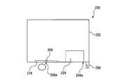
- the cover 202 of the machine tool 200 has first and second openings 212 and 214.
- the first and second openings 212 and 214 are formed from the same side wall on the front side of the cover 202 to the upper wall.
- the first opening 212 leads to the machined area
- the second opening 214 leads to the space in which the peripheral device is arranged.
- the first and second doors 204, 206 By opening the first and second doors 204, 206, the operator has access to the machining area and the space where the peripherals are located.
- the first and second doors 204 and 206 can also be plate-shaped or shutter-shaped sliding doors or rotating doors, similar to the first and second doors 104 and 106 of FIGS. 1 and 2.
- one distance sensor 208 is attached to the side wall where the first and second doors 204 and 206 are arranged as a sensor for measuring the movement of an object close to the opening. ing.
- the distance sensor 208 is a distance sensor similar to the first and second distance sensors 108 and 110 in the first and second embodiments of FIGS. 1 and 2.
- a plurality of machine tools can be connected to the process control device 10 to form a production system.
- four machine tools 100-1, 100-2, 100-3, 100-4 are connected to one process control device 10.
- the processing result by the process control device 10 is displayed on the display (display device) 50.
- the display 50 is not a single display device, but may be a plurality of display devices installed at a plurality of locations in the factory.
- the display device can be a liquid crystal display of a personal computer or a tablet.
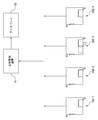
- the process control device 10 includes an input unit 12, a determination unit 14, an RTC 16 including an integrated circuit equipped with a clock function, a storage unit 18, and an output unit 20 as main components.
- the process control device 10 includes a CPU (central computing element), a memory device such as RAM (random access memory) and ROM (read-only memory), and a storage device such as HDD (hard disk drive) and SSD (solid state drive). It can consist of a computer and related software that includes input and output ports and a two-way bus that interconnects them.
- a plurality of machine tools 100-1, 100-2, 100-3, and 100-4 are connected to one process control device 10, and the whole is a production system.
- One machine tool may be connected to form one machine tool as a whole.
- the process control device 10 can be incorporated as a part of the machine control device of the machine tool.
- the distance sensors 30-1, 30-2, 30-3, and 30-4 of the machine tools 100-1, 100-2, 100-3, and 100-4 are connected to the input unit 12.
- the distance sensors 30-1, 30-2, 30-3, and 30-4 are the first and second distance sensors 108 and 110 in the case of the embodiments shown in FIGS. 1 and 2, and the distance sensors 30-1, 30-2, 30-3, and 30-4 are shown in FIGS. In the case of the embodiment, it is the distance sensor 208.
- the input unit 12 receives signals from the distance sensors 30-1, 30-2, 30-3, and 30-4, associates the signals with the received distance sensors, and outputs the signals to the determination unit 14.
- the signals from the distance sensors 30-1, 30-2, 30-3, and 30-4 are signals indicating the distance.
- the output signals from the distance sensors 30-1, 30-2, 30-3, and 30-4 are digital signals, they are signals indicating the detected distance itself.
- the output signals from the distance sensors 30-1, 30-2, 30-3, and 30-4 are analog signals, they are signals having an amplitude or intensity proportional to the detected distance.
- the determination unit 14 passes through communication equipment such as a LAN installed in the factory to control devices 40-1, 40-2, respectively, of machine tools 100-1, 100-2, 100-3, and 100-4. It is connected to 40-3 and 40-4.
- the control devices 40-1, 40-2, 40-3, 40-4 include NC devices and machine control devices of the machine tools 100-1, 100-2, 100-3, 100-4, respectively.
- the determination unit 14 reads the machining program read and interpreted by the control devices 40-1, 40-2, 40-3, and 40-4, respectively, of the control devices 40-1, 40-2, 40-3, and 40-4. Receive from. At the same time, the determination unit 14 receives the current time from the RTC 18.
- the storage unit 18 is based on the change in the distance detected by the distance sensors 30-1, 30-2, 30-3, and 30-4, and the storage units 18 are the machine tools 100-1, 100-2, 100-3, 100-4.
- the rule or judgment standard for classifying the non-processing time which is the time when is not processed, into the setup time in which the operator is performing the setup operation work and the other wasted time (idle) time is stored. .. Further, the determination result by the determination unit 14 may be stored in the storage unit 18.
- the output unit 20 is a VGA (D-Sub15 pin) terminal (analog output terminal), a DVI terminal, an HDMI (registered trademark) terminal, or a display port (registered trademark) terminal for outputting the processing result by the determination unit 14 or the determination result to the display 50. It can be a DisplayPort) terminal (digital output terminal) or a wired or wireless LAN port for connecting to a portable electronic device such as a personal computer or tablet other than the process control device 10.
- VGA D-Sub15 pin
- HDMI registered trademark
- display port registered trademark
- the determination unit 14 uses the control devices 40-1, 40-2, 40-3. , 40-4 receives the machining program, RTC16 receives the current time, and machine tools 100-1, 100-2, 100-3, 100-4 are not machining based on the machining program and the current time.
- the time is output to the storage unit 18 as the non-processing time.
- the determination unit 14 determines whether or not the distance detected by the distance sensors 30-1, 30-2, 30-3, and 30-4 is within a predetermined range at least during the non-processing time (step S10).
- the distances detected by the distance sensors 30-1, 30-2, 30-3, and 30-4 are the first and second doors 104 and 106 (first and second openings) in the first and second embodiments of FIGS. This is the distance between the object and the distance sensors 108 and 110 when some object is present in front of the side wall on which the portions 112 and 114) are arranged. And the distance between the object and the distance sensor 208 if any object is present in front of the side wall on which the second doors 204, 206 (first and second openings 212, 214) are located. Is.
- the predetermined range is between the first and second distance sensors 108 and 110 and the first and second doors 104 and 106 constituting the distance sensors 30-1, 30-2, 30-3 and 30-4. It is determined in consideration of the distance (the embodiment of FIGS. 1 and 2) and the distance between the distance sensor 208 and the first and second doors 204 and 206 (the embodiment of FIGS. 3 and 4). As an example, in the embodiments of FIGS. 1 and 2, the predetermined range can be 600 to 1200 mm, and in the embodiments of FIGS. 3 and 4, it can be 1800 to 2400 mm. In the space in front of the side wall where the first and second doors 104, 106 (FIGS. 1 and 2); 204, 206 (FIGS. 3 and 4) are arranged, the first and second doors are parallel to the side wall.
- the predetermined range measured from the distance sensors 108, 110 and the distance sensor 208 is set as the region of interest.
- step S10 If the distance detected by the distance sensors 30-1, 30-2, 30-3, 30-4 is not within the predetermined range (No in step S10), the object is the first and second doors 104, 106 or Since it can be determined that the doors 204 and 206 do not exist in front of the first and second doors 204 and 206, and therefore at least the operator has not performed the setup work, the process proceeds to step S20 and the non-setup time is determined. If the distance detected in step S10 is within a predetermined range (Yes in step S10), the process proceeds to step S12, and it is determined whether or not the fluctuation of the distance is detected.
- step S12 If there is no change in the distance detected by the distance sensors 30-1, 30-2, 30-3, 30-4 (No in step S12), the first and second doors 104, 106 (FIGS. 1 and 2). ); Since the object existing in the region of interest in front of 204 and 206 (FIGS. 3 and 4) is not moving, that is, it is inanimate and not an operator, the process proceeds to step S20, and it is determined that the non-setup time is set. Step S20).
- step S14 it is determined whether or not the magnitude of the variation is equal to or greater than a predetermined value.
- a predetermined value can be, for example, 20 mm.
- step S16 it is determined in step S16 whether or not the fluctuation of such a distance continues for a predetermined time (first predetermined time) or more. This is to eliminate, for example, the case where the operator passes through the region of interest by walking. This predetermined time can be, for example, 60 seconds. If No in step S16, the operator has not performed the setup work, so the process proceeds to step S20 and the non-setup time is determined. In the case of Yes in step S16, it is determined that the person is continuously moving in the region of interest, that is, the setup work is being performed (step S24).
- step S14 the distance between the object in the region of interest and 30-1, 30-2, 30-3, 30-4 is fluctuating, so that the object is It is judged to be a human being (operator) rather than a mere object, but its distance fluctuation is small, and the operator in the area of interest is practically not moving, so it is basically not doing any work. It is determined that it is a non-setup time.
- second predetermined time the distance fluctuation smaller than the predetermined value continues for a predetermined time (second predetermined time) or longer (Yes in step S18)
- the operator in the region of interest remains substantially stationary. It is determined that the operator has fallen and is fainted, for example, and it is determined that the operator is abnormal (step S22).
- the corresponding control devices 40-1, 40-2, 40-3, 40-4 can be instructed to issue an alert. If No in step S18, it is determined that the non-setup time, that is, the wasted (idle) time (step S20).
- a graph as shown in FIG. 8 can be displayed on the display 50.
- the graph shown in FIG. 8 includes icons 62, 64, 66 indicating each machine tool and bar graphs 70, 72, 74 drawn along the time axis 68.
- the bar graphs 70, 72, and 74 can be displayed according to the type of machine tool state such as machining time A, wasted (idle) time B, setup time C, stop time D, maintenance time E, and hold time F.
- the operator of the process control device 10 can input and specify the start date and time and the end date and time of the bar graphs 70, 72, and 74 to be displayed.
- the machining time A is the time during which the related machine tool is machining, and the process control device 10 can be obtained by communicating with the control device of each machine tool, particularly the machine control device. More specifically, the machining time A is described in the machining program read and interpreted by the NC device of each machine tool, for example, at the start and end of machining such as the rotation start code and stop code of the spindle.
- a related code (for example, G code) can be read and a calculation can be performed based on the information from the RTC 16.
- the wasted time B is the time during which the related machine tool is not machining, excluding the setup time C, the stop time D, the maintenance time E, the hold time F, and the like.
- the setup time C is a time calculated by the process management device 10 according to the flowchart shown in FIG.
- the stop time D is the time when the power of the related machine tool is turned off, and the process control device 10 cannot communicate with the control devices 40-1, 40-2, 40-3, 40-4 of each machine tool. This is the time excluding the maintenance time E and the hold time F.
- Maintenance time E is the time during which machine tool maintenance and repairs are performed.
- the maintenance time E is, for example, the maintenance start date and time when the operator inputs "maintenance start operation" and “maintenance end operation” from the operation panel (not shown) of each machine tool during maintenance or repair of the machine tool. And the maintenance end date and time are input to the control device (machine control device), and the process control device 10 is set. It can be obtained by reading it.
- the hold time F is the time during which the running machining program is temporarily stopped by the operator pressing the hold button of the machine tool. While the machining program is paused, the operator executes the machining program line by line to verify the machining program and observe the inside of the machining room to check the machining status. After the confirmation by the operator is completed, the pause can be released and the machining can be restarted.
- the setup time C which is the time during which the machine tool is not processing, is extracted.
- the setup is performed.
- the time C can be further divided into, for example, a work carry-in time, a work carry-out time, and a work position adjustment time.
- the subroutine of FIG. 9 can be executed in parallel with the subroutine of FIG.
- 0 zero
- step S30 it is first input to the flag i (step S30).
- step S32 it is determined whether or not the following first condition I is satisfied and "work loading / unloading" is not input to the variable C (0).
- the first condition I is to detect an object within the predetermined range described above and maintain a state in which the change in the distance to the detected object is 150 mm or less for 1 minute.
- the predetermined range can be 600 to 1200 mm in the embodiments of FIGS. 1 and 2, and 1800 to 2400 mm in the embodiments of FIGS. 3 and 4.
- the first condition I is a condition for extracting a case where the operation of the operator in the region of interest is relatively small and the operator is carrying out or carrying in the work.
- step S32 that is, when the first condition I is satisfied and "work loading / unloading" is not input to the variable C (0), "work loading / unloading" is entered in the variable C (i) in step S34. Is input, 1 is added to the flag i, and the flow proceeds to step S36. If No in step S32, that is, if the first condition I is not satisfied (the operator's operation is relatively large) or if "work loading / unloading" has already been input to the variable C (0), the flow is step S36. Proceed to.
- step S36 it is determined whether or not the following second condition II is satisfied and "work position adjustment" is not input to the variable C (0).
- the second condition II is that the object is detected in the predetermined range and the distance changes over 150 mm three times in one minute.
- the second condition II is a condition for extracting the case where the operation of the operator in the region of interest is relatively large and frequent, and the operator is adjusting the position of the work.
- step S36 that is, the second condition II is not satisfied (the operator's operation is relatively small or the frequency of large operation is low), or the variable C (0) is already set to "work position" in step S38. If “adjustment” is input, the flow proceeds to step S40.
- step S42 when "work loading / unloading" is input to the variable C (0) and "work position adjustment” is input to the variable C (1) (Yes in step S42), the first and second It is considered that the detection result by the distance sensors 108, 110 or the distance sensor 208 of the above reflects that the position of the work has been adjusted after the work has been carried in. Therefore, the setup time is determined to be the work carry-in time (step S44). ), The flow proceeds to step S46. On the contrary, even if No in step S42, the flow proceeds to step S46.
- step S42 If No in step S42, "work position adjustment” is input to the variable C (0), and “work loading / unloading” is input to the variable C (1) (Yes in step S46). And the detection result by the second distance sensor 108, 110 or the distance sensor 208 is considered to reflect that the work has been carried out after the position adjustment of the work, so that the setup time is determined to be the work position adjustment time. (Step S48), 0 (zero) is input to the variables C (0) and C (1) in step S50, and the subroutine ends. In the case of No in step S46, that is, in the case of Yes in step S42, the flow proceeds to step S50, 0 (zero) is input to the variables C (0) and C (1), and the subroutine ends.
- the setup time C can be further divided into, for example, the work loading time, the work unloading time, and the work position adjustment time.
- Process control device 12 Input unit 14 Judgment unit 18 Storage unit 20 Output unit 30 Distance sensor 40 Control device 50 Display 100 Machine machine 102 Cover 104 First door 104a Door handle 106 Second door 106a Door handle 108 First distance Sensor 110 Second distance sensor 112 First opening 114 Second opening
Landscapes
- Engineering & Computer Science (AREA)
- Mechanical Engineering (AREA)
- Physics & Mathematics (AREA)
- Optics & Photonics (AREA)
- Manufacturing & Machinery (AREA)
- General Physics & Mathematics (AREA)
- Business, Economics & Management (AREA)
- Economics (AREA)
- Primary Health Care (AREA)
- Health & Medical Sciences (AREA)
- Human Computer Interaction (AREA)
- General Health & Medical Sciences (AREA)
- Human Resources & Organizations (AREA)
- Marketing (AREA)
- Automation & Control Theory (AREA)
- Strategic Management (AREA)
- Tourism & Hospitality (AREA)
- General Business, Economics & Management (AREA)
- Theoretical Computer Science (AREA)
- Numerical Control (AREA)
- Multi-Process Working Machines And Systems (AREA)
- General Factory Administration (AREA)
Abstract
工作機械が、ワークを搬入する開口部の近傍に配置され、開口部に近接した対象の動きを計測するセンサ(30-1, 30-2, 30-3, 30-4)と、センサに対する対象の動きに基づいて、非加工時間を段取り時間と非段取り時間に区分するための規則を格納した記憶部(18)と、加工プログラムが実行されていないときに、対象の動きと記憶部に格納した規則に基づいて、工作機械の現在の状態が、段取り時間であるか非段取り時間であるかを判定する判定部(14)と、工作機械の現在の状態が段取り時間であるか、非段取り時間であるかを出力する出力部(20)とを具備する。
Description
本発明は、工作機械が加工を行っていない時間である非加工時間の内訳が分かるようにした工作機械および生産システムに関する。
工作機械の個々のプロセスに要する時間を正確に管理することは、スケジューリングの精度や、製造コストの見積もりの精度を高めるため、また生産性を改善するために必要である。特許文献1には、複数の設備の稼働実績の表示,分析を行う稼働実績表示分析システムが記載されている。
工作機械が加工を行っていない非加工時間は、単に工作機械が停止している無駄(アイドル)時間だけではなく、オペレータがワークの搬入、工作機械へのワークの位置決め固定、或いは、工作機械からのワークの取り外し、搬出、工具の搬入、搬出等の作業を行う段取り時間をも含んでいる。
この点、特許文献1に記載の稼働実績表示分析システムを含めて従来技術では、段取り時間と無駄時間とを含む非加工時間の内訳を明らかにすることができない問題がある。
本発明は、こうした従来技術の問題を解決することを技術課題としており、工作機械が加工を行っていない非加工時間を段取り時間と無駄時間の内訳を明らかにすることができる工作機械および生産システムを提供することを目的としている。
上述の目的を達成するために、本発明によれば、加工プログラムに基づいてワークを加工する工作機械において、ワークを搬入する開口部の近傍に配置され、開口部に近接した対象の動きを計測するセンサと、前記センサで計測した対象の動きに基づいて、非加工時間を段取り時間と非段取り時間に区分するための規則を記憶した記憶部と、加工プログラムが実行されていないときに、対象の動きと記憶部に記憶した規則に基づいて、工作機械の現在の状態が、段取り時間であるか非段取り時間であるかを判定する判定部と、工作機械の現在の状態が段取り時間であるか、非段取り時間であるかを出力する出力部とを備えた工作機械が提供される。
更に、本発明によれば、加工プログラムに基づいてワークを加工する複数の工作機械により製品を生産する生産システムにおいて、ワークを搬入する開口部の近傍に、開口部に近接した対象の動きを計測するセンサが配置された複数の工作機械と、前記センサで計測した対象の動きに基づいて、非加工時間を段取り時間と非段取り時間に区分するための規則を記憶した記憶部と、加工プログラムが実行されていないときに、対象の動きと記憶部に記憶した規則に基づいて、工作機械の状態が、段取り時間であるか非段取り時間であるかを判定する判定部と、工作機械の状態が段取り時間であるか、非段取り時間であるかを出力する出力部とを有し、各工作機械の工程を管理する工程管理装置と、前記送信部から送信された工作機械の状態に基づいて、段取り時間を時間軸に沿って表示するディスプレイとを備えた生産システムが提供される。
本発明によれば、工作機械または生産システムを構成する各工作機械の段取り時間と無駄時間とを含む非加工時間の内訳を明らかになり、生産スケジューリングおよび製造コストの見積もりを精度よく行うことが可能となり、また生産性を高めることが可能となる。
以下、添付図面を参照して、本発明の好ましい実施形態を説明する。
図1に、本発明を適用する工作機械の一例を示す。図1において、工作機械100は、加工プログラムに従いワークを加工する放電加工機(図示せず)やマシニングセンタ(図示せず)のような加工機と、加工機のための周辺機器を包囲するカバー102を備えている。周辺機器は、電極マガジン(図示せず)や工具マガジン(図示せず)、自動電極交換装置(図示せず)や自動工具交換装置(図示せず)、放電加工用の加工液供給装置やマシニングセンタ用の切削液供給装置等が含まれる。
図1に、本発明を適用する工作機械の一例を示す。図1において、工作機械100は、加工プログラムに従いワークを加工する放電加工機(図示せず)やマシニングセンタ(図示せず)のような加工機と、加工機のための周辺機器を包囲するカバー102を備えている。周辺機器は、電極マガジン(図示せず)や工具マガジン(図示せず)、自動電極交換装置(図示せず)や自動工具交換装置(図示せず)、放電加工用の加工液供給装置やマシニングセンタ用の切削液供給装置等が含まれる。
工作機械100は、ワークを固定するためのテーブル(図示せず)、電極や回転工具を装着する主軸(図示せず)、テーブルと主軸とを少なくとも直交3軸方向に相対送りする送り軸装置(図示せず)、送り軸装置を加工プログラムに従い制御するためのNC装置(図示せず)および送り軸装置を除く加工機の機能および周辺機器を制御する機械制御装置(図示せず)を含む。
カバー102は、第1と第2の開口部112、114を有している。第1の開口部112は、カバー102の正面側の側壁から上壁にかけて形成されている。第1の開口部112は加工領域に通じており、第1の開口部112によって、オペレータはカバー102内の加工機の加工領域にアクセス可能となる。加工領域は、ワークが加工機のテーブル上に配置、固定され、工具としての細孔電極や総形電極のような電極(図示せず)や、エンドミルのような回転工具(図示せず)によって加工される空間である。
第2の開口部は、第1の開口部112が形成されているカバー102の正面側の側壁とは別の側壁、図1、2の実施形態では、正面側の側壁に対して垂直に結合された正面から見て左側の側壁に形成されている。第2の開口部114は、カバー102内において、電極マガジン(図示せず)や工具マガジン(図示せず)のような周辺機器が配置されている空間に通じており、第2の開口部114によって、オペレータは、これらの機器にアクセス可能となる。
電極マガジンには、電極ホルダ(図示せず)に装着された多数の電極が収納され、自動電極交換装置によって、放電加工機の主軸の先端に装着された使用済み電極と交換される。工具マガジンには、工具ホルダに装着された多数の工具が収納されている。加工プログラムに従い、次工程で使用される工具が選択され、自動工具交換装置によって、マシニングセンタの回転主軸の装着されている工具と交換される。
カバー102は、また、第1と第2の開口部112、114を開放、閉鎖する第1と第2のドア104、106を有している。第1のドア104は、第1の開口部112が形成されているカバー102の正面側の側壁および上壁に沿って水平方向にスライド可能にカバー102に取り付けられている。第2のドア106は、第2の開口部114が形成されている側壁に沿って水平方向にスライド可能にカバー102に取り付けられている。第1と第2のドア104、106は、水平方向以外に上下方向にスライドするようになっていてもよい。また、第1と第2のドア104、106は、典型的には板状のドアであるが、鎧戸状のドアであってもよい。
第1と第2のドア104、106は、蝶番によってカバー102の側壁に回転可能に取り付けられた回転ドアとしてもよい。但し、第1と第2のドア104、106を回転ドアとする場合には、後述する、レーダ式距離センサが発する電波を妨害しないように、回転ドアを開いたときに側壁に重ね合わせることができるようにする必要がある。
オペレータは、図2に示すように、第1のドア104の正面に立って、ドアハンドル104aを把持し、第1のドア104を左方(図2においても左方)へスライドさせて第1のドア104を開き、第1の開口部112を通して加工領域にアクセス可能となる。こうして、オペレータは、加工済ワーク(図示せず)をテーブルから取り外して搬出したり、未加工ワーク(図示せず)を搬入してテーブルに位置決め、固定する等の段取り作業を行うことができる。
同様に、オペレータは、第2のドア106の正面に立って、ドアハンドル106aを把持し、第2のドア106を右方(図2では下方)へスライドさせて第2のドア106を開き、第2の開口部114を通して電極マガジンや工具マガジンのような周辺機器へアクセス可能となる。こうして、オペレータは、使用済電極(図示せず)を電極マガジンから取り外し、未使用電極(図示せず)を電極マガジンの所定位置に装着したり、破損または摩耗した工具(図示せず)を工具マガジンから取り外し、新規の工具を工具マガジンに装着したり、或いは、これから行う工具を工具マガジンに装着、準備する等の段取り作業を行うことができる。
カバー102には、また、開口部に近接した対象の動きを計測するセンサとして、第1と第2の距離センサ108、110が配設されている。第1と第2の距離センサ108、110は、好ましくは、図1、2に示すように、カバー102において、第1と第2のドア104、106が配設されている側壁に取り付けられる。第1の距離センサ108は、第1のドア104が配設されている側壁の前にある物体と、該第1の距離センサ108との間の距離を測定する距離センサであり、好ましくは、非接触式バイタルセンサに用いられる高精度レーダである。第2の距離センサ110は、第2のドア106が配設されている側壁の前にある物体と、第2の距離センサ110との間の距離を測定する距離センサであり、好ましくは、非接触式バイタルセンサに用いられる高精度レーダである。
図1、2に示す実施形態では、第1と第2のドア104、106は、異なる側壁に取り付けられているが、図3、4に示すように、同一の側壁に取り付けられていてもよい。図3、4において、工作機械200のカバー202は、第1と第2の開口部212、214を有している。第1と第2の開口部212、214は、カバー202の正面側の同じ側壁から上壁にかけて形成されている。第1の開口部212は加工領域に通じており、第2の開口部214は、周辺機器が配置されている空間に通じている。第1と第2のドア204、206を開くことによって、オペレータは加工領域および周辺機器が配置されている空間にアクセス可能となる。第1と第2のドア204、206も、図1、2の第1と第2のドア104、106と同様に、板状または鎧戸状のスライドドアまたは回転ドアとすることができる。
本実施形態では、カバー102において、第1と第2のドア204、206が配設されている側壁に、開口部に近接した対象の動きを計測するセンサとして、1つの距離センサ208が取り付けられている。距離センサ208は、図1、2の実施形態における第1と第2の距離センサ108、110と同様の距離センサである。
本発明では、複数の工作機械を工程管理装置10に接続して生産システムを構成することができる。図5を参照すると、4台の工作機械100-1、100-2、100-3、100-4が、1つの工程管理装置10に接続されている。また、工程管理装置10による処理結果はディスプレイ(表示装置)50に表示される。ディスプレイ50は1つの表示装置ではなく、工場内の複数個所に設置された複数の表示装置としてもよい。表示装置は、パーソナルコンピュータやタブレットの液晶ディスプレイとすることができる。
図6を参照すると、工程管理装置10は、入力部12、判定部14、時計機能を実装した集積回路より成るRTC16、記憶部18、出力部20を主要な構成要素として具備している。工程管理装置10は、CPU(中央演算素子)、RAM(ランダムアクセスメモリ)やROM(リードオンリーメモリ)のようなメモリ装置、HDD(ハードディスクドライブ)やSSD(ソリッドステートドライブ)のような記憶デバイス、出入力ポート、および、これらを相互接続する双方向バスを含むコンピュータおよび関連するソフトウェアから構成することができる。
図5では、1つの工程管理装置10に複数の工作機械100-1、100-2、100-3、100-4を接続して、全体を生産システムとしているが、1つの工程管理装置10に1台の工作機械を接続して全体を1つの工作機械としてもよい。この場合には、工程管理装置10は、工作機械の機械制御装置の一部として組み込むことができる。
入力部12には、工作機械100-1、100-2、100-3、100-4の各々の距離センサ30-1、30-2、30-3、30-4が接続されている。距離センサ30-1、30-2、30-3、30-4は、図1、2の実施形態の場合には、第1と第2の距離センサ108、110であり、図3、4の実施形態の場合には、距離センサ208である。
入力部12は、距離センサ30-1、30-2、30-3、30-4からの信号を受信し、該信号を受信した距離センサと関連付けて、判定部14へ出力する。距離センサ30-1、30-2、30-3、30-4からの信号は距離を示す信号である。距離センサ30-1、30-2、30-3、30-4からの出力信号がデジタル信号である場合には、検出した距離そのものを示す信号である。距離センサ30-1、30-2、30-3、30-4からの出力信号がアナログ信号である場合には、検出した距離に比例した振幅または強度の信号である。
判定部14は、工場内に付設されているLANのような通信設備を通して、工作機械100-1、100-2、100-3、100-4の各々の制御装置40-1、40-2、40-3、40-4に接続されている。制御装置40-1、40-2、40-3、40-4は、各工作機械100-1、100-2、100-3、100-4のNC装置および機械制御装置を含む。判定部14は、制御装置40-1、40-2、40-3、40-4が、読み取り、解釈した加工プログラムを制御装置40-1、40-2、40-3、40-4の各々から受け取る。同時に、判定部14はRTC18から現在時刻を受け取る。
記憶部18は、距離センサ30-1、30-2、30-3、30-4が検知した距離の変化に基づいて、各工作機械100-1、100-2、100-3、100-4が加工していない時間である非加工時間を、オペレータが段取り作用業を行っている段取り時間と、それ以外の無駄時間(アイドル)時間とに区分するための規則または判定基準が記憶されている。また、判定部14による判定結果を記憶部18に記憶させてもよい。
出力部20は、判定部14による処理結果または判定結果をディスプレイ50に出力するためのVGA(D-Sub15ピン)端子(アナログ出力端子)や、DVI端子、HDMI(登録商標)端子またはディスプレイポート(DisplayPort)端子(デジタル出力端子)、或いは、工程管理装置10以外のパーソナルコンピュータやタブレットのような携帯電子機器に接続するための有線または無線のLANポートとすることができる。
以下、図7、8を参照して、上記実施形態の作用を説明する。
工作機械100-1、100-2、100-3、100-4が起動している間、つまり電源が入っている間、判定部14は、制御装置40-1、40-2、40-3、40-4から加工プログラムを受け取り、RTC16から現在時刻を受け取り、加工プログラムと現在時刻とに基づいて、工作機械100-1、100-2、100-3、100-4が加工を行っていない時間を非加工時間として記憶部18へ出力する。判定部14は、少なくとも非加工時間中、距離センサ30-1、30-2、30-3、30-4が検出した距離が所定範囲にあるか否かを判定する(ステップS10)。
工作機械100-1、100-2、100-3、100-4が起動している間、つまり電源が入っている間、判定部14は、制御装置40-1、40-2、40-3、40-4から加工プログラムを受け取り、RTC16から現在時刻を受け取り、加工プログラムと現在時刻とに基づいて、工作機械100-1、100-2、100-3、100-4が加工を行っていない時間を非加工時間として記憶部18へ出力する。判定部14は、少なくとも非加工時間中、距離センサ30-1、30-2、30-3、30-4が検出した距離が所定範囲にあるか否かを判定する(ステップS10)。
距離センサ30-1、30-2、30-3、30-4が検出する距離は、図1、2の実施形態では、第1と第2のドア104、106(第1と第2の開口部112、114)が配設されている側壁の前に何らかの物体が存在する場合に、該物体と距離センサ108、110との間の距離であり、図3、4の実施形態では、第1と第2のドア204、206(第1と第2の開口部212、214)が配設されている側壁の前に何らかの物体が存在する場合に、該物体と距離センサ208との間の距離である。
所定範囲は、距離センサ30-1、30-2、30-3、30-4を構成する第1と第2の距離センサ108、110と第1と第2のドア104、106との間の距離(図1、2の実施形態)、距離センサ208と第1と第2のドア204、206との間の距離(図3、4の実施形態)を勘案して決定される。一例として、図1、2の実施形態では、所定範囲は600~1200mmとすることができ、図3、4の実施形態では、1800~2400mmとすることができる。第1と第2のドア104、106(図1、2);204、206(図3、4)が配設されている側壁の前の空間において、該側壁に平行に第1と第2の距離センサ108、110および距離センサ208から測定した上記所定範囲を関心領域とする。
距離センサ30-1、30-2、30-3、30-4が検出した距離が所定範囲内にない場合(ステップS10でNoの場合)、物体が第1と第2のドア104、106または第1と第2のドア204、206の前に存在しないと判断でき、従って、少なくともオペレータが段取り作業を行っていることはないので、ステップS20へ進み非段取り時間と判定される。ステップS10で検出した距離が所定範囲内にある場合(ステップS10でYesの場合)、ステップS12に進み、距離の変動が検出されるか否かが判定される。
距離センサ30-1、30-2、30-3、30-4が検出した距離に変動がなければ(ステップS12でNoの場合)、第1と第2のドア104、106(図1、2);204、206(図3、4)の前の関心領域内に存在する物体は動いていない、つまり無生物であって、オペレータではないので、ステップS20へ進み、非段取り時間と判定される(ステップS20)。
ステップS12で検出した距離に変動がある場合、ステップS14へ進み、変動の大きさが所定値以上であるか否かが判定される。一般的に、人間は完全に静止していることはできず、じっとしていて一見静止しているように見えても、例えば、拍動その他の影響から実際には身体はゆらいでいる。そこで、ステップS14では、検出した変動する距離のうち、所定値未満の距離の変動は、こうした人体の揺らぎによるものであるとして、それを除去することによって、人(オペレータ)が作業をしているか否かを判定するようにしている。所定値は、例えば20mmとすることができる。
ステップS14でYesの場合、ステップS16で、そうした距離の変動が所定時間(第1の所定時間)以上継続しているか否かが判定される。これは、例えば、オペレータが、歩行によって関心領域を通過するような場合を除去するためである。この所定時間は、例えば60秒とすることができる。ステップS16でNoの場合、オペレータが段取り作業を行っていることはないので、ステップS20へ進み非段取り時間と判定される。ステップS16でYesの場合、人が関心領域内で継続して動いている、つまり段取り作業をしていると判定される(ステップS24)。
ステップS14でNoの場合は、上述したように、関心領域内にある物体と30-1、30-2、30-3、30-4との間の距離は変動しているので、該物体は単なる物ではなく人間(オペレータ)であると判定されるが、その距離変動は小さく、関心領域内のオペレータは、実質的に動いておらず、従って何らかの作業をしているのではなく、基本的に非段取り時間であると判定される。然しながら、ここで、所定値よりも小さな距離変動が、所定時間(第2の所定時間)以上継続する場合(ステップS18でYes)、つまり関心領域内にいるオペレータは、実質的に動かないままじっとしていると判定され、これは、例えばオペレータが倒れて気を失っているような場合が想定され、オペレータ異常と判定される(ステップS22)。この場合、対応する制御装置40-1、40-2、40-3、40-4にアラートを発するように指令するようにできる。ステップS18でNoの場合は、非段取り時間すなわち無駄(アイドル)時間と判定される(ステップS20)。
上述のように、本実施形態によれば、工作機械が加工を行っていない非加工時間から、オペレータが段取り作業を行っている時間(段取り時間)を抽出することができる。これに基づいて、例えば、図8に示すようなグラフをディスプレイ50に表示することができる。図8に示すグラフは、各工作機械を示すアイコン62、64、66と、時間軸68に沿って描かれた棒グラフ70、72、74を含む。棒グラフ70、72、74は、加工時間A、無駄(アイドル)時間B、段取り時間C、停止時間D、保守時間E、ホールド時間F等の工作機械の状態の種別で表示することができる。時間軸68は、表示すべき棒グラフ70、72、74の開始日時と終了日時を工程管理装置10のオペレータが入力、指定するようにできる。
加工時間Aは、関連する工作機械が加工を行っている時間であり、工程管理装置10は、各工作機械の制御装置、特に、機械制御装置と通信することによって得ることができる。より詳細には、加工時間Aは、例えば、各工作機械のNC装置が読み取り、解釈した加工プログラムに記載されている、例えば主軸の回転開始コードおよび停止コードのような、加工の開始、終了に関連したコード(例えばGコード)を読み取るとともに、RTC16からの情報に基づいて演算することができる。
無駄時間Bは、関連する工作機械が加工を行っていない時間のうち、段取り時間C、停止時間D、保守時間Eおよびホールド時間F等を除いた時間である。段取り時間Cは、工程管理装置10により図7に示すフローチャートに従い演算された時間である。停止時間Dは、関連する工作機械の電源がOFFされていた時間であり、工程管理装置10が、各工作機械の制御装置40-1、40-2、40-3、40-4と通信不能となっている時間のうち、保守時間Eとホールド時間Fを除いた時間である。
保守時間Eは、工作機械のメンテナンスや修理を行っている時間である。保守時間Eは、例えば、工作機械のメンテナンスや修理に際して、オペレータが、各工作機械の操作盤(図示せず)から「保守開始操作」と「保守終了操作」を入力することによって、保守開始日時と保守終了日時が制御装置(機械制御装置)に入力され、工程管理装置10が。それを読み取ることによって得ることができる。
ホールド時間Fは、オペレータが工作機械のホールドボタンを押したことにより、実行中の加工プログラムを一時的に停止させている時間である。加工プログラムを一時停止している間に、オペレータは加工プログラムを1行ずつ実行して加工プログラムの検証をしたり、加工状態の確認をするため加工室の中を観察したりする。オペレータによる確認が終わった後は、一時停止を解除して加工を再開することができる。
なお、上記の実施形態では、オペレータが段取り作業を行っているために、工作機械が加工を行っていない時間である段取り時間Cを抽出するようになっているが、本発明によれば、段取り時間Cは、更に詳細に、例えばワークの搬入時間、ワーク搬出時間およびワーク位置調整時間に分けることができる。
図9のサブルーチンは、図7のサブルーチンと同時並行的に実行することができる。
図9のサブルーチンが開始されると、まずフラグiに0(零)が入力される(ステップS30)。次いで、ステップS32おいて、以下の第1条件Iが満たされ、かつ、変数C(0)に「ワーク搬出入」が入力されていないか否かが判定される。ここで、第1条件Iは、上述した所定範囲に物体を検出し、かつ、検出した物体までの距離の変化が150mm以下の状態を1分間維持することである。所定範囲は、上述したように、図1、2の実施形態では、600~1200mmとすることができ、図3、4の実施形態では、1800~2400mmとすることができる。第1条件Iは、関心領域内にいるオペレータの動作が比較的小さい場合であって、オペレータがワークの搬出または搬入を行っている場合を抽出する条件である。
図9のサブルーチンが開始されると、まずフラグiに0(零)が入力される(ステップS30)。次いで、ステップS32おいて、以下の第1条件Iが満たされ、かつ、変数C(0)に「ワーク搬出入」が入力されていないか否かが判定される。ここで、第1条件Iは、上述した所定範囲に物体を検出し、かつ、検出した物体までの距離の変化が150mm以下の状態を1分間維持することである。所定範囲は、上述したように、図1、2の実施形態では、600~1200mmとすることができ、図3、4の実施形態では、1800~2400mmとすることができる。第1条件Iは、関心領域内にいるオペレータの動作が比較的小さい場合であって、オペレータがワークの搬出または搬入を行っている場合を抽出する条件である。
ステップS32でYesの場合、つまり、第1条件Iを満たし、かつ、変数C(0)に「ワーク搬出入」が入力されていない場合、ステップS34で変数C(i)に「ワーク搬出入」が入力されるとともに、フラグiに1が加算され、フローはステップS36へ進む。ステップS32でNoの場合、つまり、第1条件Iを満たさない(オペレータの動作が比較的大きい)か、既に変数C(0)に「ワーク搬出入」が入力されている場合、フローはステップS36へ進む。
ステップS36では、以下の第2条件IIが満たされ、かつ、変数C(0)に「ワーク位置調整」が入力されていないか否かが判定される。ここで、第2条件IIは、上記所定範囲に物体を検出し、かつ、1分間で150mmを超える距離の変化が3回あることである。第2条件IIは、関心領域内にいるオペレータの動作が比較的大きくかつ頻度が高い場合であって、オペレータがワークの位置調整を行っている場合を抽出する条件である。
また、フローチャートがステップS36へ進んだとき、変数C(0)には、(1)何も入力されていない(つまりC(0)=0である)か、(2)「ワーク搬出入」が入力されているか、或いは、(3)「ワーク位置調整」が入力されている。このとき、変数C(1)には、(1)何も入力されていない(つまりC(1)=0である)か、(2)「ワーク搬出入」が入力されているか、或いは、(3)「ワーク位置調整」が入力されている。
ステップS36でYesの場合、つまり、第2条件IIを満たし(オペレータの動作が比較的大きく、動作の頻度が高い)、かつ、変数C(0)に「ワーク位置調整」が入力されていない(C(0)=0か、或いは、ステップS34で変数C(0)に「ワーク搬出入」が入力されている)場合、ステップS38で変数C(i)に「ワーク位置調整」が入力されるとともに、フラグiに1が加算され、フローはステップS40へ進む。ステップS36でNoの場合、つまり、第2条件IIを満たさない(オペレータの動作が比較的小さいか、または、大きな動作の頻度が低い)か、既にステップS38で変数C(0)に「ワーク位置調整」が入力されている場合、フローはステップS40へ進む。
ステップS40ではフラグiが2以上であるか否かが判定される。ステップS40でNoの場合、つまり、i=0または1の場合、フローは、ステップS32へ帰還する。ステップS40でYesの場合、つまり、i=2の場合(本フローチャートでiは3以上にはならない)、フローはステップS42へ進む。
ステップS42へ進んだとき、i=2であるので、変数C(0)に、ステップS34またはステップS38で、「ワーク搬出入」または「ワーク位置調整」が入力されており、かつ、変数C(1)に、ステップS38またはステップS34で、「ワーク位置調整」または「ワーク搬出入」が入力されている。
ステップS42において、変数C(0)に「ワーク搬出入」が入力され、かつ、変数C(1)に「ワーク位置調整」が入力されている(ステップS42でYes)場合、第1と第2の距離センサ108、110または距離センサ208による検出結果は、ワークの搬入後にワークの位置調整がなされていることを反映したものと考えられるので、当該段取り時間はワーク搬入時間と判定され(ステップS44)、フローはステップS46に進む。反対にステップS42でNoの場合も、フローはステップS46に進む。
ステップS42でNoの場合は、変数C(0)に「ワーク位置調整」が入力され、かつ、変数C(1)に「ワーク搬出入」が入力されており(ステップS46でYes)、第1と第2の距離センサ108、110または距離センサ208による検出結果は、ワークの位置調整後にワークの搬出がなされていることを反映したものと考えられるので、当該段取り時間はワーク位置調整時間と判定され(ステップS48)、ステップS50で変数C(0)、C(1)に0(零)が入力され、サブルーチンが終了する。ステップS46でNoの場合、つまり、ステップS42でYesの場合も、フローはステップS50へ進み、変数C(0)、C(1)に0(零)が入力され、サブルーチンが終了する。
図9のサブルーチンを実行することによって、段取り時間Cは、更に詳細に、例えばワークの搬入時間、ワーク搬出時間およびワーク位置調整時間に区分可能となる。
10 工程管理装置
12 入力部
14 判定部
18 記憶部
20 出力部
30 距離センサ
40 制御装置
50 ディスプレイ
100 工作機械
102 カバー
104 第1のドア
104a ドアハンドル
106 第2のドア
106a ドアハンドル
108 第1の距離センサ
110 第2の距離センサ
112 第1の開口部
114 第2の開口部
12 入力部
14 判定部
18 記憶部
20 出力部
30 距離センサ
40 制御装置
50 ディスプレイ
100 工作機械
102 カバー
104 第1のドア
104a ドアハンドル
106 第2のドア
106a ドアハンドル
108 第1の距離センサ
110 第2の距離センサ
112 第1の開口部
114 第2の開口部
Claims (8)
- 加工プログラムに基づいてワークを加工する工作機械において、
ワークを搬入する開口部の近傍に配置され、開口部に近接した対象の動きを計測するセンサと、
前記センサで計測した対象の動きに基づいて、非加工時間を段取り時間と非段取り時間に区分するための規則を記憶した記憶部と、
加工プログラムが実行されていないときに、対象の動きと記憶部に記憶した規則に基づいて、工作機械の現在の状態が、段取り時間であるか非段取り時間であるかを判定する判定部と、
工作機械の現在の状態が段取り時間であるか、非段取り時間であるかを出力する出力部と、
を備えたことを特徴とする工作機械。 - 工作機械の現在の状態が段取り時間であるか、非段取り時間であるかを工程管理装置に出力する出力部を備えた請求項1に記載の工作機械。
- 前記判定部で判定された工作機械の状態に基づいて、段取り時間を時間軸に沿って表示するディスプレイを備えた請求項1に記載の工作機械。
- 工作機械は、加工機の加工空間を包囲するカバーを有しており、前記開口部は、カバーの側壁において、工作機械のオペレータが加工空間にアクセス可能となる位置に形成された第1の開口部である請求項1に記載の工作機械。
- 工作機械は、加工に使用する複数の工具を記憶した工具マガジンを備えており、カバーの側壁において、工作機械のオペレータが工具マガジンにアクセス可能となる位置に第2の開口部が形成されている請求項4に記載の工作機械。
- 第1と第2の開口部がカバーの同じ側壁に形成されており、センサは該側壁に沿って、第1の開口部または第2の開口部の前にある対象までの距離を測定する請求項5に記載の工作機械。
- 第1と第2の開口部がカバーの異なる側壁に形成されており、センサは、第1の開口部が形成された側壁に沿って、第1の開口部の前にある対象までの距離を測定する第1のセンサと、第2の開口部が形成された側壁に沿って、第2の開口部の前にある対象までの距離を測定する第2のセンサとを備える請求項5に記載の工作機械。
- 加工プログラムに基づいてワークを加工する複数の工作機械により製品を生産する生産システムにおいて、
ワークを搬入する開口部の近傍に、開口部に近接した対象の動きを計測するセンサが配置された複数の工作機械と、
前記センサで計測した対象の動きに基づいて、非加工時間を段取り時間と非段取り時間に区分するための規則を記憶した記憶部と、加工プログラムが実行されていないときに、対象の動きと記憶部に記憶した規則に基づいて、工作機械の状態が、段取り時間であるか非段取り時間であるかを判定する判定部と、工作機械の状態が段取り時間であるか、非段取り時間であるかを出力する出力部とを有し、各工作機械の工程を管理する工程管理装置と、
前記送信部から送信された工作機械の状態に基づいて、段取り時間を時間軸に沿って表示するディスプレイと、
を備えたことを特徴とする生産システム。
Priority Applications (3)
| Application Number | Priority Date | Filing Date | Title |
|---|---|---|---|
| EP20877096.6A EP4047429A4 (en) | 2019-10-18 | 2020-10-16 | MACHINE TOOL AND PRODUCTION SYSTEM |
| CN202080072515.6A CN114555287A (zh) | 2019-10-18 | 2020-10-16 | 机床及生产系统 |
| US17/769,628 US20240227108A9 (en) | 2019-10-18 | 2020-10-16 | Machine tool and production system |
Applications Claiming Priority (2)
| Application Number | Priority Date | Filing Date | Title |
|---|---|---|---|
| JP2019191102A JP6999623B2 (ja) | 2019-10-18 | 2019-10-18 | 工作機械および生産システム |
| JP2019-191102 | 2019-10-18 |
Publications (1)
| Publication Number | Publication Date |
|---|---|
| WO2021075573A1 true WO2021075573A1 (ja) | 2021-04-22 |
Family
ID=75537429
Family Applications (1)
| Application Number | Title | Priority Date | Filing Date |
|---|---|---|---|
| PCT/JP2020/039176 Ceased WO2021075573A1 (ja) | 2019-10-18 | 2020-10-16 | 工作機械および生産システム |
Country Status (5)
| Country | Link |
|---|---|
| US (1) | US20240227108A9 (ja) |
| EP (1) | EP4047429A4 (ja) |
| JP (1) | JP6999623B2 (ja) |
| CN (1) | CN114555287A (ja) |
| WO (1) | WO2021075573A1 (ja) |
Families Citing this family (2)
| Publication number | Priority date | Publication date | Assignee | Title |
|---|---|---|---|---|
| JP7084533B1 (ja) * | 2021-09-06 | 2022-06-14 | Dmg森精機株式会社 | 表示制御装置 |
| JP7246530B1 (ja) | 2022-01-18 | 2023-03-27 | Dmg森精機株式会社 | 工作機械、工作機械の制御方法、および工作機械の制御プログラム |
Citations (6)
| Publication number | Priority date | Publication date | Assignee | Title |
|---|---|---|---|---|
| JPH07251356A (ja) | 1994-03-15 | 1995-10-03 | Fujitsu Ltd | 稼働実績表示分析システム |
| JPH0929809A (ja) * | 1995-07-17 | 1997-02-04 | Fanuc Ltd | 成形機安全装置 |
| JP2010055220A (ja) * | 2008-08-26 | 2010-03-11 | Panasonic Electric Works Co Ltd | 作業支援システム |
| JP2010262627A (ja) * | 2009-04-10 | 2010-11-18 | Omron Corp | 設備運転状態計測装置、設備運転状態計測方法、および制御プログラム |
| JP2013073279A (ja) * | 2011-09-26 | 2013-04-22 | Omron Corp | データ処理装置、データ処理システム、およびデータ処理方法 |
| JP2020187708A (ja) * | 2019-05-17 | 2020-11-19 | Dmg森精機株式会社 | 工作機械、行動種別の判別方法、および、行動種別の判別プログラム |
Family Cites Families (14)
| Publication number | Priority date | Publication date | Assignee | Title |
|---|---|---|---|---|
| US5189624A (en) * | 1989-09-29 | 1993-02-23 | General Electric Company | Intelligent machining workstation operating logic |
| JPH08132331A (ja) * | 1994-11-08 | 1996-05-28 | Nippon Telegr & Teleph Corp <Ntt> | 加工作業ロボット制御方法及び装置 |
| EP0744046B1 (en) * | 1994-11-09 | 2003-02-12 | Amada Company Limited | Intelligent system for generating and executing a sheet metal bending plan |
| IL126752A0 (en) * | 1997-03-15 | 1999-08-17 | Makino Milling Machine | Machine tool control apparatus |
| JP5294451B2 (ja) * | 2008-08-29 | 2013-09-18 | アズビルTaco株式会社 | 着座距離判定方法とその装置 |
| DE102010001518A1 (de) * | 2010-02-02 | 2011-08-04 | DECKEL MAHO Pfronten GmbH, 87459 | Vorrichtung zum Steuern von Betriebsfunktionen einer Werkzeugmaschine |
| JP2012203770A (ja) * | 2011-03-28 | 2012-10-22 | Hitachi Chem Co Ltd | 作業分析システム |
| JP5302371B2 (ja) * | 2011-10-13 | 2013-10-02 | ファナック株式会社 | 工作機械の物理データの表示機能を備えた数値制御装置 |
| CN103506856B (zh) * | 2013-10-11 | 2017-02-08 | 浙江日发精密机械股份有限公司 | 卧式加工中心多工作台自动交换装置 |
| DE102015202915A1 (de) * | 2015-02-18 | 2016-08-18 | Robert Bosch Gmbh | Arbeitsplatz mit Kommunikationseinrichtung für Datenträger |
| US11045916B2 (en) * | 2016-09-09 | 2021-06-29 | Makino Milling Machine Co., Ltd. | Machine tool |
| US11273530B2 (en) * | 2016-11-16 | 2022-03-15 | Makino Milling Machine Co., Ltd. | Machine tool system |
| JP7188880B2 (ja) * | 2017-12-05 | 2022-12-13 | オークマ株式会社 | 工作機械 |
| CN109909787B (zh) * | 2019-04-17 | 2023-12-22 | 浙江金火科技实业有限公司 | 一种加工液压管接件用联机调头车床 |
-
2019
- 2019-10-18 JP JP2019191102A patent/JP6999623B2/ja active Active
-
2020
- 2020-10-16 US US17/769,628 patent/US20240227108A9/en not_active Abandoned
- 2020-10-16 WO PCT/JP2020/039176 patent/WO2021075573A1/ja not_active Ceased
- 2020-10-16 CN CN202080072515.6A patent/CN114555287A/zh active Pending
- 2020-10-16 EP EP20877096.6A patent/EP4047429A4/en not_active Withdrawn
Patent Citations (6)
| Publication number | Priority date | Publication date | Assignee | Title |
|---|---|---|---|---|
| JPH07251356A (ja) | 1994-03-15 | 1995-10-03 | Fujitsu Ltd | 稼働実績表示分析システム |
| JPH0929809A (ja) * | 1995-07-17 | 1997-02-04 | Fanuc Ltd | 成形機安全装置 |
| JP2010055220A (ja) * | 2008-08-26 | 2010-03-11 | Panasonic Electric Works Co Ltd | 作業支援システム |
| JP2010262627A (ja) * | 2009-04-10 | 2010-11-18 | Omron Corp | 設備運転状態計測装置、設備運転状態計測方法、および制御プログラム |
| JP2013073279A (ja) * | 2011-09-26 | 2013-04-22 | Omron Corp | データ処理装置、データ処理システム、およびデータ処理方法 |
| JP2020187708A (ja) * | 2019-05-17 | 2020-11-19 | Dmg森精機株式会社 | 工作機械、行動種別の判別方法、および、行動種別の判別プログラム |
Non-Patent Citations (1)
| Title |
|---|
| See also references of EP4047429A4 |
Also Published As
| Publication number | Publication date |
|---|---|
| EP4047429A1 (en) | 2022-08-24 |
| JP6999623B2 (ja) | 2022-01-18 |
| US20240131649A1 (en) | 2024-04-25 |
| JP2021068022A (ja) | 2021-04-30 |
| CN114555287A (zh) | 2022-05-27 |
| US20240227108A9 (en) | 2024-07-11 |
| EP4047429A4 (en) | 2023-11-08 |
Similar Documents
| Publication | Publication Date | Title |
|---|---|---|
| CN112749451B (zh) | 工具寿命预测系统 | |
| US8417370B2 (en) | Apparatus and method for dimensional metrology | |
| EP2633950B1 (en) | Method for measuring tool dimension, and measurement device | |
| US10152044B2 (en) | Control device for machine tool | |
| US11698616B2 (en) | Managing apparatus and managing system | |
| JP6999623B2 (ja) | 工作機械および生産システム | |
| Gebhardt | Thermal behaviour and compensation of rotary axes in 5-axis machine tools | |
| CN109725601A (zh) | 综合加工系统、综合加工方法以及计算机可读介质 | |
| JP2020203356A (ja) | 加工工具の異常検知装置 | |
| CN114616076A (zh) | 磨削系统、校正量估计装置、计算机程序和磨削方法 | |
| JP6871218B2 (ja) | 加工情報記録装置、加工情報記録方法及びプログラム | |
| JP6687664B2 (ja) | 波形表示装置 | |
| JP2009134542A (ja) | 工作機械の干渉検出装置及び干渉マップ | |
| JP5167767B2 (ja) | 工作機械の干渉検出装置 | |
| US8538575B2 (en) | Automatic bore size control by completely integrating an air gage system into the machine control | |
| US7090561B2 (en) | Method and apparatus for pivot point determination and machine tool adjustment | |
| TWI789926B (zh) | 研磨系統、研磨狀態感測系統及其資料庫與方法 | |
| CN113348415B (zh) | 装置状态再现装置、方法及存储介质 | |
| JP2016206945A (ja) | スキップ信号やキー操作が不要な座標値の取得機能を有する数値制御装置 | |
| JP7366875B2 (ja) | 工作機械の自動化支援装置および自動化支援方法 | |
| US9971343B2 (en) | Portable intelligent controlling system for machines | |
| TR2022019442A2 (tr) | Akilli i̇malat modülü | |
| Chen et al. | Industrial Intelligent Machining System Design and Implementation |
Legal Events
| Date | Code | Title | Description |
|---|---|---|---|
| 121 | Ep: the epo has been informed by wipo that ep was designated in this application |
Ref document number: 20877096 Country of ref document: EP Kind code of ref document: A1 |
|
| WWE | Wipo information: entry into national phase |
Ref document number: 17769628 Country of ref document: US |
|
| NENP | Non-entry into the national phase |
Ref country code: DE |
|
| ENP | Entry into the national phase |
Ref document number: 2020877096 Country of ref document: EP Effective date: 20220518 |