WO2021084574A1 - 電動車両の制御方法及び電動車両の制御装置 - Google Patents
電動車両の制御方法及び電動車両の制御装置 Download PDFInfo
- Publication number
- WO2021084574A1 WO2021084574A1 PCT/JP2019/042132 JP2019042132W WO2021084574A1 WO 2021084574 A1 WO2021084574 A1 WO 2021084574A1 JP 2019042132 W JP2019042132 W JP 2019042132W WO 2021084574 A1 WO2021084574 A1 WO 2021084574A1
- Authority
- WO
- WIPO (PCT)
- Prior art keywords
- electric vehicle
- command value
- torque command
- vehicle
- torque
- Prior art date
- Legal status (The legal status is an assumption and is not a legal conclusion. Google has not performed a legal analysis and makes no representation as to the accuracy of the status listed.)
- Ceased
Links
Images





Classifications
-
- B—PERFORMING OPERATIONS; TRANSPORTING
- B60—VEHICLES IN GENERAL
- B60L—PROPULSION OF ELECTRICALLY-PROPELLED VEHICLES; SUPPLYING ELECTRIC POWER FOR AUXILIARY EQUIPMENT OF ELECTRICALLY-PROPELLED VEHICLES; ELECTRODYNAMIC BRAKE SYSTEMS FOR VEHICLES IN GENERAL; MAGNETIC SUSPENSION OR LEVITATION FOR VEHICLES; MONITORING OPERATING VARIABLES OF ELECTRICALLY-PROPELLED VEHICLES; ELECTRIC SAFETY DEVICES FOR ELECTRICALLY-PROPELLED VEHICLES
- B60L7/00—Electrodynamic brake systems for vehicles in general
- B60L7/10—Dynamic electric regenerative braking
- B60L7/18—Controlling the braking effect
-
- B—PERFORMING OPERATIONS; TRANSPORTING
- B60—VEHICLES IN GENERAL
- B60L—PROPULSION OF ELECTRICALLY-PROPELLED VEHICLES; SUPPLYING ELECTRIC POWER FOR AUXILIARY EQUIPMENT OF ELECTRICALLY-PROPELLED VEHICLES; ELECTRODYNAMIC BRAKE SYSTEMS FOR VEHICLES IN GENERAL; MAGNETIC SUSPENSION OR LEVITATION FOR VEHICLES; MONITORING OPERATING VARIABLES OF ELECTRICALLY-PROPELLED VEHICLES; ELECTRIC SAFETY DEVICES FOR ELECTRICALLY-PROPELLED VEHICLES
- B60L15/00—Methods, circuits, or devices for controlling the traction-motor speed of electrically-propelled vehicles
- B60L15/20—Methods, circuits, or devices for controlling the traction-motor speed of electrically-propelled vehicles for control of the vehicle or its driving motor to achieve a desired performance, e.g. speed, torque, programmed variation of speed
- B60L15/2072—Methods, circuits, or devices for controlling the traction-motor speed of electrically-propelled vehicles for control of the vehicle or its driving motor to achieve a desired performance, e.g. speed, torque, programmed variation of speed for drive off
- B60L15/2081—Methods, circuits, or devices for controlling the traction-motor speed of electrically-propelled vehicles for control of the vehicle or its driving motor to achieve a desired performance, e.g. speed, torque, programmed variation of speed for drive off for drive off on a slope
-
- B—PERFORMING OPERATIONS; TRANSPORTING
- B60—VEHICLES IN GENERAL
- B60L—PROPULSION OF ELECTRICALLY-PROPELLED VEHICLES; SUPPLYING ELECTRIC POWER FOR AUXILIARY EQUIPMENT OF ELECTRICALLY-PROPELLED VEHICLES; ELECTRODYNAMIC BRAKE SYSTEMS FOR VEHICLES IN GENERAL; MAGNETIC SUSPENSION OR LEVITATION FOR VEHICLES; MONITORING OPERATING VARIABLES OF ELECTRICALLY-PROPELLED VEHICLES; ELECTRIC SAFETY DEVICES FOR ELECTRICALLY-PROPELLED VEHICLES
- B60L15/00—Methods, circuits, or devices for controlling the traction-motor speed of electrically-propelled vehicles
- B60L15/20—Methods, circuits, or devices for controlling the traction-motor speed of electrically-propelled vehicles for control of the vehicle or its driving motor to achieve a desired performance, e.g. speed, torque, programmed variation of speed
- B60L15/2009—Methods, circuits, or devices for controlling the traction-motor speed of electrically-propelled vehicles for control of the vehicle or its driving motor to achieve a desired performance, e.g. speed, torque, programmed variation of speed for braking
-
- B—PERFORMING OPERATIONS; TRANSPORTING
- B60—VEHICLES IN GENERAL
- B60L—PROPULSION OF ELECTRICALLY-PROPELLED VEHICLES; SUPPLYING ELECTRIC POWER FOR AUXILIARY EQUIPMENT OF ELECTRICALLY-PROPELLED VEHICLES; ELECTRODYNAMIC BRAKE SYSTEMS FOR VEHICLES IN GENERAL; MAGNETIC SUSPENSION OR LEVITATION FOR VEHICLES; MONITORING OPERATING VARIABLES OF ELECTRICALLY-PROPELLED VEHICLES; ELECTRIC SAFETY DEVICES FOR ELECTRICALLY-PROPELLED VEHICLES
- B60L15/00—Methods, circuits, or devices for controlling the traction-motor speed of electrically-propelled vehicles
- B60L15/20—Methods, circuits, or devices for controlling the traction-motor speed of electrically-propelled vehicles for control of the vehicle or its driving motor to achieve a desired performance, e.g. speed, torque, programmed variation of speed
- B60L15/2009—Methods, circuits, or devices for controlling the traction-motor speed of electrically-propelled vehicles for control of the vehicle or its driving motor to achieve a desired performance, e.g. speed, torque, programmed variation of speed for braking
- B60L15/2018—Methods, circuits, or devices for controlling the traction-motor speed of electrically-propelled vehicles for control of the vehicle or its driving motor to achieve a desired performance, e.g. speed, torque, programmed variation of speed for braking for braking on a slope
-
- B—PERFORMING OPERATIONS; TRANSPORTING
- B60—VEHICLES IN GENERAL
- B60L—PROPULSION OF ELECTRICALLY-PROPELLED VEHICLES; SUPPLYING ELECTRIC POWER FOR AUXILIARY EQUIPMENT OF ELECTRICALLY-PROPELLED VEHICLES; ELECTRODYNAMIC BRAKE SYSTEMS FOR VEHICLES IN GENERAL; MAGNETIC SUSPENSION OR LEVITATION FOR VEHICLES; MONITORING OPERATING VARIABLES OF ELECTRICALLY-PROPELLED VEHICLES; ELECTRIC SAFETY DEVICES FOR ELECTRICALLY-PROPELLED VEHICLES
- B60L7/00—Electrodynamic brake systems for vehicles in general
- B60L7/10—Dynamic electric regenerative braking
- B60L7/14—Dynamic electric regenerative braking for vehicles propelled by AC motors
-
- B—PERFORMING OPERATIONS; TRANSPORTING
- B60—VEHICLES IN GENERAL
- B60K—ARRANGEMENT OR MOUNTING OF PROPULSION UNITS OR OF TRANSMISSIONS IN VEHICLES; ARRANGEMENT OR MOUNTING OF PLURAL DIVERSE PRIME-MOVERS IN VEHICLES; AUXILIARY DRIVES FOR VEHICLES; INSTRUMENTATION OR DASHBOARDS FOR VEHICLES; ARRANGEMENTS IN CONNECTION WITH COOLING, AIR INTAKE, GAS EXHAUST OR FUEL SUPPLY OF PROPULSION UNITS IN VEHICLES
- B60K1/00—Arrangement or mounting of electrical propulsion units
- B60K2001/001—Arrangement or mounting of electrical propulsion units one motor mounted on a propulsion axle for rotating right and left wheels of this axle
-
- B—PERFORMING OPERATIONS; TRANSPORTING
- B60—VEHICLES IN GENERAL
- B60L—PROPULSION OF ELECTRICALLY-PROPELLED VEHICLES; SUPPLYING ELECTRIC POWER FOR AUXILIARY EQUIPMENT OF ELECTRICALLY-PROPELLED VEHICLES; ELECTRODYNAMIC BRAKE SYSTEMS FOR VEHICLES IN GENERAL; MAGNETIC SUSPENSION OR LEVITATION FOR VEHICLES; MONITORING OPERATING VARIABLES OF ELECTRICALLY-PROPELLED VEHICLES; ELECTRIC SAFETY DEVICES FOR ELECTRICALLY-PROPELLED VEHICLES
- B60L2240/00—Control parameters of input or output; Target parameters
- B60L2240/10—Vehicle control parameters
- B60L2240/12—Speed
-
- B—PERFORMING OPERATIONS; TRANSPORTING
- B60—VEHICLES IN GENERAL
- B60L—PROPULSION OF ELECTRICALLY-PROPELLED VEHICLES; SUPPLYING ELECTRIC POWER FOR AUXILIARY EQUIPMENT OF ELECTRICALLY-PROPELLED VEHICLES; ELECTRODYNAMIC BRAKE SYSTEMS FOR VEHICLES IN GENERAL; MAGNETIC SUSPENSION OR LEVITATION FOR VEHICLES; MONITORING OPERATING VARIABLES OF ELECTRICALLY-PROPELLED VEHICLES; ELECTRIC SAFETY DEVICES FOR ELECTRICALLY-PROPELLED VEHICLES
- B60L2240/00—Control parameters of input or output; Target parameters
- B60L2240/40—Drive Train control parameters
- B60L2240/42—Drive Train control parameters related to electric machines
- B60L2240/421—Speed
-
- B—PERFORMING OPERATIONS; TRANSPORTING
- B60—VEHICLES IN GENERAL
- B60L—PROPULSION OF ELECTRICALLY-PROPELLED VEHICLES; SUPPLYING ELECTRIC POWER FOR AUXILIARY EQUIPMENT OF ELECTRICALLY-PROPELLED VEHICLES; ELECTRODYNAMIC BRAKE SYSTEMS FOR VEHICLES IN GENERAL; MAGNETIC SUSPENSION OR LEVITATION FOR VEHICLES; MONITORING OPERATING VARIABLES OF ELECTRICALLY-PROPELLED VEHICLES; ELECTRIC SAFETY DEVICES FOR ELECTRICALLY-PROPELLED VEHICLES
- B60L2240/00—Control parameters of input or output; Target parameters
- B60L2240/40—Drive Train control parameters
- B60L2240/42—Drive Train control parameters related to electric machines
- B60L2240/423—Torque
-
- B—PERFORMING OPERATIONS; TRANSPORTING
- B60—VEHICLES IN GENERAL
- B60L—PROPULSION OF ELECTRICALLY-PROPELLED VEHICLES; SUPPLYING ELECTRIC POWER FOR AUXILIARY EQUIPMENT OF ELECTRICALLY-PROPELLED VEHICLES; ELECTRODYNAMIC BRAKE SYSTEMS FOR VEHICLES IN GENERAL; MAGNETIC SUSPENSION OR LEVITATION FOR VEHICLES; MONITORING OPERATING VARIABLES OF ELECTRICALLY-PROPELLED VEHICLES; ELECTRIC SAFETY DEVICES FOR ELECTRICALLY-PROPELLED VEHICLES
- B60L2240/00—Control parameters of input or output; Target parameters
- B60L2240/40—Drive Train control parameters
- B60L2240/42—Drive Train control parameters related to electric machines
- B60L2240/429—Current
-
- B—PERFORMING OPERATIONS; TRANSPORTING
- B60—VEHICLES IN GENERAL
- B60L—PROPULSION OF ELECTRICALLY-PROPELLED VEHICLES; SUPPLYING ELECTRIC POWER FOR AUXILIARY EQUIPMENT OF ELECTRICALLY-PROPELLED VEHICLES; ELECTRODYNAMIC BRAKE SYSTEMS FOR VEHICLES IN GENERAL; MAGNETIC SUSPENSION OR LEVITATION FOR VEHICLES; MONITORING OPERATING VARIABLES OF ELECTRICALLY-PROPELLED VEHICLES; ELECTRIC SAFETY DEVICES FOR ELECTRICALLY-PROPELLED VEHICLES
- B60L2240/00—Control parameters of input or output; Target parameters
- B60L2240/40—Drive Train control parameters
- B60L2240/46—Drive Train control parameters related to wheels
- B60L2240/461—Speed
-
- B—PERFORMING OPERATIONS; TRANSPORTING
- B60—VEHICLES IN GENERAL
- B60L—PROPULSION OF ELECTRICALLY-PROPELLED VEHICLES; SUPPLYING ELECTRIC POWER FOR AUXILIARY EQUIPMENT OF ELECTRICALLY-PROPELLED VEHICLES; ELECTRODYNAMIC BRAKE SYSTEMS FOR VEHICLES IN GENERAL; MAGNETIC SUSPENSION OR LEVITATION FOR VEHICLES; MONITORING OPERATING VARIABLES OF ELECTRICALLY-PROPELLED VEHICLES; ELECTRIC SAFETY DEVICES FOR ELECTRICALLY-PROPELLED VEHICLES
- B60L2250/00—Driver interactions
- B60L2250/26—Driver interactions by pedal actuation
-
- Y—GENERAL TAGGING OF NEW TECHNOLOGICAL DEVELOPMENTS; GENERAL TAGGING OF CROSS-SECTIONAL TECHNOLOGIES SPANNING OVER SEVERAL SECTIONS OF THE IPC; TECHNICAL SUBJECTS COVERED BY FORMER USPC CROSS-REFERENCE ART COLLECTIONS [XRACs] AND DIGESTS
- Y02—TECHNOLOGIES OR APPLICATIONS FOR MITIGATION OR ADAPTATION AGAINST CLIMATE CHANGE
- Y02T—CLIMATE CHANGE MITIGATION TECHNOLOGIES RELATED TO TRANSPORTATION
- Y02T10/00—Road transport of goods or passengers
- Y02T10/60—Other road transportation technologies with climate change mitigation effect
- Y02T10/72—Electric energy management in electromobility
Definitions
- the present invention relates to an electric vehicle control method and an electric vehicle control device.
- JP2015-133799A as a control device for an electric vehicle, a control device that executes stop control for generating torque to stop the vehicle in the motor when the accelerator operation amount decreases or becomes zero and the electric vehicle is about to stop. It is disclosed.
- the vehicle can be stopped even on a sloped road by estimating the disturbance torque applied to the motor and controlling the torque generated by the motor to converge to the estimated disturbance torque.
- the preceding vehicle may be the preceding vehicle depending on the state of the preceding vehicle, for example, the preceding vehicle has a larger deceleration than the own vehicle. There is a risk of getting too close.
- An object of the present invention is to provide a technique capable of stopping the own vehicle at an appropriate position regardless of the state of the preceding vehicle even when the preceding vehicle is in front of the own vehicle.
- the method for controlling an electric vehicle is a method for controlling an electric vehicle that uses a motor as a traveling drive source and decelerates by the regenerative braking force of the motor.
- This control method acquires the accelerator operation amount, estimates the disturbance torque acting on the vehicle body of the electric vehicle, acquires the angular velocity of the rotating body that correlates with the rotation speed of the drive shaft that drives the electric vehicle, and obtains the accelerator operation amount.
- the first torque command value is calculated based on the above, the first torque command value is set to the torque command value, the torque generated in the motor is controlled based on the torque command value, and the target when the electric vehicle stops.
- a stop position is set, the target angular velocity of the rotating body is calculated according to the distance from the electric vehicle to the target stop position, and the electric vehicle is stopped at the target stop position based on the difference between the target angular velocity and the acquired angular velocity.
- the second torque command value for this is calculated.
- the accelerator operation amount decreases or becomes zero and the electric vehicle is about to stop
- the second torque command value is set to the torque command value, and the motor is set according to the distance to the target stop position.
- the torque command value is converged to the disturbance torque by adjusting the control driving force of.
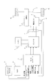
- FIG. 1 is a block diagram showing a main configuration of an electric vehicle provided with a control device for an electric vehicle according to an embodiment.
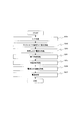
- FIG. 2 is a flow of processing of motor current control performed by a motor controller included in the control device of the electric vehicle of one embodiment.
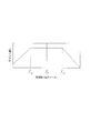
- FIG. 3 is a diagram showing an example of an accelerator opening degree-torque table.
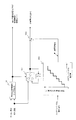
- FIG. 4 is a block diagram for realizing the target stop position calculation process.
- FIG. 5 is a diagram modeling a driving force transmission system of a vehicle.
- FIG. 6 is a block diagram for realizing the stop control process.
- FIG. 7 is a diagram for explaining a method of calculating the motor angular velocity F / B torque.
- FIG. 8 is a diagram for explaining a method of calculating the disturbance torque estimated value.
- FIG. 1 is a block diagram showing a main configuration of an electric vehicle provided with a control device for an electric vehicle according to an embodiment.
- FIG. 2 is a flow of processing of motor current control performed by a motor
- FIG. 9 is a block diagram for realizing a vibration damping control process that suppresses vibration of the driving force transmission system.
- FIG. 10 is a diagram showing an example of transmission characteristics used in the vibration damping control process.
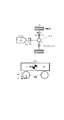
- FIG. 11 is a time chart showing an example of a control result by the control device of the electric vehicle and an example of the control result by the conventional control in the present embodiment.
- FIG. 12 is a time chart showing another example of the control result by the control device of the electric vehicle in the present embodiment.
- FIG. 1 is a block diagram showing an example of a main configuration of an electric vehicle provided with a control device for an electric vehicle according to the first embodiment.
- the control device for an electric vehicle in the present embodiment includes an electric motor 4 (hereinafter, simply referred to as a motor 4) as a part or all of a drive source of the vehicle, and can be applied to an electric vehicle that can travel by the driving force of the motor 4. is there.
- Electric vehicles include not only electric vehicles but also hybrid vehicles and fuel cell vehicles.
- the electric vehicle control device illustrated in FIG. 1 controls acceleration / deceleration and stop of the vehicle only by operating the accelerator pedal.
- the driver of this electric vehicle depresses the accelerator pedal when accelerating, reduces the depressing amount of the accelerator pedal when decelerating or stopping, or operates the depressing amount of the accelerator pedal to zero.
- the vehicle On an uphill road, the vehicle may approach a stopped state while depressing the accelerator pedal in order to prevent the vehicle from moving backward.
- the motor controller 2 transmits signals indicating the vehicle state such as vehicle speed V, accelerator opening degree ⁇ , rotor phase ⁇ of the motor 4, currents iu, iv, and iwa of the motor 4, and relative distance and steering paddle operation signals described later. Input as a digital signal. Then, the motor controller 2 generates a PWM signal for controlling the electric power supplied to the motor 4 based on the input signal, supplies the generated PWM signal to the inverter 3, and opens / closes the switching element of the inverter 3. Control.
- the inverter 3 converts the direct current supplied from the battery 1 into alternating current by turning on / off two switching elements (for example, power semiconductor elements such as IGBTs and MOS-FETs) for each phase. Then, a desired current is passed through the motor 4.
- switching elements for example, power semiconductor elements such as IGBTs and MOS-FETs
- the motor 4 is realized by, for example, a three-phase AC motor.
- the motor 4 generates a driving force by using the alternating current output from the inverter 3, and transmits the driving force to the left and right drive wheels 9a and 9b via the speed reducer 5 and the drive shaft 8. Further, when the motor 4 is rotated by the drive wheels 9a and 9b while the electric vehicle is traveling, the motor 4 recovers the kinetic energy of the electric vehicle as electric energy by generating a regenerative driving force.
- the inverter 3 converts the alternating current generated during the regenerative operation of the motor 4 into a direct current and supplies it to the battery 1.
- the rotation sensor 6 is realized by, for example, a resolver or an encoder, and detects the rotor phase ⁇ of the motor 4.
- the current sensor 7 detects the three-phase alternating currents iu, iv and iwa supplied to the motor 4. However, since the sum of the three-phase alternating currents iu, iv, and iwa is 0 (zero), the current of any two phases may be detected and the current of the remaining one phase may be obtained by calculation.
- the camera 10 is configured to be able to image the traveling direction of the vehicle, and measures the relative distance between the vehicle or obstacle existing in the traveling direction and the own vehicle.
- the camera 10 is an example, and the present invention is not limited to this.
- a sensor or radar capable of measuring the relative distance between the own vehicle and a vehicle or an obstacle existing in the traveling direction may be used.
- the camera 10 may be a stereo camera.
- the direction of travel includes not only the front of the vehicle but also the rear when the vehicle is moving backward. Therefore, in order to capture the direction of travel when the vehicle moves backward, it is preferable to provide a camera capable of capturing not only the front of the vehicle but also the rear of the vehicle.
- the traveling direction of the vehicle is expressed as forward for convenience.
- a vehicle existing in the traveling direction of the vehicle is hereinafter referred to as a front vehicle.
- the steering paddle SW11 detects the operation of the steering paddle by the driver.
- FIG. 2 is a flowchart showing the flow of processing of motor current control performed by the motor controller 2.
- step S201 the motor controller 2 inputs a signal indicating the operating state of the electric vehicle.
- the operating states referred to here are the DC voltage value Vdc (V) between the battery 1 and the inverter 3, the vehicle speed V (km / h) of the electric vehicle, the accelerator opening AP (%), and the rotor phase of the motor 4. These include ⁇ (rad), the rotational speed Nm (rpm) of the motor 4, the three-phase direct current values iu, iv and iwa supplied to the motor 4, and the steering paddle operation signal. Further, the motor controller 2 inputs the relative distance required for the control calculation related to the target stop position calculation process described later.
- the vehicle speed V (km / h) is acquired from a vehicle speed sensor (not shown) or by communication from another controller.
- the motor controller 2 multiplies the rotor mechanical angular velocity ⁇ m by the tire driving radius R and divides it by the gear ratio of the final gear to obtain the vehicle speed v (m / s), and the vehicle speed v (m / s) is 3600 /. By multiplying by 1000, the unit is converted to obtain the vehicle speed V (km / h).
- the accelerator opening AP (%) is acquired from an accelerator opening sensor (not shown) or by communication from another controller such as a vehicle controller (not shown).
- the rotor phase ⁇ (rad) of the motor 4 is acquired from the rotation sensor 6.
- the rotation speed Nm (rpm) of the motor 4 is obtained by multiplying the motor rotation speed ⁇ m (rad / s), which is the mechanical angular velocity of the motor 4, by 60 / (2 ⁇ ).
- the motor rotation speed ⁇ m (rad / s) is obtained by dividing the rotor angular velocity ⁇ (electrical angle) by the number of pole pairs p of the motor 4.
- the rotor angular velocity ⁇ is obtained by differentiating the rotor phase ⁇ .
- the currents iu, iv, and iwa (A) flowing through the motor 4 are acquired from the current sensor 7.
- the DC voltage value Vdc (V) is a power supply voltage value acquired from a voltage sensor (not shown) provided in the DC power supply line between the battery 1 and the inverter 3 or transmitted by the battery controller (not shown). Required from.
- the measured value measured by the camera 10 is acquired. Alternatively, it may be acquired by communication from a vehicle controller (not shown) or another controller.
- the relative distance may be measured using GPS, radar, a distance sensor, vehicle-to-vehicle communication with the vehicle in front, road-to-vehicle communication, or the like.
- the steering paddle operation signal may be acquired by acquiring the steering paddle SW signal, or by communicating with a vehicle controller or another controller (not shown).
- step S202 the motor controller 2 sets the first torque target value Tm1 * .
- the motor controller 2 refers to, for example, the accelerator opening-torque table based on the accelerator opening AP and the motor rotation speed ⁇ m input in step S201, so that the first torque target value Tm1 * To set.
- the motor torque is set so that the amount of motor regeneration is large when the accelerator opening is 0 (fully closed). That is, when the motor rotation speed shows a positive value and at least when the accelerator opening degree is 0 (fully closed), a negative motor torque is set so that a regenerative braking force acts on the electric vehicle.
- the accelerator opening-torque table is not limited to the one shown in FIG.
- step S203 the motor controller 2 executes the target stop position calculation process.
- the target stop position is set based on the relative distance to the vehicle in front or the obstacle acquired from the camera 10 in step S201 and the steering paddle operation signal. Further, it is determined whether or not to intervene the stop position control based on the relative distance between the accelerator opening ⁇ and the vehicle in front, and when the stop position control is intervened, the stop position control start flag is set to 1. The details of the target stop position calculation process will be described later.
- step S204 the motor controller 2 executes the stop control process.
- the torque target value is set according to the stop position control start flag set in step S203.
- the motor controller 2 sets the first torque target value Tm1 * calculated in step S202 to the third torque target value Tm3 * , and when the stop position start flag is 1, the motor controller 2 sets the first torque target value Tm1 *.
- the second torque target value Tm2 * that converges to the disturbance torque estimation value Td determined by the disturbance torque estimation means as the motor rotation speed decreases is set to the third torque target value Tm3 *.
- the second torque target value Tm2 * is positive torque on an uphill road, negative torque on a downhill road, and almost zero on a flat road. As a result, the stopped state can be maintained regardless of the slope of the road surface. The details of the stop control process will be described later.
- step S205 the motor controller 2 performs vibration damping control processing that suppresses driving force transmission system vibration such as torsional vibration of the drive shaft 8 without wasting the drive shaft torque.
- the motor controller 2 inputs the third torque target value Tm3 * calculated in step S204 and the motor rotation speed ⁇ m, and the torque transmission system vibration (drive) without sacrificing the response of the drive shaft torque.
- the sixth torque target value Tm6 * that suppresses the torsional vibration of the shaft 8 is calculated. The details of the vibration damping control process will be described later.
- step S206 the motor controller 2 has a d-axis current target value id * and a q-axis current target value based on the sixth torque target value Tm6 * calculated in step S205, the motor rotation speed ⁇ m, and the DC voltage value Vdc.
- Find iq * a table is prepared in advance for obtaining the relationship between the motor torque command value, the motor rotation speed, and the DC voltage value, and the d-axis current target value and the q-axis current target value through experimental results and simulation results.
- the motor controller 2 When the motor controller 2 acquires the motor torque command value Tm * , the motor rotation speed ⁇ m, and the DC voltage value Vdc, the motor controller 2 obtains the d-axis current target value id * and the q-axis current target value iq * with reference to the prepared table. ..
- step S207 the motor controller 2 performs current control so that the d-axis current id and the q-axis current iq match the d-axis current target value id * and the q-axis current target value iq *, respectively.
- the motor controller 2 calculates the d-axis current id and the q-axis current iq based on the three-phase AC current values iu, iv and iwa input in step S201 and the rotor phase ⁇ of the motor 4. Ask. Subsequently, the motor controller 2 calculates the d-axis and q-axis voltage command values vd and vq from the deviations between the d-axis and q-axis current target values id * and iq * and the d-axis and q-axis currents id and iq. ..
- the motor controller 2 is PWMed from the d-axis and q-axis voltage command values vd and vq, the rotor phase ⁇ of the motor 4, the three-phase AC voltage command values vu, vv and vw, and the DC voltage value Vdc.
- the signals tu (%), tv (%) and tw (%) are obtained. Since the switching element of the inverter 3 is turned ON / OFF according to the PWM signals tu, tv and tw obtained in this way, the motor 4 can be driven with a desired torque indicated by the motor torque command value Tm *.
- step S203 of FIG. 2 The details of the target stop position calculation process performed in step S203 of FIG. 2 will be described below.
- FIG. 4 is a block diagram showing an example of a functional configuration that realizes the target stop position calculation process.
- the target stop position calculation process of the present embodiment includes a stop position control start flag setting device 1001, a relative distance holder 1002, an inter-vehicle distance calculator 1003, and a subtractor 1004.
- the stop position control start flag setter 1001 executes a stop position control start flag process that sets a stop position control start flag according to the accelerator opening degree and the relative distance.
- the flag setting device 1001 sets the stop position control start flag to 1 when the accelerator opening (operation amount) is zero (fully closed) and the relative distance is within a predetermined value. Further, the flag setting device 1001 sets the stop position control start flag to 0 when the accelerator opening degree is other than zero and the relative distance becomes equal to or more than a predetermined value.
- the predetermined value here is a relative distance at which it can be determined that the stop position of the own vehicle is not too close to the vehicle in front or an obstacle even when the conventional stop control in which the target stop position is not set is executed. For example, an experiment. A value found in advance is set as appropriate.
- the relative distance holder 1002 holds the relative distance at the timing when the stop position control start flag set by the flag setter 1001 changes from 0 to 1.
- the retained relative distance is output to the subtractor 1004.
- the inter-vehicle distance calculator 1003 changes the distance constant with the vehicle in front or an obstacle according to the amount of steering paddle operation by the driver, and executes an inter-vehicle distance calculation process for calculating a relative distance target value when the vehicle is stopped.
- the distance constant is a constant for calculating a target value of the relative distance (inter-vehicle distance) between the own vehicle and the vehicle in front or an obstacle when the vehicle is stopped.
- the target value of the inter-vehicle distance when the vehicle is stopped can be arbitrarily changed by changing the distance constant by operating the steering paddle by the driver.
- FIG. 4 shows an example in which the target value of the inter-vehicle distance is set stepwisely larger as the amount of operation of the steering paddle increases.
- the inter-vehicle distance target value calculated by the inter-vehicle distance calculator is subtracted from the relative distance calculated by the relative distance retainer 1002 to calculate the target stop position.
- the calculated target stop position is output to the motor angular velocity feedback torque setter 501 as a target stop position when the vehicle is stopped by the stop control.
- FIG. 5 is a diagram modeling the driving force transmission system of the vehicle, and each parameter in the diagram is as shown below.
- each parameter in the equation (6) is represented by the following equation (7).
- the transmission characteristic Gp (s) can be approximated to the transmission characteristic as shown in the following equation (8), and one pole. And one zero show very close values. This means that ⁇ and ⁇ in the transfer characteristic Gp (s) of the formula (8) show extremely close values.
- the vehicle model Gp (s) of the equation (9) can be regarded as the transmission characteristic Gr (s) shown in the following equation (10).
- the transmission characteristic GpF (s) is obtained based on the above equations (1) to (5), the transmission characteristic GpF (s) is expressed by the following equation (14).
- FIG. 6 is a block diagram showing an example of a functional configuration that realizes stop control processing.
- FIG. 6 shows a motor angular velocity F / B torque setter 501, a disturbance torque estimator 502, a subtractor 503, and a torque comparator 504 as functional configurations for realizing the stop control process.
- the motor angular velocity F / B torque setter 501 has the detected motor rotation velocity ⁇ m, the target stop position calculated by the target stop position calculation process described later, and the stop position set by the stop position control start flag process. Based on the control start flag, the motor angular velocity feedback torque T ⁇ (hereinafter referred to as motor angular velocity F / B torque T ⁇ ) for stopping the electric vehicle by using the regenerative braking force of the motor 4 is calculated. Details will be described with reference to FIG.
- FIG. 7 is a diagram for explaining a method in which the motor angular velocity F / B torque setter 501 calculates the motor angular velocity F / B torque T ⁇ .
- the motor angular velocity F / B torque setter 501 controls the unit converter 601, the integrator 602, the subtractors 603 and 607, the multipliers 604 and 609, the upper and lower limit limits 605, and the rotation speed switcher 606. It includes a block 608.
- the unit converter 601 performs unit conversion (rad / s ⁇ m / s) by multiplying the motor rotation speed ⁇ m by the gain k2.
- the integrator 602 calculates the moving distance after the start of stop control by performing the integral processing on the motor rotation speed ⁇ m that has been unit-converted by the unit converter 601.
- the integrator 602 is initialized at the timing when the stop position control start flag changes from 0 to 1.
- the subtractor 603 calculates the deviation between the target stop position and the moving distance after the start of stop control. The calculated deviation is input to the multiplier 604.
- the multiplier 604 calculates the rotation speed according to the deviation by multiplying the input deviation by the gain k1.
- the upper and lower limit limits 605 apply the upper and lower limit limits to the rotation speed calculated by the multiplier 604.
- the motor rotation speed when the stop control start flag changes from 0 to 1 may be set.
- the lower limit limit value may be set to 0 in order to prevent the vehicle from moving backward.
- the rotation speed switcher 606 performs a rotation speed switching process on the rotation speed output from the upper and lower limit limits 605 according to the state of the stop control start flag, and calculates the first motor rotation speed target value.
- the stop control start flag is 1
- the rotation speed output from the upper and lower limit limits 605 is set to the first motor rotation speed target value.
- the stop control start flag is 0, the first motor rotation speed target value is set to 0.
- the subtractor 607 calculates the deviation between the first motor rotation speed target value and the motor rotation speed ⁇ m, and calculates the second motor rotation speed target value.
- the calculated second motor rotation speed target value is input to the control block 608.
- the + and-positions shown in the vicinity of the subtractor 607 in the figure may be interchanged and may be appropriately set.
- the control block 608 functions as a filter that simulates or approximates the transmission characteristic G ⁇ v (s) of the above equation (13), that is, a filter having the transmission characteristic G ⁇ v (s). Therefore, the control block 608 calculates the estimated vehicle body speed V ⁇ indicating the estimated value of the vehicle body speed V by inputting the motor rotation speed ⁇ m and performing the filtering process in consideration of the transmission characteristic G ⁇ v (s).
- control block 608 may perform filtering processing using the transmission characteristic G ⁇ v'(s) of the equation (15) instead of the transmission characteristic G ⁇ v (s) of the equation (13).
- the arithmetic processing can be reduced as compared with the case where the transmission characteristic G ⁇ v (s) of the equation (13) is used.
- the pole ⁇ p specified by the equation (14) may be used instead of the time constant ⁇ v in the above equation (15).
- the estimated vehicle speed V ⁇ can be calculated by using one pole of the denominator of the transmission characteristic from the motor rotation speed ⁇ m to the vehicle body speed V.
- Equation (16) which is a characteristic that approximates the pole ⁇ far from the origin on the complex plane, may be used.
- control block 608 considers the above equation (16) representing the transmission characteristics from the motor rotation speed ⁇ m to the estimated vehicle body speed V ⁇ and the driving force F to the motor torque Tm, and the transmission characteristic G ⁇ V of the following equation (17). It may be configured to perform the filtering process according to (s).
- the angular velocity feedback torque T ⁇ is calculated by multiplying the estimated vehicle body velocity V ⁇ output from the control block 608 by the gain kvref.
- the gain kvref is set to a value larger than 0 (kvref> 0).
- the disturbance torque estimator 502 calculates the disturbance torque estimation value Td based on the motor rotation speed ⁇ m and the motor torque command value Tm *. Details will be described with reference to FIG.
- FIG. 8 is a diagram for explaining a method of calculating the disturbance torque estimated value Td based on the motor rotation speed ⁇ m and the motor torque command value Tm *.
- the disturbance torque estimator 502 includes a control block 701, a control block 702, and a subtractor 703.
- the control block 701 functions as a filter having a transmission characteristic of H1 (s) / Gr (s), and by inputting the motor rotation speed ⁇ m and performing the filtering process, the first motor torque estimated value is obtained. Is calculated.
- Gr (s) constituting the denominator is the transmission characteristic shown in the above equation (10), and the vehicle model Gp (s) of the equation (9) and the vibration damping control algorithm. It is a vehicle model derived from.
- H1 (s) constituting the numerator of the transfer characteristic is a low-pass filter having a transmission characteristic in which the difference between the denominator order and the numerator order is equal to or greater than the difference between the denominator order and the numerator order of the vehicle model Gp (s). ..
- the control block 702 functions as a filter having a transmission characteristic H1 (s), and by inputting a motor torque command value Tm * and performing a filtering process in consideration of the transmission characteristic H1 (s), the first Calculate the estimated motor torque of 2.
- the subtractor 703 outputs the deviation between the first motor torque estimated value and the second motor torque estimated value as the disturbance torque estimated value Td.
- the subtractor 703 of the present embodiment calculates the disturbance torque estimated value Td by subtracting the first motor torque estimated value from the second motor torque estimated value.
- the disturbance torque estimated value Td in the present embodiment is estimated by the disturbance observer shown in FIG. 8, but may be estimated by using a measuring instrument such as a vehicle front-rear G sensor.
- the disturbance acting on the vehicle air resistance, modeling error due to fluctuation of the vehicle weight due to the number of occupants and the load capacity, rolling resistance of the tire, gradient resistance of the road surface, etc. can be considered, but the vehicle is about to stop or the initials.
- the dominant disturbance factor at the start is gradient resistance.
- disturbance factor varies according to the operating condition, the disturbance torque estimator 502, a motor torque command value Tm *, the motor rotation speed .omega.m, transfer characteristic derived from the damping control algorithms and the vehicle model Gp (s) G r ( Since the disturbance torque estimated value T d is calculated based on s), the above-mentioned disturbance factors can be estimated collectively. As a result, it is possible to realize a smooth stop from deceleration under any driving conditions.
- the subtractor 503 adds the motor angular velocity F / B torque T ⁇ from the motor angular velocity F / B torque setter 501 and the disturbance torque estimated value Td from the disturbance torque estimator 502 to obtain a second torque target value. Calculate Tm2 *.
- Torque comparator 504 compares the first torque target value Tm1 * and the second torque target value Tm2 * of the size, the second torque target value Tm2 * for the first torque target value Tm1 * When it is judged to be large, or when the state of the stop control start flag calculated by the stop position control start flag setter 1001 is 1, it is judged that the vehicle is about to stop, and the third torque target value Tm3 * is set to the first. Stop control is executed by switching from the torque target value Tm1 * of No. 1 to the second torque target value Tm2 *. Further, the torque comparator 504 determines that the first torque target value Tm1 * is larger than the second torque target value Tm2 * , or the stop position calculated by the stop position control start flag processor 1001.
- the third torque target value Tm3 * is switched from the second torque target value Tm2 * to the first torque target value Tm1 * .
- the second torque target value Tm2 * converges to positive torque on an uphill road, negative torque on a downhill road, and approximately zero on a flat road.
- FIG. 9 is a block diagram showing an example of a functional configuration that realizes a vibration damping control process that suppresses vibration of the driving force transmission system of an electric vehicle.
- the vibration damping control process is composed of a combination of an F / F compensator and an F / B compensator.
- FIG. 9 shows the control block 801 as the F / F compensator, and the adder 805, the control block 802, the subtractor 806, the control block 803, and the multiplier 804 as the F / B compensator. It is shown.
- the control block 801 functions as a filter having a transmission characteristic of Gr (s) / Gp (s), and inputs a third torque target value Tm3 * to reduce torsional vibration of the electric vehicle. By performing the process, the fourth torque target value Tm4 * is calculated.
- Gp (s) constituting the denominator is the vehicle model Gp (s) of the formula (9)
- Gr (s) constituting the numerator is the vehicle model Gp (s) and It is a vehicle model of the equation (10) derived from the vibration damping control algorithm.
- the adder 805 adds the output of the multiplier 804 constituting the F / B compensator to the fourth torque target value Tm4 * obtained by feedforward control, and outputs the sixth torque target value Tm6 * . ..
- the control block 802 functions as a filter having a vehicle model Gp (s). Therefore, the control block 802 inputs a sixth torque target value Tm6 * and performs a filtering process in consideration of the vehicle model Gp (s), thereby indicating a motor rotation speed estimated value indicating an estimated value of the motor rotation speed ⁇ m. Calculate ⁇ m ⁇ .
- the subtractor 806 outputs the deviation between the motor rotation speed estimated value ⁇ m ⁇ and the motor rotation speed ⁇ m.
- the subtractor 806 of the present embodiment calculates the deviation by subtracting the motor rotation speed ⁇ m from the motor rotation speed estimated value ⁇ m ⁇ .
- the control block 803 functions as a filter having a transmission characteristic of H2 (s) / Gp (s), and the estimated value of the disturbance d is obtained by inputting the deviation of the subtractor 806 and performing the filtering process.
- the estimated disturbance d ⁇ shown is calculated.
- the vehicle model Gp (s) of the equation (9) and the vehicle model derived from the vibration damping control algorithm, and H2 (s) constituting the numerator is feedback that reduces only vibration. It is a bandpass filter having an elemental transmission characteristic.
- the multiplier 804 multiplies the estimated disturbance d ⁇ from the control block 803 by the feedback gain K FB to calculate a fifth torque target value Tm5 * in consideration of the control error of the motor rotation speed ⁇ m. And the adder 805 by a fifth torque target value Tm5 * is added to the fourth torque target value Tm4 *, so as to suppress the generation of torsional vibration of the electric vehicle sixth torque target value of Tm6 * to The motor rotation speed ⁇ m is fed back.
- FIG. 10 is a diagram showing an example of a bandpass filter for realizing the transmission characteristic H2 (s).
- the damping characteristic on the low-pass side and the damping characteristic on the high-pass side are substantially the same, and the torsional resonance frequency of the drive system is near the center of the pass band on the logarithmic axis (log scale). Is set to be. By setting the characteristics of the filter in this way, the greatest effect can be obtained.
- the transmission characteristic H2 (s) is configured by using a first-order high-pass filter and a first-order low-pass filter
- the transmission characteristic H2 (s) is represented by the following equation (18), and the frequency fp is the torsion of the drive system.
- the resonance frequency is set, and k is set to an arbitrary value.
- ⁇ L 1 / (2 ⁇ f HC)
- f HC k ⁇ f p
- ⁇ H 1 / (2 ⁇ f LC)
- f LC f p / k.
- step S205 since torsional vibration is generated in the driving force transmission system of the electric vehicle, stop control and vibration damping control are used together. However, in the case of an electric vehicle in which torsional vibration is not generated in the driving force transmission system, the control in step S205 is performed. It is not necessary to execute the vibration control process.
- FIG. 11A shows a flat road
- FIG. 11B shows an uphill road
- FIG. 11C shows a time chart when stop control is executed on a downhill road.
- the broken line represents the conventional stop control (conventional example)
- the solid line represents the stop control of the present embodiment (example).
- FIG. 12 shows a time chart when the vehicle in front moves during the stop control of the present embodiment and the vehicle shifts to the conventional example.
- both FIGS. 11 and 12 show the motor torque command value, the motor rotation speed, and the position of the own vehicle from the top.
- the driver's accelerator opening operation amount becomes zero at time t0, it is determined that the stop control starts, and the motor rotation speed asymptotically becomes zero by the stop control until time t3. Converges on.
- the regenerative torque is small because the motor torque is uniquely determined regardless of the relative distance to the vehicle in front or obstacles. As a result, it can be seen that at time t2, the relative distance to the vehicle in front and the obstacle becomes 0, and the vehicle collides. As described above, in the conventional example, it is not possible to stop at the target stop position intended by the driver.
- the accelerator opening operation amount of the driver becomes zero at time t0
- the stop control is started by determining that the stop control is started, and the vehicle and the vehicle in front and obstacles reach the time t1. Since the motor regeneration torque can be set large according to the relative distance, it can be seen that at time t3, a smooth stop can be realized while ensuring a relative distance to the vehicle in front or an obstacle.
- the accelerator operation amount of the driver becomes zero at time t0, it is determined that the stop control starts, and the motor rotation speed asymptotically converges to zero by the stop control until time t3. doing.
- the motor regenerative torque is set large at time t1
- the time until the motor stops is shortened. Therefore, the position when the motor rotation speed converges to zero (the stop position of the own vehicle) stops far in front of the position of the vehicle in front or the obstacle, and stops at the target stop position intended by the driver. Can't.
- the accelerator opening operation amount of the driver becomes zero at time t0
- the stop control is determined to be the start of stop control, and the stop control is started. Since the motor regeneration torque can be set small, it can be seen that at time t4, a smooth stop can be realized while ensuring a relative distance to the vehicle in front and obstacles.
- the accelerator operation amount of the driver becomes zero at time t0, it is determined that the stop control starts, and the motor rotation speed asymptotically converges to zero by the stop control until time t2. doing.
- the accelerator opening operation amount of the driver becomes zero at time t0
- the stop control is determined to be the start of stop control, and the stop control is started. Since the motor regeneration torque can be set large, it can be seen that at time t2, a smooth stop can be realized while ensuring a relative distance to the vehicle in front and obstacles.
- the own vehicle can be stopped at the stop position intended by the driver, that is, the target stop position.
- FIG. 12 shows the behavior when the vehicle in front moves during the stop control according to the present embodiment.
- the solid line after time t1 shows the behavior when shifting to the conventional stop control
- the broken line after time t1 shows the behavior when shifting to the conventional stop control.
- the value of the first motor rotation speed target value may be set to zero, more specifically, the stop control.
- the output of the rotation speed switch 606 of the motor angular velocity F / B torque setter 501 described above may be set to zero, the torque of the motor 4 is disturbed as the motor rotation speed decreases without considering the target stop position. It is possible to shift to the conventional stop control that converges to the torque.
- the vehicle in front started moving at time t0. Then, since the distance between the target stop position and the vehicle in front exceeds a predetermined value at time t1, the vehicle shifts to the conventional stop control in which the target stop position is not set. In this way, by shifting to the conventional stop control at the time t1 shift and making the deceleration equivalent to that of the conventional example, the vehicle stops without causing discomfort to the driver with respect to the position of the vehicle in front after the movement. be able to.
- the vehicle can be smoothly stopped at the target stop position according to the relative distance to the vehicle in front or the obstacle.
- the electric vehicle control method of one embodiment is a control method of an electric vehicle that uses a motor as a traveling drive source and decelerates by the regenerative braking force of the motor 4.
- the amount of accelerator operation is acquired, the disturbance torque acting on the vehicle body of the electric vehicle is estimated, and the angular speed of the rotating body (motor rotation speed ⁇ m) that correlates with the rotation speed of the drive shaft 8 that drives the electric vehicle.
- the first torque command value (first torque target value Tm1 * ) is calculated based on the accelerator operation amount, and the first torque command value is set to the torque command value (motor torque command value Tm * ).
- the torque generated in the motor 4 is controlled based on the torque command value, the target stop position when the electric vehicle stops is set, and the target angular speed of the rotating body (the first) according to the distance from the electric vehicle to the target stop position.
- a second torque command value (second torque target value Tm2) for stopping the electric vehicle at the target stop position based on the difference between the target angular speed and the acquired angular speed after calculating the motor rotation speed target value of 1). * ) Is calculated.
- the accelerator operation amount decreases or becomes zero and the electric vehicle is about to stop
- the second torque command value is set to the torque command value, and the motor is set according to the distance to the target stop position.
- the torque command value is converged to the disturbance torque estimated value Td.
- the target angular velocity can be calculated according to the distance to the target stop position, and the motor torque can be controlled according to the target angular velocity, so that the own vehicle can be stopped at the desired position of the driver. ..
- the target stop position is calculated by subtracting a predetermined distance from the relative distance between the electric vehicle and the vehicle or obstacle existing in the traveling direction of the electric vehicle.
- the target stop position is set according to the distance between the vehicle and the vehicle in front. Therefore, even if the deceleration of the vehicle in front increases, the possibility of colliding with the vehicle in front when the vehicle is stopped can be reduced. Can be done. Further, by being controlled in this way, the need for the driver to step on the brake pedal is reduced, so that the drivability is improved and the commercial value of the vehicle can be increased. Further, since the target stop position is calculated by subtracting a predetermined distance from the relative distance to the vehicle or obstacle, it is possible to stop at a certain distance with respect to the vehicle in front or the obstacle.
- the above-mentioned predetermined distance is a relative distance between the electric vehicle when the electric vehicle is stopped and a vehicle or an obstacle existing in the traveling direction of the electric vehicle. This is the target value of, and is set to be changeable by the driver. This allows the driver to arbitrarily change the distance from the own vehicle to the vehicle in front or an obstacle when the vehicle is stopped.
- the relative distance between the electric vehicle and the vehicle or an obstacle existing in the traveling direction of the electric vehicle is determined by a sensor, a radar, or a camera 10 capable of measuring the distance. Is detected using. As a result, the relative distance to the own vehicle can be detected, and the target stop position can be calculated based on the detected relative distance.
- the vehicle when the relative distance between the electric vehicle and the vehicle or an obstacle existing in the traveling direction of the electric vehicle is reduced to a predetermined value or less, the vehicle is about to stop. Judging, the torque command value (motor torque command value Tm * ) is changed from the first torque command value (first torque target value Tm1 * ) to the second torque command value (second torque target value Tm2 * ). Switch. As a result, after decelerating by the first torque target value Tm1 * , the motor torque command value Tm * switched to the second torque target value Tm2 * for stopping the vehicle at the target stop position is converged to the disturbance torque. Therefore, smooth deceleration without acceleration and vibration can be realized at all times, and the vehicle can be stopped at the target stop position.
- the magnitudes of the first torque command value and the second torque command value are compared, and the first torque command value is compared with the second torque command value.
- the torque command value (motor torque command value Tm * ) is changed from the second torque command value (second torque target value Tm2 * ) to the first torque command value (first torque target value Tm1 *).
- the second torque target value Tm2 * that stops the vehicle at the target stop position is switched to the first torque target value Tm1 * that is calculated according to the accelerator operation amount, so that the vehicle can run according to the driver's request. become.
- the accelerator operation amount when the accelerator operation amount is reduced or becomes zero and the electric vehicle is about to stop, a vehicle or an obstacle existing in the traveling direction of the electric vehicle moves. If the target stop position and the position of the vehicle or obstacle are separated by a predetermined distance or more, the target angular velocity is set to zero.
- the stop control of the present embodiment for stopping at the target stop position can be shifted to the conventional stop control in which the torque of the motor 4 is converged to the disturbance torque as the motor rotation speed decreases without considering the target stop position. it can.
- the target stop position set before the vehicle in front moves is maintained, so that it is possible to avoid a situation in which the vehicle is stopped too far from the vehicle in front, which makes the driver feel uncomfortable. The vehicle can be stopped without causing it.
- a predetermined limit value is applied to the target angular velocity (output value of the multiplier 604). As a result, it is possible to prevent the motor torque command value Tm * from suddenly fluctuating at the start of stop control.
- the motor rotation speed ⁇ m used in the above-mentioned various calculations may be any angular velocity of the rotating body that correlates with the rotation speed of the drive shaft 8 that drives the electric vehicle, and may be changed as appropriate.
- the wheel speed, the vehicle body speed, the rotation speed of the drive shaft, or the like may be used instead of the motor rotation speed ⁇ m.
Landscapes
- Engineering & Computer Science (AREA)
- Power Engineering (AREA)
- Transportation (AREA)
- Mechanical Engineering (AREA)
- Electric Propulsion And Braking For Vehicles (AREA)
- Control Of Driving Devices And Active Controlling Of Vehicle (AREA)
Abstract
Description
図1は、第1の実施形態における電動車両の制御装置を備えた電気自動車の主要構成の一例を示すブロック図である。
Jw :駆動輪のイナーシャ
M :車両の質量
Kd :駆動系の捻り剛性
Kt :タイヤと路面の摩擦に関する係数
N :オーバーオールギヤ比
r :タイヤの過重半径
ωm :モータ回転速度
Tm * :モータトルク指令値
Td :駆動輪のトルク
F :車両に加えられる力(駆動力)
V :車両の速度(車体速度)
ωw :駆動輪の角速度


続いて、モータトルクTmから電動車両の駆動力Fまでの伝達特性GpF(s)について説明する。


Claims (9)
- モータを走行駆動源とし、前記モータの回生制動力により減速する電動車両の制御方法であって、
アクセル操作量を取得し、
前記電動車両の車体に作用する外乱トルクを推定し、
前記電動車両を駆動する駆動軸の回転速度に相関のある回転体の角速度を取得し、
前記アクセル操作量に基づいて第1のトルク指令値を算出し、
前記第1のトルク指令値をトルク指令値に設定し、
前記トルク指令値に基づいて前記モータに生じるトルクを制御し、
前記電動車両が停止する際の目標停止位置を設定し、
前記電動車両から前記目標停止位置までの距離に応じて、前記回転体の目標角速度を算出し、
前記目標角速度と取得した前記角速度との差分に基づいて、前記電動車両を前記目標停止位置に停止させるための第2のトルク指令値を算出し、
前記アクセル操作量が減少またはゼロになり、かつ、前記電動車両が停車間際である場合には、前記第2のトルク指令値を前記トルク指令値に設定するとともに、前記目標停止位置までの距離に応じて前記モータの制駆動力を調整して、前記トルク指令値を前記外乱トルクに収束させる、
電動車両の制御方法。 - 請求項1に記載の電動車両の制御方法において、
前記目標停止位置は、前記電動車両と、当該電動車両の進行方向に存在する車両又は障害物との相対距離から所定の距離を減じて算出される、
電動車両の制御方法。 - 請求項2に記載の電動車両の制御方法において、
前記所定の距離は、前記電動車両の停止時における当該電動車両と、当該電動車両の進行方向に存在する車両又は障害物との相対距離の目標値であって、ドライバによって変更可能に設定される、
電動車両の制御方法。 - 請求項2または3に記載の電動車両の制御方法において、
前記電動車両と、当該電動車両の進行方向に存在する車両又は障害物との相対距離は、距離を測定可能なセンサ、レーダ、又はカメラを用いて検出する、
電動車両の制御方法。 - 請求項1から4のいずれか一項に記載の電動車両の制御方法において、
前記電動車両と、当該電動車両の進行方向に存在する車両又は障害物との相対距離が所定値以下に低下した場合には、前記停車間際と判断して、前記トルク指令値を前記第1のトルク指令値から前記第2のトルク指令値に切替える、
電動車両の制御方法。 - 請求項5に記載の電動車両の制御方法において、
前記第1のトルク指令値と前記第2のトルク指令値の大きさを比較し、
前記第2のトルク指令値に対して前記第1のトルク指令値が大きい場合には、前記トルク指令値を前記第2のトルク指令値から前記第1のトルク指令値に切替える、
電動車両の制御方法。 - 請求項1から6のいずれか一項に記載の電動車両の制御方法において、
前記アクセル操作量が減少またはゼロになり、かつ、前記電動車両が停車間際である場合に前記電動車両の進行方向に存在する車両又は障害物が移動することにより前記目標停止位置と当該車両又は障害物の位置とが所定距離以上離れた場合には、
前記目標角速度をゼロに設定する、
電動車両の制御方法。 - 請求項1から7のいずれか一項に記載の電動車両の制御方法において、
前記目標角速度には、所定のリミット値が施される、
電動車両の制御方法。 - モータと、前記モータを制御するコントローラとを備える電動車両の制御装置であって、
前記コントローラは、
アクセル操作量を取得し、
前記電動車両の車体に作用する外乱トルクを推定し、
前記電動車両を駆動する駆動軸の回転速度に相関のある回転体の角速度を取得し、
前記アクセル操作量に基づいて第1のトルク指令値を算出し、
前記第1のトルク指令値をトルク指令値に設定し、
前記トルク指令値に基づいて前記モータに生じるトルクを制御し、
前記電動車両が停止する際の目標停止位置を設定し、
前記電動車両から前記目標停止位置までの距離に応じて、前記回転体の目標角速度を算出し、
前記目標角速度と取得した前記角速度との差分に基づいて、前記電動車両を前記目標停止位置に停止させるための第2のトルク指令値を算出し、
前記アクセル操作量が減少またはゼロになり、かつ、前記電動車両が停車間際である場合には、前記第2のトルク指令値を前記トルク指令値に設定するとともに、前記目標停止位置までの距離に応じて前記モータの制駆動力を調整して、前記トルク指令値を前記外乱トルクに収束させる、
電動車両の制御装置。
Priority Applications (5)
| Application Number | Priority Date | Filing Date | Title |
|---|---|---|---|
| US17/771,213 US12240352B2 (en) | 2019-10-28 | 2019-10-28 | Control method for electric vehicle and control device for electric vehicle |
| PCT/JP2019/042132 WO2021084574A1 (ja) | 2019-10-28 | 2019-10-28 | 電動車両の制御方法及び電動車両の制御装置 |
| EP19951005.8A EP4052951A4 (en) | 2019-10-28 | 2019-10-28 | CONTROL DEVICE FOR ELECTRIC MOTOR VEHICLE AND CONTROL METHOD FOR ELECTRIC MOTOR VEHICLE |
| JP2021553897A JP7283565B2 (ja) | 2019-10-28 | 2019-10-28 | 電動車両の制御方法及び電動車両の制御装置 |
| CN201980101521.7A CN114599544B (zh) | 2019-10-28 | 2019-10-28 | 电动车辆的控制方法及电动车辆的控制装置 |
Applications Claiming Priority (1)
| Application Number | Priority Date | Filing Date | Title |
|---|---|---|---|
| PCT/JP2019/042132 WO2021084574A1 (ja) | 2019-10-28 | 2019-10-28 | 電動車両の制御方法及び電動車両の制御装置 |
Publications (1)
| Publication Number | Publication Date |
|---|---|
| WO2021084574A1 true WO2021084574A1 (ja) | 2021-05-06 |
Family
ID=75715843
Family Applications (1)
| Application Number | Title | Priority Date | Filing Date |
|---|---|---|---|
| PCT/JP2019/042132 Ceased WO2021084574A1 (ja) | 2019-10-28 | 2019-10-28 | 電動車両の制御方法及び電動車両の制御装置 |
Country Status (5)
| Country | Link |
|---|---|
| US (1) | US12240352B2 (ja) |
| EP (1) | EP4052951A4 (ja) |
| JP (1) | JP7283565B2 (ja) |
| CN (1) | CN114599544B (ja) |
| WO (1) | WO2021084574A1 (ja) |
Cited By (5)
| Publication number | Priority date | Publication date | Assignee | Title |
|---|---|---|---|---|
| CN113306408A (zh) * | 2021-06-04 | 2021-08-27 | 江西江铃集团晶马汽车有限公司 | 一种新能源客车用全新驾驶操控装置及其工作方法 |
| JP2023088685A (ja) * | 2021-12-15 | 2023-06-27 | 日産自動車株式会社 | 電動車両の制御方法、電動車両の制御装置 |
| JP2023140944A (ja) * | 2022-03-23 | 2023-10-05 | 三菱自動車工業株式会社 | 車両の制御装置 |
| WO2024053566A1 (ja) * | 2022-09-07 | 2024-03-14 | 三菱重工業株式会社 | 情報処理装置、情報処理方法、プログラム |
| CN118872196A (zh) * | 2022-03-18 | 2024-10-29 | 日产自动车株式会社 | 发电机控制方法以及发电机控制装置 |
Families Citing this family (3)
| Publication number | Priority date | Publication date | Assignee | Title |
|---|---|---|---|---|
| KR102882420B1 (ko) * | 2019-12-16 | 2025-11-06 | 현대자동차주식회사 | 전기자동차의 회생제동토크 제어 장치 및 그 방법 |
| US11745600B2 (en) * | 2020-02-04 | 2023-09-05 | Subaru Corporation | Driving force controller for vehicle |
| WO2024069806A1 (ja) * | 2022-09-28 | 2024-04-04 | 株式会社Subaru | 車両用制御装置 |
Citations (6)
| Publication number | Priority date | Publication date | Assignee | Title |
|---|---|---|---|---|
| JP2000177428A (ja) * | 1998-12-21 | 2000-06-27 | Toyota Motor Corp | 車両走行制御方法およびシステム |
| JP2005231588A (ja) * | 2004-02-23 | 2005-09-02 | Nissan Motor Co Ltd | 車両の停車支援装置 |
| JP2015019521A (ja) * | 2013-07-11 | 2015-01-29 | トヨタ自動車株式会社 | 回生発電機付車両 |
| WO2015083213A1 (ja) * | 2013-12-02 | 2015-06-11 | 日産自動車株式会社 | 電動車両の制御装置および電動車両の制御方法 |
| JP2015133799A (ja) | 2014-01-10 | 2015-07-23 | 日産自動車株式会社 | 電動車両の制御装置および電動車両の制御方法 |
| JP2017175853A (ja) * | 2016-03-25 | 2017-09-28 | 日産自動車株式会社 | 電動車両の制御方法、及び、電動車両の制御装置 |
Family Cites Families (13)
| Publication number | Priority date | Publication date | Assignee | Title |
|---|---|---|---|---|
| JP3225578B2 (ja) * | 1992-03-19 | 2001-11-05 | 株式会社日立製作所 | 電気自動車 |
| JP5286921B2 (ja) * | 2008-05-12 | 2013-09-11 | 日産自動車株式会社 | 車両用制振制御装置 |
| JP2011087395A (ja) * | 2009-10-15 | 2011-04-28 | Denso Corp | 車両のモータ制御装置 |
| US9114728B2 (en) * | 2011-10-24 | 2015-08-25 | Kawasaki Jukogyo Kabushiki Kaisha | Electric vehicle |
| JP6201210B2 (ja) * | 2013-09-24 | 2017-09-27 | 日立オートモティブシステムズ株式会社 | 電動車両の制御装置及び電動車両の制御方法 |
| JP6177666B2 (ja) * | 2013-11-12 | 2017-08-09 | 日立オートモティブシステムズ株式会社 | 移動体の駆動制御装置 |
| JP2015116000A (ja) * | 2013-12-10 | 2015-06-22 | カルソニックカンセイ株式会社 | 電動車両の駆動力制御装置 |
| JP6033973B2 (ja) * | 2014-01-22 | 2016-11-30 | カルソニックカンセイ株式会社 | 電動車両の駆動力制御装置 |
| JP6342747B2 (ja) * | 2014-08-22 | 2018-06-13 | 株式会社デンソー | 回転電機の制御装置 |
| WO2016120978A1 (ja) * | 2015-01-26 | 2016-08-04 | 日産自動車株式会社 | 電動車両の制御装置および電動車両の制御方法 |
| WO2016158720A1 (ja) * | 2015-03-27 | 2016-10-06 | カルソニックカンセイ株式会社 | 電動車両の駆動力制御装置 |
| JP6332180B2 (ja) * | 2015-07-15 | 2018-05-30 | トヨタ自動車株式会社 | 車両の制御装置 |
| MY190446A (en) * | 2015-08-26 | 2022-04-21 | Nissan Motor | Control method and control device for electric vehicle |
-
2019
- 2019-10-28 WO PCT/JP2019/042132 patent/WO2021084574A1/ja not_active Ceased
- 2019-10-28 JP JP2021553897A patent/JP7283565B2/ja active Active
- 2019-10-28 US US17/771,213 patent/US12240352B2/en active Active
- 2019-10-28 CN CN201980101521.7A patent/CN114599544B/zh active Active
- 2019-10-28 EP EP19951005.8A patent/EP4052951A4/en active Pending
Patent Citations (6)
| Publication number | Priority date | Publication date | Assignee | Title |
|---|---|---|---|---|
| JP2000177428A (ja) * | 1998-12-21 | 2000-06-27 | Toyota Motor Corp | 車両走行制御方法およびシステム |
| JP2005231588A (ja) * | 2004-02-23 | 2005-09-02 | Nissan Motor Co Ltd | 車両の停車支援装置 |
| JP2015019521A (ja) * | 2013-07-11 | 2015-01-29 | トヨタ自動車株式会社 | 回生発電機付車両 |
| WO2015083213A1 (ja) * | 2013-12-02 | 2015-06-11 | 日産自動車株式会社 | 電動車両の制御装置および電動車両の制御方法 |
| JP2015133799A (ja) | 2014-01-10 | 2015-07-23 | 日産自動車株式会社 | 電動車両の制御装置および電動車両の制御方法 |
| JP2017175853A (ja) * | 2016-03-25 | 2017-09-28 | 日産自動車株式会社 | 電動車両の制御方法、及び、電動車両の制御装置 |
Non-Patent Citations (1)
| Title |
|---|
| See also references of EP4052951A4 |
Cited By (7)
| Publication number | Priority date | Publication date | Assignee | Title |
|---|---|---|---|---|
| CN113306408A (zh) * | 2021-06-04 | 2021-08-27 | 江西江铃集团晶马汽车有限公司 | 一种新能源客车用全新驾驶操控装置及其工作方法 |
| JP2023088685A (ja) * | 2021-12-15 | 2023-06-27 | 日産自動車株式会社 | 電動車両の制御方法、電動車両の制御装置 |
| JP7732348B2 (ja) | 2021-12-15 | 2025-09-02 | 日産自動車株式会社 | 電動車両の制御方法、電動車両の制御装置 |
| CN118872196A (zh) * | 2022-03-18 | 2024-10-29 | 日产自动车株式会社 | 发电机控制方法以及发电机控制装置 |
| JP2023140944A (ja) * | 2022-03-23 | 2023-10-05 | 三菱自動車工業株式会社 | 車両の制御装置 |
| JP7688327B2 (ja) | 2022-03-23 | 2025-06-04 | 三菱自動車工業株式会社 | 車両の制御装置 |
| WO2024053566A1 (ja) * | 2022-09-07 | 2024-03-14 | 三菱重工業株式会社 | 情報処理装置、情報処理方法、プログラム |
Also Published As
| Publication number | Publication date |
|---|---|
| JPWO2021084574A1 (ja) | 2021-05-06 |
| US12240352B2 (en) | 2025-03-04 |
| EP4052951A1 (en) | 2022-09-07 |
| CN114599544B (zh) | 2024-03-08 |
| EP4052951A4 (en) | 2022-11-16 |
| US20220379732A1 (en) | 2022-12-01 |
| JP7283565B2 (ja) | 2023-05-30 |
| CN114599544A (zh) | 2022-06-07 |
Similar Documents
| Publication | Publication Date | Title |
|---|---|---|
| JP7283565B2 (ja) | 電動車両の制御方法及び電動車両の制御装置 | |
| JP6787410B2 (ja) | 電動車両の制御方法、及び、制御装置 | |
| JP6135775B2 (ja) | 電動車両の制御装置および電動車両の制御方法 | |
| JP6741084B2 (ja) | 電動車両の制御方法、および、電動車両の制御装置 | |
| JP6402782B2 (ja) | 電動車両の制御装置および電動車両の制御方法 | |
| JP6760401B2 (ja) | 電動車両の制御方法、及び、制御装置 | |
| JP7056219B2 (ja) | 電動車両の制御方法および電動車両の制御装置 | |
| WO2016120979A1 (ja) | 電動車両の制御装置および電動車両の制御方法 | |
| JP6237789B2 (ja) | 電動車両の制御装置および電動車両の制御方法 | |
| US11801757B2 (en) | Control device for electric vehicle and control method for electric vehicle | |
| WO2016120980A1 (ja) | 車両の制御装置および車両の制御方法 | |
| JP6729002B2 (ja) | 電動車両の制御方法、及び、制御装置 | |
| JP6992298B2 (ja) | 電動車両の制御装置及び電動車両の制御方法 | |
| JP6880674B2 (ja) | 電動車両の制御方法、及び、電動車両の制御装置 | |
| JP7732348B2 (ja) | 電動車両の制御方法、電動車両の制御装置 | |
| WO2015079574A1 (ja) | 電動車両の制御装置および電動車両の制御方法 |
Legal Events
| Date | Code | Title | Description |
|---|---|---|---|
| 121 | Ep: the epo has been informed by wipo that ep was designated in this application |
Ref document number: 19951005 Country of ref document: EP Kind code of ref document: A1 |
|
| ENP | Entry into the national phase |
Ref document number: 2021553897 Country of ref document: JP Kind code of ref document: A |
|
| NENP | Non-entry into the national phase |
Ref country code: DE |
|
| ENP | Entry into the national phase |
Ref document number: 2019951005 Country of ref document: EP Effective date: 20220530 |
|
| WWG | Wipo information: grant in national office |
Ref document number: 17771213 Country of ref document: US |