WO2021084977A1 - 光拡散フィルム - Google Patents
光拡散フィルム Download PDFInfo
- Publication number
- WO2021084977A1 WO2021084977A1 PCT/JP2020/035798 JP2020035798W WO2021084977A1 WO 2021084977 A1 WO2021084977 A1 WO 2021084977A1 JP 2020035798 W JP2020035798 W JP 2020035798W WO 2021084977 A1 WO2021084977 A1 WO 2021084977A1
- Authority
- WO
- WIPO (PCT)
- Prior art keywords
- light diffusing
- film
- resin
- light
- value
- Prior art date
- Legal status (The legal status is an assumption and is not a legal conclusion. Google has not performed a legal analysis and makes no representation as to the accuracy of the status listed.)
- Ceased
Links
Images




Classifications
-
- G—PHYSICS
- G02—OPTICS
- G02B—OPTICAL ELEMENTS, SYSTEMS OR APPARATUS
- G02B5/00—Optical elements other than lenses
- G02B5/02—Diffusing elements; Afocal elements
- G02B5/0205—Diffusing elements; Afocal elements characterised by the diffusing properties
- G02B5/0236—Diffusing elements; Afocal elements characterised by the diffusing properties the diffusion taking place within the volume of the element
- G02B5/0242—Diffusing elements; Afocal elements characterised by the diffusing properties the diffusion taking place within the volume of the element by means of dispersed particles
-
- G—PHYSICS
- G02—OPTICS
- G02B—OPTICAL ELEMENTS, SYSTEMS OR APPARATUS
- G02B5/00—Optical elements other than lenses
- G02B5/02—Diffusing elements; Afocal elements
-
- G—PHYSICS
- G02—OPTICS
- G02B—OPTICAL ELEMENTS, SYSTEMS OR APPARATUS
- G02B5/00—Optical elements other than lenses
- G02B5/02—Diffusing elements; Afocal elements
- G02B5/0205—Diffusing elements; Afocal elements characterised by the diffusing properties
- G02B5/021—Diffusing elements; Afocal elements characterised by the diffusing properties the diffusion taking place at the element's surface, e.g. by means of surface roughening or microprismatic structures
- G02B5/0226—Diffusing elements; Afocal elements characterised by the diffusing properties the diffusion taking place at the element's surface, e.g. by means of surface roughening or microprismatic structures having particles on the surface
-
- F—MECHANICAL ENGINEERING; LIGHTING; HEATING; WEAPONS; BLASTING
- F21—LIGHTING
- F21V—FUNCTIONAL FEATURES OR DETAILS OF LIGHTING DEVICES OR SYSTEMS THEREOF; STRUCTURAL COMBINATIONS OF LIGHTING DEVICES WITH OTHER ARTICLES, NOT OTHERWISE PROVIDED FOR
- F21V3/00—Globes; Bowls; Cover glasses
- F21V3/02—Globes; Bowls; Cover glasses characterised by the shape
-
- G—PHYSICS
- G02—OPTICS
- G02B—OPTICAL ELEMENTS, SYSTEMS OR APPARATUS
- G02B5/00—Optical elements other than lenses
- G02B5/02—Diffusing elements; Afocal elements
- G02B5/0268—Diffusing elements; Afocal elements characterized by the fabrication or manufacturing method
Definitions
- the present invention relates to a light diffusing film.
- a device using a light emitting diode has been known as a light emitting device capable of emitting high energy light with low power consumption. Since the light emitted from the LED has strong directivity, it is required to disperse the light highly.
- a device using a light emitting diode it is used as an LED lighting device for an automobile light, a refrigerator, a microwave oven, an indoor light, or the like. LED lighting devices are required to have a particularly high degree of dispersibility (for example, Patent Document 1).
- a light diffusing film is used for the purpose of diffusing light.
- haze may be used as an index for evaluating the diffusivity of light.
- the half-value angle is used as an index of light diffusivity in the LED lighting device.
- the half-value angle (degree) is an angle that is half the intensity I 1/2 of the intensity I 0 of the front light that passes through the light diffusing film and has an angle of 0 degrees of the light source. That is, in the LED lighting device, a light diffusing film showing a wide half-value angle (degree) is required.
- LED lighting devices have a high degree of freedom in design, and many lighting devices with new shapes have been announced. Among them, parts such as covers of LED lighting devices are also required to have a degree of freedom in shape, and curved surfaces having a high radius of curvature when molded from a flat plate sheet shape and flat surfaces having a high elongation rate during molding are required. May exist. It has been clarified that when a light diffusing film is molded in order to meet the demand, there is a problem that the light diffusing performance of the light diffusing film is lowered in a portion having a high radius of curvature or a portion having a high elongation rate. .. In particular, when the light diffusing film is stretched, the half-value angle tends to decrease even if the decrease in haze is slight.
- an object of the present invention is to provide a light diffusing film capable of suppressing a decrease in half-value angle even after processing with a high elongation rate.
- the present inventors use a light diffusing film provided with a light diffusing layer containing light diffusing particles and a resin binder, and the ratio of the average film thickness T of the light diffusing layer to the average particle diameter t of the light diffusing particles (T). It has been found that when / t) is 3.0 or more, a light diffusing film capable of suppressing a decrease in half-value angle can be obtained even after processing with a high elongation rate. That is, the present invention relates to the following [1] to [5].
- a light diffusing film comprising a base film and a light diffusing layer containing light diffusing particles and a resin binder.
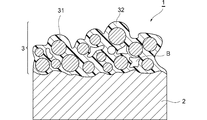
- FIG. 1 is a schematic cross-sectional view of the light diffusing film 1 of the present embodiment.
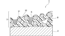
- FIG. 2 is a schematic cross-sectional view of the light diffusing film 1 of the present embodiment when stretched.
- FIG. 3 is a schematic cross-sectional view of the light diffusing film 1 of the present embodiment when further stretched.
- FIG. 4 is a schematic cut-off view showing the action when the conventional light diffusion film C1 is stretched.
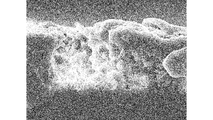
- FIG. 5 is an SEM photograph of a cross section of the light diffusing film at an elongation rate of 0%.
- FIG. 6 is an SEM photograph of a cross section of the light diffusing film at an elongation rate of 40%.
- FIG. 7 is an SEM photograph of a cross section of the light diffusing film at an elongation rate of 80%.
- the light diffusing film according to the present embodiment includes a base film and a light diffusing layer containing light diffusing particles and a resin binder.
- the ratio (T / t) of the average film thickness T of the light diffusing layer to the average particle diameter t of the light diffusing particles (hereinafter, also simply referred to as “T / t ratio”) is 3.0. That is all. According to the light diffusing film according to the present embodiment, it is possible to suppress a decrease in the half-value angle even after processing with a high elongation rate.
- FIG. 1 is a schematic cross-sectional view of the light diffusion film 1 of the present embodiment.
- the light diffusing film 1 of the present embodiment includes a base film 2 and a light diffusing layer 3 provided on one surface 2a side of the base film 2.
- the light diffusing layer 3 is exposed on the outermost surface. Since the light diffusing layer 3 is exposed on the outermost surface in this way, by stretching the light diffusing film 1, unevenness is easily formed on the surface of the light diffusing layer 3, and the half-value angle after stretching is maintained. It will be easier to do.
- the light diffusing layer 3 contains the light diffusing particles 31 and the resin 32.
- the light diffusion layer 3 has a void B inside.
- the light diffusing layer 3 has a T / t ratio of a predetermined range or more, so that the light diffusing particles 31 are formed so as to be stacked in the thickness direction of the light diffusing layer 3.
- the light diffusing film 1 of the present embodiment is used after being molded under heating conditions according to, for example, the curved surface shape of the surface of a transparent component. During the molding process, the light diffusing film 1 is elongated according to the shape of the curved surface.
- the light diffusing film 1 according to the present embodiment can maintain the half-value angle due to the light diffusion of the light diffusing film even by the stretching.
- the light diffusing film 1 when not stretched, the light diffusing film 1 is diffused by the light diffusing particles 31, the voids B, and the surface interface in the light diffusing layer 3.
- the degree to which the light diffusing particles 31 in the light diffusing layer 3 contribute to light diffusing is large.
- FIG. 2 is a schematic cross-sectional view of the light diffusing film 1 of the present embodiment when stretched.
- the film thickness of the light diffusing layer 3 becomes smaller, and the contribution of the light diffusing particles 31 to light diffusion is slightly reduced, but the void B inside the light diffusing film 1 expands.
- the contribution to light diffusion increases.
- the contribution of the light diffusing particles 31 to light diffusion decreases as the elongation rate increases, but the size of the void B also increases as the elongation rate increases, and the contribution to light diffusion also increases. In this way, the light diffusivity before and after elongation is maintained.
- FIG. 3 is a schematic cross-sectional view of the light diffusing film 1 of the present embodiment when the light diffusing film 1 is further stretched.
- the film thickness of the light diffusing layer 3 becomes smaller, and the contribution of the light diffusing particles 31 to light diffusion is further reduced, but the void B inside the light diffusing film 1 is expanded.
- the number of voids B may increase, and recesses S are formed on the surface of the light diffusion layer 3.
- the recess S is formed by the collapse of the light diffusion layer 3, but when the T / t value is equal to or higher than a predetermined value, the surface of the recess S is roughened due to the exposure of the light diffusion particles 31, and the recess S itself.
- Roughness of the surface is formed due to the formation, which contributes to an increase in light diffusivity.
- FIG. 4 is a schematic cut-off view showing the action when the conventional light diffusion film C1 is stretched.
- the light diffusing film C1 will be described as a prior art.
- the light diffusion film C1 has, for example, a T / t of a predetermined value or less.
- the light diffusing film C1 includes a light diffusing layer C3 containing light diffusing particles C31 and a resin binder 32. When the light diffusing film C1 is stretched, the contribution of the light diffusing particles C31 to light diffusion becomes small. The extension increases the size of the recess, but the contribution of the recess to light diffusion is small.
- the light diffusing particles C31 are not thick, the voids in the light diffusing layer C3 are hardly formed, and even if they are elongated, the contribution of the expansion of the voids B to the light diffusion is small.
- the diffusion film C1 the contribution of each element that contributes to light diffusion by stretching becomes small, so that the light diffusivity becomes small before and after stretching.
- the ratio (T / t) of the average film thickness T of the light diffusing layer and the average particle size t of the light diffusing particles is 3.0 or more.
- the T / t ratio is preferably 3.0 or more, more preferably 3.3 or more, and even more preferably 3.8 or more.
- the T / t ratio When the T / t ratio is at least the lower limit value, the light diffusing particles tend to overlap with each other in the light diffusing layer, and the half value angle tends to be maintained even when the light diffusing film is stretched.
- the upper limit of the T / t ratio is not particularly limited, but is preferably 20.0 or less, more preferably 15.0 or less, and further preferably 10.0 or less. When the T / t ratio is not more than the upper limit value, it becomes easy to form the light diffusion layer, and it becomes easy to maintain the half-value angle even when it is elongated.
- the average particle size t of the light diffusing particles is preferably 0.5 to 10.0 ⁇ m, more preferably 1.0 to 8.0 ⁇ m, still more preferably 1.0 to 5.0 ⁇ m, and even more preferably. Is 1.0 to 3.0 ⁇ m.
- the half-value angle of the light diffusing film is improved, and when the average particle diameter t is within the range of 1.0 to 3.0 ⁇ m, the light diffusing film The half-value angle of is particularly high.
- the average particle size t of the light diffusing particles in the present specification is a median size (D) measured by a laser diffraction type particle size distribution measuring device (for example, manufactured by Shimadzu Corporation, trade name "SALD-7000", etc.). 50 ) means. Further, the median diameter (D 50 ) means the particle diameter when the amount of particles in the particle distribution is 50% by volume when cumulatively calculated from the small particle diameter side.
- the average film thickness T of the light diffusion layer is preferably 1.5 to 30 ⁇ m, more preferably 3 to 20 ⁇ m, and even more preferably 5 to 15 ⁇ m.
- the method for measuring the average film thickness T in the present specification is the measurement method described in the examples.
- the filling amount of the light diffusing particles in the light diffusing layer is preferably 30% by mass or more and 80% by mass or less, and more preferably 50% by mass or more and 75% by mass or less with respect to the total solid content of the light diffusing layer. It is more preferably 65% by mass or more and 70% by mass or less, and even more preferably 65% by mass or more and 68% by mass or less.
- the filling amount of the light diffusing particles is within the above range, many light diffusing particles are filled in the light diffusing layer, and by stretching the light diffusing film, unevenness is easily formed on the surface of the light diffusing layer. Half-value angle is easily maintained.
- the light diffusing particles in the light diffusing layer are preferably contained in an amount of 40 parts by mass or more and 400 parts by mass or less, more preferably 100 parts by mass or more and 300 parts by mass or less, and further preferably 180 parts by mass with respect to 100 parts by mass of the resin binder. It is contained in an amount of 2 parts or more and 240 parts by mass or less, and more preferably 200 parts by mass or more and 240 parts by mass or less.
- amount of the light diffusing particles is within the range, many light diffusing particles are filled in the light diffusing layer, and by stretching the light diffusing film, unevenness is easily formed on the surface of the light diffusing layer, which is half price. The corners are easier to maintain.
- is preferably 0.01 to 0.50, more preferably 0.05 to 0.40. It is more preferably 0.10 to 0.30.
- is set as appropriate so that the angle is maintained.
- the refractive index I p is preferably a value higher than the refractive index I r.
- the half-value angle H 0 at an elongation rate of 0% of the light diffusion film is preferably 10 degrees or more, more preferably 20 degrees or more, still more preferably 30 degrees or more, still more preferably 40 degrees or more. ..
- the upper limit of the half-value angle H 0 is not particularly limited, but may be, for example, 70 degrees or less, or 60 degrees or less.
- the half-value angle H 40 at an elongation rate of 40% of the light diffusion film is preferably 10 degrees or more, more preferably 20 degrees or more, still more preferably 30 degrees or more, still more preferably 40 degrees or more. ..
- the upper limit of the half-value angle H 40 is not particularly limited, but may be, for example, 70 degrees or less, or 60 degrees or less.
- the half-value angle H 60 at an elongation rate of 60% of the light diffusion film is preferably 10 degrees or more, more preferably 20 degrees or more, still more preferably 30 degrees or more, still more preferably 40 degrees or more. ..
- the upper limit of the half-value angle H 60 is not particularly limited, but may be, for example, 70 degrees or less, or 60 degrees or less.
- the half-value angle H 80 at an elongation rate of 80% of the light diffusion film is preferably 10 degrees or more, more preferably 20 degrees or more, still more preferably 30 degrees or more, still more preferably 40 degrees or more. ..
- the upper limit of the half-value angle H 80 is not particularly limited, but may be, for example, 70 degrees or less, or 60 degrees or less.
- the half-value angle H 120 at an elongation rate of 120% of the light diffusion film is preferably 10 degrees or more, more preferably 20 degrees or more, still more preferably 30 degrees or more, still more preferably 40 degrees or more. ..
- the upper limit of the half-value angle H 120 is not particularly limited, but may be, for example, 70 degrees or less, or 60 degrees or less.
- Value angle H 40 in extension of 40% of the light diffusing film is preferably 25% lower than than the value of the half angle H 0 before elongation, and 25% higher than the value of the half angle H 0 before extension in the range of values or less, more preferably 20% lower than than the value of the half angle H 0 before elongation, and, within a range of less than 20% higher than the value of the half angle H 0 before extension There, more preferably extended before 15% lower than than the value of the half angle H 0, and, in the range below 20% higher than the value of the half angle H 0 before stretching, even more preferably extension Previous 10% lower than than the value of the half angle H 0, and in the range below 20% higher than the value of the half angle H 0 before stretching.
- Value angle H 60 in extension of 60% of the light diffusion film preferably 25% lower than than the value of the half angle H 0 before elongation, and 25% higher than the value of the half angle H 0 before extension in the range of values or less, more preferably 20% lower than than the value of the half angle H 0 before elongation, and, within a range of less than 20% higher than the value of the half angle H 0 before extension There, more preferably extended before 15% lower than than the value of the half angle H 0, and, in the range below 20% higher than the value of the half angle H 0 before stretching, even more preferably extension Previous 10% lower than than the value of the half angle H 0, and in the range below 20% higher than the value of the half angle H 0 before stretching.
- Value angle H 80 in extension of 80% of the light diffusion film preferably 25% lower than than the value of the half angle H 0 before elongation, and 25% higher than the value of the half angle H 0 before extension in the range of values or less, more preferably 20% lower than than the value of the half angle H 0 before elongation, and, within a range of less than 20% higher than the value of the half angle H 0 before extension There, more preferably extended before 15% lower than than the value of the half angle H 0, and, in the range below 20% higher than the value of the half angle H 0 before stretching, even more preferably extension Previous 10% lower than than the value of the half angle H 0, and in the range below 20% higher than the value of the half angle H 0 before stretching.
- Value angle H 120 at elongation 120% of the light diffusion film preferably 25% lower than than the value of the half angle H 0 before elongation, and 25% higher than the value of the half angle H 0 before extension in the range of values or less, more preferably 20% lower than than the value of the half angle H 0 before elongation, and, within a range of less than 20% higher than the value of the half angle H 0 before extension There, more preferably extended before 15% lower than than the value of the half angle H 0, and, in the range below 20% higher than the value of the half angle H 0 before stretching, even more preferably extension Previous 10% lower than than the value of the half angle H 0, and in the range below 20% higher than the value of the half angle H 0 before stretching.
- the elongation rate of the light diffusing film in the present specification is a ratio represented by the following formula (1).
- Elongation rate (%) [length after extension-length before extension] / [length before extension] x 100
- the extension conditions and half-value angle (degrees) in the present specification are based on the test method described in Examples.
- the base film preferably contains a thermoplastic resin.
- the resin constituting the base film include polycarbonate resin, polyethylene terephthalate resin, polybutylene terephthalate resin, polyethylene naphthalate resin, acrylic resin, polyvinyl chloride resin, polyethylene resin, polypropylene resin, polystyrene resin, polyurethane resin, and bird.
- examples include acetyl cellulose resin and norbornene resin. Of these, one type may be used alone, or two or more types may be used in combination.
- the base film preferably contains at least one selected from the group consisting of polycarbonate resin, polyethylene terephthalate resin, polyacrylic resin, polyvinyl chloride resin, and polyurethane resin, and more preferably contains polycarbonate resin. preferable.
- the base film is preferably a non-stretched film that has not been stretched, particularly biaxially stretched, from the viewpoint of stretching the light diffusion film.
- stretching may be slightly applied, but when it is not stretched or biaxially stretched, it is included in the non-stretched film in the present specification.
- a base film may be provided with a corona discharge treatment on the surface or an easy-adhesion layer.
- the glass transition temperature of the resin of the base film is preferably 100 to 200 ° C, more preferably 120 to 180 ° C, and further preferably 140 to 155 ° C. When the glass transition temperature of the resin of the base film is within this range, the stretching process under heating conditions becomes easy.
- the thickness of the base film is preferably 10 to 500 ⁇ m, more preferably 100 to 400 ⁇ m, and even more preferably 150 to 300 ⁇ m.
- the light diffusing layer contains light diffusing particles and a resin binder.
- the light diffusing particles according to the present embodiment are blended to diffuse light in the light diffusing layer.
- the light diffusing particles mean particles having an average particle diameter of 0.4 ⁇ m or more.
- the average particle size can be measured by the same method as the above-mentioned average particle size t.
- the light diffusing particles are preferably particles having a glass transition temperature higher than the glass transition temperature of the resin of the base film, and more preferably thermoplastic resin particles having the above-mentioned glass transition temperature or a thermosetting resin. It is a particle.
- the melting temperature of the thermoplastic resin particles is preferably a temperature 20 ° C. higher than the glass transition temperature of the resin of the base film, and more preferably 40 than the glass transition temperature of the resin of the base film.
- the temperature is higher than the temperature of the base film, more preferably 50 ° C. higher than the glass transition temperature of the resin of the base film.
- the resin used for the light diffusing particles examples include benzoguanamine resin, acrylic resin, styrene resin, urethane resin, nylon resin, silicone resin, melamine resin, epoxy resin, polycarbonate resin, and thiophene resin. Of these, one type may be used alone, or two or more types may be used in combination. Among these, benzoguanamine resin, acrylic resin, styrene resin, and melamine resin are preferable. Further, the light diffusing particles may be solid particles or hollow particles.
- the light diffusing particles may contain inorganic oxides such as silica and alumina, an ultraviolet absorber, and other components.
- the average particle size t of the light diffusing particles is as described above.
- the light diffusing particles may have a high refractive index or a low refractive index.
- the refractive index of the light diffusing particles is preferably 1.40 to 1.70, more preferably 1.50 to 1.70, and even more preferably 1.55 to 1.70. is there.
- the refractive index of the light diffusing particles is preferably 1.26 to 1.36, more preferably 1.28 to 1.34, and even more preferably 1.30 to 1.32. is there.
- the resin binder may be a thermoplastic resin or a thermosetting resin, but preferably contains a thermoplastic resin.
- the thermoplastic resin include ABS resin, norbornene resin, silicone resin, nylon resin, polyvinyl acetal resin, polycarbonate resin, modified polyphenylene ether resin, polybutylene terephthalate resin, polyethylene terephthalate resin, sulfone resin, imide resin, and fluororesin.
- Styrene resin acrylic resin, vinyl chloride resin, vinyl acetate resin, vinyl chloride-vinyl acetate copolymer resin, polyester resin, urethane resin, rubber resin, polyvinyl ether resin, polyvinyl alcohol resin, polyvinyl butyral resin, polyvinyl pyrrolidone resin, polyethylene Glycol resin can be mentioned. Of these, one type may be used alone, or two or more types may be used in combination.
- the thermoplastic resin binder is at least selected from the group consisting of polyvinyl chloride resin, polyvinylidene chloride resin, polyvinyl alcohol resin, polyvinyl acetal resin, polyvinyl butyral resin, polystyrene resin, acrylic resin, urethane resin, silicone resin, and fluororesin. It is preferable to contain one kind, and it is more preferable to contain at least one kind selected from the group consisting of polyvinyl acetal resin and acrylic resin.
- the glass transition temperature of the resin of the resin binder is preferably lower than the glass transition temperature of the resin of the base film, more preferably 80 to 200 ° C, still more preferably 90 to 150 ° C, and further. It is preferably 100 to 120 ° C.
- the content of the resin binder is preferably 25% by mass or more and 70% by mass or less, more preferably 30% by mass or more and 50% by mass or less, and further preferably 32% by mass, based on the total solid content of the light diffusion layer. % Or more and 35% by mass or less.
- the content of the thermoplastic resin is preferably 60% by mass or more and 100% by mass or less, more preferably 70% by mass or more and 100% by mass or less, still more preferably 80% by mass or more, based on the total amount of the resin binder. It is 100% by mass or less.
- the light diffusion layer according to the present embodiment may contain inorganic particles having an average particle diameter of less than 0.4 ⁇ m (hereinafter, also simply referred to as “inorganic fine particles”).
- the average particle size can be measured by the same method as the above-mentioned average particle size t. If the average particle size is less than 0.4 ⁇ m, the contribution to light diffusivity is almost eliminated.
- the inorganic fine particles are preferably inorganic oxide fine particles.
- the refractive index of the inorganic fine particles is preferably 1.9 or more, more preferably 2.0 or more, and further preferably 2.3 or more.
- the inorganic oxide contained in the inorganic oxide fine particles include lead hydrooxycarbonate (2PbCO 3 Pb (OH) 2 ) (refractive index 1.94 to 2.09), titanium oxide (refractive index 2.71), and oxidation.
- examples thereof include zirconium (refractive index 2.4), zinc oxide (refractive index 1.95), and aluminum oxide (refractive index 1.76). Of these, one type may be used alone, or two or more types may be used in combination.
- the inorganic fine particles may be white.
- the inorganic fine particles exhibiting white color the light diffusion film exhibits white color, the uneven brightness in the vicinity of the light source of the backlight device can be reduced, and the effect of making the light leakage at the end of the light guide plate inconspicuous can be enhanced.
- the inorganic fine particles exhibiting whiteness include zirconium oxide, titanium oxide, and zinc oxide. Of these, one type may be used alone, or two or more types may be used in combination. Of these, zirconium oxide and titanium oxide are preferable.
- the primary particle size of the inorganic fine particles is preferably 10 to 50 nm. Most of such particles on the order of nm are contained in the light diffusing layer as aggregates in a state of being dispersed in the light diffusing layer.
- the content of the inorganic fine particles is preferably 40 to 500 parts by mass, more preferably 120 to 300 parts by mass, and further preferably 160 to 240 parts by mass with respect to 100 parts by mass of the resin binder.
- the light diffusion layer may also contain additives such as a leveling agent, a surfactant such as an antifoaming agent, an antioxidant, and an ultraviolet absorber.
- additives such as a leveling agent, a surfactant such as an antifoaming agent, an antioxidant, and an ultraviolet absorber.
- the total light transmittance Tt 0 at an elongation rate of 0% of the light diffusing film is preferably 50% or more, more preferably 60% or more, still more preferably 65% or more, still more preferably 70% or more. Is.
- the upper limit of the total light transmittance Tt 0 is not particularly limited, but may be, for example, less than 99%, less than 95%, less than 85%, or less than 80%. There may be.
- the total light transmittance Tt 120 at an elongation rate of 120% of the light diffusing film is preferably 50% or more, more preferably 60% or more, still more preferably 65% or more, still more preferably 70% or more. Is.
- the upper limit of the total light transmittance Tt 120 is not particularly limited, but may be, for example, less than 99%, less than 95%, less than 90%, or less than 85%. It may be, less than 80%, less than 70%.
- the total light transmittance can be measured by a method based on JIS K7361-1: 1997.
- the haze Hz 0 at an elongation rate of 0% of the light diffusing film is preferably 90%, more preferably 95%, still more preferably 96%, and even more preferably 97%.
- the upper limit of the haze Hz 0 is not particularly limited, but may be less than 100%, for example.
- the haze Hz 120 at an elongation rate of 120% of the light diffusing film is preferably 90%, more preferably 95%, still more preferably 97%, and even more preferably 98%.
- the upper limit of the haze Hz 120 is not particularly limited, but may be less than 100%, for example.
- Haze can be measured by a method based on JIS K7136: 2000.
- the arithmetic mean roughness Ra 0 at an elongation rate of 0% of the light diffusing film is preferably 1000 nm or less, more preferably 800 nm or less, and further preferably 600 nm or less.
- the lower limit of the arithmetic mean roughness Ra 0 is not particularly limited, but may be 200 nm.
- the arithmetic mean roughness Ra 120 with an elongation rate of 120% of the light diffusing film is preferably 1500 nm or less, more preferably 1000 nm or less, and further preferably 800 nm or less.
- the lower limit of the arithmetic mean roughness Ra 120 is not particularly limited, but may be 300 nm.
- the arithmetic mean roughness (Ra) is a measurement method based on JIS B0601: 2001, and is an atomic force microscope "Nanocut system" (product name, manufactured by Hitachi High-Tech Science Corporation, probe: Si single crystal probe, measurement mode). : DFM mode, image processing: flat processing (XY) once).
- the method for producing the light diffusing film is not particularly limited, but the light diffusing film can be obtained, for example, by applying a coating liquid containing light diffusing particles and a resin binder onto the base film.
- the amounts of the light diffusing particles and the resin binder contained in the coating liquid are as described above, and these components are diluted with a solvent to adjust the viscosity to an appropriate level and then coated on the base film.
- the light diffusing film is arranged on the surface of the transparent member.
- a method of using the light diffusion film for example, (A) Preform method in which a light diffusing film is pressure-bonded to the surface of a transparent member, (B) An insert mold molding method in which a light diffusing film is placed inside a mold and a resin of a transparent member is poured into the inside. (C) A three-dimensional surface decoration molding method in which a light diffusing film is pressurized on one side of a transparent member in a non-contact manner under reduced pressure conditions and laminated on an adherend.
- the three-dimensional surface decoration molding method can be performed by, for example, a TOM molding machine "NGF-5012-RS" (manufactured by Fuse Vacuum Co., Ltd.). Among these, (b) insert mold molding method or (c) three-dimensional surface decoration molding method is preferable, and (b) insert mold molding method is more preferable.
- the temperature at which the light diffusion film is laminated on the adherend is preferably 70 to 200 ° C.
- the temperature is more preferably 100 to 160 ° C, still more preferably 130 to 160 ° C.
- the light diffusing film according to this embodiment is used, for example, for light diffusing an LED lighting device such as an automobile light.
- a light diffusing film including a base film and a light diffusing layer containing light diffusing particles and a resin binder.
- value angle H 40 in extension of 40% of the light diffusion film, elongation before 25% lower than than the value of the half angle H 0, and 25% than the value of the half angle H 0 before extension The light diffusing film according to ⁇ 1>, which is within the range of a high value or less.
- a light diffusing film including a base film and a light diffusing layer containing light diffusing particles and a resin binder.
- Value angle H 40 in extension of 40% of the light diffusion film, elongation before 25% lower than than the value of the half angle H 0, and 25% higher than the value of the half angle H 0 before extension A light diffusing film within the following range.
- ⁇ 4> value angle H 60 in extension of 60% of the light diffusion film, elongation before 25% lower than than the value of the half angle H 0, and 25% than the value of the half angle H 0 before extension The light diffusing film according to any one of ⁇ 1> to ⁇ 3>, which is within the range of a high value or less.
- ⁇ 5> value angle H 80 in extension of 80% of the light diffusion film, elongation before 25% lower than than the value of the half angle H 0, and 25% than the value of the half angle H 0 before extension The light diffusing film according to any one of ⁇ 1> to ⁇ 4>, which is within the range of a high value or less.
- ⁇ 9> The light diffusing film according to any one of ⁇ 1> to ⁇ 8>, wherein the light diffusing layer is exposed on the outermost surface.
- ⁇ 10> The light diffusing film according to any one of ⁇ 1> to ⁇ 9>, wherein the light diffusing particles contain thermosetting resin particles.
- the resin binder contains a thermoplastic resin.
- the resin binder is selected from the group consisting of polyvinyl chloride resin, polyvinylidene chloride resin, polyvinyl alcohol resin, polyvinyl acetal resin, polyvinyl butyral resin, polystyrene resin, acrylic resin, urethane resin, silicone resin, and fluororesin.
- the light diffusing film according to any one of ⁇ 1> to ⁇ 11>, which comprises at least one of the following types.
- ⁇ 13> The light diffusing film according to any one of ⁇ 1> to ⁇ 12>, wherein the light diffusing particles have an average particle diameter t of 0.5 to 10.0 ⁇ m.
- ⁇ 14> The light diffusing film according to any one of ⁇ 1> to ⁇ 13>, wherein the light diffusing layer has an average film thickness T of 1.5 to 30 ⁇ m.
- the base film contains at least one selected from the group consisting of a polycarbonate resin, a polyethylene terephthalate resin, an acrylic resin, a polyvinyl chloride resin, and a urethane resin.
- is 0.01-0.5, ⁇ 1> to ⁇ 15>
- the light diffusing film according to any one of.
- ⁇ 17> The light diffusing film according to any one of ⁇ 1> to ⁇ 16>, wherein the half-value angle H 40 at an elongation rate of 40% of the light diffusing film is 10 degrees or more.
- ⁇ 18> The light diffusing film according to any one of ⁇ 1> to ⁇ 17>, wherein the half-value angle H 60 at an elongation rate of 60% of the light diffusing film is 10 degrees or more.
- ⁇ 19> The light diffusing film according to any one of ⁇ 1> to ⁇ 18>, wherein the half-value angle H 80 at an elongation rate of 80% of the light diffusing film is 10 degrees or more.
- ⁇ Half price angle> The measurement was performed with an optical scattering measuring device "MiniDiff V2" (product name, manufactured by Light Tec). A diffusing film is placed on the transmitting light source so that the diffusing layer receives light, and a light receiving portion is placed on the diffusing film.
- the intensity of the transmitted light in the measurement field of view was measured using the measurement conditions in which the incident light source was G (525 nm) and the angle of the incident light was perpendicular to the diffused film.
- the angle at which the intensity I 1/2 of the intensity I 0 of the front light is half that of the intensity I 0 was measured, and the angle range for radiating more than half the intensity was calculated and used as the half value angle (degree).
- Total light transmittance and haze The total light transmittance (Tt) is measured according to JIS K7361-1: 1997, and the haze is measured according to JIS K7136: 2000.
- the haze meter "NDH4000" product name, Nippon Denshoku is used.
- the total light transmittance (Tt) and haze (Haze) were measured by using the light diffusing layer of each light diffusing film as an incoming light surface (manufactured by Kogyo Co., Ltd.).
- Examples 1 to 7 and Comparative Example 1 The light diffusing particles shown in Table 1, the resin binder, and an appropriate amount of organic solvent are mixed and stirred to obtain a coating liquid for the light diffusing layer, and then on a base film made of a polycarbonate film having a thickness of 250 ⁇ m and a glass transition temperature of 150 ° C. The film was coated and dried by a bar coating method so that the thickness after drying would be the value shown in Table 1 to form a light diffusing layer, and the light diffusing films of Examples 1 to 7 and Comparative Example 1 were obtained. SEM photographs of the cross section of the light diffusing film of Example 5 are shown in FIGS. 5 to 7. FIG.
- FIG. 5 is an SEM photograph of a cross section of the light diffusing film at an elongation rate of 0%.
- FIG. 6 is an SEM photograph of a cross section of the light diffusing film at an elongation rate of 40%.
- FIG. 7 is an SEM photograph of a cross section of the light diffusing film at an elongation rate of 80%.
- the thickness after drying is 5 ⁇ m on a support made of polyethylene terephthalate film “Lumilar T60” (product name, manufactured by Toray Industries, Inc.) with a thickness of 250 ⁇ m.
- a light diffusing layer was formed by applying and drying by a bar coating method.
- the coating liquid for the backcoat layer of the following formulation was applied to the surface of the support opposite to the surface on which the light diffusion layer was formed by a bar coating method so that the thickness after drying was 5 ⁇ m, and dried.
- a backcoat layer was formed to obtain a light diffusing film of Reference Example 1.
- the sample was placed so that the marking part was not pinched by the chuck, the base material was set to 160 ° C, and a tensile test was conducted at a distance between chucks of 50 mm and a tensile speed of 200 mm / min. , 60%, 80%, and 120% measured the above-mentioned half-value angle, elongation 0%, and 120%, total light transmittance, elongation 0%, and 120%, and haze was measured and shown in Table 1.
- A-4: Acrylic particles (average particle size (D 50 ) 2 ⁇ m, refractive index n 1.49, Specific gravity 1.1 g / cm 3 , decomposition temperature 250-270 ° C) (Resin binder)
- the light diffusing film according to this embodiment can suppress the decrease in half-value angle even after processing with a high elongation rate.
- Example 1 According to the comparison between Example 1 and Comparative Example 1, it can be seen that when the T / t ratio is within a predetermined range, the decrease in half-value angle can be suppressed even after processing with a high elongation rate. .. From the results of Examples 1 to 5, it can be seen that the half-value angle is maintained even by the stretching process in the content of the light diffusing particles in a wide range. According to Examples 6 and 7, even if the light diffusing particles contain a styrene resin or an acrylic resin, the light diffusing film according to the present embodiment has a half-value angle even after processing with a high elongation rate. It can be seen that the decrease can be suppressed.
- the light diffusing film of the present invention is used by arranging it on the surface of a transparent resin, which can suppress a decrease in half-value angle even after processing with a high elongation rate, and is used for LED lighting of automobile headlights and the like. Can be used in equipment.
Landscapes
- Physics & Mathematics (AREA)
- General Physics & Mathematics (AREA)
- Optics & Photonics (AREA)
- Engineering & Computer Science (AREA)
- General Engineering & Computer Science (AREA)
- Chemical & Material Sciences (AREA)
- Dispersion Chemistry (AREA)
- Manufacturing & Machinery (AREA)
- Optical Elements Other Than Lenses (AREA)
- Laminated Bodies (AREA)
Abstract
高い伸長率の加工後であっても半値角の低下を抑制することができる光拡散フィルムを提供する。基材フィルムと、光拡散粒子及び樹脂バインダーを含有する光拡散層と、を備える光拡散フィルムであって、前記光拡散層の平均膜厚Tと、前記光拡散粒子の平均粒子径tの比(T/t)が、3.0以上である、光拡散フィルム。
Description
本発明は、光拡散フィルムに関する。
従来から、省電力で高いエネルギーの光を発光できる発光装置として、発光ダイオード(LED)を用いる装置が知られている。LEDから発せられる光は、強い指向性を有するため、その光を高く分散させることが求められる。発光ダイオードを用いる装置としては、自動車用ライト、冷蔵庫、電子レンジ、室内光等のLED照明装置として用いられる。LED照明装置では、特に高度な分散性が求められる(例えば、特許文献1)。
光を拡散する目的で、光拡散フィルムが用いられる。光拡散フィルムにおいて、光の拡散性を評価する指標として、ヘイズが用いられることがある。しかしながら、LED照明装置では、高いヘイズを示す光拡散フィルムであっても、満足な光拡散性が得られない場合があった。そこで、LED照明装置における光拡散性の指標として半値角が用いられる。半値角(度)は、光拡散フィルムを透過して光源の角度0度の正面光の強度I0に対して、その半分の強度I1/2になる角度である。つまり、LED照明装置では、広い半値角(度)を示す光拡散フィルムが求められる。
他方、LED照明装置は、デザインの自由度が高く、新たな形状を有する照明装置が数々発表されている。その中で、LED照明装置のカバー等の部品についても、形状の自由度が求められ、平板シート形状から成形される際に、高い曲率半径を有する曲面や、成型時に高い伸長率となる平面が存在することがある。当該要望に応えるべく、光拡散フィルムを成形すると、高い曲率半径を有する場合や、高い伸長率となる部分においては、光拡散フィルムの光拡散性能が低下するという課題を有することが明らかとなった。特に、光拡散フィルムが伸長されたときに、ヘイズの低下がわずかであっても、半値角は低下しやすい。
そこで本発明は、高い伸長率の加工後であっても半値角の低下を抑制することができる光拡散フィルムを提供することを課題とする。
本発明者らは、光拡散粒子及び樹脂バインダーを含有する光拡散層を備える光拡散フィルムを用い、当該光拡散層の平均膜厚Tと、当該光拡散粒子の平均粒子径tの比(T/t)が、3.0以上であることで、高い伸長率の加工後であっても半値角の低下を抑制することのできる光拡散フィルムが得られることを見出した。
すなわち、本発明は、以下の[1]~[5]に関する。
すなわち、本発明は、以下の[1]~[5]に関する。
[1]基材フィルムと、光拡散粒子及び樹脂バインダーを含有する光拡散層と、を備える光拡散フィルムであって、
前記光拡散層の平均膜厚Tと、前記光拡散粒子の平均粒子径tの比(T/t)が、3.0以上である、光拡散フィルム。
前記光拡散層の平均膜厚Tと、前記光拡散粒子の平均粒子径tの比(T/t)が、3.0以上である、光拡散フィルム。
[2]光拡散フィルムの伸長率40%における半値角H40が、伸長前の半値角H0の値よりも25%低い値以上、且つ、伸長前の半値角H0の値よりも25%高い値以下の範囲内である、[1]に記載の光拡散フィルム。
[3]前記光拡散粒子の充填量が、前記光拡散層の固形分総量に対して30質量%以上80質量%以下である、[1]又は[2]に記載の光拡散フィルム。
[4]前記光拡散粒子が、0.5~10.0μmの平均粒子径tを有する、[1]~[3]のいずれか1に記載の光拡散フィルム。
[5]前記光拡散層が、1.5~30μmの平均膜厚Tを有する、[1]~[4]のいずれか1に記載の光拡散フィルム。
[3]前記光拡散粒子の充填量が、前記光拡散層の固形分総量に対して30質量%以上80質量%以下である、[1]又は[2]に記載の光拡散フィルム。
[4]前記光拡散粒子が、0.5~10.0μmの平均粒子径tを有する、[1]~[3]のいずれか1に記載の光拡散フィルム。
[5]前記光拡散層が、1.5~30μmの平均膜厚Tを有する、[1]~[4]のいずれか1に記載の光拡散フィルム。
そこで本発明によれば、高い伸長率の加工後であっても半値角の低下を抑制することのできる光拡散フィルムを提供することができる。
以下、本発明の実施の形態について、図面を参照して詳細に説明する。なお、上下左右等の位置関係は、特に断らない限り、図面に示す位置関係に基づくものとする。また、図面の寸法比率は、図示の比率に限定されるものではない。但し、以下の実施の形態は、本発明を説明するための例示であり、本発明はこれらに限定されるものではなく、その要旨を逸脱しない範囲内で任意に変更して実施することができる。なお、本明細書において、例えば「1~100」との数値範囲の表記は、その下限値「1」及び上限値「100」の双方を包含するものとする。また、他の数値範囲の表記も同様である。
本実施形態に係る光拡散フィルムは、基材フィルムと、光拡散粒子及び樹脂バインダーを含有する光拡散層と、を備える。本実施形態では、当該光拡散層の平均膜厚Tと、当該光拡散粒子の平均粒子径tの比(T/t)(以下、単に「T/t比」ともいう)が、3.0以上である。本実施形態に係る光拡散フィルムによれば、高い伸長率の加工後であっても半値角の低下を抑制することができる。
図1は、本実施形態の光拡散フィルム1の模式断面図である。本実施形態の光拡散フィルム1は、基材フィルム2と、この基材フィルム2の一方の面2a側に設けられた光拡散層3とを備えている。光拡散フィルム1は、光拡散層3が最表面で露出している。このように、光拡散層3が最表面で露出していることで、光拡散フィルム1を伸長することで、光拡散層3の表面における凹凸形成がされやすくなり、伸長後の半値角を維持しやすくなる。
光拡散層3は、光拡散粒子31及び樹脂32を含有する。光拡散層3は、その内部に空隙Bを有する。光拡散層3は、所定範囲以上のT/t比を有することで、光拡散粒子31が、光拡散層3の厚み方向に積み重なるように形成される。
続いて、光拡散フィルム1の使用方法について説明する。本実施形態の光拡散フィルム1は、例えば、透明部品表面の曲面形状にあわせて、加熱条件下で成形加工されて用いられる。当該成型加工の際、曲面の形状に応じて光拡散フィルム1が伸長する。本実施形態に係る光拡散フィルム1は、当該伸長によっても、光拡散フィルムの光拡散による半値角を維持することができる。
図1に示されるように、伸長しない場合には、光拡散フィルム1は、光拡散層3内の光拡散粒子31、空隙B及び表面の界面により光が拡散される。これらの光拡散を行う要素の中でも、光拡散層3内の光拡散粒子31が光の拡散に寄与する程度が大きくなる。
図2は、伸長されたときの本実施形態の光拡散フィルム1の模式断面図である。光拡散フィルム1が伸長されると、光拡散層3の膜厚が小さくなり、光拡散粒子31による光拡散への寄与も若干低下するが、光拡散フィルム1の内部の空隙Bが拡大し、光拡散への寄与が大きくなる。なお、光拡散粒子31による光拡散への寄与は伸長率が高くなるにつれて小さくなるが、当該空隙Bの大きさも、伸長率が高くなるにつれて大きくなり、光拡散への寄与も大きくなる。このようにして、伸長前後の光拡散性が維持されることとなる。
図3は、光拡散フィルム1が更に伸長された時の本実施形態の光拡散フィルム1の模式断面図である。光拡散フィルム1が更に伸長されると、光拡散層3の膜厚が小さくなり、光拡散粒子31による光拡散への寄与が更に低下するが、光拡散フィルム1の内部の空隙Bの拡大に加えて、図示はしないが、空隙Bの数が増えることもあり、さらには光拡散層3の表面に凹部Sが形成される。当該凹部Sは、光拡散層3の崩壊によって凹部Sが形成されるが、T/tの値が所定値以上であることで、光拡散粒子31の露出による表面の荒れや、凹部Sそのものの形成による表面の荒れが形成されるため、光拡散性の増大に寄与する。このようにして、光拡散フィルム1が更に伸長されることで、光拡散性が低くなる要素と、光拡散性の高くなる要素とが混在することで、伸長前後の光拡散性が維持されることとなる。
図4は、従来の光拡散フィルムC1を伸長したときの作用を示す概略断図である。ここでは、従来技術として、光拡散フィルムC1について説明する。光拡散フィルムC1は、例えば、所定値以下のT/tを有する。光拡散フィルムC1は、光拡散粒子C31及び樹脂バインダー32を含有する光拡散層C3を備える。光拡散フィルムC1は、伸長されると、光拡散粒子C31による光拡散への寄与が小さくなる。伸長により凹部の大きさが拡大されるが、当該凹部による光拡散への寄与は小さくなる。そのうえ、光拡散粒子C31膜厚が厚くないので、光拡散層C3内の空隙がほとんど形成されておらず、伸長されたとしても空隙Bの拡大による光拡散への寄与も小さい。以上の理由から、拡散フィルムC1によれば、伸長によって光拡散に寄与する各要素の寄与が小さくなるため、伸長前後で、光拡散性が小さくなる。
<T/t比>
本実施形態に係る光拡散フィルムにおける、光拡散層の平均膜厚Tと、光拡散粒子の平均粒子径tの比(T/t)は、3.0以上である。当該T/t比を有することで、高い伸長率の加工後であっても半値角の低下を抑制することのできる光拡散フィルムが得られる。T/t比は、好ましくは3.0以上であり、より好ましくは3.3以上であり、更に好ましくは3.8以上である。T/t比が当該下限値以上であることで、光拡散層中で光拡散粒子が重なり合いやすくなり、光拡散フィルムを伸長した場合であっても、半値角が維持されやすくなる傾向にある。T/t比は、その上限値は特に限定されないが、好ましくは20.0以下であり、より好ましくは15.0以下であり、更に好ましくは10.0以下である。T/t比が当該上限値以下であることで、光拡散層を形成しやすくなるとともに、伸長した場合であっても、半値角を維持しやすくなる。
本実施形態に係る光拡散フィルムにおける、光拡散層の平均膜厚Tと、光拡散粒子の平均粒子径tの比(T/t)は、3.0以上である。当該T/t比を有することで、高い伸長率の加工後であっても半値角の低下を抑制することのできる光拡散フィルムが得られる。T/t比は、好ましくは3.0以上であり、より好ましくは3.3以上であり、更に好ましくは3.8以上である。T/t比が当該下限値以上であることで、光拡散層中で光拡散粒子が重なり合いやすくなり、光拡散フィルムを伸長した場合であっても、半値角が維持されやすくなる傾向にある。T/t比は、その上限値は特に限定されないが、好ましくは20.0以下であり、より好ましくは15.0以下であり、更に好ましくは10.0以下である。T/t比が当該上限値以下であることで、光拡散層を形成しやすくなるとともに、伸長した場合であっても、半値角を維持しやすくなる。
光拡散粒子の平均粒子径tは、好ましくは0.5~10.0μmであり、より好ましくは1.0~8.0μmであり、更に好ましくは1.0~5.0μmであり、更に好ましくは1.0~3.0μmである。光拡散粒子の平均粒子径tが当該範囲内であることで、光拡散フィルムの半値角が向上し、平均粒子径tが1.0~3.0μmの範囲内であることで、光拡散フィルムの半値角が特に高くなる。
なお、本明細書における光拡散粒子の平均粒子径tとは、レーザー回折式粒度分布測定装置(例えば、株式会社島津製作所製、商品名「SALD-7000」等)で測定されるメジアン径(D50)を意味する。また、メジアン径(D50)は、粒子分布において粒子の量が小粒子径側から累積計算して50体積%となるときの粒子径を意味する。
光拡散層の平均膜厚Tは、好ましくは1.5~30μmであり、より好ましくは3~20μmであり、更に好ましくは5~15μmである。光拡散層の平均膜厚Tが当該範囲に含まれることで、高い伸長率の加工による半値角の低下をより抑制することができる。なお、本明細書における平均膜厚Tの測定方法は実施例に記載の測定方法による。
光拡散層における、光拡散粒子の充填量は、光拡散層の固形分総量に対して、好ましくは30質量%以上80質量%以下であり、より好ましくは50質量%以上75質量%以下であり、更に好ましくは65質量%以上70質量%以下であり、より更に好ましくは65質量%以上68質量%以下である。光拡散粒子の充填量が当該範囲であることで、光拡散層中に多くの光拡散粒子が充填され、光拡散フィルムを伸長することで、光拡散層の表面に凹凸が形成されやすくなり、半値角が維持されやすくなる。
光拡散層における光拡散粒子は、樹脂バインダー100質量部に対して、好ましくは40質量部以上400質量部以下含まれ、より好ましくは100質量部以上300質量部以下含まれ、更に好ましくは180質量部以上240質量部以下含まれ、より更に好ましくは200質量部以上240質量部以下含まれる。光拡散粒子の量が当該範囲であることで、光拡散層中に多くの光拡散粒子が充填され、光拡散フィルムを伸長することで、光拡散層の表面に凹凸が形成されやすくなり、半値角が維持されやすくなる。
光拡散粒子の屈折率Ipと樹脂バインダーの屈折率Irとの差|Ip-Ir|は、好ましくは0.01~0.50であり、より好ましくは0.05~0.40であり、更に好ましくは0.10~0.30である。当該差|Ip-Ir|を高めることで、光拡散層における内部拡散を高めることができるが、想定される伸長率と、その伸長率における表面拡散の程度に応じて、伸長前後で半値角が維持されるように、差|Ip-Ir|の値は、適宜設定される。なお、屈折率Ipは、屈折率Irよりも高い値であることが好ましい。
光拡散フィルムの伸長率0%における半値角H0は、好ましくは10度以上であり、より好ましくは20度以上であり、更に好ましくは30度以上であり、より更に好ましくは40度以上である。半値角H0は、その上限値は特に限定されないが、例えば、70度以下であってもよく、60度以下であってもよい。
光拡散フィルムの伸長率40%における半値角H40は、好ましくは10度以上であり、より好ましくは20度以上であり、更に好ましくは30度以上であり、より更に好ましくは40度以上である。半値角H40は、その上限値は特に限定されないが、例えば、70度以下であってもよく、60度以下であってもよい。
光拡散フィルムの伸長率60%における半値角H60が、好ましくは10度以上であり、より好ましくは20度以上であり、更に好ましくは30度以上であり、より更に好ましくは40度以上である。半値角H60は、その上限値は特に限定されないが、例えば、70度以下であってもよく、60度以下であってもよい。
光拡散フィルムの伸長率80%における半値角H80が、好ましくは10度以上であり、より好ましくは20度以上であり、更に好ましくは30度以上であり、より更に好ましくは40度以上である。半値角H80は、その上限値は特に限定されないが、例えば、70度以下であってもよく、60度以下であってもよい。
光拡散フィルムの伸長率120%における半値角H120が、好ましくは10度以上であり、より好ましくは20度以上であり、更に好ましくは30度以上であり、より更に好ましくは40度以上である。半値角H120は、その上限値は特に限定されないが、例えば、70度以下であってもよく、60度以下であってもよい。
光拡散フィルムの伸長率40%における半値角H40は、好ましくは伸長前の半値角H0の値よりも25%低い値以上、且つ、伸長前の半値角H0の値よりも25%高い値以下の範囲内であり、より好ましくは伸長前の半値角H0の値よりも20%低い値以上、且つ、伸長前の半値角H0の値よりも20%高い値以下の範囲内であり、更に好ましくは伸長前の半値角H0の値よりも15%低い値以上、且つ、伸長前の半値角H0の値よりも20%高い値以下の範囲内であり、より更に好ましくは伸長前の半値角H0の値よりも10%低い値以上、且つ、伸長前の半値角H0の値よりも20%高い値以下の範囲内である。
光拡散フィルムの伸長率60%における半値角H60が、好ましくは伸長前の半値角H0の値よりも25%低い値以上、且つ、伸長前の半値角H0の値よりも25%高い値以下の範囲内であり、より好ましくは伸長前の半値角H0の値よりも20%低い値以上、且つ、伸長前の半値角H0の値よりも20%高い値以下の範囲内であり、更に好ましくは伸長前の半値角H0の値よりも15%低い値以上、且つ、伸長前の半値角H0の値よりも20%高い値以下の範囲内であり、より更に好ましくは伸長前の半値角H0の値よりも10%低い値以上、且つ、伸長前の半値角H0の値よりも20%高い値以下の範囲内である。
光拡散フィルムの伸長率80%における半値角H80が、好ましくは伸長前の半値角H0の値よりも25%低い値以上、且つ、伸長前の半値角H0の値よりも25%高い値以下の範囲内であり、より好ましくは伸長前の半値角H0の値よりも20%低い値以上、且つ、伸長前の半値角H0の値よりも20%高い値以下の範囲内であり、更に好ましくは伸長前の半値角H0の値よりも15%低い値以上、且つ、伸長前の半値角H0の値よりも20%高い値以下の範囲内であり、より更に好ましくは伸長前の半値角H0の値よりも10%低い値以上、且つ、伸長前の半値角H0の値よりも20%高い値以下の範囲内である。
光拡散フィルムの伸長率120%における半値角H120が、好ましくは伸長前の半値角H0の値よりも25%低い値以上、且つ、伸長前の半値角H0の値よりも25%高い値以下の範囲内であり、より好ましくは伸長前の半値角H0の値よりも20%低い値以上、且つ、伸長前の半値角H0の値よりも20%高い値以下の範囲内であり、更に好ましくは伸長前の半値角H0の値よりも15%低い値以上、且つ、伸長前の半値角H0の値よりも20%高い値以下の範囲内であり、より更に好ましくは伸長前の半値角H0の値よりも10%低い値以上、且つ、伸長前の半値角H0の値よりも20%高い値以下の範囲内である。
本明細書における光拡散フィルムの伸長率とは、以下の式(1)で表される比率である。
伸長率(%)=[伸長後の長さ―伸長前の長さ]/[伸長前の長さ]×100 (1)
本明細書における伸長条件及び半値角(度)は、実施例に記載の試験方法による。
伸長率(%)=[伸長後の長さ―伸長前の長さ]/[伸長前の長さ]×100 (1)
本明細書における伸長条件及び半値角(度)は、実施例に記載の試験方法による。
<基材フィルム>
基材フィルムは、好ましくは熱可塑性樹脂を含有する。基材フィルムを構成する樹脂としては、例えば、ポリカーボネート樹脂、ポリエチレンテレフタレート樹脂、ポリブチレンテレフタレート樹脂、ポリエチレンナフタレート樹脂、アクリル樹脂、ポリ塩化ビニル樹脂、ポリエチレン樹脂、ポリプロピレン樹脂、ポリスチレン樹脂、ポリウレタン樹脂、トリアセチルセルロース樹脂、ノルボルネン樹脂が挙げられる。これらのうち、1種を単独で用いてもよく、2種以上を組合せて用いてもよい。これらの中でも、基材フィルムは、ポリカーボネート樹脂、ポリエチレンテレフタレート樹脂、ポリアクリル樹脂、ポリ塩化ビニル樹脂、及びポリウレタン樹脂からなる群から選ばれる少なくとも1種を含むことが好ましく、ポリカーボネート樹脂を含むことがより好ましい。
基材フィルムは、好ましくは熱可塑性樹脂を含有する。基材フィルムを構成する樹脂としては、例えば、ポリカーボネート樹脂、ポリエチレンテレフタレート樹脂、ポリブチレンテレフタレート樹脂、ポリエチレンナフタレート樹脂、アクリル樹脂、ポリ塩化ビニル樹脂、ポリエチレン樹脂、ポリプロピレン樹脂、ポリスチレン樹脂、ポリウレタン樹脂、トリアセチルセルロース樹脂、ノルボルネン樹脂が挙げられる。これらのうち、1種を単独で用いてもよく、2種以上を組合せて用いてもよい。これらの中でも、基材フィルムは、ポリカーボネート樹脂、ポリエチレンテレフタレート樹脂、ポリアクリル樹脂、ポリ塩化ビニル樹脂、及びポリウレタン樹脂からなる群から選ばれる少なくとも1種を含むことが好ましく、ポリカーボネート樹脂を含むことがより好ましい。
基材フィルムは、延伸加工、特に二軸延伸加工のされていない無延伸フィルムであることが、光拡散フィルムを延伸加工する観点から好ましい。ここでは、基材フィルムがロールにされる場合には、延伸がわずかにかかることもあるが、延伸加工又は2軸延伸加工されていない場合には、本明細書における無延伸フィルムに含まれる。
なお、光拡散層との接着性を向上させるために、表面にコロナ放電処理を施したり、易接着層を設けた基材フィルムであってもよい。
基材フィルムの樹脂のガラス転移温度は、好ましくは100~200℃であり、より好ましくは120~180℃であり、更に好ましくは140~155℃である。基材フィルムの樹脂のガラス転移温度が当該範囲であることで加熱条件下での延伸加工が行いやすくなる。
基材フィルムの厚みは、好ましくは10~500μmであり、より好ましくは100~400μmであり、更に好ましくは150~300μmである。
<光拡散層>
光拡散層は、光拡散粒子及び樹脂バインダーを含む。
光拡散層は、光拡散粒子及び樹脂バインダーを含む。
(光拡散粒子)
本実施形態に係る光拡散粒子は、光拡散層中で光を拡散するために配合される。本実施形態において、光拡散粒子は、平均粒子径0.4μm以上である粒子を意味する。ここで平均粒子径は、前述の平均粒子径tと同様の方法で測定できる。
本実施形態に係る光拡散粒子は、光拡散層中で光を拡散するために配合される。本実施形態において、光拡散粒子は、平均粒子径0.4μm以上である粒子を意味する。ここで平均粒子径は、前述の平均粒子径tと同様の方法で測定できる。
光拡散粒子は、好ましくは、基材フィルムの樹脂のガラス転移温度より高いガラス転移温度を有する粒子であり、より好ましくは前述のガラス転移温度を持った熱可塑性樹脂粒子、又は、熱硬化性樹脂粒子である。熱可塑性樹脂粒子である場合、熱可塑性樹脂粒子の溶融温度は、好ましくは基材フィルムの樹脂のガラス転移温度より20℃高い温度であり、より好ましくは基材フィルムの樹脂のガラス転移温度より40℃高い温度であり、更に好ましくは基材フィルムの樹脂のガラス転移温度より50℃高い温度である。当該熱可塑性樹脂粒子、又は、熱硬化性樹脂粒子を用いることで、光拡散フィルムを加熱温度条件下で延伸した場合に、光拡散粒子の形状を維持することができ、延伸後の半値角の維持率を高めることができる。
光拡散粒子に用いられる樹脂としては、例えば、ベンゾグアナミン樹脂、アクリル樹脂、スチレン樹脂、ウレタン樹脂、ナイロン樹脂、シリコーン樹脂、メラミン樹脂、エポキシ樹脂、ポリカーボネート樹脂、チオフェン樹脂が挙げられる。これらのうち、1種を単独で用いてもよく、2種以上を組合せて用いてもよい。これらの中でも、ベンゾグアナミン樹脂、アクリル樹脂、スチレン樹脂、メラミン樹脂が好ましい。また、光拡散粒子は、中実粒子であってもよく、中空粒子であってもよい。
光拡散粒子は、シリカ、アルミナ等の無機酸化物、紫外線吸収剤、他の成分を含有していてもよい。
光拡散粒子の平均粒子径tは前述のとおりである。
光拡散粒子は、高屈折率であっても、低屈折率であってもよい。高屈折率の場合、光拡散粒子の屈折率は、好ましくは1.40~1.70であり、より好ましくは1.50~1.70であり、更に好ましくは1.55~1.70である。低屈折率の場合、光拡散粒子の屈折率は、好ましくは1.26~1.36であり、より好ましくは1.28~1.34であり、更に好ましくは1.30~1.32である。
光拡散粒子は、高屈折率であっても、低屈折率であってもよい。高屈折率の場合、光拡散粒子の屈折率は、好ましくは1.40~1.70であり、より好ましくは1.50~1.70であり、更に好ましくは1.55~1.70である。低屈折率の場合、光拡散粒子の屈折率は、好ましくは1.26~1.36であり、より好ましくは1.28~1.34であり、更に好ましくは1.30~1.32である。
(樹脂バインダー)
樹脂バインダーは、熱可塑性樹脂であっても、熱硬化性樹脂であってもよいが、好ましくは熱可塑性樹脂を含む。熱可塑性樹脂としては、例えば、ABS樹脂、ノルボルネン樹脂、シリコーン樹脂、ナイロン樹脂、ポリビニルアセタール樹脂、ポリカーボネート樹脂、変性ポリフェニレンエーテル樹脂、ポリブチレンテレフタレート樹脂、ポリエチレンテレフタレート樹脂、スルフォン樹脂、イミド樹脂、フッ素樹脂、スチレン樹脂、アクリル樹脂、塩化ビニル樹脂、酢酸ビニル樹脂、塩化ビニル-酢酸ビニル共重合体樹脂、ポリエステル樹脂、ウレタン樹脂、ゴム樹脂、ポリビニルエーテル樹脂、ポリビニルアルコール樹脂、ポリビニルブチラール樹脂、ポリビニルピロリドン樹脂、ポリエチレングリコール樹脂が挙げられる。これらのうち、1種を単独で用いてもよく、2種以上を組合せて用いてもよい。熱可塑性樹脂バインダーは、ポリ塩化ビニル樹脂、ポリ塩化ビニリデン樹脂、ポリビニルアルコール樹脂、ポリビニルアセタール樹脂、ポリビニルブチラール樹脂、ポリスチレン樹脂、アクリル樹脂、ウレタン樹脂、シリコーン樹脂、及びフッ素樹脂からなる群から選ばれる少なくとも1種を含むことが好ましく、ポリビニルアセタール樹脂、及びアクリル樹脂からなる群から選ばれる少なくとも1種を含むことがより好ましい。
樹脂バインダーは、熱可塑性樹脂であっても、熱硬化性樹脂であってもよいが、好ましくは熱可塑性樹脂を含む。熱可塑性樹脂としては、例えば、ABS樹脂、ノルボルネン樹脂、シリコーン樹脂、ナイロン樹脂、ポリビニルアセタール樹脂、ポリカーボネート樹脂、変性ポリフェニレンエーテル樹脂、ポリブチレンテレフタレート樹脂、ポリエチレンテレフタレート樹脂、スルフォン樹脂、イミド樹脂、フッ素樹脂、スチレン樹脂、アクリル樹脂、塩化ビニル樹脂、酢酸ビニル樹脂、塩化ビニル-酢酸ビニル共重合体樹脂、ポリエステル樹脂、ウレタン樹脂、ゴム樹脂、ポリビニルエーテル樹脂、ポリビニルアルコール樹脂、ポリビニルブチラール樹脂、ポリビニルピロリドン樹脂、ポリエチレングリコール樹脂が挙げられる。これらのうち、1種を単独で用いてもよく、2種以上を組合せて用いてもよい。熱可塑性樹脂バインダーは、ポリ塩化ビニル樹脂、ポリ塩化ビニリデン樹脂、ポリビニルアルコール樹脂、ポリビニルアセタール樹脂、ポリビニルブチラール樹脂、ポリスチレン樹脂、アクリル樹脂、ウレタン樹脂、シリコーン樹脂、及びフッ素樹脂からなる群から選ばれる少なくとも1種を含むことが好ましく、ポリビニルアセタール樹脂、及びアクリル樹脂からなる群から選ばれる少なくとも1種を含むことがより好ましい。
樹脂バインダーの樹脂のガラス転移温度は、好ましくは、基材フィルムの樹脂のガラス転移温度より低い温度であり、より好ましくは80~200℃であり、更に好ましくは90~150℃であり、より更に好ましくは100~120℃である。
樹脂バインダーの含有量は、光拡散層の固形分総量に対して、好ましくは25質量%以上70質量%以下であり、より好ましくは30質量%以上50質量%以下であり、更に好ましくは32質量%以上35質量%以下である。
熱可塑性樹脂の含有量は、樹脂バインダーの総量に対して、好ましくは60質量%以上100質量%以下であり、より好ましくは70質量%以上100質量%以下であり、更に好ましくは80質量%以上100質量%以下である。
本実施形態に係る光拡散層は、平均粒子径0.4μm未満の無機粒子(以下、単に「無機微粒子」ともいう。)を含んでいてもよい。ここで平均粒子径は、前述の平均粒子径tと同様の方法で測定できる。なお、平均粒子径が0.4μm未満であることで光拡散性への寄与がほとんどなくなる。無機微粒子は、好ましくは、無機酸化物微粒子である。
無機微粒子は、例えば、屈折率の調整のために使用される。その場合、無機微粒子の屈折率は、好ましくは1.9以上であり、より好ましくは2.0以上であり、更に好ましくは2.3以上である。無機酸化物微粒子に含まれる無機酸化物としては、例えば、ヒドロオキシ炭酸鉛(2PbCO3Pb(OH)2)(屈折率1.94~2.09)、酸化チタン(屈折率2.71)、酸化ジルコニウム(屈折率2.4)、酸化亜鉛(屈折率1.95)、酸化アルミニウム(屈折率1.76)が挙げられる。これらのうち、1種を単独で用いてもよく、2種以上を組合せて用いてもよい。
無機微粒子は、白色を呈するものであってもよい。白色を呈する無機微粒子を用いることにより、光拡散フィルムが白色を呈し、バックライト装置の光源付近の輝度ムラを低減し、導光板端部の光漏れを目立たなくするという効果を高めることができる。白色度を呈する無機微粒子としては、例えば、酸化ジルコニウム、酸化チタン、酸化亜鉛が挙げられる。これらのうち、1種を単独で用いてもよく、2種以上を組合せて用いてもよい。これらの中でも酸化ジルコニウム及び酸化チタンが好ましい。
無機微粒子の一次粒子径は、好ましくは10~50nmである。このようなnmオーダーの粒子は、光拡散層に分散された状態ではほとんどが凝集体として光拡散層に含まれる。
無機微粒子の含有量は、樹脂バインダー100質量部に対して、好ましくは40~500質量部であり、より好ましくは120~300質量部であり、更に好ましくは160~240質量部である。
光拡散層は、その他、レベリング剤、消泡剤等の界面活性剤、酸化防止剤、紫外線吸収剤などの添加剤を含有していてもよい。
<光拡散フィルムのその他の性質>
(全光線透過率)
光拡散フィルムの伸長率0%における全光線透過率Tt0は、好ましくは50%以上であり、より好ましくは60%以上であり、更に好ましくは65%以上であり、より更に好ましくは70%以上である。全光線透過率Tt0は、その上限値は特に限定されないが、例えば、99%未満であってもよく、95%未満であってもよく、85%未満であってもよく、80%未満であってもよい。
(全光線透過率)
光拡散フィルムの伸長率0%における全光線透過率Tt0は、好ましくは50%以上であり、より好ましくは60%以上であり、更に好ましくは65%以上であり、より更に好ましくは70%以上である。全光線透過率Tt0は、その上限値は特に限定されないが、例えば、99%未満であってもよく、95%未満であってもよく、85%未満であってもよく、80%未満であってもよい。
光拡散フィルムの伸長率120%における全光線透過率Tt120は、好ましくは50%以上であり、より好ましくは60%以上であり、更に好ましくは65%以上であり、より更に好ましくは70%以上である。全光線透過率Tt120は、その上限値は特に限定されないが、例えば、99%未満であってもよく、95%未満であってもよく、90%未満であってもよく、85%未満であってもよく、80%未満であってもよく、70%未満であってもよい。
なお、全光線透過率は、JIS K7361-1:1997に準拠した方法により測定可能である。
(ヘイズ)
光拡散フィルムの伸長率0%におけるヘイズHz0は、好ましくは90%であり、より好ましく95%であり、更に好ましくは96%であり、より更に好ましくは97%である。ヘイズHz0は、その上限値は特に限定されないが、例えば、100%未満であってもよい。
光拡散フィルムの伸長率0%におけるヘイズHz0は、好ましくは90%であり、より好ましく95%であり、更に好ましくは96%であり、より更に好ましくは97%である。ヘイズHz0は、その上限値は特に限定されないが、例えば、100%未満であってもよい。
光拡散フィルムの伸長率120%におけるヘイズHz120は、好ましくは90%であり、より好ましく95%であり、更に好ましくは97%であり、より更に好ましくは98%である。ヘイズHz120は、その上限値は特に限定されないが、例えば、100%未満であってもよい。
なお、ヘイズは、JIS K7136:2000に準拠した方法により測定可能である。
(算術平均粗さ(Ra))
光拡散フィルムの伸長率0%における算術平均粗さRa0は、好ましくは1000nm以下であり、より好ましくは800nm以下であり、更に好ましくは600nm以下である。算術平均粗さRa0は、その下限値は特に限定されないが、200nmであってもよい。
光拡散フィルムの伸長率0%における算術平均粗さRa0は、好ましくは1000nm以下であり、より好ましくは800nm以下であり、更に好ましくは600nm以下である。算術平均粗さRa0は、その下限値は特に限定されないが、200nmであってもよい。
光拡散フィルムの伸長率120%の算術平均粗さRa120は、好ましくは1500nm以下であり、より好ましくは1000nm以下であり、更に好ましくは800nm以下である。算術平均粗さRa120は、その下限値は特に限定されないが、300nmであってもよい。
この範囲の算術平均粗さ(Ra)を持つことで、表面の拡散と内部の拡散のバランスが良好に保たれ、半値角を維持しやすくなる。なお、算術平均粗さ(Ra)は、JIS B0601:2001に準拠した測定方法で、原子間力顕微鏡「Nanocuteシステム」(製品名、株式会社日立ハイテクサイエンス製、プローブ:Si単結晶プローブ、測定モード:DFMモード、画像処理:フラット処理(XY)1回)にて求めることができる。
[光拡散フィルムの製造方法]
光拡散フィルムは、その製造方法は特に限定されないが、例えば、光拡散粒子及び樹脂バインダーを含む塗布液を基材フィルム上に塗布することで得られる。塗布液に含まれる光拡散粒子及び樹脂バインダーの量は、前述のとおりであり、これらの成分を溶剤により希釈して適切な粘度に調整して基材フィルム上に塗工する。
光拡散フィルムは、その製造方法は特に限定されないが、例えば、光拡散粒子及び樹脂バインダーを含む塗布液を基材フィルム上に塗布することで得られる。塗布液に含まれる光拡散粒子及び樹脂バインダーの量は、前述のとおりであり、これらの成分を溶剤により希釈して適切な粘度に調整して基材フィルム上に塗工する。
[光拡散フィルムの使用方法]
光拡散フィルムは、透明部材の表面に配される。光拡散フィルムの使用方法としては、例えば、
(a)透明部材の表面に光拡散フィルムを圧着させるプレフォーム法、
(b)金型内部に光拡散フィルムを配置し、その内部に透明部材の樹脂を流し込み成形するインサートモールド成型法、
(c)減圧条件下で、透明部材の片面側に、光拡散フィルムを非接触方式で加圧することによって被着体に積層される3次元表面加飾成型法
が挙げられる。3次元表面加飾成型法は、例えば、TOM成形機「NGF-5012-RS」(布施真空株式会社製)により行うことができる。これらの中でも、(b)インサートモールド成型法又は(c)3次元表面加飾成型法が好ましく、(b)インサートモールド成型法がより好ましい。
光拡散フィルムは、透明部材の表面に配される。光拡散フィルムの使用方法としては、例えば、
(a)透明部材の表面に光拡散フィルムを圧着させるプレフォーム法、
(b)金型内部に光拡散フィルムを配置し、その内部に透明部材の樹脂を流し込み成形するインサートモールド成型法、
(c)減圧条件下で、透明部材の片面側に、光拡散フィルムを非接触方式で加圧することによって被着体に積層される3次元表面加飾成型法
が挙げられる。3次元表面加飾成型法は、例えば、TOM成形機「NGF-5012-RS」(布施真空株式会社製)により行うことができる。これらの中でも、(b)インサートモールド成型法又は(c)3次元表面加飾成型法が好ましく、(b)インサートモールド成型法がより好ましい。
本実施形態において、光拡散フィルムを被着体に積層させる際の温度(例えば、加飾成型機の成型室の温度)は、70~200℃であることが好ましい。上記温度は、より好ましくは100~160℃であり、更に好ましくは130~160℃である。上記温度範囲内で成型を行うことにより、樹脂成形体の表面に追従し、光拡散フィルムが伸長される。樹脂成形体が、80%、120%以上の高い伸長率となる形状を有していたとしても、本実施形態に係る光拡散フィルムであれば、当該成型による半値角の低下を抑制することができる。
本実施形態に係る光拡散フィルムは、例えば、自動車用ライト等のLED照明装置の光拡散用に用いられる。
以上、本明細書においては、以下の実施形態が開示される。
<1>基材フィルムと、光拡散粒子及び樹脂バインダーを含有する光拡散層と、を備える光拡散フィルムであって、
前記光拡散層の平均膜厚Tと、前記光拡散粒子の平均粒子径tの比(T/t)が、3.0以上である、光拡散フィルム。
<2>光拡散フィルムの伸長率40%における半値角H40が、伸長前の半値角H0の値よりも25%低い値以上、且つ、伸長前の半値角H0の値よりも25%高い値以下の範囲内である、<1>に記載の光拡散フィルム。
<1>基材フィルムと、光拡散粒子及び樹脂バインダーを含有する光拡散層と、を備える光拡散フィルムであって、
前記光拡散層の平均膜厚Tと、前記光拡散粒子の平均粒子径tの比(T/t)が、3.0以上である、光拡散フィルム。
<2>光拡散フィルムの伸長率40%における半値角H40が、伸長前の半値角H0の値よりも25%低い値以上、且つ、伸長前の半値角H0の値よりも25%高い値以下の範囲内である、<1>に記載の光拡散フィルム。
<3>基材フィルムと、光拡散粒子及び樹脂バインダーを含有する光拡散層と、を備える光拡散フィルムであって、
前記光拡散フィルムの伸長率40%における半値角H40が、伸長前の半値角H0の値よりも25%低い値以上、且つ、伸長前の半値角H0の値よりも25%高い値以下の範囲内である、光拡散フィルム。
前記光拡散フィルムの伸長率40%における半値角H40が、伸長前の半値角H0の値よりも25%低い値以上、且つ、伸長前の半値角H0の値よりも25%高い値以下の範囲内である、光拡散フィルム。
<4>光拡散フィルムの伸長率60%における半値角H60が、伸長前の半値角H0の値よりも25%低い値以上、且つ、伸長前の半値角H0の値よりも25%高い値以下の範囲内である、<1>~<3>のいずれか1に記載の光拡散フィルム。
<5>光拡散フィルムの伸長率80%における半値角H80が、伸長前の半値角H0の値よりも25%低い値以上、且つ、伸長前の半値角H0の値よりも25%高い値以下の範囲内である、<1>~<4>のいずれか1に記載の光拡散フィルム。
<6>前記光拡散粒子の充填量が、前記光拡散層の固形分総量に対して30質量%以上80質量%以下である、<1>~<5>のいずれか1に記載の光拡散フィルム。
<7>前記光拡散粒子の充填量が、前記光拡散層の固形分総量に対して50質量%以上75質量%以下である、<1>~<6>のいずれか1に記載の光拡散フィルム。
<8>前記光拡散粒子が、前記樹脂バインダー100質量部に対して40質量部以上250質量部以下含まれる、<1>~<7>のいずれか1に記載の光拡散フィルム。
<5>光拡散フィルムの伸長率80%における半値角H80が、伸長前の半値角H0の値よりも25%低い値以上、且つ、伸長前の半値角H0の値よりも25%高い値以下の範囲内である、<1>~<4>のいずれか1に記載の光拡散フィルム。
<6>前記光拡散粒子の充填量が、前記光拡散層の固形分総量に対して30質量%以上80質量%以下である、<1>~<5>のいずれか1に記載の光拡散フィルム。
<7>前記光拡散粒子の充填量が、前記光拡散層の固形分総量に対して50質量%以上75質量%以下である、<1>~<6>のいずれか1に記載の光拡散フィルム。
<8>前記光拡散粒子が、前記樹脂バインダー100質量部に対して40質量部以上250質量部以下含まれる、<1>~<7>のいずれか1に記載の光拡散フィルム。
<9>前記光拡散層が、最表面で露出している、<1>~<8>のいずれか1に記載の光拡散フィルム。
<10>前記光拡散粒子が、熱硬化性樹脂粒子を含む、<1>~<9>のいずれか1に記載の光拡散フィルム。
<11>前記樹脂バインダーが、熱可塑性樹脂を含む、<1>~<10>のいずれか1に記載の光拡散フィルム。
<12>前記樹脂バインダーが、ポリ塩化ビニル樹脂、ポリ塩化ビニリデン樹脂、ポリビニルアルコール樹脂、ポリビニルアセタール樹脂、ポリビニルブチラール樹脂、ポリスチレン樹脂、アクリル樹脂、ウレタン樹脂、シリコーン樹脂、及びフッ素樹脂からなる群から選ばれる少なくとも1種を含む、<1>~<11>のいずれか1に記載の光拡散フィルム。
<10>前記光拡散粒子が、熱硬化性樹脂粒子を含む、<1>~<9>のいずれか1に記載の光拡散フィルム。
<11>前記樹脂バインダーが、熱可塑性樹脂を含む、<1>~<10>のいずれか1に記載の光拡散フィルム。
<12>前記樹脂バインダーが、ポリ塩化ビニル樹脂、ポリ塩化ビニリデン樹脂、ポリビニルアルコール樹脂、ポリビニルアセタール樹脂、ポリビニルブチラール樹脂、ポリスチレン樹脂、アクリル樹脂、ウレタン樹脂、シリコーン樹脂、及びフッ素樹脂からなる群から選ばれる少なくとも1種を含む、<1>~<11>のいずれか1に記載の光拡散フィルム。
<13>前記光拡散粒子が、0.5~10.0μmの平均粒子径tを有する、<1>~<12>のいずれか1に記載の光拡散フィルム。
<14>前記光拡散層が、1.5~30μmの平均膜厚Tを有する、<1>~<13>のいずれか1に記載の光拡散フィルム。
<15>前記基材フィルムが、ポリカーボネート樹脂、ポリエチレンテレフタレート樹脂、アクリル樹脂、ポリ塩化ビニル樹脂、及びウレタン樹脂からなる群から選ばれる少なくとも1種を含む、<1>~<14>のいずれか1に記載の光拡散フィルム。
<16>前記光拡散粒子の屈折率Ipと前記樹脂バインダーの屈折率Irとの差|Ip-Ir|が、0.01~0.5である、<1>~<15>のいずれか1に記載の光拡散フィルム。
<14>前記光拡散層が、1.5~30μmの平均膜厚Tを有する、<1>~<13>のいずれか1に記載の光拡散フィルム。
<15>前記基材フィルムが、ポリカーボネート樹脂、ポリエチレンテレフタレート樹脂、アクリル樹脂、ポリ塩化ビニル樹脂、及びウレタン樹脂からなる群から選ばれる少なくとも1種を含む、<1>~<14>のいずれか1に記載の光拡散フィルム。
<16>前記光拡散粒子の屈折率Ipと前記樹脂バインダーの屈折率Irとの差|Ip-Ir|が、0.01~0.5である、<1>~<15>のいずれか1に記載の光拡散フィルム。
<17>光拡散フィルムの伸長率40%における半値角H40が、10度以上である、<1>~<16>のいずれか1に記載の光拡散フィルム。
<18>光拡散フィルムの伸長率60%における半値角H60が、10度以上である、<1>~<17>のいずれか1に記載の光拡散フィルム。
<19>光拡散フィルムの伸長率80%における半値角H80が、10度以上である、<1>~<18>のいずれか1に記載の光拡散フィルム。
<18>光拡散フィルムの伸長率60%における半値角H60が、10度以上である、<1>~<17>のいずれか1に記載の光拡散フィルム。
<19>光拡散フィルムの伸長率80%における半値角H80が、10度以上である、<1>~<18>のいずれか1に記載の光拡散フィルム。
以下、本発明を実施例及び比較例を用いてより具体的に説明する。本発明は、以下の実施例によって何ら限定されるものではない。
[測定方法]
<光拡散層の平均膜厚T>
光拡散フィルムの断面をSEM(Scanning Electron Microscope(走査型電子顕微鏡))で、2,000倍の倍率にて5か所の断面を確認し、それぞれ10か所、合計50か所の平均値を光拡散層の平均膜厚Tとした。
<光拡散層の平均膜厚T>
光拡散フィルムの断面をSEM(Scanning Electron Microscope(走査型電子顕微鏡))で、2,000倍の倍率にて5か所の断面を確認し、それぞれ10か所、合計50か所の平均値を光拡散層の平均膜厚Tとした。
<半値角>
光学散乱測定器「MiniDiff V2」(製品名、Light Tec社製)により測定を行った。透過光源の上に拡散層入光となる様に拡散フィルムを静置し、その上に受光部を乗せる。入射光源はG(525nm)、入射光の角度は拡散フィルムに対して垂直となる測定条件を使用し、測定視野(-75度~75度)における透過光の強度を測定した。正面光の強度I0に対して、その半分の強度I1/2になる角度を計測し、半分以上の強度を放射する角度範囲を算出し、半値角(度)とした。
光学散乱測定器「MiniDiff V2」(製品名、Light Tec社製)により測定を行った。透過光源の上に拡散層入光となる様に拡散フィルムを静置し、その上に受光部を乗せる。入射光源はG(525nm)、入射光の角度は拡散フィルムに対して垂直となる測定条件を使用し、測定視野(-75度~75度)における透過光の強度を測定した。正面光の強度I0に対して、その半分の強度I1/2になる角度を計測し、半分以上の強度を放射する角度範囲を算出し、半値角(度)とした。
<全光線透過率及びヘイズ>
全光線透過率(Tt)をJIS K7361-1:1997に準拠した測定方法で、ヘイズ(Haze)をJIS K7136:2000に準拠した測定方法で、それぞれヘイズメーター「NDH4000」(製品名、日本電色工業株式会社製)により、各光拡散フィルムの光拡散層を入光面としての、全光線透過率(Tt)及びヘイズ(Haze)を測定した。
全光線透過率(Tt)をJIS K7361-1:1997に準拠した測定方法で、ヘイズ(Haze)をJIS K7136:2000に準拠した測定方法で、それぞれヘイズメーター「NDH4000」(製品名、日本電色工業株式会社製)により、各光拡散フィルムの光拡散層を入光面としての、全光線透過率(Tt)及びヘイズ(Haze)を測定した。
[光拡散フィルムの製造]
<実施例1~7及び比較例1>
表1に示す光拡散粒子、樹脂バインダー、及び適量の有機溶剤を混合及び撹拌し、光拡散層用塗布液を得た後、厚み250μm、ガラス転移温度150℃のポリカーボネートフィルムからなる基材フィルム上に、乾燥後の厚みが表1に示す値となるようにバーコーティング法により塗布、乾燥して光拡散層を形成し、実施例1~7及び比較例1の光拡散フィルムを得た。実施例5の光拡散フィルムの断面のSEM写真を図5~7に示した。図5は、伸長率0%における光拡散フィルムの断面のSEM写真である。図6は、伸長率40%における光拡散フィルムの断面のSEM写真である。図7は、伸長率80%における光拡散フィルムの断面のSEM写真である。
<実施例1~7及び比較例1>
表1に示す光拡散粒子、樹脂バインダー、及び適量の有機溶剤を混合及び撹拌し、光拡散層用塗布液を得た後、厚み250μm、ガラス転移温度150℃のポリカーボネートフィルムからなる基材フィルム上に、乾燥後の厚みが表1に示す値となるようにバーコーティング法により塗布、乾燥して光拡散層を形成し、実施例1~7及び比較例1の光拡散フィルムを得た。実施例5の光拡散フィルムの断面のSEM写真を図5~7に示した。図5は、伸長率0%における光拡散フィルムの断面のSEM写真である。図6は、伸長率40%における光拡散フィルムの断面のSEM写真である。図7は、伸長率80%における光拡散フィルムの断面のSEM写真である。
<参考例1>
下記処方の光拡散層用塗布液R1を混合し撹拌した後、厚み250μmのポリエチレンテレフタレートフィルム「ルミラーT60」(製品名、東レ株式会社製)からなる支持体上に、乾燥後の厚みが5μmとなるようにバーコーティング法により塗布、乾燥して光拡散層を形成した。次いで、当該支持体の光拡散層が形成された面とは反対面に、下記処方のバックコート層用塗布液を乾燥後の厚みが5μmとなるようにバーコーティング法により塗布、乾燥して、バックコート層を形成し、参考例1の光拡散フィルムを得た。
(光拡散層塗膜用塗布液R1)
・アクリルポリオール樹脂(固形分50%、Tg96℃、屈折率1.51) 6質量部
・アクリルポリオール樹脂(固形分50%、Tg19℃、屈折率1.49)14質量部
・ポリイソシアネート(固形分60%) 4質量部
・アクリル樹脂粒子(平均粒子径2~3μm、屈折率1.49) 11質量部
・希釈溶剤 適量
(バックコート層用塗布液)
・アクリルポリオール樹脂(固形分50%、Tg65℃、屈折率1.49)10質量部
・ポリイソシアネート(固形分60%) 2質量部
・アクリル樹脂粒子(平均粒子径5μm、屈折率1.49) 0.1質量部
・希釈溶剤 適量
下記処方の光拡散層用塗布液R1を混合し撹拌した後、厚み250μmのポリエチレンテレフタレートフィルム「ルミラーT60」(製品名、東レ株式会社製)からなる支持体上に、乾燥後の厚みが5μmとなるようにバーコーティング法により塗布、乾燥して光拡散層を形成した。次いで、当該支持体の光拡散層が形成された面とは反対面に、下記処方のバックコート層用塗布液を乾燥後の厚みが5μmとなるようにバーコーティング法により塗布、乾燥して、バックコート層を形成し、参考例1の光拡散フィルムを得た。
(光拡散層塗膜用塗布液R1)
・アクリルポリオール樹脂(固形分50%、Tg96℃、屈折率1.51) 6質量部
・アクリルポリオール樹脂(固形分50%、Tg19℃、屈折率1.49)14質量部
・ポリイソシアネート(固形分60%) 4質量部
・アクリル樹脂粒子(平均粒子径2~3μm、屈折率1.49) 11質量部
・希釈溶剤 適量
(バックコート層用塗布液)
・アクリルポリオール樹脂(固形分50%、Tg65℃、屈折率1.49)10質量部
・ポリイソシアネート(固形分60%) 2質量部
・アクリル樹脂粒子(平均粒子径5μm、屈折率1.49) 0.1質量部
・希釈溶剤 適量
[評価]
<伸長試験>
形状追従性の評価としてJIS K7127:1999に準じて引張試験を行い、各フィルムの伸長率を測定した。長さ100mm×幅25mmの短形に切り出してサンプルを作製した。次に、両端部を除いた、サンプルの中央部付近に長さ50mm間隔でマーキングを行い、引張試験機「AGS-1kNX」(商品名、株式会社島津製作所製)に温度調節機構を設置した装置に、チャックにてマーキング部を挟まないようにサンプルを設置し、基材を160℃に設定し、チャック間距離50mm、引張速度200mm/minで、引張試験を行い、伸長率0%、40%、60%、80%、及び120%で前述の半値角、伸長率0%、及び120%で全光線透過率、伸長率0%、及び120%でヘイズを測定し表1に示した。
<伸長試験>
形状追従性の評価としてJIS K7127:1999に準じて引張試験を行い、各フィルムの伸長率を測定した。長さ100mm×幅25mmの短形に切り出してサンプルを作製した。次に、両端部を除いた、サンプルの中央部付近に長さ50mm間隔でマーキングを行い、引張試験機「AGS-1kNX」(商品名、株式会社島津製作所製)に温度調節機構を設置した装置に、チャックにてマーキング部を挟まないようにサンプルを設置し、基材を160℃に設定し、チャック間距離50mm、引張速度200mm/minで、引張試験を行い、伸長率0%、40%、60%、80%、及び120%で前述の半値角、伸長率0%、及び120%で全光線透過率、伸長率0%、及び120%でヘイズを測定し表1に示した。

(光拡散粒子)
A-1:ベンゾグアナミン粒子(平均粒子径(D50)2μm,屈折率n=1.67,
比重1.4g/cm3,融点225℃以上)
A-2:スチレン粒子(平均粒子径(D50)4μm,屈折率n=1.59,
比重1.1g/cm3,分解温度250~270℃)
A-3:アクリル粒子(平均粒子径(D50)5μm,屈折率n=1.49,
比重1.1g/cm3,分解温度250~270℃)
A-4:アクリル粒子(平均粒子径(D50)2μm,屈折率n=1.49,
比重1.1g/cm3,分解温度250~270℃)
(樹脂バインダー)
B-1:アクリル樹脂(屈折率n=1.49,比重1.1g/cm3,
ガラス転移温度100℃)
B-2:アクリル熱硬化樹脂(屈折率n=1.49,比重1.1g/cm3)
A-1:ベンゾグアナミン粒子(平均粒子径(D50)2μm,屈折率n=1.67,
比重1.4g/cm3,融点225℃以上)
A-2:スチレン粒子(平均粒子径(D50)4μm,屈折率n=1.59,
比重1.1g/cm3,分解温度250~270℃)
A-3:アクリル粒子(平均粒子径(D50)5μm,屈折率n=1.49,
比重1.1g/cm3,分解温度250~270℃)
A-4:アクリル粒子(平均粒子径(D50)2μm,屈折率n=1.49,
比重1.1g/cm3,分解温度250~270℃)
(樹脂バインダー)
B-1:アクリル樹脂(屈折率n=1.49,比重1.1g/cm3,
ガラス転移温度100℃)
B-2:アクリル熱硬化樹脂(屈折率n=1.49,比重1.1g/cm3)
以上、実施例及び比較例の結果から、本実施形態に係る光拡散フィルムによれば、高い伸長率の加工後であっても半値角の低下を抑制することができることがわかる。
実施例1と比較例1との対比によれば、T/t比が所定の範囲内であることで、高い伸長率の加工後であっても半値角の低下を抑制することができることがわかる。実施例1~実施例5の結果から、広い範囲の光拡散粒子の含有量において、伸長加工によっても半値角が維持されることがわかる。実施例6及び7によれば、スチレン樹脂又はアクリル樹脂を含有する光拡散粒子であっても、本実施形態に係る光拡散フィルムによれば、高い伸長率の加工後であっても半値角の低下を抑制することができることがわかる。
本発明の光拡散フィルムによれば、高い伸長率の加工後であっても半値角の低下を抑制することができる、透明樹脂の表面に配して使用され、自動車のヘッドライト等のLED照明装置に使用され得る。
Claims (5)
- 基材フィルムと、光拡散粒子及び樹脂バインダーを含有する光拡散層と、を備える光拡散フィルムであって、
前記光拡散層の平均膜厚Tと、前記光拡散粒子の平均粒子径tの比(T/t)が、3.0以上である、光拡散フィルム。 - 光拡散フィルムの伸長率40%における半値角H40が、伸長前の半値角H0の値よりも25%低い値以上、且つ、伸長前の半値角H0の値よりも25%高い値以下の範囲内である、
請求項1に記載の光拡散フィルム。 - 前記光拡散粒子の充填量が、前記光拡散層の固形分総量に対して30質量%以上80質量%以下である、
請求項1又は2に記載の光拡散フィルム。 - 前記光拡散粒子が、0.5~10.0μmの平均粒子径tを有する、
請求項1~3のいずれか1項に記載の光拡散フィルム。 - 前記光拡散層が、1.5~30μmの平均膜厚Tを有する、
請求項1~4のいずれか1項に記載の光拡散フィルム。
Priority Applications (4)
| Application Number | Priority Date | Filing Date | Title |
|---|---|---|---|
| EP20883625.4A EP4053601A4 (en) | 2019-10-31 | 2020-09-23 | Light diffusion film |
| US17/636,179 US12222527B2 (en) | 2019-10-31 | 2020-09-23 | Light diffusion film |
| KR1020227014366A KR102921790B1 (ko) | 2019-10-31 | 2020-09-23 | 광확산 필름 |
| CN202080053304.8A CN114270098B (zh) | 2019-10-31 | 2020-09-23 | 光扩散膜 |
Applications Claiming Priority (2)
| Application Number | Priority Date | Filing Date | Title |
|---|---|---|---|
| JP2019-199004 | 2019-10-31 | ||
| JP2019199004A JP7553235B2 (ja) | 2019-10-31 | 2019-10-31 | 光拡散フィルム |
Publications (1)
| Publication Number | Publication Date |
|---|---|
| WO2021084977A1 true WO2021084977A1 (ja) | 2021-05-06 |
Family
ID=75713901
Family Applications (1)
| Application Number | Title | Priority Date | Filing Date |
|---|---|---|---|
| PCT/JP2020/035798 Ceased WO2021084977A1 (ja) | 2019-10-31 | 2020-09-23 | 光拡散フィルム |
Country Status (7)
| Country | Link |
|---|---|
| US (1) | US12222527B2 (ja) |
| EP (1) | EP4053601A4 (ja) |
| JP (1) | JP7553235B2 (ja) |
| KR (1) | KR102921790B1 (ja) |
| CN (1) | CN114270098B (ja) |
| TW (1) | TWI872122B (ja) |
| WO (1) | WO2021084977A1 (ja) |
Cited By (2)
| Publication number | Priority date | Publication date | Assignee | Title |
|---|---|---|---|---|
| WO2022230386A1 (ja) * | 2021-04-28 | 2022-11-03 | 株式会社きもと | 成型拡散積層フィルム |
| CN115727949A (zh) * | 2021-08-30 | 2023-03-03 | 横河电机株式会社 | 积分球 |
Families Citing this family (1)
| Publication number | Priority date | Publication date | Assignee | Title |
|---|---|---|---|---|
| CN114624921B (zh) * | 2022-03-11 | 2023-08-01 | 纳晶科技股份有限公司 | 光学板及含其的显示装置、量子点光学板的制备方法 |
Citations (9)
| Publication number | Priority date | Publication date | Assignee | Title |
|---|---|---|---|---|
| WO2010106990A1 (ja) * | 2009-03-18 | 2010-09-23 | 日東電工株式会社 | 光拡散素子、光拡散素子付偏光板、およびこれらを用いた液晶表示装置、ならびに光拡散素子の製造方法 |
| WO2010110103A1 (ja) * | 2009-03-26 | 2010-09-30 | 日東電工株式会社 | 光拡散素子の製造方法、光拡散素子、ならびに、光拡散素子付偏光板および液晶表示装置の製造方法 |
| WO2012036272A1 (ja) * | 2010-09-17 | 2012-03-22 | 日東電工株式会社 | 光拡散フィルム、光拡散フィルム付偏光板、液晶表示装置および照明器具 |
| WO2012039319A1 (ja) * | 2010-09-21 | 2012-03-29 | 日東電工株式会社 | 有機elデバイス |
| JP2012068273A (ja) * | 2010-09-21 | 2012-04-05 | Nitto Denko Corp | 光拡散素子、光拡散素子付偏光板、およびこれらを用いた液晶表示装置、ならびに光拡散素子の製造方法 |
| WO2014167664A1 (ja) * | 2013-04-10 | 2014-10-16 | 日東電工株式会社 | 光拡散素子および光拡散素子の製造方法 |
| JP2018041638A (ja) | 2016-09-08 | 2018-03-15 | 日東電工株式会社 | 光半導体素子被覆用シート |
| WO2019102715A1 (ja) * | 2017-11-22 | 2019-05-31 | 日東電工株式会社 | 画像表示装置 |
| WO2019149799A1 (en) * | 2018-02-05 | 2019-08-08 | Evonik Röhm Gmbh | Light scattering polymeric composition with improved scattering efficiency and improved mechanical properties |
Family Cites Families (9)
| Publication number | Priority date | Publication date | Assignee | Title |
|---|---|---|---|---|
| JP2001311807A (ja) * | 2000-04-27 | 2001-11-09 | Mitsubishi Rayon Co Ltd | 光拡散性シート、その製造方法および透過型スクリーン |
| JP2001311806A (ja) * | 2000-04-27 | 2001-11-09 | Mitsubishi Rayon Co Ltd | 光拡散性シート、その製造方法および透過型スクリーン |
| JP2008145499A (ja) * | 2006-12-06 | 2008-06-26 | Toppan Printing Co Ltd | 防眩性光拡散部材 |
| JP5429284B2 (ja) * | 2009-03-30 | 2014-02-26 | 東洋紡株式会社 | 異方性光拡散フィルム、その積層シート及びその製造方法 |
| KR101795110B1 (ko) * | 2010-08-27 | 2017-11-07 | 도요보 가부시키가이샤 | 시야각 향상 필름, 액정 표시 장치 및 시야각 개선 방법 |
| JP2012203105A (ja) * | 2011-03-24 | 2012-10-22 | Dainippon Printing Co Ltd | 光拡散フィルム、光学モジュールおよび表示装置 |
| JP2014025954A (ja) * | 2012-06-15 | 2014-02-06 | Oji Holdings Corp | 異方性面発光ユニットおよび液晶表示装置 |
| EP2728022A1 (en) | 2012-11-05 | 2014-05-07 | ETH Zurich | Methods and systems for reducing metal oxides |
| JP2016126023A (ja) * | 2014-12-26 | 2016-07-11 | 王子ホールディングス株式会社 | 光拡散シート |
-
2019
- 2019-10-31 JP JP2019199004A patent/JP7553235B2/ja active Active
-
2020
- 2020-09-23 CN CN202080053304.8A patent/CN114270098B/zh active Active
- 2020-09-23 EP EP20883625.4A patent/EP4053601A4/en active Pending
- 2020-09-23 KR KR1020227014366A patent/KR102921790B1/ko active Active
- 2020-09-23 WO PCT/JP2020/035798 patent/WO2021084977A1/ja not_active Ceased
- 2020-09-23 US US17/636,179 patent/US12222527B2/en active Active
- 2020-10-05 TW TW109134351A patent/TWI872122B/zh active
Patent Citations (9)
| Publication number | Priority date | Publication date | Assignee | Title |
|---|---|---|---|---|
| WO2010106990A1 (ja) * | 2009-03-18 | 2010-09-23 | 日東電工株式会社 | 光拡散素子、光拡散素子付偏光板、およびこれらを用いた液晶表示装置、ならびに光拡散素子の製造方法 |
| WO2010110103A1 (ja) * | 2009-03-26 | 2010-09-30 | 日東電工株式会社 | 光拡散素子の製造方法、光拡散素子、ならびに、光拡散素子付偏光板および液晶表示装置の製造方法 |
| WO2012036272A1 (ja) * | 2010-09-17 | 2012-03-22 | 日東電工株式会社 | 光拡散フィルム、光拡散フィルム付偏光板、液晶表示装置および照明器具 |
| WO2012039319A1 (ja) * | 2010-09-21 | 2012-03-29 | 日東電工株式会社 | 有機elデバイス |
| JP2012068273A (ja) * | 2010-09-21 | 2012-04-05 | Nitto Denko Corp | 光拡散素子、光拡散素子付偏光板、およびこれらを用いた液晶表示装置、ならびに光拡散素子の製造方法 |
| WO2014167664A1 (ja) * | 2013-04-10 | 2014-10-16 | 日東電工株式会社 | 光拡散素子および光拡散素子の製造方法 |
| JP2018041638A (ja) | 2016-09-08 | 2018-03-15 | 日東電工株式会社 | 光半導体素子被覆用シート |
| WO2019102715A1 (ja) * | 2017-11-22 | 2019-05-31 | 日東電工株式会社 | 画像表示装置 |
| WO2019149799A1 (en) * | 2018-02-05 | 2019-08-08 | Evonik Röhm Gmbh | Light scattering polymeric composition with improved scattering efficiency and improved mechanical properties |
Non-Patent Citations (1)
| Title |
|---|
| See also references of EP4053601A4 |
Cited By (5)
| Publication number | Priority date | Publication date | Assignee | Title |
|---|---|---|---|---|
| WO2022230386A1 (ja) * | 2021-04-28 | 2022-11-03 | 株式会社きもと | 成型拡散積層フィルム |
| JP2022169991A (ja) * | 2021-04-28 | 2022-11-10 | 株式会社きもと | 成型拡散積層フィルム |
| CN115727949A (zh) * | 2021-08-30 | 2023-03-03 | 横河电机株式会社 | 积分球 |
| US12529825B2 (en) * | 2021-08-30 | 2026-01-20 | Yokogawa Electric Corporation | Integrating sphere |
| CN115727949B (zh) * | 2021-08-30 | 2026-05-12 | 横河电机株式会社 | 积分球 |
Also Published As
| Publication number | Publication date |
|---|---|
| KR102921790B1 (ko) | 2026-02-02 |
| KR20220093116A (ko) | 2022-07-05 |
| EP4053601A1 (en) | 2022-09-07 |
| US20220299682A1 (en) | 2022-09-22 |
| EP4053601A4 (en) | 2023-12-20 |
| TW202120315A (zh) | 2021-06-01 |
| TWI872122B (zh) | 2025-02-11 |
| JP2021071646A (ja) | 2021-05-06 |
| US12222527B2 (en) | 2025-02-11 |
| CN114270098B (zh) | 2024-10-01 |
| JP7553235B2 (ja) | 2024-09-18 |
| CN114270098A (zh) | 2022-04-01 |
Similar Documents
| Publication | Publication Date | Title |
|---|---|---|
| US7285327B2 (en) | White film for surface light source reflecting members | |
| CN101512394B (zh) | 液晶显示器反射板用白色聚酯膜 | |
| JP5045851B2 (ja) | 白色ポリエステルフィルム、それを用いた光反射板および液晶ディスプレイ用バックライト | |
| CN114270098B (zh) | 光扩散膜 | |
| JP3937994B2 (ja) | 直下型バックライト用光反射フィルムおよびそれを用いた画像表示用直下型バックライト装置 | |
| JP2010033053A (ja) | 白色反射フィルム | |
| WO2014021207A1 (ja) | 液晶ディスプレイ用白色ポリエステルフィルム | |
| WO2015146959A1 (ja) | 反射シート、面光源装置用反射ユニットおよび面光源装置 | |
| KR20130004471A (ko) | 백색 필름 및 그것을 사용한 면광원 | |
| KR101428127B1 (ko) | 백라이트 장치 | |
| CN101375185B (zh) | 面光源反射部件用膜 | |
| EP4332644A1 (en) | Molded multilayer diffusion film | |
| JPWO2006112425A1 (ja) | 反射シートおよびその製造法 | |
| JP2001228313A (ja) | 面光源反射部材用白色積層ポリエステルフィルム | |
| EP1637905A1 (en) | Optical reflector and surface light source device | |
| JP5464996B2 (ja) | 光反射体及び面光源装置 | |
| JP2001098088A (ja) | ポリエステルフィルム | |
| JP2001226501A (ja) | 面光源反射部材用白色ポリエステルフィルム | |
| JP2007072383A (ja) | 反射シートおよびその製造方法 | |
| JP2004271567A (ja) | 光拡散性シートおよび直下型バックライト | |
| CN105143929A (zh) | 光反射膜及边光型背光源 |
Legal Events
| Date | Code | Title | Description |
|---|---|---|---|
| 121 | Ep: the epo has been informed by wipo that ep was designated in this application |
Ref document number: 20883625 Country of ref document: EP Kind code of ref document: A1 |
|
| NENP | Non-entry into the national phase |
Ref country code: DE |
|
| ENP | Entry into the national phase |
Ref document number: 2020883625 Country of ref document: EP Effective date: 20220531 |