WO2021085073A1 - セラミック構造体、吸着ノズル、カッター、ピンセット、摩耗検出器、粉体除電装置、粉体製造装置、リフトピン、搬送ハンドおよび繊維ガイド - Google Patents
セラミック構造体、吸着ノズル、カッター、ピンセット、摩耗検出器、粉体除電装置、粉体製造装置、リフトピン、搬送ハンドおよび繊維ガイド Download PDFInfo
- Publication number
- WO2021085073A1 WO2021085073A1 PCT/JP2020/038214 JP2020038214W WO2021085073A1 WO 2021085073 A1 WO2021085073 A1 WO 2021085073A1 JP 2020038214 W JP2020038214 W JP 2020038214W WO 2021085073 A1 WO2021085073 A1 WO 2021085073A1
- Authority
- WO
- WIPO (PCT)
- Prior art keywords
- ceramic structure
- metal oxide
- oxide particles
- distribution amount
- structure according
- Prior art date
- Legal status (The legal status is an assumption and is not a legal conclusion. Google has not performed a legal analysis and makes no representation as to the accuracy of the status listed.)
- Ceased
Links
Images


Classifications
-
- C—CHEMISTRY; METALLURGY
- C04—CEMENTS; CONCRETE; ARTIFICIAL STONE; CERAMICS; REFRACTORIES
- C04B—LIME, MAGNESIA; SLAG; CEMENTS; COMPOSITIONS THEREOF, e.g. MORTARS, CONCRETE OR LIKE BUILDING MATERIALS; ARTIFICIAL STONE; CERAMICS; REFRACTORIES; TREATMENT OF NATURAL STONE
- C04B35/00—Shaped ceramic products characterised by their composition; Ceramics compositions; Processing powders of inorganic compounds preparatory to the manufacturing of ceramic products
- C04B35/01—Shaped ceramic products characterised by their composition; Ceramics compositions; Processing powders of inorganic compounds preparatory to the manufacturing of ceramic products based on oxide ceramics
- C04B35/48—Shaped ceramic products characterised by their composition; Ceramics compositions; Processing powders of inorganic compounds preparatory to the manufacturing of ceramic products based on oxide ceramics based on zirconium or hafnium oxides, zirconates, zircon or hafnates
-
- B—PERFORMING OPERATIONS; TRANSPORTING
- B65—CONVEYING; PACKING; STORING; HANDLING THIN OR FILAMENTARY MATERIAL
- B65H—HANDLING THIN OR FILAMENTARY MATERIAL, e.g. SHEETS, WEBS, CABLES
- B65H57/00—Guides for filamentary materials; Supports therefor
- B65H57/24—Guides for filamentary materials; Supports therefor with wear-resistant surfaces
-
- B—PERFORMING OPERATIONS; TRANSPORTING
- B25—HAND TOOLS; PORTABLE POWER-DRIVEN TOOLS; MANIPULATORS
- B25J—MANIPULATORS; CHAMBERS PROVIDED WITH MANIPULATION DEVICES
- B25J15/00—Gripping heads and other end effectors
- B25J15/06—Gripping heads and other end effectors with vacuum or magnetic holding means
- B25J15/0616—Gripping heads and other end effectors with vacuum or magnetic holding means with vacuum
- B25J15/0683—Details of suction cup structure, e.g. grooves or ridges
-
- B—PERFORMING OPERATIONS; TRANSPORTING
- B26—HAND CUTTING TOOLS; CUTTING; SEVERING
- B26D—CUTTING; DETAILS COMMON TO MACHINES FOR PERFORATING, PUNCHING, CUTTING-OUT, STAMPING-OUT OR SEVERING
- B26D1/00—Cutting through work characterised by the nature or movement of the cutting member or particular materials not otherwise provided for; Apparatus or machines therefor; Cutting members therefor
- B26D1/01—Cutting through work characterised by the nature or movement of the cutting member or particular materials not otherwise provided for; Apparatus or machines therefor; Cutting members therefor involving a cutting member which does not travel with the work
- B26D1/02—Cutting through work characterised by the nature or movement of the cutting member or particular materials not otherwise provided for; Apparatus or machines therefor; Cutting members therefor involving a cutting member which does not travel with the work having a stationary cutting member
- B26D1/025—Cutting through work characterised by the nature or movement of the cutting member or particular materials not otherwise provided for; Apparatus or machines therefor; Cutting members therefor involving a cutting member which does not travel with the work having a stationary cutting member for thin material, e.g. for sheets, strips or the like
-
- C—CHEMISTRY; METALLURGY
- C04—CEMENTS; CONCRETE; ARTIFICIAL STONE; CERAMICS; REFRACTORIES
- C04B—LIME, MAGNESIA; SLAG; CEMENTS; COMPOSITIONS THEREOF, e.g. MORTARS, CONCRETE OR LIKE BUILDING MATERIALS; ARTIFICIAL STONE; CERAMICS; REFRACTORIES; TREATMENT OF NATURAL STONE
- C04B35/00—Shaped ceramic products characterised by their composition; Ceramics compositions; Processing powders of inorganic compounds preparatory to the manufacturing of ceramic products
- C04B35/01—Shaped ceramic products characterised by their composition; Ceramics compositions; Processing powders of inorganic compounds preparatory to the manufacturing of ceramic products based on oxide ceramics
- C04B35/10—Shaped ceramic products characterised by their composition; Ceramics compositions; Processing powders of inorganic compounds preparatory to the manufacturing of ceramic products based on oxide ceramics based on aluminium oxide
- C04B35/111—Fine ceramics
- C04B35/117—Composites
-
- C—CHEMISTRY; METALLURGY
- C04—CEMENTS; CONCRETE; ARTIFICIAL STONE; CERAMICS; REFRACTORIES
- C04B—LIME, MAGNESIA; SLAG; CEMENTS; COMPOSITIONS THEREOF, e.g. MORTARS, CONCRETE OR LIKE BUILDING MATERIALS; ARTIFICIAL STONE; CERAMICS; REFRACTORIES; TREATMENT OF NATURAL STONE
- C04B35/00—Shaped ceramic products characterised by their composition; Ceramics compositions; Processing powders of inorganic compounds preparatory to the manufacturing of ceramic products
- C04B35/01—Shaped ceramic products characterised by their composition; Ceramics compositions; Processing powders of inorganic compounds preparatory to the manufacturing of ceramic products based on oxide ceramics
- C04B35/48—Shaped ceramic products characterised by their composition; Ceramics compositions; Processing powders of inorganic compounds preparatory to the manufacturing of ceramic products based on oxide ceramics based on zirconium or hafnium oxides, zirconates, zircon or hafnates
- C04B35/486—Fine ceramics
- C04B35/488—Composites
- C04B35/4885—Composites with aluminium oxide
-
- C—CHEMISTRY; METALLURGY
- C04—CEMENTS; CONCRETE; ARTIFICIAL STONE; CERAMICS; REFRACTORIES
- C04B—LIME, MAGNESIA; SLAG; CEMENTS; COMPOSITIONS THEREOF, e.g. MORTARS, CONCRETE OR LIKE BUILDING MATERIALS; ARTIFICIAL STONE; CERAMICS; REFRACTORIES; TREATMENT OF NATURAL STONE
- C04B35/00—Shaped ceramic products characterised by their composition; Ceramics compositions; Processing powders of inorganic compounds preparatory to the manufacturing of ceramic products
- C04B35/515—Shaped ceramic products characterised by their composition; Ceramics compositions; Processing powders of inorganic compounds preparatory to the manufacturing of ceramic products based on non-oxide ceramics
- C04B35/56—Shaped ceramic products characterised by their composition; Ceramics compositions; Processing powders of inorganic compounds preparatory to the manufacturing of ceramic products based on non-oxide ceramics based on carbides or oxycarbides
- C04B35/565—Shaped ceramic products characterised by their composition; Ceramics compositions; Processing powders of inorganic compounds preparatory to the manufacturing of ceramic products based on non-oxide ceramics based on carbides or oxycarbides based on silicon carbide
-
- C—CHEMISTRY; METALLURGY
- C04—CEMENTS; CONCRETE; ARTIFICIAL STONE; CERAMICS; REFRACTORIES
- C04B—LIME, MAGNESIA; SLAG; CEMENTS; COMPOSITIONS THEREOF, e.g. MORTARS, CONCRETE OR LIKE BUILDING MATERIALS; ARTIFICIAL STONE; CERAMICS; REFRACTORIES; TREATMENT OF NATURAL STONE
- C04B35/00—Shaped ceramic products characterised by their composition; Ceramics compositions; Processing powders of inorganic compounds preparatory to the manufacturing of ceramic products
- C04B35/622—Forming processes; Processing powders of inorganic compounds preparatory to the manufacturing of ceramic products
-
- G—PHYSICS
- G01—MEASURING; TESTING
- G01B—MEASURING LENGTH, THICKNESS OR SIMILAR LINEAR DIMENSIONS; MEASURING ANGLES; MEASURING AREAS; MEASURING IRREGULARITIES OF SURFACES OR CONTOURS
- G01B7/00—Measuring arrangements characterised by the use of electric or magnetic techniques
- G01B7/02—Measuring arrangements characterised by the use of electric or magnetic techniques for measuring length, width or thickness
- G01B7/06—Measuring arrangements characterised by the use of electric or magnetic techniques for measuring length, width or thickness for measuring thickness
-
- H—ELECTRICITY
- H01—ELECTRIC ELEMENTS
- H01T—SPARK GAPS; OVERVOLTAGE ARRESTERS USING SPARK GAPS; SPARKING PLUGS; CORONA DEVICES; GENERATING IONS TO BE INTRODUCED INTO NON-ENCLOSED GASES
- H01T19/00—Devices providing for corona discharge
-
- H—ELECTRICITY
- H05—ELECTRIC TECHNIQUES NOT OTHERWISE PROVIDED FOR
- H05F—STATIC ELECTRICITY; NATURALLY-OCCURRING ELECTRICITY
- H05F3/00—Carrying-off electrostatic charges
- H05F3/04—Carrying-off electrostatic charges by means of spark gaps or other discharge devices
-
- C—CHEMISTRY; METALLURGY
- C04—CEMENTS; CONCRETE; ARTIFICIAL STONE; CERAMICS; REFRACTORIES
- C04B—LIME, MAGNESIA; SLAG; CEMENTS; COMPOSITIONS THEREOF, e.g. MORTARS, CONCRETE OR LIKE BUILDING MATERIALS; ARTIFICIAL STONE; CERAMICS; REFRACTORIES; TREATMENT OF NATURAL STONE
- C04B2235/00—Aspects relating to ceramic starting mixtures or sintered ceramic products
- C04B2235/02—Composition of constituents of the starting material or of secondary phases of the final product
- C04B2235/30—Constituents and secondary phases not being of a fibrous nature
- C04B2235/32—Metal oxides, mixed metal oxides, or oxide-forming salts thereof, e.g. carbonates, nitrates, (oxy)hydroxides, chlorides
- C04B2235/3231—Refractory metal oxides, their mixed metal oxides, or oxide-forming salts thereof
- C04B2235/3232—Titanium oxides or titanates, e.g. rutile or anatase
-
- C—CHEMISTRY; METALLURGY
- C04—CEMENTS; CONCRETE; ARTIFICIAL STONE; CERAMICS; REFRACTORIES
- C04B—LIME, MAGNESIA; SLAG; CEMENTS; COMPOSITIONS THEREOF, e.g. MORTARS, CONCRETE OR LIKE BUILDING MATERIALS; ARTIFICIAL STONE; CERAMICS; REFRACTORIES; TREATMENT OF NATURAL STONE
- C04B2235/00—Aspects relating to ceramic starting mixtures or sintered ceramic products
- C04B2235/02—Composition of constituents of the starting material or of secondary phases of the final product
- C04B2235/30—Constituents and secondary phases not being of a fibrous nature
- C04B2235/32—Metal oxides, mixed metal oxides, or oxide-forming salts thereof, e.g. carbonates, nitrates, (oxy)hydroxides, chlorides
- C04B2235/3231—Refractory metal oxides, their mixed metal oxides, or oxide-forming salts thereof
- C04B2235/3241—Chromium oxides, chromates, or oxide-forming salts thereof
-
- C—CHEMISTRY; METALLURGY
- C04—CEMENTS; CONCRETE; ARTIFICIAL STONE; CERAMICS; REFRACTORIES
- C04B—LIME, MAGNESIA; SLAG; CEMENTS; COMPOSITIONS THEREOF, e.g. MORTARS, CONCRETE OR LIKE BUILDING MATERIALS; ARTIFICIAL STONE; CERAMICS; REFRACTORIES; TREATMENT OF NATURAL STONE
- C04B2235/00—Aspects relating to ceramic starting mixtures or sintered ceramic products
- C04B2235/02—Composition of constituents of the starting material or of secondary phases of the final product
- C04B2235/30—Constituents and secondary phases not being of a fibrous nature
- C04B2235/32—Metal oxides, mixed metal oxides, or oxide-forming salts thereof, e.g. carbonates, nitrates, (oxy)hydroxides, chlorides
- C04B2235/327—Iron group oxides, their mixed metal oxides, or oxide-forming salts thereof
- C04B2235/3272—Iron oxides or oxide forming salts thereof, e.g. hematite, magnetite
-
- C—CHEMISTRY; METALLURGY
- C04—CEMENTS; CONCRETE; ARTIFICIAL STONE; CERAMICS; REFRACTORIES
- C04B—LIME, MAGNESIA; SLAG; CEMENTS; COMPOSITIONS THEREOF, e.g. MORTARS, CONCRETE OR LIKE BUILDING MATERIALS; ARTIFICIAL STONE; CERAMICS; REFRACTORIES; TREATMENT OF NATURAL STONE
- C04B2235/00—Aspects relating to ceramic starting mixtures or sintered ceramic products
- C04B2235/02—Composition of constituents of the starting material or of secondary phases of the final product
- C04B2235/50—Constituents or additives of the starting mixture chosen for their shape or used because of their shape or their physical appearance
- C04B2235/54—Particle size related information
- C04B2235/5418—Particle size related information expressed by the size of the particles or aggregates thereof
- C04B2235/5445—Particle size related information expressed by the size of the particles or aggregates thereof submicron sized, i.e. from 0,1 to 1 micron
-
- C—CHEMISTRY; METALLURGY
- C04—CEMENTS; CONCRETE; ARTIFICIAL STONE; CERAMICS; REFRACTORIES
- C04B—LIME, MAGNESIA; SLAG; CEMENTS; COMPOSITIONS THEREOF, e.g. MORTARS, CONCRETE OR LIKE BUILDING MATERIALS; ARTIFICIAL STONE; CERAMICS; REFRACTORIES; TREATMENT OF NATURAL STONE
- C04B2235/00—Aspects relating to ceramic starting mixtures or sintered ceramic products
- C04B2235/60—Aspects relating to the preparation, properties or mechanical treatment of green bodies or pre-forms
- C04B2235/602—Making the green bodies or pre-forms by moulding
-
- C—CHEMISTRY; METALLURGY
- C04—CEMENTS; CONCRETE; ARTIFICIAL STONE; CERAMICS; REFRACTORIES
- C04B—LIME, MAGNESIA; SLAG; CEMENTS; COMPOSITIONS THEREOF, e.g. MORTARS, CONCRETE OR LIKE BUILDING MATERIALS; ARTIFICIAL STONE; CERAMICS; REFRACTORIES; TREATMENT OF NATURAL STONE
- C04B2235/00—Aspects relating to ceramic starting mixtures or sintered ceramic products
- C04B2235/65—Aspects relating to heat treatments of ceramic bodies such as green ceramics or pre-sintered ceramics, e.g. burning, sintering or melting processes
- C04B2235/656—Aspects relating to heat treatments of ceramic bodies such as green ceramics or pre-sintered ceramics, e.g. burning, sintering or melting processes characterised by specific heating conditions during heat treatment
- C04B2235/6567—Treatment time
-
- C—CHEMISTRY; METALLURGY
- C04—CEMENTS; CONCRETE; ARTIFICIAL STONE; CERAMICS; REFRACTORIES
- C04B—LIME, MAGNESIA; SLAG; CEMENTS; COMPOSITIONS THEREOF, e.g. MORTARS, CONCRETE OR LIKE BUILDING MATERIALS; ARTIFICIAL STONE; CERAMICS; REFRACTORIES; TREATMENT OF NATURAL STONE
- C04B2235/00—Aspects relating to ceramic starting mixtures or sintered ceramic products
- C04B2235/70—Aspects relating to sintered or melt-casted ceramic products
- C04B2235/74—Physical characteristics
- C04B2235/75—Products with a concentration gradient
-
- C—CHEMISTRY; METALLURGY
- C04—CEMENTS; CONCRETE; ARTIFICIAL STONE; CERAMICS; REFRACTORIES
- C04B—LIME, MAGNESIA; SLAG; CEMENTS; COMPOSITIONS THEREOF, e.g. MORTARS, CONCRETE OR LIKE BUILDING MATERIALS; ARTIFICIAL STONE; CERAMICS; REFRACTORIES; TREATMENT OF NATURAL STONE
- C04B2235/00—Aspects relating to ceramic starting mixtures or sintered ceramic products
- C04B2235/70—Aspects relating to sintered or melt-casted ceramic products
- C04B2235/94—Products characterised by their shape
-
- C—CHEMISTRY; METALLURGY
- C04—CEMENTS; CONCRETE; ARTIFICIAL STONE; CERAMICS; REFRACTORIES
- C04B—LIME, MAGNESIA; SLAG; CEMENTS; COMPOSITIONS THEREOF, e.g. MORTARS, CONCRETE OR LIKE BUILDING MATERIALS; ARTIFICIAL STONE; CERAMICS; REFRACTORIES; TREATMENT OF NATURAL STONE
- C04B2237/00—Aspects relating to ceramic laminates or to joining of ceramic articles with other articles by heating
- C04B2237/50—Processing aspects relating to ceramic laminates or to the joining of ceramic articles with other articles by heating
- C04B2237/58—Forming a gradient in composition or in properties across the laminate or the joined articles
Definitions
- the disclosed embodiments relate to ceramic structures, suction nozzles, cutters, tweezers, wear detectors, powder static eliminators, powder production devices, lift pins, transport hands and fiber guides.
- a ceramic having electrical conductivity (hereinafter, also referred to as "semi-conductive") intermediate between insulating property and conductivity by distributing metal oxide particles inside a ceramic material having excellent mechanical properties.
- the structure is known (see, for example, Patent Document 1).
- the ceramic structure according to one aspect of the embodiment is composed of ceramics containing conductive metal oxide particles, and has a surface in which the distribution amount of the metal oxide particles is smaller than that inside.
- FIG. 1 is a perspective view of the suction nozzle assembly according to the embodiment.
- FIG. 2 is a vertical cross-sectional view of the suction nozzle assembly according to the embodiment.
- FIG. 3 is a perspective view of the cutter according to the embodiment.
- FIG. 4 is a cross-sectional view of the cutter according to the embodiment.
- FIG. 5 is a perspective view of the tweezers according to the embodiment.
- FIG. 6 is a perspective view of the wear detector according to the embodiment.
- FIG. 7 is a cross-sectional view of the powder static eliminator according to the embodiment.
- FIG. 8 is a perspective view of the powder manufacturing apparatus according to the embodiment.
- FIG. 9 is a perspective view of the lift pin according to the embodiment.
- FIG. 10 is a cross-sectional view taken along the line XX shown in FIG.
- FIG. 11 is a top view of the transport hand according to the embodiment.
- FIG. 12 is a perspective view of an oiling nozzle which is an example of the fiber guide according to the embodiment.
- FIG. 13 is a perspective view of a roller guide which is an example of the fiber guide according to the embodiment.
- FIG. 14 is a perspective view of a rod guide which is an example of the fiber guide according to the embodiment.
- FIG. 15 is a perspective view of a traverse guide which is an example of the fiber guide according to the embodiment.
- FIG. 16 is an SEM observation photograph of the surface of the ceramic structure.
- FIG. 17 is an SEM observation photograph of the inside of the ceramic structure.
- a ceramic having electrical conductivity (hereinafter, also referred to as "semi-conductive") intermediate between insulating property and conductivity by distributing metal oxide particles inside a ceramic material having excellent mechanical properties.
- the structure is known.
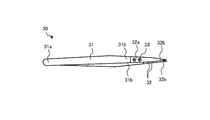
- FIG. 1 is a perspective view of the suction nozzle assembly 10 according to the embodiment
- FIG. 2 is a vertical cross-sectional view of the suction nozzle assembly 10 according to the embodiment.
- the suction nozzle assembly 10 includes a suction nozzle 11 and a flange 12.
- the suction nozzle 11 has a substantially cylindrical shape, and has a through hole 11a, a suction surface 11b, and a mounting portion 11c.
- the through hole 11a is formed from the front end portion A to the rear end portion B of the suction nozzle 11.
- the suction surface 11b is a surface provided on the tip portion A and in contact with the electronic component to be sucked.
- the mounting portion 11c is provided including the rear end portion B, and is a portion to be mounted on the flange 12.
- the flange 12 has a communication hole 12a connected to a through hole 11a of the suction nozzle 11 and an inner peripheral surface 12b, and includes a rear end portion B of the suction nozzle 11 to be included in the flange 12. Is.
- the communication hole 12a of the flange 12 and the through hole 11a of the suction nozzle 11 are connected to function as a suction hole for sucking an electronic component or the like.
- inclusion means that the inner peripheral surfaces 12b of the flange 12 do not have to face each other in all the circumferential directions of the outer circumference of the suction nozzle 11, and the suction nozzle 11 and the flange 12 can be combined.
- the outer peripheral surface of the suction nozzle 11 on the rear end B side may be exposed.
- the suction nozzle 11 is composed of the ceramic structure 1 according to the embodiment.
- the ceramic structure 1 is made of ceramics containing conductive metal oxide particles and has semiconductivity. Ceramic structure 1 according to the embodiment, for example, the resistance value is in the range of 10 3 ( ⁇ ⁇ cm) ⁇ 10 6 ( ⁇ ⁇ cm).
- the ceramic structure 1 according to the embodiment has a surface 1a in which the amount of metal oxide particles distributed is smaller than that inside.
- a surface 1a is, for example, a burnt surface of the ceramic structure 1.
- the "distribution amount of metal oxide particles" is the distribution area of metal oxide particles per unit area.
- the distribution amount of the metal oxide particles on the surface 1a smaller than that inside, the amount of the metal oxide particles having a lower strength than the ceramics as the base material is reduced on the surface 1a.
- the strength of 1a can be improved.
- the surface 11c1 of the mounting portion 11c in the suction nozzle 11 corresponds to the surface 1a of the ceramic structure 1.
- the strength of the mounting portion 11c can be improved by making the distribution amount of the metal oxide particles on the surface 11c1 of the mounting portion 11c smaller than that inside.
- the suction nozzle 11 can be firmly attached to the flange 12.
- the amount of the metal oxide particles desorbed from the surface 1a can be reduced.
- the inner wall surface 11a1 of the through hole 11a in the suction nozzle 11 corresponds to the surface 1a of the ceramic structure 1.
- the metal oxide particles on the inner wall surface 11a1 of the through hole 11a are desorbed from the inner wall surface 11a1 when the electronic component is sucked. It can be suppressed.
- the ceramic structure 1 according to the embodiment may have a surface 1b in which the distribution amount of metal oxide particles is substantially equal to that inside.
- the surface 1b is, for example, a polished surface obtained by polishing the burnt surface of the ceramic structure 1.
- the distribution amount of the metal oxide particles on the surface 1b can be made larger than that on the surface 1a, which is the burnt surface.
- the electrical conductivity can be improved more than the electrical conductivity of the surface 1a.
- the suction surface 11b of the suction nozzle 11 corresponds to the surface 1b of the ceramic structure 1.
- the main component of the adsorption nozzle 11, that is, the ceramic structure 1 may be zirconia (ZrO 2 ), alumina (Al 2 O 3 ), zirconia-alumina composite, or silicon carbide (SiC). Thereby, high mechanical properties can be imparted to the ceramic structure 1.
- the “main component” in the present disclosure is 55% by mass or more when the total amount of the constituent components is 100% by mass.
- the main component is a zirconia-alumina composite
- the total content of zirconia and alumina is 55% by mass or more, and not only those having a large content of zirconia but also alumina. It may have a high content of.
- the main component of the metal oxide particles contained in the ceramic structure 1 is preferably iron oxide (Fe 2 O 3 ), chromium oxide (Cr 2 O 3 ) or titanium oxide (TIO 2 ).
- iron oxide Fe 2 O 3
- Cr 2 O 3 chromium oxide
- Ti 2 titanium oxide
- semiconductivity can be imparted to the ceramic structure 1 having high mechanical properties.
- the suction nozzle assembly 10 since the semi-conductive ceramic structure 1 is applied to the suction nozzle 11, the period from sucking the electronic component to setting it on the circuit board is The adsorbed electronic components can be appropriately statically eliminated.
- the flange 12 is made of a metal member such as stainless steel or an aluminum alloy.
- the suction nozzle 11 and the flange 12 may be integrated by being fitted together, or may be integrated by using an adhesive.
- the adhesive is provided with conductivity. As a result, the static electricity removed from the electronic component can be released to the flange 12 via the adhesive, so that the static electricity can be stably removed from the electronic component.
- the target to which the above-mentioned ceramic structure 1 can be applied is not limited to the suction nozzle 11 of the suction nozzle assembly 10. Therefore, in the following embodiments, an example in which the ceramic structure 1 is applied to various other objects will be described.
- FIG. 3 is a perspective view of the cutter 20 according to the embodiment
- FIG. 4 is a cross-sectional view of the cutter 20 according to the embodiment.
- FIGS. 3 and 4 show a configuration in which the cover tape 25 of the electronic component storage tape 23 in which the chip-shaped electronic component 27 is stored is cut by the cutter 20.
- the cutter 20 is composed of the ceramic structure 1 according to the embodiment. As shown in FIG. 4, the cutter 20 has a mounting portion 21 attached to a supporting means (not shown) and a cutting edge 22 that has been subjected to a blade attachment process.
- the electronic component storage tape 23 is composed of a tape body 24 having a plurality of storage holes 28 for the electronic components 27, and a cover tape 25 covering the upper part of the tape body 24 including the storage holes 28.
- the cutter 20 is erected and arranged along the transport direction of the electronic component storage tape 23, and is located at the center of the cover tape 25 in the lateral direction in FIGS. 3 and 4. An example is shown, and the position P where the cover tape 25 is peeled off from the tape body 24 is indicated by a chain double-dashed line. In cutting, it is preferable to use the cover tape pressing means 26 to suppress the floating of the cover tape 25.
- cover tape 25 divided into the two is wound by the cover tape winding means (not shown), so that the cover tape 25 can be peeled off from the tape main body 24.
- the distribution amount of the metal oxide particles on the surface of the mounting portion 21 is smaller than the distribution amount of the metal oxide particles inside. As a result, the strength of the mounting portion 21 can be improved, so that the cutter 20 can be firmly mounted on the supporting means.
- the distribution amount of the metal oxide particles on the surface of the cutting edge 22 is substantially equal to the distribution amount of the metal oxide particles inside.
- the electrical conductivity of the cutting edge 22 can be improved, so that static electricity can be efficiently removed from each part of the electronic component storage tape 23 that comes into contact with the cutting edge 22.
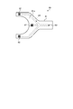
- FIG. 5 is a perspective view of the tweezers 30 according to the embodiment.
- the tweezers 30 has a leg portion 31, a pair of grip portions 32, and a plurality of fixing members 33.
- the leg portion 31 has a plate-like body extending from the base end portion 31a to the pair of tip portions 31b in a bifurcated shape, and is opened and closed so that the pair of tip portions 31b are brought into contact with each other.
- the leg portion 31 is made of metal, plastic, or the like.
- the pair of grip portions 32 are attached to the pair of tip portions 31b of the leg portion 31, respectively, and grip the article by closing the leg portions 31.
- the grip portion 32 has a mounting portion 32a that is attached to the tip end portion 31b of the leg portion 31 using the fixing member 33, and a contact portion 32b that comes into contact with the article to be gripped.
- the grip portion 32 is composed of the ceramic structure 1 according to the embodiment.
- the distribution amount of the metal oxide particles on the surface of the attachment portion 32a is smaller than the distribution amount of the metal oxide particles inside. As a result, the strength of the attachment portion 32a can be improved, so that the grip portion 32 can be firmly attached to the leg portion 31.
- the distribution amount of the metal oxide particles in the contact portion 32b is substantially equal to the distribution amount of the metal oxide particles inside.
- the electrical conductivity of the contact portion 32b can be improved, so that static electricity can be efficiently removed from the article in contact with the contact portion 32b.
- FIG. 6 is a perspective view of the wear detector 40 according to the embodiment.
- the wear detector 40 includes a sliding body 41 and a resistance detector 42.
- the sliding body 41 is composed of the ceramic structure 1 according to the embodiment, and has a sliding surface 41a that slides with another object (not shown).
- the distribution amount of the metal oxide particles on the sliding surface 41a is smaller than the distribution amount of the metal oxide particles inside.
- the distribution amount of the metal oxide particles on the sliding surface 41a is substantially equal to the distribution amount of the metal oxide particles inside.
- the electric resistance is reduced by sliding and wearing with other objects. Then, in the wear detector 40 according to the embodiment, the change in the electrical resistance on the sliding surface 41a is detected by the resistance detector 42.
- the resistance detector 42 detects the electrical resistance of the sliding surface 41a by bringing a plurality of (two in the figure) movable stylus 43 into contact with the sliding surface 41a. As a result, the change in the electric resistance on the sliding surface 41a can be detected, so that the wear detector 40 can evaluate the wear condition of the sliding surface 41a based on the detected change in the electric resistance. ..
- FIG. 7 is a cross-sectional view of the powder static eliminator 50 according to the embodiment.
- the powder static eliminator 50 includes a holder 51, a plurality of ionizers 52, a wiring 53, and an ammeter 54.
- the holder 51 has a short tube shape and is composed of the ceramic structure 1 according to the embodiment.
- the ionizer 52 is a nozzle type ionizer.
- a plurality of (8 in the figure) ionizers 52 are fixed at equal intervals in the circumferential direction of the holder 51. Further, all the ionizers 52 are electrically connected by the wiring 53.
- the ionizer 52 has a needle electrode 52a, and the needle electrode 52a is grounded via a resistor 52b.
- An ammeter 54 is provided on the ground side of the resistor 52b to measure the value of the current flowing from the needle electrode 52a to the ground side when a corona discharge is generated from the needle tip of the needle electrode 52a. There is.
- the charged powder to be statically eliminated is passed through the inside of the holder 51 to operate the plurality of ionizers 52.
- the ions generated by the plurality of ionizers 52 reach the powder, so that the powder static eliminator 50 can eliminate static electricity from the powder.
- the distribution amount of the metal oxide particles on the surface of the holder 51 is the distribution amount of the metal oxide particles inside. Less than.
- FIG. 8 is a perspective view of the powder manufacturing apparatus 60 according to the embodiment.
- the powder manufacturing apparatus 60 includes a mortar 61, a pestle 62, a conductive sheet 63, and a conductive cable 64.
- the mortar 61 has a recess 61a into which the raw material 65 of the powder can be put, and is composed of the ceramic structure 1 according to the embodiment.
- the mortar 61 is placed on an electrically grounded conductive sheet 63 made of, for example, Cu or Al, and the bottom surface of the mortar 61 is in contact with the conductive sheet 63.
- the pestle 62 is used for mixing or crushing the raw material 65 put into the recess 61a of the mortar 61, and is composed of the ceramic structure 1 according to the embodiment.
- the pestle 62 has a contact portion 62a that is pressed against the raw material 65 placed in the recess 61a of the mortar 61, and a grip portion 62b that is gripped by the operator.
- a conductive cable 64 made of, for example, Cu is connected to the grip portion 62b of the pestle 62 via a conductive adhesive, a connection terminal (not shown), or the like. Further, the other end of the conductive cable 64 is electrically grounded via the conductive sheet 63.
- the raw material 65 placed in the recess 61a of the mortar 61 is crushed by crushing or crushing with the pestle 62, and the crushed raw material 65 is stirred by the pestle 62. Thereby, the powder can be produced from the raw material 65.
- the mortar 61 and the pestle 62 are composed of the semi-conductive ceramic structure 1, the raw material 65 and the raw material 65 are used when producing powder from the raw material 65. It is possible to suppress the generated powder from being charged.
- the distribution amount of the metal oxide particles on the surface of the holder 51 is the metal oxide particles inside. Less than the distribution of.
- the powder when the powder is produced from the raw material 65, it is possible to prevent the metal oxide particles from being desorbed from the surfaces of the mortar 61 and the pestle 62 to generate particles.
- FIGS. 9 and 10 are perspective views of the lift pin 70 according to the embodiment, and FIG. 10 is a cross-sectional view taken along the line XX shown in FIG.
- the lift pin 70 is used in a semiconductor manufacturing apparatus for performing various treatments on a substrate (not shown) such as a wafer, a semiconductor inspection apparatus for inspecting defects on the surface of the substrate, or the like, in which the substrate is separated from the mounting surface. It acts as a supporter. As shown in FIG. 9 and the like, the lift pin 70 has a front end portion 71, a connection portion 72, and a rear end portion 73 in this order from the side in contact with the substrate.
- the tip portion 71 has a mounting portion 71a attached to the connecting portion 72 and a contact surface 71b in contact with the substrate, and is composed of the ceramic structure 1. As described above, since the tip portion 71 in contact with the substrate is composed of the semi-conductive ceramic structure 1, the electric charge accumulated on the substrate can be efficiently flowed to the outside.
- the substrate can be prevented from being lifted from the lift pin 70, and the substrate can be stably supported.
- the mounting portion 71a of the tip portion 71 is joined to the connecting portion 72 by press fitting or a conductive adhesive, and the rear end surface side of the connecting portion 72 is provided with a rear end portion 73 having a continuous screw shape. Further, the connecting portion 72 and the rear end portion 73 are integrally formed of metal.
- the distribution amount of the metal oxide particles on the surface of the attachment portion 71a of the tip portion 71 is smaller than the distribution amount of the metal oxide particles inside.
- the strength of the mounting portion 71a can be improved, so that the tip portion 71 can be mounted more firmly on the connecting portion 72.
- the distribution amount of the metal oxide particles on the contact surface 71b of the tip portion 71 is substantially equal to the distribution amount of the metal oxide particles inside.
- the electrical conductivity of the contact surface 71b can be improved, so that the electric charge accumulated on the substrate can be more efficiently flowed to the outside.
- FIG. 11 is a top view of the transport hand 80 according to the embodiment.
- the transport hand 80 is a hand that transports a substrate in a semiconductor manufacturing apparatus that performs various processes on a substrate (not shown) such as a wafer, a semiconductor inspection apparatus that inspects defects on the surface of the substrate, and the like.
- the transport hand 80 is composed of a substantially Y-shaped substrate 81 when viewed from above, and the substrate 81 is composed of the ceramic structure 1 according to the embodiment. Then, in the transport hand 80, the substrate is placed on the mounting surface 81a of the substrate 81, and the substrate is held by sucking the substrate from the plurality of suction ports 82 formed on the mounting surface 81a.
- a flow path 84 connecting a plurality of suction ports 82 and a suction port 83 connected to a suction means (not shown) is formed inside the substrate 81.
- the base 81 of the transport hand 80 is composed of the ceramic structure 1.
- the substrate 81 in contact with the substrate is composed of the semi-conductive ceramic structure 1, the electric charge accumulated on the substrate can be efficiently flowed to the outside.
- the substrate can be prevented from being lifted from the transport hand 80, and the substrate can be stably held.
- the distribution amount of the metal oxide particles on the inner wall surface of the flow path 84 is smaller than the distribution amount of the metal oxide particles inside. Therefore, according to the embodiment, it is possible to prevent the metal oxide particles from being desorbed from the inner wall surface of the flow path 84 to generate particles when the substrate is adsorbed.
- the distribution amount of the metal oxide particles on the mounting surface 81a of the substrate 81 is substantially equal to the distribution amount of the metal oxide particles inside.
- the electrical conductivity of the mounting surface 81a can be improved, so that the electric charge accumulated on the substrate can be more efficiently flowed to the outside.
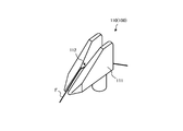
- FIG. 12 is a perspective view of the oiling nozzle 110, which is an example of the fiber guide 100 according to the embodiment.
- the oiling nozzle 110 shown in FIG. 12 is used to attach oil to the sliding fiber F.
- the oiling nozzle 110 includes a main body portion 111 and a groove-shaped thread guide portion 112 located above the main body portion 111 and in contact with the fiber F.
- the thread guide portion 112 includes an introduction portion for introducing the fiber F, an attachment portion for adhering oil to the fiber F, and a delivery portion for delivering the fiber F.
- the main body 111 is composed of the ceramic structure 1.
- the main body 111 in contact with the fiber F is composed of the semi-conductive ceramic structure 1, the static electricity generated by the sliding of the fiber F can be efficiently eliminated.
- the distribution amount of the metal oxide particles on the surface of the thread guide portion 112 is substantially equal to the distribution amount of the metal oxide particles inside.
- the electric conductivity of the thread guide portion 112 can be improved, so that the static electricity generated by the sliding of the fiber F can be efficiently eliminated.
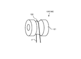
- FIG. 13 is a perspective view of the roller guide 120, which is an example of the fiber guide 100 according to the embodiment.
- the roller guide 120 shown in FIG. 13 guides the fiber F while rotating.
- the roller guide 120 includes a cylindrical main body portion 121 and a V-groove-shaped thread guide portion 122 located on the side surface of the main body portion 121 and in contact with the fiber F.
- the main body 121 is composed of the ceramic structure 1.
- the main body portion 121 in contact with the fiber F is composed of the semi-conductive ceramic structure 1, the static electricity generated by the sliding of the fiber F can be efficiently eliminated.
- the distribution amount of the metal oxide particles on the surface of the thread guide portion 122 is substantially equal to the distribution amount of the metal oxide particles inside.
- the electric conductivity of the thread guide portion 122 can be improved, so that the static electricity generated by the sliding of the fiber F can be efficiently eliminated.
- FIG. 14 is a perspective view of a rod guide 130, which is an example of the fiber guide 100 according to the embodiment.
- the rod guide 130 shown in FIG. 14 is used for converging and separating the fibers F.
- the rod guide 130 includes a cylindrical main body 131 and a thread guide 132 located on the side surface of the main body 131.
- the main body 131 is composed of the ceramic structure 1.
- the main body 131 in contact with the fiber F is composed of the semi-conductive ceramic structure 1, the static electricity generated by the sliding of the fiber F can be efficiently eliminated.
- the distribution amount of the metal oxide particles on the surface of the thread guide portion 132 is substantially equal to the distribution amount of the metal oxide particles inside.
- the electric conductivity of the thread guide portion 132 can be improved, so that the static electricity generated by the sliding of the fiber F can be efficiently eliminated.
- FIG. 15 is a perspective view of the traverse guide 140, which is an example of the fiber guide 100 according to the embodiment.
- the traverse guide 140 shown in FIG. 15 is used as a guide when winding the fiber F around the outer circumference of the cylindrical package.
- the traverse guide 140 includes a main body portion 141 and a U-groove-shaped thread guide portion 142 located above the main body portion 141 and in contact with the fiber F.
- the main body 141 is composed of the ceramic structure 1.
- the main body portion 141 in contact with the fiber F is composed of the semi-conductive ceramic structure 1, the static electricity generated by the sliding of the fiber F can be efficiently eliminated.
- the distribution amount of the metal oxide particles on the surface of the thread guide portion 142 is substantially equal to the distribution amount of the metal oxide particles inside.
- the electric conductivity of the thread guide portion 142 can be improved, so that the static electricity generated by the sliding of the fiber F can be efficiently eliminated.
- iron oxide powder which is a conductivity-imparting agent and becomes metal oxide particles distributed in the ceramic structure 1 and powders of chromium oxide and titanium oxide which are additives are added. It was mixed in a predetermined ratio. Then, a predetermined amount of solvent was added to the prepared mixed powder and pre-pulverized with a rotary mill to obtain a second slurry.
- the particle size distribution of the pre-crushed mixed powder was measured by the above-mentioned laser diffraction type particle size distribution device, and the cumulative 50% particle size (D50) was determined to be 0.258 ⁇ m.
- the first slurry and the second slurry are mixed so that the ratio of zirconia: iron oxide: chromium oxide: titanium oxide is 69.6: 27.0: 3.0: 0.4 (mass%).
- the prepared slurry was mainly pulverized with a rotary mill.
- the particle size distribution of the pulverized slurry was measured by the above-mentioned laser diffraction type particle size distribution device, and the cumulative 50% particle size (D50) was determined to be 0.235 ⁇ m.
- a predetermined amount of various binders was added to the obtained slurry and dried by a spray drying method to obtain granules. Then, the obtained granules were used to obtain a molded product having a desired shape by a desired molding method, for example, a dry pressure molding method, a cold hydrostatic pressure molding method, or the like.
- the obtained molded product was held at a temperature of 1300 to 1450 ° C. for 1 to 3 hours and fired in an air atmosphere to obtain the ceramic structure 1 of the present disclosure.
- the reason why the firing temperature was set to 1300 to 1450 ° C. is that if the firing temperature is less than 1300 ° C., a dense sintered body cannot be obtained, and if the firing temperature exceeds 1450 ° C., the crystal grain size becomes large due to grain growth. This is because the mechanical properties of the ceramic structure 1 tend to deteriorate.
- impurities different from the above-mentioned components may be mixed in the raw material powder or in the manufacturing process, but these may be contained as long as they are 2.0 parts by mass or less.
- the surface 1a which is the burnt skin surface, was observed with an SEM (Scanning Electron Microscope). Further, a predetermined portion of the obtained sample was polished, and the polished surface was regarded as the inside of the ceramic structure 1 and observed by SEM in the same manner.
- FIG. 16 is an SEM observation photograph of the surface 1a of the ceramic structure 1
- FIG. 17 is an SEM observation photograph of the inside of the ceramic structure 1.
- the dark-colored portions indicate the metal oxide particles.
- the ceramic structure 1 according to the embodiment has a surface 1a in which the distribution amount of the metal oxide particles is smaller than that inside.
- the zirconia powder which is the main component, is crushed finer than the powder of other components (iron oxide, chromium oxide, and titanium oxide) and then fired, so that the zirconia, which is the main component on the surface, is more than the other components. Since it is sintered first, it is presumed that other components are difficult to fire on the surface.
- the ceramic structure 1 shown in FIG. 17 is in the same state as the surface 1b which is the polished surface of the ceramic structure 1, the ceramic structure 1 whose surface is polished is made of metal oxide particles. It can be seen that the surface 1b has a distribution amount substantially equal to that of the inside.
- the present disclosure is not limited to the above embodiments, and various changes can be made as long as the purpose is not deviated.
- the surface 1a of the ceramic structure 1 is exposed and applied to various objects is shown, but the surface 1a may be further coated with a conductive coating and applied to various objects. ..
- DLC diamond-like carbon
- Teflon registered trademark
- silicon etc. to which a conductive component is added
- the ceramic structure 1 while maintaining the semi-conductive property of the ceramic structure 1, it is possible to suppress the desorption of inclusions such as iron oxide from the surface 1a to the outside. Therefore, it is possible to prevent the inclusions of the ceramic structure 1 from being desorbed as impurities in an environment where impurities are disliked, such as in a semiconductor manufacturing process or precision analysis.
- the conductive component metal oxide particles
Landscapes
- Chemical & Material Sciences (AREA)
- Engineering & Computer Science (AREA)
- Ceramic Engineering (AREA)
- Manufacturing & Machinery (AREA)
- Composite Materials (AREA)
- Materials Engineering (AREA)
- Structural Engineering (AREA)
- Organic Chemistry (AREA)
- Mechanical Engineering (AREA)
- Physics & Mathematics (AREA)
- Plasma & Fusion (AREA)
- General Physics & Mathematics (AREA)
- Robotics (AREA)
- Inorganic Chemistry (AREA)
- Life Sciences & Earth Sciences (AREA)
- Forests & Forestry (AREA)
- Supply And Installment Of Electrical Components (AREA)
- Elimination Of Static Electricity (AREA)
- Gripping Jigs, Holding Jigs, And Positioning Jigs (AREA)
- Nonmetal Cutting Devices (AREA)
- Crushing And Grinding (AREA)
- Container, Conveyance, Adherence, Positioning, Of Wafer (AREA)
Abstract
セラミック構造体(1)は、導電性の金属酸化物粒子を含有するセラミックスで構成され、金属酸化物粒子の分布量が内部よりも少ない表面(1a)を有する。
Description
開示の実施形態は、セラミック構造体、吸着ノズル、カッター、ピンセット、摩耗検出器、粉体除電装置、粉体製造装置、リフトピン、搬送ハンドおよび繊維ガイドに関する。
従来、機械的特性に優れるセラミック材料の内部に金属酸化物粒子を分布させることにより、絶縁性と導電性との中間の電気伝導性(以下、「半導電性」とも呼称する。)を有するセラミック構造体が知られている(例えば、特許文献1参照)。
実施形態の一態様に係るセラミック構造体は、導電性の金属酸化物粒子を含有するセラミックスで構成され、前記金属酸化物粒子の分布量が内部よりも少ない表面を有する。
以下、添付図面を参照して、本願の開示するセラミック構造体、吸着ノズル、カッター、ピンセット、摩耗検出器、粉体除電装置、粉体製造装置、リフトピン、搬送ハンドおよび繊維ガイドの実施形態について説明する。なお、以下に示す実施形態によりこの開示が限定されるものではない。
従来、機械的特性に優れるセラミック材料の内部に金属酸化物粒子を分布させることにより、絶縁性と導電性との中間の電気伝導性(以下、「半導電性」とも呼称する。)を有するセラミック構造体が知られている。
たとえば、チップ状の電子部品を実装するために用いられるセラミックスの吸着ノズルに半導電性を付与することにより、電子部品が吸着された際に、かかる電子部品に帯電する静電気を除去することができる。
しかしながら、従来の技術では、セラミック構造体の表面にも多くの金属酸化物粒子が分布していることから、かかる金属酸化物粒子に起因して、セラミック構造体の表面強度が低下するなどの問題があった。
また、従来の技術では、表面に分布する金属酸化物粒子が脱離して、かかる脱離した金属酸化物粒子が不純物(パーティクル)となる恐れがあった。
そこで、上述の問題点を克服し、半導電性を有するとともに、表面の強度を向上させることができるセラミック構造体の実現が期待されている。
<吸着ノズル組み立て体>
最初に、実施形態に係るセラミック構造体1を適用した吸着ノズル組み立て体10の構成について、図1および図2を参照しながら説明する。図1は、実施形態に係る吸着ノズル組み立て体10の斜視図であり、図2は、実施形態に係る吸着ノズル組み立て体10の縦断面図である。
最初に、実施形態に係るセラミック構造体1を適用した吸着ノズル組み立て体10の構成について、図1および図2を参照しながら説明する。図1は、実施形態に係る吸着ノズル組み立て体10の斜視図であり、図2は、実施形態に係る吸着ノズル組み立て体10の縦断面図である。
図1などに示すように、実施形態に係る吸着ノズル組み立て体10は、吸着ノズル11と、フランジ12とを備える。吸着ノズル11は、略円筒形状を有し、貫通孔11aと、吸着面11bと、取付部11cとを有する。
貫通孔11aは、吸着ノズル11の先端部Aから後端部Bにわたって形成される。吸着面11bは、先端部Aに設けられ、吸着する電子部品と接する面である。取付部11cは、後端部Bを含んで設けられ、フランジ12に取り付けられる部位である。
フランジ12は、図2に示すように、吸着ノズル11の貫通孔11aに繋がる連通孔12aと、内周面12bとを有し、吸着ノズル11の後端部Bを含んで内包する筒状体である。
そして、実施形態に係る吸着ノズル組み立て体10では、フランジ12が有する連通孔12aと、吸着ノズル11が有する貫通孔11aとがつながることにより、電子部品などを吸着するための吸引孔として機能する。
なお、「内包」とは、吸着ノズル11の外周の周方向すべてにフランジ12の内周面12bが対向している必要はなく、吸着ノズル11とフランジ12とを組み合わせることができるのであれば、吸着ノズル11の後端部B側の外周面が露出しているものであってもよい。
吸着ノズル11は、実施形態に係るセラミック構造体1で構成される。かかるセラミック構造体1は、導電性の金属酸化物粒子を含有するセラミックスで構成され、半導電性を有する。実施形態に係るセラミック構造体1は、たとえば、抵抗値が103(Ω・cm)~106(Ω・cm)の範囲である。
ここで、実施形態に係るセラミック構造体1は、金属酸化物粒子の分布量が内部よりも少ない表面1aを有する。かかる表面1aは、たとえば、セラミック構造体1の焼き肌面である。なお、本開示において、「金属酸化物粒子の分布量」とは、単位面積当たりの金属酸化物粒子の分布面積のことである。
このように、表面1aにおける金属酸化物粒子の分布量を内部よりも少なくすることにより、かかる表面1aにおいて基材となるセラミックスよりも強度の低い金属酸化物粒子の量が少なくなることから、表面1aの強度を向上させることができる。
たとえば、吸着ノズル11における取付部11cの表面11c1が、セラミック構造体1の表面1aに対応する。このように、取付部11cの表面11c1における金属酸化物粒子の分布量を内部よりも少なくすることにより、取付部11cの強度を向上させることができる。
したがって、実施形態によれば、吸着ノズル11をフランジ12に強固に取り付けることができる。
また、表面1aにおける金属酸化物粒子の分布量を内部よりも少なくすることにより、かかる表面1aから脱離する金属酸化物粒子の量を低減させることができる。
たとえば、吸着ノズル11における貫通孔11aの内壁面11a1が、セラミック構造体1の表面1aに対応する。このように、貫通孔11aの内壁面11a1における金属酸化物粒子の分布量を内部よりも少なくすることにより、電子部品を吸引する際に、内壁面11a1から金属酸化物粒子が脱離することを抑制することができる。
したがって、実施形態によれば、貫通孔11a内において金属酸化物粒子が脱離してパーティクルとなることを抑制することができる。
また、実施形態に係るセラミック構造体1は、金属酸化物粒子の分布量が内部と略等しい表面1bを有してもよい。かかる表面1bは、たとえば、セラミック構造体1の焼き肌面を研磨した研磨面である。
このように、表面1bにおける金属酸化物粒子の分布量を内部と略等しくすることにより、焼き肌面である表面1aよりも金属酸化物粒子の分布量を多くすることができることから、表面1bの電気伝導率を表面1aの電気伝導率よりも向上させることができる。
たとえば、吸着ノズル11の吸着面11bが、セラミック構造体1の表面1bに対応する。このように、吸着面11bにおける金属酸化物粒子の分布量を内部と略等しくすることにより、吸着面11bに接触する電子部品から静電気を効率よく除電することができる。
つづいて、吸着ノズル11の詳細について説明する。吸着ノズル11、すなわち、セラミック構造体1の主成分は、ジルコニア(ZrO2)、アルミナ(Al2O3)、ジルコニア-アルミナ複合物または炭化珪素(SiC)であるとよい。これにより、セラミック構造体1に高い機械的特性を付与することができる。
なお、本開示における「主成分」とは、構成する成分の全体を100質量%とした場合、55質量%以上のことである。なお、「ジルコニア-アルミナ複合物が主成分である」とは、ジルコニアとアルミナとの含有量の合計が55質量%以上であるもののことであり、ジルコニアの含有量が多いもののみならず、アルミナの含有量が多いものであってもよい。
また、セラミック構造体1に含まれる金属酸化物粒子の主成分は、酸化鉄(Fe2O3)、酸化クロム(Cr2O3)または酸化チタン(TiO2)であるとよい。これにより、高い機械的特性を有するセラミック構造体1に半導電性を付与することができる。
たとえば、吸着ノズル11が導電性材料で構成されている場合、電子部品から過度に静電気が除電されることから、かかる静電気に起因してスパークが発生する恐れがある。一方で、吸着ノズル11が絶縁性材料で構成されている場合、電子部品から静電気をまったく除電することができない。
しかしながら、実施形態に係る吸着ノズル組み立て体10では、吸着ノズル11に半導電性のセラミック構造体1が適用されていることから、電子部品を吸着してから回路基板にセットするまでの間に、吸着された電子部品を適度に除電することができる。
フランジ12は、たとえば、ステンレスやアルミニウム合金などの金属部材で構成される。なお、吸着ノズル組み立て体10において、吸着ノズル11とフランジ12とは、嵌め合わされることにより一体化されてもよいし、接着剤を用いて一体化されてもよい。
また、吸着ノズル11とフランジ12とが接着剤を用いて一体化される場合、かかる接着剤には導電性が付与されるとよい。これにより、かかる接着剤を介して電子部品から除電された静電気をフランジ12に逃がすことができることから、電子部品から静電気を安定して除電することができる。
<カッター>
上述のセラミック構造体1が適用可能な対象は、吸着ノズル組み立て体10の吸着ノズル11に限られない。そこで、以降の実施形態では、セラミック構造体1をその他の各種対象に適用した例について示す。
上述のセラミック構造体1が適用可能な対象は、吸着ノズル組み立て体10の吸着ノズル11に限られない。そこで、以降の実施形態では、セラミック構造体1をその他の各種対象に適用した例について示す。
まずは、実施形態に係るセラミック構造体1を適用したカッター20の構成について、図3および図4を参照しながら説明する。図3は、実施形態に係るカッター20の斜視図であり、図4は、実施形態に係るカッター20の断面図である。
なお、図3および図4は、チップ状の電子部品27が収納された電子部品収納テープ23のカバーテープ25をカッター20により切断する構成について示している。
カッター20は、実施形態に係るセラミック構造体1で構成される。図4に示すように、カッター20は、図示しない支持手段に取り付けられる取付部21と、刃付け加工が施された刃先22とを有する。
また、図3に示すように、電子部品収納テープ23は、電子部品27の収納穴28を複数有するテープ本体24と、収納穴28を含めテープ本体24の上部を覆うカバーテープ25とで構成される。
そして、カッター20は、電子部品収納テープ23の搬送方向に沿うように立てられて配置されるものであり、図3および図4においては、カバーテープ25の短手方向の中央に位置している例を示し、テープ本体24からカバーテープ25が剥離される位置Pを二点鎖線で示している。なお、切断にあたっては、カバーテープ押さえ手段26を用いて、カバーテープ25の浮きを抑えることが好適である。
つづいては、カッター20によりカバーテープ25を切断し、カバーテープ25をテープ本体24から剥離する工程について説明する。まず、電子部品収納テープ23が搬送されることで、カッター20の刃先22によりカバーテープ25が2つに分割されるように切断される。
そして、この2つに分割されたカバーテープ25がそれぞれカバーテープ巻き取り手段(図示せず)により巻き取られることで、カバーテープ25をテープ本体24から剥離することができる。
ここで、実施形態に係るカッター20では、取付部21の表面における金属酸化物粒子の分布量が、内部における金属酸化物粒子の分布量よりも少ない。これにより、取付部21の強度を向上させることができることから、カッター20を支持手段に強固に取り付けることができる。
また、実施形態に係るカッター20では、刃先22の表面における金属酸化物粒子の分布量が、内部における金属酸化物粒子の分布量と略等しい。これにより、刃先22の電気伝導率を向上させることができることから、刃先22に接触する電子部品収納テープ23の各部から静電気を効率よく除電することができる。
<ピンセット>
つづいて、実施形態に係るセラミック構造体1を適用したピンセット30の構成について、図5を参照しながら説明する。図5は、実施形態に係るピンセット30の斜視図である。
つづいて、実施形態に係るセラミック構造体1を適用したピンセット30の構成について、図5を参照しながら説明する。図5は、実施形態に係るピンセット30の斜視図である。
図5に示すように、実施形態に係るピンセット30は、脚部31と、一対の把持部32と、複数の固定部材33とを有する。脚部31は、基端部31aから一対の先端部31bに渡って板状体が二股状に延伸しており、かかる一対の先端部31bが互いに接離するように開閉操作される。脚部31は、金属やプラスチックなどで構成されている。
一対の把持部32は、脚部31における一対の先端部31bにそれぞれ取り付けられ、脚部31を閉じることにより物品を把持する。把持部32は、固定部材33を用いて脚部31の先端部31bに取り付けられる取付部32aと、把持される物品と接触する接触部32bとを有する。
把持部32は、実施形態に係るセラミック構造体1で構成される。そして、実施形態に係る把持部32では、取付部32aの表面における金属酸化物粒子の分布量が、内部における金属酸化物粒子の分布量よりも少ない。これにより、取付部32aの強度を向上させることができることから、把持部32を脚部31に強固に取り付けることができる。
また、実施形態に係る把持部32では、接触部32bにおける金属酸化物粒子の分布量が、内部における金属酸化物粒子の分布量と略等しい。これにより、接触部32bの電気伝導率を向上させることができることから、接触部32bに接触する物品から静電気を効率よく除電することができる。
<摩耗検出器>
つづいて、実施形態に係るセラミック構造体1を適用した摩耗検出器40の構成について、図6を参照しながら説明する。図6は、実施形態に係る摩耗検出器40の斜視図である。
つづいて、実施形態に係るセラミック構造体1を適用した摩耗検出器40の構成について、図6を参照しながら説明する。図6は、実施形態に係る摩耗検出器40の斜視図である。
摩耗検出器40は、摺動体41と、抵抗検出器42とを備える。摺動体41は、実施形態に係るセラミック構造体1で構成され、他の物体(図示せず)と摺動する摺動面41aを有する。
ここで、実施形態に係る摺動体41の摺動面41aが摩耗していない場合、摺動面41aにおける金属酸化物粒子の分布量は、内部における金属酸化物粒子の分布量よりも少ない。一方で、摺動面41aが他の物体と摺動して摩耗した場合、摺動面41aにおける金属酸化物粒子の分布量は、内部における金属酸化物粒子の分布量と略等しくなる。
すなわち、摺動体41の摺動面41aでは、他の物体と摺動して摩耗することによって電気抵抗が小さくなる。そして、実施形態に係る摩耗検出器40では、摺動面41aにおける電気抵抗の変化を抵抗検出器42で検出する。
具体的には、抵抗検出器42は、複数(図では2個)の可動式の触針43を摺動面41aに接触させることにより、摺動面41aの電気抵抗を検出する。これにより、摺動面41aにおける電気抵抗の変化を検出することができることから、摩耗検出器40は、検出された電気抵抗の変化に基づいて、摺動面41aの摩耗具合を評価することができる。
<粉体除電装置>
つづいて、実施形態に係るセラミック構造体1を適用した粉体除電装置50の構成について、図7を参照しながら説明する。図7は、実施形態に係る粉体除電装置50の断面図である。
つづいて、実施形態に係るセラミック構造体1を適用した粉体除電装置50の構成について、図7を参照しながら説明する。図7は、実施形態に係る粉体除電装置50の断面図である。
実施形態に係る粉体除電装置50は、ホルダー51と、複数のイオナイザー52と、配線53と、電流計54とを備える。ホルダー51は、短管形状を有し、実施形態に係るセラミック構造体1で構成される。
イオナイザー52は、ノズル型のイオナイザーである。図7の例では、複数(図では8個)のイオナイザー52がホルダー51の周方向に等間隔に固定される。また、すべてのイオナイザー52は、配線53で電気的に接続されている。
イオナイザー52は、針電極52aを有し、かかる針電極52aは、抵抗52bを介して接地されている。なお、抵抗52bよりも接地側には、針電極52aの針先からコロナ放電が発生したときに、かかる針電極52aから接地側に流れる電流の値を測定するための電流計54が設けられている。
そして、ホルダー51の内部に除電対象となる帯電した粉体を通流させ、複数のイオナイザー52を動作させる。これにより、かかる複数のイオナイザー52で発生したイオンが粉体に届くことから、粉体除電装置50は、粉体を除電することができる。
そして、実施形態に係る粉体除電装置50では、ホルダー51がセラミック構造体1で構成されることから、ホルダー51の表面における金属酸化物粒子の分布量が、内部における金属酸化物粒子の分布量よりも少ない。
したがって、実施形態によれば、帯電した粉体を通流させる際に、ホルダー51の表面から金属酸化物粒子が脱離してパーティクルが発生することを抑制することができる。
<粉体製造装置>
つづいて、実施形態に係るセラミック構造体1を適用した粉体製造装置60の構成について、図8を参照しながら説明する。図8は、実施形態に係る粉体製造装置60の斜視図である。
つづいて、実施形態に係るセラミック構造体1を適用した粉体製造装置60の構成について、図8を参照しながら説明する。図8は、実施形態に係る粉体製造装置60の斜視図である。
図8に示すように、実施形態に係る粉体製造装置60は、乳鉢61と、乳棒62と、導電性シート63と、導電性ケーブル64とを備える。乳鉢61は、粉末の原料65を投入可能な凹部61aを有し、実施形態に係るセラミック構造体1で構成される。
また、乳鉢61は、電気的に接地された、たとえばCuやAlで構成される導電性シート63の上に載置されており、かかる導電性シート63に乳鉢61の底面が当接している。
乳棒62は、乳鉢61の凹部61aに投入された原料65の混和または粉砕に用いられ、実施形態に係るセラミック構造体1で構成される。乳棒62は、乳鉢61の凹部61aに入れられた原料65に押し付けられる当接部62aと、作業者によって把持される把持部62bとを有する。
乳棒62の把持部62bには、たとえばCuで構成される導電性ケーブル64の一方端が、導電性接着剤や図示しない接続端子などを介して接続されている。また、導電性ケーブル64の他方端は、導電性シート63を介して電気的に接地されている。
そして、実施形態に係る粉体製造装置60では、乳鉢61の凹部61aに入れられた原料65を、乳棒62によって摺り潰したり叩き潰すことで粉砕しつつ、粉砕した原料65を乳棒62によって掻き混ぜることにより、原料65から粉体を製造することができる。
ここで、実施形態に係る粉体製造装置60では、乳鉢61および乳棒62が半導電性を有するセラミック構造体1で構成されることから、原料65から粉体を製造する際に、原料65や生成される粉体が帯電することを抑制することができる。
さらに、実施形態に係る粉体製造装置60では、乳鉢61および乳棒62がセラミック構造体1で構成されることから、ホルダー51の表面における金属酸化物粒子の分布量が、内部における金属酸化物粒子の分布量よりも少ない。
したがって、実施形態によれば、原料65から粉体を製造する際に、乳鉢61や乳棒62の表面から金属酸化物粒子が脱離してパーティクルが発生することを抑制することができる。
<リフトピン>
つづいて、実施形態に係るセラミック構造体1を適用したリフトピン70の構成について、図9および図10を参照しながら説明する。図9は、実施形態に係るリフトピン70の斜視図であり、図10は、図9に示すX-X線の矢視断面図である。
つづいて、実施形態に係るセラミック構造体1を適用したリフトピン70の構成について、図9および図10を参照しながら説明する。図9は、実施形態に係るリフトピン70の斜視図であり、図10は、図9に示すX-X線の矢視断面図である。
実施形態に係るリフトピン70は、ウェハなどの基板(図示せず)に各種処理を施す半導体製造装置や、基板の表面の欠陥を検査する半導体検査装置などにおいて、基板を載置面から離隔させて支持する作用をなすものである。図9などに示すように、リフトピン70は、基板と接触する側から順に、先端部71と、接続部72と、後端部73とを有する。
図10に示すように、先端部71は、接続部72に取り付けられる取付部71aと、基板と接触する接触面71bとを有し、セラミック構造体1で構成される。このように、基板と接触する先端部71が半導電性を有するセラミック構造体1で構成されることにより、基板に蓄積した電荷を外部に効率よく流すことができる。
したがって、実施形態によれば、基板がリフトピン70から浮き上がることを防止し、安定して基板を支持することができる。
先端部71の取付部71aは、圧入や導電性接着剤によって接続部72に接合されており、接続部72の後端面側には連続してネジ形状をなす後端部73を備える。また、接続部72および後端部73は、金属で一体的に形成されている。
接続部72は、先端部71側の端面の径が先端部71の後端面の径(=後端部73側の径)よりも大きい径を有するとよい。これにより、半導電性セラミックスの先端部71を金属の接続部72に圧入によって強固に接合することができる。
そして、先端部71と接続部72の接合に圧入を用いることによって、接着剤で接合した場合に比較してより強固に、かつリフトピン70全体の導電性を失うことなく接合することができる。
ここで、実施形態に係るリフトピン70では、先端部71の取付部71aの表面における金属酸化物粒子の分布量が、内部における金属酸化物粒子の分布量よりも少ない。これにより、取付部71aの強度を向上させることができることから、先端部71を接続部72にさらに強固に取り付けることができる。
また、実施形態に係るリフトピン70では、先端部71の接触面71bにおける金属酸化物粒子の分布量が、内部における金属酸化物粒子の分布量と略等しい。これにより、接触面71bの電気伝導率を向上させることができることから、基板に蓄積した電荷を外部にさらに効率よく流すことができる。
<搬送ハンド>
つづいて、実施形態に係るセラミック構造体1を適用した搬送ハンド80の構成について、図11を参照しながら説明する。図11は、実施形態に係る搬送ハンド80の上面図である。
つづいて、実施形態に係るセラミック構造体1を適用した搬送ハンド80の構成について、図11を参照しながら説明する。図11は、実施形態に係る搬送ハンド80の上面図である。
実施形態に係る搬送ハンド80は、ウェハなどの基板(図示せず)に各種処理を施す半導体製造装置や、基板の表面の欠陥を検査する半導体検査装置などにおいて、基板を搬送するハンドである。
搬送ハンド80は、上面視で略Y字形状の基体81で構成され、かかる基体81は、実施形態に係るセラミック構造体1で構成される。そして、搬送ハンド80では、基体81の載置面81aに基板を載置し、かかる載置面81aに形成される複数の吸着口82から基板を吸着することで基板を保持する。
そして、基体81の内部には、複数の吸着口82と、図示しない吸引手段に接続される吸引口83との間をつなぐ流路84が形成される。
ここで、実施形態では、搬送ハンド80の基体81がセラミック構造体1で構成される。このように、基板と接触する基体81が半導電性を有するセラミック構造体1で構成されることにより、基板に蓄積した電荷を外部に効率よく流すことができる。
したがって、実施形態によれば、基板が搬送ハンド80から浮き上がることを防止し、安定して基板を保持することができる。
また、実施形態では、流路84の内壁面における金属酸化物粒子の分布量が、内部における金属酸化物粒子の分布量よりも少ない。したがって、実施形態によれば、基板を吸着させる際に、流路84の内壁面から金属酸化物粒子が脱離してパーティクルが発生することを抑制することができる。
また、実施形態では、基体81の載置面81aにおける金属酸化物粒子の分布量が、内部における金属酸化物粒子の分布量と略等しい。これにより、載置面81aの電気伝導率を向上させることができることから、基板に蓄積した電荷を外部にさらに効率よく流すことができる。
<繊維ガイド>
つづいて、実施形態に係るセラミック構造体1を適用した繊維ガイド100の構成について、図12~図15を参照しながら説明する。図12は、実施形態に係る繊維ガイド100の一例であるオイリングノズル110の斜視図である。
つづいて、実施形態に係るセラミック構造体1を適用した繊維ガイド100の構成について、図12~図15を参照しながら説明する。図12は、実施形態に係る繊維ガイド100の一例であるオイリングノズル110の斜視図である。
図12に示すオイリングノズル110は、摺動する繊維Fにオイルを付着させるのに用いられるものである。図12に示すように、オイリングノズル110は、本体部111と、かかる本体部111の上部に位置し、繊維Fと接する溝状の導糸部112とを備える。この導糸部112は、繊維Fを導入する導入部、繊維Fにオイルを付着させる付着部、および繊維Fを送出する送出部を備える。
ここで、実施形態に係るオイリングノズル110では、本体部111がセラミック構造体1で構成される。このように、繊維Fと接触する本体部111が半導電性を有するセラミック構造体1で構成されることにより、繊維Fが摺動することで発生する静電気を効率よく除電することができる。
また、実施形態に係るオイリングノズル110では、導糸部112の表面における金属酸化物粒子の分布量が、内部における金属酸化物粒子の分布量と略等しい。これにより、導糸部112の電気伝導率を向上させることができることから、繊維Fが摺動することで発生する静電気を効率よく除電することができる。
図13は、実施形態に係る繊維ガイド100の一例であるローラガイド120の斜視図である。図13に示すローラガイド120は、回転しながら繊維Fを案内するものである。図13に示すように、ローラガイド120は、円筒状の本体部121と、かかる本体部121の側面に位置し、繊維Fと接するV溝状の導糸部122とを備える。
ここで、実施形態に係るローラガイド120では、本体部121がセラミック構造体1で構成される。このように、繊維Fと接触する本体部121が半導電性を有するセラミック構造体1で構成されることにより、繊維Fが摺動することで発生する静電気を効率よく除電することができる。
また、実施形態に係るローラガイド120では、導糸部122の表面における金属酸化物粒子の分布量が、内部における金属酸化物粒子の分布量と略等しい。これにより、導糸部122の電気伝導率を向上させることができることから、繊維Fが摺動することで発生する静電気を効率よく除電することができる。
図14は、実施形態に係る繊維ガイド100の一例であるロッドガイド130の斜視図である。図14に示すロッドガイド130は、繊維Fを収束したり分離したりするために使用されるものである。図14に示すように、ロッドガイド130は、円筒状の本体部131と、かかる本体部131の側面に位置する導糸部132とを備える。
ここで、実施形態に係るロッドガイド130では、本体部131がセラミック構造体1で構成される。このように、繊維Fと接触する本体部131が半導電性を有するセラミック構造体1で構成されることにより、繊維Fが摺動することで発生する静電気を効率よく除電することができる。
また、実施形態に係るロッドガイド130では、導糸部132の表面における金属酸化物粒子の分布量が、内部における金属酸化物粒子の分布量と略等しい。これにより、導糸部132の電気伝導率を向上させることができることから、繊維Fが摺動することで発生する静電気を効率よく除電することができる。
図15は、実施形態に係る繊維ガイド100の一例であるトラバースガイド140の斜視図である。図15に示すトラバースガイド140は、円筒状のパッケージの外周に繊維Fを巻き取る際の案内に使用されるものである。図15に示すように、トラバースガイド140は、本体部141と、かかる本体部141の上部に位置し、繊維Fと接するU溝状の導糸部142とを備える。
ここで、実施形態に係るトラバースガイド140では、本体部141がセラミック構造体1で構成される。このように、繊維Fと接触する本体部141が半導電性を有するセラミック構造体1で構成されることにより、繊維Fが摺動することで発生する静電気を効率よく除電することができる。
また、実施形態に係るトラバースガイド140では、導糸部142の表面における金属酸化物粒子の分布量が、内部における金属酸化物粒子の分布量と略等しい。これにより、導糸部142の電気伝導率を向上させることができることから、繊維Fが摺動することで発生する静電気を効率よく除電することができる。
以下、本開示の実施例を具体的に説明する。なお、以下に説明する実施例では、ジルコニアを主成分とするセラミック構造体1について示すが、本開示は以下の実施例に限定されるものではない。
まず、主成分であるジルコニアの粉末を用意した。そして、用意されたジルコニア粉末に溶媒を所定量加えて回転ミルにて予備粉砕し、第1のスラリーを得た。ここで、予備粉砕されたジルコニア粉末の粒度分布を、レーザー回折式粒度分布装置(マイクロトラック・ベル株式会社製のマイクロトラック粒度分布測定装置MT-3300)により測定し、累積50%粒子径(D50)を求めたところ、0.190μmであった。
また、上記の工程と並行して、導電性付与剤であり、セラミック構造体1内に分布する金属酸化物粒子となる酸化鉄の粉末と、添加剤である酸化クロムおよび酸化チタンの粉末とを所定の割合で混合した。そして、用意された混合粉末に溶媒を所定量加えて回転ミルにて予備粉砕し、第2のスラリーを得た。
ここで、予備粉砕された混合粉末の粒度分布を、上述のレーザー回折式粒度分布装置により測定し、累積50%粒子径(D50)を求めたところ、0.258μmであった。
次に、ジルコニア:酸化鉄:酸化クロム:酸化チタンの比率が69.6:27.0:3.0:0.4(質量%)となるように、第1のスラリーと第2のスラリーとを調製して、調製されたスラリーを回転ミルにて本粉砕した。
ここで、本粉砕されたスラリーの粒度分布を、上述のレーザー回折式粒度分布装置により測定し、累積50%粒子径(D50)を求めたところ、0.235μmであった。
次に、得られたスラリーに各種のバインダを所定量加え、噴霧乾燥法により乾燥させて顆粒とした。そして、得られた顆粒を用いて所望の成形法、たとえば、乾式加圧成形法、冷間静水圧加圧成形法などにより、所望形状の成形体とした。
次に、得られた成形体を大気雰囲気中において、1300~1450℃の温度で1~3時間保持して焼成することにより、本開示のセラミック構造体1を得た。なお、焼成温度を1300~1450℃としたのは、焼成温度が1300℃未満では緻密な焼結体とすることができず、1450℃を超えると粒成長により結晶粒径が大きくなり、いずれもセラミック構造体1の機械的特性が低下する傾向があるからである。
なお、原料粉末中や製造工程中において、上記に記載の成分とは異なる不純物が混入するおそれがあるが、これらは2.0質量部以下であれば含有していてもよい。
そして、得られた試料について、焼き肌面である表面1aをSEM(Scanning Electron Microscope)で観察した。また、得られた試料について所定の箇所を研磨し、かかる研磨面をセラミック構造体1の内部とみなして、同様にSEMで観察した。
図16は、セラミック構造体1の表面1aのSEM観察写真であり、図17は、セラミック構造体1の内部のSEM観察写真である。なお、図16および図17に示すSEM観察写真では、濃色の部位が金属酸化物粒子を示している。
図16および図17に示すように、実施形態に係るセラミック構造体1では、金属酸化物粒子の分布量が内部よりも少ない表面1aを有することがわかる。
これは、主成分であるジルコニア粉末を、その他の成分(酸化鉄、酸化クロムおよび酸化チタン)の粉末よりも細かく粉砕した後に焼成することにより、表面において主成分であるジルコニアがその他の成分よりも先に焼結されることから、その他の成分が表面で焼成しづらくなっているためと推測される。
また、図17に示すセラミック構造体1の内部は、セラミック構造体1の研磨面である表面1bと同等の状態であることから、表面が研磨されたセラミック構造体1は、金属酸化物粒子の分布量が内部と略等しい表面1bを有することがわかる。
以上、本開示の実施形態について説明したが、本開示は上記実施形態に限定されるものではなく、その趣旨を逸脱しない限りにおいて種々の変更が可能である。たとえば、上述の実施形態では、セラミック構造体1の表面1aを露出させた状態で各種対象に適用した例について示したが、表面1aにさらに導電性コーティングを施して各種対象に適用してもよい。
かかる導電性コーティングには、DLC(ダイヤモンドライクカーボン)、テフロン(登録商標)、シリコンなどに導電性成分を付与したものなどが適用可能である。
これにより、セラミック構造体1の半導電性を維持した上で、表面1aから酸化鉄などの含有物が外部に脱離することを抑制することができる。したがって、半導体製造工程や精密分析などの不純物が嫌われる環境下で、セラミック構造体1の含有物が不純物として脱離することを抑制することができる。
また、この例では、セラミック構造体1の表面1aで導電性成分(金属酸化物粒子)が陥没していることから、導電性コーティング膜がかかる陥没部分に入りこむため、アンカー効果を得ることができる。
さらなる効果や他の態様は、当業者によって容易に導き出すことができる。このため、本開示のより広範な態様は、以上のように表しかつ記述した特定の詳細および代表的な実施形態に限定されるものではない。したがって、添付の請求の範囲およびその均等物によって定義される総括的な開示の概念の精神または範囲から逸脱することなく、様々な変更が可能である。
1 セラミック構造体
1a、1b 表面
10 吸着ノズル組み立て体
11 吸着ノズル
11a 貫通孔
11a1 内壁面
11b 吸着面
11c 取付部
11c1 表面
12 フランジ
20 カッター
21 取付部
22 刃先
30 ピンセット
31 脚部
32 把持部
32a 取付部
32b 接触部
40 摩耗検出器
41 摺動体
41a 摺動面
42 抵抗検出器
50 粉体除電装置
51 ホルダー
52 イオナイザー
60 粉体製造装置
61 乳鉢
62 乳棒
70 リフトピン
71 先端部
71a 取付部
71b 接触面
80 搬送ハンド
81 基体
81a 載置面
82 吸着口
84 流路
100 繊維ガイド
110 オイリングノズル
111 本体部
120 ローラガイド
121 本体部
130 ロッドガイド
131 本体部
140 トラバースガイド
141 本体部
Claims (20)
- 導電性の金属酸化物粒子を含有するセラミックスで構成され、
前記金属酸化物粒子の分布量が内部よりも少ない表面を有する
セラミック構造体。 - すべての表面は、内部よりも前記金属酸化物粒子の分布量が少ない
請求項1に記載のセラミック構造体。 - 前記金属酸化物粒子の分布量が内部と略等しい表面を有する
請求項1に記載のセラミック構造体。 - 前記セラミックスの主成分は、ジルコニア、アルミナ、ジルコニア-アルミナ複合物または炭化珪素である
請求項1~3のいずれか一つに記載のセラミック構造体。 - 前記金属酸化物粒子の主成分は、酸化鉄、酸化クロムまたは酸化チタンである
請求項1~4のいずれか一つに記載のセラミック構造体。 - 請求項1~5のいずれか一つに記載のセラミック構造体で構成され、
先端部から後端部にわたって形成される貫通孔と、前記先端部に設けられる吸着面と、前記後端部を含んで設けられ、フランジに取り付けられる取付部とを有する
吸着ノズル。 - 前記貫通孔の内壁面は、内部よりも前記金属酸化物粒子の分布量が少ない
請求項6に記載の吸着ノズル。 - 前記取付部の表面は、内部よりも前記金属酸化物粒子の分布量が少ない
請求項6または7に記載の吸着ノズル。 - 前記吸着面は、前記金属酸化物粒子の分布量が内部と略等しい
請求項6~8のいずれか一つに記載の吸着ノズル。 - 請求項1~5のいずれか一つに記載のセラミック構造体で構成され、
支持手段に取り付けられる取付部と、刃付け加工が施された刃先とを有する
カッター。 - 前記取付部の表面は、内部よりも前記金属酸化物粒子の分布量が少ない
請求項10に記載のカッター。 - 前記刃先の表面は、前記金属酸化物粒子の分布量が内部と略等しい
請求項10または11に記載のカッター。 - 基端部から二股状に延伸する脚部と、前記脚部の一対の先端部にそれぞれ取り付けられ、請求項1~5のいずれか一つに記載のセラミック構造体で構成される一対の把持部とを備え、
前記把持部は、前記脚部の先端部に取り付けられる取付部と、把持される物品と接触する接触部とを有する
ピンセット。 - 前記取付部の表面は、内部よりも前記金属酸化物粒子の分布量が少ない
請求項13に記載のピンセット。 - 他の物体と摺動する摺動面を有し、請求項1~5のいずれか一つに記載のセラミック構造体で構成される摺動体と、前記摺動面の電気抵抗を検出する抵抗検出器とを備える
摩耗検出器。 - 除電対象となる粉体を通流させ、請求項1~5のいずれか一つに記載のセラミック構造体で構成されるホルダーと、前記ホルダーを通流する前記粉体にイオンを供給するイオナイザーとを備える
粉体除電装置。 - 原料を投入可能な凹部を有し、請求項1~5のいずれか一つに記載のセラミック構造体で構成される乳鉢と、前記凹部に投入された原料の混和または粉砕に用いられ、請求項1~5のいずれか一つに記載のセラミック構造体で構成される乳棒とを備える
粉体製造装置。 - 接続部に取り付けられる取付部と、基板と接触する接触面とを有し、請求項1~5のいずれか一つに記載のセラミック構造体で構成される先端部を備える
リフトピン。 - 基板を載置する載置面と、前記載置面に形成される吸着口と、前記吸着口に接続される流路とを有し、請求項1~5のいずれか一つに記載のセラミック構造体で構成される基体を備える
搬送ハンド。 - 請求項1~5のいずれか一つに記載のセラミック構造体で構成される本体部を備える
繊維ガイド。
Priority Applications (3)
| Application Number | Priority Date | Filing Date | Title |
|---|---|---|---|
| JP2021554264A JP7344978B2 (ja) | 2019-10-29 | 2020-10-08 | セラミック構造体、吸着ノズル、カッター、ピンセット、摩耗検出器、粉体除電装置、粉体製造装置、リフトピン、搬送ハンドおよび繊維ガイド |
| CN202080075634.7A CN114630813B (zh) | 2019-10-29 | 2020-10-08 | 陶瓷结构体、吸嘴、刀具、镊子、磨损检测器、粉体除电装置、粉体制造装置、顶销、搬运手及纤维引导件 |
| EP20883533.0A EP4052846A4 (en) | 2019-10-29 | 2020-10-08 | CERAMIC STRUCTURE, ADSORPTION NOZZLE, CUTTING DEVICE, TWEEZERS, WEAR DETECTION APPARATUS, POWDER ELECTRIC CHARGE ELIMINATION DEVICE, POWDER PRODUCTION DEVICE, LIFTING PIN, TRANSPORT HAND AND FIBER GUIDE |
Applications Claiming Priority (2)
| Application Number | Priority Date | Filing Date | Title |
|---|---|---|---|
| JP2019196410 | 2019-10-29 | ||
| JP2019-196410 | 2019-10-29 |
Publications (1)
| Publication Number | Publication Date |
|---|---|
| WO2021085073A1 true WO2021085073A1 (ja) | 2021-05-06 |
Family
ID=75715163
Family Applications (1)
| Application Number | Title | Priority Date | Filing Date |
|---|---|---|---|
| PCT/JP2020/038214 Ceased WO2021085073A1 (ja) | 2019-10-29 | 2020-10-08 | セラミック構造体、吸着ノズル、カッター、ピンセット、摩耗検出器、粉体除電装置、粉体製造装置、リフトピン、搬送ハンドおよび繊維ガイド |
Country Status (4)
| Country | Link |
|---|---|
| EP (1) | EP4052846A4 (ja) |
| JP (1) | JP7344978B2 (ja) |
| CN (1) | CN114630813B (ja) |
| WO (1) | WO2021085073A1 (ja) |
Families Citing this family (1)
| Publication number | Priority date | Publication date | Assignee | Title |
|---|---|---|---|---|
| JP2026047139A (ja) * | 2024-09-02 | 2026-03-13 | Tmtマシナリー株式会社 | 繊維機械 |
Citations (12)
| Publication number | Priority date | Publication date | Assignee | Title |
|---|---|---|---|---|
| JPH07190708A (ja) * | 1993-12-24 | 1995-07-28 | Chichibu Onoda Cement Corp | セラミックスライニング構造及びその摩耗度測定方法 |
| JPH10235566A (ja) * | 1997-02-25 | 1998-09-08 | Kyocera Corp | 挟持具 |
| JPH10297968A (ja) * | 1997-04-25 | 1998-11-10 | Kyocera Corp | 半導電性ジルコニア焼結体 |
| JP2004362913A (ja) * | 2003-06-04 | 2004-12-24 | Nissan Motor Co Ltd | 固体酸化物形燃料電池用電解質及びその製造方法 |
| WO2006112020A1 (ja) * | 2005-04-15 | 2006-10-26 | Koganei Corporation | 除電装置 |
| JP2008263175A (ja) * | 2007-03-19 | 2008-10-30 | Kyocera Corp | 真空吸着ノズル |
| WO2009099184A1 (ja) | 2008-02-07 | 2009-08-13 | Kyocera Corporation | ジルコニア質焼結体およびその製造方法 |
| JP2009206509A (ja) * | 2008-01-29 | 2009-09-10 | Kyocera Corp | 真空吸着ノズル組み立て体 |
| JP2014023973A (ja) * | 2012-07-24 | 2014-02-06 | Kyocera Corp | 乳鉢、乳鉢と支持部材との集合体、乳棒、および乳棒と支持部材との集合体。 |
| JP2014130868A (ja) * | 2012-12-28 | 2014-07-10 | Dainippon Screen Mfg Co Ltd | 基板処理装置および基板処理方法 |
| JP2016182668A (ja) * | 2015-03-26 | 2016-10-20 | 京セラ株式会社 | カッター |
| WO2017038699A1 (ja) * | 2015-08-28 | 2017-03-09 | 京セラ株式会社 | 繊維ガイド |
Family Cites Families (14)
| Publication number | Priority date | Publication date | Assignee | Title |
|---|---|---|---|---|
| JP4815425B2 (ja) * | 2007-11-30 | 2011-11-16 | 日東電工株式会社 | 光拡散粒子偏在ポリマー層を有する光拡散部材、及び光学素子 |
| JP2009170414A (ja) * | 2007-12-18 | 2009-07-30 | Hitachi Chem Co Ltd | 絶縁被覆導電粒子、異方導電接着フィルム及びそれらの製造方法 |
| KR101757648B1 (ko) * | 2009-04-03 | 2017-07-14 | 가부시키가이샤 스미토모 긴조쿠 엘렉트로 디바이스 | 세라믹스 소결체 및 이를 사용한 반도체장치용 기판 |
| JP5263226B2 (ja) * | 2010-07-05 | 2013-08-14 | 株式会社村田製作所 | 多層セラミック基板およびその製造方法 |
| EP2735550B1 (en) * | 2011-07-21 | 2016-05-25 | Asahi Glass Company, Limited | Molten glass conveying equipment element, method for producing molten glass conveying equipment element, and glass manufacturing apparatus |
| DE102011120540B4 (de) * | 2011-12-08 | 2018-12-20 | Daimler Ag | Herstellung eines Sinterpulvers und Sinterkörper |
| CN104641490B (zh) * | 2012-09-19 | 2017-12-01 | 旭化成株式会社 | 分隔件及其制造方法和锂离子二次电池 |
| CN105189067B (zh) * | 2013-05-10 | 2020-04-24 | 可乐丽则武齿科株式会社 | 氧化锆烧结体、氧化锆组合物和氧化锆煅烧体和它们的制造方法、以及牙科用修复物 |
| JP6237012B2 (ja) * | 2013-09-05 | 2017-11-29 | 大日本印刷株式会社 | 金属粒子担持触媒、及びその製造方法 |
| JP6354409B2 (ja) * | 2014-07-14 | 2018-07-11 | 住友大阪セメント株式会社 | 金属酸化物粒子分散液、金属酸化物粒子含有組成物、塗膜、表示装置 |
| BE1022015B1 (fr) * | 2014-07-16 | 2016-02-04 | Magotteaux International S.A. | Grains ceramiques et procede pour leur production. |
| FR3030506A1 (fr) * | 2014-12-18 | 2016-06-24 | Commissariat Energie Atomique | Piece en ceramique metallisee, son procede de preparation, et procede pour assembler cette piece avec une piece en metal ou en ceramique. |
| WO2017146726A1 (en) * | 2016-02-26 | 2017-08-31 | Siemens Aktiengesellschaft | Ceramic matrix composite material with enhanced thermal protection |
| WO2018221702A1 (ja) * | 2017-05-31 | 2018-12-06 | 古河電気工業株式会社 | 光触媒構造体、光触媒構造体組成物、光触媒被覆材、光触媒構造体の製造方法及びアルデヒド類の分解方法 |
-
2020
- 2020-10-08 WO PCT/JP2020/038214 patent/WO2021085073A1/ja not_active Ceased
- 2020-10-08 JP JP2021554264A patent/JP7344978B2/ja active Active
- 2020-10-08 CN CN202080075634.7A patent/CN114630813B/zh active Active
- 2020-10-08 EP EP20883533.0A patent/EP4052846A4/en active Pending
Patent Citations (12)
| Publication number | Priority date | Publication date | Assignee | Title |
|---|---|---|---|---|
| JPH07190708A (ja) * | 1993-12-24 | 1995-07-28 | Chichibu Onoda Cement Corp | セラミックスライニング構造及びその摩耗度測定方法 |
| JPH10235566A (ja) * | 1997-02-25 | 1998-09-08 | Kyocera Corp | 挟持具 |
| JPH10297968A (ja) * | 1997-04-25 | 1998-11-10 | Kyocera Corp | 半導電性ジルコニア焼結体 |
| JP2004362913A (ja) * | 2003-06-04 | 2004-12-24 | Nissan Motor Co Ltd | 固体酸化物形燃料電池用電解質及びその製造方法 |
| WO2006112020A1 (ja) * | 2005-04-15 | 2006-10-26 | Koganei Corporation | 除電装置 |
| JP2008263175A (ja) * | 2007-03-19 | 2008-10-30 | Kyocera Corp | 真空吸着ノズル |
| JP2009206509A (ja) * | 2008-01-29 | 2009-09-10 | Kyocera Corp | 真空吸着ノズル組み立て体 |
| WO2009099184A1 (ja) | 2008-02-07 | 2009-08-13 | Kyocera Corporation | ジルコニア質焼結体およびその製造方法 |
| JP2014023973A (ja) * | 2012-07-24 | 2014-02-06 | Kyocera Corp | 乳鉢、乳鉢と支持部材との集合体、乳棒、および乳棒と支持部材との集合体。 |
| JP2014130868A (ja) * | 2012-12-28 | 2014-07-10 | Dainippon Screen Mfg Co Ltd | 基板処理装置および基板処理方法 |
| JP2016182668A (ja) * | 2015-03-26 | 2016-10-20 | 京セラ株式会社 | カッター |
| WO2017038699A1 (ja) * | 2015-08-28 | 2017-03-09 | 京セラ株式会社 | 繊維ガイド |
Non-Patent Citations (1)
| Title |
|---|
| See also references of EP4052846A4 |
Also Published As
| Publication number | Publication date |
|---|---|
| EP4052846A1 (en) | 2022-09-07 |
| EP4052846A4 (en) | 2024-03-20 |
| JPWO2021085073A1 (ja) | 2021-05-06 |
| CN114630813A (zh) | 2022-06-14 |
| CN114630813B (zh) | 2023-11-21 |
| JP7344978B2 (ja) | 2023-09-14 |
Similar Documents
| Publication | Publication Date | Title |
|---|---|---|
| KR101862160B1 (ko) | 정전하 중화를 위한 클린 코로나 가스 이온화 | |
| CN105428195B (zh) | 等离子体处理装置用的部件和部件的制造方法 | |
| JP5404889B2 (ja) | 真空吸着ノズル組み立て体 | |
| JPH07297265A (ja) | 静電チャック | |
| JPWO2008133324A1 (ja) | 真空吸着ノズル | |
| WO2021085073A1 (ja) | セラミック構造体、吸着ノズル、カッター、ピンセット、摩耗検出器、粉体除電装置、粉体製造装置、リフトピン、搬送ハンドおよび繊維ガイド | |
| WO2009107581A1 (ja) | 真空吸着ノズル | |
| KR101671097B1 (ko) | 성막 방법, 성막 장치 및 구조체 | |
| KR101974386B1 (ko) | 정전척 | |
| JP5300363B2 (ja) | 保持用治具およびそれを用いた搬送装置 | |
| JP2010177415A (ja) | 保持用治具およびこれを備えた吸着装置 | |
| Da Silva et al. | Electrical characterization of platinum thin films deposited by focused ion beam | |
| JP6441690B2 (ja) | プローバ用チャックおよびこれを備えたプローバ | |
| JP6188004B2 (ja) | セラミック溶射被膜の形成方法および機能性セラミック溶射被膜 | |
| JP6047779B2 (ja) | セラミック焼結体の製造方法および機能性セラミック焼結体 | |
| JP6484777B2 (ja) | セラミックス製黒色ノズル | |
| JP2006200005A (ja) | 溶射用粉末 | |
| JP5225023B2 (ja) | 試料保持具および搬送装置 | |
| JP3803525B2 (ja) | 静電気除電装置 | |
| JP5720127B2 (ja) | 高周波透過材料 | |
| JP5188455B2 (ja) | 真空吸着ノズル組み立て体 | |
| JP5886625B2 (ja) | 非晶質炭素膜積層部材及びその製造方法 | |
| CN115812069A (zh) | 试样保持工具 | |
| US10578581B2 (en) | Particle mobility analyzer | |
| JPH11121599A (ja) | 静電チャック基盤とその製造方法 |
Legal Events
| Date | Code | Title | Description |
|---|---|---|---|
| 121 | Ep: the epo has been informed by wipo that ep was designated in this application |
Ref document number: 20883533 Country of ref document: EP Kind code of ref document: A1 |
|
| ENP | Entry into the national phase |
Ref document number: 2021554264 Country of ref document: JP Kind code of ref document: A |
|
| NENP | Non-entry into the national phase |
Ref country code: DE |
|
| ENP | Entry into the national phase |
Ref document number: 2020883533 Country of ref document: EP Effective date: 20220530 |