WO2021085143A1 - 流体殺菌装置 - Google Patents
流体殺菌装置 Download PDFInfo
- Publication number
- WO2021085143A1 WO2021085143A1 PCT/JP2020/038823 JP2020038823W WO2021085143A1 WO 2021085143 A1 WO2021085143 A1 WO 2021085143A1 JP 2020038823 W JP2020038823 W JP 2020038823W WO 2021085143 A1 WO2021085143 A1 WO 2021085143A1
- Authority
- WO
- WIPO (PCT)
- Prior art keywords
- light source
- fluid
- tubular body
- fluid sterilizer
- ultraviolet light
- Prior art date
- Legal status (The legal status is an assumption and is not a legal conclusion. Google has not performed a legal analysis and makes no representation as to the accuracy of the status listed.)
- Ceased
Links
Images


Classifications
-
- C—CHEMISTRY; METALLURGY
- C02—TREATMENT OF WATER, WASTE WATER, SEWAGE, OR SLUDGE
- C02F—TREATMENT OF WATER, WASTE WATER, SEWAGE, OR SLUDGE
- C02F1/00—Treatment of water, waste water, or sewage
- C02F1/30—Treatment of water, waste water, or sewage by irradiation
- C02F1/32—Treatment of water, waste water, or sewage by irradiation with ultraviolet light
- C02F1/325—Irradiation devices or lamp constructions
-
- A—HUMAN NECESSITIES
- A61—MEDICAL OR VETERINARY SCIENCE; HYGIENE
- A61L—METHODS OR APPARATUS FOR STERILISING MATERIALS OR OBJECTS IN GENERAL; DISINFECTION, STERILISATION OR DEODORISATION OF AIR; CHEMICAL ASPECTS OF BANDAGES, DRESSINGS, ABSORBENT PADS OR SURGICAL ARTICLES; MATERIALS FOR BANDAGES, DRESSINGS, ABSORBENT PADS OR SURGICAL ARTICLES
- A61L2/00—Disinfection or sterilisation of materials or objects, in general; Accessories therefor
- A61L2/02—Disinfection or sterilisation of materials or objects, in general; Accessories therefor using physical processes
- A61L2/08—Radiation
- A61L2/10—Ultraviolet [UV] radiation
-
- A—HUMAN NECESSITIES
- A61—MEDICAL OR VETERINARY SCIENCE; HYGIENE
- A61L—METHODS OR APPARATUS FOR STERILISING MATERIALS OR OBJECTS IN GENERAL; DISINFECTION, STERILISATION OR DEODORISATION OF AIR; CHEMICAL ASPECTS OF BANDAGES, DRESSINGS, ABSORBENT PADS OR SURGICAL ARTICLES; MATERIALS FOR BANDAGES, DRESSINGS, ABSORBENT PADS OR SURGICAL ARTICLES
- A61L9/00—Disinfection, sterilisation or deodorisation of air
- A61L9/16—Disinfection, sterilisation or deodorisation of air using physical phenomena
- A61L9/18—Radiation
- A61L9/20—Ultraviolet radiation
-
- C—CHEMISTRY; METALLURGY
- C02—TREATMENT OF WATER, WASTE WATER, SEWAGE, OR SLUDGE
- C02F—TREATMENT OF WATER, WASTE WATER, SEWAGE, OR SLUDGE
- C02F2201/00—Apparatus for treatment of water, waste water or sewage
- C02F2201/32—Details relating to UV-irradiation devices
- C02F2201/322—Lamp arrangement
- C02F2201/3222—Units using UV-light emitting diodes [LED]
-
- C—CHEMISTRY; METALLURGY
- C02—TREATMENT OF WATER, WASTE WATER, SEWAGE, OR SLUDGE
- C02F—TREATMENT OF WATER, WASTE WATER, SEWAGE, OR SLUDGE
- C02F2201/00—Apparatus for treatment of water, waste water or sewage
- C02F2201/32—Details relating to UV-irradiation devices
- C02F2201/322—Lamp arrangement
- C02F2201/3227—Units with two or more lamps
-
- C—CHEMISTRY; METALLURGY
- C02—TREATMENT OF WATER, WASTE WATER, SEWAGE, OR SLUDGE
- C02F—TREATMENT OF WATER, WASTE WATER, SEWAGE, OR SLUDGE
- C02F2201/00—Apparatus for treatment of water, waste water or sewage
- C02F2201/32—Details relating to UV-irradiation devices
- C02F2201/322—Lamp arrangement
- C02F2201/3228—Units having reflectors, e.g. coatings, baffles, plates, mirrors
-
- C—CHEMISTRY; METALLURGY
- C02—TREATMENT OF WATER, WASTE WATER, SEWAGE, OR SLUDGE
- C02F—TREATMENT OF WATER, WASTE WATER, SEWAGE, OR SLUDGE
- C02F2303/00—Specific treatment goals
- C02F2303/04—Disinfection
Definitions
- the present invention relates to a fluid sterilizer that sterilizes a fluid flowing through a flow path with ultraviolet light.
- the fluid sterilization module of Patent Document 1 below has a flow path pipe having an internal space through which running water flows, and a flow path pipe that projects from one end side of the flow path pipe into the internal space and can irradiate ultraviolet rays toward the internal space. It is equipped with a light source.
- the light source is provided with a heat radiating member that dissipates the generated heat, and one end of the heat radiating member is arranged so as to protrude from the first inflow port to the other end side of the flow path pipe.
- the heat radiating member has a columnar portion that also serves as a light source mounting portion to which a light source is mounted and a heat radiating portion that dissipates heat generated by the light source (Patent Document 1 / paragraph 0012,0016, FIG. 1).
- the ultraviolet light emitted from the first light source is transmitted, condensed or diverged by the first optical member accommodating the first light source. Then, sterilization proceeds by irradiating the fluid through which the ultraviolet light passes through the flow path.
- the tubular portion of the first optical member is fitted to the inner wall of the tubular body so that air bubbles are not generated inside depending on the orientation of the arrangement and the irradiation efficiency of ultraviolet light is not lowered, so that there is almost no gap. ..
- the tip of the first optical member is set so that the boundary between the cylinder and the tip of the first optical member coincides with or protrudes from the end face of the outlet on the side closer to the first light source. Guide the fluid that hits the part in the direction of the outlet. As a result, the present device can improve the bactericidal effect while suppressing the generation of air bubbles.
- the tubular body and the tubular portion of the first optical member have a cylindrical shape.
- the tip portion of the first optical member has a planar shape.
- the tip of the first optical member has a planar shape.
- the ultraviolet light emitted from the first light source passes through the tip portion and is focused or diverged.
- the present device can make the fluid in the flow path evenly irradiated with ultraviolet light.
- the boundary portion is chamfered.
- the chamfered boundary portion is set to a position that coincides with or protrudes from the end face of the outlet near the first light source.
- the tip portion of the first optical member has a curved surface shape protruding toward the flow path side.
- the tip of the first optical member may have a curved surface shape (round shape).
- the tip portion can focus the ultraviolet light emitted from the first light source on a specific portion of the flow path. That is, the present device can obtain a desired light distribution by changing the tip portion of the optical member according to the purpose.
- the tubular body has a notch on the inner wall of the end on the first light source side, and the first optical member has a seal member housed in the notch. It is preferably fixed via.
- the device can provide a seal member in the notch.
- the first optical member can be fixed by the seal member, and the fluid can be prevented from entering the first light source side.
- the tubular body of the present invention may have a notch at a position corresponding to the boundary portion of the first optical member.
- a sealing member can be provided in the notch portion, so that the present device prevents fluid from entering even if there is a slight gap between the tubular body and the first optical member (cylinder portion). can do.
- the fluid sterilizer is arranged inside the first optical member on the substrate so as to surround the first light source, reflects the ultraviolet light on the inner surface, and directs the flow path. It is preferable to have a reflector that leads to.
- the ultraviolet light emitted from the first light source is reflected on the inner surface of the reflector. Therefore, this device can distribute the ultraviolet light to an arbitrary place and intensively irradiate the portion having a high flow velocity in the flow path. As a result, the present device can further improve the sterilization efficiency of the fluid.
- a plurality of the outlets are provided at positions symmetrical with respect to the circumferential direction of the cylinder.
- a plurality of outlets are provided at positions symmetrical with respect to the circumferential direction of the cylinder. As a result, the apparatus can discharge the sterilized fluid without staying near the outlet.
- This device can allow the fluid to flow into the cylinder smoothly to some extent by providing a truncated cone on the fluid inlet side. Then, this device can suppress the generation of air bubbles on the inflow port side.
- the inflow port is provided on the outer periphery of the cylinder.
- this device can be used as a device having a so-called U-shaped flow path, depending on the purpose.
- a second light source having a light emitting element mounted on a substrate provided at an end of the cylinder on the side close to the inflow port and emitting ultraviolet light toward the flow path. It is composed of a light source, a tubular portion and a tip portion, includes the second light source, and includes a second optical member that transmits, collects, or diverges the ultraviolet light, and the tubular portion is the tubular body. It is fitted into the inner wall, and the boundary portion between the tubular portion and the tip portion is at a position corresponding to the end face of the inflow port on the side close to the second light source, or protrudes from the end face on the near side. Is preferable.
- a second light source can be provided at the end on the side closer to the inflow port. Further, in this device, the fluid is irradiated from the inlet side by the ultraviolet light of the second light source, and the fluid is irradiated from the outlet side by the ultraviolet light of the first light source, so that the sterilization efficiency is improved.
- the tubular portion is fitted to the inner wall of the tubular body, and the boundary portion is positioned so as to coincide with the end surface of the inflow port on the side close to the second light source. Or, the position should be more prominent than this. As a result, the present device can suppress the generation of air bubbles on the inflow port side.
- a side view of the fluid sterilizer according to the embodiment of the present invention The rear view of the fluid sterilizer of the embodiment of this invention. II-II sectional view of the fluid sterilizer of FIG. 1B (first embodiment).
- An enlarged view of the light source module device of FIG. The figure explaining the modification form of the housing of FIG. FIG. 3 is a cross-sectional view of the fluid sterilizer according to the second embodiment.
- An enlarged view of the light source module device of FIG. FIG. 3 is a cross-sectional view of the fluid sterilizer according to the third embodiment.
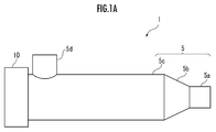
- FIG. 1A shows a side view of a first embodiment of the fluid sterilizer of the present invention.
- the fluid sterilizer 1 is a device that sterilizes a fluid flowing through a flow path by irradiating it with ultraviolet light.
- the fluid sterilizer 1 is used in a water purifier, a water heater, a water server, an industrial cooling water circulation device, and the like.
- the fluid sterilizer 1 has a flow path, and includes a housing 5 that serves as a fluid sterilizer and a light source module device 10 that includes an LED (Light Emitting Diode) as a light source.
- a light source module device 10 that includes an LED (Light Emitting Diode) as a light source.
- the housing 5 has a straight pipe shape with a diameter of 31.8 mm (inner diameter 29.4 mm) and a flow path (sterilization part) length of 100 mm, and the fluid to be sterilized flows in the long axis direction of the tubular body 5c. It has become like.
- the material of the tubular body 5c differs depending on the purpose of the fluid sterilizer 1, but here it is made of stainless steel.
- the fluid flows into the cylinder 5c from the inflow port 5a (inner diameter 12.7 mm) attached to one end of the cylinder 5c in the axial direction, and flows into the cylinder 5c, and the outflow port 5d (inner diameter 12) provided on the outer circumference of the cylinder 5c. It flows out from .7 mm).
- the flow rate is 0.5 to 5 (L / min).
- the housing 5 has a truncated cone portion 5b whose diameter increases in the direction of the tubular body 5c between the inflow port 5a and the tubular body 5c.
- the fluid flowing in from the inflow port 5a expands smoothly without abrupt expansion due to the presence of the truncated cone portion 5b. Therefore, the fluid does not stay in the boundary region after the flow path between the inflow port 5a and the tubular body 5c is expanded, and the generation of air bubbles can be suppressed.
- a straightening vane (not shown) may be provided near the boundary between the truncated cone portion 5b and the tubular body 5c.
- the fluid flowing in from the inflow port 5a passes through the straightening vane and reaches the flow path of the tubular body 5c.
- the straightening vane is a plate material made of metal or fluororesin, and has a plurality of holes penetrating in the axial direction of the tubular body 5c.
- the housing 5 shown in FIG. 1A is called an L-shaped pipe because of the arrangement of the inflow port 5a and the outflow port 5d.
- the housing 5 may be a so-called U-shaped pipe by providing the inflow port 5a on the outer periphery of the tubular body 5c.
- a detachable inflow device can be attached to the end of the tubular body 5c (on the side opposite to the light source module device 10) to form an L-shaped flow path.
- outlets 5d there was one outlet 5d, but a plurality of outlets may be provided on the outer circumference of the tubular body 5c. In this case, it is preferable to arrange the outlets at positions symmetrical with respect to the circumferential direction of the tubular body 5c. For example, when there are three outlets, the outlets may be arranged at intervals of 120 °.
- a light source module device 10 is attached to the end of the tubular body 5c on the opposite side of the inflow port 5a. The details of the light source module device 10 will be described later, but a light source, a substrate, a reflector, a quartz cap, and the like are housed therein.
- FIG. 1B is a view (rear view) of the fluid sterilizer 1 as viewed from the direction of the light source module device 10.
- the outlet 5d of the tubular body 5c projects upward.
- the second outlet projects at a position symmetrical with respect to the circumferential direction of the tubular body 5c, that is, downward.
- the holes 11a to 11d of the light source module device 10 are holes for screws for attaching a light source substrate, which will be described later.
- the hole portion 12 is a hole for a harness that connects the wiring of the board to an external power source.
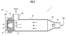
- FIG. 2 shows a cross-sectional view of II-II of the fluid sterilizer 1 of FIG. 1B.
- connection port 5f A female screw is formed in the connection port 5f on the light source module device 10 side of the tubular body 5c. Further, in the light source module device 10, a male screw is formed on the inner wall of the frame body 10a. Therefore, the light source module device 10 can be screwed into the connection port 5f. The relationship between the male screw and the female screw may be reversed, that is, the connection port 5f may be a male screw.
- the fluid that flows in from the inflow port 5a and reaches the flow path of the tubular body 5c proceeds in the direction of the outflow port 5d and flows out to the outside of the housing 5.
- the fluid is sterilized by being exposed to ultraviolet light emitted from the light source 3 (corresponding to the "first light source” of the present invention) in the light source module device 10 in the flow path.
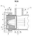
- FIG. 3A shows an enlarged view of the light source module device 10 of FIG.
- the ultraviolet light emitted from the light source 3 has a wavelength that has a bactericidal effect or a wavelength that decomposes a chemical substance. Its wavelength is, for example, in the range of 240 to 280 nm.
- the light source 3 is an ultraviolet LED, and as shown in the figure, one light source 3 is mounted on the front side of the substrate 4. It should be noted that a plurality of ultraviolet LEDs can be arranged side by side to serve as a light source.
- the substrate 4 is made of a metal such as copper or aluminum having excellent heat dissipation. Power is supplied to the light source 3 through the substrate 4. Further, the substrate 4 is in contact with the frame body 10a of the light source module device 10 on the rear surface side (the side opposite to the light emitting surface of the light source 3) and is fixed with screws (not shown).
- a reflector 8 is arranged so as to surround the light source 3.
- the reflector 8 is a reflector having a spheroidal surface or a rotating paraboloid.
- the ultraviolet light emitted from the light source 3 is reflected by the inner surface of the reflector 8 and distributed to an arbitrary location, and travels in the direction of the flow path of the tubular body 5c.
- the ultraviolet light is intensively irradiated to the portion of the flow path where the flow velocity of the fluid is high, so that the sterilization efficiency of the fluid can be improved.
- the ultraviolet light reflected by the reflector 8 passes through a quartz cap 9 (corresponding to the "first optical member” of the present invention) attached so as to cover the reflector 8.
- the quartz cap 9 is a member obtained by processing quartz glass having a refractive index larger than that of air to a substantially uniform thickness, and is composed of a cylindrical tubular portion 9a and a non-cylindrical tip portion 9b.
- the tip portion 9b has a planar shape or a curved surface shape connected to or extended to the tubular portion 9a.
- the boundary portion between the tubular portion 9a and the tip portion 9b is the boundary portion 9c, which is chamfered.
- the tubular body 5c may have a polygonal square tubular shape.
- both the tubular body 5c and the tubular portion 9a into a cylindrical shape, it is possible to suppress the generation of air bubbles inside and smooth the flow of the fluid.
- the tubular portion 9a can be easily fitted into the tubular body 5c with almost no gap.
- both the tubular body 5c and the tubular portion 9a have a square tubular shape, it is desirable that the ridgeline portion is chamfered.
- the tubular portion 9a is fitted into the inner wall of the tubular body 5c with almost no gap (with a gap of about 0.7 mm). Further, the tip portion 9b through which ultraviolet light passes is formed in a plane with respect to the open end surface of the reflector 8. As shown in the figure, the ultraviolet light is distributed to an arbitrary place by refraction when passing through the quartz cap 9 (tip portion 9b), and hits a portion in the flow path where the flow velocity of the fluid is high. Therefore, the fluid in the flow path is efficiently irradiated with ultraviolet light.
- the front side of the quartz cap 9 is filled with a fluid having a refractive index larger than that of air.
- the tip portion 9b of the quartz cap 9 may have a convex shape or other shape with respect to the open end surface of the reflector 8.
- the reflector 8 is not an essential configuration of the present invention, and the light distribution of ultraviolet light may be controlled by the shape of the tip portion 9b.
- the quartz cap 9 is arranged so that the boundary portion 9c is positioned so as to protrude from the end surface (inner wall) X on the side closer to the light source module device 10 of the outlet 5d.
- the quartz cap 9 may be arranged at a position where the boundary portion 9c coincides with the end face X.
- the fluid sterilizer 1 When the fluid sterilizer 1 is placed vertically (the light source module device 10 is above), there is a concern that bubbles will be generated in the gap and the fluid that has reached the vicinity of the outlet 5d will not be sufficiently irradiated with ultraviolet light.
- the quartz cap 9 by arranging the quartz cap 9 as described above, it is possible to suppress the generation of air bubbles near the outlet 5d and improve the fluid sterilization efficiency.
- the tubular portion 9a of the quartz cap 9 may be covered with a strip-shaped silicone sheet.
- a triangular groove 5f1 is formed on the inner wall of the end of the connection port 5f. Since the triangular groove 5f1 creates a space between the tubular portion 9a of the quartz cap 9 and the connection port 5f, the O-ring 6 (corresponding to the “seal member” of the present invention) is arranged. The sealing function of the O-ring 6 can prevent the fluid from entering the light source module device 10.
- the connection portion 5f2 in the drawing is a portion where a female screw of the connection port 5f is formed.
- the O-ring 6 is made of a fluorine-based material, but it may deteriorate when exposed to ultraviolet light. However, this position is outside the quartz cap 9 and also outside the reflector 8. Since the O-ring 6 is hardly irradiated with ultraviolet light, deterioration of the O-ring 6 can be prevented.
- the light source module device 10 is smaller than the conventional mechanism for adjusting the light distribution by superimposing lenses. Therefore, the fluid sterilizer 1 can reduce the size of the entire device. Further, since the quartz cap 9 is fitted on the outer periphery of the reflector 8 like a cap, there is an advantage that it can be easily replaced.
- the light source module device 10 may have a mode in which a plurality of light sources and reflectors are arranged on a single substrate and covered with a single quartz cap.
- the housing 5 is sealed by the O-ring 6 of the triangular groove 5f1.
- a slight gap was formed between the tubular portion 9a of the quartz cap 9 and the connection port 5f, and the fluid could enter.
- a triangular groove 5f3 is provided at a position corresponding to the boundary portion 9c of the quartz cap 9 in order to prevent fluid from entering the gap.
- the triangular groove 5f3 of the connection port 5f' is provided near the end surface X on the side of the tubular body 5c near the light source module device 10.
- the O-ring 6 is arranged in the space created by the triangular groove 5f3.
- the sealing function of the O-ring 6 can prevent the fluid from entering the light source module device 10.
- the quartz cap 9 is arranged so that the boundary portion 9c is positioned so as to protrude from the end face X of the outlet 5d.
- FIG. 4 shows a cross-sectional view of the fluid sterilizer 50 of the second embodiment. Since the side view and the rear view of the fluid sterilizer 50 are the same as those in FIGS. 1A and 1B, they are omitted. Further, in the following, the same reference numerals will be given to the same configurations as those in the first embodiment, and the description thereof will be omitted.
- the fluid that flows in from the inflow port 5a and reaches the flow path of the tubular body 5c proceeds in the direction of the outflow port 5d and flows out to the outside of the housing 5. At this time, the fluid is sterilized because it is exposed to the ultraviolet light emitted from the light source 3 in the light source module device 20 in the flow path.
- the quartz cap 19 of the light source module device 20 has a curved surface shape (round shape) whose tip portion protrudes toward the flow path side.
- FIG. 5 shows an enlarged view of the light source module device 20 of FIG.
- the light source module device 20 contains a light source 3, a substrate 4, a reflector 8, and a quartz cap 19 inside a frame body 20a.
- the arrangement of each member constituting the light source module device 20 is the same as that of the light source module device 10 (see FIG. 2B) described above.
- the ultraviolet light emitted from the light source 3 and reflected on the inner surface of the reflector 8 passes through the quartz cap 19 attached so as to cover the reflector 8.
- the quartz cap 19 is also quartz glass having a substantially uniform thickness.
- the ultraviolet light is refracted when passing through the quartz cap 19, and the ultraviolet light is distributed to an arbitrary place in the same manner as the above-mentioned quartz cap 9 (planar). Therefore, the quartz cap 19 is most suitable when the fluid in a certain region is intensively irradiated with ultraviolet light.
- the cylindrical tubular portion 19a is fitted into the inner wall of the tubular body 5c with almost no gap. Further, since the O-ring 6 is arranged between the quartz cap 19 and the connection port 5f (triangular groove 5f1), it is possible to prevent the fluid from entering the light source module device 20.
- the quartz cap 19 is arranged so that the boundary portion 19c is positioned so as to protrude from the end surface (inner wall) X on the side closer to the light source module device 20 of the outlet 5d.
- the fluid flowing through the tubular body 5c and hitting the tip portion 19b of the quartz cap 19 is guided in the direction of the outflow port 5d with almost no inflow into the gap between the tubular body 5c and the quartz cap 19.
- the quartz cap can be considered various other shapes, and each can be used properly according to the purpose of the device.
- the tip portion through which ultraviolet light passes is formed to be convex on both sides, and the tip portion is considered to be flat on one side (flow path side) and concave or convex on the other side (light source 3 side). Be done. Then, these can be used for different light distribution controls.
- a concave lens or a convex lens may be arranged in the space to control the light distribution.
- FIG. 6 shows a cross-sectional view of the fluid sterilizer 100 of the third embodiment.
- the fluid sterilizer 100 has a flow path, and includes a housing 15 that serves as a fluid sterilizer, a light source module device 10 that includes an LED as a light source, and a light source module device 30.
- the housing 15 is a so-called U-shaped pipe in which an inflow port 15a and an outflow port 15d are mounted on the outer circumference of the tubular body 15c.
- the fluid flows into the cylinder 15c from the inflow port 15a (inner diameter 12.7 mm) and flows out from the outflow port 15d (inner diameter 12.7 mm).
- the flow rate is 0.5 to 5 (L / min).
- the same light source module device 10 as in the first embodiment is attached to the connection port 15f, which is one end of the tubular body 15c (left side in the drawing).
- a light source module device 30 is attached to the connection port 15g, which is the other end of the tubular body 15c (on the right side in the drawing).
- a light source 33 Inside the light source module device 30, a light source 33, a substrate 34, a reflector 38, and a quartz cap 39 are housed. Immediately after the fluid flows into the housing 15 from the inflow port 15a, the fluid is irradiated with ultraviolet light by the light source 33 (corresponding to the "second light source” of the present invention) of the light source module device 30.
- the ultraviolet light emitted from the light source 33 is reflected by the inner surface of the reflector 38 to become parallel light, and travels in the direction of the flow path of the tubular body 15c.
- the fluid in the flow path is uniformly irradiated with ultraviolet light, so that the sterilization efficiency of the fluid can be improved.
- the ultraviolet light reflected by the reflector 38 passes through a cap-shaped quartz cap 39 (corresponding to the "second optical member" of the present invention) attached so as to cover the reflector 38.
- the quartz cap 39 is a member obtained by processing quartz glass having a refractive index larger than that of air to a substantially uniform thickness, similarly to the quartz cap 9 of the first embodiment.
- the quartz cap 39 is composed of a cylindrical tubular portion 39a and a non-cylindrical tip portion 39b, and the boundary portion between them is a chamfered boundary portion 39c.
- the tubular portion 39a is fitted into the inner wall of the tubular body 15c with almost no gap. Further, the tip portion 39b through which ultraviolet light passes is formed in a plane with respect to the open end surface of the reflector 38. Ultraviolet light is distributed to an arbitrary place by refraction when passing through the quartz cap 39 (tip portion 39b), and hits a portion in the flow path where the speed of the fluid is high. Therefore, the fluid in the flow path is efficiently irradiated with ultraviolet light.
- the quartz cap 39 is arranged so that the boundary portion 39c is positioned so as to protrude from the end surface (inner wall) Y on the side of the inflow port 15a near the light source module device 30. Therefore, the fluid flowing in from the inflow port 15a is guided in the direction of the cylinder body 15c with almost no inflow into the gap between the cylinder body 15c (connection port 15g) and the quartz cap 39. As a result, the fluid sterilizer 100 can suppress the generation of air bubbles in the vicinity of the inflow port 15a and improve the sterilization efficiency of the fluid.
- a space (triangular groove) is provided between the quartz cap 39 and the connection port 15g of the tubular body 15c, and the O-ring 6 is arranged (see FIG. 3A).
- the O-ring sealing function can prevent the fluid from entering the light source module device 30.
- the fluid that has passed through the tubular body 15c is irradiated with ultraviolet light by the light source 3 of the light source module device 10 near the outlet 15d. Thereby, the sterilization efficiency can be further improved.
- the above-mentioned light source module device 20 and the like may be adopted depending on the purpose. Further, different light source module devices may be adopted for the light source module device 10 and the light source module device 30.
- the above embodiment is only an example, and can be appropriately changed according to the intended use. Since the flow rate of the cylinder of the fluid sterilizer differs depending on the application, the size and shape can be changed.
- the light source module device of the present invention is not limited to a running water reactor attached to a part of a water channel.
- the fluid in the container can be sterilized by irradiating it with ultraviolet light.
- the ultraviolet light may be irradiated to the fluid from the side surface side of the container, or may be irradiated from the upper surface side. In addition to this, it can also be used for surface sterilization, water stains in bathrooms, and sterilization as a measure against mold.
- the cross-sectional shape of the cylinder is not limited to a circular shape or an oval shape, and may be a polygonal shape.
- three or more light source module devices may be attached to the end of the housing.
- the number of light sources in one light source module device can be changed as appropriate, and can be arranged in a matrix according to the cross-sectional shape of the housing.
- the direction in which the fluid flows is generally opposite to the irradiation direction of ultraviolet light, but even if it matches the irradiation direction. Good.
- the number and direction of the inflow port and the outflow port, the number of ultraviolet LEDs, and the like can be changed as appropriate.
- the inner wall of the cylinder of the fluid sterilizer is made of polyvinyl chloride
- it may be coated with an ultraviolet light reflecting material or an ultraviolet light absorbing material in order to prevent the polyvinyl chloride from being deteriorated by ultraviolet light.
- an ultraviolet light reflecting material a fluorine-based resin such as PTFE, aluminum, or the like can be used.
- the ultraviolet light absorbing material stainless steel or the like can be used.
Landscapes
- Health & Medical Sciences (AREA)
- Life Sciences & Earth Sciences (AREA)
- Epidemiology (AREA)
- Veterinary Medicine (AREA)
- Public Health (AREA)
- General Health & Medical Sciences (AREA)
- Animal Behavior & Ethology (AREA)
- Engineering & Computer Science (AREA)
- Organic Chemistry (AREA)
- Chemical & Material Sciences (AREA)
- Water Supply & Treatment (AREA)
- Environmental & Geological Engineering (AREA)
- Hydrology & Water Resources (AREA)
- Toxicology (AREA)
- Apparatus For Disinfection Or Sterilisation (AREA)
- Physical Water Treatments (AREA)
Abstract
流体殺菌装置1は、流体が軸方向に流れる流路を有する筐体5の筒体5cと、流体が筒体5cに流入する流入口5aと、筒体5cの外周上に設けられた流出口5bと、流入口5aとは反対側の端部に設けられた光源3と、筒部9aと先端部9bとからなり、紫外光を透過、集光又は発散する石英キャップ9を備えている。石英キャップ9は、筒部9aが筒体5cの内壁に嵌合しており、境界部9cが、流出口5bの光源3に近い側の端面Xに一致する位置、又は端面Xよりも突出した位置に配置されている。
Description
本発明は、流路を流れる流体を紫外光により殺菌する流体殺菌装置に関する。
近年、紫外線の殺菌作用が、食品庫の殺菌灯や医療用装置に利用されている。また、流路を流れる流体に対して、紫外LEDにより紫外光を照射して流体を殺菌し、洗浄用水等に用いる装置もよく知られている。
例えば、下記の特許文献1の流体殺菌モジュールは、流水が流通する内部空間を有する流路管と、流路管の一端部の側から内部空間に突出し、内部空間に向けて紫外線を照射可能とした光源とを備えている。
具体的には、前記光源は、発生する熱を放熱する放熱部材を備え、放熱部材の一端部が、第一流入出口よりも流路管の他端部の側に飛び出して配置されている。また、前記放熱部材は、光源が取り付けられる光源取付部と、光源で発生する熱を放熱する放熱部とを兼ねる柱状部を有している(特許文献1/段落0012,0016,図1)。
しかしながら、特許文献1の流体殺菌モジュールは、配置する向きや流水の方向によっては、柱状部とモジュール内壁との間の内部空間に気泡が発生するため、紫外線による殺菌効率が低下するおそれがある。
本発明は、このような事情に鑑みてなされたものであり、紫外光の利用効率を高め、殺菌効果を向上させることができる流体殺菌装置を提供することを目的とする。
本発明の流体殺菌装置は、殺菌対象の流体が軸方向に流れる流路を有する筒体と、前記流体が前記筒体に流入する流入口と、前記筒体の外周上に設けられ、前記流体が流出する流出口と、前記筒体の前記流入口とは反対側の端部に設けられた基板に実装され、前記流路に向けて紫外光を出射する発光素子を有する第1の光源と、筒部と先端部とからなり、前記第1の光源を収容し、前記紫外光を透過、集光又は発散する第1の光学部材とを備え、前記筒部は前記筒体の内壁に嵌入し、前記筒部と前記先端部との境界部が前記流出口の前記第1の光源に近い側の端面に一致する位置にあるか、又は前記近い側の端面よりも突出した位置にあることを特徴とする。
本発明の流体殺菌装置では、第1の光源から出射された紫外光が、当該第1の光源を収容する第1の光学部材で透過、集光又は発散される。そして、紫外光が流路を通過する流体を照射することで殺菌が進む。
本装置は、配置の向きによって内部に気泡が生じて紫外光の照射効率を低下させないように、第1の光学部材の筒部は筒体の内壁に嵌合させ、ほとんど隙間がない状態とする。また、第1の光学部材の筒部と先端部との境界部を、流出口の第1の光源に近い側の端面に一致する位置、又はこれよりも突出した位置となるようにして、先端部に当たった流体を流出口の方向に導く。これにより、本装置は、気泡の発生を抑えつつ、殺菌効果を向上させることができる。
本発明の流体殺菌装置において、前記筒体と前記第1の光学部材の前記筒部とは、円筒形状であることが好ましい。
本発明では、流体殺菌装置の筒体と第1の光学部材の筒部を、ともに円筒形状とする。これにより、本装置は、内部での気泡の発生を抑制し、流体の流れを円滑にすることができ、また、筒体の内径と筒部の外径を合わせることで、容易に当該筒部を当該筒体に隙間なく嵌入させることができる。
また、本発明の流体殺菌装置において、前記第1の光学部材の前記先端部は、平面形状を有していることが好ましい。
本発明では、第1の光学部材の先端部を平面形状とする。第1の光源から出射された紫外光は、当該先端部を透過し、集光又は発散する。これにより、本装置は、流路内の流体に紫外光が満遍なく照射されるようにすることができる。
また、本発明の流体殺菌装置において、前記境界部は面取り加工されていることが好ましい。
第1の光学部材の先端部が平面形状である場合、面取り加工された境界部を、流出口の第1の光源に近い側の端面に一致する位置、又はこれよりも突出した位置とする。これにより、本装置は、気泡の発生を抑えつつ、流体を流出口の方向に導くことができる。
本発明の流体殺菌装置において、前記第1の光学部材の前記先端部は、前記流路側に突出した曲面形状を有していることが好ましい。
第1の光学部材の先端部は、曲面形状(丸形状)としてもよい。この場合、当該先端部は、第1の光源から出射された紫外光を流路の特定部分に集光させることができる。すなわち、本装置は、目的に応じて光学部材の先端部を変更して、所望の配光を得ることができる。
また、本発明の流体殺菌装置において、前記筒体は、前記第1の光源側の端部内壁に切欠部を有し、前記第1の光学部材は、前記切欠部に収容されたシール部材を介して固定されていることが好ましい。
筒体が端部内壁に切欠部を有していることで、本装置は、当該切欠部にシール部材を設けることができる。本装置は、当該シール部材で第1の光学部材を固定することができ、さらに流体が第1の光源側に浸入することを防止することができる。
また、本発明の流体殺菌装置において、前記筒体は、当該筒体の前記境界部に対応する位置に切欠部を有し、前記第1の光学部材は、前記切欠部に収容されたシール部材を介して固定されていることが好ましい。
本発明の筒体は、第1の光学部材の境界部に対応する位置に切欠部を有していてもよい。この場合も当該切欠部にシール部材を設けることができるので、本装置は、筒体と第1の光学部材(筒部)との間に僅かな隙間があっても、流体が浸入しないようにすることができる。
また、本発明の流体殺菌装置において、前記第1の光学部材の内部に、前記第1の光源を囲むように前記基板上に配置され、前記紫外光を内面で反射して前記流路の方向に導くリフレクタを有していることが好ましい。
この構成によれば、第1の光源から出射された紫外光がリフレクタの内面で反射される。このため、本装置は、紫外光を任意の場所に配光し、流路内で流速の速い部分に集中的に紫外光を照射することができる。これにより、本装置は、流体の殺菌効率をより高めることができる。
また、本発明の流体殺菌装置において、前記筒体の周方向に対称な位置に、前記流出口が複数設けられていることが好ましい。
本発明では、筒体の周方向に対称な位置に流出口を複数設ける。これにより、本装置は、殺菌した流体を流出口付近で滞留することなく、排出することができる。
また、本発明の流体殺菌装置において、前記流入口は、前記筒体との間に、当該筒体の方向に向かって径が拡大する円錐台部を有していることが好ましい。
本装置は、流体の流入口側に円錐台部を設けることで、流体を、ある程度滑らかに筒体内に流入させることができる。そして、本装置は、流入口側での気泡の発生を抑えることができる。
また、本発明の流体殺菌装置において、前記流入口は、前記筒体の外周上に設けられていることが好ましい。
流体の流入口を筒体の外周に設けることで、本装置は、いわゆるU字型の流路を有する装置として、目的に応じて使用することができる。
また、本発明の流体殺菌装置において、前記筒体の前記流入口に近い側の端部に設けられた基板に実装され、前記流路に向けて紫外光を出射する発光素子を有する第2の光源と、筒部と先端部とからなり、前記第2の光源を収容し、前記紫外光を透過、集光又は発散する第2の光学部材と、を備え、前記筒部は前記筒体の内壁に嵌入し、前記筒部と前記先端部との境界部が前記流入口の前記第2の光源に近い側の端面に一致する位置にあるか、又は前記近い側の端面よりも突出していることが好ましい。
本装置は、筒体の外周上に流入口を設けたとき、流入口に近い側に端部に第2の光源を設けることができる。また、本装置は、流入口側から第2の光源の紫外光により流体を照射し、流出口側から第1の光源の紫外光により流体を照射するため、殺菌効率が向上する。
また、第2の光源に対して設けられる第2の光学部材についても、筒部が筒体の内壁に嵌合し、境界部を流入口の第2の光源に近い側の端面に一致する位置、又はこれよりも突出した位置になるようにする。これにより、本装置は、流入口側での気泡の発生を抑えることができる。
以下、本発明の流体殺菌装置の実施形態について説明する。
[第1実施形態]
まず、図1Aに、本発明の流体殺菌装置の第1実施形態の側面図を示す。流体殺菌装置1は、流路を流れる流体に対して紫外光を照射して殺菌する装置である。流体殺菌装置1は、浄水器、給湯器、ウォーターサーバ、工業用冷却水循環装置等に利用される。
まず、図1Aに、本発明の流体殺菌装置の第1実施形態の側面図を示す。流体殺菌装置1は、流路を流れる流体に対して紫外光を照射して殺菌する装置である。流体殺菌装置1は、浄水器、給湯器、ウォーターサーバ、工業用冷却水循環装置等に利用される。
流体殺菌装置1は流路を有し、流体の殺菌部となる筐体5と、光源としてのLED(Light Emitting Diode)を含む光源モジュール装置10とを備える。
筐体5は、直径が31.8mm(内径29.4mm)、流路(殺菌部)の長さが100mmの直管形状を有し、殺菌対象の流体が筒体5cの長軸方向に流れるようになっている。筒体5cの材料は流体殺菌装置1の目的により異なるが、ここではステンレス製である。流体は、筒体5cの軸方向の一端部に取り付けられた流入口5a(内径12.7mm)から筒体5cに流入して、筒体5cの外周上に設けられた流出口5d(内径12.7mm)から流出する。流量は、0.5~5(L/min)である。
また、筐体5は、流入口5aと筒体5cの間に、筒体5cの方向に向かって径が拡大する円錐台部5bを有している。流入口5aから流入した流体は、円錐台部5bがあることで急激に拡大することなく、滑らかに拡大する。このため、流入口5aから筒体5cの間の流路が拡大された後の境界領域に流体が滞留せず、気泡の発生を抑えることができる。
円錐台部5bと筒体5cの境界部付近に、整流板(図示省略)を設けてもよい。この場合、流入口5aから流入した流体は、整流板を通過して筒体5cの流路に到達する。整流板は金属製又はフッ素樹脂製の板材であり、筒体5cの軸方向に貫通する複数の孔を有している。整流板を通過することにより、流体は、筒体5cの流路に流入する際に流速が平均化される。従って、紫外光が流体に万遍なく照射されるようになり、殺菌性能が向上する。
図1Aに示す筐体5は、流入口5a及び流出口5dの配置からL字管と呼ばれる。筐体5は、流入口5aを筒体5cの外周上に設けて、いわゆるU字管としてもよい。また、筒体5cの端部(光源モジュール装置10と反対側)に着脱可能な流入装置を取り付けて、L字型の流路とすることもできる。
図1Aの例では、流出口5dが1つであったが、筒体5cの外周上に複数の流出口を設けてもよい。この場合、筒体5cの周方向に対称な位置に流出口を配置することが好ましい。例えば、流出口が3つの場合は、120°間隔で流出口を配置すればよい。
筒体5cの流入口5aと反対側の端部には、光源モジュール装置10が取り付けられている。光源モジュール装置10の詳細は後述するが、その内部には、光源、基板、リフレクタ、石英キャップ等が収められている。
図1Bは、流体殺菌装置1を光源モジュール装置10の方向から見た図(背面図)である。ここでは、筒体5cの流出口5dが上方向に突出している。流出口が2つの場合は、筒体5cの周方向に対称な位置、すなわち下方向に第2の流出口が突出することになる。
光源モジュール装置10(背面側)の孔部11a~11dは、後述する光源用基板を取り付けるビス用の孔である。また、孔部12は、当該基板の配線を外部の電源に接続するハーネス用の孔である。なお、当該基板の裏面側(光源の発光面がない側)に金属製のヒートシンク(図示省略)を設けた場合、当該基板の熱を放熱することができる。
次に、図2に、図1Bの流体殺菌装置1のII-II断面図を示す。
筒体5cの光源モジュール装置10側にある接続ポート5fには、雌ネジが形成されている。また、光源モジュール装置10は、枠体10aの内壁に雄ネジが形成されている。このため、光源モジュール装置10を接続ポート5fに螺合させることができる。なお、雄ネジ、雌ネジの関係は逆、すなわち、接続ポート5fが雄ネジとなっていてもよい。
流入口5aから流入し、筒体5cの流路に到達した流体は、流出口5dの方向に進み、筐体5の外部に流出する。このとき、流路内で光源モジュール装置10内の光源3(本発明の「第1の光源」に相当)から出射された紫外光に晒されて、流体が殺菌される。
次に、図3Aに、図2の光源モジュール装置10の拡大図を示す。
光源3から出射される紫外光は、殺菌効果を有する波長又は化学物質を分解する波長を有している。その波長は、例えば、240~280nmの範囲である。光源3は紫外LEDであり、図示するように、基板4の前面側に1つ実装されている。なお、紫外LEDを複数並べて光源とすることもできる。
基板4は、放熱性に優れた銅、アルミニウム等の金属製のものが望ましい。基板4を通して、光源3に給電が行われる。また、基板4は、その後面側(光源3の発光面と反対側)で光源モジュール装置10の枠体10aに当接して、ネジ(図示省略)で固定されている。
また、基板4の前面側には、光源3を囲むようにリフレクタ8が配設されている。リフレクタ8は、回転楕円面又は回転放物面の反射鏡である。光源3から出射された紫外光は、リフレクタ8の内面で反射して任意の場所に配光され、筒体5cの流路の方向に進む。これにより、流路内の流体の流速が速い部分に集中的に紫外光が照射されるため、流体の殺菌効率を高めることができる。
リフレクタ8で反射された紫外光は、リフレクタ8を覆うように取り付けられた石英キャップ9(本発明の「第1の光学部材」に相当)を通過する。石英キャップ9は、空気よりも屈折率の大きい石英ガラスを略均一の厚みに加工した部材であり、円筒形状の筒部9aと非円筒形状の先端部9bとで構成されている。先端部9bは、筒部9aに接続された、又は延在した平面形状又は曲面形状を有する。なお、筒部9aと先端部9bとの境界部分が境界部9cであり、面取り加工されている。
筒体5cは、多角形の角筒形状であってもよい。しかしながら、本実施形態のように、筒体5cと筒部9aをともに円筒形状とすることで、内部での気泡の発生を抑制し、流体の流れを円滑にすることができる。さらに、筒体5cの内径と筒部9aの外径を一致させることで、容易に筒部9aを筒体5cにほぼ隙間なく嵌入させることができる。筒体5cと筒部9aとをともに角筒形状とする場合には、稜線部が面取り加工されていることが望ましい。
筒部9aは、筒体5cの内壁にほぼ隙間なく(0.7mm程度の隙間はある)嵌入している。また、紫外光が通過する先端部9bは、リフレクタ8の開口端面に対して平面状に形成されている。図示するように、紫外光は、石英キャップ9(先端部9b)を通過する際に屈折により任意の場所に配光され、流路内の流体の流速が速い部分に当たる。このため、流路内の流体に効率良く紫外光が照射される。
流体殺菌装置1の使用時には、石英キャップ9の前面側は、空気よりも屈折率の大きい流体で満たされている。詳細は後述するが、石英キャップ9の先端部9bは、リフレクタ8の開口端面に対して、凸状又はその他の形状であってもよい。なお、リフレクタ8は本発明の必須の構成ではなく、先端部9bの形状により、紫外光の配光を制御してもよい。
また、石英キャップ9は、境界部9cが流出口5dの光源モジュール装置10に近い側の端面(内壁)Xよりも突出した位置となるように配置されている。これにより、筒体5cを流通して石英キャップ9の先端部9bに当たった流体は、筒体5cと石英キャップ9との隙間にほとんど流入することなく、流出口5dの方向に導かれる。石英キャップ9は、境界部9cが端面Xと一致する位置に配置してもよい。
流体殺菌装置1を縦置き(光源モジュール装置10が上方)した場合、当該隙間に気泡が発生して、流出口5d付近に到達した流体に対して紫外光が十分照射されないという懸念がある。しかしながら、流体殺菌装置1は、上記のように石英キャップ9を配置することで、流出口5d付近の気泡の発生を抑え、流体の殺菌効率を向上させることができる。なお、当該隙間をさらに小さくするため、石英キャップ9の筒部9aを帯状のシリコーンシートで被覆してもよい。
また、図示するように、接続ポート5fの端部内壁には、三角溝5f1が形成されている。三角溝5f1により、石英キャップ9の筒部9aと接続ポート5fとの間に空間が生じるので、Oリング6(本発明の「シール部材」に相当)を配置する。そして、Oリング6の封止機能により、光源モジュール装置10への流体の浸入を防止することができる。なお、図中の接続部5f2は、接続ポート5fの雌ネジが形成された部分である。
Oリング6はフッ素系材料で形成されるが、紫外光に晒されて劣化することがある。しかしながら、この位置は石英キャップ9の外側であり、リフレクタ8の外側でもある。Oリング6にはほとんど紫外光が照射されないので、Oリング6の劣化を防止することができる。
このように、光源モジュール装置10は、従来のレンズを重ねて配光を調整する機構と比較して小型である。このため、流体殺菌装置1は、装置全体を小型化することができる。また、石英キャップ9は、リフレクタ8の外周にキャップのように嵌め込まれるため、交換が容易という利点もある。なお、光源モジュール装置10は、単一基板上に複数の光源とリフレクタとを配置し、単一の石英キャップで覆われる態様であってもよい。
次に、図3Bを参照して、上述の筐体5の変更形態(筐体5’)を説明する。
図3Aに示した筐体5では、三角溝5f1のOリング6によって封止される。しかしながら、石英キャップ9の筒部9aと接続ポート5fとの間に僅かな隙間が生じて、流体が浸入可能であった。この点、変更形態の筐体5’(接続ポート5f’)では、当該隙間への流体の浸入を防止するため、石英キャップ9の境界部9cに対応する位置に三角溝5f3を設けている。
図示するように、接続ポート5f’の三角溝5f3は、筒体5cの光源モジュール装置10に近い側の端面X付近に設けられている。そして、この三角溝5f3により生じた空間にOリング6を配設する。この場合も、Oリング6の封止機能により、光源モジュール装置10への流体の浸入を防止することができる。もちろん、石英キャップ9は、境界部9cが流出口5dの端面Xよりも突出した位置となるように配置することが好ましい。
[第2実施形態]
次に、図4、図5を参照して、本発明の流体殺菌装置の第2実施形態を説明する。
次に、図4、図5を参照して、本発明の流体殺菌装置の第2実施形態を説明する。
図4は、第2実施形態の流体殺菌装置50の断面図を示している。なお、流体殺菌装置50の側面図及び背面図は図1A、図1Bと同じであるため、省略する。また、以下では、第1実施形態と同じ構成については同じ符号を付し、説明を省略する。
図示するように、筒体5cの光源モジュール装置20側の端部の接続ポート5fには、雌ネジが形成されている。光源モジュール装置20は、枠体20aの内壁に雄ネジが形成されているため、光源モジュール装置20を接続ポート5fに螺合させることができる。
流入口5aから流入し、筒体5cの流路に到達した流体は、流出口5dの方向に進み、筐体5の外部に流出する。このとき、流路内で光源モジュール装置20内の光源3から出射された紫外光に晒されるので、流体が殺菌される。光源モジュール装置20の石英キャップ19は、先端部が流路側に突出した曲面形状(丸形状)を有する。
次に、図5に、図4の光源モジュール装置20の拡大図を示す。
光源モジュール装置20は、枠体20aの内部に光源3、基板4、リフレクタ8及び石英キャップ19が収められている。光源モジュール装置20を構成する各部材の配置は、上述の光源モジュール装置10(図2B参照)と同じである。
光源3から出射され、リフレクタ8の内面で反射された紫外光は、リフレクタ8を覆うように取り付けられた石英キャップ19を通過する。石英キャップ19も略均一の厚みの石英ガラスである。紫外光は石英キャップ19を通過する際に屈折し、上述の石英キャップ9(平面状)と同様に紫外光を任意の場所に配光する。従って、石英キャップ19は、ある領域の流体に集中的に紫外光を照射するような場合に最適である。
ここでも、円筒形状の筒部19aは、筒体5cの内壁にほぼ隙間なく嵌入している。また、石英キャップ19と接続ポート5f(三角溝5f1)との間にOリング6を配設するため、光源モジュール装置20への流体の浸入を防止することができる。
また、石英キャップ19は、境界部19cが流出口5dの光源モジュール装置20に近い側の端面(内壁)Xよりも突出した位置となるように配置されている。これにより、筒体5cを流通して石英キャップ19の先端部19bに当たった流体は、筒体5cと石英キャップ19との隙間にほとんど流入することなく、流出口5dの方向に導かれる。
石英キャップ19は、境界部19cが端面Xと一致する位置に配置してもよい。この位置に石英キャップ19を配置することで、本装置は、流出口5d付近の気泡の発生を抑えて、流体の殺菌効率を向上させることができる。
石英キャップは、この他にも様々な形状が考えられ、それぞれ装置の目的に応じて使い分けることができる。例えば、紫外光が通過する先端部が両面凸状に形成されているもの、先端部を一方の側(流路側)が平面状で他方の側(光源3側)凹状又は凸状のものが考えられる。そして、これらは、それぞれ異なる配光制御に用いることができる。石英キャップ19の場合、リフレクタ8(内面)との間にスペースが生じるため、当該スペースに凹レンズ又は凸レンズを配設して、配光を制御してもよい。
[第3実施形態]
最後に、図6を参照して、本発明の流体殺菌装置の第3実施形態を説明する。
最後に、図6を参照して、本発明の流体殺菌装置の第3実施形態を説明する。
図6は、第3実施形態の流体殺菌装置100の断面図を示している。流体殺菌装置100は流路を有し、流体の殺菌部となる筐体15と、光源としてのLEDを含む光源モジュール装置10及び光源モジュール装置30とを備える。
筐体15は、筒体15cの外周上に流入口15a及び流出口15dを取り付けた、いわゆるU字管である。流体は流入口15a(内径12.7mm)から筒体15cに流入して、流出口15d(内径12.7mm)から流出する。その流量は、0.5~5(L/min)である。
筒体15cの一端部(図の左側)である接続ポート15fには、第1実施形態と同じ光源モジュール装置10が取り付けられている。また、筒体15cの他端部(図の右側)である接続ポート15gには、光源モジュール装置30が取り付けられている。
光源モジュール装置30の内部には、光源33、基板34、リフレクタ38及び石英キャップ39が収められている。流体は、流入口15aから筐体15に流入した直後に、光源モジュール装置30の光源33(本発明の「第2の光源」に相当)により紫外光が照射される。
光源33から出射された紫外光は、リフレクタ38の内面で反射して平行光となり、筒体15cの流路の方向に進む。これにより、流路内の流体に均一に紫外光が照射されるため、流体の殺菌効率を高めることができる。また、リフレクタ38で反射された紫外光は、リフレクタ38を覆うように取り付けられたキャップ状の石英キャップ39(本発明の「第2の光学部材」に相当)を通過する。
石英キャップ39は、第1実施形態の石英キャップ9と同様に、空気よりも屈折率の大きい石英ガラスを略均一の厚みに加工した部材である。なお、石英キャップ39は、円筒形状の筒部39aと非円筒形状の先端部39bとで構成され、それらの境界部分が面取り加工された境界部39cである。
筒部39aは、筒体15cの内壁にほぼ隙間なく嵌入している。また、紫外光が通過する先端部39bは、リフレクタ38の開口端面に対して平面状に形成されている。紫外光は、石英キャップ39(先端部39b)を通過する際に屈折により任意の場所に配光され、流路内の流体の速度が速い部分に当たる。このため、流路内の流体に効率良く紫外光が照射される。
また、石英キャップ39は、境界部39cが流入口15aの光源モジュール装置30に近い側の端面(内壁)Yよりも突出した位置となるように配置されている。従って、流入口15aから流入した流体は、筒体15c(接続ポート15g)と石英キャップ39との隙間にほとんど流入することなく、筒体15cの方向に導かれる。これにより、流体殺菌装置100は、流入口15a付近での気泡の発生を抑えて、流体の殺菌効率を向上させることができる。
また、石英キャップ39と筒体15cの接続ポート15gとの間に空間(三角溝)が設け、Oリング6を配設する(図3A参照)。そして、Oリングの封止機能により、光源モジュール装置30への流体の浸入を防止することができる。
さらに、流体殺菌装置100では、筒体15cを通過した流体が、流出口15d付近で光源モジュール装置10の光源3により紫外光が流体に照射される。これにより、殺菌効率をさらに向上させることができる。
光源モジュール装置10,30は、目的に応じて上述の光源モジュール装置20等を採用してもよい。また、光源モジュール装置10と光源モジュール装置30とで、異なる光源モジュール装置を採用してもよい。
上述の実施形態は一例に過ぎず、用途に応じて適宜変更することができる。流体殺菌装置の筒体は、用途により流量が異なるため、サイズや形状を変更することができる。特に、本発明の光源モジュール装置は、水路の一部に取り付ける流水リアクタに限られるものではない。
例えば、光源モジュール装置を専用の接続ポートを有するサーバや貯水タンクに取り付けることで、容器内の流体に対して紫外光を照射し、殺菌することができる。紫外光は、容器の側面側から流体に照射してもよいし、上面側から照射してもよい。この他にも、表面殺菌や風呂場の水垢、カビ対策としての殺菌にも利用することができる。
筒体の断面形状は、円形状、オーバル形状に限られず、多角形状としてもよい。筐体の断面積に応じて、例えば、3個以上の光源モジュール装置を筐体の端部に取り付けてもよい。1つの光源モジュール装置内の光源の数も適宜変更することができ、筐体の断面形状に応じてマトリクス状に配置すること等が可能である。
流体殺菌装置1のように、流路の片側に光源が配設される形態では、流体が流れる方向は、一般的に紫外光の照射方向と逆向きであるが、照射方向と一致させてもよい。流入口、流出口の数や方向、紫外LEDの数等も適宜変更可能である。
流体殺菌装置の筒体の内壁がポリ塩化ビニルで構成される場合、ポリ塩化ビニルの紫外光による劣化を防止するため、紫外光反射材料や紫外光吸収材料でコーティングするようにしてもよい。紫外光反射材料としては、PTFE等のフッ素系樹脂、アルミニウム等を用いることができる。また、紫外光吸収材料としては、ステンレス鋼等を用いることができる。
1,50,100…流体殺菌装置、3,33…光源、4,34…基板、5,5’、15…筐体、5a,15a…流入口、5b…円錐台部、5c,15c…筒体、5d,15d…流出口、5f,5f’15f,15g…接続ポート、6,36…Oリング、8,38…リフレクタ、9,19,39…石英キャップ、9a,19a,39a…筒部、9b,19b,39b…先端部、9c,19c,39c…境界部、10,20,30…光源モジュール装置、10a,20a…枠体、11a~11d…孔部(ネジ用)、12…孔部(ハーネス用)。
Claims (12)
- 殺菌対象の流体が軸方向に流れる流路を有する筒体と、
前記流体が前記筒体に流入する流入口と、
前記筒体の外周上に設けられ、前記流体が流出する流出口と、
前記筒体の前記流入口とは反対側の端部に設けられた基板に実装され、前記流路に向けて紫外光を出射する発光素子を有する第1の光源と、
筒部と先端部とからなり、前記第1の光源を収容し、前記紫外光を透過、集光又は発散する第1の光学部材とを備え、
前記筒部は前記筒体の内壁に嵌入し、前記筒部と前記先端部との境界部が前記流出口の前記第1の光源に近い側の端面に一致する位置にあるか、又は前記近い側の端面よりも突出した位置にある、流体殺菌装置。 - 前記筒体と前記第1の光学部材の前記筒部とは、円筒形状である、請求項1に記載の流体殺菌装置。
- 前記第1の光学部材の前記先端部は、平面形状を有している、請求項1又は2に記載の流体殺菌装置。
- 前記境界部は面取り加工されている、請求項3に記載の流体殺菌装置。
- 前記第1の光学部材の前記先端部は、前記流路側に突出した曲面形状を有している、請求項1又は2に記載の流体殺菌装置。
- 前記筒体は、前記第1の光源側の端部内壁に切欠部を有し、
前記第1の光学部材は、前記切欠部に収容されたシール部材を介して固定されている、請求項1~5の何れか1項に記載の流体殺菌装置。 - 前記筒体は、当該筒体の前記境界部に対応する位置に切欠部を有し、
前記第1の光学部材は、前記切欠部に収容されたシール部材を介して固定されている、請求項1~5の何れか1項に記載の流体殺菌装置。 - 前記第1の光学部材の内部に、前記第1の光源を囲むように前記基板上に配置され、前記紫外光を内面で反射して前記流路の方向に導くリフレクタを有している、請求項1~7の何れか1項に記載の流体殺菌装置。
- 前記筒体の周方向に対称な位置に、前記流出口が複数設けられている、請求項1~8の何れか1項に記載の流体殺菌装置。
- 前記流入口は、前記筒体との間に、当該筒体の方向に向かって径が拡大する円錐台部を有している、請求項1~9の何れか1項に記載の流体殺菌装置。
- 前記流入口は、前記筒体の外周上に設けられている、請求項1~9の何れか1項に記載の流体殺菌装置。
- 前記筒体の前記流入口に近い側の端部に設けられた基板に実装され、前記流路に向けて紫外光を出射する発光素子を有する第2の光源と、
筒部と先端部とからなり、前記第2の光源を収容し、前記紫外光を透過、集光又は発散する第2の光学部材と、を備え、
前記筒部は前記筒体の内壁に嵌入し、前記筒部と前記先端部との境界部が前記流入口の前記第2の光源に近い側の端面に一致する位置にあるか、又は前記近い側の端面よりも突出している、請求項11に記載の流体殺菌装置。
Priority Applications (3)
| Application Number | Priority Date | Filing Date | Title |
|---|---|---|---|
| EP20881085.3A EP4052731A4 (en) | 2019-10-30 | 2020-10-14 | Fluid sterilization device |
| US17/766,075 US20220362419A1 (en) | 2019-10-30 | 2020-10-14 | Fluid sterilization device |
| CN202080069406.9A CN114514204A (zh) | 2019-10-30 | 2020-10-14 | 流体杀菌装置 |
Applications Claiming Priority (2)
| Application Number | Priority Date | Filing Date | Title |
|---|---|---|---|
| JP2019-197353 | 2019-10-30 | ||
| JP2019197353A JP7398243B2 (ja) | 2019-10-30 | 2019-10-30 | 流体殺菌装置 |
Publications (1)
| Publication Number | Publication Date |
|---|---|
| WO2021085143A1 true WO2021085143A1 (ja) | 2021-05-06 |
Family
ID=75714115
Family Applications (1)
| Application Number | Title | Priority Date | Filing Date |
|---|---|---|---|
| PCT/JP2020/038823 Ceased WO2021085143A1 (ja) | 2019-10-30 | 2020-10-14 | 流体殺菌装置 |
Country Status (5)
| Country | Link |
|---|---|
| US (1) | US20220362419A1 (ja) |
| EP (1) | EP4052731A4 (ja) |
| JP (1) | JP7398243B2 (ja) |
| CN (1) | CN114514204A (ja) |
| WO (1) | WO2021085143A1 (ja) |
Cited By (2)
| Publication number | Priority date | Publication date | Assignee | Title |
|---|---|---|---|---|
| EP4091985A1 (en) * | 2021-05-17 | 2022-11-23 | Stanley Electric Co., Ltd. | Beverage supply device |
| US20240150202A1 (en) * | 2021-03-19 | 2024-05-09 | Stanley Electric Co., Ltd. | Fluid sterilization device |
Families Citing this family (5)
| Publication number | Priority date | Publication date | Assignee | Title |
|---|---|---|---|---|
| CA3186106A1 (en) * | 2020-07-17 | 2022-01-20 | David Allan Prystupa | Apparatus for reflecting an incident ray of electromagnetic radiation |
| AU2022200240A1 (en) * | 2021-09-07 | 2023-03-23 | Shenzhen Yitoa Intelligent Industrial Co., Ltd | Sterilization device, air filter, and filtration system |
| JP2023113016A (ja) * | 2022-02-02 | 2023-08-15 | スタンレー電気株式会社 | 流体殺菌装置 |
| CN116854185A (zh) * | 2023-08-30 | 2023-10-10 | 佛山市锐诚云智能科技有限公司 | 净水系统的紫外线光源控制方法、装置及驱动电源 |
| JP2025171283A (ja) * | 2024-05-09 | 2025-11-20 | 三浦工業株式会社 | 流体殺菌装置 |
Citations (8)
| Publication number | Priority date | Publication date | Assignee | Title |
|---|---|---|---|---|
| JPH10277546A (ja) * | 1997-04-09 | 1998-10-20 | Nanbu Kasei Kk | 浴槽水の殺菌方法及び浴槽水循環温浴器 |
| JP2011016074A (ja) * | 2009-07-09 | 2011-01-27 | U-Vix Corp | 紫外線殺菌浄水装置とそれに使用する紫外線ledユニット |
| JP2018030077A (ja) * | 2016-08-23 | 2018-03-01 | 日機装株式会社 | 流水殺菌装置および流水殺菌方法 |
| JP2018034020A (ja) * | 2017-12-04 | 2018-03-08 | 日機装株式会社 | 紫外光殺菌装置 |
| JP2019005382A (ja) * | 2017-06-27 | 2019-01-17 | 日機装株式会社 | 流体殺菌装置 |
| JP2019018198A (ja) | 2017-07-11 | 2019-02-07 | 旭化成株式会社 | 流水殺菌モジュール |
| JP2019055126A (ja) * | 2017-09-22 | 2019-04-11 | 東芝ライテック株式会社 | 流体殺菌装置 |
| JP2019141292A (ja) * | 2018-02-20 | 2019-08-29 | スタンレー電気株式会社 | 流体殺菌装置 |
Family Cites Families (17)
| Publication number | Priority date | Publication date | Assignee | Title |
|---|---|---|---|---|
| JP2002150997A (ja) * | 2000-11-10 | 2002-05-24 | Nippon Sheet Glass Co Ltd | 平板型紫外線ランプ |
| JP3095328U (ja) * | 2003-01-17 | 2003-07-31 | 幸博 甲斐 | 哺乳びん殺菌容器 |
| JP2006185687A (ja) * | 2004-12-27 | 2006-07-13 | Yamato Denshi Kk | 放電発光ランプ |
| CN101341095B (zh) * | 2005-09-06 | 2012-07-18 | 安特兰德水技术有限公司 | 照射消毒的方法、装置和系统 |
| KR20130106993A (ko) * | 2012-03-21 | 2013-10-01 | 서울바이오시스 주식회사 | 자외선 led를 이용한 휴대용 정수 시스템 |
| CN104016443B (zh) * | 2014-06-18 | 2015-08-05 | 青岛杰生电气有限公司 | 动态直饮水深紫外led杀菌器 |
| JP5989854B1 (ja) * | 2015-05-14 | 2016-09-07 | 株式会社トクヤマ | 紫外線殺菌装置 |
| JP6530681B2 (ja) * | 2015-09-07 | 2019-06-12 | 日機装株式会社 | 殺菌装置 |
| JP6549456B2 (ja) * | 2015-09-25 | 2019-07-24 | 日機装株式会社 | 流体殺菌装置 |
| JP6080937B1 (ja) * | 2015-12-08 | 2017-02-15 | 日機装株式会社 | 流体殺菌装置 |
| JP6698496B2 (ja) * | 2016-10-19 | 2020-05-27 | 日機装株式会社 | 紫外光照射装置 |
| JP6294435B1 (ja) * | 2016-11-07 | 2018-03-14 | 日機装株式会社 | 流体殺菌装置 |
| JP6834664B2 (ja) * | 2017-03-24 | 2021-02-24 | 東芝ライテック株式会社 | 流体殺菌装置 |
| CN108686249A (zh) * | 2017-03-31 | 2018-10-23 | 财团法人工业技术研究院 | 流体杀菌装置及应用其的净水设备 |
| KR20200033285A (ko) * | 2017-07-19 | 2020-03-27 | 더 유니버시티 오브 브리티쉬 콜롬비아 | 제어된 방사선 및 유체 역학을 갖는 uv-led 광반응기 및 그 제조 및 사용 방법 |
| JP6875958B2 (ja) * | 2017-08-24 | 2021-05-26 | 日機装株式会社 | 流体殺菌装置 |
| EP3756694A1 (en) * | 2018-04-20 | 2020-12-30 | Asahi Kasei Kabushiki Kaisha | Ultraviolet light irradiation device |
-
2019
- 2019-10-30 JP JP2019197353A patent/JP7398243B2/ja active Active
-
2020
- 2020-10-14 CN CN202080069406.9A patent/CN114514204A/zh active Pending
- 2020-10-14 US US17/766,075 patent/US20220362419A1/en not_active Abandoned
- 2020-10-14 EP EP20881085.3A patent/EP4052731A4/en active Pending
- 2020-10-14 WO PCT/JP2020/038823 patent/WO2021085143A1/ja not_active Ceased
Patent Citations (8)
| Publication number | Priority date | Publication date | Assignee | Title |
|---|---|---|---|---|
| JPH10277546A (ja) * | 1997-04-09 | 1998-10-20 | Nanbu Kasei Kk | 浴槽水の殺菌方法及び浴槽水循環温浴器 |
| JP2011016074A (ja) * | 2009-07-09 | 2011-01-27 | U-Vix Corp | 紫外線殺菌浄水装置とそれに使用する紫外線ledユニット |
| JP2018030077A (ja) * | 2016-08-23 | 2018-03-01 | 日機装株式会社 | 流水殺菌装置および流水殺菌方法 |
| JP2019005382A (ja) * | 2017-06-27 | 2019-01-17 | 日機装株式会社 | 流体殺菌装置 |
| JP2019018198A (ja) | 2017-07-11 | 2019-02-07 | 旭化成株式会社 | 流水殺菌モジュール |
| JP2019055126A (ja) * | 2017-09-22 | 2019-04-11 | 東芝ライテック株式会社 | 流体殺菌装置 |
| JP2018034020A (ja) * | 2017-12-04 | 2018-03-08 | 日機装株式会社 | 紫外光殺菌装置 |
| JP2019141292A (ja) * | 2018-02-20 | 2019-08-29 | スタンレー電気株式会社 | 流体殺菌装置 |
Non-Patent Citations (1)
| Title |
|---|
| See also references of EP4052731A4 |
Cited By (2)
| Publication number | Priority date | Publication date | Assignee | Title |
|---|---|---|---|---|
| US20240150202A1 (en) * | 2021-03-19 | 2024-05-09 | Stanley Electric Co., Ltd. | Fluid sterilization device |
| EP4091985A1 (en) * | 2021-05-17 | 2022-11-23 | Stanley Electric Co., Ltd. | Beverage supply device |
Also Published As
| Publication number | Publication date |
|---|---|
| JP7398243B2 (ja) | 2023-12-14 |
| EP4052731A4 (en) | 2023-09-27 |
| EP4052731A1 (en) | 2022-09-07 |
| JP2021069585A (ja) | 2021-05-06 |
| CN114514204A (zh) | 2022-05-17 |
| US20220362419A1 (en) | 2022-11-17 |
Similar Documents
| Publication | Publication Date | Title |
|---|---|---|
| JP7262985B2 (ja) | 光源モジュール装置、流体殺菌装置 | |
| WO2021085143A1 (ja) | 流体殺菌装置 | |
| TWI702190B (zh) | 用於流體處理之方法、系統及裝置 | |
| CN109574130B (zh) | 过流式紫外线杀菌消毒单元 | |
| CN111320229B (zh) | 流体杀菌装置 | |
| US11752227B2 (en) | Ultraviolet irradiation unit and ultraviolet stertilization device | |
| JP2019098055A (ja) | 流体殺菌装置 | |
| JP7084574B2 (ja) | Uv殺菌装置およびこれを備えた飲料水供給設備 | |
| JP2023078423A (ja) | 流体殺菌装置 | |
| WO2021015247A1 (ja) | 紫外線殺菌装置 | |
| JP6963956B2 (ja) | 紫外線殺菌装置および紫外線照射装置 | |
| JP7011930B2 (ja) | 流体殺菌装置 | |
| JP7251973B2 (ja) | 紫外光照射装置、及びその紫外光照射装置を備える流体吐出装置 | |
| JP2024014411A (ja) | 流体殺菌装置 | |
| JP2020000285A (ja) | 流体殺菌装置 | |
| JP7124578B2 (ja) | 殺菌装置 | |
| JP2025103386A (ja) | 流体殺菌装置 | |
| JP2025103387A (ja) | 流体殺菌装置 | |
| JP2025102413A (ja) | 流体殺菌装置 | |
| JP2025112327A (ja) | 流体殺菌装置 | |
| JP2025081846A (ja) | 流体殺菌装置 | |
| JP2025093741A (ja) | 流体殺菌装置 | |
| JP2025098829A (ja) | 流体殺菌装置 | |
| JP2025112326A (ja) | 流体殺菌装置 | |
| JP2025102412A (ja) | 流体殺菌装置 |
Legal Events
| Date | Code | Title | Description |
|---|---|---|---|
| 121 | Ep: the epo has been informed by wipo that ep was designated in this application |
Ref document number: 20881085 Country of ref document: EP Kind code of ref document: A1 |
|
| NENP | Non-entry into the national phase |
Ref country code: DE |
|
| ENP | Entry into the national phase |
Ref document number: 2020881085 Country of ref document: EP Effective date: 20220530 |