WO2021085500A1 - 作業機械および周囲監視システム - Google Patents
作業機械および周囲監視システム Download PDFInfo
- Publication number
- WO2021085500A1 WO2021085500A1 PCT/JP2020/040509 JP2020040509W WO2021085500A1 WO 2021085500 A1 WO2021085500 A1 WO 2021085500A1 JP 2020040509 W JP2020040509 W JP 2020040509W WO 2021085500 A1 WO2021085500 A1 WO 2021085500A1
- Authority
- WO
- WIPO (PCT)
- Prior art keywords
- work machine
- warning
- state
- vehicle body
- control
- Prior art date
- Legal status (The legal status is an assumption and is not a legal conclusion. Google has not performed a legal analysis and makes no representation as to the accuracy of the status listed.)
- Ceased
Links
Images


Classifications
-
- E—FIXED CONSTRUCTIONS
- E02—HYDRAULIC ENGINEERING; FOUNDATIONS; SOIL SHIFTING
- E02F—DREDGING; SOIL-SHIFTING
- E02F9/00—Component parts of dredgers or soil-shifting machines, not restricted to one of the kinds covered by groups E02F3/00 - E02F7/00
- E02F9/26—Indicating devices
-
- E—FIXED CONSTRUCTIONS
- E02—HYDRAULIC ENGINEERING; FOUNDATIONS; SOIL SHIFTING
- E02F—DREDGING; SOIL-SHIFTING
- E02F9/00—Component parts of dredgers or soil-shifting machines, not restricted to one of the kinds covered by groups E02F3/00 - E02F7/00
- E02F9/26—Indicating devices
- E02F9/261—Surveying the work-site to be treated
- E02F9/262—Surveying the work-site to be treated with follow-up actions to control the work tool, e.g. controller
-
- E—FIXED CONSTRUCTIONS
- E02—HYDRAULIC ENGINEERING; FOUNDATIONS; SOIL SHIFTING
- E02F—DREDGING; SOIL-SHIFTING
- E02F9/00—Component parts of dredgers or soil-shifting machines, not restricted to one of the kinds covered by groups E02F3/00 - E02F7/00
- E02F9/20—Drives; Control devices
- E02F9/2025—Particular purposes of control systems not otherwise provided for
- E02F9/2033—Limiting the movement of frames or implements, e.g. to avoid collision between implements and the cabin
-
- E—FIXED CONSTRUCTIONS
- E02—HYDRAULIC ENGINEERING; FOUNDATIONS; SOIL SHIFTING
- E02F—DREDGING; SOIL-SHIFTING
- E02F9/00—Component parts of dredgers or soil-shifting machines, not restricted to one of the kinds covered by groups E02F3/00 - E02F7/00
- E02F9/20—Drives; Control devices
- E02F9/22—Hydraulic or pneumatic drives
- E02F9/2278—Hydraulic circuits
- E02F9/2285—Pilot-operated systems
-
- E—FIXED CONSTRUCTIONS
- E02—HYDRAULIC ENGINEERING; FOUNDATIONS; SOIL SHIFTING
- E02F—DREDGING; SOIL-SHIFTING
- E02F9/00—Component parts of dredgers or soil-shifting machines, not restricted to one of the kinds covered by groups E02F3/00 - E02F7/00
- E02F9/24—Safety devices, e.g. for preventing overload
-
- E—FIXED CONSTRUCTIONS
- E02—HYDRAULIC ENGINEERING; FOUNDATIONS; SOIL SHIFTING
- E02F—DREDGING; SOIL-SHIFTING
- E02F9/00—Component parts of dredgers or soil-shifting machines, not restricted to one of the kinds covered by groups E02F3/00 - E02F7/00
- E02F9/26—Indicating devices
- E02F9/264—Sensors and their calibration for indicating the position of the work tool
- E02F9/265—Sensors and their calibration for indicating the position of the work tool with follow-up actions (e.g. control signals sent to actuate the work tool)
-
- E—FIXED CONSTRUCTIONS
- E02—HYDRAULIC ENGINEERING; FOUNDATIONS; SOIL SHIFTING
- E02F—DREDGING; SOIL-SHIFTING
- E02F9/00—Component parts of dredgers or soil-shifting machines, not restricted to one of the kinds covered by groups E02F3/00 - E02F7/00
- E02F9/26—Indicating devices
- E02F9/267—Diagnosing or detecting failure of vehicles
- E02F9/268—Diagnosing or detecting failure of vehicles with failure correction follow-up actions
-
- G—PHYSICS
- G08—SIGNALLING
- G08B—SIGNALLING SYSTEMS, e.g. PERSONAL CALLING SYSTEMS; ORDER TELEGRAPHS; ALARM SYSTEMS
- G08B21/00—Alarms responsive to a single specified undesired or abnormal condition and not otherwise provided for
- G08B21/18—Status alarms
- G08B21/182—Level alarms, e.g. alarms responsive to variables exceeding a threshold
-
- G—PHYSICS
- G08—SIGNALLING
- G08B—SIGNALLING SYSTEMS, e.g. PERSONAL CALLING SYSTEMS; ORDER TELEGRAPHS; ALARM SYSTEMS
- G08B25/00—Alarm systems in which the location of the alarm condition is signalled to a central station, e.g. fire or police telegraphic systems
- G08B25/14—Central alarm receiver or annunciator arrangements
-
- E—FIXED CONSTRUCTIONS
- E02—HYDRAULIC ENGINEERING; FOUNDATIONS; SOIL SHIFTING
- E02F—DREDGING; SOIL-SHIFTING
- E02F3/00—Dredgers; Soil-shifting machines
- E02F3/04—Dredgers; Soil-shifting machines mechanically-driven
- E02F3/28—Dredgers; Soil-shifting machines mechanically-driven with digging tools mounted on a dipper- or bucket-arm, i.e. there is either one arm or a pair of arms, e.g. dippers, buckets
- E02F3/36—Component parts
- E02F3/42—Drives for dippers, buckets, dipper-arms or bucket-arms
- E02F3/43—Control of dipper or bucket position; Control of sequence of drive operations
- E02F3/435—Control of dipper or bucket position; Control of sequence of drive operations for dipper-arms, backhoes or the like
-
- E—FIXED CONSTRUCTIONS
- E02—HYDRAULIC ENGINEERING; FOUNDATIONS; SOIL SHIFTING
- E02F—DREDGING; SOIL-SHIFTING
- E02F9/00—Component parts of dredgers or soil-shifting machines, not restricted to one of the kinds covered by groups E02F3/00 - E02F7/00
- E02F9/20—Drives; Control devices
- E02F9/22—Hydraulic or pneumatic drives
- E02F9/2278—Hydraulic circuits
- E02F9/2296—Systems with a variable displacement pump
Definitions
- the present invention relates to a work machine and an ambient monitoring system.
- Patent Document 1 describes an object detection unit that detects a predetermined object existing within a predetermined range around a work machine, and an alarm unit that gives an alarm by sound when the object is detected by the object detection unit.
- the alarm unit stops the alarm by the sound when a predetermined condition is satisfied, and the alarm unit is based on the sound.
- a peripheral monitoring system for a work machine that gives an alarm by light after the alarm is stopped is disclosed.
- the operator is troublesome by switching the alarm sound to a light alarm in a situation where the operator recognizes that a predetermined object to be monitored exists around the work machine. We are trying to suppress it.
- the operator may not be able to recognize the light alarm. ..
- it is possible to improve safety by limiting the operation of the work machine when an object is detected, but it is said that the function of restricting the movement due to various factors does not always work. There is still room for consideration as an operator's driving assistance in surrounding monitoring.
- the present invention has been made in view of the above, and provides a work machine and an ambient monitoring system that can suppress the troublesomeness of an operator while ensuring the effectiveness of an alarm in ambient monitoring and have improved safety performance.
- the purpose is to do.
- the present application includes a plurality of means for solving the above problems.
- an operator can operate a vehicle body, a front working machine provided on the vehicle body, and an operation signal for operating the vehicle body and the front working machine.
- a work machine provided with an operation device that outputs based on the operation of the above and a sensor that detects an object around the vehicle body
- the operation of the vehicle body and the front work machine is performed based on an operation signal from the operation device.
- a control device that controls and controls the operation to limit the operation of at least one of the vehicle body and the front working machine by limiting the operation signal when the object is detected by the sensor, and the control.
- the device is provided with an instruction device for instructing the device to enable or disable the operation restriction control, and the control device is disabled by the instruction device when the object is detected by the sensor.
- the operation device is operated in the state of being in the state or in the state where the operation restriction control is enabled by the instruction device, the operator is notified by the warning of the first state, and the control device uses the sensor.
- the warning intensity is weaker than the warning in the first state.
- the present invention it is possible to suppress the troublesomeness of the operator while ensuring the effectiveness of the alarm in the surrounding monitoring of the work machine, and to improve the safety performance.
- a hydraulic excavator will be described as an example of a work machine, but the present invention can be applied to other work machines such as a crane and a wheel loader.
- FIG. 1 is a perspective view schematically showing the appearance of a hydraulic excavator which is an example of a work machine according to the present embodiment.
- the hydraulic excavator 1 is a vehicle body 1B composed of a crawler-type lower traveling body 1e and an upper rotating body 1d provided so as to be able to turn with respect to the lower traveling body 1e, and is raised and lowered on the front side of the upper rotating body 1d. It is roughly composed of a front working machine 1A provided so as to be movable.
- the front working machine 1A is configured by connecting a plurality of driven members (boom 1a, arm 1b, and bucket 1c) that rotate in each vertical direction.
- the base end of the boom 1a is rotatably supported by the front portion of the upper swing body 1d.
- one end of the arm 1b is rotatably connected to the tip of the boom 1a
- the bucket 1c is rotatably connected to the other end (tip) of the arm 1b.
- the boom 1a, arm 1b, and bucket 1c are driven by the boom cylinder 3a, the arm cylinder 3b, and the bucket cylinder 3c, which are hydraulic actuators, respectively.
- the lower traveling body 1e is configured to travel by being driven by traveling hydraulic motors 3e and 3f as hydraulic actuators, respectively, via a reduction mechanism or the like (not shown) in which a pair of crawlers hung around a pair of left and right crawler frames are driven. ing.
- the traveling hydraulic motors 3e and 3f are illustrated by showing only one of the pair of left and right configurations with a reference numeral, and the other configuration is shown by showing only the reference numerals in parentheses in the drawing. Omit.
- the upper swivel body 1d is configured by arranging each member on a swivel frame as a base, and the swivel frame is swiveled with respect to the lower traveling body 1e by a swivel hydraulic motor 3d which is a hydraulic actuator.
- the upper swivel body 1d can swivel with respect to the lower traveling body 1e.
- a driver's cab 1f for the operator to board and operate the hydraulic excavator 1 is arranged, and the hydraulic motor driven by the engine 25 and the engine 25, which are the prime movers.
- the pump 26 and the pilot pump 27, a hydraulic circuit system for driving each hydraulic actuator (running hydraulic motors 3e, 3f, swivel hydraulic motor 3d, boom cylinder 3a, arm cylinder 3b, bucket cylinder 3c) and the like are installed (See Fig. 2). Further, a control device 20 for controlling the overall operation of the hydraulic excavator 1 is arranged on the upper swing body 1d.
- the driver's cab 1f there are a seat on which the operator sits, an operating device 4 (see FIG. 2) for driving the front working machine 1A, turning the upper turning body 1d, running the lower running body 1e, and the gate.
- a lock lever and a monitor arranged in a position that is easy for the operator seated in the seat to see and do not obstruct the external field of view are provided.
- the configuration arranged in the driver's cab 1f is not shown in FIG.
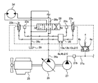
- FIG. 2 is a diagram schematically showing a part of a hydraulic circuit system applied to a hydraulic excavator, together with related configurations. Note that FIG. 2 represents the configuration of the swivel hydraulic motor 3d among the plurality of hydraulic actuators of the hydraulic excavator 1.
- the hydraulic circuit system includes an engine 25 which is a prime mover, a hydraulic pump 26 and a pilot pump 27 driven by the engine 25, and a plurality of hydraulic actuators driven by pressure oil discharged from the hydraulic pump 26 (FIG. 2).
- the hydraulic pump 26 In No. 2, only the swivel hydraulic motor 3d is shown) and a plurality of direction switching valves (here, the direction switching valve 28 related to the swivel hydraulic motor 3d) for controlling the flow of pressure oil supplied from the hydraulic pump 26 to the plurality of hydraulic actuators.
- a hydraulic pilot type operation device that instructs the operation of a plurality of hydraulic actuators and generates a pilot pressure (operation signal) for switching a plurality of direction switching valves (here, only the operation device 4 related to the turning operation). (Illustrated).
- the direction switching valve 28 is a center bypass type and has a center bypass passage located on the center bypass line 28a.
- the center bypass passage is connected in series with the center bypass line 28a, and when the spool of the directional control valve 28 is in the neutral position, the center bypass passage is communicated with the center bypass line 28a, and the spool of the directional switching valve 28 is shown in the figure. 2
- the center bypass passage is cut off from the center bypass line 28a.
- the upstream side of the center bypass line 28a is connected to the discharge line 26a of the hydraulic pump 26, and the downstream side of the center bypass line 28a is connected to the pressure oil tank 29 via the tank line 29a.
- the operating device 4 is, for example, an operating lever, and has a pair of pilot valves that generate a pilot pressure using the discharge pressure of the pilot pump 27 as the original pressure according to the operating amount (tilt amount). Further, the operation device 4 includes operation amount sensors 4a and 4b that electrically detect the amount of inclination of the operation lever in each direction, that is, the lever operation amount, respectively, and the lever operation detected by the operation amount sensors 4a and 4b. The amount is output to the control device 20.
- the direction switching valve 28 is switched by the pilot pressure (operation signal) from the operation device 4. Therefore, for example, when the operation device 4 is operated from the neutral position in the direction corresponding to the left turn (for example, the left side), the pilot pressure generated by one of the pilot valves according to the operation amount is used as an operation signal for the direction switching valve 28.
- the output is output to the pressure receiving unit on the right side in FIG. 2, whereby the direction switching valve 28 is switched to the switching position on the right side in FIG. 2, the swivel hydraulic motor 3d rotates, and the upper swivel body 1d with respect to the lower traveling body 1e. It is designed to turn to the left.
- the pilot pressure generated by the other pilot valve according to the amount of operation is used as an operation signal for the direction switching valve 28.
- the direction switching valve 28 is switched to the switching position on the left side in FIG. 2, the swivel hydraulic motor 3d rotates, and the upper swivel body 1d with respect to the lower traveling body 1e. It is designed to turn to the right.
- Solenoid valves 23a and 23b are provided in the pipelines from the operating device 4 to the two pressure receiving portions of the direction switching valve 28, respectively.
- the solenoid valves 23a and 23b constitute a limiting device that limits the pilot pressure (operation signal) output from the operating device 4 to the direction switching valve 28, and the solenoid valve current (command signal) from the control device 20 described later. ), By limiting the pilot pressure (operation signal), the operating speed of the swing hydraulic motor 3d, which is a hydraulic actuator, is limited.
- this control will be referred to as operation restriction control as necessary.
- pressure sensors 23c and 23d are provided in the pipelines from the solenoid valves 23a and 23b to the two pressure receiving portions of the direction switching valve 28, respectively.
- the pressure sensors 23c and 23d detect the pressure of the pilot pressure (operation signal) supplied to the direction switching valve 28 via the solenoid valves 23a and 23b, and output the detection result to the control device 20.
- the discharge line 27a of the pilot pump 27 is provided with a pilot relief valve (not shown) that keeps the discharge pressure of the pilot pump 27 constant. Further, a lock valve 27b is provided on the discharge line 27a of the pilot pump 27, and the lock valve 27b is switched according to the operation of the gate lock lever provided in the driver's cab 1f.
- the gate lock lever has a position switch (not shown) that is closed when the gate lock lever 4f is in the unlocked position (lowering position) and opened when the gate lock lever 4f is in the locked position (rising position). ..
- the solenoid portion of the lock valve 27b is energized via the position switch, and the lock valve 27b is switched to the communication position.
- the discharge line 27a of the pilot pump 27 is communicated with each other, and the discharge pressure of the pilot pump 27 is introduced into the operating device 4 and the like. That is, the pilot pressure can be generated by operating the operating device 4 and the like, and the hydraulic actuator can be operated (workable state).
- the gate lock lever is operated to the raised position and the position switch is opened, the lock valve 27b is switched to the shutoff position. As a result, the discharge line 27a of the pilot pump 27 is cut off. That is, even if the operating device 4 or the like is operated, the pilot pressure is not generated, and the hydraulic actuator does not operate (work impossible state).
- the hydraulic circuit systems related to the left and right traveling hydraulic motors 3e and 3f, the boom cylinder 3a, the arm cylinder 3b, and the bucket cylinder 3c also have the same configuration as the hydraulic circuit system related to the swivel hydraulic motor 3d.
- solenoid valves 24a and 24b are provided in the conduits from the operating device related to the traveling operation to the two pressure receiving portions of the direction switching valves of the traveling hydraulic motors 3e and 3f, respectively.
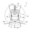
- FIG. 3 is a top view schematically showing the arrangement and detection range of the sensors of the hydraulic excavator.
- a plurality of sensors 13a, 13b, 13c for detecting an object around the upper swing body 1d are mounted on the left, right, left, right, and rear of the upper part of the upper swing body 1d.
- the sensors 13a, 13b, and 13c form a part of a surrounding monitoring system (described later) that monitors the surroundings as an operation support for the operator in the hydraulic excavator 1.
- the plurality of sensors 13a, 13b, 13c are referred to as a rear sensor 13a, a right side sensor 13b, and a left side sensor 13c, respectively, depending on their arrangement.
- the plurality of sensors 13a, 13b, 13c are provided on the rear side of the upper swivel body 1d and on the right side of the upper swivel body 1d and the rear sensor 13a having a detectable range 131a behind the upper swivel body 1d.
- detection ranges 14, 15 and 16 for detecting an object by the sensors 13a, 13b and 13c are set around the hydraulic excavator 1.
- the detection range 14 is a detection range determined based on the turning range of the rear end of the upper turning body 1d when the upper turning body 1d makes a turning operation with respect to the lower traveling body 1e.
- the detection range 15 is a detection range determined on the rear side in the traveling operation of the lower traveling body 1e based on the width of the lower traveling body 1e and the traveling speed (travelable speed).
- the detection range 16 is a detection range determined based on the turning range of the tip of the front working machine 1A when the upper turning body 1d makes a turning operation with respect to the lower traveling body 1e.
- the sensors 13a, 13b, 13c detect the distance and direction from the sensors 13a, 13b, 13c to the object, and output the position of the detected object in the three-dimensional coordinate system as a detection result.
- an infrared depth sensor Is.
- the sensors 13a, 13b, and 13c may be used as long as they can detect an object and specify their positions.
- a millimeter wave sensor or a sensor using a stereo camera may be used. Since the relative mounting positions of the sensors 13a, 13b, 13c with respect to the upper swivel body 1d are predetermined by design information and the like, the upper swivel of the detected object is based on the design information and the detection results of the sensors 13a, 13b, 13c.
- the relative position with respect to the body 1d can be specified.
- the hydraulic excavator 1 of the present embodiment configured as described above has an ambient monitoring system that monitors the surroundings of the hydraulic excavator 1 based on the detection results of the sensors 13a, 13b, and 13c as driving support for the operator. ..
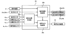
- FIG. 4 is a functional block diagram schematically showing the configuration related to the surrounding monitoring system of the hydraulic excavator according to the present embodiment.
- the surrounding monitoring system includes a plurality of sensors 13a, 13b, 13c, pressure sensors 23c, 23d, operation amount sensors 4a, 4b, an instruction device 31 for instructing ON / OFF of operation restriction control, and restrictions.
- the electromagnetic valves 23a, 23b, 24a, 24b as devices, the voice output device 30 as a warning device provided in the driver's cab 1f, etc., and the electromagnetic valves 23a, based on the detection results of the plurality of sensors 13a, 13b, 13c. It is composed of a control device 20 that generates and outputs a command signal to 23b, 24a, 24b and a command signal to the voice output device 30.
- the limiting device solenoid valves 23a, 23b, 24a, 24b
- the warning device voice output device 30
- the limiting device limits the running operation and turning operation of the hydraulic excavator 1 by controlling the control device 20 according to the detection results of the sensors 13a, 13b, and 13c (that is, performs operation limiting control) to support the operator's operation. I do.
- the instruction device 31 is provided in the driver's cab 1f, for example, and instructs whether the operation restriction control function is enabled (ON) or disabled (OFF) by the operation of the operator.
- the voice output device 30 which is a warning device, assists the operator in driving by transmitting voice information based on the control by the control device 20 according to the detection results of the sensors 13a, 13b, and 13c.
- the voice output device 30 can output various sounds (voice information) in response to a command from the control device 20.
- the sound output by the voice output device 30 includes, for example, a sound in the first state and a sound in the second state. Both the sound of the first state and the sound of the second state have an alarm (warning) effect, and the sound of the first state has a stronger alarm effect (warning intensity) than the sound of the second state. And.
- the voice output device 30 may output at least two types of sounds (voice, buzzer sound, melody, etc.), that is, the sound in the first state and the sound in the second state.
- a speaker, a buzzer, or the like may be used. is there.
- two or more types of speakers or buzzers having different volume, sound pressure, sound quality, etc. may be used together, or the input signal is changed by one speaker or buzzer to change the volume or sound. It may be configured to change the pressure, sound quality, and the like.
- the voice output device 30 is used as the warning device as an example, but warnings having different warning intensities (for example, a warning in the first state and a warning in the second state) will be given to the operator. Anything that can be emitted can be used as a warning device. That is, for example, instead of the voice output device 30, a display device capable of displaying various information is provided as a warning device, and a warning is issued to the operator by displaying the first state and the second state having different warning intensities. It may be configured as follows. In this case, for example, the operator's warning is issued by displaying the display of the first state and the display of the second state, which have a stronger warning intensity than the display of the second state.
- a light emitting device capable of issuing various states is provided as a warning device, and a warning is given to the operator by the light of the first state and the light of the second state having different warning intensities. It may be configured to emit. In this case, for example, the operator's warning is issued by emitting the light in the first state and the light in the second state, which have a stronger warning intensity than the light in the second state.
- a vibration device capable of transmitting information to the operator by various vibrations is provided as a warning device, and the operator is provided with vibrations in the first state and second states having different warning intensities. May be configured to issue a warning.
- the operator's warning is issued by performing the vibration of the first state and the vibration of the second state, which have a stronger warning intensity than the light of the second state.
- a warning having a different warning intensity may be configured to be issued to the operator.
- the control device 20 has a detection position determination unit 20a, an operation restriction control unit 20b, and a voice output control unit 20c as functional units related to the surrounding monitoring system.
- the detection position determination unit 20a determines the detection position of the detected object based on the detection results of the sensors 13a, 13b, 13c, and outputs the determination result to the operation restriction control unit 20b and the voice output control unit 20c. Further, the detection position determination unit 20a has information on the detection ranges 14, 15 and 16, and compares the detection results (position information) of the sensors 13a, 13b and 13c with the detection ranges 14, 15 and 16. It is possible to determine at which position of the detection range 14, 15 or 16 the detected object is located.
- the determination result of the detection position determination unit 20a that is, the detection
- the solenoid valves 23a, 23b, 24a, 24b as a limiting device that limits the operating signal output from the operating device 4 are controlled based on which of the detection ranges 14, 15, and 16 the position of the object is. This limits at least one of the traveling motion of the lower traveling body 1e and the turning motion of the upper rotating body 1d with respect to the lower traveling body 1e.
- the detection range 14 is set as the detection target range during the turning operation of the upper swing body 1d, and when an object is detected in the detection range 14, a command signal is output to the solenoid valves 23a and 23b to output the upper swing body. Limit the turning motion of 1d.
- the detection range 15 is set as the detection target range during the traveling operation of the lower traveling body 1e, and when an object is detected in the detection range 15, a command signal is output to the solenoid valves 24a and 24b to output the lower traveling body. Limit the running operation of 1e.
- the operation restriction control unit 20b controls the solenoid valves 23a, 23b, 24a, 24b. That is, the operation restriction control is not performed.
- the operation restriction control unit 20b determines whether or not the operation restriction control is effective, that is, whether or not the solenoid valves 23a and 23b are operating normally, based on the detection results from the pressure sensors 23c and 23d. .. Specifically, the operation restriction control is ON, the object is detected by the sensors 13a, 13b, 13c, and the solenoid valves 23a, 23b are controlled from the operation restriction control unit 20b in order to perform the operation restriction control of the turning operation and the traveling operation. , 24a, 24b, that is, when the control to limit (reduce) the pilot pressure to the direction switching valve 28 or the like is performed, the solenoid valves 23a, 23b, 24a, 24b are used.
- the operation restriction control unit 20b By determining whether or not the pressure of the pilot pressure through the valve is limited to a predetermined pressure or less (whether or not the pressure is reduced), it is determined whether or not the operation restriction control is effective (normal) or not (abnormal).
- the operation restriction control unit 20b outputs to the voice output control unit 20c a determination result of whether or not the operation restriction control is effective, that is, whether the solenoid valves 23a, 23b, 24a, and 24b are normal or abnormal, respectively.
- the voice output control unit 20c controls the voice output device 30 based on the determination result of the detection position determination unit 20a, the determination result of the operation restriction control unit 20b, and the detection results of the manipulated variable sensors 4a and 4b. Notify the operator of the detected content.
- FIG. 5 is a flowchart showing the processing contents of the control device.
- the operation restriction control unit 20b and the voice output control unit 20c of the control device 20 first determine whether or not an object has been detected based on the determination result from the detection position determination unit 20a (step S100). If the determination result is NO, the process ends.
- step S110 determines whether or not the operation restriction control is ON (step S110), and if the determination result is YES, the operation restriction control unit 20b determines whether or not the operation restriction control is ON (step S110). It is determined whether or not the operation restriction control is effective (step S120). If the determination result in step S120 is YES, the voice output control unit 20c determines whether or not the operation device 4 is operated based on the detection results from the operation amount sensors 4a and 4b (step S130). ), If the determination result is YES, the voice output device 30 is controlled to output the sound in the second state (step S140), and the process is terminated.
- step S110 determines whether the operation restriction control is OFF or not. If the determination result in step S110 is NO, that is, if the operation restriction control is OFF, the sound in the first state is output (step S141), and the process ends. If the determination result in step S120 is NO, that is, if the operation restriction control is invalid (abnormal), the sound in the first state is output (step S141), and the process ends. Further, when the determination result in step S130 is NO, that is, when the operation device 4 is being operated, the sound in the first state is output (step S141), and the process is terminated.
- steps S100 to S141 are continuously and repeatedly executed based on the base clock and the like related to the operation of the control device 20 in the state where the hydraulic excavator 1 is activated.
- the operator's annoyance is suppressed by switching the alarm sound to a light alarm in a situation where the operator recognizes that a predetermined object to be monitored exists around the work machine. I was trying.
- the operator may not be able to recognize the light alarm. ..
- it is conceivable to improve the safety by performing the operation limit control that limits the operation of the work machine when an object is detected, but when the operation limit control is disabled (OFF).
- the operation restriction control does not always work, such as when an abnormality occurs in the operation restriction control function.
- the operation restriction control when the object is detected by the sensors 13a, 13b, 13c, the operation restriction control is OFF (invalid), the operation restriction control is abnormal, or the operation restriction control is abnormal.
- the sound of the first state when the operating device 4 is being operated, the sound of the first state (warning intensity) indicating that the object has been detected. Is notified to the operator by a sound that is relatively strong with respect to the second state) so that the operator can more reliably notice the alarm, and when the operation restriction control is normal, the operating device 4 operates.
- the operator is notified that an object has been detected by a sound in the second state (a sound whose warning intensity is relatively weaker than the sound in the first state), which is different from the sound in the first state. Since it is configured, it is possible to suppress the troublesomeness of the operator while ensuring the effectiveness of the alarm in the surrounding monitoring.
- the effectiveness of the alarm can be improved by raising the alarm level when the operation lever is operated, that is, transmitting voice information having a large alarm effect to the operator.
- the range in which the prevention of contact between the object and the working machine should be considered differs between the turning motion and the traveling motion.
- the range in which the contact between the work machine and the object should be considered in the turning motion is the detection range 14, and in the traveling motion, the detection range is 15. Therefore, when an object is detected in the detection range 15, it can be said that the operation of the operating device for the turning operation is a low-risk operation, and the operation of the operating device for the traveling operation is a high-risk operation. You can say that.
- the alarm effect is increased (warning intensity is strong) in the case of high-risk lever operation, and the alarm effect is small (warning intensity is weak) in the case of low-risk lever operation, which bothers the operator. It is possible to reduce the risk and increase the safety.
- the operation restriction control when the operation restriction control is ON and there is no lever operation even when the operation restriction control is effective, the detected object and the hydraulic pressure Since there is no possibility of contact with the excavator 1 (front work machine 1A, vehicle body 1B), the second sound, which has a weaker warning intensity than the sound in the first state, is used, so it is unreasonable for risk. It is possible to reduce the annoyance of the operator by not notifying the operator with a strong warning sound.
- a pressure sensor for detecting the pilot pressure guided to the pressure receiving portion of the direction switching valve related to the turning operation and the traveling operation is provided, and whether or not the operation limitation control is effective from the detection result of the pressure sensor.
- the effectiveness of the operation limit control is monitored by determining whether or not, and when the operation limit control is ON, the electromagnetic valve that limits the pilot pressure input to the pressure receiving part of the direction switching valve does not operate due to an abnormality such as a failure. Even in this case, the operator is notified of the abnormality of the operation restriction control by notifying the operator with the sound of the first state with a stronger warning intensity, so that the safety of the entire surrounding monitoring system is further improved. be able to.
- the method of audio output is changed depending on the operation target of the operation device.
- FIG. 6 is a flowchart showing the processing contents of the control device according to the present embodiment.
- the same members as those in the first embodiment are designated by the same reference numerals, and the description thereof will be omitted.
- the operation restriction control unit 20b and the voice output control unit 20c of the control device 20 first determine whether or not an object has been detected based on the determination result from the detection position determination unit 20a (step S100). If the determination result is NO, the process ends.
- step S100 determines whether or not the detection position is within the detection range 14 (see FIG. 3), which is the range related to the turning motion (step S101). ) It is determined whether or not the detection position is within the detection range 15 (see FIG. 3), which is the range related to the traveling operation (step S102), and if the determination results of steps S101 and S102 are both NO, voice output is performed.
- the control unit 20c outputs the sound in the second state (step S142), and ends the process.
- Step S110 when at least one of the determination results in steps S101 and S102 is YES, that is, when the detection position of the object is at least one of the detection ranges 14 and 15, the operation restriction control unit 20b turns on the operation restriction control.
- step S120 it is determined whether or not the operation restriction control is effective. If the determination result in step S120 is YES, the voice output control unit 20c determines whether or not the operation device 4 is being operated based on the detection results from the operation amount sensors 4a and 4b (step S131). ), If the determination result is YES, the voice output device 30 is controlled to output the sound in the second state (step S140), and the process is terminated.
- step S110 determines whether the operation restriction control is OFF or not. If the determination result in step S110 is NO, that is, if the operation restriction control is OFF, the sound in the first state is output (step S141), and the process ends. If the determination result in step S120 is NO, that is, if the operation restriction control is invalid (abnormal), the sound in the first state is output (step S141), and the process ends. Further, when the determination result in step S131 is YES, that is, when the operation device 4 is being operated, the sound in the first state is output (step S141), and the process is terminated.
- steps S100 to S142 are continuously and repeatedly executed based on the base clock and the like related to the operation of the control device 20 in the state where the hydraulic excavator 1 is activated.
- an operation device 4 that outputs an operation signal for operating the vehicle body 1B, the front work machine 1A provided on the vehicle body, and the vehicle body and the front work machine based on the operation of the operator.
- a work machine for example, hydraulic excavator 1
- sensors 13a, 13b, 13c for detecting an object around the vehicle body
- the vehicle body and the front work machine are based on an operation signal from the operation device.
- a control device 20 that controls the operation of the vehicle and controls the operation of limiting the operation of at least one of the vehicle body and the front working machine when the object is detected by the sensor, and the control device that performs the operation.
- the control device includes an instruction device 31 for instructing whether the restriction control is enabled or disabled, and the control device is used when the object is detected by the sensor and the operation restriction control is disabled by the instruction device, or by the sensor.
- the operation device is operated in a state where the object is detected and the operation restriction control is enabled by the instruction device, the operator is notified by a warning of the first state, and the control device uses the sensor.
- the warning intensity of the second state is weaker than that of the first state warning. It was decided to notify the operator.
- the vehicle body 1B can turn with respect to the lower traveling body 1e and the lower traveling body.
- the control device 20 has an upper swivel body 1d provided, and when the object is detected in a predetermined detection range based on the swivel range of the upper swivel body, the control device 20 gives an instruction from the instruction device. When the signal is received and the turning operation of the upper swing body is operated by the operating device, the operator is notified by the sound of the first state.
- the warning of the first state and the warning of the second state are assumed to be sounds.
- the plurality of hydraulic actuators 3d, 3e, 3f for driving the vehicle body 1B and the front work machine 1A The vehicle body by reducing the pressure of the direction switching valve 28 that controls the flow rate of the pressure oil supplied from the hydraulic pump 26 to each of the plurality of hydraulic actuators and the pilot pressure as the operation signal that controls the direction switching valve.
- a limiting device for example, electromagnetic valves 23a, 23b, 24a, 224b that limits the operation of at least one of the front working machines, and a pilot as the operation signal supplied to the direction switching valve via the limiting device.
- the control device includes pressure sensors 23c and 23d for detecting the magnitude of the pressure, and the control device receives an instruction signal from the instruction device when the pilot pressure as the operation signal is lower than a predetermined reference pressure. When the pilot pressure as the operation signal is equal to or higher than the reference pressure, it is determined that the instruction signal from the instruction device is not received.
- the vehicle body 1B, the front work machine 1A provided on the vehicle body, the operation device 4 for outputting the operation signal for operating the vehicle body and the front work machine, and the operation device 4 In a surrounding monitoring system for a work machine (for example, a hydraulic excavator 1), the vehicle body or the front surface when the sensors 13a, 13b, 13c for detecting an object around the vehicle body and the detection signals from the sensors are received.
- a control device 20 having a control function for controlling the operation of the work machine is provided, and when the control device receives the detection signal, whether or not the control function is effective and whether or not the control function is effective and the operation device are operated.
- a warning of the first state is issued. Is issued, and when it is determined that the control function is effective and the operating device is not operated, a warning in the second state, which has a weaker warning intensity than the warning in the first state, is issued. It was decided to send a command to issue.
- the present invention is not limited to the above-described embodiment, and includes various modifications and combinations within a range that does not deviate from the gist thereof. Further, the present invention is not limited to the one including all the configurations described in the above-described embodiment, and includes the one in which a part of the configurations is deleted. Further, each of the above configurations, functions and the like may be realized by designing a part or all of them by, for example, an integrated circuit. Further, each of the above configurations, functions, and the like may be realized by software by the processor interpreting and executing a program that realizes each function.
Landscapes
- Engineering & Computer Science (AREA)
- Mining & Mineral Resources (AREA)
- Civil Engineering (AREA)
- General Engineering & Computer Science (AREA)
- Structural Engineering (AREA)
- Business, Economics & Management (AREA)
- Emergency Management (AREA)
- Physics & Mathematics (AREA)
- General Physics & Mathematics (AREA)
- Component Parts Of Construction Machinery (AREA)
- Operation Control Of Excavators (AREA)
Abstract
車体1Bおよびフロント作業機1Aとを備えた油圧ショベル1において、車体1Bの周囲の物体を検知するセンサ13a,13b,13cによって物体が検知されている場合に、車体1Bおよびフロント作業機1Aの少なくとも一方の動作を制限する動作制限制御が有効である場合、又は、操作装置4が操作されている場合には、物体が検知されたことを第一状態の警告によってオペレータに報知し、動作制限制御が有効である場合、かつ、操作装置4が操作されていない場合には、物体が検知されたことを第一状態の警告よりも警告強度の弱い第二状態の警告によってオペレータに報知する。これにより、周囲監視における警報の実効性を確保しつつ、オペレータの煩わしさを抑制することができ、なおかつ安全性能を高めることができる。
Description
本発明は、作業機械および周囲監視システムに関する。
油圧ショベルなどの作業機械においては、オペレータの運転支援に関する技術として作業機械の周囲監視を補助するものが知られている。例えば、特許文献1には、作業機械の周辺の所定範囲内に存在する所定の物体を検知する物体検知部と、前記物体検知部により前記物体が検知された場合、音による警報を行う警報部と、を備え、前記警報部は、前記物体検知部により前記物体が検知された状態が継続している場合、所定の条件が成立したときに、前記音による警報を停止すると共に、前記音による警報の停止後、光による警報を行う作業機械用周辺監視システムが開示されている。
上記従来技術においては、作業機械の周辺に監視対象である所定の物体が存在していることをオペレータが認識しているような状況で警報音を光による警報に切り換えることによってオペレータの煩わしさの抑制を図っている。しかしながら、例えば、直射日光によって光による警報のオペレータからの視認性が著しく低下してしまう場合や、オペレータが光による警報を見ていない場合などには、オペレータが光による警報を認識できないおそれがある。また、作業機械の周囲監視において、物体を検知した際に作業機械の動作を制限することで安全性を高めることも考えられるが、種々の要因によって動作を制限する機能が必ずしも働く状況であるとは限られず、周囲監視におけるオペレータの運転支援としては検討の余地が残されている。
本発明は上記に鑑みてなされたものであり、周囲監視における警報の実効性を確保しつつ、オペレータの煩わしさを抑制することができ、なおかつ安全性能を高めた作業機械および周囲監視システムを提供することを目的とする。
本願は上記課題を解決する手段を複数含んでいるが、その一例を挙げるならば、車体と、前記車体に設けられたフロント作業機と、前記車体および前記フロント作業機を操作する操作信号をオペレータの操作に基づいて出力する操作装置と、前記車体の周囲の物体を検知するセンサと、を備えた作業機械において、前記操作装置からの操作信号に基づいて前記車体および前記フロント作業機の動作を制御するとともに、前記センサにより前記物体が検知された場合に、前記操作信号を制限することで前記車体および前記フロント作業機の少なくとも一方の動作を制限する動作制限制御を行う制御装置と、前記制御装置に前記動作制限制御の有効と無効を指示する指示装置と、を備え、前記制御装置は、前記センサによって前記物体が検知されているときに、前記指示装置により前記動作制限制御が無効とされている状態、または前記指示装置により前記動作制限制御が有効とされた状態で前記操作装置が操作されている場合には第一状態の警告によって前記オペレータに報知し、前記制御装置は、前記センサによって前記物体が検知されているときに、前記指示装置により前記動作制限制御が有効とされた状態で前記操作装置が操作されていない場合には前記第一状態の警告よりも警告強度が弱い第二状態の警告によって前記オペレータに報知するものとする。
本発明によれば、作業機械の周囲監視における警報の実効性を確保しつつ、オペレータの煩わしさを抑制することがで、なおかつ安全性能を高めることができる。
以下、本発明の実施の形態を図面を参照しつつ説明する。なお、本実施の形態では、作業機械の一例とし、油圧ショベルを示して説明するが、クレーンやホイールローダのような他の作業機械にも本発明を適用することが可能である。
<第1の実施の形態>
本発明の第1の実施の形態を図1~図5を参照しつつ説明する。
本発明の第1の実施の形態を図1~図5を参照しつつ説明する。
図1は、本実施の形態に係る作業機械の一例である油圧ショベルの外観を概略的に示す斜視図である。
図1において、油圧ショベル1は、クローラ式の下部走行体1e及び下部走行体1eに対して旋回可能に設けられた上部旋回体1dにより構成された車体1Bと、上部旋回体1dの前側に俯仰動可能に設けられたフロント作業機1Aとから概略構成されている。
フロント作業機1Aは、垂直方向にそれぞれ回動する複数の被駆動部材(ブーム1a、アーム1b、及びバケット1c)を連結して構成されている。ブーム1aの基端は上部旋回体1dの前部に回動可能に支持されている。また、ブーム1aの先端にはアーム1bの一端が回動可能に連結されており、アーム1bの他端(先端)にはバケット1cが回動可能に連結されている。ブーム1a、アーム1b、及びバケット1cは、油圧アクチュエータであるブームシリンダ3a、アームシリンダ3b、及びバケットシリンダ3cによってそれぞれ駆動される。
下部走行体1eは、左右一対のクローラフレームにそれぞれ掛け回された一対のクローラを図示しない減速機構等を介してそれぞれ油圧アクチュエータとしての走行油圧モータ3e,3fで駆動して走行するように構成されている。なお、図1において、走行油圧モータ3e,3fは、左右一対の構成のうちの一方のみを図示して符号を付し、他方の構成については図中に括弧書きの符号のみを示して図示を省略する。
上部旋回体1dは、基部となる旋回フレーム上に各部材を配置して構成されており、旋回フレームが油圧アクチュエータである旋回油圧モータ3dにより下部走行体1eに対して旋回駆動されることにより、上部旋回体1dが下部走行体1eに対して旋回可能となっている。
上部旋回体1dの旋回フレーム上の前側には、オペレータが搭乗して油圧ショベル1の操作を行うための運転室1fが配置されているほか、原動機であるエンジン25、エンジン25により駆動される油圧ポンプ26及びパイロットポンプ27、各油圧アクチュエータ(走行油圧モータ3e,3f、旋回油圧モータ3d、ブームシリンダ3a、アームシリンダ3b、バケットシリンダ3c)を駆動するための油圧回路システムなどが搭載されている(図2参照)。また、上部旋回体1dには、油圧ショベル1の全体の動作を制御する制御装置20が配置されている。
運転室1f内には、オペレータが着座する座席や、フロント作業機1Aの駆動操作、上部旋回体1dの旋回操作、下部走行体1eの走行操作などを行う操作装置4(図2参照)、ゲートロックレバー、座席に着座したオペレータが見やすい位置であって外部視野の妨げにならない位置に配置されたモニタなどが設けられている。なお、運転室1f内に配置された構成については図1における図示を省略する。
図2は、油圧ショベルに適用される油圧回路システムの一部を関連構成とともに抜き出して模式的に示す図である。なお、図2においては、油圧ショベル1の複数の油圧アクチュエータのうち旋回油圧モータ3dに係る構成を代表して示している。
図2において、油圧回路システムは、原動機であるエンジン25と、エンジン25によって駆動される油圧ポンプ26及びパイロットポンプ27と、油圧ポンプ26から吐出された圧油により駆動される複数の油圧アクチュエータ(図2では旋回油圧モータ3dのみを図示)と、油圧ポンプ26から複数の油圧アクチュエータに供給される圧油の流れを制御する複数の方向切換弁(ここでは、旋回油圧モータ3dに係る方向切換弁28のみを図示)と、複数の油圧アクチュエータの動作を指示し、複数の方向切換弁を切り換えるパイロット圧(操作信号)を生成する油圧パイロット式の操作装置(ここでは、旋回操作に係る操作装置4のみを図示)とを備えている。
方向切換弁28は、センタバイパス型であり、センタバイパスライン28a上に位置するセンタバイパス通路を有している。センタバイパス通路は、センタバイパスライン28aに直列に接続されており、方向切換弁28のスプールが中立位置にあるときはセンタバイパス通路をセンタバイパスライン28aと連通し、方向切換弁28のスプールが図2中左側又は右側の切換位置に切り換えられるとセンタバイパス通路をセンタバイパスライン28aから遮断するようになっている。センタバイパスライン28aの上流側は油圧ポンプ26の吐出ライン26aに接続され、センタバイパスライン28aの下流側はタンクライン29aを介して圧油タンク29に接続されている。
操作装置4は、例えば操作レバーであり、その操作量(傾倒量)に応じてパイロットポンプ27の吐出圧を元圧としてパイロット圧を生成する一対のパイロット弁を有している。また、操作装置4は、操作レバーの各方向への傾倒量、すなわちレバー操作量をそれぞれ電気的に検知する操作量センサ4a,4bを含んでおり、操作量センサ4a,4bが検出したレバー操作量は制御装置20に出力される。
方向切換弁28は、操作装置4からのパイロット圧(操作信号)によって切り換えられる。したがって、例えば、操作装置4を中立位置から左旋回に対応する方向(例えば左側)に操作すると、その操作量に応じて一方のパイロット弁で生成されたパイロット圧が操作信号として方向切換弁28の図2中右側の受圧部へ出力され、これによって方向切換弁28が図2中右側の切換位置に切り換えられ、旋回油圧モータ3dが回転して、上部旋回体1dが下部走行体1eに対して左方向に旋回するようになっている。一方、例えば、操作装置4を中立位置から右旋回に対応する方向(例えば右側)に操作すると、その操作量に応じて他方のパイロット弁で生成されたパイロット圧が操作信号として方向切換弁28の図2中左側の受圧部へ出力され、これによって方向切換弁28が図2中左側の切換位置に切り換えられ、旋回油圧モータ3dが回転して、上部旋回体1dが下部走行体1eに対して右方向に旋回するようになっている。
操作装置4から方向切換弁28の2つの受圧部への管路には、それぞれ、電磁弁23a,23bが設けられている。電磁弁23a,23bは、操作装置4から方向切換弁28に出力されるパイロット圧(操作信号)を制限する制限装置を構成するものであり、後述する制御装置20からの電磁弁電流(指令信号)に基づいてパイロット圧(操作信号)を制限することにより油圧アクチュエータである旋回油圧モータ3dの動作速度を制限する。以降、この制御を必要に応じて動作制限制御と称する。
また、電磁弁23a,23bから方向切換弁28の2つの受圧部への管路には、それぞれ、圧力センサ23c,23dが設けられている。圧力センサ23c,23dは、電磁弁23a,23bを介して方向切換弁28に供給されるパイロット圧(操作信号)の圧力を検出し、検出結果を制御装置20に出力する。
パイロットポンプ27の吐出ライン27aには、パイロットポンプ27の吐出圧を一定に保持するパイロットリリーフ弁(図示せず)が設けられている。また、パイロットポンプ27の吐出ライン27aにはロック弁27bが設けられており、このロック弁27bは、運転室1f内に設けられたゲートロックレバーの操作に応じて切り換えられる。ゲートロックレバーは、ゲートロックレバー4fがロック解除位置(下降位置)にある場合に閉じ状態、ロック位置(上昇位置)にある場合に開き状態となるポジションスイッチ(図示せず)を有している。例えば、ゲートロックレバーが下降位置に操作されてポジションスイッチが閉じ状態になると、ポジションスイッチを介してロック弁27bのソレノイド部が通電され、ロック弁27bが連通位置に切り換えられる。これにより、パイロットポンプ27の吐出ライン27aが連通されて、パイロットポンプ27の吐出圧が操作装置4などに導入される。すなわち、操作装置4などの操作によるパイロット圧の生成が可能となり、油圧アクチュエータを作動させることができる(作業可能状態)。一方、ゲートロックレバーが上昇位置に操作されてポジションスイッチが開き状態になると、ロック弁27bが遮断位置に切り換えられる。これにより、パイロットポンプ27の吐出ライン27aが遮断される。すなわち、操作装置4などを操作してもパイロット圧が生成されない状態となり、油圧アクチュエータが作動しないようになっている(作業不可状態)。
なお、図2に図示しない左右の走行油圧モータ3e,3f、ブームシリンダ3a、アームシリンダ3b、及びバケットシリンダ3cに係る油圧回路システムも旋回油圧モータ3dに係る油圧回路システムと同様の構成を備えている。例えば、走行操作に係る操作装置から走行油圧モータ3e,3fのそれぞれの方向切換弁の2つの受圧部への管路には、それぞれ、電磁弁24a,24b(後の図4参照)が設けられており、制御装置20からの電磁弁電流(指令信号)に基づいてパイロット圧(操作信号)を制限することにより油圧アクチュエータである走行油圧モータ3e,3fの動作速度を制限する(すなわち、動作制限制御を行う)。
図3は、油圧ショベルのセンサの配置および検知範囲を模式的に示す上面図である。
図1及び図3に示すように、上部旋回体1dの上部の左右および後方には、上部旋回体1dの周囲の物体を検知するための複数のセンサ13a,13b,13cが搭載されている。センサ13a,13b,13cは、油圧ショベル1におけるオペレータの運転支援として周囲監視を行う周囲監視システム(後述)の一部を構成している。複数のセンサ13a,13b,13cは、その配置に応じて、それぞれ、後方センサ13a、右側方センサ13b、及び左側方センサ13cと称する。すなわち、複数のセンサ13a,13b,13cは、上部旋回体1dの後方に設けられて上部旋回体1dの後方を検知可能範囲131aとする後方センサ13aと、上部旋回体1dの右側方に設けられて上部旋回体1dの右側方を検知可能範囲131bとする右側方センサ13bと、上部旋回体1dの左側方に設けられて上部旋回体1dの左側方を検知可能範囲131cとする左側方センサ13cとから構成されている。
また、図3に示すように、油圧ショベル1の周囲には、センサ13a,13b,13cによる物体の検知を行う検知範囲14,15,16が設定されている。検知範囲14は、上部旋回体1dが下部走行体1eに対して旋回動作を行う場合の上部旋回体1dの後端の旋回範囲に基づいて定められた検知範囲である。検知範囲15は、下部走行体1eの走行動作における後方側に下部走行体1eの幅および走行速度(走行可能速度)に基づいて定められた検知範囲である。検知範囲16は、上部旋回体1dが下部走行体1eに対して旋回動作を行う場合のフロント作業機1Aの先端の旋回範囲に基づいて定められた検知範囲である。
センサ13a,13b,13cは、センサ13a,13b,13cから物体までの距離および方向を検知し、検知した物体の3次元座標系における位置を検知結果として出力するものであり、例えば、赤外線深度センサである。なお、センサ13a,13b,13cは、物体を検知してその位置を特定することができれば良く、例えば、ミリ波センサやステレオカメラを用いたセンサなどを用いても良い。センサ13a,13b,13cの上部旋回体1dに対する相対的な取り付け位置は設計情報などにより予め定められているので、設計情報とセンサ13a,13b,13cの検知結果とから、検知した物体の上部旋回体1dに対する相対位置(3次元座標系における相対位置)を特定することができる。
以上のように構成した本実施の形態の油圧ショベル1は、オペレータの運転支援として、センサ13a,13b,13cの検知結果に基づいて油圧ショベル1の周囲監視を行う周囲監視システムを有している。
図4は、本実施の形態に係る油圧ショベルの周囲監視システムに係る構成を抜き出して模式的に示す機能ブロック図である。
図4において、周囲監視システムは、複数のセンサ13a,13b,13cと、圧力センサ23c,23dと、操作量センサ4a,4bと、動作制限制御のON/OFFを指示する指示装置31と、制限装置としての電磁弁23a,23b,24a,24bと、運転室1f等に設けられた警告装置としての音声出力装置30と、複数のセンサ13a,13b,13cの検知結果に基づいて電磁弁23a,23b,24a,24bへの指令信号と音声出力装置30への指令信号とを生成して出力する制御装置20とから構成されている。
ここで、制限装置(電磁弁23a,23b,24a,24b)及び警告装置(音声出力装置30)は、オペレータの運転支援を行う運転支援装置の一部を構成している。
制限装置は、センサ13a,13b,13cの検知結果に応じた制御装置20の制御により、油圧ショベル1の走行動作や旋回動作を制限する(すなわち、動作制限制御を行う)ことでオペレータの運転支援を行う。指示装置31は、例えば、運転室1f内に設けらえており、オペレータの操作によって動作制限制御の機能を有効(ON)とするか無効(OFF)とするかを指示する。
警告装置である音声出力装置30は、センサ13a,13b,13cの検知結果に応じた制御装置20による制御に基づいて音声情報を伝えることでオペレータの運転支援を行う。音声出力装置30は、制御装置20からの指令に応じて種々の音(音声情報)を出力することができる。音声出力装置30が出力する音には、例えば、第一状態の音と第二状態の音とがある。第一状態の音および第二状態の音はともに警報(警告)効果を有するものであり、第一状態の音の方が第二状態の音に比べてより警報効果(警告強度)が強いものとする。具体的には、例えば、第二状態の音と比較して、第一状態の音の音を大きくしたり、音圧を大きくしたり、人がより認識しやすい周波数にしたりすることが考えられる。
なお、音声出力装置30は、少なくとも第一状態の音と第二状態の音の2種類の音(音声、ブザー音、メロディ、など)を出力可能であれば良く、例えば、スピーカーやブザー等である。また、音声出力装置30としては、音量や音圧、音質などの異なる2種類以上のスピーカーやブザーを併せて用いてもよいし、或いは1つのスピーカーやブザーで入力信号を変化させて音量や音圧、音質などを変えるように構成してもよい。
また、本実施の形態においては、警告装置として音声出力装置30を用いる場合を例示して説明するが、警告強度の異なる警告(例えば、第一状態の警告と第二状態の警告)をオペレータに対して発することができるものであれば警告装置として用いることができる。すなわち、例えば、音声出力装置30に代えて、種々の情報を表示可能な表示装置を警告装置として備え、警告強度の異なる第一状態の表示および第二状態の表示によってオペレータに対して警告を発するように構成しても良い。この場合には、例えば、第二状態の表示よりも警告強度が強い第一状態の表示と、第二状態の表示とを表示することでオペレータの警告を発する。また、例えば、音声出力装置30に代えて、種々の状態の発行が可能な発光装置を警告装置として備え、警告強度の異なる第一状態の光および第二状態の光によってオペレータに対して警告を発するように構成しても良い。この場合には、例えば、第二状態の光よりも警告強度が強い第一状態の光と、第二状態の光とを発することでオペレータの警告を発する。また、例えば、音声出力装置30に代えて、種々の振動によってオペレータに情報を報知可能な振動装置を警告装置として備え、警告強度の異なる第一状態の振動および第二状態の振動によってオペレータに対して警告を発するように構成しても良い。この場合には、例えば、第二状態の光よりも警告強度が強い第一状態の振動と、第二状態の振動とを行うことでオペレータの警告を発する。また、これらの組み合わせによって警告強度の異なる警告(例えば、第一状態の警告と第二状態の警告)をオペレータに対して発するように構成しても良い。
制御装置20は、周囲監視システムに係る機能部として、検知位置判定部20aと、動作制限制御部20bと、音声出力制御部20cとを有している。
検知位置判定部20aは、センサ13a,13b,13cの検知結果に基づいて、検知された物体の検知位置を判定し、判定結果を動作制限制御部20b及び音声出力制御部20cに出力する。また、検知位置判定部20aは、検知範囲14,15,16の情報を有しており、センサ13a,13b,13cの検知結果(位置情報)と検知範囲14,15,16とを比較することで、検知された物体が検知範囲14,15,16の何れの位置にあるかを判定することができる。
動作制限制御部20bは、オペレータの指示装置31の操作によって動作制限制御をONとする(機能を有効とする)指示がなされている場合には、検知位置判定部20aの判定結果、すなわち、検知された物体の位置が検知範囲14,15,16の何れであるかに基づいて、操作装置4から出力される操作信号を制限する制限装置としての電磁弁23a,23b,24a,24bを制御することにより、下部走行体1eの走行動作と上部旋回体1dの下部走行体1eに対する旋回動作との少なくとも何れか一方を制限する。例えば、上部旋回体1dの旋回動作中には検知範囲14を検知対象の範囲とし、検知範囲14において物体を検知した場合には、電磁弁23a,23bに指令信号を出力することで上部旋回体1dの旋回動作を制限する。また、下部走行体1eの走行動作中には検知範囲15を検知対象の範囲とし、検知範囲15において物体を検知した場合には、電磁弁24a,24bに指令信号を出力することで下部走行体1eの走行動作を制限する。なお、オペレータの指示装置31の操作によって動作制限制御をOFFとする(機能を無効とする)指示がなされている場合には、動作制限制御部20bは電磁弁23a,23b,24a,24bの制御、すなわち、動作制限制御を行わない。
また、動作制限制御部20bは、圧力センサ23c,23dからの検出結果に基づいて、動作制限制御が有効か否か、すなわち、電磁弁23a,23bが正常に動作しているか否かを判定する。具体的には、動作制限制御がONであって、センサ13a,13b,13cによって物体が検知され、旋回動作や走行動作の動作制限制御を行うために動作制限制御部20bから電磁弁23a,23b,24a,24bへの指令信号を出力した場合、すなわち、方向切換弁28などへのパイロット圧を制限する(減圧する)制御が行われている場合に、電磁弁23a,23b,24a,24bを介したパイロット圧の圧力が予め定めた圧力以下に制限されているか(減圧されているか)否かを判定することで、動作制限制御が有効(正常)か否(異常)かを判定する。動作制限制御部20bは、動作制限制御が有効か否かの判定結果、すなわち、電磁弁23a,23b,24a,24bがそれぞれ正常であるか異常であるかを音声出力制御部20cに出力する。
音声出力制御部20cは、検知位置判定部20aの判定結果と、動作制限制御部20bの判定結果と、操作量センサ4a,4bの検出結果とに基づいて音声出力装置30を制御することにより、オペレータへの検知内容の報知を行う。
図5は、制御装置の処理内容を示すフローチャートである。
図5において、制御装置20の動作制限制御部20b及び音声出力制御部20cは、まず、検知位置判定部20aからの判定結果に基づいて、物体が検知されたか否かを判定し(ステップS100)、判定結果がNOの場合には、処理を終了する。
また、ステップS100での判定結果がYESである場合には、動作制限制御部20bは、動作制限制御がONであるか否かを判定し(ステップS110)、判定結果がYESの場合には、動作制限制御が有効であるか否かを判定する(ステップS120)。ステップS120での判定結果がYESの場合には、音声出力制御部20cは、操作量センサ4a,4bからの検出結果に基づいて、操作装置4が操作されているか否かを判定し(ステップS130)、判定結果がYESの場合には、音声出力装置30を制御して第二状態の音を出力し(ステップS140)、処理を終了する。
また、ステップS110の判定結果がNOの場合、すなわち、動作制限制御がOFFである場合には、第一状態の音を出力し(ステップS141)、処理を終了する。また、ステップS120の判定結果がNOの場合に、すなわち、動作制限制御が無効である場合(異常である場合)には、第一状態の音を出力し(ステップS141)、処理を終了する。また、ステップS130での判定結果がNOの場合、すなわち、操作装置4の操作が行われている場合には、第一状態の音を出力し(ステップS141)、処理を終了する。
なお、図5に示す処理(ステップS100~S141)は、油圧ショベル1が起動している状態においては、制御装置20の動作に係るベースクロック等に基づいて継続的に繰り返し実行される。
以上のように構成した本実施の形態における効果を説明する。
従来技術においては、作業機械の周辺に監視対象である所定の物体が存在していることをオペレータが認識しているような状況で警報音を光による警報に切り換えることによってオペレータの煩わしさの抑制を図っていた。しかしながら、例えば、直射日光によって光による警報のオペレータからの視認性が著しく低下してしまう場合や、オペレータが光による警報を見ていない場合などには、オペレータが光による警報を認識できないおそれがある。また、作業機械の周囲監視において、物体を検知した際に作業機械の動作を制限する動作制限制御を行うことで安全性を高めることも考えられるが、動作制限制御を無効(OFF)としている場合や、動作制限制御の機能に異常が生じている場合など、動作制限制御が必ずしも働く状況であるとは限られない。
これに対して本実施の形態においては、センサ13a,13b,13cによって物体が検知されている場合に、動作制限制御がOFF(無効)とされている場合、動作制限制御が異常である場合、又は、操作装置4が操作されている場合などのように、潜在的に作業機械と物体との接触の可能性が高まる場合には、物体が検知されたことを第一状態の音(警告強度が第二状態に対して相対的に強い音)によってオペレータに報知することで、オペレータがより確実に警報に気づくようにするとともに、動作制限制御が正常である場合、かつ、操作装置4が操作されていない場合には、物体が検知されたことを第一状態の音とは異なる第二状態の音(警告強度が第一状態に対して相対的に弱い音)によってオペレータに報知するように構成したので、周囲監視における警報の実効性を確保しつつ、オペレータの煩わしさを抑制することができる。
すなわち、例えば、物体を検知して警報が鳴っている場合に、オペレータが警報に気づいていない場合、または、警報には気付いているが一定時間が経過したことによって警報に対する意識が薄れてしまっている場合には、操作レバーを操作してしまう恐れがある。したがって、このような場合には、操作レバーを操作した際に警報レベルを上げる、すなわち、警報効果の大きい音声情報をオペレータに伝えることにより、警報の実効性を向上させることができる。
また、油圧ショベルなどの旋回動作を行う作業機械の場合には、旋回動作と走行動作とで物体と作業機械との接触防止を考慮すべき範囲(すなわち、物体を検知すべき範囲)が異なる。例えば、図3に示したように、旋回動作において作業機械と物体との接触を考慮すべき範囲は検知範囲14であり、走行動作においては検知範囲15である。したがって、検知範囲15で物体を検知している場合には、旋回動作のための操作装置の操作は低リスクの操作であるといえるし、走行動作のための操作装置の操作はリスクの高い操作であるといえる。このように、リスクが高いレバー操作の場合には警報効果を大きく(警告強度を強く)、リスクが低いレバー操作の場合には警報効果を小さく(警告強度を弱く)することで、オペレータの煩わしさを低減することができ、なおかつ安全性を高めることができる。
また、本実施の形態においては、例えば、図5に示したように、動作制限制御がONであり、かつ、有効である場合であってもレバー操作が無い場合には、検知した物体と油圧ショベル1(フロント作業機1A、車体1B)との接触の可能性が無いため、第一状態の音よりも警告強度の弱い第二の音を用いるように構成したので、リスクに対して不当に警告強度の強い音でオペレータに報知することがなくなり、オペレータの煩わしさを低減することができる。
また、本実施の形態においては、旋回動作や走行動作に係る方向切換弁の受圧部に導かれるパイロット圧を検出する圧力センサを設け、圧力センサの検出結果から動作制限制御が有効であるか否かを判定することで動作制限制御の実効性を監視し、動作制限制御がONの場合に、方向切換弁の受圧部に入力されるパイロット圧を制限する電磁弁が故障などの異常によって動作しない場合であっても、より警告強度の強い第一状態の音でオペレータに報知することで、動作制限制御の異常をオペレータに報知するよう構成したので、周囲監視システム全体の安全性をより向上することができる。
<第2の実施の形態>
本発明の第2の実施の形態を図6を参照しつつ説明する。
本発明の第2の実施の形態を図6を参照しつつ説明する。
本実施の形態は、操作装置の操作対象によって音声出力の仕方を変えたものである。
図6は、本実施の形態に係る制御装置の処理内容を示すフローチャートである。図中、第1の実施の形態と同様の部材には同じ符号を付し、説明を省略する。
図6において、制御装置20の動作制限制御部20b及び音声出力制御部20cは、まず、検知位置判定部20aからの判定結果に基づいて、物体が検知されたか否かを判定し(ステップS100)、判定結果がNOの場合には、処理を終了する。
また、ステップS100での判定結果がYESの場合、すなわち、物体が検知された場合には、検知位置が旋回動作に係る範囲である検知範囲14(図3参照)であるか否かと(ステップS101)、検知位置が走行動作に係る範囲である検知範囲15(図3参照)であるか否かとを判定し(ステップS102)、ステップS101,S102の判定結果がともにNOの場合には、音声出力制御部20cは、第二状態の音を出力し(ステップS142)、処理を終了する。
また、ステップS101,S102の少なくとも一方の判定結果がYESの場合、すなわち、物体の検知位置が検知範囲14,15の少なくとも一方である場合には、動作制限制御部20bは、動作制限制御がONであるか否かを判定し(ステップS110)、判定結果がYESの場合には、動作制限制御が有効であるか否かを判定する(ステップS120)。ステップS120での判定結果がYESの場合には、音声出力制御部20cは、操作量センサ4a,4bからの検出結果に基づいて、操作装置4が操作されているか否かを判定し(ステップS131)、判定結果がYESの場合には、音声出力装置30を制御して第二状態の音を出力し(ステップS140)、処理を終了する。
また、ステップS110の判定結果がNOの場合、すなわち、動作制限制御がOFFである場合には、第一状態の音を出力し(ステップS141)、処理を終了する。また、ステップS120の判定結果がNOの場合に、すなわち、動作制限制御が無効である場合(異常である場合)には、第一状態の音を出力し(ステップS141)、処理を終了する。また、ステップS131での判定結果がYESの場合、すなわち、操作装置4の操作が行われている場合には、第一状態の音を出力し(ステップS141)、処理を終了する。
なお、図6に示す処理(ステップS100~S142)は、油圧ショベル1が起動している状態においては、制御装置20の動作に係るベースクロック等に基づいて継続的に繰り返し実行される。
その他の構成は第1の実施の形態と同様である。
以上のように構成した本実施の形態においても第1の実施の形態と同様の効果を得ることができる。
以上のように構成した本実施の形態の特徴を説明する。
(1)上記の実施の形態では、車体1Bと、前記車体に設けられたフロント作業機1Aと、前記車体および前記フロント作業機を操作する操作信号をオペレータの操作に基づいて出力する操作装置4と、前記車体の周囲の物体を検知するセンサ13a,13b,13cと、を備えた作業機械(例えば、油圧ショベル1)において、前記操作装置からの操作信号に基づいて前記車体および前記フロント作業機の動作を制御するとともに、前記センサにより前記物体が検知された場合に、前記車体および前記フロント作業機の少なくとも一方の動作を制限する動作制限制御を行う制御装置20と、前記制御装置に前記動作制限制御の有効と無効を指示する指示装置31と、を備え、前記制御装置は、前記センサによって前記物体が検知され前記指示装置により前記動作制限制御が無効とされている場合、または前記センサによって前記物体が検知され前記指示装置により前記動作制限制御が有効とされた状態で前記操作装置が操作されている場合には第一状態の警告によって前記オペレータに報知し、前記制御装置は、前記センサによって前記物体が検知され前記指示装置により前記動作制限制御が有効とされた状態で前記操作装置が操作されていない場合には前記第一状態の警告よりも警告強度が弱い第二状態の警告によって前記オペレータに報知するものとした。
これにより、作業機械の周囲監視における警報の実効性を確保しつつ、オペレータの煩わしさを抑制することができ、なおかつ安全性能を高めることができる。
(2)また、上記の実施の形態では、上記(1)の作業機械(例えば、油圧ショベル1)において、前記車体1Bは、下部走行体1e、及び、前記下部走行体に対して旋回可能に設けられた上部旋回体1dとを有し、前記制御装置20は、前記上部旋回体の旋回範囲に基づいて予め定められた検知範囲において前記物体が検知されているとき、前記指示装置からの指示信号を受信し、かつ前記操作装置によって前記上部旋回体の旋回動作が操作されている場合には、前記第一状態の音によって前記オペレータに報知するものとした。
(3)また、上記の実施の形態では、上記(1)の作業機械(例えば、油圧ショベル1)において、前記第一状態の警告および前記第二状態の警告は音であるものとした。
(4)また、上記の実施の形態では、上記(1)の作業機械(例えば、油圧ショベル1)において、前記車体1Bおよび前記フロント作業機1Aを駆動する複数の油圧アクチュエータ3d,3e,3fと、油圧ポンプ26から前記複数の油圧アクチュエータのそれぞれに供給される圧油の流量を制御する方向切換弁28と、前記方向切換弁を制御する前記操作信号としてのパイロット圧を減圧することで前記車体および前記フロント作業機の少なくとも一方の動作を制限する制限装置(例えば、電磁弁23a,23b,24a,224b)と、前記制限装置を介して前記方向切換弁に供給される前記操作信号としてのパイロット圧の大きさを検出する圧力センサ23c,23dとを備え、前記制御装置は、前記操作信号としてのパイロット圧が予め定めた基準圧力よりも低い場合に前記指示装置からの指示信号を受信していると判定し、前記操作信号としてのパイロット圧が前記基準圧力以上の場合に記指示装置からの指示信号を受信していないと判定するものとした。
(5)また、上記の実施の形態では、車体1Bと、前記車体に設けられたフロント作業機1Aと、前記車体および前記フロント作業機を操作するための操作信号を出力する操作装置4と、を備える作業機械(例えば、油圧ショベル1)のための周囲監視システムにおいて、前記車体の周囲の物体を検知するセンサ13a,13b,13cと前記センサからの検知信号を受信したとき前記車体または前記フロント作業機の動作を制御する制御機能を有する制御装置20と、を備え、前記制御装置は、前記検知信号を受信したときに、前記制御機能が有効であるか否かと、前記操作装置が操作されているか否かとを判定し、前記制御機能が無効であると判定した場合、または前記制御機能が有効で前記操作装置が操作されていると判定した場合には、第一状態の警告を発するための指令を発信し、前記制御機能が有効であると判定し、かつ前記操作装置が操作されていないと判定した場合には前記第一状態の警告よりも警告強度が弱い第二状態の警告を発するための指令を発信するものとした。
<付記>
なお、本発明は上記の実施の形態に限定されるものではなく、その要旨を逸脱しない範囲内の様々な変形例や組み合わせが含まれる。また、本発明は、上記の実施の形態で説明した全ての構成を備えるものに限定されず、その構成の一部を削除したものも含まれる。また、上記の各構成、機能等は、それらの一部又は全部を、例えば集積回路で設計する等により実現してもよい。また、上記の各構成、機能等は、プロセッサがそれぞれの機能を実現するプログラムを解釈し、実行することによりソフトウェアで実現してもよい。
なお、本発明は上記の実施の形態に限定されるものではなく、その要旨を逸脱しない範囲内の様々な変形例や組み合わせが含まれる。また、本発明は、上記の実施の形態で説明した全ての構成を備えるものに限定されず、その構成の一部を削除したものも含まれる。また、上記の各構成、機能等は、それらの一部又は全部を、例えば集積回路で設計する等により実現してもよい。また、上記の各構成、機能等は、プロセッサがそれぞれの機能を実現するプログラムを解釈し、実行することによりソフトウェアで実現してもよい。
1…油圧ショベル、1A…フロント作業機、1B…車体、1a…ブーム、1b…アーム、1c…バケット、1d…上部旋回体、1e…下部走行体、1f…運転室、3a…ブームシリンダ、3b…アームシリンダ、3c…バケットシリンダ、3d…旋回油圧モータ、3e…走行油圧モータ、3f…走行油圧モータ、4…操作装置、4a,4b…操作量センサ、4f…ゲートロックレバー、13a…後方センサ、13b…右側方センサ、13c…左側方センサ、14,15,16…検知範囲、20…制御装置、20a…検知位置判定部、20b…動作制限制御部、20c…音声出力制御部、23a,23b,24a,24b…電磁弁、23c,23d…圧力センサ、25…エンジン、26…油圧ポンプ、26a…吐出ライン、27…パイロットポンプ、27a…吐出ライン、27b…ロック弁、28…方向切換弁、28a…センタバイパスライン、29…圧油タンク、29a…タンクライン、30…音声出力装置、31…指示装置、131a,131b,131c…検知可能範囲
Claims (5)
- 車体と、
前記車体に設けられたフロント作業機と、
前記車体および前記フロント作業機を操作する操作信号をオペレータの操作に基づいて出力する操作装置と、
前記車体の周囲の物体を検知するセンサと、を備えた作業機械において、
前記操作装置からの操作信号に基づいて前記車体および前記フロント作業機の動作を制御するとともに、前記センサにより前記物体が検知された場合に、前記車体および前記フロント作業機の少なくとも一方の動作を制限する動作制限制御を行う制御装置と、
前記制御装置に前記動作制限制御の有効と無効を指示する指示装置と、を備え、
前記制御装置は、前記センサによって前記物体が検知され前記指示装置により前記動作制限制御が無効とされている場合、または前記センサによって前記物体が検知され前記指示装置により前記動作制限制御が有効とされた状態で前記操作装置が操作されている場合には第一状態の警告によって前記オペレータに報知し、
前記制御装置は、前記センサによって前記物体が検知され前記指示装置により前記動作制限制御が有効とされた状態で前記操作装置が操作されていない場合には前記第一状態の警告よりも警告強度が弱い第二状態の警告によって前記オペレータに報知することを特徴とする作業機械。 - 請求項1記載の作業機械において、
前記車体は、下部走行体、及び、前記下部走行体に対して旋回可能に設けられた上部旋回体とを有し、
前記制御装置は、前記上部旋回体の旋回範囲に基づいて予め定められた検知範囲において前記物体が検知されているとき、前記指示装置からの指示信号を受信し、かつ前記操作装置によって前記上部旋回体の旋回動作が操作されている場合には、前記第一状態の警告によって前記オペレータに報知することを特徴とする作業機械。 - 請求項1記載の作業機械において、
前記第一状態の警告および前記第二状態の警告は音であることを特徴とする作業機械。 - 請求項1記載の作業機械において、
前記車体および前記フロント作業機を駆動する複数の油圧アクチュエータと、
油圧ポンプから前記複数の油圧アクチュエータのそれぞれに供給される圧油の流量を制御する方向切換弁と、
前記方向切換弁を制御する前記操作信号としてのパイロット圧を減圧することで前記車体および前記フロント作業機の少なくとも一方の動作を制限する制限装置と、
前記制限装置を介して前記方向切換弁に供給される前記操作信号としてのパイロット圧の大きさを検出する圧力センサとを備え、
前記制御装置は、前記操作信号としてのパイロット圧が予め定めた基準圧力よりも低い場合に前記指示装置からの指示信号を受信していると判定し、前記操作信号としてのパイロット圧が前記基準圧力以上の場合に記指示装置からの指示信号を受信していないと判定することを特徴とする作業機械。 - 車体と、
前記車体に設けられたフロント作業機と、前記車体および前記フロント作業機を操作するための操作信号を出力する操作装置と、を備える作業機械のための周囲監視システムにおいて、
前記車体の周囲の物体を検知するセンサと
前記センサからの検知信号を受信したとき前記車体または前記フロント作業機の動作を制御する制御機能を有する制御装置と、を備え、
前記制御装置は、前記検知信号を受信したときに、前記制御機能が有効であるか否かと、前記操作装置が操作されているか否かとを判定し、
前記制御機能が無効であると判定した場合、または前記制御機能が有効で前記操作装置が操作されていると判定した場合には、第一状態の警告を発するための指令を発信し、
前記制御機能が有効であると判定し、かつ前記操作装置が操作されていないと判定した場合には前記第一状態の警告よりも警告強度が弱い第二状態の警告を発するための指令を発信することを特徴とする周囲監視システム。
Priority Applications (4)
| Application Number | Priority Date | Filing Date | Title |
|---|---|---|---|
| US17/641,536 US11885108B2 (en) | 2019-10-31 | 2020-10-28 | Work machine and periphery monitoring system |
| CN202080063235.9A CN114364847B (zh) | 2019-10-31 | 2020-10-28 | 作业机械以及周围监视系统 |
| KR1020227004087A KR102646808B1 (ko) | 2019-10-31 | 2020-10-28 | 작업 기계 및 주위 감시 시스템 |
| EP20881632.2A EP4012121A4 (en) | 2019-10-31 | 2020-10-28 | CONSTRUCTION MACHINERY AND ENVIRONMENTAL MONITORING SYSTEM |
Applications Claiming Priority (2)
| Application Number | Priority Date | Filing Date | Title |
|---|---|---|---|
| JP2019-199394 | 2019-10-31 | ||
| JP2019199394A JP7153627B2 (ja) | 2019-10-31 | 2019-10-31 | 作業機械および周囲監視システム |
Publications (1)
| Publication Number | Publication Date |
|---|---|
| WO2021085500A1 true WO2021085500A1 (ja) | 2021-05-06 |
Family
ID=75712686
Family Applications (1)
| Application Number | Title | Priority Date | Filing Date |
|---|---|---|---|
| PCT/JP2020/040509 Ceased WO2021085500A1 (ja) | 2019-10-31 | 2020-10-28 | 作業機械および周囲監視システム |
Country Status (6)
| Country | Link |
|---|---|
| US (1) | US11885108B2 (ja) |
| EP (1) | EP4012121A4 (ja) |
| JP (1) | JP7153627B2 (ja) |
| KR (1) | KR102646808B1 (ja) |
| CN (1) | CN114364847B (ja) |
| WO (1) | WO2021085500A1 (ja) |
Families Citing this family (20)
| Publication number | Priority date | Publication date | Assignee | Title |
|---|---|---|---|---|
| US11607654B2 (en) | 2019-12-30 | 2023-03-21 | Marathon Petroleum Company Lp | Methods and systems for in-line mixing of hydrocarbon liquids |
| CA3103416C (en) | 2019-12-30 | 2022-01-25 | Marathon Petroleum Company Lp | Methods and systems for inline mixing of hydrocarbon liquids |
| CA3104319C (en) | 2019-12-30 | 2023-01-24 | Marathon Petroleum Company Lp | Methods and systems for spillback control of in-line mixing of hydrocarbon liquids |
| US11578836B2 (en) | 2021-03-16 | 2023-02-14 | Marathon Petroleum Company Lp | Scalable greenhouse gas capture systems and methods |
| US12012883B2 (en) | 2021-03-16 | 2024-06-18 | Marathon Petroleum Company Lp | Systems and methods for backhaul transportation of liquefied gas and CO2 using liquefied gas carriers |
| US11655940B2 (en) | 2021-03-16 | 2023-05-23 | Marathon Petroleum Company Lp | Systems and methods for transporting fuel and carbon dioxide in a dual fluid vessel |
| US11578638B2 (en) | 2021-03-16 | 2023-02-14 | Marathon Petroleum Company Lp | Scalable greenhouse gas capture systems and methods |
| US12180597B2 (en) | 2021-08-26 | 2024-12-31 | Marathon Petroleum Company Lp | Test station assemblies for monitoring cathodic protection of structures and related methods |
| US12043905B2 (en) | 2021-08-26 | 2024-07-23 | Marathon Petroleum Company Lp | Electrode watering assemblies and methods for maintaining cathodic monitoring of structures |
| US11447877B1 (en) | 2021-08-26 | 2022-09-20 | Marathon Petroleum Company Lp | Assemblies and methods for monitoring cathodic protection of structures |
| US12129559B2 (en) | 2021-08-26 | 2024-10-29 | Marathon Petroleum Company Lp | Test station assemblies for monitoring cathodic protection of structures and related methods |
| US11686070B1 (en) | 2022-05-04 | 2023-06-27 | Marathon Petroleum Company Lp | Systems, methods, and controllers to enhance heavy equipment warning |
| JP7472934B2 (ja) * | 2022-05-19 | 2024-04-23 | コベルコ建機株式会社 | 作業機械の安全装置 |
| JP2024004570A (ja) * | 2022-06-29 | 2024-01-17 | ヤンマーホールディングス株式会社 | 作業機械の制御方法、作業機械用制御プログラム、作業機械用制御システム及び作業機械 |
| US12012082B1 (en) | 2022-12-30 | 2024-06-18 | Marathon Petroleum Company Lp | Systems and methods for a hydraulic vent interlock |
| US12006014B1 (en) | 2023-02-18 | 2024-06-11 | Marathon Petroleum Company Lp | Exhaust vent hoods for marine vessels and related methods |
| US12043361B1 (en) | 2023-02-18 | 2024-07-23 | Marathon Petroleum Company Lp | Exhaust handling systems for marine vessels and related methods |
| JP2025007151A (ja) * | 2023-06-30 | 2025-01-17 | 株式会社小松製作所 | 作業機械の監視システム及び作業機械の監視方法 |
| US12297965B2 (en) | 2023-08-09 | 2025-05-13 | Marathon Petroleum Company Lp | Systems and methods for mixing hydrogen with natural gas |
| US12597151B2 (en) | 2023-09-18 | 2026-04-07 | Marathon Petroleum Company Lp | Systems and methods to determine vegetation encroachment along a right-of-way |
Citations (8)
| Publication number | Priority date | Publication date | Assignee | Title |
|---|---|---|---|---|
| JP2004076351A (ja) * | 2002-08-14 | 2004-03-11 | Hitachi Constr Mach Co Ltd | 建設機械の警報装置 |
| JP2005248502A (ja) * | 2004-03-03 | 2005-09-15 | Hitachi Constr Mach Co Ltd | 作業機の干渉防止装置 |
| WO2015121818A2 (en) * | 2014-02-12 | 2015-08-20 | Advanced Microwave Engineering S.R.L. | System for preventing collisions between self-propelled vehicles and obstacles in workplaces or the like |
| JP2017172223A (ja) * | 2016-03-24 | 2017-09-28 | 株式会社日立建機ティエラ | 小型の油圧ショベル |
| WO2018105527A1 (ja) * | 2016-12-06 | 2018-06-14 | 住友建機株式会社 | 建設機械 |
| JP2018111981A (ja) | 2017-01-11 | 2018-07-19 | 住友建機株式会社 | 作業機械用周辺監視システム |
| WO2019111859A1 (ja) * | 2017-12-04 | 2019-06-13 | 住友重機械工業株式会社 | 周辺監視装置、情報処理端末、情報処理装置、情報処理プログラム |
| JP2019157409A (ja) * | 2018-03-08 | 2019-09-19 | 大成建設株式会社 | 作業車両用旋回制御システム及び作業車両用警報制御システム |
Family Cites Families (32)
| Publication number | Priority date | Publication date | Assignee | Title |
|---|---|---|---|---|
| JPH06272283A (ja) * | 1993-03-24 | 1994-09-27 | Yutani Heavy Ind Ltd | 建設機械の制御装置 |
| US7334658B2 (en) * | 2004-12-23 | 2008-02-26 | Caterpillar Inc. | Steering system with joystick mounted controls |
| KR101069450B1 (ko) * | 2005-03-04 | 2011-09-30 | 히다찌 겐끼 가부시키가이샤 | 작업 기계의 안전 장치 및 작업 기계의 서비스 시스템 |
| JP5064976B2 (ja) * | 2007-11-12 | 2012-10-31 | クラリオン株式会社 | 建設・土木作業車両の作業安全監視システム |
| JP5271758B2 (ja) * | 2009-03-11 | 2013-08-21 | 日立建機株式会社 | 作業機械の油圧駆動装置 |
| JP5248377B2 (ja) * | 2009-03-16 | 2013-07-31 | 日立建機株式会社 | 作業機械の油圧駆動装置 |
| JP5079827B2 (ja) * | 2010-02-10 | 2012-11-21 | 日立建機株式会社 | 油圧ショベルの油圧駆動装置 |
| JP5363407B2 (ja) * | 2010-04-26 | 2013-12-11 | 日立建機株式会社 | 建設機械の表示装置 |
| JP5719440B2 (ja) * | 2010-09-09 | 2015-05-20 | ボルボ コンストラクション イクイップメント アーベー | 建設機械用可変容量型油圧ポンプの流量制御装置 |
| KR101751405B1 (ko) * | 2010-10-22 | 2017-06-27 | 히다치 겡키 가부시키 가이샤 | 작업 기계의 주변 감시 장치 |
| US9030332B2 (en) * | 2011-06-27 | 2015-05-12 | Motion Metrics International Corp. | Method and apparatus for generating an indication of an object within an operating ambit of heavy loading equipment |
| US20140118533A1 (en) * | 2012-01-27 | 2014-05-01 | Doosan Infracore Co., Ltd. | Operational stability enhancing device for construction machinery |
| JP6456584B2 (ja) * | 2013-03-19 | 2019-01-23 | 住友重機械工業株式会社 | 作業機械用周辺監視装置 |
| US10316492B2 (en) * | 2014-07-31 | 2019-06-11 | Cnh Industrial America Llc | Active force/vibration feedback control method and apparatus for a movable machine |
| US9975472B2 (en) * | 2015-04-30 | 2018-05-22 | Tyri International, Inc. | Controllable lighting arrangement for a vehicle |
| JP6567941B2 (ja) * | 2015-10-06 | 2019-08-28 | 日立建機株式会社 | 建設機械 |
| CN111953942B (zh) | 2015-11-30 | 2022-07-12 | 住友重机械工业株式会社 | 施工机械用周边监视系统 |
| US10344450B2 (en) * | 2015-12-01 | 2019-07-09 | The Charles Machine Works, Inc. | Object detection system and method |
| JP6572156B2 (ja) * | 2016-03-02 | 2019-09-04 | 株式会社神戸製鋼所 | 建設機械の干渉防止装置 |
| WO2017154188A1 (ja) * | 2016-03-10 | 2017-09-14 | 日立建機株式会社 | 建設機械 |
| CN107949676B (zh) * | 2016-03-31 | 2020-10-27 | 日立建机株式会社 | 工程机械的驱动控制装置 |
| JP6712936B2 (ja) * | 2016-09-23 | 2020-06-24 | 株式会社小松製作所 | 作業車両の管理システム及び作業車両の管理方法 |
| AU2017382930B2 (en) * | 2016-12-23 | 2023-04-20 | Caterpillar Sarl | Monitoring the operation of a work machine |
| GB2558266A (en) * | 2016-12-23 | 2018-07-11 | Caterpillar Inc | Work tool positioning system |
| JP6775602B2 (ja) * | 2016-12-28 | 2020-10-28 | 株式会社小松製作所 | 作業車両および作業車両の制御システム |
| JP6760163B2 (ja) * | 2017-03-22 | 2020-09-23 | コベルコ建機株式会社 | 建設機械 |
| JP6581139B2 (ja) * | 2017-03-31 | 2019-09-25 | 日立建機株式会社 | 作業機械の周囲監視装置 |
| CN110121739B (zh) * | 2017-12-06 | 2022-02-22 | 株式会社小松制作所 | 作业车辆的周边监视系统及作业车辆的周边监视方法 |
| JP7039983B2 (ja) * | 2017-12-13 | 2022-03-23 | コベルコ建機株式会社 | 建設機械用の注意喚起装置 |
| JP6900897B2 (ja) * | 2017-12-25 | 2021-07-07 | コベルコ建機株式会社 | 建設機械の障害物検出装置 |
| JP7265323B2 (ja) * | 2018-07-31 | 2023-04-26 | 株式会社小松製作所 | 作業機械を制御するためのシステム及び方法 |
| WO2020204239A1 (ko) * | 2019-04-05 | 2020-10-08 | 볼보 컨스트럭션 이큅먼트 에이비 | 건설기계 |
-
2019
- 2019-10-31 JP JP2019199394A patent/JP7153627B2/ja active Active
-
2020
- 2020-10-28 KR KR1020227004087A patent/KR102646808B1/ko active Active
- 2020-10-28 CN CN202080063235.9A patent/CN114364847B/zh active Active
- 2020-10-28 EP EP20881632.2A patent/EP4012121A4/en active Pending
- 2020-10-28 US US17/641,536 patent/US11885108B2/en active Active
- 2020-10-28 WO PCT/JP2020/040509 patent/WO2021085500A1/ja not_active Ceased
Patent Citations (8)
| Publication number | Priority date | Publication date | Assignee | Title |
|---|---|---|---|---|
| JP2004076351A (ja) * | 2002-08-14 | 2004-03-11 | Hitachi Constr Mach Co Ltd | 建設機械の警報装置 |
| JP2005248502A (ja) * | 2004-03-03 | 2005-09-15 | Hitachi Constr Mach Co Ltd | 作業機の干渉防止装置 |
| WO2015121818A2 (en) * | 2014-02-12 | 2015-08-20 | Advanced Microwave Engineering S.R.L. | System for preventing collisions between self-propelled vehicles and obstacles in workplaces or the like |
| JP2017172223A (ja) * | 2016-03-24 | 2017-09-28 | 株式会社日立建機ティエラ | 小型の油圧ショベル |
| WO2018105527A1 (ja) * | 2016-12-06 | 2018-06-14 | 住友建機株式会社 | 建設機械 |
| JP2018111981A (ja) | 2017-01-11 | 2018-07-19 | 住友建機株式会社 | 作業機械用周辺監視システム |
| WO2019111859A1 (ja) * | 2017-12-04 | 2019-06-13 | 住友重機械工業株式会社 | 周辺監視装置、情報処理端末、情報処理装置、情報処理プログラム |
| JP2019157409A (ja) * | 2018-03-08 | 2019-09-19 | 大成建設株式会社 | 作業車両用旋回制御システム及び作業車両用警報制御システム |
Non-Patent Citations (1)
| Title |
|---|
| See also references of EP4012121A4 |
Also Published As
| Publication number | Publication date |
|---|---|
| CN114364847A (zh) | 2022-04-15 |
| EP4012121A1 (en) | 2022-06-15 |
| US11885108B2 (en) | 2024-01-30 |
| US20220290411A1 (en) | 2022-09-15 |
| KR102646808B1 (ko) | 2024-03-13 |
| CN114364847B (zh) | 2023-06-30 |
| EP4012121A4 (en) | 2023-08-30 |
| KR20220028126A (ko) | 2022-03-08 |
| JP2021071015A (ja) | 2021-05-06 |
| JP7153627B2 (ja) | 2022-10-14 |
Similar Documents
| Publication | Publication Date | Title |
|---|---|---|
| JP7153627B2 (ja) | 作業機械および周囲監視システム | |
| JP7340710B2 (ja) | 作業機械および作業機械の制御システム | |
| CN107923155A (zh) | 工程机械的安全装置 | |
| WO2021049409A1 (ja) | 建設機械 | |
| JP7478275B2 (ja) | 油圧ショベル | |
| JP7112935B2 (ja) | 作業機械 | |
| JP7201548B2 (ja) | 作業機械 | |
| JP7514248B2 (ja) | 作業機械 | |
| JP5986042B2 (ja) | 建設機械の走行警報装置 | |
| KR20230067601A (ko) | 작업 차량 | |
| CN120359337A (zh) | 工程机械的控制系统及控制方法 | |
| JP6695288B2 (ja) | 建設機械 | |
| JP7328082B2 (ja) | 建設機械 | |
| JP3338653B2 (ja) | 作業機械の安全装置 | |
| JP2024052153A (ja) | 建設機械 | |
| CN120712390A (zh) | 回转式工程机械的控制装置 | |
| JP2003216157A (ja) | 建設機械の警報装置 |
Legal Events
| Date | Code | Title | Description |
|---|---|---|---|
| 121 | Ep: the epo has been informed by wipo that ep was designated in this application |
Ref document number: 20881632 Country of ref document: EP Kind code of ref document: A1 |
|
| ENP | Entry into the national phase |
Ref document number: 20227004087 Country of ref document: KR Kind code of ref document: A |
|
| ENP | Entry into the national phase |
Ref document number: 2020881632 Country of ref document: EP Effective date: 20220308 |
|
| NENP | Non-entry into the national phase |
Ref country code: DE |