WO2021085574A1 - 靴の中敷き - Google Patents
靴の中敷き Download PDFInfo
- Publication number
- WO2021085574A1 WO2021085574A1 PCT/JP2020/040727 JP2020040727W WO2021085574A1 WO 2021085574 A1 WO2021085574 A1 WO 2021085574A1 JP 2020040727 W JP2020040727 W JP 2020040727W WO 2021085574 A1 WO2021085574 A1 WO 2021085574A1
- Authority
- WO
- WIPO (PCT)
- Prior art keywords
- layer
- support plate
- arch
- hardness
- wall portion
- Prior art date
- Legal status (The legal status is an assumption and is not a legal conclusion. Google has not performed a legal analysis and makes no representation as to the accuracy of the status listed.)
- Ceased
Links
Images


Classifications
-
- A—HUMAN NECESSITIES
- A43—FOOTWEAR
- A43B—CHARACTERISTIC FEATURES OF FOOTWEAR; PARTS OF FOOTWEAR
- A43B17/00—Insoles for insertion, e.g. footbeds or inlays, for attachment to the shoe after the upper has been joined
- A43B17/003—Insoles for insertion, e.g. footbeds or inlays, for attachment to the shoe after the upper has been joined characterised by the material
- A43B17/006—Insoles for insertion, e.g. footbeds or inlays, for attachment to the shoe after the upper has been joined characterised by the material multilayered
-
- A—HUMAN NECESSITIES
- A43—FOOTWEAR
- A43B—CHARACTERISTIC FEATURES OF FOOTWEAR; PARTS OF FOOTWEAR
- A43B17/00—Insoles for insertion, e.g. footbeds or inlays, for attachment to the shoe after the upper has been joined
-
- A—HUMAN NECESSITIES
- A43—FOOTWEAR
- A43B—CHARACTERISTIC FEATURES OF FOOTWEAR; PARTS OF FOOTWEAR
- A43B17/00—Insoles for insertion, e.g. footbeds or inlays, for attachment to the shoe after the upper has been joined
- A43B17/14—Insoles for insertion, e.g. footbeds or inlays, for attachment to the shoe after the upper has been joined made of sponge, rubber, or plastic materials
-
- A—HUMAN NECESSITIES
- A43—FOOTWEAR
- A43B—CHARACTERISTIC FEATURES OF FOOTWEAR; PARTS OF FOOTWEAR
- A43B7/00—Footwear with health or hygienic arrangements
- A43B7/14—Footwear with health or hygienic arrangements with foot-supporting parts
- A43B7/1405—Footwear with health or hygienic arrangements with foot-supporting parts with pads or holes on one or more locations, or having an anatomical or curved form
- A43B7/1415—Footwear with health or hygienic arrangements with foot-supporting parts with pads or holes on one or more locations, or having an anatomical or curved form characterised by the location under the foot
- A43B7/142—Footwear with health or hygienic arrangements with foot-supporting parts with pads or holes on one or more locations, or having an anatomical or curved form characterised by the location under the foot situated under the medial arch, i.e. under the navicular or cuneiform bones
-
- A—HUMAN NECESSITIES
- A43—FOOTWEAR
- A43B—CHARACTERISTIC FEATURES OF FOOTWEAR; PARTS OF FOOTWEAR
- A43B7/00—Footwear with health or hygienic arrangements
- A43B7/14—Footwear with health or hygienic arrangements with foot-supporting parts
- A43B7/1405—Footwear with health or hygienic arrangements with foot-supporting parts with pads or holes on one or more locations, or having an anatomical or curved form
- A43B7/1415—Footwear with health or hygienic arrangements with foot-supporting parts with pads or holes on one or more locations, or having an anatomical or curved form characterised by the location under the foot
- A43B7/143—Footwear with health or hygienic arrangements with foot-supporting parts with pads or holes on one or more locations, or having an anatomical or curved form characterised by the location under the foot situated under the lateral arch, i.e. the cuboid bone
-
- A—HUMAN NECESSITIES
- A61—MEDICAL OR VETERINARY SCIENCE; HYGIENE
- A61F—FILTERS IMPLANTABLE INTO BLOOD VESSELS; PROSTHESES; DEVICES PROVIDING PATENCY TO, OR PREVENTING COLLAPSING OF, TUBULAR STRUCTURES OF THE BODY, e.g. STENTS; ORTHOPAEDIC, NURSING OR CONTRACEPTIVE DEVICES; FOMENTATION; TREATMENT OR PROTECTION OF EYES OR EARS; BANDAGES, DRESSINGS OR ABSORBENT PADS; FIRST-AID KITS
- A61F5/00—Orthopaedic methods or devices for non-surgical treatment of bones or joints; Nursing devices ; Anti-rape devices
- A61F5/01—Orthopaedic devices, e.g. long-term immobilising or pressure directing devices for treating broken or deformed bones such as splints, casts or braces
- A61F5/14—Special medical insertions for shoes for flat-feet, club-feet or the like
Definitions
- the present invention relates to shoe insoles.
- the inventor of the present application wears shoes as an invention similar to the present application.
- shoe insoles that can balance the skeleton of the foot (for example, Patent Document 1 below).
- the shoe insole described in Patent Document 1 is located on the upper surface side of the seat portion on which substantially the entire sole of the foot is arranged, on the central convex portion and both sides thereof so as to face the central portion on the heel side slightly from the ball of the toe.
- a central recess is provided.
- the shoe insole described in Patent Document 1 includes a hard support plate attached so as to substantially cover from substantially the center of the lower surface side of the seat portion to the portion corresponding to the heel.
- the support plate is formed with two rows of through holes for fitting a part of the seat portion substantially along both side edges of the support plate.
- a ridge portion extending in the longitudinal direction of the insole is formed inside the two rows of through holes.
- the foot in particular, is made up of a large number of bones, but because it supports the weight of the entire body, a slight shift in the joints of the foot can cause the posture to become unbalanced.
- the joints of the feet when the joints of the feet are displaced, the joints above the feet try to compensate for the posture collapse, so that a completely different part other than the feet may be burdened daily and the body may be injured. Therefore, it is required to naturally maintain proper joint engagement at a higher level and without unnecessarily restricting the movement of the foot. Therefore, the inventor has developed a shoe insole that can naturally hold the proper meshing of joints at a higher level and without restricting the movement of the foot.
- the insole of the shoe of the present invention has a toe portion formed so as to arrange the toes, an overhang portion formed so as to arrange the tip portion of the metatarsal bone having the width of the foot most protruding to the left and right, and the insole. It has an arch part formed so as to be arranged from the bone to just below the outer malleolus, and a calcaneus part formed so as to arrange the calcaneus directly below the outer malleolus and behind it, and is arranged on the entire bottom surface of the shoe.
- the seat portion and the support plate bonded to the lower surface of the arch portion and the heel portion of the seat portion and formed of a material harder than the seat portion are provided, and the seat portion and the support plate are formed by the arch portion.
- the insole portion which is curved in an arch shape so as to arrange at least the first metatarsal bone and the end portion is raised upward
- the insole shape which is curved so as to arrange at least the fifth metatarsal bone.
- the support plate has an outer wall portion whose end is raised upward and a central wall portion formed between the inner side wall portion and the outer wall portion, and the support plate has the inner side wall portion and the center. It has an inner ridge formed on the boundary with the wall portion and an outer ridge formed on the substantially boundary between the outer wall portion and the central wall portion, and has the inner side wall portion and the outer side of the support plate.
- a plurality of through holes are formed in each of the wall portions along the longitudinal direction of the support plate, and at least the upper surface of the central wall portion located between the inner ridge portion and the outer ridge portion is described as described above. It is curved so as to draw an arch in the longitudinal direction of the support plate. According to this configuration, the arch shape of the central rear wall portion of the seat portion is supported by the upper surface shape of the central rear wall portion of the support plate, and the arch shape can be accurately formed on the foot arranged on the upper surface of the seat portion. It becomes.
- the seat portion and the support plate of the shoe insole of the present invention have an extending portion protruding upward so as to face the base end portion of the heel portion and / or the arch portion located directly below the outer malleolus from the side surface. May be. According to this configuration, the heel portion and / or the base end portion of the arch portion located directly below the lateral malleolus, that is, the lower portion of the cuboid bone can be supported from the outside to prevent the skeleton of the foot from collapsing.
- the support plate of the shoe insole of the present invention may be formed with a hardness of 40D or more and less than 72D, and may be arranged along the lower surface shape of the seat portion with a constant thickness. According to this configuration, the burden on the foot due to the support plate can be reduced.
- the support plate of the shoe insole of the present invention may be formed with a hardness of 40D or more and less than 65D, and may be arranged along the lower surface shape of the seat portion with a constant thickness. According to this configuration, the burden on the foot due to the support plate can be further reduced.
- the heel portion of the support plate of the shoe insole of the present invention may be formed with an opening for fitting a part of the seat portion.
- the arch shape formed by the central rear wall portion of the seat portion and the support plate forms a vertical arch shape on the foot, which makes it easier to ride. It will be easier to keep the balance of the weight you hang.
- the sheet portion of the shoe insole of the present invention includes at least two foaming resin layers having different hardness and elastic modulus, and is provided on the upper surface side first layer and below the first layer. It is preferable that the two layers form a repulsive elastic resin layer containing an ethylene-vinyl acetate copolymer as a main component. Further, it is preferable that the first layer and the second layer have the following relationship between the hardness measured by an Asker rubber hardness tester (C type) and the elastic modulus measured by ISO4662. Measured hardness The first layer ⁇ the second layer elastic modulus The first layer ⁇ the second layer
- the hardness measured by the Asker rubber hardness tester (C type) of the second layer is 50 or more and 60 or less and the elastic modulus measured by ISO4662 is 55% or more and 65% or less. It is more preferable that the hardness of the first layer measured by an Asker rubber hardness tester (C type) is 23 or more and 28 or less, and the elastic modulus measured by ISO4662 is 47% or more and 53% or less.
- the present invention has the effect of making it possible to naturally maintain the proper engagement of the joints of the foot at a higher level and without restricting the movement of the foot.
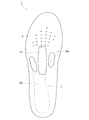
- FIG. 1 is a cross-sectional view taken along the line AA of FIG. It is a top view which shows the insole of the shoe which concerns on one Embodiment of this invention.
- A It is a bottom view which shows the support plate of the insole of the shoe which concerns on one Embodiment of this invention.
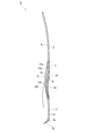
- B It is a cross-sectional view taken along the line BB of this figure (a). It is a left side view which shows the insole of the shoe which concerns on one Embodiment of this invention.
- the shoe insole 1 As shown in FIGS. 1 and 2, the shoe insole 1 according to the embodiment of the present invention includes a seat portion 2 arranged on the entire bottom surface of a shoe (not shown) and a central portion of the seat portion 2 in the longitudinal direction. It is provided with a support plate 3 that covers the seat portion 2 from below over the heel portion.
- the seat portion 2 has a toe portion 4, an overhanging portion 5 having the widest left and right widths, an arch portion 6, and a heel portion 7 from the front end to the rear end.
- the toe portion 4 is a portion formed so as to arrange the toes.
- the overhanging portion 5 is a portion formed so as to arrange the tip end portion (that is, from the ball of the toe to the ball of the small toe) of the metatarsal bone 50 shown in FIG. 3 in which the width of the foot projects most to the left and right.
- the heel portion 7 is a portion formed so as to arrange the calcaneus 62 immediately below and behind the outer malleolus 61 shown in FIG.
- the arch portion 6 is a portion formed so as to be arranged from the metatarsal bone 50 to just below the lateral malleolus 61, excluding the overhanging portion 5 shown in FIG.
- the outer shape of the seat portion 2 is formed so as to roughly follow the outer shape of the foot in a plan view.
- the arch portion 6 of the seat portion 2 mainly arranges the inner side wall portion 8 formed so as to arrange the first metatarsal bone 51 shown in FIG. 3, and the fifth metatarsal bone 55 mainly shown in FIG. It has an outer wall portion 9 formed as described above, and a central wall portion 10 formed between the inner side wall portion 8 and the outer wall portion 9.
- the inner side wall portion 8 is a portion that is curved in an arch shape that protrudes upward so as to mainly arrange the first metatarsal bone 51 shown in FIG. 3, and the end portion is smoothly raised upward. ..
- a plurality of protrusions 11 are formed on the lower surface side of the inner side wall portion 8 at intervals in the longitudinal direction.
- the outer side wall portion 9 is a portion that is curved in an arch shape that protrudes upward so as to mainly arrange the fifth metatarsal bone 55 shown in FIG. 3, and the end portion is raised upward.
- a plurality of protrusions 12 are formed on the lower surface side of the outer side wall portion 9 at intervals in the longitudinal direction.
- the central wall portion 10 has a central front wall portion 10a in which both the upper and lower surfaces are inclined upward in a substantially straight line toward the toe portion 4 and the upper and lower surfaces in the cross-sectional view taken along the line AA of FIG. Both have a central rear wall portion 10b that is curved so as to draw an arch shape in the front-rear direction.
- the central rear wall portion 10b is formed to have a substantially constant thickness, and the central front wall portion 10a is formed to be slightly thicker than the central rear wall portion 10b.
- the heel portion 7 of the seat portion 2 has a rising portion 7w so that the lower end portion of the heel of the foot can be surrounded and held from the side surface side. ..
- the inner side wall portion 8, the rising portion 7w, and the outer wall portion 9 are smoothly connected.
- a thick portion 13 for absorbing the weight applied to the heel portion 7 is formed on the lower surface side of the heel portion 7 of the seat portion 2.
- a central convex portion 14 that rises and extends in the front-rear direction is formed on the upper surface of the seat portion 2 at substantially the center in the width direction of the central front wall portion 10a.
- the central convex portion 14 is formed so as to be able to fit the indentation of the foot immediately posterior to the medial side of the ball that supports the weight when the so-called toe stands.
- the left and right sides of the central convex portion 14 are relatively slightly recessed.
- the sheet portion 2 is molded from rubber, a synthetic resin, or the like, and is preferably molded from a soft synthetic resin such as an ethylene-vinyl acetate copolymer (EVA).
- EVA ethylene-vinyl acetate copolymer
- the hardness of the sheet portion 2 is preferably formed in the range of 22 or more and 80 or less as measured by an Asker rubber hardness tester (C type).
- the support plate 3 covers and adheres from the arch portion 6 to the heel portion 7 along the shape of the seat portion 2.
- the support plate 3 has an arch portion 6'corresponding to each portion of the seat portion 2, an inner side wall portion 8'that constitutes the arch portion 6', an outer wall portion 9', a central front wall portion 10a', and a center. It has a rear wall portion 10b'and a heel portion 7'.
- the heel portion 7'of the support plate 3 also has a rising portion 7w'that surrounds and holds the side surface of the heel of the foot.
- the support plate 3 is provided on the substantially boundary between the inner side wall portion 8'and the central rear wall portion 10b', and between the outer wall portion 9'and the central rear wall portion 10b', that is, on the substantially line L or on the line L.
- it has an inner ridge portion 15 and an outer ridge portion 16, respectively.
- the inner ridge portion 15 is formed in an arch shape substantially parallel to the arch shape that appears at the lower end when the inner side wall portion 8'is viewed from the side.
- the outer ridge portion 16 is formed in an arch shape substantially parallel to the arch shape that appears at the lower end when the outer wall portion 9'is viewed from the side.
- Both the inner ridge portion 15 and the outer ridge portion 16 are formed in a strip shape with a substantially constant width dimension.
- the central front wall portion 10a'of the support plate 3 is formed to have the same shape as the seat portion 2, that is, a substantially flat shape.
- the central rear wall portion 10b'of the support plate 3 has a substantially constant thickness as a whole, and the upper surface and the lower surface thereof are the lower surface of the central rear wall portion 10b of the seat portion 2, the inner ridge portion 15, and the outer ridge portion 16. It forms an arch shape in almost the same longitudinal direction.
- a plurality of through holes 18 are formed at the rising portion of the inner side wall portion 8'at intervals along the longitudinal direction of the support plate 3.
- the through hole 18 formed in the inner side wall portion 8'of the support plate 3 is formed so that the protrusion 11 formed on the lower surface side of the inner side wall portion 8 of the seat portion 2 can be fitted without a gap.
- the lower surface of the support plate 3 and the surface of the protrusion 11 are formed so as to be flush with each other.
- a plurality of through holes 18 are formed in the outer wall portion 9'at intervals along the longitudinal direction of the support plate 3.
- the through hole 18 formed in the outer wall portion 9'of the support plate 3 is formed so that the protrusion 12 formed on the lower surface side of the outer wall portion 9 of the seat portion 2 can be fitted without a gap.
- the lower surface of the support plate 3 and the surface of the protrusion 12 are formed so as to be flush with each other.
- the support plate 3 is formed according to the shape of each portion of the seat portion 2, as shown in FIGS. 1 and 5, the inside thereof has the central rear wall portion 10b'as the boundary with the line L as a boundary. Except for this, the outside of the line L is formed so as to rise smoothly with the line L as a boundary so as to be substantially flat and in contact with a horizontal plane such as the ground. Then, the arch portion 6 can be firmly raised by the central rear wall portion 10b'and the inner ridge portion 15 and the outer ridge portion 16 formed on the substantially line L to support the vertical arch of the foot. it can.
- the heel portion 7'of the support plate 3 is formed with an opening 19 that absorbs and receives the load applied from the heel.
- the opening 19 is formed substantially parallel to the line L on the inner side 7a'and the rear side 7b' of the heel part 7', and extends slightly inward so as to be separated from the line L on the outer side 7c' of the heel part 7'. Further, it extends toward the central rear wall portion 10b', which gradually warps diagonally on the outside of the tip side 7d'.
- the support plate 3 fits closer to the sole of the foot, so that the weight of the heel, tendon, etc. of the foot
- the portion where the support plate 3 is easily applied is susceptible to the load due to the hardness of the support plate 3.
- the opening 19 in the above shape it is possible to effectively reduce the load on the heel and tendon on which a large weight is easily applied, and to maintain a high fit between the seat portion 2 and the support plate 3.
- the thickness of the support plate 3 is constant except for the central front wall portion 10a, the edge surrounding each through hole 18 and the opening 19, and the edge which is the outer peripheral edge of the support plate 3. It is formed to have a thickness of 1.1 mm or more and less than 2.1 mm, preferably about 2 mm.
- the central front wall portion 10a'of the support plate 3 is formed to be about 10% thinner than the central rear wall portion 10b', the heel portion 7', etc., and specifically, to have a thickness of 1.0 mm or more and less than 1.9 mm. ing.
- the outer peripheral edge of the support plate 3, the through hole 18 and the edge forming the opening 19 are chamfered so as to be easily fitted to the seat portion 2.
- the inner ridge portion 15 and the outer ridge portion 16 of the support plate 3 protrude from the surface of the central rear wall portion 10b'around the support plate 3 by 0.9 mm or more and less than 1.1 mm, preferably 1.0 mm. Both the inner ridge portion 15 and the outer ridge portion 16 are solidly formed.
- the support plate 3 is made of a hard resin such as thermoplastic polyurethane (TPU).
- TPU thermoplastic polyurethane
- the hardness of the support plate 3 is 40D or more and less than 72D, and 45D or more and less than 65D as measured by an Asker rubber hardness tester (D type).
- the upper surface of the support plate 3 is in close contact with the lower surface of the seat portion 2 by crimping each other so that they cannot be easily separated.
- the through holes 18 and the openings 19 of the support plate 3 are fitted with the corresponding protrusions 11 and 12 and the thick portions 13 formed in the seat portion 2, and are substantially flush with the surface of the support plate 3. It has become.
- the shoe insole 1 of the present invention having the above configuration has the following functions. That is, the lower end of the inner side wall portion 8'of the seat portion 2 and the support plate 3, the lower end of the outer wall portion 9', the inner ridge portion 15, the outer ridge portion 16, and the upper and lower surfaces of the central rear wall portion 10b'are substantially the same.
- the curved vertical arch shape further enhances the elastic force of the vertical arch of the shoe insole 1.
- the arch shape of the medial ridge 15, the lateral ridge 16 and the central rear wall 10b' flexibly and reliably provides the central portion of the arch of the foot in the width direction (between the medial longitudinal arch and the lateral longitudinal arch). It is held in a vertical arch shape.
- a vertical arch shape is firmly formed on the upper and lower surfaces of the central rear wall portion 10b of the seat portion 2, and the vertical arch shape is firmly formed on the upper and lower surfaces of the inner ridge portion 15, the outer ridge portion 16 and the central rear wall portion 10b'of the support plate 3. Therefore, it is possible to prevent the weight of the ball and the small toe ball placed on the overhanging portion 5 and the weight of the heel placed on the heel portion 7 from being biased. Therefore, the shape of the shoe insole 1 can guide the center of gravity to the correct position. Further, each bone and joint of the foot can be appropriately held without forming an unnecessary gap on the sole of the foot, including the central convex portion 14 formed on the central front wall portion 10a of the seat portion 2.
- first metatarsal bone 51, the fifth metatarsal bone 55, and the lower side surface of the heel of the foot shown in FIG. 3 are firmly fixed by the inner side wall portion 8', the outer wall portion 9', and the rising portion 7w'of the heel portion 7'. But you can hold it so that you don't get cramped.
- the intercombination of these actions helps prevent the bones of the foot, which are connected by multiple joints, from shifting or distorting, and helps maintain a properly assembled state, such as walking and other exercises. Occasionally, it has the effect of preventing the occurrence of postural distortion due to the displacement of the leg bones.
- the support plate 3 of the shoe insole 1 of the present invention causes a slight pain in the foot due to long-term use even within the hardness range of the TPU resin generally used in other shoe insoles 1.
- the seat portion 2 and the support plate 3 are located at the base ends of the heel portions 7, 7'and / or the arch portions 6, 6'located directly below the outer malleolus 61 shown in FIG. It is even more preferable to have an extension portion 20 projecting upward so as to face each other from the side surface.
- the extension portion 20 may be formed by both the seat portion 2 and the support plate 3, that is, the peripheral edge of the seat portion 2 and the peripheral edge of the support plate 3 may be substantially parallel to each other in the extension portion 20. According to this configuration, it is possible to prevent the supination of the foot (that is, the movement of the foot to twist around the side on the little finger side).
- the sheet portion 2 may be provided with two foamed resin layers having different hardness and elastic modulus, and the first layer on the upper surface side and the second layer provided below the first layer. It is preferable to form a repulsive elastic resin layer containing an ethylene-vinyl acetate copolymer as a main component. Further, it is preferable that the first layer and the second layer have a relationship in which the hardness measured by an Asker rubber hardness tester (C type) and the elastic modulus measured by ISO4662: 2009 are as shown below. Measurement hardness The first layer ⁇ the second layer, and Repulsive modulus The first layer ⁇ the second layer
- a resin containing EVA as a main component may be used as the first layer, and a resin layer mixed with a shock absorbing material such as polyethylene, polypropylene, or silicone resin may be used to adjust the elastic modulus. it can. More specifically, the hardness measured using an Asker rubber hardness tester (C type) is 23 or more and 28 or less, and the elastic modulus measured by ISO4662: 2009 is 47% or more and 53% or less, more preferably. A resin having a content of 49% or more and 52% or less can be preferably used. Further, the first layer may be a polyurethane foamed resin layer.
- a resin containing EVA as a main component can be used, and in order to adjust the rebound resilience, a resin obtained by compressing a foaming resin containing EVA as a main component can be used. More specifically, it is preferable that the hardness measured by an Asker rubber hardness tester (C type) is 50 or more and 60 or less, and the elastic modulus measured by ISO4662: 2009 is 55% or more and 65% or less. Further, the hardness measured using an Asker rubber hardness tester (C type) is preferably 53 or more and 60 or less, preferably 57% or more and 59% or less.
- the first layer and the second layer are pressed, and a fiber sheet layer is provided on the upper surface of the first layer.
- the first layer is formed to have a thickness of 0.5 mm or more and 4.0 mm or less, although it is not limited.
- the second layer is not limited, but is formed to have a thickness of 1.0 mm or more and 4.0 mm or less.
- the second layer may be formed thicker on the heel than on the toes, and when the first layer is a polyurethane layer, both the first layer and the second layer have EVA in the first layer and the second layer. It may be formed thicker than when it is the main component.
- the first layer is provided with appropriate hardness and resilience to exert cushioning properties for the foot, and the first layer is provided with low hardness, that is, flexibility and low resilience.
- the layer can be firmly held along the shape of the sole of the foot and can support the foot softly. Therefore, the effect is that the skeleton of the foot can be held as correctly as possible and the foot can be effectively protected from the impact on the foot.
- Example 1 With a soft synthetic resin such as ethylene-vinyl acetate copolymer (EVA), a sheet portion 2 having a hardness of about 55 as measured by an Asker rubber hardness tester (C type), and a hard resin such as thermoplastic polyurethane (TPU).
- EVA ethylene-vinyl acetate copolymer
- C type Asker rubber hardness tester
- TPU thermoplastic polyurethane
- Example 2 A shoe insole similar to that of Example 1 was prepared except that the hardness of the support plate 3 was 55D as measured by an Asker rubber hardness tester (D type).
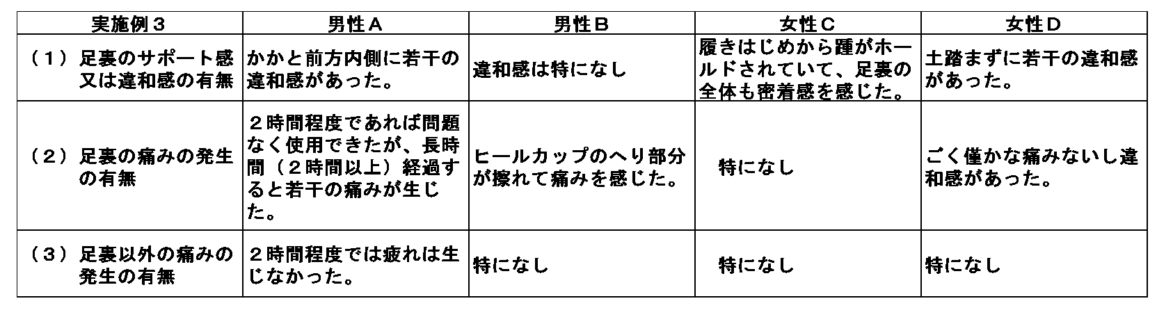
- Example 3 A shoe insole similar to that of Example 1 was prepared except that the hardness of the support plate 3 was 63.5D as measured by using an Asker rubber hardness tester (D type).
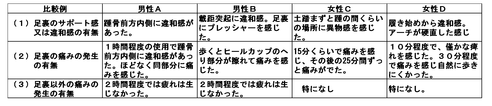
- the insoles of Example 3 and the insoles of Comparative Example were placed on the athletic shoes and worn, and the usability when walking the asphalt for about 2 hours was evaluated.
- the feeling of use is evaluated by (1) the presence or absence of support or discomfort in the sole of the foot when walking within 2 hours, (2) the presence or absence of pain in the sole of the foot, and (3) the presence or absence of pain other than the sole of the foot. did.
- the "support feeling” means whether or not there is a feeling that the sole of the foot is held by the insole, and the "uncomfortable feeling” means local or overall discomfort. Means.
- the insole of a shoe having a hardness of 63.5D in the support plate 3 has a feeling of support but may cause a slight discomfort, and may cause pain in the sole of the foot after long-term use. It was found that the insoles of shoes having a hardness of 72D in the support plate 3 tend to give a sense of discomfort, and even when used for a short time, pain in the sole of the foot may occur.
Landscapes
- Health & Medical Sciences (AREA)
- Public Health (AREA)
- General Health & Medical Sciences (AREA)
- Epidemiology (AREA)
- Life Sciences & Earth Sciences (AREA)
- Engineering & Computer Science (AREA)
- Heart & Thoracic Surgery (AREA)
- Nursing (AREA)
- Orthopedic Medicine & Surgery (AREA)
- Biomedical Technology (AREA)
- Vascular Medicine (AREA)
- Animal Behavior & Ethology (AREA)
- Veterinary Medicine (AREA)
- Wood Science & Technology (AREA)
- Materials Engineering (AREA)
- Chemical & Material Sciences (AREA)
- Footwear And Its Accessory, Manufacturing Method And Apparatuses (AREA)
Abstract
Description
特許文献1に記載の靴の中敷きは、足裏の略全体を配置させるシート部の上面側に、母趾球よりもやや踵側の中央部分に対向するように、中央凸部とその両側に中央凹部を設けている。また、特許文献1に記載の靴の中敷きは、シート部の下面側の略中央から踵に対応させる部分までを略覆い得るように装着させた硬質の支持プレートを備えている。この支持プレートには、シート部の一部を嵌合させる貫通孔が支持プレートの両側縁に略沿って2列形成されている。また、支持プレートには、2列の貫通孔の内側に、中敷きの長手方向に延びる凸条部が形成されている。
上記構成によって、特許文献1の中敷きは、足の骨格を好ましい位置に配置し、歩行時等の運動時における足や身体の歪みに基づく負担を軽減するという非常に優れた効果を奏している。
そこで、発明者は、関節の適切な噛み合いをより高度なレベルで、かつ、足の動きを徒に制限することなく自然に保持可能な靴の中敷きを開発した。
この構成によれば、シート部の中央後壁部のアーチ形状が支持プレートの中央後壁部の上面形状に支持され、シート部上面に配置される足に的確にアーチ形状を形成することが可能となる。
この構成によれば、外果の真下に位置する踵部及び/又はアーチ部の基端部すなわち立方骨の下方部分を外側から支持して足の骨格の崩れを防止することができる。
この構成によれば、支持プレートによる足への負担を軽減することが出来る。
この構成によれば、支持プレートによる足への負担をより軽減することが出来る。
この構成によれば、シート部及び支持プレートの中央後壁部により形成されるアーチ形状によって足に縦アーチ形状が形成されることにより乗りやすくなる踵部への体重を適切に受けつつ、足に掛かる体重のバランスを保たせ易くなる。
さらに、前記第1層と前記第2層は、アスカーゴム硬度計(C型)を用いた測定硬度とISO4662により計測した反発弾性率が以下に示す関係にあるのが好ましい。
測定硬度 前記第1層<前記第2層
反発弾性率 前記第1層<前記第2層
爪先部4は、足の指を配置させるように形成された部分である。
張り出し部5は、足の幅が左右に最も張り出す図3に示す中足骨50の先端部(すなわち母趾球から小趾球)を配置させるように形成された部分である。
アーチ部6は、図3に示す張り出し部5を除く中足骨50から外果61の直下までを配置させるように形成された部分である。
シート部2の外形は、全体として概ね足の平面視の外形に沿うように形成されている。
外側壁部9は、図3に示す主に第5中足骨55を配置させるように上方に突出するアーチ型に湾曲させかつ端部を上方に立ち上げた部分である。外側壁部9の下面側には、長手方向に間隔を空けて複数の突起12が形成されている。
中央後壁部10bは、略一定の厚さで、中央前壁部10aは中央後壁部10bよりもやや厚みを以って形成されている。
図1及び図4に示すように、シート部2の踵部7の下面側には、踵部7に掛かる体重を吸収する肉厚部13が形成されている。
具体的には、支持プレート3は、シート部2の各部に対応するアーチ部6’、アーチ部6’を構成する内側壁部8’、外側壁部9’、中央前壁部10a’、中央後壁部10b’及び踵部7’を有している。また、支持プレート3の踵部7’も、足の踵の側面を取り囲んで保持する立ち上がり部7w’を有している。
内側凸条部15は、図2に示すように、内側壁部8’を側面視した際に下端に表れるアーチ形状に略平行なアーチ状に形成されている。外側凸条部16は、図7に示すように、外側壁部9’を側面視した際に下端に表れるアーチ形状に略平行なアーチ状に形成されている。
支持プレート3の中央前壁部10a’は、シート部2と同形状すなわち略偏平形状に形成されている。支持プレート3の中央後壁部10b’は、全体として略一定の厚みで、その上面及び下面が、シート部2の中央後壁部10bの下面及び内側凸条部15及び外側凸条部16とほぼ同じ長手方向のアーチ形状を形成している。
開口部19は、踵部7’の内側7a’及び後方側7b’においては線Lに略平行に形成され、踵部7’の外側7c’において線Lから離間するようにやや内側に延び、更に先端側7d’の外側において徐々に斜めに反り上がる中央後壁部10b’に差し掛かって広がっている。
支持プレート3の外周縁、貫通孔18及び開口部19を形成しているエッジは、シート部2に馴染みやすいように面取りされている。
支持プレート3は、熱可塑性ポリウレタン(TPU)等の硬質樹脂により形成されている。支持プレート3の硬度は、アスカーゴム硬度計(D型)を用いた測定で40D以上72D未満、45D以上65D未満の硬度で形成されている。
即ち、シート部2及び支持プレート3の内側壁部8’の下端、外側壁部9’の下端、内側凸条部15、外側凸条部16及び中央後壁部10b’の上下面の略同じ湾曲の縦アーチ形状により、靴の中敷き1の縦アーチの弾性力がより高められる。また、内側凸条部15、外側凸条部16及び中央後壁部10b’のアーチ形状により、柔軟かつ確実に足の土踏まずの幅方向中央部分(内側縦アーチと外側縦アーチとの間)を縦アーチ形状に保持している。
また、シート部2の中央前壁部10aに形成された中央凸部14も含めて、足の裏に不要な隙間を形成しないで足の各骨及び関節を適切にホールドすることができる。
これらの作用が相互的に組み合わさることにより、多数の関節で連結された足の骨が、ずれたり歪んだりすることを防止して適切に組み上がった状態を保持し易くなり、歩行その他の運動時に、足の骨のずれに基づく姿勢の歪みの発生が防止されるという効果を奏する。
この構成によれば、足の回外(すなわち足が小指側のサイドを中心にひねろうとする動き)を防止することができるという効果を奏する。
さらに、前記第1層と前記第2層とは、アスカーゴム硬度計(C型)を用いた測定硬度及びISO4662:2009により計測した反発弾性率が以下に示す関係にあるのが好ましい。
測定硬度 前記第1層<前記第2層、かつ、
反発弾性率 前記第1層<前記第2層
より具体的には、アスカーゴム硬度計(C型)を用いて測定した硬度が23以上28以下であって、ISO4662:2009により計測した反発弾性率が47%以上53%以下であり、さらに好ましくは49%以上52%以下である樹脂を好適に用いることができる。
また、前記第1層は、ポリウレタン発泡樹脂層であってもよい。
エチレン酢酸ビニル共重合体(EVA)等の軟質合成樹脂により、アスカーゴム硬度計(C型)を用いた測定で硬度約55としたシート部2と、熱可塑性ポリウレタン(TPU)等の硬質樹脂により、アスカーゴム硬度計(D型)を用いた測定で40Dの支持プレート3とを備えた上記実施態様に示す靴の中敷きを作成した。
支持プレート3の硬度を、アスカーゴム硬度計(D型)を用いた測定で55Dとした以外は、実施例1と同様の靴の中敷きを作成した。
支持プレート3の硬度を、アスカーゴム硬度計(D型)を用いた測定で63.5Dとした以外は、実施例1と同様の靴の中敷きを作成した。
支持プレート3の硬度を、アスカーゴム硬度計(D型)を用いた測定で72D(比較例)とした以外は、実施例1と同様の靴の中敷きを作成した。
身長約172cm、体重75kgの成人男性A,身長約162cm、体重53kgの成人男性B、身長約160cm、体重52kgの成人女性C、身長約164cm、体重56kgの成人女性Dに、実施例1~実施例3の中敷き及び比較例の中敷きをそれぞれ運動靴に設置して着用させ、アスファルトを約2時間歩いた際の使用感を評価した。使用感は、2時間以内歩行時の(1)足裏のサポート感又は違和感の有無、(2)足裏の痛みの発生の有無、(3)足裏以外の痛みの発生の有無及びを評価した。なお、本実施例において、「サポート感」とは、足裏が中敷きによりホールド(保持)されている感覚があるか否かを意味し、「違和感」とは、局所的又は全体的な不快感を意味する。各評価結果を表1~4に示す。


支持プレート3の硬度が55Dの靴の中敷きは、違和感はなくサポート感が良好で、足裏の痛みが生じ難いことが分かった。また、足裏以外の痛みが生じ難かったことから、足裏の形状を良好に保持できていることがうかがえた。
支持プレート3の硬度が72Dの靴の中敷きは、違和感を与えやすく、短時間の使用でも足裏の痛みが生じることがあることが分かった。
2 シート部
3 支持プレート
4 爪先部
5 張り出し部
6 アーチ部
7 踵部
8 内側壁部
9 外側壁部
10 中央壁部
10a 中央前壁部
10b 中央後壁部
13 肉厚部(シート部の一部)
14 中央凸部
15 内側凸条部
16 外側凸条部
18 貫通孔
19 開口部
Claims (9)
- 足の指を配置させるように形成された爪先部、足の幅が左右に最も張り出す中足骨の先端部を配置させるように形成された張り出し部、中足骨から外果の直下までを配置させるように形成されたアーチ部、及び外果の直下とその後方の踵骨を配置させるように形成された踵部を有し靴の底面の全体に配置されるシート部と、
前記シート部の前記アーチ部及び踵部の下面に貼り合わされ、前記シート部よりも硬質の素材で形成された支持プレートとを備え、
前記シート部及び前記支持プレートは、前記アーチ部において、少なくとも第1中足骨を配置させるようにアーチ型に湾曲させかつ端部を上方に立ち上げた内側壁部と、少なくとも第5中足骨を配置させるようにアーチ型に湾曲させかつ端部を上方に立ち上げた外側壁部と、前記内側壁部と前記外側壁部との間に形成された中央壁部と、を有し、
前記支持プレートは、前記内側壁部と前記中央壁部との境上に形成された内側凸条部及び前記外側壁部と前記中央壁部との境上に形成された外側凸条部を有し、
前記支持プレートの前記内側壁部及び前記外側壁部のそれぞれに、前記支持プレートの長手方向に沿って複数の貫通孔が形成され、
前記内側凸条部と前記外側凸条部との間に位置する前記中央壁部の少なくとも上面は、前記支持プレートの長手方向にアーチを描くように湾曲している靴の中敷き。 - 前記シート部及び前記支持プレートは、外果の真下を位置させる踵部及び/又はアーチ部の基端部に側面から対向させるよう上方に突出した延出部を有している請求項1に記載の靴の中敷き。
- 前記支持プレートは、硬度40D以上72D未満で形成され、一定の厚さで前記シート部の下面形状に沿って配されている請求項1又は2に記載の靴の中敷き。
- 前記支持プレートは、硬度45D以上65D未満で形成され、一定の厚さで前記シート部の下面形状に沿って配されている請求項1又は2に記載の靴の中敷き。
- 前記支持プレートの踵部には、前記シート部の一部を嵌合させる開口部が形成されている請求項1から4のいずれか一項に記載の靴の中敷き。
- 前記シート部は、異なる硬度及び反発弾性率を有する少なくとも2層の発泡樹脂層を備え、
上面側の第1層及び前記第1層の下側に設けられた第2層は、エチレン酢酸ビニル共重合体を主成分とする反発弾性樹脂層を構成し、
前記第1層及び前記第2層において、アスカーゴム硬度計(C型)を用いた測定硬度とISO4662により計測した反発弾性率とが以下に示す関係にある請求項1から5のいずれか一項に記載の靴の中敷き。
測定硬度 前記第1層<前記第2層
反発弾性率 前記第1層<前記第2層 - 前記第2層のアスカーゴム硬度計(C型)を用いた測定硬度は、50以上60以下であって、前記第2層のISO4662により計測した反発弾性率は、55%以上65%以下である請求項6に記載の靴の中敷き。
- 前記第1層のアスカーゴム硬度計(C型)を用いた測定硬度は、23以上28以下であって、前記第1層のISO4662により計測した反発性は、47%以上53%以下である請求項6又は7に記載の靴の中敷き。
- 前記シート部は、異なる反発弾性率を有する少なくとも2層の発泡樹脂層を備え、
上面側の第1層は、ポリウレタン発泡樹脂層を構成し、
前記第1層の下側に設けられた第2層は、エチレン酢酸ビニル共重合体を主成分とする反発弾性樹脂層を構成し、
前記第2層のアスカーゴム硬度計(C型)を用いた測定硬度は、50以上60以下であって、前記第2層のISO4662により計測した反発弾性率は、55%以上65%以下である請求項1から5のいずれか一項に記載の靴の中敷き。
Priority Applications (8)
| Application Number | Priority Date | Filing Date | Title |
|---|---|---|---|
| JP2021517496A JP6991539B2 (ja) | 2019-10-30 | 2020-10-29 | 靴の中敷き |
| CA3144203A CA3144203C (en) | 2019-10-30 | 2020-10-29 | Shoe insole |
| US17/620,686 US20220264995A1 (en) | 2019-10-30 | 2020-10-29 | Shoe insole |
| EP20883547.0A EP3970549B1 (en) | 2019-10-30 | 2020-10-29 | Shoe insole |
| AU2020376694A AU2020376694B2 (en) | 2019-10-30 | 2020-10-29 | Shoe insole |
| ES20883547T ES3040648T3 (en) | 2019-10-30 | 2020-10-29 | Shoe insole |
| KR1020217041178A KR102626724B1 (ko) | 2019-10-30 | 2020-10-29 | 신발의 안창 |
| CN202080043899.9A CN113966184B (zh) | 2019-10-30 | 2020-10-29 | 鞋的鞋垫 |
Applications Claiming Priority (2)
| Application Number | Priority Date | Filing Date | Title |
|---|---|---|---|
| JP2019-197982 | 2019-10-30 | ||
| JP2019197982 | 2019-10-30 |
Publications (1)
| Publication Number | Publication Date |
|---|---|
| WO2021085574A1 true WO2021085574A1 (ja) | 2021-05-06 |
Family
ID=75715213
Family Applications (1)
| Application Number | Title | Priority Date | Filing Date |
|---|---|---|---|
| PCT/JP2020/040727 Ceased WO2021085574A1 (ja) | 2019-10-30 | 2020-10-29 | 靴の中敷き |
Country Status (9)
| Country | Link |
|---|---|
| US (1) | US20220264995A1 (ja) |
| EP (1) | EP3970549B1 (ja) |
| JP (1) | JP6991539B2 (ja) |
| KR (1) | KR102626724B1 (ja) |
| CN (1) | CN113966184B (ja) |
| AU (1) | AU2020376694B2 (ja) |
| CA (1) | CA3144203C (ja) |
| ES (1) | ES3040648T3 (ja) |
| WO (1) | WO2021085574A1 (ja) |
Families Citing this family (3)
| Publication number | Priority date | Publication date | Assignee | Title |
|---|---|---|---|---|
| USD978511S1 (en) * | 2020-11-23 | 2023-02-21 | Shenzhen Mudadinuo Technology Co., Ltd. | Insole |
| USD1079226S1 (en) * | 2022-12-26 | 2025-06-17 | Zhuangli Qin | Insole |
| USD1092026S1 (en) * | 2023-11-17 | 2025-09-09 | First Class Store LTD | Shoe insole |
Citations (8)
| Publication number | Priority date | Publication date | Assignee | Title |
|---|---|---|---|---|
| JPS61168301A (ja) * | 1984-08-24 | 1986-07-30 | ノ−スウエスト ポ−ダイアトリツク ラボラトリ−ズ インコ−ポレ−テツド | 機能強化回復用装置 |
| JPH0531606U (ja) * | 1991-10-07 | 1993-04-27 | 東燃化学株式会社 | 靴の中敷 |
| JPH0779805A (ja) * | 1993-09-17 | 1995-03-28 | Kobayashi Pharmaceut Co Ltd | 可撓性靴中敷 |
| JP2005160727A (ja) * | 2003-12-02 | 2005-06-23 | Madras Kk | シャンク |
| JP2010125100A (ja) * | 2008-11-28 | 2010-06-10 | Opti:Kk | 靴用中敷 |
| JP2011056296A (ja) * | 2010-12-17 | 2011-03-24 | Dymoco Systems:Kk | 中敷きパッド及びそれを装着した履物 |
| JP3167048U (ja) * | 2011-01-21 | 2011-03-31 | アシックス商事株式会社 | 中敷 |
| JP2015085134A (ja) | 2013-11-01 | 2015-05-07 | ウィニングワン株式会社 | 靴の中敷き |
Family Cites Families (26)
| Publication number | Priority date | Publication date | Assignee | Title |
|---|---|---|---|---|
| US4079526A (en) * | 1975-12-27 | 1978-03-21 | Tatsuo Fukuoka | Footwear |
| US4405445A (en) * | 1981-08-24 | 1983-09-20 | Ashland Oil, Inc. | Homogenization of water and reduced crude for catalytic cracking |
| US4586273A (en) * | 1983-12-28 | 1986-05-06 | Bernard Chapnick | Shoe insert construction |
| US5184409A (en) * | 1984-08-24 | 1993-02-09 | Northwest Podiatric Laboratory, Inc. | Orthotic insert and method of making of the same |
| US5282326A (en) * | 1991-07-09 | 1994-02-01 | Schering-Plough Healthcare Products, Inc. | Removeable innersole for footwear |
| US5625965A (en) * | 1993-10-27 | 1997-05-06 | Wolverine World Wide, Inc. | Stand easy shoe insert |
| JP3979765B2 (ja) * | 2000-05-15 | 2007-09-19 | 株式会社アシックス | 靴底の緩衝装置 |
| JP2002282012A (ja) * | 2001-03-27 | 2002-10-02 | Moon Star Co | 靴中敷および靴底の構造 |
| JP4033647B2 (ja) * | 2001-08-01 | 2008-01-16 | 美津濃株式会社 | 中敷 |
| US20040181971A1 (en) * | 2003-03-21 | 2004-09-23 | E-Z Gard Industries, Inc.. | Footbed |
| US20070028484A1 (en) * | 2005-08-04 | 2007-02-08 | Skechers U.S.A., Inc. Ii | Shoe bottom heel portion |
| US7958653B2 (en) * | 2006-09-21 | 2011-06-14 | Schering-Plough Healthcare Products, Inc. | Cushioned orthotic |
| KR100770564B1 (ko) * | 2007-05-07 | 2007-10-26 | (주) 디유티코리아 | 다탄성(多彈性) 신발 안창의 구조 |
| US9493623B2 (en) * | 2008-12-22 | 2016-11-15 | Asahi Kasei Chemicals Corporation | Crosslinkable and foamable composition, crosslinked foam, and shoe midsole comprising the same |
| JP4633850B1 (ja) * | 2009-10-08 | 2011-02-16 | 桃子 細野 | インソール |
| KR101075172B1 (ko) * | 2011-03-04 | 2011-10-19 | 주식회사 블랙야크 | 경도가 서로 다른 3조각의 판형 중창부재로 이루어진 신발중창 |
| JP5729558B2 (ja) * | 2011-05-25 | 2015-06-03 | 株式会社アサヒコーポレーション | 靴の中敷 |
| FR2980339B1 (fr) * | 2011-09-26 | 2015-01-30 | Salomon Sas | Chaussure a semelage ameliore |
| JP5836212B2 (ja) * | 2012-06-30 | 2015-12-24 | 株式会社アサヒコーポレーション | 靴底 |
| KR20140104207A (ko) * | 2013-02-20 | 2014-08-28 | 주식회사 네오메드 | 신발용 기능성 뒷굽 깔창 |
| US9565888B2 (en) * | 2013-03-04 | 2017-02-14 | Lfrj, Llc | Shoe insert and method for using same |
| JP5984152B2 (ja) * | 2014-09-11 | 2016-09-06 | 株式会社トータルヘルスケア | 靴中敷 |
| JP5858450B1 (ja) * | 2015-02-12 | 2016-02-10 | 山本 秀二 | 靴中敷き |
| JP3197788U (ja) * | 2015-03-18 | 2015-06-04 | 有限会社エーピーエフ | インソール |
| US10136698B2 (en) * | 2015-05-28 | 2018-11-27 | Implus Footcare, Llc | Shoe insole |
| JP3222296U (ja) * | 2019-05-10 | 2019-07-25 | 株式会社フィットジョイジャパン | 医療用短靴 |
-
2020
- 2020-10-29 JP JP2021517496A patent/JP6991539B2/ja active Active
- 2020-10-29 CN CN202080043899.9A patent/CN113966184B/zh active Active
- 2020-10-29 CA CA3144203A patent/CA3144203C/en active Active
- 2020-10-29 US US17/620,686 patent/US20220264995A1/en active Pending
- 2020-10-29 AU AU2020376694A patent/AU2020376694B2/en active Active
- 2020-10-29 EP EP20883547.0A patent/EP3970549B1/en active Active
- 2020-10-29 WO PCT/JP2020/040727 patent/WO2021085574A1/ja not_active Ceased
- 2020-10-29 ES ES20883547T patent/ES3040648T3/es active Active
- 2020-10-29 KR KR1020217041178A patent/KR102626724B1/ko active Active
Patent Citations (8)
| Publication number | Priority date | Publication date | Assignee | Title |
|---|---|---|---|---|
| JPS61168301A (ja) * | 1984-08-24 | 1986-07-30 | ノ−スウエスト ポ−ダイアトリツク ラボラトリ−ズ インコ−ポレ−テツド | 機能強化回復用装置 |
| JPH0531606U (ja) * | 1991-10-07 | 1993-04-27 | 東燃化学株式会社 | 靴の中敷 |
| JPH0779805A (ja) * | 1993-09-17 | 1995-03-28 | Kobayashi Pharmaceut Co Ltd | 可撓性靴中敷 |
| JP2005160727A (ja) * | 2003-12-02 | 2005-06-23 | Madras Kk | シャンク |
| JP2010125100A (ja) * | 2008-11-28 | 2010-06-10 | Opti:Kk | 靴用中敷 |
| JP2011056296A (ja) * | 2010-12-17 | 2011-03-24 | Dymoco Systems:Kk | 中敷きパッド及びそれを装着した履物 |
| JP3167048U (ja) * | 2011-01-21 | 2011-03-31 | アシックス商事株式会社 | 中敷 |
| JP2015085134A (ja) | 2013-11-01 | 2015-05-07 | ウィニングワン株式会社 | 靴の中敷き |
Non-Patent Citations (1)
| Title |
|---|
| See also references of EP3970549A4 |
Also Published As
| Publication number | Publication date |
|---|---|
| AU2020376694B2 (en) | 2024-02-29 |
| CA3144203A1 (en) | 2021-05-06 |
| EP3970549A1 (en) | 2022-03-23 |
| US20220264995A1 (en) | 2022-08-25 |
| ES3040648T3 (en) | 2025-11-03 |
| KR102626724B1 (ko) | 2024-01-18 |
| JPWO2021085574A1 (ja) | 2021-11-25 |
| CN113966184A (zh) | 2022-01-21 |
| AU2020376694A1 (en) | 2022-01-20 |
| EP3970549B1 (en) | 2025-09-03 |
| CN113966184B (zh) | 2023-07-11 |
| JP6991539B2 (ja) | 2022-01-12 |
| EP3970549A4 (en) | 2023-02-08 |
| CA3144203C (en) | 2024-04-02 |
| EP3970549C0 (en) | 2025-09-03 |
| KR20220010532A (ko) | 2022-01-25 |
Similar Documents
| Publication | Publication Date | Title |
|---|---|---|
| CA2339446C (en) | Custom orthotic foot support assembly | |
| AU2006280479B2 (en) | Shoe insole | |
| US9737111B2 (en) | Removable shoe insert for corrective sizing | |
| EP2367454B1 (en) | Article of footwear | |
| KR101746521B1 (ko) | 맞춤형 밸런스 유지용 패드가 구비된 신발깔창 | |
| JP5278714B2 (ja) | トレーニングに適した靴の靴底 | |
| US8776399B2 (en) | Shoe insole | |
| US20110099842A1 (en) | Motion control insole with muscle strengthening component | |
| US7041075B2 (en) | Orthotic foot devices for bare feet and methods for stabilizing feet | |
| CN101262791A (zh) | 用于鞋类的三平面支承系统 | |
| JP2016512131A (ja) | 履物のための中立姿勢方向付け中敷システム | |
| JP6991539B2 (ja) | 靴の中敷き | |
| JP2002282012A (ja) | 靴中敷および靴底の構造 | |
| CN108652125B (zh) | 一种全包裹式亚健康矫正鞋 | |
| US10349701B2 (en) | Footwear having a sole formed with a cavity receiving a highly viscous gel | |
| JP5970423B2 (ja) | 足底用パッド | |
| JPWO2017175424A1 (ja) | インソール及びそのインソールの形態を備えた靴 | |
| KR101007606B1 (ko) | 발바닥 압력 분산을 위한 여성용 구두 중창용 아대, 이를 가진 중창 및 구두 | |
| US20180343976A1 (en) | Integrated shoe support structure combining heel counter and shank | |
| JP2025135623A (ja) | 歩行矯正姿勢改善具 | |
| JP2022119600A (ja) | 履物 | |
| JP2004195019A (ja) | 履き物及びその製造方法 |
Legal Events
| Date | Code | Title | Description |
|---|---|---|---|
| ENP | Entry into the national phase |
Ref document number: 2021517496 Country of ref document: JP Kind code of ref document: A |
|
| 121 | Ep: the epo has been informed by wipo that ep was designated in this application |
Ref document number: 20883547 Country of ref document: EP Kind code of ref document: A1 |
|
| ENP | Entry into the national phase |
Ref document number: 20217041178 Country of ref document: KR Kind code of ref document: A |
|
| ENP | Entry into the national phase |
Ref document number: 3144203 Country of ref document: CA |
|
| ENP | Entry into the national phase |
Ref document number: 2020883547 Country of ref document: EP Effective date: 20211215 |
|
| ENP | Entry into the national phase |
Ref document number: 2020376694 Country of ref document: AU Date of ref document: 20201029 Kind code of ref document: A |
|
| NENP | Non-entry into the national phase |
Ref country code: DE |
|
| WWG | Wipo information: grant in national office |
Ref document number: 2020883547 Country of ref document: EP |