WO2021090041A1 - 燃料電池システム - Google Patents
燃料電池システム Download PDFInfo
- Publication number
- WO2021090041A1 WO2021090041A1 PCT/IB2019/001246 IB2019001246W WO2021090041A1 WO 2021090041 A1 WO2021090041 A1 WO 2021090041A1 IB 2019001246 W IB2019001246 W IB 2019001246W WO 2021090041 A1 WO2021090041 A1 WO 2021090041A1
- Authority
- WO
- WIPO (PCT)
- Prior art keywords
- fuel cell
- exhaust gas
- flow path
- cell system
- combustor
- Prior art date
- Legal status (The legal status is an assumption and is not a legal conclusion. Google has not performed a legal analysis and makes no representation as to the accuracy of the status listed.)
- Ceased
Links
Images




Classifications
-
- H—ELECTRICITY
- H01—ELECTRIC ELEMENTS
- H01M—PROCESSES OR MEANS, e.g. BATTERIES, FOR THE DIRECT CONVERSION OF CHEMICAL ENERGY INTO ELECTRICAL ENERGY
- H01M8/00—Fuel cells; Manufacture thereof
- H01M8/04—Auxiliary arrangements, e.g. for control of pressure or for circulation of fluids
- H01M8/04007—Auxiliary arrangements, e.g. for control of pressure or for circulation of fluids related to heat exchange
- H01M8/04014—Heat exchange using gaseous fluids; Heat exchange by combustion of reactants
- H01M8/04022—Heating by combustion
-
- H—ELECTRICITY
- H01—ELECTRIC ELEMENTS
- H01M—PROCESSES OR MEANS, e.g. BATTERIES, FOR THE DIRECT CONVERSION OF CHEMICAL ENERGY INTO ELECTRICAL ENERGY
- H01M8/00—Fuel cells; Manufacture thereof
- H01M8/06—Combination of fuel cells with means for production of reactants or for treatment of residues
- H01M8/0606—Combination of fuel cells with means for production of reactants or for treatment of residues with means for production of gaseous reactants
-
- H—ELECTRICITY
- H01—ELECTRIC ELEMENTS
- H01M—PROCESSES OR MEANS, e.g. BATTERIES, FOR THE DIRECT CONVERSION OF CHEMICAL ENERGY INTO ELECTRICAL ENERGY
- H01M8/00—Fuel cells; Manufacture thereof
- H01M8/06—Combination of fuel cells with means for production of reactants or for treatment of residues
- H01M8/0606—Combination of fuel cells with means for production of reactants or for treatment of residues with means for production of gaseous reactants
- H01M8/0612—Combination of fuel cells with means for production of reactants or for treatment of residues with means for production of gaseous reactants from carbon-containing material
- H01M8/0618—Reforming processes, e.g. autothermal, partial oxidation or steam reforming
-
- H—ELECTRICITY
- H01—ELECTRIC ELEMENTS
- H01M—PROCESSES OR MEANS, e.g. BATTERIES, FOR THE DIRECT CONVERSION OF CHEMICAL ENERGY INTO ELECTRICAL ENERGY
- H01M8/00—Fuel cells; Manufacture thereof
- H01M8/06—Combination of fuel cells with means for production of reactants or for treatment of residues
- H01M8/0662—Treatment of gaseous reactants or gaseous residues, e.g. cleaning
-
- H—ELECTRICITY
- H01—ELECTRIC ELEMENTS
- H01M—PROCESSES OR MEANS, e.g. BATTERIES, FOR THE DIRECT CONVERSION OF CHEMICAL ENERGY INTO ELECTRICAL ENERGY
- H01M8/00—Fuel cells; Manufacture thereof
- H01M8/10—Fuel cells with solid electrolytes
- H01M8/12—Fuel cells with solid electrolytes operating at high temperature, e.g. with stabilised ZrO2 electrolyte
- H01M2008/1293—Fuel cells with solid oxide electrolytes
-
- Y—GENERAL TAGGING OF NEW TECHNOLOGICAL DEVELOPMENTS; GENERAL TAGGING OF CROSS-SECTIONAL TECHNOLOGIES SPANNING OVER SEVERAL SECTIONS OF THE IPC; TECHNICAL SUBJECTS COVERED BY FORMER USPC CROSS-REFERENCE ART COLLECTIONS [XRACs] AND DIGESTS
- Y02—TECHNOLOGIES OR APPLICATIONS FOR MITIGATION OR ADAPTATION AGAINST CLIMATE CHANGE
- Y02E—REDUCTION OF GREENHOUSE GAS [GHG] EMISSIONS, RELATED TO ENERGY GENERATION, TRANSMISSION OR DISTRIBUTION
- Y02E60/00—Enabling technologies; Technologies with a potential or indirect contribution to GHG emissions mitigation
- Y02E60/30—Hydrogen technology
- Y02E60/50—Fuel cells
Definitions
- the present invention relates to a fuel cell system.
- JPH11-176461A discloses a fuel cell apparatus including a fuel cell that generates electricity using hydrogen supplied from a reformed gas stream and oxygen supplied from an oxidant stream.
- This fuel cell device uses a fuel reformer that supplies reformed gas obtained by reforming methanol to a reformed gas stream, a combustor that burns gas discharged from the fuel cell, and exhaust gas discharged from the combustor. It is further equipped with a heat exchanger that is used to heat the fuel reformer.
- These fuel reformers, combustors, and heat exchangers are connected to fuel cells and the like via various pipes. Since a large number of pipes are used in such a fuel cell device, there is a problem that the fuel cell device becomes large in size.
- an object of the present invention is to provide a fuel cell system having a compact configuration.
- the fuel cell system includes a fuel cell that generates power by receiving a working gas supply, a combustor that burns off gas discharged from the fuel cell, and a combustor that supplies the working gas to the fuel cell. It includes a heat exchange device that exchanges heat with exhaust gas from the fuel cell, and a manifold that is arranged between the fuel cell and the combustor and the heat exchange device.
- the manifold has an off-gas flow path that guides the off-gas discharged from the fuel cell to the combustor, and an exhaust gas flow path that guides the exhaust gas discharged from the combustor to the heat exchange device.
- FIG. 1 is a schematic configuration diagram of a fuel cell system according to an embodiment.
- FIG. 2A is a plan view of the fuel cell system according to the embodiment.
- FIG. 2B is a perspective view of the fuel cell system according to the embodiment.
- FIG. 3 is an exploded perspective view of the exhaust combustor.
- FIG. 4 is an exploded perspective view of the manifold connecting the fuel cell stack and the exhaust combustor.
- FIG. 5 is a diagram for explaining the inside of the manifold.
- FIG. 6 is a side view of the second catalyst combustor arranged in the manifold.
- FIG. 7 is a diagram showing a temperature change of the exhaust gas.
- FIG. 8 is a diagram showing a first modification of the fuel cell system of the present embodiment.
- FIG. 9 is a diagram showing a manifold of the fuel cell system according to the second modification of the present embodiment.
- FIG. 10 is a diagram showing a manifold of a fuel cell system according to a third modification of the present embodiment.
- FIG. 11 is a diagram showing a manifold of a fuel cell system according to a fourth modification of the present embodiment.
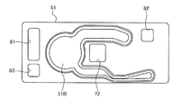
- FIG. 12 is a diagram showing a first plate of a manifold of a fuel cell system according to a fourth modification of the present embodiment.
- FIG. 1 is a schematic configuration diagram of a fuel cell system 100 according to an embodiment of the present invention.
- the fuel cell system 100 shown in FIG. 1 is, for example, an in-vehicle fuel cell system.
- the fuel cell system 100 includes a fuel cell stack 1 and a fuel tank 10 for storing raw fuel used for power generation of the fuel cell stack 1. Further, the fuel cell system 100 burns the reformer 20 that reforms the raw fuel into the anode gas, the air heat exchanger 30 that heats the air as the cathode gas, and the off gas discharged from the fuel cell stack 1. It includes an exhaust combustor 40 and a manifold 50 that guides anode gas, cathode gas, off gas, and the like to various devices.
- the fuel cell stack 1 is a laminate of fuel cells that generate electricity by receiving the supply of working gas (anode gas and cathode gas).
- the generated power of the fuel cell stack 1 is used to charge a battery or the like mounted on the hybrid vehicle.
- the fuel cell stack 1 is configured by stacking a plurality of fuel cells, and each fuel cell as a power source is, for example, a solid oxide fuel cell (SOFC).
- SOFC solid oxide fuel cell
- the fuel tank 10 stores raw fuel necessary for generating the anode gas supplied to the fuel cell stack 1 and generating the combustion gas used for warming up the system components and the like.
- the raw material fuel is, for example, a liquid fuel composed of water and ethanol (hydrous ethanol containing 40% by volume of ethanol).
- the liquid fuel is not limited to hydrous ethanol, and may be a liquid fuel containing gasoline, methanol, or the like.
- the raw fuel stored in the fuel tank 10 is supplied to the reformer 20 via the first injector 11, and is reformed into an anode gas in the reformer 20.
- the anode gas generated by the reformer 20 is supplied to the fuel cell stack 1 through the manifold 50.
- the air supplied to the air heat exchanger 30 via the air blower 31 is heated by the air heat exchanger 30.
- Air as the heated cathode gas is supplied to the fuel cell stack 1 through the manifold 50.
- the fuel cell stack 1 generates electricity by being supplied with an anode gas as a fuel gas and a cathode gas as an oxidant gas.
- the anode gas and the cathode gas that were not used during power generation are discharged from the fuel cell stack 1 as the anode off gas and the cathode off gas, respectively.
- These off-gass are supplied to the exhaust combustor 40 through the manifold 50 and burned in the exhaust combustor 40.
- the off-gas burned in the exhaust combustor 40 is supplied to the reformer 20 and the air heat exchanger 30 as high-temperature exhaust gas (combustion gas) through the manifold 50.
- the exhaust gas supplied to the reformer 20 is used for heat exchange with the reforming catalyst built in the reformer 20, and then discharged to the outside.
- the exhaust gas supplied to the air heat exchanger 30 is used for heat exchange with the cathode gas passing through the air heat exchanger 30, and then discharged to the outside.
- the reformer 20 and the air heat exchanger 30 are configured as heat exchange devices that exchange heat using the heat of the exhaust gas discharged from the exhaust gas combustor 40.
- the fuel cell system 100 further includes a fuel supply line L capable of directly supplying raw fuel to the exhaust combustor 40 in order to warm up the system components when the system is started.
- a second injector 12 is provided in the fuel supply line L, and the raw fuel injected from the second injector 12 is heated by the heater 13 and then supplied to the exhaust combustor 40.
- the exhaust combustor 40 burns the raw fuel heated by the heater 13.
- the combustion gas (exhaust gas) burned by the exhaust combustor 40 is used for warming up the reformer 20 and the air heat exchanger 30.
- FIG. 2A is a plan view of the fuel cell system according to the present embodiment
- FIG. 2B is a perspective view of the fuel cell system according to the present embodiment.
- FIG. 2B some description of system components such as the reformer is omitted.
- the manifold 50 is arranged between the fuel cell stack 1 and the heat exchange device such as the reformer 20 and the exhaust combustor 40.
- the reformer 20, the air heat exchanger 30, the exhaust combustor 40, and the manifold 50 are integrally configured. More specifically, the manifold 50 is configured as a substantially rectangular thin plate-shaped member, and the reformer 20, the air heat exchanger 30, and the exhaust combustor 40 are applied to the manifold end face on the side opposite to the fuel cell stack 1. It is connected so that it touches.
- the reformer 20, the air heat exchanger 30, and the exhaust combustor 40 are arranged side by side along the width direction of the fuel cell stack 1 while being connected to the manifold 50.
- the reformer 20 and the exhaust combustor 40 are located outside in the width direction, and the air heat exchanger 30 is located between the reformer 20 and the exhaust combustor 40.
- the manifold 50 is connected to the fuel cell stack 1 via the anode gas supply pipe 2, the cathode gas supply pipe 3, the anode off gas discharge pipe 4A, and the cathode off gas discharge pipe 4B.
- the anode gas supply pipe 2 connects the front surface of the fuel cell stack 1 and the manifold end face on the fuel cell stack side, and supplies the anode gas that has passed through the manifold 50 to the fuel cell stack 1.
- the cathode gas supply pipe 3 connects the front surface of the fuel cell stack 1 and the manifold end surface on the fuel cell stack side, and is arranged below the anode gas supply pipe 2.
- the cathode gas supply pipe 2 supplies the cathode gas that has passed through the manifold 50 to the fuel cell stack 1.
- the cathode off gas discharge pipe 4B connects the front surface of the fuel cell stack 1 and the manifold end face on the fuel cell stack side, and supplies the cathode off gas discharged from the fuel cell stack 1 to the manifold 50.
- the anode off-gas discharge pipe 4A connects the front surface of the fuel cell stack 1 and the manifold end surface on the fuel cell stack side, and is arranged below the cathode off-gas discharge pipe 4B.
- the anode off gas discharge pipe 4A supplies the anode off gas discharged from the fuel cell stack 1 to the manifold 50.
- the fuel cell stack 1 and the manifold 50 are connected by four pipes 2, 3, 4A, and 4B, but these pipes are omitted to connect the fuel cell.
- the stack 1 and the manifold 50 may be arranged adjacent to each other. When the fuel cell stack 1 and the manifold 50 are brought into contact with each other so as to be adjacent to each other, a plurality of gas passage holes for passing various gases are formed on the contact surfaces of both the fuel cell stack 1 and the manifold 50. It becomes.
- FIG. 3 is an exploded perspective view of the exhaust combustor 40.
- the exhaust combustor 40 includes a flow path portion 41 for flowing the anode-off gas and the cathode-off gas discharged from the fuel cell stack 1, a heater 42 provided at the downstream end of the flow path portion 41, and a second heater 42 provided at the downstream end of the heater 42. It includes a one-catalyst combustor 43 and an evaporator 44 provided on the downstream side of the first catalyst combustor 43.
- the flow path portion 41 is a gas passage whose upstream end is connected to the manifold 50 and supplies the off gas discharged from the manifold 50 to the heater 42.
- the flow path portion 41 is configured as a substantially U-shaped passage member that is linearly extended so as to be separated from the manifold 50 and then folded back toward the manifold 50.
- a heater 42 is arranged at the downstream end of the flow path portion 41.
- the heater 42 is, for example, a disk-shaped honeycomb structure, and is configured to heat the gas passing through the inside.
- a first catalyst combustor 43 is arranged at the downstream end of the heater 42.
- the first catalyst combustor 43 is a combustor composed of a carrier as a tubular honeycomb structure and a catalyst carried by the carrier.
- the first catalyst combustor 43 catalytically burns the anode-off gas and the cathode-off gas to generate high-temperature exhaust gas.
- the evaporator 44 is provided at the downstream end of the first catalyst combustor 43.
- the evaporator 44 is configured as a tubular member having a plurality of gas passage holes 44A, and its downstream end is connected to the end face of the manifold 50 by welding or the like.
- the exhaust gas generated by the first catalyst combustor 43 is supplied to the manifold 50 through the gas passage hole 44A of the evaporator 44.
- the evaporator 44 has an internal flow path 44B independent of the gas passage hole 44A, and supplies the raw fuel supplied from the fuel supply line L to the upstream side of the flow path portion 41 through the internal flow path 44B. .. That is, the evaporator 44 exchanges heat with the raw fuel passing through the internal flow path 44B when the high-temperature exhaust gas generated by the first catalyst combustor 43 passes through the gas passage hole 44A at the time of system startup or the like. The raw material and fuel are vaporized and the fuel gas is supplied to the flow path portion 41. Since the supply of raw fuel to the internal flow path 44B is stopped after the warm-up is completed, the evaporator 44 functions as a passage member that guides the exhaust gas discharged from the first catalyst combustor 43 to the manifold 50. ..
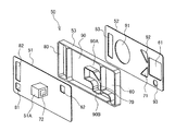
- FIG. 4 is an exploded perspective view of the manifold 50.
- the manifold 50 includes a main body 53 formed as a rectangular frame having openings at both ends, a first plate 51 covering the opening of the main body 53 on the fuel cell stack 1 side, and the main body 53. It has a second plate 52 that covers the opening on the exhaust combustor 40 side of the above.
- the main body 53 has a partition wall 53A that partitions the inside into a plurality of spaces.
- the plurality of spaces in the main body 53 and the first and second plates 51 and 52 arranged at both ends of the main body 53 form four flow paths through which various gases flow inside the manifold 50.
- an anode flow path 60, a cathode flow path 70, an off-gas flow path 80, and an exhaust gas flow path 90 are formed as flow paths through which various gases flow.
- the anode flow path 60 is a flow path for supplying the anode gas generated by the reformer 20 to the fuel cell stack 1.
- the anode flow path 60 is arranged at a position closer to the right end in the drawing in the width direction of the manifold 50.
- the second plate 52 is formed with an anode supply port 61 for supplying the anode gas to the anode flow path 60, and the first plate 51 transfers the anode gas that has passed through the anode flow path 60 to the fuel cell stack 1.
- An anode discharge port 62 for discharging is formed.
- the upstream end of the anode gas supply pipe 2 (see FIG. 2B) described above is connected to the anode discharge port 62.
- the cathode flow path 70 is a flow path for supplying the cathode gas heated by the air heat exchanger 30 to the fuel cell stack 1.
- the cathode flow path 70 is arranged at a substantially central position of the manifold 50.
- the second plate 52 is formed with a cathode supply port 71 for supplying the cathode gas to the cathode flow path 70, and the first plate 51 transfers the cathode gas that has passed through the cathode flow path 70 to the fuel cell stack 1.
- a cathode discharge port 72 for discharging is formed. The upstream end of the cathode gas supply pipe 3 (see FIG. 2B) described above is connected to the cathode discharge port 72.
- the off-gas flow path 80 is a flow path that merges the anode off-gas and the cathode gas discharged from the fuel cell stack 1 and leads them to the flow path portion 41 of the exhaust combustor 40.
- the off-gas flow path 80 is arranged at a position closer to the left end in the drawing in the width direction of the manifold 50.
- the first plate 51 is formed with an anode off gas supply port 81 for supplying the anode off gas to the off gas flow path 80 and a cathode off gas supply port 82 for supplying the cathode off gas to the off gas flow path 80.
- the downstream end of the anode off gas discharge pipe 4A described above is connected to the anode off gas supply port 81, and the downstream end of the cathode off gas discharge pipe 4B described above is connected to the cathode off gas supply port 82.
- the second plate 52 is formed with an off-gas discharge port 83 for discharging the off-gas that has passed through the off-gas flow path 80 to the exhaust combustor 40.
- the anode off-gas supply port 81 is formed below the cathode off-gas supply port 82.
- the off-gas flowing from the off-gas flow path 80 into the exhaust combustor 40 is burned by the first catalyst combustor 43 of the exhaust combustor 40, and the exhaust gas after combustion is exhaust gas flow path of the manifold 50 through the evaporator 44 of the exhaust combustor 40. It is supplied to 90.
- the exhaust gas flow path 90 is a flow path that guides the exhaust gas discharged from the exhaust gas combustor 40 to the reformer 20 and the air heat exchanger 30 as heat exchange devices.
- the exhaust gas flow path 90 is configured so that the downstream side branches into two flow paths. That is, one branch flow path of the exhaust gas flow path 90 is configured as a first exhaust gas flow path 90A that guides a part of the exhaust gas that has flowed into the manifold 50 from the exhaust gas flow path 40 to the air heat exchanger 30.
- the other branch flow path of the exhaust gas flow path 90 is configured as a second exhaust gas flow path 90B that guides the rest of the exhaust gas to the reformer 20.
- the exhaust gas flow path 90 is arranged so as to be located between the off-gas flow path 80 and the anode flow path 60 in the width direction of the manifold 50. Further, the first exhaust gas flow path 90A extends so as to cross above the cathode flow path 70, and the second exhaust gas flow path 90B extends so as to cross below the cathode flow path 70. As described above, the cathode flow path 70 is arranged so as to be located between the first exhaust gas flow path 90A and the second exhaust gas flow path 90B in the vertical direction orthogonal to the width direction of the manifold 50.
- the first plate 51 is formed with an exhaust gas supply port 91 for supplying exhaust gas to the exhaust gas flow path 90, which is an upstream portion of the first and second exhaust gas flow paths 90A and 90B. Further, the first plate 51 has a first exhaust gas supply port 92 that supplies the exhaust gas that has passed through the first exhaust gas flow path 90A to the air heat exchanger 30, and a reformer that supplies the exhaust gas that has passed through the second exhaust gas flow path 90B. A second exhaust gas discharge port 93 for supplying to 20 is formed.
- the fuel cell system 100 of the present embodiment a configuration for guiding gas such as off-gas and exhaust gas by using various flow paths formed in one manifold 50 is adopted, so that the manifold 50 is not used. Compared with the conventional method of inducing gas using a plurality of pipes, the fuel cell system 100 can be configured more compactly.
- off-gas is burned by the first catalyst combustor 43 of the exhaust combustor 40, and the exhaust gas after combustion is used as a heat source for a heat exchange device such as the reformer 20.
- a heat exchange device such as the reformer 20.
- the evaporator 44 or the like is arranged downstream of the first catalyst combustor 43 as in the fuel cell system 100, the exhaust gas temperature drops when the exhaust gas passes through the evaporator 44, and the heat exchange device and the heat exchange device. It is conceivable that the heat exchange efficiency of the
- the manifold 50 of the fuel cell system 100 is provided with a second catalyst combustor 54 that burns the exhaust gas that has flowed into the manifold 50 through the evaporator 44.
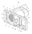
- FIG. 5 is a diagram for explaining the inside of the manifold 50.
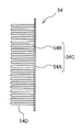
- FIG. 6 is a side view of the second catalyst combustor 54 arranged in the manifold 50.
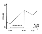
- FIG. 7 is a diagram showing a temperature change of the exhaust gas.
- the second catalyst combustor 54 has the first and second exhaust gas flow paths 90A.
- the exhaust gas flow path 90 is provided so as to vertically traverse the exhaust gas flow path 90.
- the second catalyst combustor 54 is arranged so as to be located between the exhaust gas supply port 91 formed on the second plate 52 and the first and second exhaust gas discharge ports 92 and 93.
- the second catalyst combustor 54 is composed of a carrier 54C composed of a substrate 54A and a plurality of flat plates 54B standing vertically from the surface of the substrate, and a catalyst 54D supported on the carrier 54C.
- the plurality of flat plates 54B are arranged so as to be parallel to the gas flow direction, and when the exhaust gas passes between the flat plates 54B, the fuel component remaining in the exhaust gas is present. Catalytic combustion.
- the off gas discharged from the fuel cell stack 1 is burned in the first catalyst combustor 43 of the exhaust combustor 40, so that the exhaust gas is discharged from the first catalyst combustor 43 (positions A to position).
- the exhaust gas temperature rises until it passes through B).
- the exhaust gas discharged from the first catalyst combustor 43 passes through the evaporator 44, so that the exhaust gas temperature drops due to heat exchange with the evaporator 44 until it passes through the evaporator 44.
- the exhaust gas that has passed through the evaporator 44 and has flowed into the manifold 50 passes through the second catalyst combustor 54 as shown by the arrow in FIG. Since the fuel component contained in the exhaust gas is burned while the exhaust gas passes through the second catalyst combustor 54, the exhaust gas temperature rises again from the position C passing through the second catalyst combustor 54 as shown in FIG. To do. As described above, according to the second catalyst combustor 54 of the manifold 50, it is possible to raise the exhaust gas temperature even when the exhaust gas temperature is lowered when passing through the evaporator 44.
- the fuel cell system 100 uses the fuel cell stack 1 that generates power by receiving the supply of working gases such as anode gas and cathode gas, the exhaust combustor 40 that burns the off gas discharged from the fuel cell stack 1, and the working gas as fuel. It is provided with a heat exchange device such as a reformer 20 that supplies heat to the battery stack 1 and exchanges heat with the exhaust gas from the exhaust gas combustor 40.
- the fuel cell system 100 further includes a manifold 50 arranged between the fuel cell stack 1 and heat exchange devices such as the exhaust combustor 40 and the reformer 20.
- the manifold 50 includes an off-gas flow path 80 that guides the off-gas discharged from the fuel cell stack 1 to the exhaust combustor 40, and an exhaust gas that guides the exhaust gas discharged from the exhaust combustor 40 to a heat exchange device such as the reformer 20. It has a flow path 90 and. More specifically, the exhaust gas flow path 90 includes a first exhaust gas flow path 90A that guides a part of the exhaust gas discharged from the exhaust gas combustor 40 to the air heat exchanger 30 (cathode heat exchanger), and the exhaust gas. It is provided with a second exhaust gas flow path 90B that guides the rest to the reformer 20.
- a plurality of flow paths such as the off-gas flow path 80 and the exhaust gas flow path 90 are formed in one manifold 50, and the manifold 50 is used as the fuel cell stack 1, the exhaust combustor 40, and heat exchange.
- the system configuration can be made more compact than when these devices are connected using a plurality of pipes.
- the exhaust combustor 40 of the fuel cell system 100 vaporizes the raw fuel by exchanging heat with the first catalyst combustor 43 that burns off-gas and the exhaust gas generated by the first catalyst combustor 43, and vaporizes the vaporized fuel. It includes an evaporator 44 that supplies the exhaust gas to the combustor 40.
- the exhaust gas flow path 90 of the manifold 50 is provided with a second catalyst combustor 54 that burns the exhaust gas that has flowed into the manifold 50 through the evaporator 44.
- the second catalyst combustor 54 provided in the manifold 50 is composed of a carrier 54C in which a plurality of flat plates 54B are arranged so as to be parallel to the gas flow direction, and a catalyst 54D supported on the carrier 54C.
- the fuel component contained in the exhaust gas can be more reliably catalyst-combusted using the catalyst 54D, and the exhaust gas temperature can be efficiently increased.
- the exhaust gas flow can be made uniform by passing the exhaust gas between the flat plates 54B of the second catalyst combustor 54. Therefore, it is possible to prevent temperature unevenness in the exhaust gas after passing through the second catalyst combustor 54.
- the manifold 50 further includes an anode flow path 60 for supplying the anode gas generated by the reformer 20 to the fuel cell stack 1.
- the off-gas flow path 80 is located on one end side of the manifold 50
- the anode flow path 60 is located on the other end side of the manifold 50
- the exhaust gas flow path 90 is the off-gas flow path 80 and the anode flow path 60. It is located between.
- the flow path length of the exhaust gas flow path 90 can be shortened.
- the distance from the second catalyst combustor 54 to the heat exchange device such as the reformer 20 is shortened, the temperature drop of the exhaust gas after passing through the second catalyst combustor 54 can be suppressed, and the heat exchange device can be used. It is possible to increase the heat exchange efficiency.
- the manifold 50 further includes a cathode flow path 70 for supplying the cathode gas heated by the air heat exchanger 30 to the fuel cell stack 1.
- the cathode flow path 70 is located between the first exhaust gas flow path 90A and the second exhaust gas flow path 90B in a direction orthogonal to the width direction of the manifold 50.
- FIG. 8 is a schematic configuration diagram showing a first modification of the fuel cell system 100 of the present embodiment.
- the description of some parts such as the reformer 20, the air heat exchanger 30, and the first plate 51 is omitted.
- the fuel cell system 100 has a supply pipe 14 for supplying raw fuel upstream of the second catalyst combustor (not shown) in the exhaust gas flow path 90 in the manifold 50. Further prepared.
- the supply pipe 14 is configured such that one end is connected to the fuel tank 10 (see FIG. 1) and the other end is inserted into the manifold 50. As described above, the supply pipe 14 is attached to the manifold 50 with the tip portion 14A inserted into the exhaust gas flow path 90 of the manifold 50.
- the tip 14A of the supply pipe 14 extends linearly in the exhaust gas flow path 90 in the vertical direction orthogonal to the width direction of the manifold 50, and a plurality of fuels extend in the tip 14A along the pipe extending direction.
- a supply port 14B is provided.
- the plurality of fuel supply ports 14B are provided so as to face the second catalyst combustor 54 toward the downstream side of the exhaust gas flow path 90, more specifically.
- the raw fuel of the fuel tank 10 is used as the fuel supply port 14B of the supply pipe 14. Is injected and supplied from the second catalyst combustor 54.
- the catalyst combustion in the second catalyst combustor 54 is promoted, and the high-temperature exhaust gas is sufficiently supplied to the heat exchange device such as the reformer 20. Can be supplied to.
- the tip portion 14A of the supply pipe 14 is linearly extended, but may have a shape other than the linear shape as long as fuel can be supplied into the exhaust gas flow path 90. .. Further, the number and orientation of the fuel supply ports 14B may be different from the above as long as the fuel supplied from the fuel supply port 14B can be burned by the second catalyst combustor 54. ..
- the fuel cell system 100 further includes a supply pipe 14 for supplying raw fuel upstream of the second catalyst combustor 54 in the manifold 50. According to such a configuration, raw fuel can be supplied from the supply pipe 14 to the second catalyst combustor 54 as needed, and high-temperature exhaust gas is sufficiently supplied to the heat exchange device such as the reformer 20. It becomes possible.
- the supply pipe 14 is attached to the manifold 50 with the tip 14A inserted into the manifold 50, and the tip 14A is provided with a plurality of fuel supply ports 14B along the pipe extension direction. There is.
- the fuel supply port 14B arranged along the pipe extension direction in this way, the fuel flow generated in the manifold 50 can be made uniform, and the fuel flow is generated by the second catalyst combustor 54.
- the temperature distribution of the exhaust gas to be produced can also be made uniform.
- the plurality of fuel supply ports 14B are arranged so that fuel is supplied toward the downstream side of the manifold 50. With this configuration, it is possible to supply a sufficient amount of fuel to the second catalyst combustor 54 located downstream of the supply pipe 14.
- FIG. 9 is an exploded perspective view of the manifold 50 of the fuel cell system 100 according to the second modification.
- the manifold 50 of the fuel cell system 100 according to the second modification is different from the first plate of the manifold shown in FIG. 4 in the configuration of the first plate 51.
- the portion of the first plate 51 facing the cathode flow path 70 is formed as a protruding portion 51A protruding toward the fuel cell stack 1.
- the protrusion 51A is configured so that the internal space communicates with the cathode flow path 70.
- the protrusion 51A is formed in a substantially rectangular parallelepiped tubular shape, and a cathode discharge port 72 for discharging the cathode gas that has passed through the cathode flow path 70 to the fuel cell stack 1 is formed on one side surface of the protrusion 51A. .. As described with reference to FIG. 2B, the upstream end of the cathode gas supply pipe 3 is connected to the cathode discharge port 72.
- the upstream end of the cathode gas supply pipe 3 is fixed to the cathode discharge port 72 by a fastening means such as bolt fastening, a fastening space for fixing the cathode gas supply pipe 3 is required around the cathode discharge port 72.
- a fastening space for fixing the cathode gas supply pipe 3 is required around the cathode discharge port 72.
- the second catalyst combustor 54 is arranged in the exhaust gas flow path 90 adjacent to the cathode flow path 70, when the cathode discharge port 72 is formed on the plate end surface of the first plate as shown in FIG. 4, the cathode gas is supplied. It may be difficult to secure a fastening space for fixing the pipe 3.
- the protrusion 51A is provided on the first plate 51 constituting the manifold end face, and the cathode discharge port 72 is formed on the protrusion 51A so that the position is different from the end face of the first plate 51.
- the cathode discharge port 72 can be arranged, and a fastening space for the cathode gas supply pipe 3 can be secured in the protruding portion 51A.
- FIG. 10 is a diagram showing the inside of the manifold 50 of the fuel cell system 100 according to the third modification.
- three second catalyst combustors 54 are provided in the exhaust gas flow path 90. That is, one second catalyst combustor 54-1 is provided in the first exhaust gas flow path 90A that guides the exhaust gas to the air heat exchanger 30, and two in the second exhaust gas flow path 90B that guides the exhaust gas to the reformer 20. Two second catalyst combustors 54-2 and 54.3 are provided. The two second catalyst combustors 54-2 and 54-3 are arranged so as to be adjacent to each other along the extending direction (gas flow direction) of the second exhaust gas flow path 90B.
- the second catalyst combustors 54-1, 54-2, and 54-3 have a carrier composed of a substrate and a plurality of flat plates vertically erected from the surface of the substrate, and a catalyst supported on the carrier. It is composed of and.
- the plurality of flat plates of the second catalyst combustor 54-1 are arranged so as to be parallel to the gas flow direction of the first exhaust gas flow path 90A, and the plurality of flat plates of the second catalyst combustors 54-2 and 54.3 are the first. 2 Arranged so as to be parallel to the gas flow direction of the exhaust gas flow path 90B.
- the second catalyst combustors 54-1, 54-2, and 54-3 are separately arranged in the first and second exhaust gas flow paths 90A and 90B, respectively. Even with such a configuration, the exhaust gas temperature that has dropped when passing through the evaporator 44 can be raised again by the second catalyst combustors 54-1, 54-2, and 54.3. Therefore, the temperature of the exhaust gas flowing into the heat exchange device such as the reformer 20 and the air heat exchanger 30 can be maintained at a high temperature, and the deterioration of the heat exchange efficiency in the heat exchange device can be suppressed. ..
- one first exhaust gas flow path 90A is used.
- the ventilation resistance of the first exhaust gas flow path 90A is second. It is made smaller than the ventilation resistance of the exhaust gas flow path 90B.
- the flow rates of the exhaust gases flowing through the first and second exhaust gas flow paths 90A and 90B can be adjusted, and the manifold It is possible to give the 50 a diversion function.
- one second catalyst combustor 54-1 is arranged in the first exhaust gas flow path 90A, and two second catalyst combustors 54-2 and 54-3 are arranged in the second exhaust gas flow path 90B.
- the number of second catalyst combustors arranged in each flow path can be arbitrarily set according to the exhaust gas flow rate required by a heat exchange device such as a reformer. Therefore, the number of second catalyst combustors arranged in the first exhaust gas flow path 90A may be larger than the number of second catalyst combustors arranged in the second exhaust gas flow path 90B. Further, the number of the second catalyst combustors arranged in the first exhaust gas flow path 90A and the number of the second catalyst combustors arranged in the second exhaust gas flow path 90B may be the same.
- the sizes of the second catalyst combustors arranged in the first and second exhaust gas flow paths 90A and 90B may be different. That is, the second catalyst combustor arranged in the second exhaust gas flow path 90B may be a catalyst combustor in which the second catalyst combustors 54-2 and 54-3 of FIG. 10 are integrated. In this case, the width of the second catalyst combustor arranged in the second exhaust gas flow path 90B is set to be about twice the width of the second catalyst combustor arranged in the first exhaust gas flow path 90A.
- FIG. 11 is a diagram showing the inside of the manifold 50 according to the fourth modification
- FIG. 12 is a diagram showing the first plate 51 of the manifold 50 according to the fourth modification.
- one second catalyst combustor 54-4, 54-5 is provided in each of the first and second exhaust gas flow paths 90A and 90B, respectively.
- the second catalyst combustors 54-4, 54-5 are fixed to the flow path in a state of being supported by the partition wall 53A of the main body 53.
- the second catalyst combustors 54-4, 54-5 are composed of a carrier 54E as a substantially cylindrical honeycomb structure and a catalyst 54F carried by the carrier 54E.
- the second catalyst combustors 54-4, 54-5 are arranged so that the extending direction of the internal passage in the carrier 54E is parallel to the gas flow direction in the flow path.
- the second catalyst combustors 54-4 and 54-5 are separately arranged in the first and second exhaust gas flow paths 90A and 90B, respectively. Even with such a configuration, the exhaust gas temperature that has dropped when passing through the evaporator 44 can be raised again by the second catalyst combustors 54-4 and 54-5. Therefore, the temperature of the exhaust gas flowing into the heat exchange device such as the reformer 20 and the air heat exchanger 30 can be maintained at a high temperature, and the deterioration of the heat exchange efficiency in the heat exchange device can be suppressed. ..
- the exhaust gas supplied to the air heat exchanger 30 is arranged in the first exhaust gas flow path 90A in order to make the flow rate of the exhaust gas supplied to the reformer 20 larger than the flow rate of the exhaust gas supplied to the reformer 20.
- the first exhaust gas flow path 90A is ventilated. The resistance is made smaller than the ventilation resistance of the second exhaust gas flow path 90B.
- the flow rates of the exhaust gases flowing through the first and second exhaust gas flow paths 90A and 90B can be adjusted. It is possible to provide the manifold 50 with a flow dividing function.
- the catalyst combustor 54-4, 54-5 When the shape of the second catalyst combustor 54-4, 54-5 is enlarged, when the second catalyst combustor 54-4, 54-5 is installed in the main body 53, the catalyst combustor 54-4, 54-5 A part may protrude outward from the main body 53. In such a case, as shown in FIG. 12, by forming a recess 51B along the exhaust gas flow path 90 in the first plate 51, the second catalyst combustors 54-4, 54-5 can be moved to the outside. Protrusion will be allowed.
- the size of the second catalyst combustors arranged in the first and second exhaust gas flow paths 90A and 90B is the same, and the number of the second catalyst combustors arranged in the second exhaust gas flow path 90B is the number of the first exhaust gas.
- the flow rate of the exhaust gas flowing through the first exhaust gas flow path 90A may be larger than the flow rate of the exhaust gas flowing through the second exhaust gas flow path 90B. Good.
- the second catalyst combustor 54-4 of the first exhaust gas flow path 90A is configured to be larger than the second catalyst combustor 54-5 of the second exhaust gas flow path 90B, but is arranged in each flow path.
- the size of the second catalyst combustor to be used can be arbitrarily set according to the exhaust gas flow rate required by a heat exchange device such as a reformer. Therefore, the second catalyst combustor arranged in the first exhaust gas flow path 90A may be configured to be larger than the second catalyst combustor arranged in the second exhaust gas flow path 90B, or the second exhaust gas flow path 90B. It may be the same size as the second catalyst combustor arranged in. Further, the first exhaust gas and the second exhaust gas flow paths 90A and 90B have the same passage cross-sectional area and different lengths in the gas flow direction of the second catalyst combustor to ventilate. The resistance may be adjusted to adjust the exhaust gas flow rate.
Landscapes
- Engineering & Computer Science (AREA)
- Chemical & Material Sciences (AREA)
- Life Sciences & Earth Sciences (AREA)
- Manufacturing & Machinery (AREA)
- Sustainable Development (AREA)
- Sustainable Energy (AREA)
- Chemical Kinetics & Catalysis (AREA)
- Electrochemistry (AREA)
- General Chemical & Material Sciences (AREA)
- Combustion & Propulsion (AREA)
- Fuel Cell (AREA)
Abstract
Description
次に、図8を参照して、上述した実施形態の第1変形例による燃料電池システム100について説明する。以下の変形例の説明においては、本実施形態と同じ機能を果たす構成等には同一の符号を用い、重複する説明を適宜省略する。
次に、図9を参照して、第2変形例による燃料電池システム100について説明する。図9は、第2変形例による燃料電池システム100のマニホールド50の分解斜視図である。
次に、図10を参照して、本実施形態の第3変形例による燃料電池システム100について説明する。図10は、第3変形例による燃料電池システム100のマニホールド50の内部の様子を示す図である。
次に、図11及び図12を参照して、本実施形態の第4変形例による燃料電池システム100のマニホールド50について説明する。図11は第4変形例によるマニホールド50の内部の様子を示す図であり、図12は第4変形例によるマニホールド50の第1プレート51を示す図である。
Claims (14)
- 作動ガスの供給を受けて発電する燃料電池を備える燃料電池システムであって、
前記燃料電池から排出されるオフガスを燃焼させる燃焼器と、
前記作動ガスを前記燃料電池に供給するとともに、前記燃焼器からの排ガスと熱交換を行う熱交換デバイスと、
前記燃料電池と、前記燃焼器及び前記熱交換デバイスとの間に配置されるマニホールドと、を備え、
前記マニホールドは、前記燃料電池から排出される前記オフガスを前記燃焼器へと導くオフガス流路と、前記燃焼器から排出される前記排ガスを前記熱交換デバイスへと導く排ガス流路と、を有する、
燃料電池システム。 - 請求項1に記載の燃料電池システムであって、
前記作動ガスは、燃料ガスとしてのアノードガスと、酸化剤ガスとしてのカソードガスとを含み、
前記熱交換デバイスは、前記排ガスの熱を用いて前記カソードガスを加熱するカソード熱交換器と、前記排ガスの熱を用いて原燃料を前記アノードガスに改質する改質器と、を備え、
前記排ガス流路は、前記排ガスの一部を前記カソード熱交換器へと導く第1排ガス流路と、前記排ガスの残りを前記改質器へと導く第2排ガス流路と、を備える、
燃料電池システム。 - 請求項2に記載の燃料電池システムであって、
前記燃焼器は、前記オフガスを燃焼させる第1触媒燃焼器と、前記第1触媒燃焼器で生成された前記排ガスと熱交換することで前記原燃料を気化させ、気化した燃料を前記燃焼器へと供給する蒸発器と、を備え、
前記排ガス流路には、前記蒸発器を通じて前記マニホールド内に流入した前記排ガスを燃焼させる第2触媒燃焼器が設けられる、
燃料電池システム。 - 請求項3に記載の燃料電池システムであって、
前記第2触媒燃焼器は、前記第1及び第2排ガス流路にそれぞれ別々に配置される、
燃料電池システム。 - 請求項4に記載の燃料電池システムであって、
前記第1排ガス流路に配置される前記第2触媒燃焼器の大きさと、前記第2排ガス流路に配置される前記第2触媒燃焼器の大きさは互いに異なる、
燃料電池システム。 - 請求項4又は5に記載の燃料電池システムであって、
前記第1排ガス流路に配置される前記第2触媒燃焼器の数と、前記第2排ガス流路に配置される前記第2触媒燃焼器の数は互いに異なる、
燃料電池システム。 - 請求項3から請求項6のいずれか一つに記載の燃料電池システムであって、
前記第2触媒燃焼器は、複数の平板がガス流れ方向と平行となるよう配置された担体と、前記担体に担持された触媒とから構成される、
燃料電池システム。 - 請求項3から請求項6のいずれか一つに記載の燃料電池システムであって、
前記第2触媒燃焼器は、筒状のハニカム構造体としての担体と、前記担体に担時された触媒とから構成される、
燃料電池システム。 - 請求項3から請求項8のいずれか一つに記載の燃料電池システムであって、
前記マニホールド内における前記第2触媒燃焼器に前記原燃料を供給するための供給配管をさらに備える、
燃料電池システム。 - 請求項9に記載の燃料電池システムであって、
前記供給配管は、先端部が前記マニホールド内に挿入された状態で当該マニホールドに取り付けられ、
前記先端部には、配管延設方向に沿って複数の燃料供給口が設けられる、
燃料電池システム。 - 請求項10に記載の燃料電池システムであって、
前記複数の燃料供給口は、前記排ガス流路の下流に向かって前記原燃料が供給されるように配置される、
燃料電池システム。 - 請求項2から請求項11のいずれか一つに記載の燃料電池システムであって、
前記マニホールドは、前記改質器で生成された前記アノードガスを前記燃料電池へと供給するためのアノード流路をさらに備え、
前記マニホールドの幅方向において、前記オフガス流路は前記マニホールドの一端側に位置し、前記アノード流路は前記マニホールドの他端側に位置し、前記排ガス流路は前記オフガス流路と前記アノード流路の間に位置する、
燃料電池システム。 - 請求項12に記載の燃料電池システムであって、
前記マニホールドは、前記カソード熱交換器で加熱された前記カソードガスを前記燃料電池へと供給するためのカソード流路をさらに備え、
前記幅方向と直交する方向において、前記カソード流路は前記第1排ガス流路と前記第2排ガス流路との間に位置する、
燃料電池システム。 - 請求項12に記載の燃料電池システムであって、
前記燃料電池が配置される側の前記マニホールドの端面において、前記カソード流路に対向する部位は当該燃料電池に向かって突出する突出部として形成されており、
前記突出部には、前記カソードガスを前記燃料電池に対して供給するための供給口が形成される、
燃料電池システム。
Priority Applications (5)
| Application Number | Priority Date | Filing Date | Title |
|---|---|---|---|
| EP19951931.5A EP4057399A4 (en) | 2019-11-07 | 2019-11-07 | FUEL CELL SYSTEM |
| CN201980101951.9A CN114730893B (zh) | 2019-11-07 | 2019-11-07 | 燃料电池系统 |
| PCT/IB2019/001246 WO2021090041A1 (ja) | 2019-11-07 | 2019-11-07 | 燃料電池システム |
| US17/774,949 US12015179B2 (en) | 2019-11-07 | 2019-11-07 | Fuel cell system |
| JP2021554790A JP7371697B2 (ja) | 2019-11-07 | 2019-11-07 | 燃料電池システム |
Applications Claiming Priority (1)
| Application Number | Priority Date | Filing Date | Title |
|---|---|---|---|
| PCT/IB2019/001246 WO2021090041A1 (ja) | 2019-11-07 | 2019-11-07 | 燃料電池システム |
Publications (1)
| Publication Number | Publication Date |
|---|---|
| WO2021090041A1 true WO2021090041A1 (ja) | 2021-05-14 |
Family
ID=75848288
Family Applications (1)
| Application Number | Title | Priority Date | Filing Date |
|---|---|---|---|
| PCT/IB2019/001246 Ceased WO2021090041A1 (ja) | 2019-11-07 | 2019-11-07 | 燃料電池システム |
Country Status (5)
| Country | Link |
|---|---|
| US (1) | US12015179B2 (ja) |
| EP (1) | EP4057399A4 (ja) |
| JP (1) | JP7371697B2 (ja) |
| CN (1) | CN114730893B (ja) |
| WO (1) | WO2021090041A1 (ja) |
Cited By (2)
| Publication number | Priority date | Publication date | Assignee | Title |
|---|---|---|---|---|
| WO2023117179A1 (de) * | 2021-12-21 | 2023-06-29 | Robert Bosch Gmbh | Brennstoffzellenvorrichtung |
| WO2023117180A1 (de) * | 2021-12-21 | 2023-06-29 | Robert Bosch Gmbh | Brennstoffzellenvorrichtung, sowie verfahren zur herstellung einer solchen brennstoffzellenvorrichtung |
Citations (3)
| Publication number | Priority date | Publication date | Assignee | Title |
|---|---|---|---|---|
| JPH11176461A (ja) | 1997-11-26 | 1999-07-02 | General Motors Corp <Gm> | 燃料セル装置 |
| JP2011222159A (ja) * | 2010-04-05 | 2011-11-04 | Ngk Spark Plug Co Ltd | 固体酸化物形燃料電池,および固体酸化物形燃料電池システム |
| JP2015207510A (ja) * | 2014-04-23 | 2015-11-19 | 本田技研工業株式会社 | 燃料電池モジュール |
Family Cites Families (17)
| Publication number | Priority date | Publication date | Assignee | Title |
|---|---|---|---|---|
| JPH07109772B2 (ja) | 1988-03-22 | 1995-11-22 | 石川島播磨重工業株式会社 | 内部マニホールド型燃料電池発電装置 |
| US6627339B2 (en) * | 2000-04-19 | 2003-09-30 | Delphi Technologies, Inc. | Fuel cell stack integrated with a waste energy recovery system |
| US6824906B2 (en) * | 2001-07-16 | 2004-11-30 | Modine Manufacturing Company | Fuel cell system incorporating and integrated cathode exhaust condenser and stack cooler |
| JP2004119357A (ja) * | 2002-09-30 | 2004-04-15 | Toto Ltd | 円筒構造固体酸化物形燃料電池システム用給気マニホールド |
| JP2005009427A (ja) * | 2003-06-20 | 2005-01-13 | Bosch Automotive Systems Corp | 排気ガス切換弁及び排気ガス後処理装置 |
| US7666539B2 (en) * | 2003-06-27 | 2010-02-23 | Ultracell Corporation | Heat efficient portable fuel cell systems |
| JP2005285694A (ja) * | 2004-03-30 | 2005-10-13 | Nissan Motor Co Ltd | 固体高分子型燃料電池および燃料電池システム |
| US7807313B2 (en) * | 2004-12-21 | 2010-10-05 | Ultracell Corporation | Compact fuel cell package |
| US7947407B2 (en) * | 2005-04-27 | 2011-05-24 | Lilliputian Systems, Inc. | Fuel cell apparatus having a small package size |
| JP2008269930A (ja) * | 2007-04-19 | 2008-11-06 | Matsushita Electric Ind Co Ltd | 燃料電池システム |
| JP2009078954A (ja) * | 2007-09-27 | 2009-04-16 | Fuji Electric Holdings Co Ltd | 改質装置 |
| JP5179520B2 (ja) * | 2008-01-29 | 2013-04-10 | 京セラ株式会社 | 燃料電池装置 |
| JP5494555B2 (ja) * | 2011-04-18 | 2014-05-14 | トヨタ自動車株式会社 | 燃料電池システム、および、燃料電池スタック |
| EP2950377B1 (en) * | 2013-03-25 | 2017-11-29 | Sumitomo Precision Products Co., Ltd. | Fuel cell |
| JP6531838B2 (ja) * | 2015-12-15 | 2019-06-19 | 日産自動車株式会社 | 燃料電池システム及び燃料電池システムの制御方法 |
| CA3008768C (en) * | 2015-12-15 | 2019-04-30 | Nissan Motor Co., Ltd. | Fuel cell system and controlling method of same |
| CN114342132B (zh) | 2019-09-04 | 2024-06-25 | 日产自动车株式会社 | 燃烧器和具备该燃烧器的燃料电池系统 |
-
2019
- 2019-11-07 WO PCT/IB2019/001246 patent/WO2021090041A1/ja not_active Ceased
- 2019-11-07 CN CN201980101951.9A patent/CN114730893B/zh active Active
- 2019-11-07 JP JP2021554790A patent/JP7371697B2/ja active Active
- 2019-11-07 EP EP19951931.5A patent/EP4057399A4/en not_active Withdrawn
- 2019-11-07 US US17/774,949 patent/US12015179B2/en active Active
Patent Citations (3)
| Publication number | Priority date | Publication date | Assignee | Title |
|---|---|---|---|---|
| JPH11176461A (ja) | 1997-11-26 | 1999-07-02 | General Motors Corp <Gm> | 燃料セル装置 |
| JP2011222159A (ja) * | 2010-04-05 | 2011-11-04 | Ngk Spark Plug Co Ltd | 固体酸化物形燃料電池,および固体酸化物形燃料電池システム |
| JP2015207510A (ja) * | 2014-04-23 | 2015-11-19 | 本田技研工業株式会社 | 燃料電池モジュール |
Non-Patent Citations (1)
| Title |
|---|
| See also references of EP4057399A4 |
Cited By (2)
| Publication number | Priority date | Publication date | Assignee | Title |
|---|---|---|---|---|
| WO2023117179A1 (de) * | 2021-12-21 | 2023-06-29 | Robert Bosch Gmbh | Brennstoffzellenvorrichtung |
| WO2023117180A1 (de) * | 2021-12-21 | 2023-06-29 | Robert Bosch Gmbh | Brennstoffzellenvorrichtung, sowie verfahren zur herstellung einer solchen brennstoffzellenvorrichtung |
Also Published As
| Publication number | Publication date |
|---|---|
| EP4057399A1 (en) | 2022-09-14 |
| JP7371697B2 (ja) | 2023-10-31 |
| US20220399552A1 (en) | 2022-12-15 |
| CN114730893B (zh) | 2024-06-25 |
| US12015179B2 (en) | 2024-06-18 |
| JPWO2021090041A1 (ja) | 2021-05-14 |
| EP4057399A4 (en) | 2024-08-21 |
| CN114730893A (zh) | 2022-07-08 |
Similar Documents
| Publication | Publication Date | Title |
|---|---|---|
| JP5512156B2 (ja) | 燃料電池 | |
| JP7263212B2 (ja) | 燃料電池モジュール及びこれに使用される流体供給装置 | |
| WO2009119616A1 (ja) | 改質器、セルスタック装置および燃料電池モジュールならびに燃料電池装置 | |
| JP5436196B2 (ja) | 発電装置 | |
| KR102437832B1 (ko) | 암모니아 기반 연료전지 시스템 모듈 | |
| JP6101781B2 (ja) | 燃料電池モジュール | |
| US11318436B2 (en) | Hydrogen reformer using exhaust gas | |
| JP5427568B2 (ja) | 発電装置 | |
| CN114447367B (zh) | 一种集成化热工部件、发电系统及固体氧化物燃料电池 | |
| JP7371697B2 (ja) | 燃料電池システム | |
| JP5481181B2 (ja) | 発電装置 | |
| JP5907751B2 (ja) | 固体酸化物形燃料電池 | |
| JP2020092096A (ja) | 固体酸化物形燃料電池装置 | |
| JP2016071961A (ja) | 固体酸化物形燃料電池装置 | |
| JP6077440B2 (ja) | 燃料電池モジュールおよび燃料電池装置 | |
| JP5376402B2 (ja) | 燃料電池モジュール | |
| JP6177359B2 (ja) | 固体酸化物形燃料電池 | |
| KR101387856B1 (ko) | 천연가스를 사용하는 고체산화물 연료전지용 판형 스팀리포머 | |
| JP7593874B2 (ja) | 燃料電池モジュール及び燃料電池装置 | |
| JP7753893B2 (ja) | 燃料電池装置 | |
| JP6315954B2 (ja) | 固体酸化物形燃料電池 | |
| JP2012219008A (ja) | 熱処理システム | |
| JP2012220176A (ja) | 熱処理システム | |
| WO2024143224A1 (ja) | 燃料電池モジュール及び燃料電池装置 | |
| JP6175010B2 (ja) | 燃料電池モジュール |
Legal Events
| Date | Code | Title | Description |
|---|---|---|---|
| 121 | Ep: the epo has been informed by wipo that ep was designated in this application |
Ref document number: 19951931 Country of ref document: EP Kind code of ref document: A1 |
|
| ENP | Entry into the national phase |
Ref document number: 2021554790 Country of ref document: JP Kind code of ref document: A |
|
| NENP | Non-entry into the national phase |
Ref country code: DE |
|
| ENP | Entry into the national phase |
Ref document number: 2019951931 Country of ref document: EP Effective date: 20220607 |
|
| WWW | Wipo information: withdrawn in national office |
Ref document number: 2019951931 Country of ref document: EP |