WO2021090732A1 - 通信装置、制御方法、およびプログラム - Google Patents
通信装置、制御方法、およびプログラム Download PDFInfo
- Publication number
- WO2021090732A1 WO2021090732A1 PCT/JP2020/040257 JP2020040257W WO2021090732A1 WO 2021090732 A1 WO2021090732 A1 WO 2021090732A1 JP 2020040257 W JP2020040257 W JP 2020040257W WO 2021090732 A1 WO2021090732 A1 WO 2021090732A1
- Authority
- WO
- WIPO (PCT)
- Prior art keywords
- communication device
- eht
- communication
- sta
- rus
- Prior art date
- Legal status (The legal status is an assumption and is not a legal conclusion. Google has not performed a legal analysis and makes no representation as to the accuracy of the status listed.)
- Ceased
Links
Images


Classifications
-
- H—ELECTRICITY
- H04—ELECTRIC COMMUNICATION TECHNIQUE
- H04W—WIRELESS COMMUNICATION NETWORKS
- H04W16/00—Network planning, e.g. coverage or traffic planning tools; Network deployment, e.g. resource partitioning or cells structures
- H04W16/02—Resource partitioning among network components, e.g. reuse partitioning
- H04W16/10—Dynamic resource partitioning
-
- H—ELECTRICITY
- H04—ELECTRIC COMMUNICATION TECHNIQUE
- H04W—WIRELESS COMMUNICATION NETWORKS
- H04W72/00—Local resource management
- H04W72/50—Allocation or scheduling criteria for wireless resources
- H04W72/53—Allocation or scheduling criteria for wireless resources based on regulatory allocation policies
-
- H—ELECTRICITY
- H04—ELECTRIC COMMUNICATION TECHNIQUE
- H04L—TRANSMISSION OF DIGITAL INFORMATION, e.g. TELEGRAPHIC COMMUNICATION
- H04L5/00—Arrangements affording multiple use of the transmission path
- H04L5/003—Arrangements for allocating sub-channels of the transmission path
- H04L5/0037—Inter-user or inter-terminal allocation
- H04L5/0041—Frequency-non-contiguous
-
- H—ELECTRICITY
- H04—ELECTRIC COMMUNICATION TECHNIQUE
- H04L—TRANSMISSION OF DIGITAL INFORMATION, e.g. TELEGRAPHIC COMMUNICATION
- H04L27/00—Modulated-carrier systems
- H04L27/26—Systems using multi-frequency codes
- H04L27/2601—Multicarrier modulation systems
- H04L27/2602—Signal structure
-
- H—ELECTRICITY
- H04—ELECTRIC COMMUNICATION TECHNIQUE
- H04L—TRANSMISSION OF DIGITAL INFORMATION, e.g. TELEGRAPHIC COMMUNICATION
- H04L1/00—Arrangements for detecting or preventing errors in the information received
- H04L1/0001—Systems modifying transmission characteristics according to link quality, e.g. power backoff
- H04L1/0023—Systems modifying transmission characteristics according to link quality, e.g. power backoff characterised by the signalling
- H04L1/0025—Transmission of mode-switching indication
-
- H—ELECTRICITY
- H04—ELECTRIC COMMUNICATION TECHNIQUE
- H04L—TRANSMISSION OF DIGITAL INFORMATION, e.g. TELEGRAPHIC COMMUNICATION
- H04L5/00—Arrangements affording multiple use of the transmission path
- H04L5/0001—Arrangements for dividing the transmission path
- H04L5/0003—Two-dimensional division
- H04L5/0005—Time-frequency
- H04L5/0007—Time-frequency the frequencies being orthogonal, e.g. OFDM(A) or DMT
-
- H—ELECTRICITY
- H04—ELECTRIC COMMUNICATION TECHNIQUE
- H04L—TRANSMISSION OF DIGITAL INFORMATION, e.g. TELEGRAPHIC COMMUNICATION
- H04L5/00—Arrangements affording multiple use of the transmission path
- H04L5/003—Arrangements for allocating sub-channels of the transmission path
- H04L5/0048—Allocation of pilot signals, i.e. of signals known to the receiver
-
- H—ELECTRICITY
- H04—ELECTRIC COMMUNICATION TECHNIQUE
- H04L—TRANSMISSION OF DIGITAL INFORMATION, e.g. TELEGRAPHIC COMMUNICATION
- H04L5/00—Arrangements affording multiple use of the transmission path
- H04L5/003—Arrangements for allocating sub-channels of the transmission path
- H04L5/0053—Allocation of signalling, i.e. of overhead other than pilot signals
-
- H—ELECTRICITY
- H04—ELECTRIC COMMUNICATION TECHNIQUE
- H04L—TRANSMISSION OF DIGITAL INFORMATION, e.g. TELEGRAPHIC COMMUNICATION
- H04L5/00—Arrangements affording multiple use of the transmission path
- H04L5/003—Arrangements for allocating sub-channels of the transmission path
- H04L5/0058—Allocation criteria
- H04L5/006—Quality of the received signal, e.g. BER, SNR, water filling
-
- H—ELECTRICITY
- H04—ELECTRIC COMMUNICATION TECHNIQUE
- H04L—TRANSMISSION OF DIGITAL INFORMATION, e.g. TELEGRAPHIC COMMUNICATION
- H04L5/00—Arrangements affording multiple use of the transmission path
- H04L5/0091—Signalling for the administration of the divided path, e.g. signalling of configuration information
- H04L5/0094—Indication of how sub-channels of the path are allocated
-
- H—ELECTRICITY
- H04—ELECTRIC COMMUNICATION TECHNIQUE
- H04W—WIRELESS COMMUNICATION NETWORKS
- H04W72/00—Local resource management
- H04W72/04—Wireless resource allocation
- H04W72/044—Wireless resource allocation based on the type of the allocated resource
- H04W72/0453—Resources in frequency domain, e.g. a carrier in FDMA
-
- H—ELECTRICITY
- H04—ELECTRIC COMMUNICATION TECHNIQUE
- H04W—WIRELESS COMMUNICATION NETWORKS
- H04W72/00—Local resource management
- H04W72/50—Allocation or scheduling criteria for wireless resources
- H04W72/52—Allocation or scheduling criteria for wireless resources based on load
-
- H—ELECTRICITY
- H04—ELECTRIC COMMUNICATION TECHNIQUE
- H04W—WIRELESS COMMUNICATION NETWORKS
- H04W72/00—Local resource management
- H04W72/50—Allocation or scheduling criteria for wireless resources
- H04W72/54—Allocation or scheduling criteria for wireless resources based on quality criteria
- H04W72/542—Allocation or scheduling criteria for wireless resources based on quality criteria using measured or perceived quality
-
- H—ELECTRICITY
- H04—ELECTRIC COMMUNICATION TECHNIQUE
- H04W—WIRELESS COMMUNICATION NETWORKS
- H04W74/00—Wireless channel access
- H04W74/04—Scheduled access
- H04W74/06—Scheduled access using polling
-
- H—ELECTRICITY
- H04—ELECTRIC COMMUNICATION TECHNIQUE
- H04W—WIRELESS COMMUNICATION NETWORKS
- H04W84/00—Network topologies
- H04W84/02—Hierarchically pre-organised networks, e.g. paging networks, cellular networks, WLAN [Wireless Local Area Network] or WLL [Wireless Local Loop]
- H04W84/10—Small scale networks; Flat hierarchical networks
- H04W84/12—WLAN [Wireless Local Area Networks]
Definitions
- the present invention relates to band allocation in wireless communication.
- the IEEE 802.11 series is known as a WLAN communication standard established by the IEEE (Institute of Electrical and Electronics Engineers, Institute of Electrical and Electronics Engineers).
- WLAN is an abbreviation for Wireless Local Area Network.
- IEEE802.11 series standard there are standards such as the IEEE802.11a / b / g / n / ac / ax standard.
- the IEEE is considering the formulation of the IEEE802.11be standard as a new standard for the IEEE802.11 series.
- Patent Document 1 discloses that the IEEE802.11ax standard executes wireless communication by OFDMA (Orthogonal Frequency Division Multiple Access).
- OFDMA Orthogonal Frequency Division Multiple Access
- the IEEE802.11ax standard realizes MU (Multi User, multi-user) communication in which one AP (access point) communicates with multiple STAs (stations) in parallel by executing wireless communication by OFDMA.
- the AP is a device having a role of constructing a network
- the STA is a device having a role of participating in the network constructed by the AP.
- MU communication by OFDMA parallel communication with a plurality of STAs is realized by the AP allocating a part of the frequency bandwidth (RU, resource unit) used for MU communication to each STA.
- one RU was assigned to one STA.
- some RUs cannot be assigned to the STAs, and the frequency band cannot be used efficiently.
- the communication quality of some frequency components contained in the RU assigned to the STA deteriorates, it is not possible to further allocate the RU having good communication quality to the STA, and the frequency band can be efficiently allocated. I could't use it.
- An object of the present invention is to improve the utilization efficiency of a frequency band by allowing a communication device to allocate a plurality of RUs to other communication devices.
- the communication device of the present invention includes L-STF (Legacy-Short Training Field), L-LTF (Legacy-Long Training Field) after the L-STF, and L- after the L-LTF.
- SIG Legacy-Signal
- EHT-SIG-A Extremely High Throughput-Signal-A
- An EHT-SIG-B containing information indicating that a plurality of RUs (Resource Units) are assigned to the device, and an EHT-STF (Extremely High Throwhput-Short Training Field) after the EHT-SIG-B.
- EHT-LTF Extremely High Throwhput-Long Training Field
- EHT MU Multi User PPDU (Physical Layer Generation Means) generated by the means to generate the Event Horizon Telescope Data. It also has a transmission means for transmitting the EHT MU PDU.
- the communication device of another aspect of the present invention includes a Frame control, a Duration after the Frame control, an RA (receiver addless) after the Duration, and a TA (transmitter addless) after the RA.
- TriggerFrame including a Communin Info after the TA and a User Invention that includes information indicating that a plurality of RUs (Resource Units) are assigned to one other communication device after the Common Info. It has a generation means for generating the above, and a transmission means for transmitting the Trigger Frame generated by the generation means.
- the present invention it is possible to improve the utilization efficiency of the frequency band by allowing the communication device to allocate a plurality of RUs to other communication devices.
- FIG. 5 is a flowchart showing a process executed by the communication device 102 when performing DL-OFDMA communication.
- FIG. 5 is a flowchart showing a process executed by the communication device 102 when performing UL-OFDMA communication.
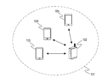
- FIG. 1 shows the configuration of a network in which the communication device 102 according to the present embodiment participates.
- the communication device 102 is an access point (AP, Access Point) having a role of constructing a network 101.
- the network 101 is a wireless network.
- the communication devices 103, 104, and 105 are stations (STA, Station) each having a role of participating in the network 101.
- Each communication device corresponds to the IEEE802.11be (EHT) standard, and can execute wireless communication conforming to the IEEE802.11be standard via the network 101.
- IEEE is an abbreviation for Institute of Electrical and Electronics Engineers.
- EHT is an abbreviation for Extremely High Throughput.
- EHT may be interpreted as an abbreviation for Extreme High Throughput.
- Each communication device can communicate in the frequency bands of 2.4 GHz band, 5 GHz band, and 6 GHz band. Also, each communication device can communicate using bandwidths of 20 MHz, 40 MHz, 80 MHz, 160 MHz, and
- the communication devices 102 to 105 can realize multi-user (MU, Multi User) communication in which signals of a plurality of users are multiplexed by executing OFDMA communication conforming to the IEEE802.11be standard.
- OFDMA communication is an abbreviation for Orthogonal Frequency Division Multiple Access (Orthogonal Frequency Division Multiple Access).
- RU Resource Unit
- the AP can communicate with a plurality of STAs in parallel.
- the communication devices 102 to 105 can realize MU communication by MU MIMO (Multi User Multi-Import and Multi-Uput) communication.
- the communication device 102 has a plurality of antennas, and by using the plurality of antennas, simultaneous communication with a plurality of STAs can be realized.
- the communication device 102 can transmit radio waves to a plurality of STAs at the same time by adjusting so that the radio waves transmitted to each of the communication devices 103 to 105 do not interfere with each other.
- the communication device 102 may realize MU communication by combining OFDMA communication and MU MIMO communication. That is, when the AP executes MU communication with a plurality of STAs, the AP may execute MU MIMO communication in a RU in which the number of subcarriers is equal to or greater than a certain threshold value. For example, when RU is assigned to a plurality of STAs, a RU having a subcarrier number smaller than 106 communicates with one STA, and a RU having a subcarrier number of 106 or more executes MU MIMO communication by a plurality of STAs. You may do so.
- the communication devices 103 to 105 need to acquire information regarding the allocation of RU to each STA. Therefore, the communication device 102 notifies the communication devices 103 to 105 of the allocation of the RU used in the data communication to each STA by using the PHY frame.
- the communication device 102 of the present embodiment can allocate two or more RUs per STA.
- the assigned RU may be two or more RUs having continuous frequency components, or two or more RUs having discontinuous frequency components.
- the communication device 102 when the communication device 102 communicates with the communication devices 103 to 105, by assigning two or more RUs only to the communication device 103, data can be preferentially communicated with the communication device 103.
- the AP can secure a wide frequency band for communication with the STA and can preferentially communicate with the STA.
- STA may not be assigned to some RUs depending on how the frequency band is divided. For example, when the AP communicates with three STAs and the frequency band is divided into four, the STA is not assigned to one RU. However, as in the communication device 102 of the present embodiment, by allocating a plurality of RUs to one STA, there is also a wasteful RU when only one RU is assigned to one STA. You will be able to utilize it.
- the communication device 102 communicates when the communication quality of some frequency components included in the RU assigned to the communication device 103 deteriorates due to the movement of at least one of the communication devices 102 and 103 or the passage of time.
- Multiple discontinuous RUs of good quality may be assigned.
- the communication device 102 allocates the RU having the number of subcarriers of 52 to the communication device 103, two RUs having the number of non-adjacent subcarriers of 26 may be assigned.
- the AP allocates two or more RUs that are not adjacent to one STA, so that even if the communication quality of the adjacent RUs is not good, a wide frequency band is secured to communicate with the STA. It can be carried out.
- the communication devices 102 to 105 are said to correspond to the IEEE802.11be standard, but in addition to this, they may correspond to at least one of the legacy standards which are the standards prior to the IEEE802.11be standard.
- the legacy standard is the IEEE802.11a / b / g / n / ac / ax standard.
- other communication standards such as Bluetooth (registered trademark), NFC, UWB, ZigBee, and MBOA may be supported.
- UWB is an abbreviation for Ultra Wide Band
- MBOA is an abbreviation for Multi Band OFDM Alliance.
- OFDM is an abbreviation for Orthogonal Frequency Division Multiplexing.
- NFC is an abbreviation for Near Field Communication.
- UWB includes wireless USB, wireless 1394, WiNET and the like. Further, it may correspond to a communication standard of wired communication such as a wired LAN.
- the communication device 102 include, but are not limited to, a wireless LAN router and a PC.
- the communication device 102 may be any communication device capable of performing MU communication with another communication device.
- the communication device 102 may be an information processing device such as a wireless chip capable of executing wireless communication conforming to the IEEE802.11be standard.
- Specific examples of the communication devices 103 to 105 include, but are not limited to, cameras, tablets, smartphones, PCs, mobile phones, video cameras, and the like.
- the communication devices 103 to 105 may be any communication device capable of executing MU communication with other communication devices.
- the communication devices 103 to 105 may be information processing devices such as a wireless chip capable of executing wireless communication conforming to the IEEE802.11be standard.
- the network of FIG. 1 is a network composed of one AP and three STAs, but the number of APs and STAs is not limited to this.
- An information processing device such as a wireless chip has an antenna for transmitting the generated signal.
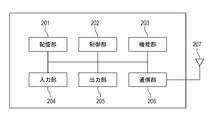
- FIG. 2 shows the hardware configuration of the communication device 102 in this embodiment.
- the communication device 102 includes a storage unit 201, a control unit 202, a function unit 203, an input unit 204, an output unit 205, a communication unit 206, and an antenna 207.
- the storage unit 201 is composed of one or more memories such as ROM and RAM, and stores various information such as a computer program for performing various operations described later and communication parameters for wireless communication.
- ROM is an abbreviation for Read Only Memory
- RAM is an abbreviation for Random Access Memory.
- storage media such as flexible disks, hard disks, optical disks, magneto-optical disks, CD-ROMs, CD-Rs, magnetic tapes, non-volatile memory cards, and DVDs. May be used. Further, the storage unit 201 may include a plurality of memories and the like.
- the control unit 202 is composed of one or more processors such as a CPU and an MPU, and controls the entire communication device 102 by executing a computer program stored in the storage unit 201.
- the control unit 202 may control the entire communication device 102 in cooperation with the computer program stored in the storage unit 201 and the OS (Operating System).
- the control unit 202 generates data and signals to be transmitted in communication with other communication devices.
- the CPU is an abbreviation for Central Processing Unit
- MPU is an abbreviation for Micro Processing Unit.
- the control unit 202 may include a plurality of processors such as a multi-core processor, and the plurality of processors may control the entire communication device 102.
- control unit 202 controls the function unit 203 to execute predetermined processing such as wireless communication, imaging, printing, and projection.
- the functional unit 203 is hardware for the communication device 102 to execute a predetermined process.
- the input unit 204 accepts various operations from the user.
- the output unit 205 outputs various outputs to the user via the monitor screen and the speaker.
- the output by the output unit 205 may be a display on the monitor screen, an audio output by the speaker, a vibration output, or the like.
- both the input unit 204 and the output unit 205 may be realized by one module like a touch panel.
- the input unit 204 and the output unit 205 may be integrated with the communication device 102 or may be separate from each other.
- the communication unit 206 controls wireless communication in accordance with the IEEE802.11be standard. Further, the communication unit 206 may control wireless communication conforming to other IEEE802.11 series standards in addition to the IEEE802.11be standard, or control wired communication such as a wired LAN. The communication unit 206 controls the antenna 207 to transmit and receive signals for wireless communication generated by the control unit 202. If the communication device 102 supports the NFC standard, the Bluetooth standard, or the like in addition to the IEEE802.11be standard, wireless communication control conforming to these communication standards may be performed. Further, when the communication device 102 can execute wireless communication conforming to a plurality of communication standards, the communication unit 206 and the antenna 207 corresponding to the respective communication standards may be individually provided.
- the communication device 102 communicates data such as image data, document data, and video data with the communication devices 103 to 105 via the communication unit 206.
- the antenna 207 may be configured as a separate body from the communication unit 206, or may be configured as one module together with the communication unit 206.
- the communication devices 103 to 105 have the same hardware configuration as the communication device 102.
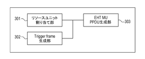
- FIG. 3 shows the functional block configuration of the communication device 102 in this embodiment.
- the communication device 102 includes a resource unit allocation unit 301, a Tiger Frame generation unit 302, and an EHT MU PPDU generation unit 303.
- the resource unit allocation unit 301 is a block that allocates RU to each STA when the communication device 102 performs OFDMA communication with a plurality of STAs.
- the resource unit allocation unit 301 determines the RU to be allocated to each STA based on the communication quality of each RU, the amount of data buffered to communicate with each STA, and the like.
- the Tiger Frame generation unit 302 is a block that generates a Trigger Frame transmitted by the communication device 102 when performing UL (uplink, Up Link) communication for transmitting data from the STA to the AP.
- the Trigger Frame will be described with reference to FIG. 5 described later.
- the EHT MU PPDU generation unit 303 is a block that generates an EHTMU PPDU transmitted by the communication device 102 when performing DL (Downlink, Downlink) communication for transmitting data from the AP to the STA.
- PDU is an abbreviation for Physical Layer (PHY) Protocol Data Unit.
- the EHT MUPPDU will be described with reference to FIG. 4 described later.
- Both the Trigger Frame and the EHT MU PPDU are frames that include information regarding the allocation of RU to STAs that perform MU communication.
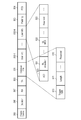
- FIG. 4 shows an example of the frame format of the EHT MU PPDU transmitted by the communication device 102.
- EHT MU PPDU is a frame format used by a communication device conforming to the IEEE802.11be standard when executing DL MU communication. This frame is composed of L-STF401, L-LTF402, L-SIG403, RL-SIG404, EHT-SIG-A405, EHT-SIG-B406, EHT-STF407, and EHT-LTF408 from the beginning. Further, EHT-LTF408 is configured to be followed by PSDU (PHY service data unit) 409. Data addressed to each STA is stored in the PSDU 409. The order of each field of EHT MU PPDU is not limited to this.
- PSDU PHY service data unit
- STF is an abbreviation for Short Training Field
- LTF is an abbreviation for Long Training Field
- SIG is an abbreviation for Signal.
- L- is an abbreviation for Legacy
- L-STF is an abbreviation for Legacy Short Training Field
- EHT- is an abbreviation for Extreme High High Throughput
- EHT-STF is an abbreviation for Extreme High High Throughput Training Field
- RL-SIG is an abbreviation for Repeated Legacy Signal.
- L-STF401, L-LTF402, and L-SIG403 are backwards compatible with the IEEE802.11a / b / g / n / ac / ax standard, which are legacy standards developed prior to the IEEE802.11be standard, respectively. There is. That is, L-STF401, L-LTF402, and L-SIG403 are legacy fields that can be decoded by a communication device corresponding to the IEEE802.11 series standard before IEEE802.11ax.
- L-STF401 is used for wireless packet signal detection, automatic gain control (AGC, Automatic Gain Control), timing detection, and the like.
- L-LTF402 is used for high-precision frequency / time synchronization and acquisition of propagation channel information (CSI, Channel State Information).
- the L-SIG 403 is used to transmit control information including communication rate and lens information.
- the RL-SIG404 may be omitted.
- EHT-SIG-A405, EHT-SIG-B406, EHT-STF407, and EHT-LTF408 are EHT fields that can be decoded by a communication device corresponding to the IEEE802.11be standard.
- EHT-SIG-B406 is composed of common field 410, user fields 411 to 419, and padding 440.
- the user field is included for the number of STAs to which the communication device 102 allocates the RU.
- padding 440 is a field for adjusting the size of EHT-SIG-B, and may be omitted.
- the name of the COMMON field may be the COMMON info field.
- the name of the User field may be the User info field.
- the common field 410 contains information common to all STAs to which the communication device 102 transmits the EHT MU PPDU.
- the subfields included in the common field 410 are shown in Table 1.
- the correspondence between N and each bandwidth (20 MHz, 40 MHz, 80 MHz, 160 MHz, and 320 MHz) is as shown in Table 1.
- the case of 80 + 80 MHz is a case of using two bandwidths of 80 MHz.
- the case of 160 + 160 MHz is a case of using two bandwidths of 160 MHz.
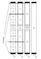
- FIG. 601 to 604 of FIG. 6 show how to divide the RUs, respectively.
- FIG. 6 shows a case where RU with 26 subcarriers is assigned to each STA.
- OFDMA communication can be performed simultaneously with nine STAs per 20 MHz of the frequency bandwidth used.
- Null Subcarriers are subcarriers for which RU is not set. That is, the frequency components of the second RU from the left and the third RU are not continuous.
- a Null Subcarrier may exist between the RU of the 4th circle from the left and the RU of the 5th circle.
- a Null Subcarrier may exist between the 5th RU and the 6th RU from the left.
- 602 shows a case where RU with 52 subcarriers is assigned to some STAs. OFDMA communication can be performed simultaneously with five STAs per 20 MHz of the frequency bandwidth used.
- RUs having 52 subcarriers are assigned to four STAs, and RUs having 26 subcarriers are assigned to one STA.
- the RU having 26 subcarriers is treated as one RU by combining the RUs having 13 subcarriers located in the center of 602. Since the central RU contains a direct current (DC) tone, the frequency components are not continuous in the RU, but they are treated as one RU.
- DC direct current
- the allocation method including four RUs with 52 subcarriers is shown, but the present invention is not limited to this, and RUs may be allocated so as to include 1 to 3 RUs with 52 subcarriers. In this case, the remaining RU has 26 subcarriers.
- the frequency components of the first RU and the second RU from the left are not continuous.
- the fourth RU and the fifth RU do not have continuous frequency components.
- the Null Subcarrier may be present at least between the second RU and the third RU from the left and between the third RU and the fourth RU.
- the frequency band is divided by the division method shown in 602.
- the central RU number of subcarriers 26
- the frequency band cannot be used efficiently because of the RU that is not assigned to the STA.
- the communication device 102 can assign a plurality of RUs to one STA, when one RU is assigned to one STA, the RUs to which the STAs have not been assigned are also assigned to the STAs. And the bandwidth utilization efficiency can be improved.
- 603 shows a case where RU with 106 subcarriers is assigned to some STAs. OFDMA communication can be performed simultaneously with three STAs per 20 MHz of the frequency bandwidth used. In 603, two STAs are assigned RUs with 106 subcarriers, and one STA is assigned RUs with 26 subcarriers. Alternatively, RUs having 106 subcarriers may be assigned to a plurality of STAs, and MU-MIMO communication may be performed with the plurality of STAs. In 604, a method of allocating two RUs having 106 subcarriers is shown, but the present invention is not limited to this, and RUs may be allocated so as to include one RU having 106 subcarriers.
- the remaining RUs in this case are allocated to include at least one of the 52 subcarrier RUs or the 26 subcarriers RUs so that the total number of subcarriers is 132. Further, the STA may not be assigned to the RU having the central number of subcarriers 26. Also in this case, the Null Subcarrier may be present at least between the first RU and the second RU from the left and between the second RU and the third RU.
- 604 shows a case where a RU having 242 subcarriers is assigned to one STA. It is possible to perform OFDMA communication with one STA per 20 MHz of the frequency bandwidth used. Alternatively, RUs having 242 subcarriers may be assigned to a plurality of STAs, and MU-MIMO communication may be performed with the plurality of STAs.
- the RU Allocation subfield 420 indicates how to allocate the RU as shown by 601 to 604 in FIG. 6 for every 8 bits. For example, when 80 MHz is used as the bandwidth, the first 8 bits may indicate an allocation of RU such as 601 and the latter 8 bits may indicate an allocation of RU such as 603. Further, when MIMO communication is performed in a RU having 106 or more subcarriers, the number of STAs and MIMO communication in the RU are also indicated in the RU allocation subfield 420.
- Tail 421 is a field used to adjust the size of the Common field 410.
- User fields 411 to 419 are fields that include information about STAs that perform MU communication.
- the User field is included in the EHT MU PPDU as many as the number of RUs indicated by the RU allocation subfield 420. For example, if the frequency band used by the communication device 102 is 20 MHz and the RU allocation subfield 420 indicates a RU allocation as shown in 601 of FIG. 6, the EHT MU PPDU includes nine User fields. It should be noted that this does not apply when it is indicated in the RU allocation subfield 420 that MIMO communication is performed in a RU having 106 or more subcarriers.
- the User field includes a STA-ID (Station-Identification) subfield 430 and an MCS (Modulation and Coding Scheme) subfield 431.
- the STA-ID subfield 430 contains STA identification information. Specifically, the identification information included in the STA-ID is a part of the AID (association identifier) which is an identifier assigned to the STA by the AP when the STA associates with the AP (communication device 102).
- AID association identifier
- Which STA of the User fields 411 to 419 corresponds to each RU indicated by the RU allocation subfield 420 is determined by the order of the User fields. Specifically, in the RU allocation shown in FIG. 6, the STAs are assigned to the STAs indicated by STA-ID 430 in the first User field in order from the leftmost RU. That is, the STA shown in the second User field is assigned the second RU from the left.
- the number of STAs indicated in the RU allocation subfield 420 is assigned.
- the information included in the RU Allocation subfield indicates the number of STAs that will be assigned to the RUs used for MIMO communication, in addition to how to divide the RUs. It will be shown whether it will be done. For example, consider a case where the RU Allocation subfield indicates how to divide RUs such as 603 and the number of STAs that perform MIMO communication in the leftmost RU is three. In this case, among the User fields following the RU Allocation subfield, the three STAs shown in the third to third User fields are the STAs that perform MIMO communication in the RU.
- the STA shown in the fourth User field communicates in the central RU having 26 subcarriers.
- the RU Allocation subfield indicates that the number of STAs that perform MIMO communication in the third RU is two
- the STAs shown in the fifth and sixth User fields are the RUs. MIMO communication will be performed in.
- the communication device 102 assigns RUs to STAs, a plurality of RUs that perform MIMO communication may be assigned to the same STA.
- the communication device 102 may combine a RU that performs MIMO communication and a RU that does not perform MIMO communication and assign them to the same STA.
- the MCS subfield 431 stores information indicating the modulation method and the coding rate used for PSDU409 for the STA indicated by the STA-ID subfield 430. Specifically, the MCS subfield 431 includes numerical values corresponding to the combination of the modulation method and the coding rate specified in the IEEE802.11be standard.
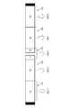
- FIG. 7 shows an example of how to allocate RUs when allocating a plurality of RUs to one STA.
- FIG. 7 shows a case where each STA has a frequency bandwidth of 20 MHz and is divided into four RUs having 52 subcarriers and one RU having 26 subcarriers, and a plurality of discontinuous RUs are assigned to each STA.
- the first RU701 and the fourth RU704 from the left are assigned to the STA (for example, the communication device 103) having an AID of 1.
- the second RU702 and the fifth RU705 from the left are assigned to an STA having an AID of 2, for example, a communication device 104.
- the third RU (RU with 26 subcarriers) 703 from the left is assigned to a STA having an AID of 3 (for example, a communication device 105).
- the communication device 102 which is an AP, transmits an EHT MU PPDU including a plurality of User fields having the same STA-ID to the EHT-SIG-B406.
- EHT MU PPDU with B406 is transmitted.
- the communication device 102 includes two or more User fields including the same STA-ID in the plurality of EHT MU PPDUs in the order corresponding to the assigned RUs, so that one STA has a frequency component. Can be assigned multiple RUs that are not contiguous.
- the communication device 102 includes a plurality of STAs having continuous frequency components.
- RU may be assigned.
- STAs can be assigned to RUs to which STAs have not been assigned by the conventional method, so that the utilization efficiency of the frequency band can be obtained. Is improved.
- the RU Allocation subfield 420 indicating how to divide the RU is included in the Common field 410, but the present invention is not limited to this.
- information indicating the RU assigned to each STA may be included in the User fields 411 to 419.
- one User field including information indicating a plurality of RUs may be included instead of including a plurality of User fields indicating the same STA.
- FIG. 5 shows an example of the frame format of the Trigger Frame transmitted by the communication device 102.
- Trigger Frame is a frame format used by a communication device conforming to the IEEE802.11be standard when executing UL MU communication.
- the communication device 102 indicates the STA that performs UL communication in the Trigger Frame and the RU assigned to each STA, and receives data in parallel from each STA via the designated RU.
- the Tiger Frame is composed of the Frame control 505, Duration 506, RA507, and TA508 fields from the beginning. Further, following TA508, it is composed of each field of Common Info501, User Info502, Padding 503, and FCS504.
- the Frame control 505 includes information indicating whether the frame is a management frame, a control frame, or a data frame, and information indicating a subtype of the frame.
- the frame subtype is information indicating whether the frame is a beacon or an action.
- Trigger Frame information indicating that the frame is a control frame and information indicating that the subtype is Trigger are entered.
- Duration 506 includes information for causing the STA that has received the Trigger Frame to set NAV (network allocation vector), which is a period during which communication is not started.
- NAV network allocation vector
- the RA (receiver addless) 507 includes a value determined based on the type of the trigger frame and the presence / absence of the User Info field.
- the TA (transmitter addless) 508 includes the address of the communication device that transmits the trigger frame.
- the TA508 includes an identifier (BSSID, Basic Service Set Idea) of the network to which the communication device that transmitted the trigger frame belongs.
- Trigger Type 510 indicates 0, and the communication time common to all STAs is set in Length 511.
- the User Info field (502-1 to 502-N) is added to the Tiger Frame.
- User Info502 includes AID520 for identifying STA.
- the RU Allocation 521 includes information indicating the size of the RU assigned to the STA indicated by the AID 520 and the number of the RU assigned to the STA counting from the RU having the lowest frequency.
- the Trigger Frame includes UL MCS522 including information for designating the modulation method and the coding rate of the data transmitted by the STA to the AP.
- Reserved 523 is an area reserved for the future.
- one User Frame When allocating one RU per STA shown in AID520 of User Info502, one User Frame includes one User Info field per STA.
- a plurality of RUs are assigned to one STA, a plurality of User Infos including the same AID are included in one Trigger Frame.
- the communication device 102 may generate a Trigger Frame indicating a plurality of RUs in one User Info RU Allocation.
- one RU Allocation field included in one User Info may include information about a plurality of RUs.
- one User Info may include a plurality of RU Allocation fields.
- Padding 503 is a field for adjusting the size of the Trigger Frame, and may be omitted.
- FCS504 is an abbreviation for Frame check sequence, and is an error detection code used to check whether an error has occurred in data during communication.
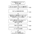
- FIG. 8 is a flowchart showing a process executed by the control unit 202 reading and executing the computer program stored in the storage unit 201 when the communication device 102 performs DL-OFDMA communication.
- the communication device 102 starts the processing of this flow when the user is instructed to perform DL-OFDMA communication to the STA.
- the processing of this flow may be started, or the buffer amount of data addressed to a predetermined number of STAs reaches a predetermined threshold value. It may be started when it exceeds.
- the processing of this flow may be started based on an instruction from the application operating on the communication device 102.
- the communication device 102 acquires the buffer amount of data stored in the own device to each STA (S800). In this step, it is only necessary to acquire the buffer amount of the data addressed to the STA, which is the other device for transmitting the EHT MU PPDU in S804 described later.
- the communication device 102 acquires the communication quality with each STA (S801).
- the communication device 102 may acquire the communication quality in the RU used in the previous communication with each STA, or may acquire the communication quality in the temporarily allocated RU.
- the communication quality acquired here is at least one of RSSI and SNR.
- RSSI is an abbreviation for Received Signal Strength Information (received signal strength).
- SNR is an abbreviation for Signal-to-Noise Ratio (signal-to-noise ratio).
- the communication device 102 may store at least one of RSSI or SNR at the time of the previous communication with each STA.
- the communication quality may be measured by instructing the STA by the communication device 102 (AP) to transmit a frame from the STA to the communication device 102.
- the communication device 102 transmits an NDP (null data PPDU) Announcement frame to the STA, thereby instructing the STA to transmit the NDP frame to the AP.
- NDP nucleic acid data PPDU
- the STA receives the NDP Announcement frame, it transmits the NDP frame to the AP.
- the AP measures the communication quality using the received NDP frame.
- the method of causing the STA to transmit an NDP frame in this way is called NDP Sounding.
- the communication quality may be acquired by transmitting a frame from the AP to the STA, causing the STA to measure the communication quality, and receiving the measurement result from the STA.
- the communication quality of the entire frequency channel used for communication with the STA may be acquired instead of the communication quality of the RU.
- the communication device 102 determines the RU to be assigned to each STA based on the buffer amount acquired in S800 and the communication quality acquired in S801 (S802). For example, the communication device 102 determines to allocate a plurality of RUs to STAs whose buffer amount acquired in S800 exceeds a predetermined threshold value. Further, when at least one of RSSI and SNR, which are the communication qualities acquired in S801, is equal to or less than a predetermined threshold value, it is determined to allocate a plurality of RUs. Further, when at least one of RSSI and SNR acquired in S801 for a certain STA is equal to or less than a predetermined threshold value, a RU different from the RU used in S801 may be assigned to the STA.
- the communication device 102 allocates two RUs having 26 subcarriers whose frequency components are discontinuous to the STA.
- the communication device 102 determines the allocation of the RU based on both the buffer amount and the communication quality, but the determination is not limited to this, and the determination may be made based on only one of them. In that case, since the communication device 102 does not need to acquire the information (buffer amount or communication quality) that is not used for determining the allocation of the RU, the corresponding S800 or S801 may be skipped.
- the communication device 102 determines the allocation of the RU to each STA, it generates an EHT MU PPDU including the User field corresponding to the allocation (S803). If it is determined in S802 that a plurality of RUs are assigned to one STA, the EHTMU PPDU generated in S803 includes a plurality of User fields including the same STA-ID.
- the present invention is not limited to this, and it is shown in other fields before the User field included in the EHT MU PPDU. You may. If it is shown that a plurality of RUs are not assigned to one STA, the STA does not need to analyze the User field after detecting the corresponding User field. Thereby, the processing load of STA can be reduced.
- the communication device 102 transmits the EHT MU PPDU generated in S803 to the STA (S804).
- the EHT MU PPDU transmitted in this step includes data addressed to the same STA in the plurality of RUs.
- signals corresponding to each field are transmitted in the order of L-LTF402, L-SIG403, RL-SIG404, EHT-SIG-A405, and EHT-SIG-B406 in order from L-STF401 shown in FIG. ..
- the communication device 102 may start the transmission of S804 after generating all the above fields in S803, or may generate the S803 and transmit the S804 in parallel. Specifically, the communication device 102 generates the L-STF401, and in parallel with transmitting the signal corresponding to the generated L-STF401, generates the L-LTF402 which is the field to be transmitted next. You may do so.
- the STA that receives the EHT MU PPDU transmitted in S804 corresponds to each field in the order of L-STF401, L-LTF402, L-SIG403, RL-SIG404, EHT-SIG-A405, and EHT-SIG-B406. Receive the signal. Further, the STA receives signals corresponding to each field in the order of EHT-STF407, EHT-LTF408, and PSDU409 following EHT-SIG-B406.
- the communication device 102 can transmit the EHT MU PPDU including the information indicating that a plurality of RUs are assigned to the same STA. As a result, the communication device 102 can improve the utilization efficiency of the frequency band. Further, the communication device 102 allocates a plurality of RUs to the same STA or one RU to one STA in consideration of the amount of data buffered in the STA and the communication quality with each STA. be able to. The communication device 102 can flexibly allocate the RU based on the amount of data buffer for each STA and the communication quality with each STA.
- FIG. 9 is a flowchart showing a process executed by the control unit 202 reading and executing the computer program stored in the storage unit 201 when the communication device 102 performs UL-OFDMA communication.
- the communication device 102 starts the processing of this flow when the user is instructed to perform UL-OFDMA communication to the STA.
- the processing of this flow may be started based on the request from the STA to perform UL-OFDA communication.
- the processing of this flow may be started based on an instruction from the application operating on the communication device 102.
- the communication device 102 acquires the buffer amount of the transmission data held by each STA belonging to the network 101 (S900). In this step, only the buffer amount of a part of the STAs belonging to the network 101 may be acquired.
- the communication device 102 receives notification of the buffer amount from the STA by the Buffer Status Report (BSR) frame defined in the IEEE802.11ax standard. Specifically, first, the communication device 102 transmits a BSR Poll requesting each STA to be notified of the amount of data held by each STA. As a response to the request frame, each STA transmits a Buffer status report frame notifying the amount of data to the communication device 102 held by the own device to the communication device 102. The communication device 102 can acquire the data amount of the data addressed to the communication device 102 held by each STA from the received BSR frame.
- BSR Buffer Status Report
- the communication device 102 acquires the communication quality with each STA (S901).
- the processing of this step is the same as that of S801.
- the communication device 102 determines the RU to be assigned to each STA based on the buffer amount acquired in S900 and the communication quality acquired in S901 (S902). The processing of this step is the same as that of S802.
- the communication device 102 determines the allocation of the RU to each STA, the communication device 102 generates a Trigger Frame including the User info field corresponding to the allocation (S903). If it is determined in S902 that a plurality of RUs are assigned to one STA, the Tiger Frame generated in S903 includes a plurality of User Info fields containing the same AID. Alternatively, a Trigger Frame having a User Info field including a RU allocation subfield indicating a plurality of RUs may be generated.
- the User Info fields containing the same AID may be continuously arranged in the Trigger Frame.
- the STA that receives the Trigger Frame analyzes the User Info field addressed to its own device and then detects the User Info field addressed to the STA different from its own device, it is not necessary to analyze the subsequent User Info field. .. Thereby, the processing load of STA can be reduced.
- whether or not a plurality of RUs are assigned to one STA may be indicated by other fields included in the Trigger Frame. For example, the information may be shown in the Reserved 512 shown in FIG. When it is shown in Reserved 512 that a plurality of RUs are not assigned to the same STA, the STA does not need to analyze the User Info field after the User Info field addressed to the own device.
- the communication device 102 transmits the Trigger Frame generated in S904 to the STA (S904).
- signals corresponding to each field are transmitted in the order of Duration 506, RA507, and TA508 in order from Frame control 505 shown in FIG.
- signals corresponding to the fields of Common Info501, User Info502, Padding 503, and FCS504 are transmitted in order.
- the communication device 102 may start the transmission of S904 after all the above fields are generated in S903, or the generation of S903 and the transmission of S904 may be performed in parallel.
- the communication device 102 may generate the Frame control 505 and, in parallel with transmitting the signal corresponding to the generated Frame control 505, generate the Duration 506 which is the field to be transmitted next. Good.
- the STA that receives the Trigger Frame transmitted in S904 receives the signals corresponding to each field in the order of Duration 506, RA507, and TA508 in order from Frame control 505. Further, the STA receives the signals corresponding to each field in the order of COMMON Info501, UserInfo502, Padding503, and FCS504, following TA508.
- the communication device 102 receives data from the STA using the RU specified in the Trigger Frame transmitted in S904. Specifically, the communication device 102 receives data from each STA by the EHT TB (Trigger Based) PPDU.
- EHT TB Trigger Based
- the communication device 102 can transmit a Trigger Frame including information indicating that a plurality of RUs are assigned to the same STA. As a result, the communication device 102 can improve the utilization efficiency of the frequency band. Further, the communication device 102 allocates a plurality of RUs to the same STA or allocates one RU to one STA in consideration of the amount of data buffered to the AP in the STA and the communication quality with each STA. Can be done. The communication device 102 can flexibly allocate the RU based on the amount of data buffered to the AP in each STA and the communication quality with each STA.
- the wireless communication conforming to the IEEE802.11be standard has been described as an example, but the present invention is not limited to this, and the same processing may be performed in the wireless communication conforming to the IEEE802.11ax standard which is a legacy standard. ..
- the EHT field is replaced with the HE field, for example, the name of the EHT-SIG-B field becomes the HE-SIG-B field.
- it may be realized by wireless communication conforming to a standard that is a successor to the IEEE802.11be standard. Again, the EHT field is replaced with the corresponding field that complies with the applicable standard.
- FIGS. 8 and 9 may be realized by hardware.
- a dedicated circuit may be generated on the FPGA from a computer program for realizing each step, and this may be used.
- FPGA is an abbreviation for Field Programmable Gate Array.
- a Gate Array circuit may be formed in the same manner as the FPGA and realized as hardware. Further, it may be realized by ASIC (Application Specific Integrated Circuit).
- the present invention supplies a program that realizes one or more functions of the above-described embodiment to a system or device via a network or storage medium, and one or more processors in the computer of the system or device reads and executes the program. It can also be realized by the processing to be performed. It can also be realized by a circuit (for example, ASIC) that realizes one or more functions.
Landscapes
- Engineering & Computer Science (AREA)
- Signal Processing (AREA)
- Computer Networks & Wireless Communication (AREA)
- Quality & Reliability (AREA)
- Mobile Radio Communication Systems (AREA)
- Communication Control (AREA)
Abstract
Description

Claims (22)
- 通信装置であって、
L-STF(Legacy-Short Training Field)と、
前記L-STFの後のL-LTF(Legacy-Long Training Field)と、
前記L-LTFの後のL-SIG(Legacy-Signal)と、
前記L-SIGの後のEHT-SIG-A(Extremely High Throughput-Signal-A)と、
前記EHT-SIG-Aの後のフィールドであって、1つの他の通信装置に複数のRU(Resource Unit)が割り当てられていることを示す情報を含むEHT-SIG-Bと、
前記EHT-SIG-Bの後のEHT-STF(Extremely High Throughput-Short Training Field)と、
前記EHT-STFの後のEHT-LTF(Extremely High Throughput-Long Training Field)と、を含むEHT MU(Multi User) PPDU(Physical Layer Protocol Data Unit)を生成する生成手段と、
前記生成手段によって生成された前記EHT MU PPDUを送信する送信手段と、を有することを特徴とする通信装置。 - 前記生成手段によって生成される前記EHT MU PPDUは、前記他の通信装置に対応するSTA-ID(Station Identification)を有する複数のUserフィールドを含む前記EHT-SIG-Bを含むことを特徴とする請求項1に記載の通信装置。
- 前記Userフィールドには、前記STA-IDに対応する前記他の通信装置を宛先とするデータに使用された符号化率と変調方式とを示す情報を含むMCS(Modulation and Coding Scheme)フィールドが更に含まれることを特徴とする請求項2に記載の通信装置。
- 前記EHT-SIG-Bには、更にCommonフィールドが含まれ、前記CommonフィールドにはRUの割り当てを示すRU allocationが含まれることを特徴とする請求項1から3のいずれか1項に記載の通信装置。
- 前記RU allocationにおいて示されたRUの内、周波数が低いRUから順に、先頭のUserフィールドに含まれるSTA-IDに対応する他の通信装置に割り当てられることを特徴とする請求項4に記載の通信装置。
- 前記他の通信装置を宛先とするデータのバッファ量を取得する第1の取得手段と、
前記他の通信装置との通信品質を取得する第2の取得手段と、
前記第1の取得手段によって取得した前記バッファ量と、前記第2の取得手段によって取得した前記通信品質との少なくとも一方に基づいて、前記他の通信装置に対するRUの割り当てを決定する決定手段を更に有し、
前記生成手段は前記決定手段によって決定されたRUの割り当てに基づいて、前記EHT MU PPDUを生成することを特徴とする請求項1から5のいずれか1項に記載の通信装置。 - 前記第2の取得手段によって取得される前記通信品質は、RSSI(ReceivedSignal Strength Indication)またはSNR(Signal-to-Noise Ratio)の少なくとも一方であることを特徴とする請求項6に記載の通信装置。
- 前記複数のRUは周波数成分が不連続であることを特徴とする請求項1から7のいずれか1項に記載の通信装置。
- 前記生成手段は、IEEE802.11be規格に準拠した前記EHT MU PPDUを生成することを特徴とする請求項1から8のいずれか1項に記載の通信装置。
- 通信装置であって、
Frame controlと、
前記Frame controlの後のDurationと、
前記Durationの後のRA(receiver address)と、
前記RAの後のTA(transmitter address)と、
前記TAの後のCommon Infoと、
前記Common Infoの後であって、1つの他の通信装置に複数のRU(Resource Unit)が割り当てられていることを示す情報を含むUser Infoと、を含むTrigger Frameを生成する生成手段と、
前記生成手段によって生成された前記Trigger Frameを送信する送信手段と、
を有することを特徴とする通信装置。 - 前記生成手段によって生成される前記Trigger Frameには、前記他の通信装置に対応するAIDを含む前記User Infoが複数含まれることを特徴とする請求項10に記載の通信装置。
- 前記生成手段は、前記他の通信装置に対応する前記AIDを含む複数の前記User Infoフィールドが連続するように前記Trigger Frameを生成することを特徴とする請求項11に記載の通信装置。
- 前記生成手段によって生成される前記Trigger Frameには、前記他の通信装置に対応するAIDを含み、かつ複数のRUを示す情報を含む前記User Infoが含まれることを特徴とする請求項10に記載の通信装置。
- 前記送信手段によって送信した前記Trigger Frameを受信した前記複数の他の通信装置に含まれる他の通信装置から、前記Trigger Frameにおいて示したRUを介してデータを受信する受信手段を更に有することを特徴とする請求項10から13のいずれか1項に記載の通信装置。
- 前記User Infoフィールドには、前記他の通信装置が前記通信装置にデータを送信する際に利用する変調方式と符号化率とを指定するための情報を含むUL MCS(Up Link Modulation and Coding Scheme)が更に含まれることを特徴とする請求項11から14のいずれか1項に記載の通信装置。
- 前記他の通信装置から前記通信装置を宛先とするデータのバッファ量を取得する第1の取得手段と、
前記他の通信装置との通信品質を取得する第2の取得手段と、
前記第1の取得手段によって取得した前記バッファ量と、前記第2の取得手段によって取得した前記通信品質との少なくとも一方に基づいて、前記他の通信装置に対するRUの割り当てを決定する決定手段を更に有し、
前記生成手段は前記決定手段によって決定されたRUの割り当てに基づいて、前記Trigger Frameを生成することを特徴とする請求項10から15のいずれか1項に記載の通信装置。 - 前記第2の取得手段によって取得される前記通信品質は、RSSI(ReceivedSignal Strength Indication)またはSNR(Signal-to-Noise Ratio)の少なくとも一方であることを特徴とする請求項16に記載の通信装置。
- 前記複数のRUは周波数成分が不連続であることを特徴とする請求項10から17のいずれか1項に記載の通信装置。
- 前記生成手段は、IEEE802.11be規格に準拠した前記Trigger Frameを生成することを特徴とする請求項10から18のいずれか1項に記載の通信装置。
- 通信装置の制御方法であって、
L-STF(Legacy-Short Training Field)と、
前記L-STFの後のL-LTF(Legacy-Long Training Field)と、
前記L-LTFの後のL-SIG(Legacy-Signal)と、
前記L-SIGの後のEHT-SIG-A(Extremely High Throughput-Signal-A)と、
前記EHT-SIG-Aの後のフィールドであって、1つの他の通信装置に複数のRU(Resource Unit)が割り当てられていることを示す情報を含むEHT-SIG-Bと、
前記EHT-SIG-Bの後のEHT-STF(Extremely High Throughput-Short Training Field)と、
前記EHT-STFの後のEHT-LTF(Extremely High Throughput-Long Training Field)と、を含むEHT MU(Multi User) PPDU(Physical Layer Protocol Data Unit)を生成する生成工程と、
前記生成工程において生成された前記EHT MU PPDUを送信する送信工程と、を有することを特徴とする制御方法。 - 通信装置の制御方法であって、
Frame controlと、
前記Frame controlの後のDurationと、
前記Durationの後のRA(receiver address)と、
前記RAの後のTA(transmitter address)と、
前記TAの後のCommon Infoと、
前記Common Infoの後であって、1つの他の通信装置に複数のRU(Resource Unit)が割り当てられていることを示す情報を含むUser Infoと、を含むTrigger Frameを生成する生成工程と、
前記生成工程において生成された前記Trigger Frameを送信する送信工程と、
を有することを特徴とする制御方法。 - コンピュータを請求項1から19のいずれか1項に記載の通信装置の各手段として機能させるためのプログラム。
Priority Applications (8)
| Application Number | Priority Date | Filing Date | Title |
|---|---|---|---|
| EP20886043.7A EP4057743A4 (en) | 2019-11-07 | 2020-10-27 | COMMUNICATION DEVICE, CONTROL METHOD AND PROGRAM |
| CN202080074217.0A CN114631343B (zh) | 2019-11-07 | 2020-10-27 | 通信装置、控制方法和程序 |
| KR1020257035141A KR20250159061A (ko) | 2019-11-07 | 2020-10-27 | 통신 장치, 제어 방법 및 프로그램 |
| KR1020227017804A KR102876096B1 (ko) | 2019-11-07 | 2020-10-27 | 통신 장치, 제어 방법 및 프로그램 |
| BR112022007557A BR112022007557A2 (pt) | 2019-11-07 | 2020-10-27 | Aparelho de comunicação, método de controle e programa |
| CN202610206372.2A CN122093810A (zh) | 2019-11-07 | 2020-10-27 | 通信装置、控制方法和程序 |
| US17/735,468 US12317299B2 (en) | 2019-11-07 | 2022-05-03 | Communication apparatus, control method, and storage medium |
| US19/195,528 US20250261221A1 (en) | 2019-11-07 | 2025-04-30 | Communication apparatus, control method, and storage medium |
Applications Claiming Priority (2)
| Application Number | Priority Date | Filing Date | Title |
|---|---|---|---|
| JP2019202783A JP7527772B2 (ja) | 2019-11-07 | 2019-11-07 | 通信装置、制御方法、およびプログラム |
| JP2019-202783 | 2019-11-07 |
Related Child Applications (1)
| Application Number | Title | Priority Date | Filing Date |
|---|---|---|---|
| US17/735,468 Continuation US12317299B2 (en) | 2019-11-07 | 2022-05-03 | Communication apparatus, control method, and storage medium |
Publications (1)
| Publication Number | Publication Date |
|---|---|
| WO2021090732A1 true WO2021090732A1 (ja) | 2021-05-14 |
Family
ID=75848349
Family Applications (1)
| Application Number | Title | Priority Date | Filing Date |
|---|---|---|---|
| PCT/JP2020/040257 Ceased WO2021090732A1 (ja) | 2019-11-07 | 2020-10-27 | 通信装置、制御方法、およびプログラム |
Country Status (7)
| Country | Link |
|---|---|
| US (2) | US12317299B2 (ja) |
| EP (1) | EP4057743A4 (ja) |
| JP (2) | JP7527772B2 (ja) |
| KR (2) | KR20250159061A (ja) |
| CN (2) | CN114631343B (ja) |
| BR (1) | BR112022007557A2 (ja) |
| WO (1) | WO2021090732A1 (ja) |
Families Citing this family (6)
| Publication number | Priority date | Publication date | Assignee | Title |
|---|---|---|---|---|
| CN122204263A (zh) * | 2020-01-10 | 2026-06-12 | 华为技术有限公司 | 无线局域网前导码中的资源分配信令 |
| CN121193394A (zh) * | 2020-01-11 | 2025-12-23 | 华为技术有限公司 | 打孔信息的指示方法及通信装置 |
| JP7494789B2 (ja) | 2021-04-30 | 2024-06-04 | 株式会社デンソー | 減速機付モータ |
| CN115442894A (zh) * | 2021-06-03 | 2022-12-06 | 华为技术有限公司 | 一种物理层协议数据单元、触发帧的传输方法以及装置 |
| WO2023204600A1 (ko) * | 2022-04-20 | 2023-10-26 | 엘지전자 주식회사 | 무선랜 시스템에서 새로운 뉴머롤로지에 대한 stf 송신 또는 수신 방법 및 장치 |
| JP2025021773A (ja) * | 2023-08-01 | 2025-02-14 | キヤノン株式会社 | 通信装置、制御方法、及び、プログラム |
Citations (4)
| Publication number | Priority date | Publication date | Assignee | Title |
|---|---|---|---|---|
| US20170086212A1 (en) | 2014-06-08 | 2017-03-23 | Lg Electronics Inc. | Uplink multi-user transmission method in wireless lan system and apparatus therefor |
| JP2018526840A (ja) * | 2015-07-01 | 2018-09-13 | パナソニックIpマネジメント株式会社 | 送信装置、送信方法および集積回路 |
| US20190327019A1 (en) * | 2018-04-23 | 2019-10-24 | Avago Technologies General Ip (Singapore) Pte. Ltd. | Range extension of wireless communication device |
| JP2019202783A (ja) | 2018-05-21 | 2019-11-28 | 京セラドキュメントソリューションズ株式会社 | 緩衝材 |
Family Cites Families (19)
| Publication number | Priority date | Publication date | Assignee | Title |
|---|---|---|---|---|
| WO2016167609A1 (ko) * | 2015-04-16 | 2016-10-20 | 엘지전자(주) | 무선 통신 시스템에서 채널 사운딩 방법 및 이를 위한 장치 |
| US10505691B2 (en) * | 2015-08-20 | 2019-12-10 | Lg Electronics Inc. | Method and apparatus for configuring frame unit comprising control field indicating data fields in wireless LAN system |
| JP6402121B2 (ja) * | 2016-01-06 | 2018-10-10 | 株式会社東芝 | 無線通信装置および無線通信方法 |
| EP3488659B8 (en) * | 2016-07-22 | 2023-03-08 | Panasonic Intellectual Property Corporation of America | Transmission appratus and transmission method |
| WO2018128042A1 (ja) * | 2017-01-06 | 2018-07-12 | パナソニック インテレクチュアル プロパティ コーポレーション オブ アメリカ | 通信装置、端末および通信方法 |
| TWI848849B (zh) * | 2017-02-21 | 2024-07-11 | 美商松下電器(美國)知識產權公司 | 通訊裝置及積體電路 |
| US11044056B2 (en) * | 2018-02-01 | 2021-06-22 | Mediatek Singapore Pte. Ltd. | Enhanced resource unit allocation schemes for OFDMA transmission in WLAN |
| US11457439B2 (en) * | 2018-04-20 | 2022-09-27 | Lg Electronics Inc. | Method and device for executing communication via uplink access in wireless LAN system |
| CN116867076A (zh) * | 2018-08-23 | 2023-10-10 | Lg电子株式会社 | 无线局域网系统中的站和接入点及其执行的方法 |
| JP7308623B2 (ja) * | 2019-02-28 | 2023-07-14 | キヤノン株式会社 | 情報処理装置並びにその制御方法、及び、プログラム |
| CN111698067B (zh) * | 2019-03-15 | 2023-03-10 | 华为技术有限公司 | 数据传输方法及装置 |
| CN111726203B (zh) * | 2019-03-19 | 2021-12-21 | 华为技术有限公司 | 回复确认帧的方法及装置、数据传输系统 |
| US11728942B2 (en) * | 2019-03-22 | 2023-08-15 | Qualcomm Incorporated | Data parsing to support resource unit aggregation |
| JP7398874B2 (ja) * | 2019-04-11 | 2023-12-15 | キヤノン株式会社 | 通信装置並びにその通信方法、情報処理装置並びにその制御方法、及び、プログラム |
| US11128515B2 (en) * | 2019-04-30 | 2021-09-21 | Intel Corporation | Extreme high throughput future proof preamble design |
| US11212705B2 (en) * | 2019-05-28 | 2021-12-28 | Nxp Usa, Inc. | Extra high throughput preamble |
| US11665574B2 (en) * | 2019-10-25 | 2023-05-30 | Qualcomm Incorporated | Physical layer preamble design for special packet types |
| JP7379100B2 (ja) * | 2019-11-08 | 2023-11-14 | キヤノン株式会社 | 通信装置、通信方法、およびプログラム |
| CN113133115B (zh) * | 2020-01-10 | 2025-03-11 | 华为技术有限公司 | 指示多资源单元Multi-RU合并的方法和装置 |
-
2019
- 2019-11-07 JP JP2019202783A patent/JP7527772B2/ja active Active
-
2020
- 2020-10-27 KR KR1020257035141A patent/KR20250159061A/ko active Pending
- 2020-10-27 CN CN202080074217.0A patent/CN114631343B/zh active Active
- 2020-10-27 KR KR1020227017804A patent/KR102876096B1/ko active Active
- 2020-10-27 WO PCT/JP2020/040257 patent/WO2021090732A1/ja not_active Ceased
- 2020-10-27 BR BR112022007557A patent/BR112022007557A2/pt unknown
- 2020-10-27 EP EP20886043.7A patent/EP4057743A4/en active Pending
- 2020-10-27 CN CN202610206372.2A patent/CN122093810A/zh active Pending
-
2022
- 2022-05-03 US US17/735,468 patent/US12317299B2/en active Active
-
2024
- 2024-07-25 JP JP2024119346A patent/JP2024150683A/ja active Pending
-
2025
- 2025-04-30 US US19/195,528 patent/US20250261221A1/en active Pending
Patent Citations (4)
| Publication number | Priority date | Publication date | Assignee | Title |
|---|---|---|---|---|
| US20170086212A1 (en) | 2014-06-08 | 2017-03-23 | Lg Electronics Inc. | Uplink multi-user transmission method in wireless lan system and apparatus therefor |
| JP2018526840A (ja) * | 2015-07-01 | 2018-09-13 | パナソニックIpマネジメント株式会社 | 送信装置、送信方法および集積回路 |
| US20190327019A1 (en) * | 2018-04-23 | 2019-10-24 | Avago Technologies General Ip (Singapore) Pte. Ltd. | Range extension of wireless communication device |
| JP2019202783A (ja) | 2018-05-21 | 2019-11-28 | 京セラドキュメントソリューションズ株式会社 | 緩衝材 |
Non-Patent Citations (4)
| Title |
|---|
| ROYA, DOOSTNEJAD (INTEL CORPORATION ET AL.: "Implicit Channel Sounding in IEEE 802.11", IEEE 802.11-19/0768RL, 24 June 2019 (2019-06-24), XP068151057, Retrieved from the Internet <URL:https://mentor.ieee.org/802.11/dcn/19/11-19-0768-01-00be-implicit-channel-sounding-in-ieee-802-11.pptx> [retrieved on 20210105] * |
| RUI, CAO (MARVELL ET AL.: "EHT Preamble Design", IEEE 802.11-19/1540RO, 15 September 2019 (2019-09-15), pages 1 - 14, XP068153683, Retrieved from the Internet <URL:https://mentor.ieee.org/802.11/dcn/19/11-19-1540-00-00be-eht-preamble-design.pptx> [retrieved on 20210105] * |
| SAMEER, VERMANI (QUALCOMM ET AL.: "Further Ideas on EHT Preamble Design", IEEE 802.11-19/1870R4, 14 November 2019 (2019-11-14), XP068164733, Retrieved from the Internet <URL:https://mentor.ieee.org/802.11/dcn/19/11-19-1870-04-00be-further-ideas-on-eht-preamble-design.pptx> [retrieved on 20210105] * |
| See also references of EP4057743A4 |
Also Published As
| Publication number | Publication date |
|---|---|
| CN114631343B (zh) | 2026-03-13 |
| US20250261221A1 (en) | 2025-08-14 |
| US12317299B2 (en) | 2025-05-27 |
| JP7527772B2 (ja) | 2024-08-05 |
| KR102876096B1 (ko) | 2025-10-24 |
| EP4057743A1 (en) | 2022-09-14 |
| JP2024150683A (ja) | 2024-10-23 |
| BR112022007557A2 (pt) | 2022-07-05 |
| CN114631343A (zh) | 2022-06-14 |
| CN122093810A (zh) | 2026-05-26 |
| US20220264579A1 (en) | 2022-08-18 |
| JP2021077981A (ja) | 2021-05-20 |
| KR20250159061A (ko) | 2025-11-07 |
| KR20220092545A (ko) | 2022-07-01 |
| EP4057743A4 (en) | 2023-12-06 |
Similar Documents
| Publication | Publication Date | Title |
|---|---|---|
| US11082181B2 (en) | System and method for orthogonal frequency division multiple access communications | |
| JP7527772B2 (ja) | 通信装置、制御方法、およびプログラム | |
| JP2023053379A (ja) | 通信装置、制御方法、及びプログラム | |
| JP7361880B2 (ja) | マルチユーザ送信における送信パラメータ値を選択するための方法および装置 | |
| JP7379100B2 (ja) | 通信装置、通信方法、およびプログラム | |
| JP7600303B2 (ja) | 通信装置及びその通信方法、情報処理装置及びその制御方法、及び、プログラム | |
| US12615677B2 (en) | Communication apparatus, communication control method, communication method, and computer-readable storage medium | |
| JP7433770B2 (ja) | 通信装置、情報処理装置、制御方法、及び、プログラム | |
| CN115669194A (zh) | 通信设备、通信方法和程序 | |
| JP2024156929A (ja) | 通信装置、情報処理装置、制御方法、およびプログラム | |
| US20230232483A1 (en) | Communication apparatus, control method, and storage medium | |
| CN114128158A (zh) | 基站、发送方法及接收方法 | |
| WO2024004588A1 (ja) | 通信装置、制御方法、およびプログラム | |
| US11483730B2 (en) | Communication apparatus, communication MElHOD, and storage medium | |
| JP2020141326A (ja) | 通信装置、情報処理装置、制御方法、およびプログラム | |
| JP2025171096A (ja) | 通信装置、通信方法及びプログラム | |
| KR20260056255A (ko) | 액세스 포인트 장치, 제어 방법, 및 프로그램 | |
| CN122070669A (zh) | 非对称协调波束成形协议 | |
| BR122023022265A2 (pt) | Aparelho de comunicação, método de controle e programa |
Legal Events
| Date | Code | Title | Description |
|---|---|---|---|
| 121 | Ep: the epo has been informed by wipo that ep was designated in this application |
Ref document number: 20886043 Country of ref document: EP Kind code of ref document: A1 |
|
| REG | Reference to national code |
Ref country code: BR Ref legal event code: B01A Ref document number: 112022007557 Country of ref document: BR |
|
| ENP | Entry into the national phase |
Ref document number: 20227017804 Country of ref document: KR Kind code of ref document: A |
|
| NENP | Non-entry into the national phase |
Ref country code: DE |
|
| ENP | Entry into the national phase |
Ref document number: 2020886043 Country of ref document: EP Effective date: 20220607 |
|
| ENP | Entry into the national phase |
Ref document number: 112022007557 Country of ref document: BR Kind code of ref document: A2 Effective date: 20220420 |
|
| WWD | Wipo information: divisional of initial pct application |
Ref document number: 202648001367 Country of ref document: IN |
|
| WWP | Wipo information: published in national office |
Ref document number: 202648001367 Country of ref document: IN |
|
| WWG | Wipo information: grant in national office |
Ref document number: 202247031364 Country of ref document: IN |