WO2021090795A1 - ポンプケーシングおよびポンプ装置 - Google Patents
ポンプケーシングおよびポンプ装置 Download PDFInfo
- Publication number
- WO2021090795A1 WO2021090795A1 PCT/JP2020/041018 JP2020041018W WO2021090795A1 WO 2021090795 A1 WO2021090795 A1 WO 2021090795A1 JP 2020041018 W JP2020041018 W JP 2020041018W WO 2021090795 A1 WO2021090795 A1 WO 2021090795A1
- Authority
- WO
- WIPO (PCT)
- Prior art keywords
- suction
- pump casing
- rib
- hydro
- outer edge
- Prior art date
- Legal status (The legal status is an assumption and is not a legal conclusion. Google has not performed a legal analysis and makes no representation as to the accuracy of the status listed.)
- Ceased
Links
Images


Classifications
-
- F—MECHANICAL ENGINEERING; LIGHTING; HEATING; WEAPONS; BLASTING
- F04—POSITIVE - DISPLACEMENT MACHINES FOR LIQUIDS; PUMPS FOR LIQUIDS OR ELASTIC FLUIDS
- F04D—NON-POSITIVE-DISPLACEMENT PUMPS
- F04D29/00—Details, component parts, or accessories
- F04D29/40—Casings; Connections of working fluid
- F04D29/42—Casings; Connections of working fluid for radial or helico-centrifugal pumps
- F04D29/426—Casings; Connections of working fluid for radial or helico-centrifugal pumps especially adapted for liquid pumps
-
- F—MECHANICAL ENGINEERING; LIGHTING; HEATING; WEAPONS; BLASTING
- F04—POSITIVE - DISPLACEMENT MACHINES FOR LIQUIDS; PUMPS FOR LIQUIDS OR ELASTIC FLUIDS
- F04D—NON-POSITIVE-DISPLACEMENT PUMPS
- F04D13/00—Pumping installations or systems
- F04D13/02—Units comprising pumps and their driving means
- F04D13/06—Units comprising pumps and their driving means the pump being electrically driven
-
- F—MECHANICAL ENGINEERING; LIGHTING; HEATING; WEAPONS; BLASTING
- F04—POSITIVE - DISPLACEMENT MACHINES FOR LIQUIDS; PUMPS FOR LIQUIDS OR ELASTIC FLUIDS
- F04D—NON-POSITIVE-DISPLACEMENT PUMPS
- F04D29/00—Details, component parts, or accessories
- F04D29/40—Casings; Connections of working fluid
- F04D29/42—Casings; Connections of working fluid for radial or helico-centrifugal pumps
- F04D29/426—Casings; Connections of working fluid for radial or helico-centrifugal pumps especially adapted for liquid pumps
- F04D29/4293—Details of fluid inlet or outlet
-
- F—MECHANICAL ENGINEERING; LIGHTING; HEATING; WEAPONS; BLASTING
- F05—INDEXING SCHEMES RELATING TO ENGINES OR PUMPS IN VARIOUS SUBCLASSES OF CLASSES F01-F04
- F05D—INDEXING SCHEME FOR ASPECTS RELATING TO NON-POSITIVE-DISPLACEMENT MACHINES OR ENGINES, GAS-TURBINES OR JET-PROPULSION PLANTS
- F05D2240/00—Components
- F05D2240/10—Stators
- F05D2240/12—Fluid guiding means, e.g. vanes
- F05D2240/126—Baffles or ribs
-
- F—MECHANICAL ENGINEERING; LIGHTING; HEATING; WEAPONS; BLASTING
- F05—INDEXING SCHEMES RELATING TO ENGINES OR PUMPS IN VARIOUS SUBCLASSES OF CLASSES F01-F04
- F05D—INDEXING SCHEME FOR ASPECTS RELATING TO NON-POSITIVE-DISPLACEMENT MACHINES OR ENGINES, GAS-TURBINES OR JET-PROPULSION PLANTS
- F05D2260/00—Function
- F05D2260/94—Functionality given by mechanical stress related aspects such as low cycle fatigue [LCF] of high cycle fatigue [HCF]
- F05D2260/941—Functionality given by mechanical stress related aspects such as low cycle fatigue [LCF] of high cycle fatigue [HCF] particularly aimed at mechanical or thermal stress reduction
Definitions
- the present invention relates to a pump casing, particularly to a reinforcing structure of a pump casing accommodating an impeller.
- the present invention also relates to a pump device including such a pump casing.
- the centrifugal pump boosts the liquid in the pump casing by rotating the impeller in the pump casing, and discharges the boosted liquid to the outside from the discharge port.
- a high stress is generated in a part of the pump casing, and the pump casing is deformed.
- the pump casing is required to have strength to keep the deformation of the pump casing below a certain level.
- the pump casing Since the shape of the pump casing with the spiral chamber is complicated, the pump casing is generally manufactured by casting. If the wall thickness of the entire pump casing is increased in order to increase the strength of the pump casing, the weight of the pump casing increases, and as a result, the weight of the entire centrifugal pump increases.
- This water pressure resistance test is performed for the purpose of inspecting water leakage from the centrifugal pump. Specifically, with the impeller and rotating shaft removed from the pump casing, all openings including the suction port and discharge port of the pump casing are closed to form a closed space inside the pump casing, and this closed space is formed. Is filled with water having a pressure 1.5 times the maximum discharge pressure of the pump, and left as it is for 3 minutes or more to inspect for water leakage and deformation of the pump casing.
- an inching test is a test in which water leakage from the pump casing is inspected by repeatedly increasing the pressure in the pump casing from a state without pressure to a certain value.
- the pump casing is required to have high strength from the viewpoint of ensuring safe operation.
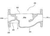
- FIG. 8 is a cross-sectional view showing an example of a conventional pump casing.
- the pump casing 200 has a suction hydro section 201 having a suction port 201a, and a volute hydro section 202 having a volute chamber 202a in which the impeller is housed and a discharge port 202b.
- the rib 205 extends from the suction hydro portion 201 to the discharge flange 206. Such a rib 205 can increase the moment of inertia of area of the pump casing 200 and improve the strength of the pump casing 200.
- This connecting portion X is a portion where the rib 205 and the suction hydro portion 201 are connected.
- This connecting portion X is a portion where the rib 205 and the suction hydro portion 201 are connected.
- a crack is generated on the outer surface of the connecting portion X.
- the crack grows toward the inside of the suction hydro portion 201 and eventually reaches the inner surface of the suction hydro portion 201.
- the cracks that reach the inside of the pump casing 200 cause liquid leakage from the pump casing 200. In particular, in an environment where the pump starts and stops frequently, cracks grow rapidly and the life of the pump casing 200 is shortened.
- the present invention provides a pump casing that can prevent liquid leakage by making it difficult for the cracks to reach the inside of the pump casing even if the ribs are cracked.
- the present invention also provides a pump device with such a pump casing.
- a volute chamber for accommodating an impeller, a volute hydro section having a discharge port, a suction hydro section having a suction port communicating with the volute chamber, and the volute hydro section and the suction hydro section.
- Each has a rib connected to an outer surface, the rib has a curved outer edge curved toward the inside of the rib, and the curved outer edge is smoothly connected to the outermost peripheral surface of the suction hydro portion.
- a pump casing in which the ratio of the radius of curvature of the curved outer edge to the radius of curvature of the outermost peripheral surface of the suction hydro portion is 20% or more.
- the tangent line on the curved outer edge and the tangent line on the outermost peripheral surface of the suction hydro portion coincide with each other.
- the rib is connected to a discharge flange that surrounds the discharge port.
- the curved outer edge of the rib extends from the suction hydro section to the discharge flange.
- a pump device including an impeller, an electric motor connected to the impeller, and the pump casing accommodating the impeller is provided.
- the stress is concentrated at a position away from the connection portion between the rib and the suction hydro portion.
- the rib having the curved outer edge of the radius of curvature can suck the stress-concentrated portion away from the hydro portion. Therefore, even if a crack is generated at the curved outer edge of the rib due to stress concentration, the crack extends to the inside of the rib and it is difficult to reach the suction hydro portion. That is, the cracks are less likely to reach the suction hydro portion by the height of the rib. As a result, it is possible to prevent the suction hydro portion itself from being cracked.
- FIG. 1 It is sectional drawing which shows one Embodiment of a pump device. It is a perspective view which shows one Embodiment of a pump casing. It is a bottom view of the pump casing shown in FIG. It is a side view of the pump casing shown in FIG. It is a side view of another embodiment of a pump casing. It is a side view of still another embodiment of a pump casing. It is a side view of still another embodiment of a pump casing. It is sectional drawing which shows an example of the conventional pump casing.
- FIG. 1 is a cross-sectional view showing an embodiment of a pump device.
- the pump device of the present embodiment is an in-line pump device in which a suction port and a discharge port are aligned in a straight line.
- This type of pumping device has no legs and the entire pumping device is supported by piping connected to the suction and discharge flanges.
- the pump device includes an electric motor 1, a rotating shaft 2 connected to the electric motor 1 via a shaft joint 3, an impeller 5 fixed to the rotating shaft 2, and a pump casing 8 accommodating the impeller 5. ..
- the impeller 5 is a centrifugal impeller.
- the impeller 2 is connected to the electric motor 1 via a rotating shaft 2, and the rotating shaft 2 and the impeller 5 are integrally rotated by the electric motor 1.
- a casing cover 12 and a motor stand 14 are arranged between the electric motor 1 and the pump casing 8.
- the opening of the pump casing 8 is closed by the casing cover 12.
- the motor base 14 is fixed to the casing cover 12, and the electric motor 1 is fixed to the motor base 14.
- the pump casing 8 is a casting.
- the pump casing 8 includes a suction hydro section 20 having a suction port 20a, and a volute hydro section 22 having a discharge port 22a and a volute chamber 22b.
- the impeller 5 is arranged in the volute chamber 22b.
- the suction port 20a and the discharge port 22a communicate with the volute chamber 22b. That is, the suction hydro section 20 has a suction flow path 24 connected to the suction port 20a and the volute chamber 22b, and the suction port 20a communicates with the volute chamber 22b through the suction flow path 24.
- the volute hydro section 22 has a discharge flow path 25 connected to a volute chamber 22b and a discharge port 22a, and the discharge port 22a communicates with the volute chamber 22b through the discharge flow path 25.
- the pump casing 8 has a suction flange 27 that surrounds the suction port 20a and a discharge flange 28 that surrounds the discharge port 22a.
- the suction port 20a and the discharge port 22a are aligned in a straight line.
- the pump casing 8 has no legs, and the entire pump device is supported by pipes (not shown) connected to the suction flange 27 and the discharge flange 28.
- a pump device in which a suction port 20a and a discharge port 22a are aligned in a straight line is called an in-line pump device that can be incorporated in the middle of piping.
- the outermost outer peripheral surface 20b of the suction hydro portion 20 is curved outward along the shape of the suction flow path 24.
- the pump casing 8 includes ribs 30 that are smoothly connected to the outermost peripheral surface 20b of the suction hydro portion 20.
- the rib 30 is provided to increase the strength of the pump casing 8.
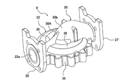
- FIG. 2 is a perspective view of the pump casing 8
- FIG. 3 is a bottom view of the pump casing 8
- FIG. 4 is a side view of the pump casing 8.
- the rib 30 extends from the suction hydro portion 20 to the outside in the radial direction of the volute chamber 22b. As shown in FIG. 3, the suction port 20a, the rib 30, and the discharge port 22a are aligned in a straight line.
- the volute hydro portion 22 has an outer peripheral wall 35 surrounding the volute chamber 22b and a spiral wall 36 connected to the outer peripheral wall 35.
- the discharge port 22a is formed at the end of the spiral wall 36.
- the suction hydro portion 20 is connected to the central portion of the spiral wall 36.
- the rib 30 is connected to the outer surface of each of the suction hydro portion 20 and the volute hydro portion 22.
- the outermost peripheral surface 20b of the suction hydro portion 20 is curved toward the outside of the suction hydro portion 20.
- the rib 30 is smoothly connected to the curved outermost outer peripheral surface 20b of the suction hydro portion 20.
- the rib 30 has a curved outer edge 30A curved toward the inside of the rib 30.
- the curved outer edge 30A is smoothly connected to the outermost outer peripheral surface 20b of the suction hydro portion 20. That is, at the contact point C between the outermost peripheral surface 20b of the suction hydro portion 20 and the curved outer edge 30A of the rib 30, the tangent line T1 on the curved outer edge 30A of the rib 30 and the tangent line T2 on the outermost peripheral surface 20b of the suction hydro portion 20 , Match.
- the ratio (R1 / R2 ⁇ 100) of the radius of curvature R1 of the rib 30 to the radius of curvature R2 of the outermost peripheral surface 20b of the suction hydro portion 20 is 20% or more.
- the ratio of the radius of curvature R1 to the radius of curvature R2 is 50% or more, more preferably 100% or more.
- the radius of curvature R1 is equal to the radius of curvature R2.
- the radius of curvature R1 may be larger than the radius of curvature R2. As the radius of curvature R1 increases, the curved outer edge 30A of the rib 30 approaches a straight line.
- the upper limit of the radius of curvature R1 that is, the upper limit of the ratio of the radius of curvature R1 to the radius of curvature R2 is not particularly limited.
- the curved outer edge 30A of the rib 30 may have a shape as close to a straight line as possible.
- the center O1 of the curvature circle of the curved outer edge 30A of the rib 30 is located outside the pump casing 8, and the center O2 of the curvature circle of the outermost peripheral surface 20b of the suction hydro portion 20 is located inside the pump casing 8. ..
- the radius of curvature R1 of the curved outer edge 30A of the rib 30 is the same as the radius of curvature R2 of the outermost peripheral surface 20b of the suction hydro portion 20.
- the curved outer edge 30A of the rib 30 has a similar shape to the outermost outer peripheral surface 20b of the suction hydro portion 20.
- the portion where the stress is concentrated can be kept away from the suction hydro portion 20.
- the location where the stress is concentrated is at the position indicated by the reference numeral Y in FIG. 4, and is separated from the suction hydro portion 20. Therefore, even if a crack occurs in the curved outer edge 30A of the rib 30 due to stress concentration, the crack propagates inside the rib 30 and hardly reaches the suction hydro portion 20. That is, the cracks are less likely to reach the suction hydro portion 20 by the height of the rib 30. As a result, it is possible to prevent the suction hydro portion 20 itself from being cracked.
- the pump device of this embodiment is an in-line pump device in which the suction port 20a and the discharge port 22a are aligned in a straight line.
- the in-line pump device is a type of pump device that is installed in the middle of piping. That is, by connecting the suction flange 27 to the suction pipe (not shown) and the discharge flange 28 to the discharge pipe (not shown), the entire pump device is supported by the suction pipe and the discharge pipe. Will be installed. In such an installation, a bending moment is applied to the pump casing 8.
- one end of the curved outer edge 30A of the rib 30 is connected to the outermost peripheral surface 20b of the suction hydro portion 20, and the other end of the curved outer edge 30A of the rib 30 is connected to the discharge flange 28.
- the rib 30 can give sufficient mechanical strength to the pump casing 8 with respect to the bending moment.
- the rib 30 has a curved outer edge 30A that is smoothly connected to the outermost peripheral surface 20b of the suction hydro portion 20, the other portion of the rib 30 does not have to be curved. That is, the entire outer edge of the rib 30 does not have to be curved inward.
- the rib 30 may have the curved outer edge 30A and a linear outer edge 30B connected to the curved outer edge 30A.
- the rib 30 may have a notch 30C formed in the curved outer edge 30A.
- the rib 30 may not be connected to the discharge flange 28.
- the end of the rib 30 may be connected to the spiral wall 36 of the volute hydro portion 22.
- the rib 30 has a curved outer edge 30A smoothly connected to the outermost peripheral surface 20b of the suction hydro portion 20, and the curvature of the curved outer edge 30A is shown in FIG. It is the same as the embodiment described with reference to. Therefore, the ribs 30 shown in FIGS. 5 to 7 can keep the stress-concentrated portion away from the suction hydro portion 20.
- the present invention can be used for a reinforcing structure of a pump casing that houses an impeller.
- the present invention can also be applied to a pump device provided with such a pump casing.
Landscapes
- Engineering & Computer Science (AREA)
- Mechanical Engineering (AREA)
- General Engineering & Computer Science (AREA)
- Structures Of Non-Positive Displacement Pumps (AREA)
Abstract
本発明は、羽根車を収容するポンプケーシングの補強構造に関するものである。ポンプケーシング(8)は、吐出し口(22a)を有するボリュートハイドロ部(22)と、吸込み口(20a)を有する吸込みハイドロ部(20)と、ボリュートハイドロ部(22)および吸込みハイドロ部(20)のそれぞれの外面に接続されたリブ(30)を備える。リブ(30)は、該リブ(30)の内側に向かって湾曲した湾曲外縁(30A)を有しており、湾曲外縁(30A)は、吸込みハイドロ部(20)の最外周面(20b)に滑らかに接続されている。吸込みハイドロ部(20)の最外周面(20b)の曲率半径(R2)に対する、湾曲外縁(30A)の曲率半径(R1)の比率は、20%以上である。
Description
本発明は、ポンプケーシングに関し、特に羽根車を収容するポンプケーシングの補強構造に関するものである。また、本発明は、そのようなポンプケーシングを備えたポンプ装置に関するものである。
渦巻ポンプは、羽根車をポンプケーシング内で回転させることにより液体をポンプケーシング内で昇圧し、該昇圧された液体を吐出し口から外部に吐き出す。液体の圧力がポンプケーシングに作用すると、ポンプケーシングの一部に高い応力が発生し、ポンプケーシングが変形する。ポンプケーシングが変形すると、昇圧された液体がポンプケーシングから漏れる場合がある。そのため、ポンプケーシングの変形を一定以下にするための強度がポンプケーシングには要求される。
渦巻室を持つポンプケーシングの形状は複雑であるため、ポンプケーシングは、一般的に、鋳造で製作される。ポンプケーシングの強度を高めるために、ポンプケーシング全体の肉厚を厚くすると、ポンプケーシングの重量が増加してしまい、結果的に、渦巻ポンプ全体の重量が増加してしまう。
一方、ポンプケーシングを薄くすると、ポンプケーシングの機械的強度が低下し、渦巻ポンプは耐水圧試験に合格することができないことがある。この耐水圧試験は、渦巻ポンプからの水漏れを検査する目的で行われる。具体的には、ポンプケーシングから羽根車や回転軸を取り外した状態で、ポンプケーシングの吸込み口、吐出し口を含むすべての開口部を閉じて密閉空間をポンプケーシング内に形成し、この密閉空間を、ポンプの最高吐出し圧力の1.5倍の圧力の水で満たし、そのままの状態で3分間以上放置し、水漏れおよびポンプケーシングの変形を検査する。
上記耐水圧試験に加え、インチング試験が行われることもある。このインチング試験は、ポンプケーシング内において圧力なしの状態からある数値まで圧力を上げることを繰り返し、ポンプケーシングからの水漏れを検査する試験である。このように、ポンプケーシングには、安全な運転を確保する観点から高い強度を持つことが要求される。
そこで、ポンプケーシングの強度を高めるために、ポンプケーシングの外周面にリブが設けられる。図8は、従来のポンプケーシングの一例を示す断面図である。ポンプケーシング200は、吸込み口201aを有する吸込みハイドロ部201と、羽根車が収容されるボリュート室202aおよび吐出し口202bを有するボリュートハイドロ部202を有している。リブ205は、吸込みハイドロ部201から吐出しフランジ206まで延びている。このようなリブ205は、ポンプケーシング200の断面二次モーメントを高め、ポンプケーシング200の強度を向上させることができる。
しかしながら、ポンプケーシング200内に高い圧力が加えられたときに、図8の符号Xで示す接続部に応力が集中することが、応力解析により分かった。この接続部Xは、リブ205と吸込みハイドロ部201とが接続される部分である。この接続部Xに高い応力が集中すると、接続部Xの外面に亀裂が生じる。亀裂は吸込みハイドロ部201の内側に向かって進展し、やがて吸込みハイドロ部201の内面に達する。ポンプケーシング200の内側にまで達した亀裂は、ポンプケーシング200からの液漏れを引き起こす。特に、ポンプの起動および停止が頻繁に起こる環境下では、亀裂の進展が早く進み、ポンプケーシング200の寿命が短くなってしまう。
そこで、本発明は、リブに亀裂が生じても、亀裂がポンプケーシングの内側まで達しにくくして、液漏れを防ぐことができるポンプケーシングを提供する。また、本発明は、そのようなポンプケーシングを備えたポンプ装置を提供する。
一態様では、羽根車を収容するためのボリュート室、および吐出し口を有するボリュートハイドロ部と、前記ボリュート室に連通する吸込み口を有する吸込みハイドロ部と、前記ボリュートハイドロ部および前記吸込みハイドロ部のそれぞれの外面に接続されたリブを備え、前記リブは、該リブの内側に向かって湾曲した湾曲外縁を有しており、前記湾曲外縁は、前記吸込みハイドロ部の最外周面に滑らかに接続されており、前記吸込みハイドロ部の前記最外周面の曲率半径に対する、前記湾曲外縁の曲率半径の比率は、20%以上である、ポンプケーシングが提供される。
一態様では、前記リブの前記湾曲外縁と前記吸込みハイドロ部の前記最外周面との接点において、前記湾曲外縁上の接線と、前記吸込みハイドロ部の前記最外周面上の接線は、一致する。
一態様では、前記リブは、前記吐出し口の周りを囲む吐出しフランジに接続されている。
一態様では、前記リブの前記湾曲外縁は、前記吸込みハイドロ部から前記吐出しフランジまで延びている。
一態様では、前記リブは、前記吐出し口の周りを囲む吐出しフランジに接続されている。
一態様では、前記リブの前記湾曲外縁は、前記吸込みハイドロ部から前記吐出しフランジまで延びている。
一態様では、羽根車と、前記羽根車に連結された電動機と、前記羽根車を収容する上記ポンプケーシングを備えているポンプ装置が提供される。
本発明によれば、応力は、リブと吸込みハイドロ部との接続部から離れた位置に集中する。言い換えれば、上記曲率半径の湾曲外縁を持つリブは、応力が集中する箇所を吸込みハイドロ部から遠ざけることができる。したがって、仮に応力集中に起因してリブの湾曲外縁に亀裂が生じても、亀裂はリブの内側に進展し、吸込みハイドロ部には到達しにくい。すなわち、リブの高さ分だけ亀裂は吸込みハイドロ部には達しにくくなる。結果として、吸込みハイドロ部自体に亀裂が生じることを防ぐことができる。
以下、本発明の実施形態について図面を参照して説明する。
図1は、ポンプ装置の一実施形態を示す断面図である。本実施形態のポンプ装置は、吸込み口および吐出し口が一直線上に並ぶインラインポンプ装置である。このタイプのポンプ装置は、脚部を持たず、ポンプ装置の全体は、吸込みフランジおよび吐出しフランジに連結された配管によって支持される。
図1は、ポンプ装置の一実施形態を示す断面図である。本実施形態のポンプ装置は、吸込み口および吐出し口が一直線上に並ぶインラインポンプ装置である。このタイプのポンプ装置は、脚部を持たず、ポンプ装置の全体は、吸込みフランジおよび吐出しフランジに連結された配管によって支持される。
ポンプ装置は、電動機1と、電動機1に軸継手3を介して連結された回転軸2と、回転軸2に固定された羽根車5と、羽根車5を収容するポンプケーシング8を備えている。羽根車5は、遠心羽根車である。羽根車2は、回転軸2を介して電動機1に連結されており、回転軸2および羽根車5は、電動機1によって一体に回転される。
電動機1とポンプケーシング8との間には、ケーシングカバー12およびモータ台14が配置されている。ポンプケーシング8の開口は、ケーシングカバー12によって塞がれている。モータ台14はケーシングカバー12に固定され、電動機1はモータ台14に固定されている。ポンプケーシング8は、鋳物である。
ポンプケーシング8は、吸込み口20aを有する吸込みハイドロ部20と、吐出し口22aおよびボリュート室22bを有するボリュートハイドロ部22を備えている。羽根車5はボリュート室22b内に配置されている。吸込み口20aおよび吐出し口22aは、ボリュート室22bに連通している。すなわち、吸込みハイドロ部20は、吸込み口20aおよびボリュート室22bに接続された吸込み流路24を有しており、吸込み口20aは吸込み流路24を通じてボリュート室22bに連通している。ボリュートハイドロ部22は、ボリュート室22bおよび吐出し口22aに接続された吐出し流路25を有しており、吐出し口22aは吐出し流路25を通じてボリュート室22bに連通している。
電動機1が羽根車5を回転させると、液体は、吸込みハイドロ部20の吸込み口20aから吸込み流路24を通ってボリュート室22b内の羽根車5に流れ込む。回転する羽根車5は液体に速度エネルギーを付与し、ボリュート室22bを流れる液体の速度エネルギーは圧力に変換される。昇圧された液体は、ボリュートハイドロ部22の吐出し流路25を通って吐出し口22aから吐き出される。
ポンプケーシング8は、吸込み口20aの周りを囲む吸込みフランジ27と、吐出し口22aの周りを囲む吐出しフランジ28を有している。吸込み口20aおよび吐出し口22aは、一直線上に並んでいる。ポンプケーシング8は脚部を持たず、ポンプ装置の全体は、吸込みフランジ27および吐出しフランジ28に接続された配管(図示せず)によって支持される。吸込み口20aおよび吐出し口22aが一直線上に並んだポンプ装置は、配管の途中に組み込むことができるインラインポンプ装置と呼ばれる。
吸込みハイドロ部20の最外周面20bは、吸込み流路24の形状に沿って外側に湾曲している。ポンプケーシング8は、吸込みハイドロ部20の最外周面20bに滑らかに接続されたリブ30を備えている。このリブ30は、ポンプケーシング8の強度を高めるために設けられている。
図2は、ポンプケーシング8の斜視図であり、図3は、ポンプケーシング8の底面図であり、図4は、ポンプケーシング8の側面図である。リブ30は、吸込みハイドロ部20からボリュート室22bの半径方向外側に延びている。図3に示すように、吸込み口20a、リブ30、および吐出し口22aは、一直線上に並んでいる。
ボリュートハイドロ部22は、ボリュート室22bを囲む外周壁35と、外周壁35に接続された渦巻壁36を有している。吐出し口22aは、渦巻壁36の端部に形成されている。吸込みハイドロ部20は、渦巻壁36の中央部に接続されている。
リブ30は、吸込みハイドロ部20とボリュートハイドロ部22のそれぞれの外面に接続されている。吸込みハイドロ部20の最外周面20bは、吸込みハイドロ部20の外側に向かって湾曲している。リブ30は、吸込みハイドロ部20の湾曲した最外周面20bに滑らかに接続されている。
図4に示すように、リブ30は、該リブ30の内側に向かって湾曲した湾曲外縁30Aを有している。この湾曲外縁30Aは、吸込みハイドロ部20の最外周面20bに滑らかに接続されている。すなわち、吸込みハイドロ部20の最外周面20bとリブ30の湾曲外縁30Aとの接点Cにおいて、リブ30の湾曲外縁30A上の接線T1と、吸込みハイドロ部20の最外周面20b上の接線T2は、一致する。
吸込みハイドロ部20の最外周面20bの曲率半径R2に対する、リブ30の曲率半径R1の比率(R1/R2×100)は、20%以上である。好ましくは、曲率半径R2に対する曲率半径R1の比率は、50%以上、より好ましくは100%以上である。曲率半径R2に対する曲率半径R1の比率が100%であるとき、曲率半径R1は曲率半径R2に等しい。曲率半径R1は曲率半径R2よりも大きくてもよい。曲率半径R1が大きくなるにつれて、リブ30の湾曲外縁30Aは直線に近づく。曲率半径R1の上限、すなわち曲率半径R2に対する曲率半径R1の比率の上限は、特に限定されない。言い換えれば、リブ30の湾曲外縁30Aが、吸込みハイドロ部20の最外周面20bに滑らかに接続されている限り、湾曲外縁30Aは限りなく直線に近い形状であってもよい。
リブ30の湾曲外縁30Aの曲率円の中心O1は、ポンプケーシング8の外側に位置し、吸込みハイドロ部20の最外周面20bの曲率円の中心O2は、ポンプケーシング8の内側に位置している。一実施形態では、リブ30の湾曲外縁30Aの曲率半径R1は、吸込みハイドロ部20の最外周面20bの曲率半径R2と同じである。あるいは、リブ30の湾曲外縁30Aは、吸込みハイドロ部20の最外周面20bと相似形である。
曲率半径R2に対する曲率半径R1の比率が20%以上であるとき、応力が集中する箇所を吸込みハイドロ部20から遠ざけることができる。応力解析によれば、応力が集中する箇所は、図4の符号Yで示す位置にあり、吸込みハイドロ部20から離れている。したがって、仮に応力集中に起因してリブ30の湾曲外縁30Aに亀裂が生じても、亀裂はリブ30の内側に進展し、吸込みハイドロ部20には到達しにくい。すなわち、リブ30の高さ分だけ亀裂は吸込みハイドロ部20には達しにくくなる。結果として、吸込みハイドロ部20自体に亀裂が生じることを防ぐことができる。
本実施形態のポンプ装置は、吸込み口20aと吐出し口22aが一直線上に並ぶインラインポンプ装置である。インラインポンプ装置は、配管の途中に組み込まれるタイプのポンプ装置である。すなわち、吸込みフランジ27を吸込み配管(図示せず)に接続し、吐出しフランジ28を吐出し配管(図示せず)に接続することで、ポンプ装置の全体を吸込み配管および吐出し配管で支持するように設置される。このような設置では、ポンプケーシング8には曲げモーメントが加わる。
本実施形態では、リブ30の湾曲外縁30Aの一端は吸込みハイドロ部20の最外周面20bに接続され、リブ30の湾曲外縁30Aの他端は吐出しフランジ28に接続されている。このように、リブ30は吸込みハイドロ部20から吐出しフランジ28まで延びているので、リブ30は曲げモーメントに対して十分な機械的強度をポンプケーシング8に与えることができる。
リブ30は、吸込みハイドロ部20の最外周面20bに滑らかに接続された湾曲外縁30Aを有していれば、リブ30の他の部分は湾曲していなくてもよい。すなわち、リブ30の外縁の全体が内側に湾曲していなくてもよい。例えば、図5に示すように、リブ30は、上記湾曲外縁30Aと、湾曲外縁30Aに接続された直線状の外縁30Bを有してもよい。他の例では、図6に示すように、リブ30は、上記湾曲外縁30Aに形成された切り欠き30Cを有してもよい。
ポンプ装置の重量や、形状によっては、リブ30は吐出しフランジ28に接続されていなくてもよい。例えば、図7に示すように、リブ30の端部はボリュートハイドロ部22の渦巻壁36に接続されてもよい。
図5乃至図7に示す実施形態においても、リブ30は、吸込みハイドロ部20の最外周面20bに滑らかに接続された湾曲外縁30Aを有しており、その湾曲外縁30Aの曲率は図4を参照して説明した実施形態と同じである。したがって、図5乃至図7に示すリブ30は、応力が集中する箇所を、吸込みハイドロ部20から遠ざけることができる。
上述した実施形態は、本発明が属する技術分野における通常の知識を有する者が本発明を実施できることを目的として記載されたものである。上記実施形態の種々の変形例は、当業者であれば当然になしうることであり、本発明の技術的思想は他の実施形態にも適用しうる。したがって、本発明は、記載された実施形態に限定されることはなく、特許請求の範囲によって定義される技術的思想に従った最も広い範囲に解釈されるものである。
本発明は、羽根車を収容するポンプケーシングの補強構造に利用可能である。また、本発明は、そのようなポンプケーシングを備えたポンプ装置に利用可能である。
1 電動機
2 回転軸
3 軸継手
5 羽根車
8 ポンプケーシング
12 ケーシングカバー
14 モータ台
20 吸込みハイドロ部
20a 吸込み口
20b 最外周面
22a 吐出し口
22b ボリュート室
22 ボリュートハイドロ部
24 吸込み流路
25 吐出し流路
27 吸込みフランジ
28 吐出しフランジ
30 リブ
30A 湾曲外縁
35 外周壁
36 渦巻壁
T1 接線
T2 接線
R1 曲率半径
R2 曲率半径
2 回転軸
3 軸継手
5 羽根車
8 ポンプケーシング
12 ケーシングカバー
14 モータ台
20 吸込みハイドロ部
20a 吸込み口
20b 最外周面
22a 吐出し口
22b ボリュート室
22 ボリュートハイドロ部
24 吸込み流路
25 吐出し流路
27 吸込みフランジ
28 吐出しフランジ
30 リブ
30A 湾曲外縁
35 外周壁
36 渦巻壁
T1 接線
T2 接線
R1 曲率半径
R2 曲率半径
Claims (5)
- 羽根車を収容するためのボリュート室、および吐出し口を有するボリュートハイドロ部と、
前記ボリュート室に連通する吸込み口を有する吸込みハイドロ部と、
前記ボリュートハイドロ部および前記吸込みハイドロ部のそれぞれの外面に接続されたリブを備え、
前記リブは、該リブの内側に向かって湾曲した湾曲外縁を有しており、
前記湾曲外縁は、前記吸込みハイドロ部の最外周面に滑らかに接続されており、
前記吸込みハイドロ部の前記最外周面の曲率半径に対する、前記湾曲外縁の曲率半径の比率は、20%以上である、ポンプケーシング。 - 前記リブの前記湾曲外縁と前記吸込みハイドロ部の前記最外周面との接点において、前記湾曲外縁上の接線と、前記吸込みハイドロ部の前記最外周面上の接線は、一致する、請求項1に記載のポンプケーシング。
- 前記リブは、前記吐出し口の周りを囲む吐出しフランジに接続されている、前記請求項1または2に記載のポンプケーシング。
- 前記リブの前記湾曲外縁は、前記吸込みハイドロ部から前記吐出しフランジまで延びている、請求項3に記載のポンプケーシング。
- 羽根車と、
前記羽根車に連結された電動機と、
前記羽根車を収容する、請求項1乃至4のいずれか一項に記載のポンプケーシングを備えているポンプ装置。
Priority Applications (3)
| Application Number | Priority Date | Filing Date | Title |
|---|---|---|---|
| US17/755,047 US20220381261A1 (en) | 2019-11-05 | 2020-11-02 | Pump casing and pump apparatus |
| DK20885133.7T DK4056858T3 (da) | 2019-11-05 | 2020-11-02 | Pumpehus og pumpeenhed |
| EP20885133.7A EP4056858B1 (en) | 2019-11-05 | 2020-11-02 | Pump casing and pump device |
Applications Claiming Priority (2)
| Application Number | Priority Date | Filing Date | Title |
|---|---|---|---|
| JP2019200645A JP7350625B2 (ja) | 2019-11-05 | 2019-11-05 | ポンプケーシングおよびポンプ装置 |
| JP2019-200645 | 2019-11-05 |
Publications (1)
| Publication Number | Publication Date |
|---|---|
| WO2021090795A1 true WO2021090795A1 (ja) | 2021-05-14 |
Family
ID=75847985
Family Applications (1)
| Application Number | Title | Priority Date | Filing Date |
|---|---|---|---|
| PCT/JP2020/041018 Ceased WO2021090795A1 (ja) | 2019-11-05 | 2020-11-02 | ポンプケーシングおよびポンプ装置 |
Country Status (5)
| Country | Link |
|---|---|
| US (1) | US20220381261A1 (ja) |
| EP (1) | EP4056858B1 (ja) |
| JP (1) | JP7350625B2 (ja) |
| DK (1) | DK4056858T3 (ja) |
| WO (1) | WO2021090795A1 (ja) |
Families Citing this family (3)
| Publication number | Priority date | Publication date | Assignee | Title |
|---|---|---|---|---|
| JP1689844S (ja) * | 2020-11-12 | 2021-07-12 | ||
| JP1689843S (ja) * | 2020-11-12 | 2021-07-12 | ||
| WO2022230321A1 (ja) | 2021-04-28 | 2022-11-03 | 日本たばこ産業株式会社 | エアロゾル生成装置、制御方法及びコンピュータプログラム |
Citations (4)
| Publication number | Priority date | Publication date | Assignee | Title |
|---|---|---|---|---|
| JP2007291921A (ja) | 2006-04-24 | 2007-11-08 | Ebara Corp | 立型遠心ポンプ |
| JP2011137422A (ja) * | 2009-12-28 | 2011-07-14 | Ebara Corp | ポンプ用羽根車及びそれを備えた水中ポンプ |
| JP2013024149A (ja) * | 2011-07-22 | 2013-02-04 | Hitachi Industrial Equipment Systems Co Ltd | ポンプ装置 |
| EP3211245A1 (en) * | 2016-02-23 | 2017-08-30 | Sulzer Management AG | A volute casing for a centrifugal pump |
Family Cites Families (9)
| Publication number | Priority date | Publication date | Assignee | Title |
|---|---|---|---|---|
| ES2349239B1 (es) * | 2008-02-08 | 2011-10-19 | Jose Lorengo Bugallo | Una bomba centrifuga normalizada formada con piezas de fabricacion estandar (curvas o codos y bridas), soldadura y mecanizado y su procedimiento de fabricacion. |
| ES2528237T3 (es) * | 2008-06-13 | 2015-02-06 | Weir Minerals Australia Ltd | Mejoras referentes a conjuntos de estanqueidad para bombas |
| CN103688450B (zh) * | 2011-07-22 | 2016-10-26 | 株式会社日立产机系统 | 泵装置 |
| EP2626567B2 (de) * | 2012-02-08 | 2019-10-16 | Grundfos Holding A/S | Pumpengehäuse |
| JP3180240U (ja) * | 2012-07-06 | 2012-12-13 | 幸雄 大田 | 横軸渦巻ポンプ |
| CN104235070A (zh) * | 2013-06-13 | 2014-12-24 | 德昌电机(深圳)有限公司 | 泵壳及具有该泵壳的泵 |
| CN204511983U (zh) * | 2015-01-09 | 2015-07-29 | 邢台科创重工机械有限公司 | 一种立式管道泵体 |
| US11732719B2 (en) * | 2017-01-27 | 2023-08-22 | S.A. Armstrong Limited | Dual body variable duty performance optimizing pump unit |
| JP6873031B2 (ja) * | 2017-12-26 | 2021-05-19 | 株式会社荏原製作所 | 渦巻きポンプ用ケーシング及び渦巻きポンプ |
-
2019
- 2019-11-05 JP JP2019200645A patent/JP7350625B2/ja active Active
-
2020
- 2020-11-02 EP EP20885133.7A patent/EP4056858B1/en active Active
- 2020-11-02 US US17/755,047 patent/US20220381261A1/en not_active Abandoned
- 2020-11-02 WO PCT/JP2020/041018 patent/WO2021090795A1/ja not_active Ceased
- 2020-11-02 DK DK20885133.7T patent/DK4056858T3/da active
Patent Citations (4)
| Publication number | Priority date | Publication date | Assignee | Title |
|---|---|---|---|---|
| JP2007291921A (ja) | 2006-04-24 | 2007-11-08 | Ebara Corp | 立型遠心ポンプ |
| JP2011137422A (ja) * | 2009-12-28 | 2011-07-14 | Ebara Corp | ポンプ用羽根車及びそれを備えた水中ポンプ |
| JP2013024149A (ja) * | 2011-07-22 | 2013-02-04 | Hitachi Industrial Equipment Systems Co Ltd | ポンプ装置 |
| EP3211245A1 (en) * | 2016-02-23 | 2017-08-30 | Sulzer Management AG | A volute casing for a centrifugal pump |
Non-Patent Citations (1)
| Title |
|---|
| See also references of EP4056858A4 |
Also Published As
| Publication number | Publication date |
|---|---|
| JP2021076017A (ja) | 2021-05-20 |
| US20220381261A1 (en) | 2022-12-01 |
| EP4056858B1 (en) | 2026-02-11 |
| EP4056858A1 (en) | 2022-09-14 |
| JP7350625B2 (ja) | 2023-09-26 |
| EP4056858A4 (en) | 2023-12-06 |
| DK4056858T3 (da) | 2026-03-23 |
Similar Documents
| Publication | Publication Date | Title |
|---|---|---|
| WO2021090795A1 (ja) | ポンプケーシングおよびポンプ装置 | |
| US9239056B2 (en) | Pump impeller and submersible pump having such pump impeller | |
| US11441576B2 (en) | Double-suction centrifugal pump | |
| US8272838B2 (en) | Impeller and pump including the same | |
| JP2015007423A (ja) | 循環ポンプ | |
| JP6184955B2 (ja) | 軸推力を生じる両吸込羽根車を備えるポンプ | |
| KR200477242Y1 (ko) | 토출력을 증대시킨 수중펌프 | |
| US2046226A (en) | Centrifugal pump | |
| JP2013011241A (ja) | 輪切形多段ポンプ | |
| KR200420955Y1 (ko) | 다단식 펌프의 와류방지 가이드 장치 | |
| US20130156545A1 (en) | Dual-flow centrifugal pump | |
| JP2017031965A (ja) | 両吸込渦巻ポンプ | |
| KR102313450B1 (ko) | 원심펌프 | |
| JP7132825B2 (ja) | ポンプケーシングおよびポンプ装置 | |
| CN205243947U (zh) | 泵壳体 | |
| KR102316724B1 (ko) | 원심펌프 | |
| AU2019203725A1 (en) | Impeller with axially curving vane extensions to prevent airlock | |
| US3071077A (en) | Centrifugal pump | |
| JP6711806B2 (ja) | 片吸込立軸ポンプ | |
| NO163916B (no) | Flertrinns sentrifugalpumpe med lukket impeller. | |
| JP6764328B2 (ja) | ケーシングおよびターボ機械 | |
| JP2017044182A (ja) | 両吸込渦巻ポンプ | |
| JP7330508B2 (ja) | 羽根車及び水中ポンプ | |
| JP2017044181A (ja) | 両吸込渦巻ポンプ | |
| JP2020076323A (ja) | 戻り羽根組立体および多段ポンプ |
Legal Events
| Date | Code | Title | Description |
|---|---|---|---|
| 121 | Ep: the epo has been informed by wipo that ep was designated in this application |
Ref document number: 20885133 Country of ref document: EP Kind code of ref document: A1 |
|
| NENP | Non-entry into the national phase |
Ref country code: DE |
|
| ENP | Entry into the national phase |
Ref document number: 2020885133 Country of ref document: EP Effective date: 20220607 |
|
| WWG | Wipo information: grant in national office |
Ref document number: 2020885133 Country of ref document: EP |