WO2021092437A1 - Systems, methods, and machines for automated screw anchor driving - Google Patents
Systems, methods, and machines for automated screw anchor driving Download PDFInfo
- Publication number
- WO2021092437A1 WO2021092437A1 PCT/US2020/059478 US2020059478W WO2021092437A1 WO 2021092437 A1 WO2021092437 A1 WO 2021092437A1 US 2020059478 W US2020059478 W US 2020059478W WO 2021092437 A1 WO2021092437 A1 WO 2021092437A1
- Authority
- WO
- WIPO (PCT)
- Prior art keywords
- screw anchor
- embedment depth
- controller
- machine
- mast
- Prior art date
- Legal status (The legal status is an assumption and is not a legal conclusion. Google has not performed a legal analysis and makes no representation as to the accuracy of the status listed.)
- Ceased
Links
Classifications
-
- E—FIXED CONSTRUCTIONS
- E02—HYDRAULIC ENGINEERING; FOUNDATIONS; SOIL SHIFTING
- E02D—FOUNDATIONS; EXCAVATIONS; EMBANKMENTS; UNDERGROUND OR UNDERWATER STRUCTURES
- E02D5/00—Bulkheads, piles, or other structural elements specially adapted to foundation engineering
- E02D5/22—Piles
- E02D5/56—Screw piles
-
- E—FIXED CONSTRUCTIONS
- E02—HYDRAULIC ENGINEERING; FOUNDATIONS; SOIL SHIFTING
- E02D—FOUNDATIONS; EXCAVATIONS; EMBANKMENTS; UNDERGROUND OR UNDERWATER STRUCTURES
- E02D33/00—Testing foundations or foundation structures
-
- E—FIXED CONSTRUCTIONS
- E02—HYDRAULIC ENGINEERING; FOUNDATIONS; SOIL SHIFTING
- E02D—FOUNDATIONS; EXCAVATIONS; EMBANKMENTS; UNDERGROUND OR UNDERWATER STRUCTURES
- E02D5/00—Bulkheads, piles, or other structural elements specially adapted to foundation engineering
- E02D5/74—Means for anchoring structural elements or bulkheads
- E02D5/80—Ground anchors
- E02D5/801—Ground anchors driven by screwing
-
- E—FIXED CONSTRUCTIONS
- E02—HYDRAULIC ENGINEERING; FOUNDATIONS; SOIL SHIFTING
- E02D—FOUNDATIONS; EXCAVATIONS; EMBANKMENTS; UNDERGROUND OR UNDERWATER STRUCTURES
- E02D7/00—Methods or apparatus for placing sheet pile bulkheads, piles, mouldpipes, or other moulds
- E02D7/22—Placing by screwing down
-
- F—MECHANICAL ENGINEERING; LIGHTING; HEATING; WEAPONS; BLASTING
- F24—HEATING; RANGES; VENTILATING
- F24S—SOLAR HEAT COLLECTORS; SOLAR HEAT SYSTEMS
- F24S25/00—Arrangement of stationary mountings or supports for solar heat collector modules
- F24S25/10—Arrangement of stationary mountings or supports for solar heat collector modules extending in directions away from a supporting surface
- F24S25/12—Arrangement of stationary mountings or supports for solar heat collector modules extending in directions away from a supporting surface using posts in combination with upper profiles
-
- F—MECHANICAL ENGINEERING; LIGHTING; HEATING; WEAPONS; BLASTING
- F24—HEATING; RANGES; VENTILATING
- F24S—SOLAR HEAT COLLECTORS; SOLAR HEAT SYSTEMS
- F24S25/00—Arrangement of stationary mountings or supports for solar heat collector modules
- F24S25/60—Fixation means, e.g. fasteners, specially adapted for supporting solar heat collector modules
- F24S25/61—Fixation means, e.g. fasteners, specially adapted for supporting solar heat collector modules for fixing to the ground or to building structures
- F24S25/617—Elements driven into the ground, e.g. anchor-piles; Foundations for supporting elements; Connectors for connecting supporting structures to the ground or to flat horizontal surfaces
-
- H—ELECTRICITY
- H02—GENERATION; CONVERSION OR DISTRIBUTION OF ELECTRIC POWER
- H02S—GENERATION OF ELECTRIC POWER BY CONVERSION OF INFRARED RADIATION, VISIBLE LIGHT OR ULTRAVIOLET LIGHT, e.g. USING PHOTOVOLTAIC [PV] MODULES
- H02S20/00—Supporting structures for PV modules
- H02S20/10—Supporting structures directly fixed to the ground
-
- H—ELECTRICITY
- H02—GENERATION; CONVERSION OR DISTRIBUTION OF ELECTRIC POWER
- H02S—GENERATION OF ELECTRIC POWER BY CONVERSION OF INFRARED RADIATION, VISIBLE LIGHT OR ULTRAVIOLET LIGHT, e.g. USING PHOTOVOLTAIC [PV] MODULES
- H02S20/00—Supporting structures for PV modules
- H02S20/30—Supporting structures being movable or adjustable, e.g. for angle adjustment
- H02S20/32—Supporting structures being movable or adjustable, e.g. for angle adjustment specially adapted for solar tracking
-
- E—FIXED CONSTRUCTIONS
- E02—HYDRAULIC ENGINEERING; FOUNDATIONS; SOIL SHIFTING
- E02D—FOUNDATIONS; EXCAVATIONS; EMBANKMENTS; UNDERGROUND OR UNDERWATER STRUCTURES
- E02D2600/00—Miscellaneous
- E02D2600/10—Miscellaneous comprising sensor means
-
- E—FIXED CONSTRUCTIONS
- E02—HYDRAULIC ENGINEERING; FOUNDATIONS; SOIL SHIFTING
- E02D—FOUNDATIONS; EXCAVATIONS; EMBANKMENTS; UNDERGROUND OR UNDERWATER STRUCTURES
- E02D7/00—Methods or apparatus for placing sheet pile bulkheads, piles, mouldpipes, or other moulds
- E02D7/02—Placing by driving
- E02D7/06—Power-driven drivers
- E02D7/10—Power-driven drivers with pressure-actuated hammer, i.e. the pressure fluid acting directly on the hammer structure
-
- E—FIXED CONSTRUCTIONS
- E02—HYDRAULIC ENGINEERING; FOUNDATIONS; SOIL SHIFTING
- E02D—FOUNDATIONS; EXCAVATIONS; EMBANKMENTS; UNDERGROUND OR UNDERWATER STRUCTURES
- E02D7/00—Methods or apparatus for placing sheet pile bulkheads, piles, mouldpipes, or other moulds
- E02D7/28—Placing of hollow pipes or mould pipes by means arranged inside the piles or pipes
-
- E—FIXED CONSTRUCTIONS
- E04—BUILDING
- E04H—BUILDINGS OR LIKE STRUCTURES FOR PARTICULAR PURPOSES; SWIMMING OR SPLASH BATHS OR POOLS; MASTS; FENCING; TENTS OR CANOPIES, IN GENERAL
- E04H12/00—Towers; Masts or poles; Chimney stacks; Water-towers; Methods of erecting such structures
- E04H12/22—Sockets or holders for poles or posts
- E04H12/2207—Sockets or holders for poles or posts not used
- E04H12/2215—Sockets or holders for poles or posts not used driven into the ground
- E04H12/2223—Sockets or holders for poles or posts not used driven into the ground by screwing
-
- F—MECHANICAL ENGINEERING; LIGHTING; HEATING; WEAPONS; BLASTING
- F24—HEATING; RANGES; VENTILATING
- F24S—SOLAR HEAT COLLECTORS; SOLAR HEAT SYSTEMS
- F24S30/00—Arrangements for moving or orienting solar heat collector modules
- F24S2030/10—Special components
- F24S2030/15—Bearings
-
- F—MECHANICAL ENGINEERING; LIGHTING; HEATING; WEAPONS; BLASTING
- F24—HEATING; RANGES; VENTILATING
- F24S—SOLAR HEAT COLLECTORS; SOLAR HEAT SYSTEMS
- F24S25/00—Arrangement of stationary mountings or supports for solar heat collector modules
- F24S25/70—Arrangement of stationary mountings or supports for solar heat collector modules with means for adjusting the final position or orientation of supporting elements in relation to each other or to a mounting surface; with means for compensating mounting tolerances
-
- F—MECHANICAL ENGINEERING; LIGHTING; HEATING; WEAPONS; BLASTING
- F24—HEATING; RANGES; VENTILATING
- F24S—SOLAR HEAT COLLECTORS; SOLAR HEAT SYSTEMS
- F24S30/00—Arrangements for moving or orienting solar heat collector modules
- F24S30/40—Arrangements for moving or orienting solar heat collector modules for rotary movement
- F24S30/42—Arrangements for moving or orienting solar heat collector modules for rotary movement with only one rotation axis
- F24S30/425—Horizontal axis
Definitions
- Utility-scale solar arrays are being developed all over the United States and around the world. Utility-scale arrays may span a few megawatts of capacity up to hundreds of megawatts and even gigawatts. Originally, these arrays were arranged as fixed tilt ground-mounted arrays, however, as solar panel prices have dropped, single-axis solar trackers are becoming the preferred utility-scale form factor. Single axis trackers are configured as North-South oriented rows of solar panels attached to a rotating torque tube. The torque tube is moved by a motor or other drive mechanism that slowly rotates multiple panels at once, so they move from East facing to West-facing to follow the sun's daily movement through the sky.
- H-pile solar foundations are typically installed using a pile driver, a percussive or vibratory tool that holds the pile at a plumb orientation and beats or vibrates the head of it repeatedly to incrementally drive it into the ground.
- pile driver is a piece of standard equipment, given their prevalence in the commercial solar industry, and the relatively small pile sizes used to support solar trackers, certain equipment makers have begun manufacturing pile driving machines specifically for the utility-scale solar industry.
- the Applicant of this disclosure has developed a novel truss-based foundation system to replace H-piles as the preferred foundation for single-axis trackers and other projects.
- this system is formed with a pair of screw anchors, above-ground upper legs and an adapter or truss cap that joins the free ends of the upper legs to complete the A-frame shaped assembly.
- the screw anchors are driven into the ground adjacent one another and at opposing angles in a common East-West plane to straddle an intended North- South line of the tracker row. They are open at both ends, enabling a mandrel, drill, or other tool to be extended through them while they are being driven.
- the truss cap is held in place by a jig on the machine and upper legs are sleeved over connectors on either side of the truss cap and at the upper end of each screw anchor.
- One or more crimpers are used to crimp the upper legs around the connectors preserving the truss cap's position.
- Figure 1A shows an exemplary screw anchor usable with various embodiments of the invention
- Figure IB is a detail view of a lead-in thread form of a screw anchor usable with various embodiments of the invention.
- Figure 2 is a front view of a portion of a single-axis tracker supported by truss foundation in accordance with various embodiments of the invention
- Figure 3 is a front view of a portion of another single-axis tracker supported by a truss foundation in accordance with various embodiments of the invention.
- Figure 4A is a perspective view of screw anchor driving machine according to various embodiments of the invention.
- Figure 4B is a partial front view of a mast of a screw anchor driving machine according to various embodiments of the invention.
- Figure 4C is another partial front view of a mast of a screw anchor driving machine according to various embodiments of the invention.
- Figure 5 is an isolation view of a mast of a screw anchor driving machine according to various embodiments of the invention.
- Figure 6 is an exemplary block circuit diagram of a control circuit for a screw anchor driving machine according various embodiments of the invention.
- Figure 7A is a diagram showing the geometry underpinning the automated leg length selection and screw anchor embedment calculation control processes according to various embodiments of the invention.
- Figure 7B is a diagram showing the geometry of the offset calculation for a screw the automated leg length selection and screw anchor embedment calculation control processes according to various embodiments of the invention.
- Figures 8A and 8B are diagrams illustrating the geometry underpinning the uplift correction control process according to various embodiments of the invention.
- Figure 9 is a flow chart detailing the steps of a method for determining upper leg length and actual embedment depth in with an automated screw anchor driving machine according to various embodiments of the invention.
- Figure 10 is a flow chart detailing the steps of a method for uplift correction with an automated screw anchor driving machine according to various embodiments of the invention.
- Figure 11 is a flow chart detailing the steps of a method for validating the pull-out strength of a driven screw anchor with an automated screw anchor driving machine according to various embodiments of the invention.
- FIG 1A shows an exemplary screw anchor 10 usable with various embodiments of the invention.
- Screw anchor 10 consists of a hollow, substantially uniform diameter rounded shaft 11 that is open at both ends with external threads 12 at one end and a driving collar 15 at the other.
- threads 12 may have a tapered profile, as seen for example, in Figure IB, so that their outside diameter increases moving up the shaft to create a lead-in.
- a taper such as this may help keep it on path while driving and also assist when driving into hard soils, caliche and even rock.
- the threads may also, in various embodiments, be tilted slightly upwards, that is, towards collar 15 to provide additional resistance to pull out.
- the length of screw anchor 10 may be variable depending on the desired depth of embedment (e.g., 1-2 meters). In the context of foundations for single-axis trackers and other axial solar arrays, embedment depth may be dictated by soil type, grade of land, torque tube height, and tracker type, among other factors.
- the inside diameter of the shaft may be between two and half and three inches and the thickness on the order of a few millimeters. It may be formed from galvanized alloy steel or other suitable material. In some cases, it may be coated with one or more additional anti-corrosion coatings such as fusion bonded epoxy, polyurethane, or acrylic, among others.
- Driving collar 15 may be a separate cast structure welded on to the upper end of shaft 11 or, alternatively, may be stamped, pressed, or otherwise formed in the upper end. Threads 12 may be welded to the outside of shaft 11 at the lower end, may be attached with bent tabs or, in some cases may even be stamped into the lower end. The threads enable screw anchor 10 be driven into supporting ground with a combination of torque and downforce. Screw anchor 10's open end allows a drill or other tool to be extended through it while the anchor is being driven into the ground to enable it to go through dense soil, rocks or other strata that might refuse the anchor by itself.
- the Applicant of this disclosure has proposed a new foundation system for axial solar arrays designed to replace H-piles.
- the foundation system relies on a pair of adjacent truss legs joined together above ground by a truss cap, adapter, bearing adapter or other structure to form a rigid A-frame-shaped structure.
- the angled legs translate lateral wind loads into axial forces of tension and compression rather than bending, allowing less steel to be used relative to H-piles.
- Variants of this foundation system known commercially as EARTH TRUSS, that are particularly well-suited for supporting single-axis trackers are shown in Figures 2 and 3.
- Figure 2 shows the system supporting a mechanically balanced single-axis tracker such as the NX Series of single-axis trackers manufactured and sold by NEXTracker Inc., of Fremont, CA.
- Figure 3 shows the system supporting a conventional generic single-axis tracker.
- EARTH TRUSS system 5 consists of a pair of adjacent screw anchors 10 that have been driven into supporting ground at angles to one another on the East and West sides of an intended North-South line of a tracker row. Once anchors 10 reach their target embedment depth, driving stops and truss cap or adapter 20/30 is held in place by a jig on the driving machine at the correct location to insure alignment with other truss caps or adapters in the same row. Then, upper legs 16 are sleeved over driving collars 15 of each anchor and respective connecting portions 21 of the truss cap to complete each truss leg 6.
- truss cap 20 provides a pair of spaced-apart pedestals that support the opposing feet of NEXTracker bearing housing assembly (BHA) 22.
- BHA 22 is a cardioid-shaped hoop with bearing 23 proximate to the cusp. It should be appreciated that other variants are possible as long as the bearing location enables the torque tube to be suspended from a bearing pin rather than rotating about its own axis.
- Bearing pin 24 is received within bearing 23 and extends out of both sides of BHA 22.
- a torque tube module bracket such as bracket 25 is suspended from either side of bearing pin 24.
- Brackets 25 support the torque tube (labeled "TT”) and also attach to the frame of at least one adjacent photovoltaic module or solar panel 40.
- the drive motor's drive axis is aligned with bearing pin 24 rather than the torque tube so that as the motor's output shaft rotates, the torque tube swings through an arc that is bounded on either side by the BHA 22.
- Figure 3 shows truss foundation 5 supporting a conventional single-axis tracker in which the torque tube rotates about its own axis.
- Truss cap 30 joins free ends of upper legs 16 to form a single pedestal that supports conventional bearing assembly 32.
- the torque tube is shown having a rounded cross section, it should be appreciated that in some cases, the tube may be faceted for increased strength with a bearing insert located between the outside of the torque tube and inside of bearing 33.
- Bearing 33 allows the torque tube to rotate about its own axis rather than swinging through an arc.
- the drive motor or row-to-row drive assembly imparts torque directly to the torque tube to adjust the orientation of modules 40.
- Module brackets such as bracket 34 rely on U-bolts or other common fasteners to attach the modules to the torque tube.
- upper legs 16 are joined to adapters 20/30 by sleeving the open end of each leg over respective connecting portions protecting away from the adapter. Then, crimps are formed over the overlapping portion of each upper leg 16 to lock the adapters into place. Crimps are also formed at the lower end of each upper leg 16 where it overlaps with the collar 15.
- the screw anchor driving machine may include a jig or other device that orients the adapter or truss cap so that it is level and aligned with a laser line to be at the at the same Y (East-West) and Z (up-down) position as every other adapter in the current row so that the EARTH TRUSS can be constructed in a fast, precise and repeatable manner.
- upper legs 16 may be crimped at each end, that is, at the areas of overlap with screw anchors 10 and with truss cap or adapter 20/30, thereby forming a rigid A-frame structure.
- assembling the EARTH TRUSS at the time the screw anchors are driven will obviate the need for later alignment steps, such as when the tracker components are installed.
- FIG. 4A this figure shows a screw anchor driving machine 100 manufactured by the applicant of this disclosure and known commercially as the truss driver in accordance with various exemplary embodiments of the invention.
- machine 100 is built on tracked chassis 110 with engine 112 and a hydraulic drive system. It should be appreciated that future versions of the machine may be electrically powered. Such modifications are within the spirit and scope of the invention. Also, it should be appreciated that machine 100 could instead ride on tires, on a combination of tires and tracks, on a floating barge, on rails or on another movable platform.
- machine 100 supports articulating mast 150 that in turn supports the elements used to drive screw anchors and assemble truss foundations.
- mast 150 is shown as an elongated boxed ladder-like structure extending approximately 15-25 feet in the long direction. It is connected to machine 100 by one or more hydraulic actuators.
- rotator 140 enables articulating mast 150 to move through an arc in at least one plane extending from the front to the back of the machine that spans approximately 90-degrees to allow mast 150 to go from a stowed position where the mast is substantially parallel to the machine's tracks, to an in-use position where the mast is substantially perpendicular to them. Therefore, when mast 150 is in the stowed position, its height is minimized, whereas when mast 150 is in-use, it will extend far above machine 100.
- rotator 140 is positioned in front of the one or more actuators connecting mast 150 to machine 100 so that the mast can rotate through a range of angles about a point of rotation (e.g., plus or minus 35-degrees from plumb) so that screw anchors may be driven into the ground at a range of angles while the machine remains stationary. This also decouples the driving angle from the left to right slope of the ground under the machine, allowing it to compensate for uneven terrain.
- a point of rotation e.g., plus or minus 35-degrees from plumb
- articulating mast 150 may move with respect to machine 100 so that it can self-level, adjust its pitch, and yaw, and move in the X, Y and Z-directions (where X is North-South, Y is East- West, and Z is vertical) without moving the machine. This may be accomplished with additional actuators or slides that move an intermediate frame that supports rotator 140 and that is positioned between the rotator and the machine.
- the components of machine 100 used to drive screw anchors are mounted on and move with the mast, as opposed to those used to position the mast.
- Parallel tracks 151 extending substantially the entire length of the mast define the plane that those components move in.
- the mast components may travel on wheels retained on a track running along the mast. Therefore, the mast's orientation dictates the vector or driving axis that screw anchors are driven along.
- the mast components include screw or rotary driver 154 with chuck 155 that connects to driving collar 15 of the screw anchor, and tool driver 156, located above the rotary driver.
- rotary driver 154 may be powered by hydraulics or by electric current.
- tool driver 156 may be powered by hydraulics, compressed air, electric current, or combinations of these.
- tool driver 156 is a hydraulic drifter that drives a tool consisting of shaft 158 and bit or tip 159 that extends along mast 150, passing through rotary driver 154, chuck 155 and the center of screw anchor 10.
- rotary driver 154 and tool driver 156 may be oriented concentrically on mast 150 in the direction of tracks 151 so that shaft 158 can pass through rotary driver 154 while it is driving a screw anchor. In this manner, the tool tip 159 may operate ahead of the screw anchor, projecting out of its open, lower end.
- driver 154 is loaded by sleeving a screw anchor over tip 159 and shaft 158 until it reaches chuck 155.
- tool driver 156 may be withdrawn up mast 150 until shaft 158 and tip 159 are substantially out of the way. Then, mast 150 can be moved to the desired driving vector. In some embodiments, this may comprise aligning the mast and then rotating it in the aligned plane. In other embodiments, the entire mast may be moved so that the point of rotation is oriented somewhere along the driving axis. This will insure that the driven screw anchor points at the desired work point. In various embodiments, an operator may then adjust a slide control for the mast to lower the mast foot 161 to the point where at least a portion of it reaches the ground. Then, the operator initiates an automated drive operation, that as discussed in greater detail herein, if successful, results in the screw anchor being driven to the desired embedment depth.
- tool driver 156 and rotary driver 154 travel back up mast 150 so that another screw anchor may be loaded before moving mast 150 in the opposing direction to drive the adjacent screw anchor so that the pair straddles the intended North-South line of the tracker row and points at a common work point.
- Figures 4B and 4C show mast 150 oriented at different drive angles via the rotator.
- the rotator may be used to control the angle while mast adjustment components are used to orient the mast in the correct plane.
- FIG. 5 shows mast 150 of machine 100 in greater detail.
- Mast 150 is formed from multiple elongated sections of steel welded together to form a structure with a generally box-shaped cross-section. Planar portions on opposing side edges of the outer face form tracks 151 running substantially the entire length of mast 150.
- lower crowd motor 152 is mounted near the base of mast 150 on the back side.
- lower crowd motor 152 powers a drive train, such as a heavy-duty single or multi-link chain 170 that runs substantially the entire length of mast 150 between a pair of chain tensioners 157 positioned at the top and bottom ends of mast 150.
- Lower carriage or crowder 153 is mounted on tracks 151 and is connected to drive train 170 so that when lower crowd motor 152 pulls down on chain 170, carriage 153 causes rotary driver 154 to push down on the head of the attached screw anchor with the same force.
- rotary driver 154 is attached to lower carriage 153 so that the two move together.
- Rotary driver 154 includes chuck 155 on its lower portion that receives the head of a screw anchor and imparts torque and downforce to the head to drive it into the underlying ground.
- Upper carriage 162 is also tracked on mast 150 and attached to drive train 170 driven by lower crowd motor 152.
- tool driver 156 in this example, a hydraulic drifter, is attached to upper carriage 162.
- tip 159 in reference to element 159 is used generically to refer to the tool attached to the end of shaft 158 controlled by tool driver 156 and may be a drill bit (button, drag, cross, tri-cone, etc.), a pointed mandrel tip, or other suitable tool.
- tip 159 is controlled by tool driver 156 via a shaft 158 connected to the output of tool driver 156 and extending lengthwise down mast 150, through an opening in rotary driver 154 and out through chuck 155.
- tool driver 156 may impart torque and hammering force to tip 159 through rotary driver 154 and attached screw anchor 10 while rotary driver 154 is driving the screw anchor.
- tip 159 is maintained slightly ahead of the threaded end of screw anchor 10 to assist with embedment.
- lower crowd motor 152 may pull down on carriage 153 and carriage 162, causing both rotary driver 154 and tool driver 156 to travel down mast 150 at the same rate with tip 159 projecting out of the open, lower threaded end of screw anchor 10.
- upper crowd motor or drifter motor 160 also rides on the drive train but may selectively disengage from the drive train to move tool driver 156 can move independently. This enables tool driver 156 to extend tip 159 further past screw anchor 10 as well as to withdraw it without moving screw anchor 10 or rotary driver 154. This functionality may also be used to move upper carriage 162 in the opposite direction while lower carriage 153 moves down or remains in place.
- machine 100 and mast 150 of Figures 3A and 4 may include one or more programmable logic controllers (PLCs) or other general or special purpose computers executing a control program that controls the driving functions of machine 100 and mast 150 and that uses real-time sensor data along with stored program code to control the operation of the machine mast, lower crowd motor, rotary driver, tool driver and upper crowd motor to optimize the screw driving operation.
- PLCs programmable logic controllers
- Figure 6 shows one possible configuration of a control circuit that may be used to accomplish this.
- control circuit 200 in Figure 6 The heart of control circuit 200 in Figure 6 is the PLC labeled controller 210 in the figure.
- the PLC may be an off-the-shelf black-box control device such as that available from Rockwell Automation or other supplier.
- Controller 210 may also be a circuit board containing a general-purpose or purpose-built computer programmed to execute a control program for the machine and mast. Controller 210 and other necessary components may be mounted in a box on the machine and controllable via a user interface on the machine and/or via a remote control held or worn by an operator. Controller 210 may execute program code stored in non-volatile memory, labeled storage 220 in the figure.
- controller 220 may be written in structured text, instruction list or other suitable IEC 61131-3 textual or graphical programming language standard, or other in another suitable programming language.
- controller 210 and storage 220 are connected to a communication bus that is used to relay sensor data and control signals between components of circuit 200.
- the bus may be a wired bus, such as an N-bit communication line, a wireless bus operating on one or more suitable wireless communication protocols (e.g., Wi-Fi, Bluetooth, Zigbee, ZWave, Digi Mesh, 2G-5G, etc.), or combinations of wired and wireless protocols.
- Multiple sensors are shown on control circuit 200 that provide real-time information to controller 210.
- these include encoders (e.g., linear and rotary encoders) used to incrementally count the movement of moving objects with respect to a non-moving reference, pressure sensors for measuring hydraulic pressure, downforce, air pressure, and/or resistance, among other variables.
- the sensors may also include one or more inclinometers used to facilitate self-leveling adjustment prior to driving, to determine the extent of roll adjustment needed to self-level, and also to monitor changes in level that occur during driving as the mast and machine lift-up in response to driving resistance. Additional sensors such as torque meters, pressure meters, and other may also be used.
- Controller 210 may also receive real-time state information from lower crowd motor 152, upper crowd motor 160, rotary driver 154, tool driver 156, air compressor (not shown) and/or a hydraulic control system (not shown) including position, pressure, temperature, among other metrics, and may send commands to these components as part of the automated control program for driving screw anchors. This could include output torque, rate of rotation, rate of travel, etc.
- the direction of the arrows shown in control circuit 200 indicate the direction of information flow.
- Controllable nodes e.g., upper crowd, lower crowd, etc.
- sensors merely transmit information and therefore are typically connected with one-way arrows.
- a two-way connection to sensors may be desirable to enable information to be pulled and for status checks.
- a separate power bus may supply power and/or hydraulic pressure to one or more of sensor nodes 230 and control nodes 240.
- Storage 220 may also contain information generated during driving operations.
- a smartphone application or other external device may be used to initiate transfer of this data.
- stored information may include information corresponding to a solar tracker foundation installation job, such as, for example a single-axis tracker, including high level information about a job including job owner, system operator, location, maps/images, the type of system, size of the system, components of the system and job plans (e.g., what size/type foundations to install where).
- Stored information may also include information generated during driving operations including the specific location where foundation components were driven, sensor data received during the driving operation, control signals send to controllable nodes (e.g., lower crowder, upper crowder, rotary driver, tool driver, etc.).
- Figure 7A illustrates the problem that needs to be solved by the controller to determine the ideal leg length and embedment depth potentially at each foundation point in a tracker array.
- the image shown in Figure 7A has been intentionally simplified to show the machine on level ground, however, the same principles will apply when there is East-West slope across the intended tracker row.
- most details of the mast, other than the mast foot have been omitted to illustrate the geometry of the problem.
- this axis may result in an anchor that is plumb. In others, it may result in an axis that will point orthogonally at the torque tube or axis of rotation.
- the controller is pre-programmed to "know" certain information including the intended work point of the truss foundation, the desired leg angle, the length of the screw anchor, the minimum embedment depth for the job site EMIN, any pitch offset from true zero, the length of available pre-cut legs, and the dimensions of the mast and mast components relative to the rotator and the mast foot. With this information, the controller can select the correct upper leg from those available, the resultant embedment depth, and can control the mast and machine to automatically drive the screw anchor to reach the resultant embedment depth.
- the controller will orient the mast correctly in multiple directions of freedom prior to this so that the operator is simply causing the mast foot to extend down along the previously determined axis of orientation, preserving the calculated driving axis.
- the mast foot will remain at this position while the screw anchor is driven, serving as a base to stabilize the machine.
- the angle between the corner of the foot touching the ground and the ground itself, labeled b in Figures 7B, will of course vary based on the East to West slope of the underlying ground.
- the distance between the center of the drive vector or axis (e.g., center of the foot) and the point of embedment may be easily calculated by multiplying the one half the width of the foot by the tangent b. On even ground, this will simply be the leg angle which, in this example, is 20-degrees.
- the leg length calculation involves at least two-steps: first determining a theoretical or minimum leg length based on the minimum embedment depth EMIN calculated in the previous step, and then rounding that length up to match the next closest length of actual available legs. The length of the chosen leg is fed back into the embedment depth calculation to derive an actual embedment depth.
- Q 20-degrees
- screw anchor length 1500 mm
- the desired work point 1250 mm
- the fixed distance from the center of the mast rotator and, in this case, the work point is 350 mm
- the minimum embedment depth EMIN 1050 mm.
- the available leg lengths in this example are 550 mm, 600 mm, and 650 mm.
- the leg lengths vary in approximately two-inch increments.
- the initial calculation to determine the theoretical leg length subtracts the fixed distance of 350 mm and the screw anchor's reveal distance of 450 mm (based on assumed EMIN of 1050 mm) from the total length A of 1330 mm, derived from the work point height of 1250 divided by the Cosine(0). This yields a theoretical leg length of 530 mm.
- the available leg lengths are 550 mm, 600 mm, and 650 mm, so 550 mm is chosen as the actual leg length.
- the actual embedment depth is calculated by subtracting the offset of 350, the leg length of 550 from 1330 to get the reveal length of 430 mm. Taking this from the assumed leg length of 1500 mm yields 1070 mm of embedment depth.
- the controller then operates the machine to achieve this depth by monitoring the movement of rotary driver along the mast.
- the tip of the screw anchor is always aligned with the opening at the mast foot. This provides a fixed reference so that as the rotary driver travels down along the mast, a linear encoder or other sensor(s) can measure the distance traveled. Because, in most cases, there is some distance between the anchor and ground caused by the corner of the mast foot touching the ground, the controller calculates that distance based on the drive angle and any pitch offset. In the case of flat ground, the extra distance, labeled D in Figures 7A and 7B, is the product of half the width of the foot (assumed to be 25 mm here) and the tangent of the angle b which is 20-degrees absent any offset due to East-West slope.
- the controller operates the rotary driver to drive the screw anchor into the ground, until the driver has been measured to move down the mast E (1070 mm) plus an additional 4.55 mm as well as an error tolerance as discussed above.
- the controller may confirm based on one or more inclinometer readings whether or not the machine and mast experienced any uplift during driving. As discussed above, resistance in the direction of the drive axis may result in the machine lifting up. This type of movement along the drive axis will not be detected by linear encoders tracking the movement of the rotary driver with respect to the mast because the mast itself is moving. Therefore, in various embodiments, to insure that the target depth is reached, it may be necessary for the machine to adjust E to compensate for such uplift.
- FIGS. 8A and 8B illustrate the problem.
- the controller monitors the extent of travel via one or more encoders and/or other sensors. In various embodiments, it will continue to control the rotary driver to rotate and the lower crowd motor to pull down on the rotary driver until it determines that the screw anchor has reached embedment depth E. However, because the controller is measuring movement of the rotary driver with respect to the mast, movement of the mast up or down will not be detected.
- the controller may, based on the output of one or more inclinometers, determine that the machine has lifted and not returned to the pitch it was at when driving began. This indicates that there has been displacement along the drive axis.
- Figure 8B shows one exemplary method of calculating this displacement, labeled DDA in the figure.
- the extent of vertical displacement Dv can be calculated. If, for example, the distance from the drive axis of the mast to the rear pivot point is 3810 mm, and 0.5-degrees of vertical displacement is measured, this translates to 33.25 mm of VD.
- the rear pivot point is the point along the ground to track interface that the machine tends to lift up about. This intermediate calculation is then usable to calculate displacement DDA along the drive axis by driving 33.25 by the Cosine of the drive angle (Cos (20)). This yields 35.38 mm of additional embedment.
- the controller may control the machine (e.g., the lower crowd motor and rotary driver) to drive the screw anchor and additional 33.25 mm to reach the desired embedment depth E. Because this additional embedment is making up for embedment depth lost to displacement along the drive axis, it should not impact the selected leg length. In other words, the leg length originally selected by the controller should still work despite the additional compensatory embedment.
- the machine e.g., the lower crowd motor and rotary driver
- this figure shows flow chart 300 detailing the steps of a method for calculating upper leg length and embedment depth with an automated screw anchor driving machine according to various exemplary embodiments of the invention.
- the method begins after alignment has occurred in step 305 by extending the machine mast down until the mast foot contacts the ground. This may be accomplished with a mast slide or other suitable control. In some cases, this step may be performed manually by a machine operator. In others, the machine may perform this step automatically. As discussed above, this will give the controller a reference point for the mast relative to the ground.
- step 310 the minimum embedment depth is calculated.
- this may start with the minimum embedment depth for the array site and add to that any required adjustment for the starting position of the anchor relative to a known reference (e.g., how far down the mast had to move to reach the ground) as well as, if desired, adding additional distance to cover tolerance.
- the controller calculates the optimal leg length to achieve the minimum embedment depth. In various embodiments, and as shown in and discussed in the context of Figures 7A and B, this is accomplished by computing a distance from the specified work point to the insertion point and then subtracting from known machine offsets (i.e., distance from rotator center to the top of the upper leg) and the reveal length assuming the screw anchor is driven to the minimum embedment depth (EMIN) for the site from that distance.
- EMIN minimum embedment depth
- this intermediate result is compared against onsite available leg lengths programmed into the machine and the next closest longer leg is selected. This information may be communicated to the operator via a user interface so that the operator can grab the specified leg from those available. Then, in step 325 the length of the specified leg is used to calculate the actual reveal which, in turn, is deducted from the specified screw anchor length to yield the actual embedment depth E that equals or exceeds the minimum embedment depth.
- step 330 based on this information, the controller causes the machine to begin driving the screw anchor to achieve the actual embedment depth E by actuating the lower crowd motor and rotary driver.
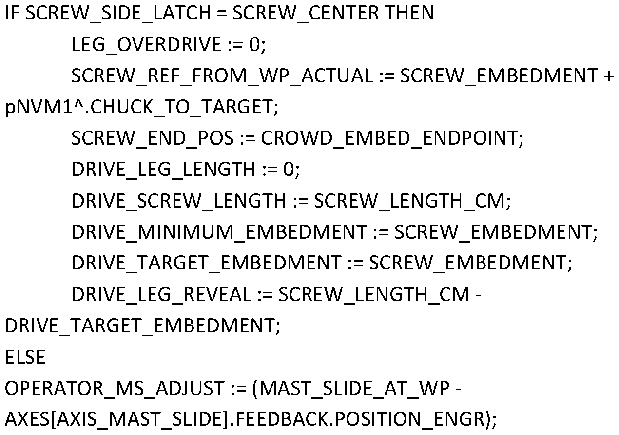
- LEG_LENGTH_ACTUAL pNVM2 A .LEG_LENGTHS_CM [INDEX];
- SCREW_END_POS LOWER_CROWD_MIN_END_POS
- FIG. 10 shows flow chart 400 detailing the steps of a method for compensating for any displacement that occurs along the drive axis during a screw anchor driving operation according to various exemplary embodiments of the invention.
- the method begins in step 405 with the screw anchor driving operation.
- the controller monitors encoder information and in step 410 determines whether the desired embedment depth has been reached. If not, driving continues. Otherwise, if the desired embedment depth has been reached, processing proceeds to step 415 where the controller determines whether or not uplift occurred while driving based on information received from one or more inclinometers or other sensors during the driving operation.
- step 425 If not, the controller will correctly assume that the actual embedment depth E was reached, and operation stops in step 425. Otherwise, if uplift was detected, operation proceeds to step 420 where the controller selects a longer upper leg length and computes an additional distance to E+ to compensate forT DA and to drive the screw anchor the additional distance as shown and discussed on the context of Figures 8A and B.
- the amount of additional distance may be based on the extent of uplift. Alternatively, the amount of distance may be the incremental distance to one of the remaining available leg lengths. If so, the machine may provide notice to the operator that upper leg length has changed so that the correct leg is pulled, and operation returns to step 405 where driving continues to E+.
- this process continues iteratively and/or if the required additional embedment depth is greater than the additional length provided by the longest available upper leg, that a custom upper leg will have to be cut from a longer length of leg material available onsite. In such cases, the machine may indicate this to the operator along with the precise leg length.
- SCREW_DRIVE_ERROR (TAN (BASE_PITCH_END - BASE_PITCH_START) *
- FIG. 11 details the steps of method 500 for performing a post-driving pull test on a driven screw anchor with the machine and mast shown in Figures 4A and 5, in accordance with various embodiments. The method begins in step 505 when the driving operation is complete but while the rotary driver is still down toward the lower end of the mast and connected to the screw anchor.
- the controller will actuate the lower crowd motor to power the drive train in the reverse direction with a fixed amount of force (e.g. 2,000 pounds) for a fixed period of time (e.g., 5 seconds). Then, in various embodiments, in step 510, the controller will monitor the position of the rotary driver and/or the carriage it is riding on relative to the mast via one or more encoders or other sensor(s) to measure any displacement along the drive axis. Next, in step 515, the controller will determine whether the measured displacement, if any, exceeds the allowable tolerances.
- a fixed amount of force e.g. 2,000 pounds
- a fixed period of time e.g. 5 seconds
- step 520 it stops so that the rotary driver may be retracted without the screw anchor so that the next one can be loaded. Otherwise, if the controller determines that the test resulted in a fail, operation may revert to step 420 of method 400 shown in Figure 10, or an substantially equivalent process where a new upper leg length is selected and a new actual embedment depth calculated so that the machine may be controlled to drive the screw anchor to the new, deeper embedment depth.
Landscapes
- Engineering & Computer Science (AREA)
- Structural Engineering (AREA)
- Life Sciences & Earth Sciences (AREA)
- General Engineering & Computer Science (AREA)
- Civil Engineering (AREA)
- Paleontology (AREA)
- Mining & Mineral Resources (AREA)
- General Life Sciences & Earth Sciences (AREA)
- Sustainable Development (AREA)
- Sustainable Energy (AREA)
- Mechanical Engineering (AREA)
- Combustion & Propulsion (AREA)
- Chemical & Material Sciences (AREA)
- Thermal Sciences (AREA)
- Physics & Mathematics (AREA)
- Earth Drilling (AREA)
- Piles And Underground Anchors (AREA)
Abstract
Description


Claims
Priority Applications (2)
| Application Number | Priority Date | Filing Date | Title |
|---|---|---|---|
| AU2020378090A AU2020378090A1 (en) | 2019-11-08 | 2020-11-06 | Systems, methods, and machines for automated screw anchor driving |
| EP20885709.4A EP4055226B1 (en) | 2019-11-08 | 2020-11-06 | Machine for automated screw anchor driving |
Applications Claiming Priority (2)
| Application Number | Priority Date | Filing Date | Title |
|---|---|---|---|
| US201962932929P | 2019-11-08 | 2019-11-08 | |
| US62/932,929 | 2019-11-08 |
Publications (1)
| Publication Number | Publication Date |
|---|---|
| WO2021092437A1 true WO2021092437A1 (en) | 2021-05-14 |
Family
ID=75847732
Family Applications (1)
| Application Number | Title | Priority Date | Filing Date |
|---|---|---|---|
| PCT/US2020/059478 Ceased WO2021092437A1 (en) | 2019-11-08 | 2020-11-06 | Systems, methods, and machines for automated screw anchor driving |
Country Status (4)
| Country | Link |
|---|---|
| US (2) | US11168456B2 (en) |
| EP (1) | EP4055226B1 (en) |
| AU (1) | AU2020378090A1 (en) |
| WO (1) | WO2021092437A1 (en) |
Families Citing this family (5)
| Publication number | Priority date | Publication date | Assignee | Title |
|---|---|---|---|---|
| EP4417895B1 (en) | 2020-09-14 | 2025-11-05 | Nextracker Inc. | Damper assembly for solar trackers |
| US20250003169A1 (en) * | 2021-10-15 | 2025-01-02 | Spinex Systems, Inc. | Piling support arrangement |
| CA3214427A1 (en) * | 2022-10-04 | 2024-04-04 | Collin WATTS | Screw pile driving apparatus |
| USD1093666S1 (en) * | 2023-02-06 | 2025-09-16 | Ojjo, Inc. | Truss cap with standard interface |
| USD1055842S1 (en) | 2023-02-09 | 2024-12-31 | Ojjo, Inc. | Truss cap with standard interface |
Citations (8)
| Publication number | Priority date | Publication date | Assignee | Title |
|---|---|---|---|---|
| US4131166A (en) * | 1974-07-26 | 1978-12-26 | Van Kooten B.V. | Pile driving device |
| JPH0711643A (en) * | 1993-06-23 | 1995-01-13 | Koken Kogyo Kk | Pile burying method and its equipment |
| US5762148A (en) * | 1995-04-01 | 1998-06-09 | Delmag Maschinenfabrik Reinhold Dornfeld Gmbh & Co. | Boring tool |
| DE202004020804U1 (en) | 2004-12-10 | 2006-03-16 | Krinner Innovation Gmbh | Foundation unit for a rod-like component comprises a sleeve open at both ends with a unit for anchoring in the ground and a unit for introducing a drive and a tool with a front operating region and an oppositely-lying region |
| EP2843138A1 (en) | 2013-08-28 | 2015-03-04 | Keller Holding GmbH | Method and device for producing ground piles |
| US9624638B2 (en) * | 2014-10-01 | 2017-04-18 | Soletanche Freyssinet | Machine and a method for making columns in ground |
| KR101773823B1 (en) | 2016-07-29 | 2017-09-01 | (주)신영기초개발 | Spin pile and construction method thereof |
| KR101811921B1 (en) * | 2015-06-02 | 2017-12-22 | 최초로 | Pile hammer |
Family Cites Families (12)
| Publication number | Priority date | Publication date | Assignee | Title |
|---|---|---|---|---|
| US2328274A (en) * | 1940-06-10 | 1943-08-31 | Lysle L Hazen | Earth drilling mechanism |
| US2334312A (en) * | 1940-08-05 | 1943-11-16 | George E Failing Supply Compan | Drilling machine |
| US2314323A (en) * | 1941-01-09 | 1943-03-23 | George E Failing Supply Compan | Rat-hole drilling attachment for rotary drilling rigs |
| US3371494A (en) * | 1966-02-04 | 1968-03-05 | Atlas Copco Ab | Method and means of anchoring an object in the ground |
| US3446295A (en) * | 1967-06-28 | 1969-05-27 | Ingersoll Rand Co | Drilling head |
| US3690109A (en) * | 1970-03-16 | 1972-09-12 | Lee A Turzillo | Method and means for producing pile or like structural columns in situ |
| US3692123A (en) * | 1970-10-27 | 1972-09-19 | Ingersoll Rand Co | Drilling machine |
| FR2807455B1 (en) * | 2000-04-11 | 2004-04-02 | Cie Du Sol | MACHINE FOR MAKING FORESTS |
| DE202004001258U1 (en) * | 2004-01-28 | 2004-04-01 | Max Streicher Gmbh & Co. Kg Aa | Device for deep drilling in geological structures |
| ES2359754T3 (en) * | 2008-06-13 | 2011-05-26 | Bauer Maschinen Gmbh | DRILLING DEVICE AND DRILLING PROCEDURE. |
| KR20140132640A (en) * | 2013-05-08 | 2014-11-18 | 주식회사 우리기초 | Auger drill with arm crushing means |
| KR101812463B1 (en) * | 2016-07-21 | 2017-12-28 | (주)도건이엔텍 | Rrotating-press type pile construction method by using tip-enlarged pile |
-
2020
- 2020-11-06 WO PCT/US2020/059478 patent/WO2021092437A1/en not_active Ceased
- 2020-11-06 AU AU2020378090A patent/AU2020378090A1/en active Pending
- 2020-11-06 US US17/091,523 patent/US11168456B2/en active Active
- 2020-11-06 EP EP20885709.4A patent/EP4055226B1/en active Active
-
2021
- 2021-10-11 US US17/498,743 patent/US12331479B2/en active Active
Patent Citations (8)
| Publication number | Priority date | Publication date | Assignee | Title |
|---|---|---|---|---|
| US4131166A (en) * | 1974-07-26 | 1978-12-26 | Van Kooten B.V. | Pile driving device |
| JPH0711643A (en) * | 1993-06-23 | 1995-01-13 | Koken Kogyo Kk | Pile burying method and its equipment |
| US5762148A (en) * | 1995-04-01 | 1998-06-09 | Delmag Maschinenfabrik Reinhold Dornfeld Gmbh & Co. | Boring tool |
| DE202004020804U1 (en) | 2004-12-10 | 2006-03-16 | Krinner Innovation Gmbh | Foundation unit for a rod-like component comprises a sleeve open at both ends with a unit for anchoring in the ground and a unit for introducing a drive and a tool with a front operating region and an oppositely-lying region |
| EP2843138A1 (en) | 2013-08-28 | 2015-03-04 | Keller Holding GmbH | Method and device for producing ground piles |
| US9624638B2 (en) * | 2014-10-01 | 2017-04-18 | Soletanche Freyssinet | Machine and a method for making columns in ground |
| KR101811921B1 (en) * | 2015-06-02 | 2017-12-22 | 최초로 | Pile hammer |
| KR101773823B1 (en) | 2016-07-29 | 2017-09-01 | (주)신영기초개발 | Spin pile and construction method thereof |
Non-Patent Citations (1)
| Title |
|---|
| See also references of EP4055226A4 |
Also Published As
| Publication number | Publication date |
|---|---|
| US20210140134A1 (en) | 2021-05-13 |
| AU2020378090A1 (en) | 2022-06-23 |
| EP4055226A1 (en) | 2022-09-14 |
| EP4055226A4 (en) | 2023-12-20 |
| US20220064893A1 (en) | 2022-03-03 |
| EP4055226B1 (en) | 2026-03-25 |
| US11168456B2 (en) | 2021-11-09 |
| US12331479B2 (en) | 2025-06-17 |
Similar Documents
| Publication | Publication Date | Title |
|---|---|---|
| US12540447B2 (en) | Systems, methods, and machines for automated screw anchor driving | |
| US12331479B2 (en) | Systems, methods, and machines for automated screw anchor driving | |
| US11542676B2 (en) | Systems, methods, and machines for autonomously driving foundation components | |
| US11828034B2 (en) | Systems, methods, and machines for improved site layout and foundation alignment | |
| US12215476B2 (en) | Systems, methods, and machines for driving multiple foundation components at once | |
| US12559899B2 (en) | Systems, methods, and machines for aligning and assembling truss foundations for single-axis trackers | |
| US7654340B2 (en) | Directional reaming system | |
| US12370640B2 (en) | Machines, systems, and methods for truss installation and assembly | |
| AU2021374402A9 (en) | Systems, methods, and machines for automated screw anchor driving | |
| US20260110151A1 (en) | Subsurface data to determine foundation installation parameter |
Legal Events
| Date | Code | Title | Description |
|---|---|---|---|
| 121 | Ep: the epo has been informed by wipo that ep was designated in this application |
Ref document number: 20885709 Country of ref document: EP Kind code of ref document: A1 |
|
| NENP | Non-entry into the national phase |
Ref country code: DE |
|
| ENP | Entry into the national phase |
Ref document number: 2020885709 Country of ref document: EP Effective date: 20220608 |
|
| ENP | Entry into the national phase |
Ref document number: 2020378090 Country of ref document: AU Date of ref document: 20201106 Kind code of ref document: A |
|
| WWG | Wipo information: grant in national office |
Ref document number: 2020885709 Country of ref document: EP |