WO2021095253A1 - レーザ切断方法及びレーザ切断装置 - Google Patents
レーザ切断方法及びレーザ切断装置 Download PDFInfo
- Publication number
- WO2021095253A1 WO2021095253A1 PCT/JP2019/044935 JP2019044935W WO2021095253A1 WO 2021095253 A1 WO2021095253 A1 WO 2021095253A1 JP 2019044935 W JP2019044935 W JP 2019044935W WO 2021095253 A1 WO2021095253 A1 WO 2021095253A1
- Authority
- WO
- WIPO (PCT)
- Prior art keywords
- laser
- cutting
- base material
- cutting line
- irradiation
- Prior art date
- Legal status (The legal status is an assumption and is not a legal conclusion. Google has not performed a legal analysis and makes no representation as to the accuracy of the status listed.)
- Ceased
Links
Images



Classifications
-
- B—PERFORMING OPERATIONS; TRANSPORTING
- B23—MACHINE TOOLS; METAL-WORKING NOT OTHERWISE PROVIDED FOR
- B23K—SOLDERING OR UNSOLDERING; WELDING; CLADDING OR PLATING BY SOLDERING OR WELDING; CUTTING BY APPLYING HEAT LOCALLY, e.g. FLAME CUTTING; WORKING BY LASER BEAM
- B23K26/00—Working by laser beam, e.g. welding, cutting or boring
- B23K26/36—Removing material
- B23K26/362—Laser etching
- B23K26/364—Laser etching for making a groove or trench, e.g. for scribing a break initiation groove
-
- B—PERFORMING OPERATIONS; TRANSPORTING
- B23—MACHINE TOOLS; METAL-WORKING NOT OTHERWISE PROVIDED FOR
- B23K—SOLDERING OR UNSOLDERING; WELDING; CLADDING OR PLATING BY SOLDERING OR WELDING; CUTTING BY APPLYING HEAT LOCALLY, e.g. FLAME CUTTING; WORKING BY LASER BEAM
- B23K26/00—Working by laser beam, e.g. welding, cutting or boring
- B23K26/36—Removing material
- B23K26/38—Removing material by boring or cutting
-
- B—PERFORMING OPERATIONS; TRANSPORTING
- B23—MACHINE TOOLS; METAL-WORKING NOT OTHERWISE PROVIDED FOR
- B23K—SOLDERING OR UNSOLDERING; WELDING; CLADDING OR PLATING BY SOLDERING OR WELDING; CUTTING BY APPLYING HEAT LOCALLY, e.g. FLAME CUTTING; WORKING BY LASER BEAM
- B23K26/00—Working by laser beam, e.g. welding, cutting or boring
- B23K26/08—Devices involving relative movement between laser beam and workpiece
- B23K26/082—Scanning systems, i.e. devices involving movement of the laser beam relative to the laser head
-
- B—PERFORMING OPERATIONS; TRANSPORTING
- B23—MACHINE TOOLS; METAL-WORKING NOT OTHERWISE PROVIDED FOR
- B23K—SOLDERING OR UNSOLDERING; WELDING; CLADDING OR PLATING BY SOLDERING OR WELDING; CUTTING BY APPLYING HEAT LOCALLY, e.g. FLAME CUTTING; WORKING BY LASER BEAM
- B23K2103/00—Materials to be soldered, welded or cut
- B23K2103/16—Composite materials
Definitions
- the present disclosure relates to a laser cutting method and a laser cutting device.
- a primary irradiation step of irradiating a cutting area of a composite material containing a reinforcing fiber as a base material with a primary laser beam capable of cutting the reinforcing fiber to perform a primary cutting process, and a primary laser beam are irradiated.
- a method for laser cutting a composite material in which a secondary irradiation step of irradiating a portion of the base material with a secondary laser beam for cutting and performing a secondary cutting process is performed see, for example, Patent Document 1).
- This laser cutting method targets a thin plate workpiece having a thickness of 2 mm.
- the primary laser beam is swiveled and moved along the longitudinal direction of the cutting area.
- the secondary laser beam is moved along the longitudinal direction of the cutting area.
- the target of laser processing is a thin plate, it was possible to properly cut the reinforcing fiber and the resin in the composite material by the above two steps.
- the target is a thick plate
- the irradiation time becomes longer and the cutting depth becomes deeper due to laser irradiation.
- the heat input spreads in the width direction, and the shape and quality of the cut surface deteriorate.
- the cutting of the reinforcing fibers by the primary irradiation step and the cutting of the base material by the secondary irradiation step are performed separately, the processing time for cutting the composite material becomes long.
- the laser cutting method of the present disclosure is a laser cutting method of irradiating the surface of a base material made of a composite material with a laser to cut the base material, wherein the laser cutting method is performed along the length direction of a cutting line for cutting the base material.
- the irradiation step of irradiating the cutting line by oscillating the laser in the intersecting direction intersecting the length direction of the cutting line while moving the laser relative to the base material is repeatedly executed on the cutting line.
- the base material is cut, and in the irradiation step, the sway width of the laser in the crossing direction is reduced as the depth in the depth direction from the front surface to the back surface of the base material becomes deeper.
- the laser cutting device of the present disclosure is a laser cutting device that irradiates the surface of a base material made of a composite material with a laser to cut the base material, and is a laser irradiation unit that irradiates the laser toward the base material.
- a laser scanner that scans the laser on the base material, and a moving portion that moves the laser relative to the base material along the length direction of the cutting line that cuts the base material.
- a control unit that controls the operation of the laser irradiation unit, the laser scanner, and the moving unit is provided, and the control unit makes the laser relative to the base material along the length direction of the cutting line.
- the base metal is cut by repeatedly executing the irradiation step of irradiating the cutting line by oscillating the laser in the crossing direction intersecting the length direction of the cutting line while moving the laser.
- the sway width of the laser in the crossing direction is reduced as the depth in the depth direction from the front surface to the back surface of the base metal becomes deeper.
- FIG. 1 is a diagram schematically showing a laser cutting device according to the first embodiment.
- FIG. 2 is a top view of the oscillating laser.
- FIG. 3 is a diagram illustrating the trajectory of the oscillating laser.
- FIG. 4 is an explanatory diagram of the laser cutting method according to the first embodiment.
- FIG. 5 is an explanatory diagram of the laser cutting method according to the second embodiment.
- FIG. 6 is an explanatory diagram of a laser cutting method according to a modified example of the second embodiment.
- FIG. 1 is a diagram schematically showing a laser cutting device according to the first embodiment.
- the laser cutting device 10 according to the first embodiment is a device capable of cutting the composite material 5 by irradiating the composite material 5 as a base material with a laser L.
- the composite material 5 contains a reinforcing fiber and a resin.
- CFRP carbon fiber reinforced plastic
- GFRP glass fiber reinforced plastic
- CFRPT carbon fiber reinforced plastic
- GMT Fiber reinforced plastics such as glass long fiber reinforced plastics
- Cu-mesh copper mesh
- the laser cutting device 10 includes a support base 6, a laser irradiation device (laser irradiation unit) 11, a scanning optical system (laser scanner) 12, a condensing optical system 13, and a moving unit 14. , A control unit 15, and a gas nozzle.
- the support base 6 supports the composite material 5 at a predetermined position.
- the support base 6 may be a moving stage for moving the composite material 5 in a horizontal plane.
- the laser L irradiated from the laser irradiation device 11 is irradiated substantially perpendicular to the surface of the composite material 5 arranged on the support base 6.
- the laser irradiation device 11 is a device that outputs a laser L.
- the laser irradiation device 11 may be a pulse wave (Continuous Wave) or a continuous wave (CW) as the laser L to be output.
- CW continuous wave
- the laser irradiation device 11 may irradiate the laser L in a single mode or a multi-mode.
- the scanning optical system 12 is an optical system that scans the laser L irradiated from the laser irradiation device 11 on the composite material 5.
- the scanning optical system 12 includes a scanner capable of operating a laser within the surface of the composite material 5, and as the scanner, for example, a galvano mirror is used.
- a galvano mirror is used as the scanner used in the embodiment.
- a prism rotator, a chip tilt mirror, or the like can be used in addition to the galvano mirror.
- the condensing optical system 13 is an optical system that condenses the laser L emitted from the scanning optical system 12 at the focal point and irradiates the composite material 5 with the focused laser L.
- the condensing optical system 13 includes an optical member such as a condensing lens.
- the moving unit 14 is a moving mechanism that moves the laser L with respect to the composite material 5.
- the moving unit 14 integrally moves the scanning optical system 12 and the condensing optical system 13.
- the moving unit 14 moves the laser L along the cutting line I that cuts the composite material 5.
- the gas nozzle supplies the assist gas G to the irradiation position of the laser L irradiated from the laser irradiation device 11.
- the assist gas G a rare gas such as nitrogen or argon, or air is applied.
- the control unit 15 is connected to each unit including the laser irradiation device 11, the scanning optical system 12, the condensing optical system 13, and the moving unit 14, and controls the operation of the laser cutting device 10 by controlling each unit.
- the control unit 15 adjusts the irradiation conditions of the laser L irradiated from the laser irradiation device 11 by controlling the laser irradiation device 11, for example. Further, the control unit 15 controls the scanning operation of the laser L on the surface of the composite material 5 by controlling the scanning optical system 12. Further, the control unit 15 adjusts the focal position of the laser L by controlling the condensing optical system 13. Further, the control unit 15 controls the movement of the laser L with respect to the composite material 5 by controlling the moving unit 14.
- the laser cutting device 10 configured as described above irradiates the laser L from the laser irradiation device 11 and guides the irradiated laser L to the scanning optical system 12.
- the laser cutting device 10 changes the irradiation position of the laser L on the surface of the composite material 5 by scanning the laser L incident on the scanning optical system 12.
- the laser cutting device 10 causes the laser L emitted from the scanning optical system 12 to enter the focusing optical system 13 and irradiates the composite material 5 with the focused laser L.
- the laser cutting device 10 controls the moving unit 14 to move the laser L along the cutting line I.
- FIG. 2 is a top view of the oscillating laser.
- FIG. 3 is a diagram illustrating the trajectory of the oscillating laser.
- FIG. 4 is an explanatory diagram of the laser cutting method according to the first embodiment.
- the thickness of the composite material 5 in the thickness direction in which the front surface and the back surface face each other is thicker than 2 mm, and the thicker the plate thickness (up to 100 mm), the more effective the cutting according to the embodiment. Becomes large.
- the plate thickness is particularly preferably 4 mm or more, and more preferably 10 mm or more.
- the composite material 5 is cut while the laser L is oscillating.
- the laser L is oscillating at least in the width direction (intersection direction) intersecting the length direction of the cutting line I. That is, the laser L may be a scan that oscillates along the length direction and the width direction of the cutting line I, or may be a scan that oscillates along the width direction of the cutting line I.
- the laser L draws a predetermined trajectory R with respect to the surface of the composite material 5.
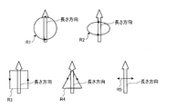
- a scan that draws an orbital locus R1 that orbits in a circular shape on the surface of the composite material 5 and orbits in an elliptical shape there are a scan for drawing an orbital locus R2, a scan for drawing an orbital locus R3 orbiting in a rectangular shape, and a scanning for drawing an orbital locus R4 orbiting in a triangular shape.
- a scan that sways along the width direction of the cutting line I for example, there is a scan that draws a linear swaying locus R5 on the surface of the composite material 5.
- each locus R1 to R5 shown in FIG. 3 in the width direction is substantially the same as the length of the cutting line I in the width direction.
- the laser cutting device 10 cuts the composite material 5 by moving the laser L that draws the trajectories R1 to R5 shown in FIG. 3 along the cutting line I.
- the scanning speed in the orbital trajectories R1 to R4 is higher than the scanning speed in the length direction of the cutting line I.
- the irradiation conditions of the laser L that is, the cutting conditions for cutting the composite material 5 are as follows.
- the laser output of the laser L irradiated from the laser irradiation device 11 is a high-power laser having a laser output of more than 0.2 kW and 500 kW or less.
- the wavelength of the laser L for example, a wavelength in the 1 ⁇ m band, a wavelength in which green is visible light, a wavelength in which blue is visible light, and a wavelength in which ultraviolet light is applicable can be applied.
- the frequency of swing in the width direction of the laser L is in the range of 10 Hz to 10,000 Hz.
- the moving speed of the cutting line I in the length direction is preferably in the range of 1 to 1000 m / min.
- the scanning speed of the laser L in the above-mentioned orbital trajectories R1 to R4 is faster than the scanning speed in the length direction of the cutting line I.
- the scanning speed in the orbital trajectories R1 to R4 of the laser L is faster than 1 m / min, and more preferably 100 m / min or more.
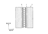
- FIG. 4 describes a case where the scanning of the laser L is a scanning for drawing an orbital locus R1 orbiting in the circular shape of FIG.
- the vertical direction of FIG. 4 is the thickness direction of the composite material 5.
- the width direction of the cutting line I is the left-right direction in FIG. 4, and the length direction is the depth direction in FIG. Further, the cutting line I is preset with respect to the composite material 5, and the laser L is moved along the length direction of the preset cutting line I.
- the composite material 5 is cut by repeatedly executing the irradiation step S1 of irradiating the cutting line I with the laser L on the cutting line I.
- the laser L moves along the length direction of the cutting line I while scanning to draw the orbital locus R1 by swinging in the width direction and the length direction of the cutting line I.
- One layer of the composite material 5 is removed by moving the cutting line I in the longitudinal direction.
- the swaying width in the width direction of the laser L is reduced as the depth in the depth direction from the front surface to the back surface of the composite material 5 becomes deeper. That is, the sway width in the width direction of the laser L in the next irradiation step S1 is smaller than the sway width in the width direction of the laser L in the current irradiation step S1.
- the irradiation step S1 is repeatedly executed with the center T in the width direction of the swing width of the laser L and the center in the width direction of the cutting line I aligned.
- the removal amount of the composite material 5 may be the same removal amount.
- the focal point O of the laser L in the current irradiation step S1 is aligned with the formation surface formed in the previous irradiation step S1 to irradiate the laser L. That is, the position of the focal point O of the laser L in the current irradiation step S1 is deeper in the depth direction than the position of the focal point O of the laser L in the previous irradiation step S1.
- the irradiation conditions of the laser L in the irradiation step S1 performed a plurality of times are the same irradiation conditions.
- the cut groove formed by removing the composite material 5 by repeatedly executing the irradiation step S1 has the shape shown in FIG. That is, in the cross section cut along the plane orthogonal to the length direction of the cutting line I, the cutting groove has a tapered shape that tapers from the front surface to the back surface of the composite material 5.
- the irradiation step S1 in which the laser L is swung in the width direction to irradiate the cutting line I can be repeatedly executed. Therefore, since it is not necessary to divide the irradiation step S1 into a plurality of irradiation steps using different lasers L, the cutting process of the composite material 5 can be efficiently executed. Further, since the composite material 5 for one layer can be removed by the one-pass laser L, the efficiency of the cutting process in the irradiation step S1 can be improved. Further, since the laser cutting method can be executed by using the single laser irradiation device 11, the device configuration of the laser cutting device 10 can be simplified.
- the laser L can be applied to the composite material 5 so as to draw the orbital trajectories R1 to R4 on the composite material 5. Therefore, the composite material 5 for one layer in the cutting line I can be removed while suppressing the occurrence of the composite material 5 left behind.
- the composite material can be selected by selecting the shapes of the orbital loci R1 to R4 according to the mode of laser cutting.
- the cutting of 5 can be preferably performed.
- the irradiation step S1 can be repeatedly executed with the center T in the width direction of the swing width of the laser L and the center in the width direction of the cutting line I aligned. Therefore, the irradiation step S1 can be repeatedly executed without changing the center T of the swing width of the laser L to cut the composite material 5.
- the reinforcing fibers and the resin contained in the composite material 5 are appropriately cut. Can be done.
- the composite material 5 which is a thick plate thicker than 2 mm can be appropriately cut.
- the irradiation conditions of the laser L in the irradiation step S1 performed a plurality of times are the same conditions, but the irradiation conditions may be changed for each irradiation step S1. That is, even if the irradiation conditions such as the laser output of the laser L, the wavelength of the laser L, the frequency of the swing in the width direction of the laser L, and the cutting speed in the length direction of the cutting line I are changed for each irradiation step S1. Good.
- FIG. 5 is an explanatory diagram of the laser cutting method according to the second embodiment.
- the irradiation step is performed in a state where one end of the laser L in the width direction of the swing width (left side in FIG. 5) and one end of the cutting line I in the width direction are combined.
- S11 is repeatedly executed. That is, in the current irradiation step S11, the center T of the swaying width of the laser L is set to the swaying width of the laser L as compared with the previous irradiation step S11 so that one end side of the swaying width of the laser L becomes a reference. It is moved to one end side.
- the cutting groove formed by removing the composite material 5 has the shape shown in FIG. That is, in the cross section cut by the plane orthogonal to the length direction of the cutting line I, the cutting groove is a vertical plane in which the cutting surface at one end of the swing width of the laser L is along the thickness direction of the composite material 5. On the other hand, the cut surface at the other end of the swing width of the laser L becomes an inclined surface that is inclined with respect to the thickness direction.
- the irradiation step S11 is repeatedly executed with one end in the swing width of the laser L and one end in the width direction of the cutting line I aligned. Can be done. Therefore, since the end surface of the cut composite material 5 can be a vertical surface, it is possible to perform cutting processing with high accuracy.
- the composite material 5 that becomes the vertical surface after cutting can be used as a product, and the composite material 5 that becomes the inclined surface after cutting can be used as the balance.
- FIG. 6 is an explanatory diagram of a laser cutting method according to a modified example of the second embodiment.
- the laser L is tilted relative to the composite material 5.
- the laser L is inclined with respect to the thickness direction of the composite material 5 in the cross section of FIG. 6 orthogonal to the length direction of the cutting line I.
- the outside of the laser L before being focused on the focal point O is in the thickness direction of the composite material 5. Tilt to imitate. Therefore, in the cutting groove, the cutting surface at one end of the swing width of the laser L can be a highly accurate vertical surface along the thickness direction of the composite material 5.
- the cutting surface after the tip is formed at one end of the cutting line I.
- the vertical surface with high accuracy along the thickness direction of the composite material 5 can be obtained.
- the laser cutting method and the laser cutting device 10 described in each embodiment are grasped as follows, for example.
- the laser cutting method is a laser cutting method for cutting the base material (composite material 5) by irradiating the surface of the base material made of the composite material 5 with a laser L to cut the base material. While moving the laser L relative to the base material along the length direction of the line I, the laser L is moved in the intersecting direction (width direction) intersecting the length direction of the cutting line I.
- the base metal is cut by repeatedly executing the irradiation steps S1, S11, and S21 for oscillating and irradiating the cutting line I. In the irradiation steps S1, S11, and S21, the laser L The sway width in the width direction is reduced as the depth in the depth direction from the front surface to the back surface of the base metal becomes deeper.
- the irradiation step S1 in which the laser L is swung in the width direction to irradiate the cutting line I can be repeatedly executed. Therefore, since it is not necessary to divide the irradiation step S1 into a plurality of irradiation steps using different lasers L, the cutting process of the base material (composite material 5) can be efficiently executed. Further, since the composite material 5 for one layer can be removed by the one-pass laser L, the efficiency of the cutting process in the irradiation step S1 can be improved. Further, since the laser cutting method can be executed by using the single laser irradiation device 11, the device configuration of the laser cutting device 10 can be simplified.
- the laser L is swung in the crossing direction (width direction) and the length direction of the cutting line I, thereby causing the mother.
- the base material is irradiated with the laser L so as to draw orbital loci R1 to R4 around which the laser L orbits on the material.
- the laser L can be applied to the composite material 5 so as to draw the orbital trajectories R1 to R4 on the base material (composite material 5). Therefore, the composite material 5 for one layer in the cutting line I can be removed while suppressing the occurrence of the composite material 5 left behind.
- the scanning speed in the orbital loci R1 to R4 is faster than the scanning speed in the length direction of the cutting line I.
- the scanning speed of the laser L in the orbital trajectories R1 to R4 can be increased, so that heat input to the base material (composite material 5) can be suppressed.
- the orbital loci R1 to R4 have a circular shape, an elliptical shape, a fan shape, a rectangular shape, a triangular shape, or a polygonal shape. It is a combined shape.
- the shapes of the orbital loci R1 to R4 can be various, so that the composite material 5 can be cut by selecting the shapes of the orbital loci R1 to R4 according to the mode of laser cutting. Can be preferably performed.
- the irradiation step S1 is repeated in a state where the center T of the laser L in the width direction of the swing width and the center of the cutting line I in the width direction are aligned. Will be executed.
- the irradiation step S1 can be repeatedly executed with the center T in the width direction of the swing width of the laser L and the center in the width direction of the cutting line I aligned. Therefore, the irradiation step S1 can be repeatedly executed without changing the center T of the swing width of the laser L to cut the composite material 5.
- the irradiation steps S11 and S21 include one end of the laser L in the width direction of the swing width and one end of the cutting line I in the width direction. It is executed repeatedly with the above.
- the irradiation step S11 can be repeatedly executed with one end in the swing width of the laser L and one end in the width direction of the cutting line I aligned. Therefore, since the end surface of the cut composite material 5 can be a vertical surface, it is possible to perform cutting processing with high accuracy.
- the laser is a high-power laser having a laser output of more than 0.2 kW and 500 kW or less.
- the reinforcing fibers and the resin contained in the composite material 5 can be appropriately cut.
- the thickness of the base metal is thicker than 2 mm.
- a base material which is a plate thicker than 2 mm, particularly a plate having a thickness of 4 mm or more, and further 10 mm or more.
- the laser cutting device 10 is the laser cutting device 10 that irradiates the surface of the base material made of the composite material with the laser L to cut the base material (composite material 5) toward the base material.
- a moving unit 14 that moves the laser L relative to the base material along the longitudinal direction, and a control unit 15 that controls the operations of the laser irradiation unit, the laser scanner, and the moving unit 14.
- the control unit 15 moves the laser L relative to the base material along the length direction of the cutting line I, while moving the laser L in the length direction of the cutting line I.
- the base metal is cut by repeatedly executing the irradiation steps S1, S11, and S21 for irradiating the laser in the intersecting direction (width direction) intersecting with the cutting line I, and the irradiation step S1 , S11, S21, the sway width of the laser L in the width direction is reduced as the depth in the depth direction from the front surface to the back surface of the base metal becomes deeper.
- the irradiation step S1 in which the laser L is swung in the width direction to irradiate the cutting line I can be repeatedly executed. Therefore, since it is not necessary to divide the irradiation step S1 into a plurality of irradiation steps using different lasers L, the cutting process of the base material (composite material 5) can be efficiently executed. Further, since the composite material 5 for one layer can be removed by the one-pass laser L, the efficiency of the cutting process in the irradiation step S1 can be improved. Further, since the laser cutting method can be executed by using the single laser irradiation device 11, the device configuration of the laser cutting device 10 can be simplified.
- the laser cutting device 10 further includes a gas nozzle that supplies assist gas toward the irradiation position of the laser L that is irradiated from the laser irradiation unit (laser irradiation device 11).
- the gas nozzle may be coaxial with the laser or may have a separate axis.
- the assist gas can be supplied toward the irradiation position of the laser L, it is possible to suppress the heat input to the base material (composite material 5) due to the laser irradiation.
Landscapes
- Physics & Mathematics (AREA)
- Optics & Photonics (AREA)
- Engineering & Computer Science (AREA)
- Plasma & Fusion (AREA)
- Mechanical Engineering (AREA)
- Laser Beam Processing (AREA)
Abstract
複合材からなる母材の表面にレーザを照射して母材を切断するレーザ切断方法及びレーザ切断装置において、母材を切断する切断ラインの長さ方向に沿って、レーザを母材に対して相対的に移動させながら、レーザを切断ラインの長さ方向に交差する公差方向に搖動させて照射する照射ステップを、切断ラインに対して繰り返し実行することにより、母材を切断しており、照射ステップでは、レーザの幅方向における搖動幅を、母材の表面から裏面に向かう深さ方向における深さが深くなるにつれて小さくする。
Description
本開示は、レーザ切断方法及びレーザ切断装置に関するものである。
従来、レーザ切断方法として、強化繊維を母材に含む複合材の裁断エリアに、強化繊維を裁断可能な一次レーザビームを照射して一次裁断加工を施す一次照射ステップと、一次レーザビームが照射された部位に母材を切断加工な二次レーザビームを照射して二次裁断加工を施す二次照射ステップとを行う複合材のレーザ切断方法が知られている(例えば、特許文献1参照)。このレーザ切断方法では、2mm厚となる薄板のワークを対象としている。一次照射ステップでは、一次レーザビームを旋回させながら、裁断エリアの長手方向に沿って移動させている。二次照射ステップでは、二次レーザビームを裁断エリアの長手方向に沿って移動させている。このようなレーザ切断方法は、複合材中の強化繊維と樹脂とに対して適正な切断を行うための方法となっており、2mm厚となる薄板のワークでは、上記の2つのステップで複合材を切断することが可能となっている。
ところで、特許文献1のレーザ切断方法では、レーザ加工の対象が薄板であるため、上記の2つのステップで複合材中の強化繊維と樹脂とを適正に切断が可能であったが、レーザ加工の対象が厚板である場合、厚板となる複合材に対して同様の一次照射ステップ及び二次照射ステップで加工を行おうとすると、照射時間が長くなり切断深さが深くなる位置ほどレーザ照射による入熱が幅方向に広がり切断面の形状や品質が悪化する。また、一次照射ステップによる強化繊維の裁断と、二次照射ステップによる母材の裁断とを分けて実行するため、複合材の切断加工の加工時間が長くなってしまう。
そこで、本開示は、複合材の切断加工の効率化を図ることができるレーザ切断方法及びレーザ切断装置を提供することを課題とする。
本開示のレーザ切断方法は、複合材からなる母材の表面にレーザを照射して前記母材を切断するレーザ切断方法において、前記母材を切断する切断ラインの長さ方向に沿って、前記レーザを前記母材に対して相対的に移動させながら、前記レーザを前記切断ラインの前記長さ方向に交差する交差方向に搖動させて照射する照射ステップを、前記切断ラインに対して繰り返し実行することにより、前記母材を切断しており、前記照射ステップでは、前記レーザの前記交差方向における搖動幅を、前記母材の表面から裏面に向かう深さ方向における深さが深くなるにつれて小さくする。
また、本開示のレーザ切断装置は、複合材からなる母材の表面にレーザを照射して前記母材を切断するレーザ切断装置において、前記母材へ向かって、前記レーザを照射するレーザ照射部と、前記母材上において前記レーザを走査させるレーザスキャナと、前記母材を切断する切断ラインの長さ方向に沿って、前記レーザを前記母材に対して相対的に移動させる移動部と、前記レーザ照射部、前記レーザスキャナ及び前記移動部の動作を制御する制御部と、を備え、前記制御部は、前記切断ラインの長さ方向に沿って、前記レーザを前記母材に対して相対的に移動させながら、前記レーザを前記切断ラインの前記長さ方向に交差する交差方向に搖動させて照射する照射ステップを、前記切断ラインに対して繰り返し実行することで、前記母材を切断しており、前記照射ステップにおいて、前記レーザの前記交差方向における搖動幅を、前記母材の表面から裏面に向かう深さ方向における深さが深くなるにつれて小さくする。
本開示によれば、複合材の切断加工の効率化を図ることができる。
以下に、本開示に係る実施形態を図面に基づいて詳細に説明する。なお、この実施形態によりこの発明が限定されるものではない。また、下記実施形態における構成要素には、当業者が置換可能かつ容易なもの、あるいは実質的に同一のものが含まれる。さらに、以下に記載した構成要素は適宜組み合わせることが可能であり、また、実施形態が複数ある場合には、各実施形態を組み合わせることも可能である。
[実施形態1]
図1は、実施形態1に係るレーザ切断装置を模式的に示す図である。図1に示すように、実施形態1に係るレーザ切断装置10は、母材となる複合材5にレーザLを照射して、複合材5を切断することが可能な装置となっている。
図1は、実施形態1に係るレーザ切断装置を模式的に示す図である。図1に示すように、実施形態1に係るレーザ切断装置10は、母材となる複合材5にレーザLを照射して、複合材5を切断することが可能な装置となっている。
(複合材)
複合材5としては、強化繊維及び樹脂を含むものとなっており、例えば、CFRP(炭素繊維強化熱硬化性プラスチック)、GFRP(ガラス繊維強化プラスチック)、CFRPT(炭素繊維強化熱可塑性プラスチック)GMT(ガラス長繊維強化プラスチック)、Cu-mesh(銅メッシュ)等の繊維強化プラスチックである。
複合材5としては、強化繊維及び樹脂を含むものとなっており、例えば、CFRP(炭素繊維強化熱硬化性プラスチック)、GFRP(ガラス繊維強化プラスチック)、CFRPT(炭素繊維強化熱可塑性プラスチック)GMT(ガラス長繊維強化プラスチック)、Cu-mesh(銅メッシュ)等の繊維強化プラスチックである。
(レーザ切断装置)
図1に示すように、レーザ切断装置10は、支持台6と、レーザ照射装置(レーザ照射部)11と、走査光学系(レーザスキャナ)12と、集光光学系13と、移動部14と、制御部15と、ガスノズルとを含んで構成される。
図1に示すように、レーザ切断装置10は、支持台6と、レーザ照射装置(レーザ照射部)11と、走査光学系(レーザスキャナ)12と、集光光学系13と、移動部14と、制御部15と、ガスノズルとを含んで構成される。
支持台6は、複合材5を所定位置に支持する。なお、支持台6は、複合材5を水平面内において移動させる移動ステージとしてもよい。レーザ照射装置11から照射されるレーザLは、支持台6に配置された複合材5の表面に対して、ほぼ垂直に照射される。
レーザ照射装置11は、レーザLを出力する装置である。レーザ照射装置11は、出力するレーザLとして、パルス波(Continuous Wave)または連続波(CW)であってもよい。実施形態1では、エネルギーを連続して供給可能な連続波となるレーザLを照射するレーザ照射装置11を用いることが好ましい。また、レーザ照射装置11は、シングルモードまたはマルチモードでレーザLを照射してもよい。実施形態1では、集光性の高いシングルモードでレーザLを照射するレーザ照射装置11を用いることが好ましい。
走査光学系12は、レーザ照射装置11から照射されたレーザLを、複合材5上において走査させる光学系である。走査光学系12は、複合材5の表面内においてレーザを操作可能なスキャナを含み、スキャナとしては、例えば、ガルバノミラーが用いられる。なお、実施形態で使用するスキャナとしては、ガルバノミラー以外に、プリズムローテータまたはチップチルト鏡等も使用可能である。
集光光学系13は、走査光学系12から出射されたレーザLを焦点において集光し、集光したレーザLを複合材5に照射する光学系である。集光光学系13は、集光レンズ等の光学部材を含んで構成されている。
移動部14は、レーザLを複合材5に対して移動させる移動機構である。移動部14は、例えば、走査光学系12及び集光光学系13を一体に移動させている。移動部14は、複合材5を切断する切断ラインIに沿ってレーザLを移動させている。
ガスノズルは、レーザ照射装置11から照射されたレーザLの照射位置に、アシストガスGを供給する。アシストガスGとしては、窒素やアルゴンなどの希ガス、または空気が適用される。
制御部15は、レーザ照射装置11、走査光学系12、集光光学系13及び移動部14を含む各部に接続され、各部を制御することで、レーザ切断装置10の動作を制御している。制御部15は、例えば、レーザ照射装置11を制御することで、レーザ照射装置11から照射されるレーザLの照射条件を調整する。また、制御部15は、走査光学系12を制御することで、複合材5の表面上におけるレーザLの走査動作を制御している。さらに、制御部15は、集光光学系13を制御することで、レーザLの焦点位置を調整している。また、制御部15は、移動部14を制御することで、複合材5に対するレーザLの移動を制御している。
上記のように構成されるレーザ切断装置10は、レーザ照射装置11からレーザLを照射させ、照射されたレーザLを、走査光学系12に案内する。レーザ切断装置10は、走査光学系12に入射したレーザLを走査させることで、複合材5の表面上におけるレーザLの照射位置を可変させる。レーザ切断装置10は、走査光学系12から出射したレーザLを、集光光学系13に入射させ、集光したレーザLを複合材5に照射する。レーザ切断装置10は、移動部14を制御して、レーザLを切断ラインIに沿って移動させる。
(レーザ切断方法)
次に、図2から図4を参照して、上記のレーザ切断装置10を用いて、複合材5を切断するレーザ切断方法について説明する。図2は、揺動するレーザを上面から見た図である。図3は、揺動するレーザの軌跡を例示した図である。図4は、実施形態1に係るレーザ切断方法に関する説明図である。ここで、複合材5は、例えば、表面と裏面とが対向する厚さ方向における厚みが、2mmより厚い板厚となっており、板厚が厚い(~100mm)ほど、実施形態による切断の効果は大となる。板厚は、特に4mm以上で好適であり、さらに好適には、10mm以上である。
次に、図2から図4を参照して、上記のレーザ切断装置10を用いて、複合材5を切断するレーザ切断方法について説明する。図2は、揺動するレーザを上面から見た図である。図3は、揺動するレーザの軌跡を例示した図である。図4は、実施形態1に係るレーザ切断方法に関する説明図である。ここで、複合材5は、例えば、表面と裏面とが対向する厚さ方向における厚みが、2mmより厚い板厚となっており、板厚が厚い(~100mm)ほど、実施形態による切断の効果は大となる。板厚は、特に4mm以上で好適であり、さらに好適には、10mm以上である。
実施形態1のレーザ切断方法では、レーザLを搖動させながら、複合材5の切断を行っている。レーザLは、少なくとも切断ラインIの長さ方向に交差する幅方向(交差方向)に搖動している。つまり、レーザLは、切断ラインIの長さ方向及び幅方向に沿って搖動する走査であってもよいし、切断ラインIの幅方向に沿って搖動する走査であってもよい。レーザLを搖動して走査させることにより、複合材5の表面に対して、レーザLは所定の軌跡Rを描く。
図3に示すように、切断ラインIの長さ方向及び幅方向に搖動する走査としては、例えば、複合材5の表面上において、円形状に周回する周回軌跡R1を描く走査、楕円形状に周回する周回軌跡R2を描く走査、矩形形状に周回する周回軌跡R3を描く走査、三角形状に周回する周回軌跡R4を描く走査がある。また、切断ラインIの幅方向に沿って搖動する走査としては、例えば、複合材5の表面上において、直線状に搖動する軌跡R5を描く走査がある。それ以外に扇形形状や多角形状、上記を組み合わせた形状が適用可能である。図3に示す各軌跡R1~R5の幅方向における揺動幅は、切断ラインIの幅方向における長さと、ほぼ同じ長さとなっている。そして、レーザ切断装置10は、図3に示す軌跡R1~R5を描くレーザLを切断ラインIに沿って移動させることで、複合材5を切断している。なお、レーザLは、上記の周回軌跡R1~R4における走査速度が、切断ラインIの長さ方向における走査速度に比して速くなっている。
また、実施形態1のレーザ切断方法では、レーザLの照射条件、すなわち、複合材5を切断する切断条件を、下記のとおりとしている。レーザ照射装置11から照射されるレーザLのレーザ出力は、0.2kWよりも大きく、500kW以下となる高出力レーザとしている。また、レーザLの波長は、例えば、1μm帯となる波長、グリーンの可視光となる波長、ブルーの可視光となる波長、紫外光となる波長が適用可能である。レーザLの幅方向における揺動の周波数は、10Hz~10,000Hzの範囲としている。切断ラインIの長さ方向における移動速度、つまり、切断速度は、1~1000m/minの範囲が適する。また、レーザLは、上記の周回軌跡R1~R4における走査速度が、切断ラインIの長さ方向における走査速度に比して速いことが望ましい。好適には、レーザLの周回軌跡R1~R4における走査速度は、1m/minより速く、より好適には、100m/min以上である。
図4を参照して、複合材5を切断するレーザ切断方法について説明する。なお、図4では、レーザLの走査が、図3の円形状に周回する周回軌跡R1を描く走査である場合について説明する。複合材5は、図4の上下方向が、厚さ方向となっている。切断ラインIは、幅方向が、図4の左右方向となっており、長さ方向が、図4の奥行き方向となっている。また、切断ラインIは、複合材5に対して予め設定されており、予め設定された切断ラインIの長さ方向に沿って、レーザLを移動させている。
レーザ切断方法では、切断ラインIに対して、レーザLを照射する照射ステップS1を、切断ラインIに対して繰り返し実行することにより、複合材5を切断している。照射ステップS1では、レーザLが、切断ラインIの幅方向及び長さ方向に搖動して周回軌跡R1を描く走査を行いながら、切断ラインIの長さ方向に沿って移動している。切断ラインIの長手方向における移動により、1層分の複合材5の除去を行っている。
また、繰り返し行われる照射ステップS1では、レーザLの幅方向における搖動幅を、複合材5の表面から裏面に向かう深さ方向における深さが深くなるにつれて小さくしている。つまり、次回の照射ステップS1におけるレーザLの幅方向における搖動幅は、今回の照射ステップS1におけるレーザLの幅方向における搖動幅よりも小さくなっている。このとき、照射ステップS1は、レーザLの搖動幅の幅方向における中心Tと、切断ラインIの幅方向の中心とを合わせた状態で、繰り返し実行される。なお、次回の照射ステップS1においてレーザLを照射することにより除去される1層分の複合材5の除去量と、今回の照射ステップS1においてレーザLを照射することにより除去される1層分の複合材5の除去量とは、同じ除去量としてもよい。
また、照射ステップS1では、今回の照射ステップS1におけるレーザLの焦点Oを、前回の照射ステップS1において形成された形成面に合わせて、レーザLを照射している。つまり、今回の照射ステップS1におけるレーザLの焦点Oの位置は、前回の照射ステップS1におけるレーザLの焦点Oの位置に比べて、深さ方向において深い位置となっている。なお、複数回行われる照射ステップS1のレーザLの照射条件は、同じ照射条件となっている。
照射ステップS1を繰り返し実行することで、複合材5が除去されることにより形成される切断溝は、図4に示す形状となる。つまり、切断ラインIの長さ方向に直交する面で切った断面において、切断溝は、複合材5の表面から裏面に向かって先細りとなるテーパ形状となっている。
以上のように、実施形態1によれば、切断ラインIに対して、レーザLを幅方向に搖動させて照射する照射ステップS1を繰り返し実行することができる。このため、照射ステップS1を、異なるレーザLを用いた複数の照射ステップに分ける必要がないため、複合材5の切断加工を効率よく実行することができる。また、1層分の複合材5の除去を、ワンパスのレーザLで行うことができるため、照射ステップS1における切断加工の効率化も図ることができる。さらに、単一のレーザ照射装置11を用いて、レーザ切断方法を実行することができるため、レーザ切断装置10の装置構成を簡易なものとすることができる。
また、実施形態1によれば、複合材5上において周回軌跡R1~R4を描くように、レーザLを複合材5に照射することができる。このため、切断ラインIにおける1層分の複合材5を、複合材5の取り残しの発生を抑制しつつ、除去することができる。
また、実施形態1によれば、周回軌跡R1~R4の形状について、様々な形状とすることができるため、レーザ切断の様態に応じた周回軌跡R1~R4の形状を選定することにより、複合材5の切断を好適に行うことができる。
また、実施形態1によれば、レーザLの搖動幅の幅方向における中心Tと、切断ラインIの幅方向の中心とを合わせた状態で、照射ステップS1を繰り返し実行することができる。このため、レーザLの搖動幅の中心Tを変更することなく、照射ステップS1を繰り返し実行して、複合材5の切断を行うことができる。
また、実施形態1によれば、レーザ出力が0.2kWよりも大きく、500kW以下となる高出力レーザを用いることができるため、複合材5に含まれる強化繊維及び樹脂を、適切に切断することができる。
また、実施形態1によれば、2mmよりも厚い厚板となる複合材5を適切に切断することができる。
なお、実施形態1では、複数回行われる照射ステップS1のレーザLの照射条件を同じ条件としたが、照射ステップS1毎に照射条件を変更してもよい。つまり、照射条件である、レーザLのレーザ出力、レーザLの波長、レーザLの幅方向における揺動の周波数、切断ラインIの長さ方向における切断速度を、照射ステップS1毎に変更してもよい。
[実施形態2]
次に、図5を参照して、実施形態2に係るレーザ切断装置及びレーザ切断方法について説明する。なお、実施形態2では、重複した記載を避けるべく、実施形態1と異なる部分について説明し、実施形態1と同様の構成である部分については、同じ符号を付して説明する。図5は、実施形態2に係るレーザ切断方法に関する説明図である。
次に、図5を参照して、実施形態2に係るレーザ切断装置及びレーザ切断方法について説明する。なお、実施形態2では、重複した記載を避けるべく、実施形態1と異なる部分について説明し、実施形態1と同様の構成である部分については、同じ符号を付して説明する。図5は、実施形態2に係るレーザ切断方法に関する説明図である。
実施形態2のレーザ切断方法では、レーザLの搖動幅の幅方向における一方(図5の左側)の端部と、切断ラインIの幅方向における一方の端部とを合わせた状態で、照射ステップS11を繰り返し実行している。つまり、今回の照射ステップS11では、レーザLの搖動幅の一方の端部側が基準となるように、レーザLの搖動幅の中心Tを、前回の照射ステップS11と比べて、レーザLの搖動幅の一方の端部側に移動させている。
照射ステップS11を繰り返し実行することで、複合材5が除去されることにより形成される切断溝は、図5に示す形状となる。つまり、切断ラインIの長さ方向に直交する面で切った断面において、切断溝は、レーザLの搖動幅の一方の端部における切断面が、複合材5の厚さ方向に沿った垂直面とすることができる一方で、レーザLの搖動幅の他方の端部における切断面が、厚さ方向に対して傾斜する傾斜面となる。
以上のように、実施形態2によれば、レーザLの搖動幅における一方の端部と、切断ラインIの幅方向における一方の端部とを合わせた状態で、照射ステップS11を繰り返し実行することができる。このため、切断された複合材5の端面を垂直面とすることができることから、精度のよい切断加工を行うことが可能となる。なお、切断後の垂直面となる複合材5を製品とし、切断後の傾斜面となる複合材5を残部とすることができる。
なお、実施形態2では、レーザLの照射方向を、特に限定しなかったが、図6に示すようにしてもよい。図6は、実施形態2の変形例に係るレーザ切断方法に関する説明図である。変形例のレーザ切断方法において、照射ステップS21では、複合材5に対して、レーザLを相対的に傾斜させている。具体的に、実施形態2のレーザ切断方法では、切断ラインIの長さ方向に直交する図6の断面において、複合材5の厚さ方向に対して、レーザLを傾斜させている。
図6に示すように、レーザLは、切断ラインIの一方(図6の左側)の端部において、焦点Oに集光される前のレーザLの外側が、複合材5の厚さ方向に倣うように傾けられる。このため、切断溝は、レーザLの搖動幅の一方の端部における切断面が、複合材5の厚さ方向に沿った精度のよい垂直面とすることができる。
以上のように、実施形態2の変形例によれば、切断ラインIに対して、レーザLの照射方向を傾斜させることで、切断ラインIの一方側の端部において、先端後の切断面を、複合材5の厚さ方向に沿った精度のよい垂直面とすることができる。
各実施形態に記載のレーザ切断方法及びレーザ切断装置10は、例えば、以下のように把握される。
第1の態様に係るレーザ切断方法は、複合材5からなる母材の表面にレーザLを照射して前記母材(複合材5)を切断するレーザ切断方法において、前記母材を切断する切断ラインIの長さ方向に沿って、前記レーザLを前記母材に対して相対的に移動させながら、前記レーザLを前記切断ラインIの前記長さ方向に交差する交差方向(幅方向)に搖動させて照射する照射ステップS1、S11、S21を、前記切断ラインIに対して繰り返し実行することにより、前記母材を切断しており、前記照射ステップS1、S11、S21では、前記レーザLの前記幅方向における搖動幅を、前記母材の表面から裏面に向かう深さ方向における深さが深くなるにつれて小さくする。
この構成によれば、切断ラインIに対して、レーザLを幅方向に搖動させて照射する照射ステップS1を繰り返し実行することができる。このため、照射ステップS1を、異なるレーザLを用いた複数の照射ステップに分ける必要がないため、母材(複合材5)の切断加工を効率よく実行することができる。また、1層分の複合材5の除去を、ワンパスのレーザLで行うことができるため、照射ステップS1における切断加工の効率化も図ることができる。さらに、単一のレーザ照射装置11を用いて、レーザ切断方法を実行することができるため、レーザ切断装置10の装置構成を簡易なものとすることができる。
第2の態様に係るレーザ切断方法において、前記照射ステップS1、S11、S21では、前記レーザLを前記切断ラインIの前記交差方向(幅方向)及び前記長さ方向に搖動させることで、前記母材上において前記レーザLが周回する周回軌跡R1~R4を描くように、前記レーザLを前記母材に照射する。
この構成によれば、母材(複合材5)上において周回軌跡R1~R4を描くように、レーザLを複合材5に照射することができる。このため、切断ラインIにおける1層分の複合材5を、複合材5の取り残しの発生を抑制しつつ、除去することができる。
第3の態様に係るレーザ切断方法において、前記レーザLは、前記周回軌跡R1~R4における走査速度が、前記切断ラインIの長さ方向における走査速度に比して速い。
この構成によれば、周回軌跡R1~R4におけるレーザLの走査速度を速くできるため、母材(複合材5)への入熱を抑制することができる。
第4の態様に係るレーザ切断方法において、前記周回軌跡R1~R4は、円形状、楕円形状、扇形形状、矩形形状、三角形状、多角形状のうち、いずれかの形状、またはいずれかの形状を組み合わせた形状である。
この構成によれば、周回軌跡R1~R4の形状について、様々な形状とすることができるため、レーザ切断の様態に応じた周回軌跡R1~R4の形状を選定することにより、複合材5の切断を好適に行うことができる。
第5の態様に係るレーザ切断方法において、前記照射ステップS1は、前記レーザLの前記搖動幅の幅方向における中心Tと、前記切断ラインIの前記幅方向の中心とを合わせた状態で、繰り返し実行される。
この構成によれば、レーザLの搖動幅の幅方向における中心Tと、切断ラインIの幅方向の中心とを合わせた状態で、照射ステップS1を繰り返し実行することができる。このため、レーザLの搖動幅の中心Tを変更することなく、照射ステップS1を繰り返し実行して、複合材5の切断を行うことができる。
第6の態様に係るレーザ切断方法において、前記照射ステップS11、S21は、前記レーザLの前記搖動幅の幅方向における一方の端部と、前記切断ラインIの前記幅方向における一方の端部とを合わせた状態で、繰り返し実行される。
この構成によれば、レーザLの搖動幅における一方の端部と、切断ラインIの幅方向における一方の端部とを合わせた状態で、照射ステップS11を繰り返し実行することができる。このため、切断された複合材5の端面を垂直面とすることができることから、精度のよい切断加工を行うことが可能となる。
第7の態様に係るレーザ切断方法において、前記レーザは、レーザ出力が0.2kWよりも大きく、500kW以下となる高出力レーザである。
この構成によれば、レーザ出力が0.2kWよりも大きく、500kW以下となる高出力レーザを用いることができるため、複合材5に含まれる強化繊維及び樹脂を、適切に切断することができる。
第8の態様に係るレーザ切断方法において、前記母材の厚さは、2mmよりも厚い。
この構成によれば、2mmより厚い板、特に4mm以上、さらに10mm以上の厚板となる母材(複合材5)を適切に切断することができる。
第9の態様に係るレーザ切断装置10は、複合材からなる母材の表面にレーザLを照射して前記母材(複合材5)を切断するレーザ切断装置10において、前記母材へ向かって、前記レーザLを照射するレーザ照射部(レーザ照射装置11)と、前記母材上において前記レーザLを走査させるレーザスキャナ(走査光学系12)と、前記母材を切断する切断ラインIの長さ方向に沿って、前記レーザLを前記母材に対して相対的に移動させる移動部14と、前記レーザ照射部、前記レーザスキャナ及び前記移動部14の動作を制御する制御部15と、を備え、前記制御部15は、前記切断ラインIの長さ方向に沿って、前記レーザLを前記母材に対して相対的に移動させながら、前記レーザLを前記切断ラインIの前記長さ方向に交差する交差方向(幅方向)に搖動させて照射する照射ステップS1、S11、S21を、前記切断ラインIに対して繰り返し実行することで、前記母材を切断しており、前記照射ステップS1、S11、S21において、前記レーザLの前記幅方向における搖動幅を、前記母材の表面から裏面に向かう深さ方向における深さが深くなるにつれて小さくする。
この構成によれば、切断ラインIに対して、レーザLを幅方向に搖動させて照射する照射ステップS1を繰り返し実行することができる。このため、照射ステップS1を、異なるレーザLを用いた複数の照射ステップに分ける必要がないため、母材(複合材5)の切断加工を効率よく実行することができる。また、1層分の複合材5の除去を、ワンパスのレーザLで行うことができるため、照射ステップS1における切断加工の効率化も図ることができる。さらに、単一のレーザ照射装置11を用いて、レーザ切断方法を実行することができるため、レーザ切断装置10の装置構成を簡易なものとすることができる。
第10の態様に係るレーザ切断装置10において、前記レーザ照射部(レーザ照射装置11)から照射される前記レーザLの照射位置へ向けて、アシストガスを供給するガスノズルを、さらに備える。なお、ガスノズルはレーザと同軸であってもよいし別軸であってもよい。
この構成によれば、レーザLの照射位置へ向けて、アシストガスを供給することができるため、レーザ照射による母材(複合材5)への入熱を抑制することができる。
5 複合材
6 支持台
10 レーザ切断装置
11 レーザ照射装置
12 走査光学系
13 集光光学系
14 移動部
15 制御部
L レーザ
I 切断ライン
R1~R5 軌跡
O 焦点
6 支持台
10 レーザ切断装置
11 レーザ照射装置
12 走査光学系
13 集光光学系
14 移動部
15 制御部
L レーザ
I 切断ライン
R1~R5 軌跡
O 焦点
Claims (10)
- 複合材からなる母材の表面にレーザを照射して前記母材を切断するレーザ切断方法において、
前記母材を切断する切断ラインの長さ方向に沿って、前記レーザを前記母材に対して相対的に移動させながら、前記レーザを前記切断ラインの前記長さ方向に交差する交差方向に搖動させて照射する照射ステップを、前記切断ラインに対して繰り返し実行することにより、前記母材を切断しており、
前記照射ステップでは、前記レーザの前記交差方向における搖動幅を、前記母材の表面から裏面に向かう深さ方向における深さが深くなるにつれて小さくするレーザ切断方法。 - 前記照射ステップでは、前記レーザを前記切断ラインの前記交差方向及び前記長さ方向に搖動させることで、前記母材上において前記レーザが周回する周回軌跡を描くように、前記レーザを前記母材に照射する請求項1に記載のレーザ切断方法。
- 前記レーザは、前記周回軌跡における走査速度が、前記切断ラインの長さ方向における走査速度に比して速い請求項2に記載のレーザ切断方法。
- 前記周回軌跡は、円形状、楕円形状、扇形形状、矩形形状、三角形状、多角形状のうち、いずれかの形状、またはいずれかの形状を組み合わせた形状である請求項2に記載のレーザ切断方法。
- 前記照射ステップは、前記レーザの前記搖動幅の幅方向における中心と、前記切断ラインの前記幅方向の中心とを合わせた状態で、繰り返し実行される請求項1に記載のレーザ切断方法。
- 前記照射ステップは、前記レーザの前記搖動幅の幅方向における一方の端部と、前記切断ラインの前記幅方向における一方の端部とを合わせた状態で、繰り返し実行される請求項1に記載のレーザ切断方法。
- 前記レーザは、レーザ出力が0.2kWよりも大きく、500kW以下となる高出力レーザである請求項1に記載のレーザ切断方法。
- 前記母材の厚さは、2mmよりも厚い請求項1に記載のレーザ切断方法。
- 複合材からなる母材の表面にレーザを照射して前記母材を切断するレーザ切断装置において、
前記母材へ向かって、前記レーザを照射するレーザ照射部と、
前記母材上において前記レーザを走査させるレーザスキャナと、
前記母材を切断する切断ラインの長さ方向に沿って、前記レーザを前記母材に対して相対的に移動させる移動部と、
前記レーザ照射部、前記レーザスキャナ及び前記移動部の動作を制御する制御部と、を備え、
前記制御部は、
前記切断ラインの長さ方向に沿って、前記レーザを前記母材に対して相対的に移動させながら、前記レーザを前記切断ラインの前記長さ方向に交差する交差方向に搖動させて照射する照射ステップを、前記切断ラインに対して繰り返し実行することで、前記母材を切断しており、
前記照射ステップにおいて、前記レーザの前記交差方向における搖動幅を、前記母材の表面から裏面に向かう深さ方向における深さが深くなるにつれて小さくするレーザ切断装置。 - 前記レーザ照射部から照射される前記レーザの照射位置へ向けて、アシストガスを供給するガスノズルを、さらに備える請求項9に記載のレーザ切断装置。
Priority Applications (3)
| Application Number | Priority Date | Filing Date | Title |
|---|---|---|---|
| US17/776,014 US20220395930A1 (en) | 2019-11-15 | 2019-11-15 | Laser cutting method and laser cutting device |
| PCT/JP2019/044935 WO2021095253A1 (ja) | 2019-11-15 | 2019-11-15 | レーザ切断方法及びレーザ切断装置 |
| EP19952390.3A EP4043143B1 (en) | 2019-11-15 | 2019-11-15 | Laser cutting method and laser cutting device |
Applications Claiming Priority (1)
| Application Number | Priority Date | Filing Date | Title |
|---|---|---|---|
| PCT/JP2019/044935 WO2021095253A1 (ja) | 2019-11-15 | 2019-11-15 | レーザ切断方法及びレーザ切断装置 |
Publications (1)
| Publication Number | Publication Date |
|---|---|
| WO2021095253A1 true WO2021095253A1 (ja) | 2021-05-20 |
Family
ID=75912180
Family Applications (1)
| Application Number | Title | Priority Date | Filing Date |
|---|---|---|---|
| PCT/JP2019/044935 Ceased WO2021095253A1 (ja) | 2019-11-15 | 2019-11-15 | レーザ切断方法及びレーザ切断装置 |
Country Status (3)
| Country | Link |
|---|---|
| US (1) | US20220395930A1 (ja) |
| EP (1) | EP4043143B1 (ja) |
| WO (1) | WO2021095253A1 (ja) |
Cited By (2)
| Publication number | Priority date | Publication date | Assignee | Title |
|---|---|---|---|---|
| WO2024017574A1 (de) * | 2022-07-21 | 2024-01-25 | TRUMPF Werkzeugmaschinen SE + Co. KG | Laserschneidverfahren mit periodisch wiederkehrender überlagerter strahlablenkung |
| JP2025522921A (ja) * | 2022-11-10 | 2025-07-17 | 上海名古屋精密工具股▲分▼有限公司 | レーザー切断材料の加工方法と応用 |
Families Citing this family (1)
| Publication number | Priority date | Publication date | Assignee | Title |
|---|---|---|---|---|
| CN117066709B (zh) * | 2023-06-26 | 2024-05-28 | 西南石油大学 | 一种无辅助吹气激光切割中厚及以上钢材的工艺方法 |
Citations (3)
| Publication number | Priority date | Publication date | Assignee | Title |
|---|---|---|---|---|
| JP2005279730A (ja) * | 2004-03-30 | 2005-10-13 | Nippon Steel Corp | レーザ切断方法および装置 |
| JP2012071314A (ja) * | 2010-09-27 | 2012-04-12 | Mitsubishi Heavy Ind Ltd | 複合材の加工方法及び複合材の加工装置 |
| JP2015157312A (ja) | 2014-02-25 | 2015-09-03 | 新日本工機株式会社 | 複合材料のレーザ加工方法およびレーザ加工装置 |
-
2019
- 2019-11-15 WO PCT/JP2019/044935 patent/WO2021095253A1/ja not_active Ceased
- 2019-11-15 EP EP19952390.3A patent/EP4043143B1/en active Active
- 2019-11-15 US US17/776,014 patent/US20220395930A1/en active Pending
Patent Citations (3)
| Publication number | Priority date | Publication date | Assignee | Title |
|---|---|---|---|---|
| JP2005279730A (ja) * | 2004-03-30 | 2005-10-13 | Nippon Steel Corp | レーザ切断方法および装置 |
| JP2012071314A (ja) * | 2010-09-27 | 2012-04-12 | Mitsubishi Heavy Ind Ltd | 複合材の加工方法及び複合材の加工装置 |
| JP2015157312A (ja) | 2014-02-25 | 2015-09-03 | 新日本工機株式会社 | 複合材料のレーザ加工方法およびレーザ加工装置 |
Non-Patent Citations (1)
| Title |
|---|
| See also references of EP4043143A4 |
Cited By (2)
| Publication number | Priority date | Publication date | Assignee | Title |
|---|---|---|---|---|
| WO2024017574A1 (de) * | 2022-07-21 | 2024-01-25 | TRUMPF Werkzeugmaschinen SE + Co. KG | Laserschneidverfahren mit periodisch wiederkehrender überlagerter strahlablenkung |
| JP2025522921A (ja) * | 2022-11-10 | 2025-07-17 | 上海名古屋精密工具股▲分▼有限公司 | レーザー切断材料の加工方法と応用 |
Also Published As
| Publication number | Publication date |
|---|---|
| EP4043143A4 (en) | 2022-11-30 |
| US20220395930A1 (en) | 2022-12-15 |
| EP4043143B1 (en) | 2026-04-08 |
| EP4043143A1 (en) | 2022-08-17 |
Similar Documents
| Publication | Publication Date | Title |
|---|---|---|
| CN1265930C (zh) | 应用多束激光束的工件加工方法 | |
| CN104972226A (zh) | 一种双头激光加工装置及加工方法 | |
| JP5816370B2 (ja) | ファイバレーザ加工機の出力制御方法及びファイバレーザ加工機 | |
| JP5639046B2 (ja) | レーザ加工装置及びレーザ加工方法 | |
| KR102675688B1 (ko) | 레이저 절단 방법 및 레이저 절단 시스템 | |
| JP7382554B2 (ja) | レーザ加工装置及びそれを用いたレーザ加工方法 | |
| KR101165977B1 (ko) | 취성 재료 기판의 가공 방법 | |
| TW201434562A (zh) | 錐度控制之射束角協調及工件運動 | |
| JP2001276988A (ja) | レーザ加工装置 | |
| WO2021095253A1 (ja) | レーザ切断方法及びレーザ切断装置 | |
| CN111055029A (zh) | 电磁场控制等离子体调控裂纹扩展的激光切割装置及方法 | |
| JP2010138046A (ja) | 被割断材の加工方法および加工装置 | |
| WO2015008482A1 (ja) | レーザ加工装置、レーザ加工方法、及びレーザ発振装置 | |
| KR20170096812A (ko) | 다기능 레이저 가공장치 및 이를 이용한 레이저 가공방법 | |
| JP2009178720A (ja) | レーザ加工装置 | |
| JP7382552B2 (ja) | レーザ加工装置及びそれを用いたレーザ加工方法 | |
| CN118159384A (zh) | 用于制造带有被倒棱的切割边缘的工件部分的方法 | |
| JP7060335B2 (ja) | 溶接装置および溶接方法 | |
| JP7382553B2 (ja) | レーザ加工装置及びそれを用いたレーザ加工方法 | |
| US8461480B2 (en) | Orthogonal integrated cleaving device | |
| WO2020245956A1 (ja) | レーザ加工方法及びレーザ加工装置 | |
| WO2020245957A1 (ja) | レーザ加工方法及びレーザ加工装置 | |
| JP7290239B1 (ja) | レーザ切断加工方法及びレーザ切断加工装置 | |
| JP2004114090A (ja) | レーザ加工方法及びレーザ加工装置 | |
| JP7291527B2 (ja) | レーザ加工機及びレーザ加工方法 |
Legal Events
| Date | Code | Title | Description |
|---|---|---|---|
| 121 | Ep: the epo has been informed by wipo that ep was designated in this application |
Ref document number: 19952390 Country of ref document: EP Kind code of ref document: A1 |
|
| ENP | Entry into the national phase |
Ref document number: 2019952390 Country of ref document: EP Effective date: 20220509 |
|
| NENP | Non-entry into the national phase |
Ref country code: DE |
|
| NENP | Non-entry into the national phase |
Ref country code: JP |
|
| WWG | Wipo information: grant in national office |
Ref document number: 2019952390 Country of ref document: EP |