WO2021095303A1 - 芯材および構造体 - Google Patents
芯材および構造体 Download PDFInfo
- Publication number
- WO2021095303A1 WO2021095303A1 PCT/JP2020/029075 JP2020029075W WO2021095303A1 WO 2021095303 A1 WO2021095303 A1 WO 2021095303A1 JP 2020029075 W JP2020029075 W JP 2020029075W WO 2021095303 A1 WO2021095303 A1 WO 2021095303A1
- Authority
- WO
- WIPO (PCT)
- Prior art keywords
- core material
- flat
- plate
- flat plate
- shaped
- Prior art date
- Legal status (The legal status is an assumption and is not a legal conclusion. Google has not performed a legal analysis and makes no representation as to the accuracy of the status listed.)
- Ceased
Links
Images





Classifications
-
- B—PERFORMING OPERATIONS; TRANSPORTING
- B32—LAYERED PRODUCTS
- B32B—LAYERED PRODUCTS, i.e. PRODUCTS BUILT-UP OF STRATA OF FLAT OR NON-FLAT, e.g. CELLULAR OR HONEYCOMB, FORM
- B32B3/00—Layered products comprising a layer with external or internal discontinuities or unevennesses, or a layer of non-planar shape; Layered products comprising a layer having particular features of form
- B32B3/10—Layered products comprising a layer with external or internal discontinuities or unevennesses, or a layer of non-planar shape; Layered products comprising a layer having particular features of form characterised by a discontinuous layer, i.e. formed of separate pieces of material
- B32B3/12—Layered products comprising a layer with external or internal discontinuities or unevennesses, or a layer of non-planar shape; Layered products comprising a layer having particular features of form characterised by a discontinuous layer, i.e. formed of separate pieces of material characterised by a layer of regularly- arranged cells, e.g. a honeycomb structure
-
- B—PERFORMING OPERATIONS; TRANSPORTING
- B29—WORKING OF PLASTICS; WORKING OF SUBSTANCES IN A PLASTIC STATE IN GENERAL
- B29D—PRODUCING PARTICULAR ARTICLES FROM PLASTICS OR FROM SUBSTANCES IN A PLASTIC STATE
- B29D24/00—Producing articles with hollow walls
- B29D24/002—Producing articles with hollow walls formed with structures, e.g. cores placed between two plates or sheets, e.g. partially filled
- B29D24/005—Producing articles with hollow walls formed with structures, e.g. cores placed between two plates or sheets, e.g. partially filled the structure having joined ribs, e.g. honeycomb
-
- B—PERFORMING OPERATIONS; TRANSPORTING
- B29—WORKING OF PLASTICS; WORKING OF SUBSTANCES IN A PLASTIC STATE IN GENERAL
- B29D—PRODUCING PARTICULAR ARTICLES FROM PLASTICS OR FROM SUBSTANCES IN A PLASTIC STATE
- B29D99/00—Subject matter not provided for in other groups of this subclass
- B29D99/0089—Producing honeycomb structures
-
- B—PERFORMING OPERATIONS; TRANSPORTING
- B32—LAYERED PRODUCTS
- B32B—LAYERED PRODUCTS, i.e. PRODUCTS BUILT-UP OF STRATA OF FLAT OR NON-FLAT, e.g. CELLULAR OR HONEYCOMB, FORM
- B32B27/00—Layered products comprising a layer of synthetic resin
- B32B27/18—Layered products comprising a layer of synthetic resin characterised by the use of special additives
- B32B27/20—Layered products comprising a layer of synthetic resin characterised by the use of special additives using fillers, pigments, thixotroping agents
-
- B—PERFORMING OPERATIONS; TRANSPORTING
- B32—LAYERED PRODUCTS
- B32B—LAYERED PRODUCTS, i.e. PRODUCTS BUILT-UP OF STRATA OF FLAT OR NON-FLAT, e.g. CELLULAR OR HONEYCOMB, FORM
- B32B3/00—Layered products comprising a layer with external or internal discontinuities or unevennesses, or a layer of non-planar shape; Layered products comprising a layer having particular features of form
- B32B3/02—Layered products comprising a layer with external or internal discontinuities or unevennesses, or a layer of non-planar shape; Layered products comprising a layer having particular features of form characterised by features of form at particular places, e.g. in edge regions
- B32B3/06—Layered products comprising a layer with external or internal discontinuities or unevennesses, or a layer of non-planar shape; Layered products comprising a layer having particular features of form characterised by features of form at particular places, e.g. in edge regions for securing layers together; for attaching the product to another member, e.g. to a support, or to another product, e.g. groove/tongue, interlocking
-
- B—PERFORMING OPERATIONS; TRANSPORTING
- B32—LAYERED PRODUCTS
- B32B—LAYERED PRODUCTS, i.e. PRODUCTS BUILT-UP OF STRATA OF FLAT OR NON-FLAT, e.g. CELLULAR OR HONEYCOMB, FORM
- B32B37/00—Methods or apparatus for laminating, e.g. by curing or by ultrasonic bonding
- B32B37/14—Methods or apparatus for laminating, e.g. by curing or by ultrasonic bonding characterised by the properties of the layers
- B32B37/146—Methods or apparatus for laminating, e.g. by curing or by ultrasonic bonding characterised by the properties of the layers whereby one or more of the layers is a honeycomb structure
-
- B—PERFORMING OPERATIONS; TRANSPORTING
- B32—LAYERED PRODUCTS
- B32B—LAYERED PRODUCTS, i.e. PRODUCTS BUILT-UP OF STRATA OF FLAT OR NON-FLAT, e.g. CELLULAR OR HONEYCOMB, FORM
- B32B5/00—Layered products characterised by the non- homogeneity or physical structure, i.e. comprising a fibrous, filamentary, particulate or foam layer; Layered products characterised by having a layer differing constitutionally or physically in different parts
- B32B5/02—Layered products characterised by the non- homogeneity or physical structure, i.e. comprising a fibrous, filamentary, particulate or foam layer; Layered products characterised by having a layer differing constitutionally or physically in different parts characterised by structural features of a fibrous or filamentary layer
-
- B—PERFORMING OPERATIONS; TRANSPORTING
- B32—LAYERED PRODUCTS
- B32B—LAYERED PRODUCTS, i.e. PRODUCTS BUILT-UP OF STRATA OF FLAT OR NON-FLAT, e.g. CELLULAR OR HONEYCOMB, FORM
- B32B5/00—Layered products characterised by the non- homogeneity or physical structure, i.e. comprising a fibrous, filamentary, particulate or foam layer; Layered products characterised by having a layer differing constitutionally or physically in different parts
- B32B5/22—Layered products characterised by the non- homogeneity or physical structure, i.e. comprising a fibrous, filamentary, particulate or foam layer; Layered products characterised by having a layer differing constitutionally or physically in different parts characterised by the presence of two or more layers which are next to each other and are fibrous, filamentary, formed of particles or foamed
- B32B5/24—Layered products characterised by the non- homogeneity or physical structure, i.e. comprising a fibrous, filamentary, particulate or foam layer; Layered products characterised by having a layer differing constitutionally or physically in different parts characterised by the presence of two or more layers which are next to each other and are fibrous, filamentary, formed of particles or foamed one layer being a fibrous or filamentary layer
- B32B5/26—Layered products characterised by the non- homogeneity or physical structure, i.e. comprising a fibrous, filamentary, particulate or foam layer; Layered products characterised by having a layer differing constitutionally or physically in different parts characterised by the presence of two or more layers which are next to each other and are fibrous, filamentary, formed of particles or foamed one layer being a fibrous or filamentary layer another layer next to it also being fibrous or filamentary
-
- B—PERFORMING OPERATIONS; TRANSPORTING
- B32—LAYERED PRODUCTS
- B32B—LAYERED PRODUCTS, i.e. PRODUCTS BUILT-UP OF STRATA OF FLAT OR NON-FLAT, e.g. CELLULAR OR HONEYCOMB, FORM
- B32B7/00—Layered products characterised by the relation between layers; Layered products characterised by the relative orientation of features between layers, or by the relative values of a measurable parameter between layers, i.e. products comprising layers having different physical, chemical or physicochemical properties; Layered products characterised by the interconnection of layers
- B32B7/04—Interconnection of layers
- B32B7/12—Interconnection of layers using interposed adhesives or interposed materials with bonding properties
-
- B—PERFORMING OPERATIONS; TRANSPORTING
- B64—AIRCRAFT; AVIATION; COSMONAUTICS
- B64C—AEROPLANES; HELICOPTERS
- B64C1/00—Fuselages; Constructional features common to fuselages, wings, stabilising surfaces or the like
-
- E—FIXED CONSTRUCTIONS
- E04—BUILDING
- E04C—STRUCTURAL ELEMENTS; BUILDING MATERIALS
- E04C2/00—Building elements of relatively thin form for the construction of parts of buildings, e.g. sheet materials, slabs, or panels
- E04C2/02—Building elements of relatively thin form for the construction of parts of buildings, e.g. sheet materials, slabs, or panels characterised by specified materials
- E04C2/10—Building elements of relatively thin form for the construction of parts of buildings, e.g. sheet materials, slabs, or panels characterised by specified materials of wood, fibres, chips, vegetable stems, or the like; of plastics; of foamed products
- E04C2/20—Building elements of relatively thin form for the construction of parts of buildings, e.g. sheet materials, slabs, or panels characterised by specified materials of wood, fibres, chips, vegetable stems, or the like; of plastics; of foamed products of plastics
- E04C2/22—Building elements of relatively thin form for the construction of parts of buildings, e.g. sheet materials, slabs, or panels characterised by specified materials of wood, fibres, chips, vegetable stems, or the like; of plastics; of foamed products of plastics reinforced
-
- E—FIXED CONSTRUCTIONS
- E04—BUILDING
- E04C—STRUCTURAL ELEMENTS; BUILDING MATERIALS
- E04C2/00—Building elements of relatively thin form for the construction of parts of buildings, e.g. sheet materials, slabs, or panels
- E04C2/30—Building elements of relatively thin form for the construction of parts of buildings, e.g. sheet materials, slabs, or panels characterised by the shape or structure
- E04C2/34—Building elements of relatively thin form for the construction of parts of buildings, e.g. sheet materials, slabs, or panels characterised by the shape or structure composed of two or more spaced sheet-like parts
- E04C2/36—Building elements of relatively thin form for the construction of parts of buildings, e.g. sheet materials, slabs, or panels characterised by the shape or structure composed of two or more spaced sheet-like parts spaced apart by transversely-placed strip material, e.g. honeycomb panels
- E04C2/365—Building elements of relatively thin form for the construction of parts of buildings, e.g. sheet materials, slabs, or panels characterised by the shape or structure composed of two or more spaced sheet-like parts spaced apart by transversely-placed strip material, e.g. honeycomb panels by honeycomb structures
-
- B—PERFORMING OPERATIONS; TRANSPORTING
- B32—LAYERED PRODUCTS
- B32B—LAYERED PRODUCTS, i.e. PRODUCTS BUILT-UP OF STRATA OF FLAT OR NON-FLAT, e.g. CELLULAR OR HONEYCOMB, FORM
- B32B2250/00—Layers arrangement
- B32B2250/20—All layers being fibrous or filamentary
-
- B—PERFORMING OPERATIONS; TRANSPORTING
- B32—LAYERED PRODUCTS
- B32B—LAYERED PRODUCTS, i.e. PRODUCTS BUILT-UP OF STRATA OF FLAT OR NON-FLAT, e.g. CELLULAR OR HONEYCOMB, FORM
- B32B2260/00—Layered product comprising an impregnated, embedded, or bonded layer wherein the layer comprises an impregnation, embedding, or binder material
- B32B2260/02—Composition of the impregnated, bonded or embedded layer
- B32B2260/021—Fibrous or filamentary layer
-
- B—PERFORMING OPERATIONS; TRANSPORTING
- B32—LAYERED PRODUCTS
- B32B—LAYERED PRODUCTS, i.e. PRODUCTS BUILT-UP OF STRATA OF FLAT OR NON-FLAT, e.g. CELLULAR OR HONEYCOMB, FORM
- B32B2260/00—Layered product comprising an impregnated, embedded, or bonded layer wherein the layer comprises an impregnation, embedding, or binder material
- B32B2260/02—Composition of the impregnated, bonded or embedded layer
- B32B2260/021—Fibrous or filamentary layer
- B32B2260/023—Two or more layers
-
- B—PERFORMING OPERATIONS; TRANSPORTING
- B32—LAYERED PRODUCTS
- B32B—LAYERED PRODUCTS, i.e. PRODUCTS BUILT-UP OF STRATA OF FLAT OR NON-FLAT, e.g. CELLULAR OR HONEYCOMB, FORM
- B32B2260/00—Layered product comprising an impregnated, embedded, or bonded layer wherein the layer comprises an impregnation, embedding, or binder material
- B32B2260/04—Impregnation, embedding, or binder material
- B32B2260/046—Synthetic resin
-
- B—PERFORMING OPERATIONS; TRANSPORTING
- B32—LAYERED PRODUCTS
- B32B—LAYERED PRODUCTS, i.e. PRODUCTS BUILT-UP OF STRATA OF FLAT OR NON-FLAT, e.g. CELLULAR OR HONEYCOMB, FORM
- B32B2262/00—Composition or structural features of fibres which form a fibrous or filamentary layer or are present as additives
- B32B2262/10—Inorganic fibres
- B32B2262/106—Carbon fibres, e.g. graphite fibres
-
- B—PERFORMING OPERATIONS; TRANSPORTING
- B32—LAYERED PRODUCTS
- B32B—LAYERED PRODUCTS, i.e. PRODUCTS BUILT-UP OF STRATA OF FLAT OR NON-FLAT, e.g. CELLULAR OR HONEYCOMB, FORM
- B32B2305/00—Condition, form or state of the layers or laminate
- B32B2305/07—Parts immersed or impregnated in a matrix
- B32B2305/076—Prepregs
-
- B—PERFORMING OPERATIONS; TRANSPORTING
- B32—LAYERED PRODUCTS
- B32B—LAYERED PRODUCTS, i.e. PRODUCTS BUILT-UP OF STRATA OF FLAT OR NON-FLAT, e.g. CELLULAR OR HONEYCOMB, FORM
- B32B2605/00—Vehicles
- B32B2605/18—Aircraft
-
- B—PERFORMING OPERATIONS; TRANSPORTING
- B32—LAYERED PRODUCTS
- B32B—LAYERED PRODUCTS, i.e. PRODUCTS BUILT-UP OF STRATA OF FLAT OR NON-FLAT, e.g. CELLULAR OR HONEYCOMB, FORM
- B32B5/00—Layered products characterised by the non- homogeneity or physical structure, i.e. comprising a fibrous, filamentary, particulate or foam layer; Layered products characterised by having a layer differing constitutionally or physically in different parts
- B32B5/02—Layered products characterised by the non- homogeneity or physical structure, i.e. comprising a fibrous, filamentary, particulate or foam layer; Layered products characterised by having a layer differing constitutionally or physically in different parts characterised by structural features of a fibrous or filamentary layer
- B32B5/12—Layered products characterised by the non- homogeneity or physical structure, i.e. comprising a fibrous, filamentary, particulate or foam layer; Layered products characterised by having a layer differing constitutionally or physically in different parts characterised by structural features of a fibrous or filamentary layer characterised by the relative arrangement of fibres or filaments of different layers, e.g. the fibres or filaments being parallel or perpendicular to each other
Definitions
- the present invention relates to a honeycomb-shaped core material and a structure using the core material.
- honeycomb core which is an aggregate of hexagonal cells (hexagonal cylinders).
- honeycomb cores are used as core materials in many structures.
- a panel-shaped structure can be formed by using a honeycomb core as a core material and attaching plate-shaped members to both sides of the honeycomb core.
- Such structures are used, for example, in building walls, aircraft fuselage, and stages of large processing equipment.
- a honeycomb core is made of a material such as paper, aluminum, or plastic, a linear adhesive is applied to both sides of the material and laminated, and the block-shaped laminate is cut to the required width and expanded. Therefore, a honeycomb core can be manufactured.
- Patent Document 1 Patent No. 26767378
- Patent Document 1 has a structure in which a large number of cylindrical CFRPs having a cylindrical hollow portion or hexagonal tubular CFRPs having a cylindrical hollow portion are arranged side by side and bonded with an adhesive. The core material is disclosed.
- an object of the present invention is to provide a honeycomb-shaped core material that can be easily produced and a structure using the core material.
- one aspect of the core material according to the present invention is a comb having a plurality of cuts parallel to the short side of the rectangular plate-shaped member and opened on the long side side of the rectangular plate-shaped member.
- a plurality of hexagonal tubular first tubular portions are formed by the plurality of flat members having a plurality of tooth-shaped flat members and the cuts are fitted to each other so that the plurality of flat members intersect with each other.
- a plurality of triangular tubular second tubular portions are formed.
- the portion where the flat member is doubled (the portion where the wall thickness is doubled) and the portion where the flat member is not doubled (the portion where the flat member is one) are not mixed, the portion in the thickness direction of the core material
- the mechanical and thermal properties in orthogonal planes can be equalized. Therefore, distortion of the core material due to temperature change or the like can be suppressed.
- the plurality of flat members may be fitted so as to intersect at an angle of 60 °.
- the first tubular portion may be a regular hexagonal tubular portion
- the second tubular portion may be a regular triangular triangular tubular portion. Therefore, it is possible to use a core material having excellent stability.
- the plurality of flat members having a comb-teeth shape have a plurality of first ones having a single comb-teeth shape in which the plurality of cuts opening on one of the long sides are formed at equal intervals.
- the flat member, the plurality of cuts opened on one long side, and the plurality of cuts opened on the other long side are both comb teeth formed at equal intervals by half a cycle.
- a second flat member having a shape may be provided.
- the honeycomb-shaped core material can be formed only by two types of flat members.
- the length of the notch may be longer than half the length of the short side of the plate-shaped member.
- a gap can be formed in the cut portion in a state where the flat members are fitted together. That is, it is possible to prevent the inside of the first cylinder portion and the second cylinder portion from being sealed.
- the cylinder portion can be made breathable, and it is possible to prevent the core material from being distorted due to the pressure change inside the cylinder portion due to the temperature change.
- the width of the cut may be set to a width at which a gap is formed in the cut portion in a state where the flat members are fitted.
- the insides of the first cylinder and the second cylinder can be prevented from being sealed, and the core material can be prevented from being distorted due to the pressure change inside the cylinder due to the temperature change. Can be done.
- the flat members are fitted together, it is possible to prevent the flat members from bending at the cut portion.
- the flat member may be made of carbon fiber reinforced plastic in which a plurality of prepregs are laminated.
- a honeycomb-shaped core material having characteristics of carbon fiber reinforced plastic (CFRP) such as high specific rigidity and low density and coefficient of thermal expansion can be obtained.
- CFRP carbon fiber reinforced plastic
- the direction of the carbon fiber reinforced plastic fiber may be a direction parallel to the short side of the flat member. In this case, it is possible to prevent fluctuation (distortion) to the short side of the flat member due to the temperature change.
- the carbon fiber reinforced plastic may be a cross-ply laminated board. In this case, it is possible to give pseudo isotropic property.
- one aspect of the core material manufacturing method is a method for manufacturing a core material having a plurality of hexagonal tubular first cylinders and a plurality of triangular tubular second cylinders, and is rectangular.
- a honeycomb-shaped core material can be manufactured simply by crossing and combining the comb-shaped flat members at the cutout portion. That is, it is possible to easily create a core material without requiring a dedicated processing device or assembly device.
- one aspect of the structure according to the present invention includes any of the above core materials and a plate-shaped member bonded to both sides of the core material.
- a structure using a honeycomb-shaped core material that can be easily created can be obtained. Since the above-mentioned core material has the same mechanical properties and thermal properties in a plane orthogonal to the thickness direction, it can be a structure in which distortion due to a temperature change or the like is suppressed.
- FIG. 1 is a diagram showing a first flat plate constituting the core material of the present embodiment.
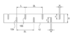
- FIG. 2 is a diagram showing a second flat plate constituting the core material of the present embodiment.
- FIG. 3 is a diagram illustrating an assembly process (first process) of the core material.
- FIG. 4 is a diagram illustrating an assembling process (second step) of the core material.
- FIG. 5 is a diagram illustrating an assembling process (third step) of the core material.
- FIG. 6 is a plan view of the core material.
- FIG. 7 is a diagram illustrating a conventional method for producing a core material.
- FIG. 8 is a diagram illustrating a conventional method for producing a core material.
- FIG. 9 is a diagram showing portions of conventional honeycomb cores having different wall thicknesses.
- FIG. 10 is a diagram showing a structure using the core material of the present embodiment.
- FIG. 11 is a plan view showing another example of the core material of the present embodiment.
- FIG. 1 is a diagram showing a first flat plate 11 which is a flat member constituting a honeycomb-shaped core material in the present embodiment.
- FIG. 2 is a diagram showing a second flat plate 12 which is a flat member constituting the honeycomb-shaped core material in the present embodiment.
- a plurality of first flat plates 11 are opened on one long side (upper edge side in FIG. 1) of a rectangular plate-shaped member and are parallel to the short side of the plate-shaped member. It has a comb-tooth shape (single comb-tooth shape) having a notch 11a.
- the cuts 11a are formed at equal intervals with a constant period L in the long side direction.
- the length f of the notch 11a is slightly longer than half the length g of the short side. Further, the width w of the notch 11a is wider than the plate thickness of the first flat plate 11.
- the second flat plate 12 opens on one long side (lower edge side in FIG. 2) of the rectangular plate-shaped member and is parallel to the short side of the plate-shaped member.
- a comb tooth having a plurality of notches 12a and a plurality of notches 12b open on the other long side (upper edge side in FIG. 2) of the rectangular plate-shaped member and parallel to the short side of the plate-shaped member. It has a shape (both comb teeth).
- the cuts 12a and the cuts 12b are formed at equal intervals in the long side direction with a constant period of 2L. Further, the notch 12a and the notch 12b are formed so as to be offset by a half cycle L in the long side direction.
- the cuts 12a and the cuts 12b are alternately formed in the long side direction at a constant period L.
- the length f and width w of the notch 12a are equal to the length f and width w of the notch 11a of the first flat plate 11.
- the plate thicknesses of the first flat plate 11 and the second flat plate 12 are equal.
- the thickness of the first flat plate 11 and the second flat plate 12 can be such that the first flat plate 11 and the second flat plate 12 are self-supporting (for example, 1 mm or more). ..
- the plate thickness of the first flat plate 11 and the second flat plate 12 can be appropriately set according to the required strength.
- the first flat plate 11 and the second flat plate 12 can be made of carbon fiber reinforced plastic (CFRP).
- CFRP is composed of a plurality of prepregs laminated.
- the prepreg is a sheet-like member in which carbon fibers are impregnated with resin while maintaining the directionality of the fibers.
- the resin constituting the prepreg is, for example, a thermosetting epoxy resin.
- a thermosetting resin such as unsaturated polyester, vinyl ester, phenol, cyanate ester, or polyimide can be used.
- CFRP CFRP
- a plurality of prepregs are laminated in a mold so as to have different fiber directions (for example, 8 to 24 layers), heated to about 120 ° C. to 130 ° C. under reduced pressure, and pressurized. It is molded by (crimping) and curing.
- a UD UNI-DIRECTION
- the UD material is a material in which the direction of the fiber extends in only one direction.
- the CFRP constituting the first flat plate 11 and the second flat plate 12 can be a cross-ply laminated plate in which prepregs are laminated so that the direction of the fibers is 0 ° / 90 °. More specifically, the CFRP can be a symmetrical cross-ply laminated plate in which the lamination is vertically symmetrical with respect to the central surface. In FIGS. 1 and 2, the directions of the fibers are the vertical direction and the horizontal direction.
- the CFRP produced in this way is a high-strength material while having a lower density (that is, lighter weight) than a metal material such as iron or aluminum. In addition, the material is pseudo-isotropic.
- the plurality of first flat plates 11 and the plurality of second flat plates 12 are fitted.
- first flat plate 11A a plurality of first flat plates 11 (hereinafter, referred to as "first flat plate 11A") with the opening of the notch 11a facing upward are arranged side by side in parallel.
- first flat plate 11A a plurality of first flat plates 11 with the opening of the notch 11a facing upward are arranged side by side in parallel.
- the plurality of first flat plates 11A are arranged side by side in parallel with respect to the plane of the first flat plate 11A at an interval of 2L (twice the period of the notch 11a) in the direction of 60 °.
- the plurality of second flat plates 12 are fitted to the plurality of first flat plates 11A arranged in the first step. Specifically, the notch 12a that opens to the lower side of the second flat plate 12 is aligned with the notch 11a of the first flat plate 11A and inserted. The portion where the first flat plate 11A and the second flat plate 12 are fitted is not adhered.
- the plurality of second flat plates 12 are arranged side by side in parallel with respect to the plane of the second flat plate 12 at a distance of 2 L in the direction of 60 °. At this time, the intersection angle ⁇ between the first flat plate 11A and the second flat plate 12 shown in FIG. 4 is 60 °.
- the notches 12a of the second flat plate 12 are inserted every other notch 11a of the first flat plate 11A.
- the first flat plate 11 with the opening of the notch 11a facing downward (hereinafter, "the first”.
- a plurality of flat plates 11B ") are fitted together.
- the first flat plate 11B is made with respect to the notch 11a in which the second flat plate 12 is not inserted in the first flat plate 11A and the notch 12b that opens above the second flat plate 12. Align the notch 11a and insert it. The portion where the first flat plate 11A and the first flat plate 11B are fitted and the portion where the second flat plate 12 and the first flat plate 11B are fitted are not adhered to each other.
- the plurality of first flat plates 11B are arranged side by side in parallel with respect to the plane of the first flat plate 11B at a distance of 2 L in the direction of 60 °. Further, the intersection angle ⁇ ′ between the first flat plate 11A and the first flat plate 11B and the intersection angle ⁇ ′′ between the second flat plate 12 and the first flat plate 11B shown in FIG. 5 are both 60. It becomes °. As described above, the honeycomb-shaped core material 10 is manufactured.
- the first flat plate 11 shown in FIG. 1 is used in the first step and the third step in the assembling step of the core material 10.
- the second flat plate 12 shown in FIG. 2 is used only in the second step. Therefore, the number of the first flat plates 11 used for the core material 10 is larger than the number of the second flat plates 12.
- FIG. 6 is a plan view of the honeycomb-shaped core material 10 of the present embodiment.
- the core material 10 is composed of a plurality of first flat plates 11A and 11B and a plurality of second flat plates 12.
- the plurality of flat plates are fitted with cuts so as to intersect each other at an angle of 60 °, and the core material 10 is formed into a regular hexagon by the first flat plates 11A and 11B and the second flat plate 12.
- a plurality of hexagonal tubular portions 13 having a shape and a plurality of triangular tubular portions 14 having a regular triangular shape are formed.
- a normal honeycomb core is an aggregate of regular hexagonal cells when viewed in a plan view, but the core material 10 in the present embodiment has a shape in which equilateral triangular cells are arranged around the regular hexagonal cells. .. Therefore, the core material 10 of the present embodiment cannot be called a honeycomb core, but becomes a honeycomb-shaped core (pseudo-honeycomb core), but can obtain the same strength as a normal honeycomb core. Further, since the core material 10 of the present embodiment is made of CFRP, it can be a honeycomb-shaped core material having CFRP characteristics such as high specific rigidity and low density and coefficient of thermal expansion.
- a panel or a flat stage is made as a structure using a honeycomb core as a core material
- plate-shaped members are attached above and below the core material.
- the inside of the hexagonal cylinder portion of the honeycomb core is completely sealed by this plate-shaped member.
- a thermosetting adhesive is generally used for attaching the plate-shaped member, and the honeycomb core is heated at the time of attachment. If the inside of the honeycomb core is sealed, a pressure difference may occur between the inside and outside of the sealed space when the temperature is lowered after the plate-shaped member is attached, and the structure may be distorted. is there. Further, even when the structure is used, the above pressure difference may occur due to a change in the environmental temperature, and the structure may be distorted. In order to prevent the inside of the hexagonal cylinder from being completely sealed, it is necessary to form a leak hole leading to the outside in the wall constituting the hexagonal cylinder, which further complicates the manufacturing process.
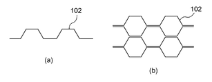
- CFRP members 102 bent in a zigzag pattern at equal intervals as shown in FIG. 8 (a) are partially bonded to each other as shown in FIG. 8 (b) to form a hexagon.
- a manufacturing method for forming a tubular portion can also be used.
- a dedicated processing device is required in order to bend the flat member at equal intervals as shown in FIG. 8A. Further, it is necessary to form a hole for leakage as in the honeycomb core shown in FIG. 7 (b).
- two flat members are bonded to the honeycomb core created by bonding the CFRP members 102 as shown in FIG. 8B, and the wall thickness is two.
- the overlapping part (the part marked with a circle in the figure) and the part made of one flat member are mixed.
- the direction parallel to the wall with double thickness ribbon direction
- the direction orthogonal to the first direction is the second direction
- the strength, rigidity, thermal expansion rate, etc. of this honeycomb core The mechanical and thermal properties are different in the first and second directions. This becomes a problem when the honeycomb core is used as a core material of a stage of a processing apparatus that requires precise processing accuracy, for example. This is because the stage surface may be distorted due to the force applied to the stage, the temperature change of the environment in which the device is placed, or the like.
- the core material 10 of the present embodiment is formed by fitting the cuts together so that the comb-shaped flat plates intersect with each other, there is no portion where the flat plates are doubled.
- the flat plates are in contact with each other, but they are in partial contact, and the two flat plates are firmly bonded to each other by an adhesive or the like. It is not fixed. Therefore, there is no anisotropy of the mechanical and thermal properties as in the honeycomb core shown in FIG. 8 (b), and the mechanical and thermal properties are the same in the first direction and the second direction. That is, it is possible to suppress the occurrence of strain due to temperature changes and the like.
- the core material 10 of the present embodiment can be created only by fitting the notches of the flat plate having a comb-teeth shape. Therefore, no special dedicated processing device or assembly device is required, and the production can be performed at low cost.
- the length f of the notch formed in the flat plate can be longer than half of the length g of the short side of the flat plate. As a result, a gap can be formed at the intersection (cut portion) of the two flat plates. This gap has the function of the leak hole described above. That is, the notch formed to intersect the flat plates also functions as a leak hole.
- the insides of the hexagonal cylinder portion 13 and the triangular cylinder portion 14 of the core material 10 are not sealed to the outside. Therefore, the step of forming the leak hole again becomes unnecessary, and the manufacturing time and cost of the core material 10 can be shortened.
- the width w of the notch formed in the flat plate is made wider than the plate thickness of the flat plate.
- the width w of the notch is set to the width at which a gap is formed in the notch portion in a state where the two flat plates are fitted at a predetermined angle.
- the play is preferably set in consideration of the manufacturing dimensional error of the plate thickness of the flat plate. Further, if the notch width w is too wide (play is too large), the initial posture when the flat plate is assembled becomes slanted, and the core material tends to buckle. Therefore, it is preferable to set the play width w of the notch so small that the buckling does not occur (the initial posture does not become slanted).
- the core material 10 in the present embodiment has the same mechanical and thermal characteristics in the plane orthogonal to the thickness direction, does not require a dedicated processing device, and does not require hole processing for leaks. It can be a honeycomb-shaped core material.
- the core material 10 in this embodiment can be used as a core material for various structures.
- the plate-shaped members 21 are arranged so as to sandwich the core material 10 from above and below, and the core material 10 is bonded to both sides of the core material 10 by using the adhesive members 22 to form a panel-shaped structure 20.
- the adhesive member 22 may be a sheet-shaped adhesive or a liquid adhesive.
- the core material 10 and the plate-shaped member 21 are made of the same material. By using the same material, the coefficient of thermal expansion of the core material 10 and the plate-shaped member 21 becomes the same, and distortion of the structure 20 due to a temperature change can be suppressed.
- the material of the core material 10 and the plate-shaped member 21 is CFRP, it is possible to form a strong panel-shaped structure 20 that is lightweight and has little thermal deformation (thermal expansion).
- CFRP has a small coefficient of thermal expansion in the direction parallel to the fiber, and the fluctuation (strain) due to heat is small. Therefore, by setting the direction of the CFRP fibers to be parallel to the short side of the flat plate serving as the core material 10, the surface fluctuation in the direction orthogonal to the surface of the plate-shaped member 21 due to the temperature change ( Deformation and distortion) can be prevented.
- the CFRP constituting the flat plate serving as the core material 10 is an example of a cross-ply laminated plate in which prepregs are laminated so that the fiber direction is at an angle of 0 ° / 90 °.
- the ones laminated at an intermediate 45 ° / 60 ° angle may be used. If the CFRP laminated in this way is used, the core material 10 can be made isotropic in terms of rigidity and expansion / contraction, and the applications for use are broadened.
- Such a structure 20 can be used, for example, for a building wall, an aircraft fuselage, a space device, a stage of a large processing device, or the like.
- the core material 10 is formed with the hexagonal tubular portion 13 having a regular hexagonal shape and the triangular tubular portion 14 having a regular triangular shape has been described, but the hexagonal tubular portion 13 and the triangular tubular portion 14 have been described. , Not limited to regular hexagons and regular triangles.
- the core material 10A on which the hexagonal cylinder portion 13A and the triangular cylinder portion 14A as shown in FIG. 11 can be formed.
- the core material 10A shown in FIG. 11 is composed of a first flat plate 11A, a second flat plate 12, and a third flat plate 15.
- the third flat plate 15 has the same configuration as the first flat plate 11B except that the notch spacing is different from that of the first flat plate 11B described above.
- the intersection angle ⁇ between the first flat plate 11A and the second flat plate 12 is 120 °
- the intersection angle ⁇ ′ between the first flat plate 11A and the third flat plate 15 is The angle of intersection between the second flat plate 12 and the third flat plate 15 is 30 °
- the distance between the third flat plates 15 is L.
- the crossing angle of the flat plates is not limited to the above and may be any angle. it can.
- the flat plates are crossed and fitted at an angle of 60 °, a core material having excellent stability can be obtained, which is preferable.
- the honeycomb-shaped core material 10 is formed by using two types of flat plates has been described, but the honeycomb-shaped core material may be formed by using three or more types of flat plates. ..
- the second flat member is formed by shifting the cuts at equal intervals by half a cycle.
- the cuts formed may not be at equal intervals or may be offset by half a cycle.
- the cross sections of the triangular cylinders formed around the hexagonal cylinders have different sizes. There is no problem in the strength of the core material of the triangular cylinder portion even if the size is slightly different.
Landscapes
- Engineering & Computer Science (AREA)
- Architecture (AREA)
- Civil Engineering (AREA)
- Structural Engineering (AREA)
- Mechanical Engineering (AREA)
- Aviation & Aerospace Engineering (AREA)
- Life Sciences & Earth Sciences (AREA)
- Wood Science & Technology (AREA)
- Laminated Bodies (AREA)
- Panels For Use In Building Construction (AREA)
Abstract
簡易的に作成可能なハニカム状の芯材およびその芯材を用いた構造体が開示される。 芯材(10)は、長方形の板状部材の長辺側に開口し、当該板状部材の短辺に対して平行な複数の切り込みを有する櫛歯状をなす複数の平面部材(複数の第一の平面板(11)と複数の第二の平面板(12))を有し、複数の平面部材が互いに交差するように切り込み同士が嵌め合わされることで、複数の平面部材によって、六角筒状の複数の第一筒部(13)と三角筒状の複数の第二筒部(14)とが形成されている。
Description
本発明は、ハニカム状の芯材、および、その芯材を用いた構造体に関する。
従来、軽量で強固な芯材として、六角形状のセル(六角筒)の集合体であるハニカムコアが知られている。ハニカムコアは、多くの構造体の芯材として用いられている。例えば、ハニカムコアを芯材とし、ハニカムコアの両面に板状部材を貼り付けることで、パネル状の構造体とすることができる。このような構造体は、例えば建築物の壁、航空機の機体、大型の加工装置のステージに使用される。
紙、アルミ、プラスチックといった素材によってハニカムコアを構成する場合、当該素材の両面に線状に接着剤を塗布して積層していき、ブロック状になった積層体を必要な幅で断裁し拡げることで、ハニカムコアを製造することができる。
紙、アルミ、プラスチックといった素材によってハニカムコアを構成する場合、当該素材の両面に線状に接着剤を塗布して積層していき、ブロック状になった積層体を必要な幅で断裁し拡げることで、ハニカムコアを製造することができる。
しかしながら、ハニカムコアを、比剛性が高く、かつ密度および熱膨張係数が小さいといった特性を有する炭素繊維強化プラスチック(Carbon Fiber Reinforced Plastic:CFRP)により構成しようとした場合、上記の製法を採用することはできない。
例えば特許文献1(特許第2676738号公報)には、円筒形の中空部を有する円筒状のCFRP、もしくは円筒形の中空部を有する六角筒状のCFRPを、多数並べて接着剤で接合した構造の芯材が開示されている。
例えば特許文献1(特許第2676738号公報)には、円筒形の中空部を有する円筒状のCFRP、もしくは円筒形の中空部を有する六角筒状のCFRPを、多数並べて接着剤で接合した構造の芯材が開示されている。
上記特許文献1(特許第2676738号公報)に記載の技術では、CFRPを円筒状もしくは六角筒状に成形し、成形したCFRPを多数並べて接着する必要があるため、製造工程が複雑である。また、特別な専用の加工装置や組み立て装置が必要となり、その分コストが嵩む。
そこで、本発明は、簡易的に作成可能なハニカム状の芯材およびその芯材を用いた構造体を提供することを目的とする。
そこで、本発明は、簡易的に作成可能なハニカム状の芯材およびその芯材を用いた構造体を提供することを目的とする。
上記課題を解決するために、本発明に係る芯材の一態様は、長方形の板状部材の長辺側に開口し、当該板状部材の短辺に対して平行な複数の切り込みを有する櫛歯状をなす複数の平面部材を有し、前記複数の平面部材が互いに交差するように前記切り込み同士が嵌め合わされることで、前記複数の平面部材によって、六角筒状の複数の第一筒部と三角筒状の複数の第二筒部とが形成されている。
このように、櫛歯状をなす平面部材同士を切り込みの部分で交差させて組み合わせただけの簡易な構成のハニカム状の芯材とすることできる。したがって、専用の加工装置や組み立て装置を必要とすることなく、簡易的に芯材を作成可能である。また、平面部材が二重になる部分(壁の厚さが二倍になる部分)とそうでない部分(平面部材が一枚である部分)とが混在しないため、芯材の厚さ方向に対して直交する面内における機械的特性および熱的特性を等しくすることができる。そのため、温度変化等による芯材のゆがみを抑制することができる。
このように、櫛歯状をなす平面部材同士を切り込みの部分で交差させて組み合わせただけの簡易な構成のハニカム状の芯材とすることできる。したがって、専用の加工装置や組み立て装置を必要とすることなく、簡易的に芯材を作成可能である。また、平面部材が二重になる部分(壁の厚さが二倍になる部分)とそうでない部分(平面部材が一枚である部分)とが混在しないため、芯材の厚さ方向に対して直交する面内における機械的特性および熱的特性を等しくすることができる。そのため、温度変化等による芯材のゆがみを抑制することができる。
また、上記の芯材において、前記複数の平面部材は、60°の角度で交差させて嵌め合わされていてもよい。
この場合、第一の筒部を正六角形状の六角筒部、第二の筒部を正三角形状の三角筒部とすることができる。したがって、安定性に優れた芯材とすることができる。
この場合、第一の筒部を正六角形状の六角筒部、第二の筒部を正三角形状の三角筒部とすることができる。したがって、安定性に優れた芯材とすることができる。
さらに、上記の芯材において、前記櫛歯状をなす複数の平面部材は、一方の前記長辺側に開口する複数の前記切り込みが等間隔に形成された片櫛歯状をなす複数の第一の平面部材と、一方の前記長辺側に開口する複数の前記切り込みと、他方の前記長辺側に開口する複数の前記切り込みとが、それぞれ等間隔に半周期ずれて形成された両櫛歯状をなす第二の平面部材と、を備えていてもよい。
この場合、二種類の平面部材だけでハニカム状の芯材を構成することができる。
この場合、二種類の平面部材だけでハニカム状の芯材を構成することができる。
また、上記の芯材において、前記切り込みの長さは、前記板状部材の短辺の長さの半分よりも長くてもよい。
この場合、平面部材同士を嵌め合わせた状態において、切り込み部分に隙間を形成することができる。つまり、第一筒部および第二筒部の内部を密閉しないようにすることができる。これにより、筒部に通気性を持たせることができ、温度変化による筒部内部の圧力変化に起因して芯材にゆがみが生じることを抑制することができる。
この場合、平面部材同士を嵌め合わせた状態において、切り込み部分に隙間を形成することができる。つまり、第一筒部および第二筒部の内部を密閉しないようにすることができる。これにより、筒部に通気性を持たせることができ、温度変化による筒部内部の圧力変化に起因して芯材にゆがみが生じることを抑制することができる。
さらに、上記の芯材において、前記切り込みの幅は、前記平面部材を嵌め合わせた状態において、前記切り込みの部分に隙間が形成される幅に設定されていてもよい。
この場合にも、第一筒部および第二筒部の内部を密閉しないようにすることができ、温度変化による筒部内部の圧力変化に起因して芯材にゆがみが生じることを抑制することができる。また、平面部材同士を嵌め合わせた際に、平面部材が切り込み部分で曲がってしまうのを防止することができる。
この場合にも、第一筒部および第二筒部の内部を密閉しないようにすることができ、温度変化による筒部内部の圧力変化に起因して芯材にゆがみが生じることを抑制することができる。また、平面部材同士を嵌め合わせた際に、平面部材が切り込み部分で曲がってしまうのを防止することができる。
また、上記の芯材において、前記平面部材は、複数のプリプレグが積層された炭素繊維強化プラスチックにより構成されていてもよい。この場合、比剛性が高く、かつ密度および熱膨張係数が小さいといった炭素繊維強化プラスチック(CFRP)の特性を有するハニカム状の芯材とすることができる。
また、上記の芯材において、炭素繊維強化プラスチックの繊維の方向は、平面部材の短辺に平行な方向であってもよい。この場合、温度変化に起因する、平面部材の短辺への変動(歪)を防ぐことができる。
さらにまた、上記の芯材において、前記炭素繊維強化プラスチックは、クロスプライ積層板であってもよい。この場合、疑似的に等方性を持たせることができる。
また、上記の芯材において、炭素繊維強化プラスチックの繊維の方向は、平面部材の短辺に平行な方向であってもよい。この場合、温度変化に起因する、平面部材の短辺への変動(歪)を防ぐことができる。
さらにまた、上記の芯材において、前記炭素繊維強化プラスチックは、クロスプライ積層板であってもよい。この場合、疑似的に等方性を持たせることができる。
また、本発明に係る芯材の製造方法の一態様は、六角筒状の複数の第一筒部と三角筒状の複数の第二筒部とを有する芯材の製造方法であって、長方形の板状部材の長辺側に開口し、当該板状部材の短辺に対して平行な複数の切り込みを有する櫛歯状をなす複数の平面部材を準備する工程と、前記複数の平面部材が互いに交差するように前記切り込み同士を嵌め合わる工程と、を含む。
このように、櫛歯状をなす平面部材同士を切り込みの部分で交差させて組み合わせるだけで、ハニカム状の芯材を製造することができる。つまり、専用の加工装置や組み立て装置を必要とすることなく、簡易的に芯材を作成可能である。
このように、櫛歯状をなす平面部材同士を切り込みの部分で交差させて組み合わせるだけで、ハニカム状の芯材を製造することができる。つまり、専用の加工装置や組み立て装置を必要とすることなく、簡易的に芯材を作成可能である。
また、本発明に係る構造体の一態様は、上記のいずれかの芯材と、前記芯材の両面に接着された板状部材と、を備える。
このように、簡易的に作成可能ハニカム状の芯材を用いた構造体とすることができる。上記の芯材は、厚さ方向に対して直交する面内における機械的特性および熱的特性が等しいため、温度変化等によるゆがみが抑制された構造体とすることができる。
このように、簡易的に作成可能ハニカム状の芯材を用いた構造体とすることができる。上記の芯材は、厚さ方向に対して直交する面内における機械的特性および熱的特性が等しいため、温度変化等によるゆがみが抑制された構造体とすることができる。
本発明によれば、専用の加工装置や組み立て装置を必要とすることなく、簡易的に作成可能なハニカム状の芯材とすることができる。
上記した本発明の目的、態様及び効果並びに上記されなかった本発明の目的、態様及び効果は、当業者であれば添付図面及び請求の範囲の記載を参照することにより下記の発明を実施するための形態(発明の詳細な説明)から理解できるであろう。
上記した本発明の目的、態様及び効果並びに上記されなかった本発明の目的、態様及び効果は、当業者であれば添付図面及び請求の範囲の記載を参照することにより下記の発明を実施するための形態(発明の詳細な説明)から理解できるであろう。
以下、本発明の実施の形態を図面に基づいて説明する。
本実施形態では、図1および図2に示す二種類の平面部材を組み合わせたハニカム状の芯材について説明する。
図1は、本実施形態におけるハニカム状の芯材を構成する平面部材である第一の平面板11を示す図である。また、図2は、本実施形態におけるハニカム状の芯材を構成する平面部材である第二の平面板12を示す図である。
本実施形態では、図1および図2に示す二種類の平面部材を組み合わせたハニカム状の芯材について説明する。
図1は、本実施形態におけるハニカム状の芯材を構成する平面部材である第一の平面板11を示す図である。また、図2は、本実施形態におけるハニカム状の芯材を構成する平面部材である第二の平面板12を示す図である。
図1に示すように、第一の平面板11は、長方形の板状部材の一方の長辺側(図1では上縁側)に開口し、当該板状部材の短辺に対して平行な複数の切り込み11aを有する櫛歯状(片櫛歯状)をなす。切り込み11aは、長辺方向に一定の周期Lで等間隔に形成されている。切り込み11aの長さfは、短辺の長さgの半分よりもやや長い。また、切り込み11aの幅wは、第一の平面板11の板厚よりも広い。
また、図2に示すように、第二の平面板12は、長方形の板状部材の一方の長辺側(図2では下縁側)に開口し、当該板状部材の短辺に対して平行な複数の切り込み12aと、長方形の板状部材の他方の長辺側(図2では上縁側)に開口し、当該板状部材の短辺に対して平行な複数の切り込み12bとを有する櫛歯状(両櫛歯状)をなす。
この第二の平面板12においては、切り込み12aと切り込み12bとは、それぞれ長辺方向に一定の周期2Lで等間隔に形成されている。また、切り込み12aと切り込み12bとは、長辺方向に半周期Lだけずれて形成されている。つまり、切り込み12aと切り込み12bとは、長辺方向に一定の周期Lで交互に形成されている。切り込み12aの長さfおよび幅wは、第一の平面板11の切り込み11aの長さfおよび幅wと等しい。
この第二の平面板12においては、切り込み12aと切り込み12bとは、それぞれ長辺方向に一定の周期2Lで等間隔に形成されている。また、切り込み12aと切り込み12bとは、長辺方向に半周期Lだけずれて形成されている。つまり、切り込み12aと切り込み12bとは、長辺方向に一定の周期Lで交互に形成されている。切り込み12aの長さfおよび幅wは、第一の平面板11の切り込み11aの長さfおよび幅wと等しい。
ここで、第一の平面板11と第二の平面板12との板厚は等しい。なお、第一の平面板11および第二の平面板12の板厚は、第一の平面板11および第二の平面板12がそれぞれ自立する厚さ(例えば、1mm以上)とすることができる。この第一の平面板11および第二の平面板12の板厚は、必要とされる強度に応じて適宜設定することができる。
第一の平面板11および第二の平面板12は、炭素繊維強化プラスチック(CFRP)により構成することができる。
CFRPは、複数のプリプレグが積層されて構成されている。プリプレグは、炭素繊維に、繊維の方向性を持たせたまま樹脂を含浸させたシート状の部材である。プリプレグを構成する樹脂は、例えば熱硬化性のエポキシ樹脂である。なお、プリプレグを構成する樹脂としては、例えば、不飽和ポリエステル、ビニルエステル、フェノール、シアネートエステル、ポリイミド等の熱硬化性樹脂を用いることもできる。
CFRPは、複数のプリプレグが積層されて構成されている。プリプレグは、炭素繊維に、繊維の方向性を持たせたまま樹脂を含浸させたシート状の部材である。プリプレグを構成する樹脂は、例えば熱硬化性のエポキシ樹脂である。なお、プリプレグを構成する樹脂としては、例えば、不飽和ポリエステル、ビニルエステル、フェノール、シアネートエステル、ポリイミド等の熱硬化性樹脂を用いることもできる。
CFRPは、型の中に、複数のプリプレグを繊維の方向が異なるように、必要数層(例えば、8層~24層)積層し、減圧下で120℃~130℃程度に加熱し、加圧(圧着)して硬化させることで成形される。プリプレグとしては、例えば、UD(UNI-DIRECTION)材を使用することができる。ここで、UD材とは繊維の方向が一方向にのみ延びている材料のことである。
第一の平面板11および第二の平面板12を構成するCFRPは、プリプレグを繊維の方向が0°/90°の角度となるように積層したクロスプライ積層板とすることができる。より具体的には、当該CFRPは、積層が中央面に対して上下対称となっている対称クロスプライ積層板とすることができる。図1および図2において、繊維の方向は、上下方向と左右方向とである。
このようにして製作されたCFRPは、鉄やアルミなどの金属材料よりも低密度(即ち軽い)でありながら、高強度な材料となる。また、疑似的に等方性を持たせた材料となる。
このようにして製作されたCFRPは、鉄やアルミなどの金属材料よりも低密度(即ち軽い)でありながら、高強度な材料となる。また、疑似的に等方性を持たせた材料となる。
複数の第一の平面板11および複数の第二の平面板12を、互いに交差するように切り込み11aや切り込み12aの部分で嵌め合わせることで、複数の第一の平面板11および複数の第二の平面板12によって、六角筒状の複数の六角筒部(第一筒部)と、三角筒状の複数の三角筒部(第二筒部)とが形成されたハニカム状の芯材を作成することができる。
以下、本実施形態における芯材の組み立て工程について詳細に説明する。
ここでは、平面板11、12を60°の角度で交差させて嵌め合わせ、正六角筒部と正三角筒部とが形成されたハニカム状の芯材を作成する場合について説明する。
(第一の工程)
図3に示すように、切り込み11aの開口を上に向けた第一の平面板11(以下、「第一の平面板11A」という。)を、平行に複数並べて配置する。このとき、複数の第一の平面板11Aは、当該第一の平面板11Aの平面に対して60°の方向に2L(切り込み11aの周期の2倍)の間隔で、平行に並べて配置する。
ここでは、平面板11、12を60°の角度で交差させて嵌め合わせ、正六角筒部と正三角筒部とが形成されたハニカム状の芯材を作成する場合について説明する。
(第一の工程)
図3に示すように、切り込み11aの開口を上に向けた第一の平面板11(以下、「第一の平面板11A」という。)を、平行に複数並べて配置する。このとき、複数の第一の平面板11Aは、当該第一の平面板11Aの平面に対して60°の方向に2L(切り込み11aの周期の2倍)の間隔で、平行に並べて配置する。
(第二の工程)
図4に示すように、第一の工程において配置された複数の第一の平面板11Aに、複数の第二の平面板12を嵌め合わせる。具体的には、第一の平面板11Aの切り込み11aに対し、第二の平面板12の下側に開口する切り込み12aを合わせて差し込む。なお、第一の平面板11Aと第二の平面板12とを嵌め合わせた部分は接着しない。
複数の第二の平面板12は、当該第二の平面板12の平面に対して60°の方向に間隔2Lで、平行に並べて配置する。このとき、図4に示す第一の平面板11Aと第二の平面板12との交差角度θは60°となる。
第二の平面板12が有する切り込み12aは、第一の平面板11Aの切り込み11aに対して、一個おきに差し込まれる。
図4に示すように、第一の工程において配置された複数の第一の平面板11Aに、複数の第二の平面板12を嵌め合わせる。具体的には、第一の平面板11Aの切り込み11aに対し、第二の平面板12の下側に開口する切り込み12aを合わせて差し込む。なお、第一の平面板11Aと第二の平面板12とを嵌め合わせた部分は接着しない。
複数の第二の平面板12は、当該第二の平面板12の平面に対して60°の方向に間隔2Lで、平行に並べて配置する。このとき、図4に示す第一の平面板11Aと第二の平面板12との交差角度θは60°となる。
第二の平面板12が有する切り込み12aは、第一の平面板11Aの切り込み11aに対して、一個おきに差し込まれる。
(第三の工程)
図5に示すように、第二の工程において組み付けられた第一の平面板11Aおよび第二の平面板12に、切り込み11aの開口を下に向けた第一の平面板11(以下、「第一の平面板11B」という。)を、複数枚嵌め合わせる。具体的には、第一の平面板11Aにおいて第二の平面板12が差し込まれていない切り込み11aと、第二の平面板12の上側に開口する切り込み12bとに対し、第一の平面板11Bの切り込み11aを合わせて差し込む。なお、第一の平面板11Aと第一の平面板11Bとを嵌め合わせた部分、および、第二の平面板12と第一の平面板11Bとを嵌め合わせた部分は、接着しない。
このとき、複数の第一の平面板11Bは、当該第一の平面板11Bの平面に対して60°の方向に間隔2Lで、平行に並べて配置される。また、図5に示す第一の平面板11Aと第一の平面板11Bとの交差角度θ´、第二の平面板12と第一の平面板11Bとの交差角度θ″は、いずれも60°となる。
以上により、ハニカム状の芯材10が製造される。
図5に示すように、第二の工程において組み付けられた第一の平面板11Aおよび第二の平面板12に、切り込み11aの開口を下に向けた第一の平面板11(以下、「第一の平面板11B」という。)を、複数枚嵌め合わせる。具体的には、第一の平面板11Aにおいて第二の平面板12が差し込まれていない切り込み11aと、第二の平面板12の上側に開口する切り込み12bとに対し、第一の平面板11Bの切り込み11aを合わせて差し込む。なお、第一の平面板11Aと第一の平面板11Bとを嵌め合わせた部分、および、第二の平面板12と第一の平面板11Bとを嵌め合わせた部分は、接着しない。
このとき、複数の第一の平面板11Bは、当該第一の平面板11Bの平面に対して60°の方向に間隔2Lで、平行に並べて配置される。また、図5に示す第一の平面板11Aと第一の平面板11Bとの交差角度θ´、第二の平面板12と第一の平面板11Bとの交差角度θ″は、いずれも60°となる。
以上により、ハニカム状の芯材10が製造される。
このように、図1に示す第一の平面板11は、芯材10の組み立て工程のうち、第一の工程と第三の工程とで使用する。一方、図2に示す第二の平面板12は、第二の工程のみで使用する。そのため、芯材10に使用される第一の平面板11の枚数は、第二の平面板12の枚数よりも多い。
図6は、本実施形態のハニカム状の芯材10の平面図である。
この図6に示すように、芯材10は、複数の第一の平面板11A、11Bと、複数の第二の平面板12と、によって構成されている。これら複数の平面板は、互いに60°の角度で交差するように切り込み同士が嵌め合わされており、芯材10には、第一の平面板11A、11Bおよび第二の平面板12によって、正六角形状の複数の六角筒部13と、正三角形状の複数の三角筒部14とが形成されている。
この図6に示すように、芯材10は、複数の第一の平面板11A、11Bと、複数の第二の平面板12と、によって構成されている。これら複数の平面板は、互いに60°の角度で交差するように切り込み同士が嵌め合わされており、芯材10には、第一の平面板11A、11Bおよび第二の平面板12によって、正六角形状の複数の六角筒部13と、正三角形状の複数の三角筒部14とが形成されている。
通常のハニカムコアは、平面図としてみると、正六角形のセルの集合体であるが、本実施形態における芯材10は、正六角形のセルの周りに正三角形のセルが配置された形状となる。そのため、本実施形態の芯材10はハニカムコアとは呼べず、ハニカム状のコア(疑似的なハニカムコア)となるが、通常のハニカムコアと同様の強度を得ることができる。
また、本実施形態の芯材10は、CFRPにより構成されているため、比剛性が高く、かつ密度および熱膨張係数が小さいといったCFRPの特性を有するハニカム状の芯材とすることができる。
また、本実施形態の芯材10は、CFRPにより構成されているため、比剛性が高く、かつ密度および熱膨張係数が小さいといったCFRPの特性を有するハニカム状の芯材とすることができる。
通常のハニカムコアをCFRPにより構成する場合、図7(a)に示すような六角筒状のCFRP部材101を、図7(b)に示すように隙間なく並べて接着する製法が用いられる。しかしながら、この場合、CFRPを六角筒状に成形する工程や、成形したCFRP部材101を多数並べて接着する工程が必要であり、製造工程が複雑である。
また、ハニカムコアを芯材とした構造体としてパネルや平面ステージを作る場合、芯材の上下に板状部材を貼り付ける。このとき、ハニカムコアの六角筒部の内部は、この板状部材により完全に密閉されることになる。板状部材の貼り付けには、一般に熱硬化型の接着剤が用いられ、貼り付け時にハニカムコアは加熱される。ハニカムコアの内部が密閉されていると、板状部材の貼り付けを終えて温度を下げた際に、密閉空間の内部と外部とで圧力差が生じ、構造体にひずみが生じてしまうおそれがある。さらに、構造体の使用時においても、環境温度の変化によって上記の圧力差が生じ、構造体にひずみが生じてしまうおそれがある。
六角筒部の内部を完全に密閉しないようにするためには、六角筒部を構成する壁に、外部に通じるリーク用の穴を形成する必要があり、製造工程がさらに複雑となる。
六角筒部の内部を完全に密閉しないようにするためには、六角筒部を構成する壁に、外部に通じるリーク用の穴を形成する必要があり、製造工程がさらに複雑となる。
また、通常のハニカムコアをCFRPにより構成する場合、図8(a)に示すように等間隔でジグザグに折り曲げたCFRP部材102を、図8(b)に示すように部分的に接着して六角筒部を形成する製法を用いることもできる。
しかしながら、平面状の部材を図8(a)に示すように等間隔で折り曲げるためには、専用の加工装置が必要である。また、図7(b)に示すハニカムコアと同様に、リーク用の穴を形成する必要がある。
しかしながら、平面状の部材を図8(a)に示すように等間隔で折り曲げるためには、専用の加工装置が必要である。また、図7(b)に示すハニカムコアと同様に、リーク用の穴を形成する必要がある。
さらに、図8(b)に示すようにCFRP部材102を貼り合わせて作成されたハニカムコアには、図9に示すように、二枚の平面状の部材が貼り合わされて壁の厚さが二重になる部分(図中、丸印の部分)と、一枚の平面部材からなる部分と、が混在する。厚さが二重になる壁に対して平行な方向(リボン方向)を第一方向、第一方向に直交する方向を第二方向とした場合、このハニカムコアの強度、剛性、熱膨張率といった機械的特性および熱的特性は、第一方向と第二方向とで異なる。
このことは、ハニカムコアを、例えば精密な加工精度が求められる加工装置のステージの芯材として用いる場合において問題となる。ステージに加わる力や、装置が置かれている環境の温度変化等により、ステージ面に歪が生じるおそれがあるからである。
このことは、ハニカムコアを、例えば精密な加工精度が求められる加工装置のステージの芯材として用いる場合において問題となる。ステージに加わる力や、装置が置かれている環境の温度変化等により、ステージ面に歪が生じるおそれがあるからである。
これに対して、本実施形態の芯材10は、櫛歯状をなす平面板が互いに交差するように切り込み同士を嵌め合わせて構成するので、平面板が二重になる部分が存在しない。二枚の平面板が交差する部分(切り込みの部分)では、平面板同士は互いに接触はしているが、部分的な接触であり、また、二枚の平面板同士が接着剤等により強固に固定されているわけではない。
したがって、図8(b)に示すハニカムコアのような機械的特性および熱的特性の異方性はなく、第一方向と第二方向とで機械的特性および熱的特性は等しい。つまり、温度変化等による歪の 発生を抑制することができる。
したがって、図8(b)に示すハニカムコアのような機械的特性および熱的特性の異方性はなく、第一方向と第二方向とで機械的特性および熱的特性は等しい。つまり、温度変化等による歪の 発生を抑制することができる。
また、本実施形態の芯材10は、櫛歯状をなす平面板の切り込み同士を嵌め合わせるだけで作成することができる。したがって、特別な専用の加工装置や組み立て装置が不要であり、その分、低コストで作成することができる。
さらに、平面板に形成される切り込みの長さfは、平面板の短辺の長さgの半分よりも長くすることができる。これにより、二枚の平面板が交差する部分(切り込みの部分)に隙間を形成することができる。この隙間は、上述したリーク用の穴の機能を有する。つまり、平面板を交差させるために形成した切り込みが、リーク用の穴の働きを兼用する。したがって、芯材10の上下に板状部材を貼り付けたとしても、芯材10の六角筒部13および三角筒部14の内部が、外部に対して密閉されることがない。そのため、改めてリーク用の穴を形成する工程が不要となり、芯材10の製作時間の短縮とコストダウンを図ることができる。
さらに、平面板に形成される切り込みの長さfは、平面板の短辺の長さgの半分よりも長くすることができる。これにより、二枚の平面板が交差する部分(切り込みの部分)に隙間を形成することができる。この隙間は、上述したリーク用の穴の機能を有する。つまり、平面板を交差させるために形成した切り込みが、リーク用の穴の働きを兼用する。したがって、芯材10の上下に板状部材を貼り付けたとしても、芯材10の六角筒部13および三角筒部14の内部が、外部に対して密閉されることがない。そのため、改めてリーク用の穴を形成する工程が不要となり、芯材10の製作時間の短縮とコストダウンを図ることができる。
また、平面板に形成される切り込みの幅wは、平面板の板厚よりも広くする。具体的には、切り込みの幅wは、二枚の平面板を所定の角度で嵌め合わせた状態において、切り込みの部分に隙間が形成される幅に設定する。本実施形態のように二枚の平面板を60°の角度で交差させて嵌め合わせる場合、切り込みの幅wは、二枚の平面板を60°の角度で交差して嵌め合わせることができる幅(平面板の板厚(設計値)dと平面板の交差角度θ=60°とに基づいて算出される値)に、所定のあそび(マージン)を設けた値とする。当該あそびは、平面板の板厚の製造上の寸法誤差を考慮して設定することが好ましい。
さらに、切り込みの幅wが広すぎると(あそびが大きすぎると)、平面板を組み付けた際の初期姿勢が斜めになってしまい、座屈しやすい芯材となってしまう。したがって、切り込みの幅wのあそびは、上記座屈を起こさない程度(初期姿勢が斜めにならない程度)に小さく設定することが好ましい。
さらに、切り込みの幅wが広すぎると(あそびが大きすぎると)、平面板を組み付けた際の初期姿勢が斜めになってしまい、座屈しやすい芯材となってしまう。したがって、切り込みの幅wのあそびは、上記座屈を起こさない程度(初期姿勢が斜めにならない程度)に小さく設定することが好ましい。
以上のように、本実施形態における芯材10は、厚さ方向に対して直交する面内における機械的特性および熱的特性が等しく、専用の加工装置が不要で、リーク用の穴加工が不要であるハニカム状の芯材とすることができる。
本実施形態における芯材10は、さまざまな構造体の芯材として使用することができる。例えば、図10に示すように、芯材10を上下から挟むようにして板状部材21を配置し、芯材10の両面に接着部材22を用いて接着することにより、パネル状の構造体20とすることができる。
ここで、接着部材22は、シート状の接着剤であってもよいし、液状の接着剤であってもよい。また、芯材10と板状部材21とは、同じ材質のものを使用することが望ましい。同じ材質を使用することで、芯材10と板状部材21との熱膨張係数が同一となり、温度変化による構造体20の歪を抑制することができる。
芯材10と板状部材21との材質をCFRPとすれば、軽量で熱変形(熱膨張)が小さく強固なパネル状の構造体20を作ることができる。
ここで、接着部材22は、シート状の接着剤であってもよいし、液状の接着剤であってもよい。また、芯材10と板状部材21とは、同じ材質のものを使用することが望ましい。同じ材質を使用することで、芯材10と板状部材21との熱膨張係数が同一となり、温度変化による構造体20の歪を抑制することができる。
芯材10と板状部材21との材質をCFRPとすれば、軽量で熱変形(熱膨張)が小さく強固なパネル状の構造体20を作ることができる。
また、CFRPは、その繊維と平行な方向については熱膨張係数が小さく、熱による変動(歪)が小さい。したがって、CFRPの繊維の方向を、芯材10となる平面板の短辺と平行な方向とすることにより、温度変化に起因する、板状部材21の表面に対して直交する方向の表面変動(変形や歪)を防ぐことができる。
なお、本実施形態においては、芯材10となる平面板を構成するCFRPは、プリプレグを繊維の方向が0°/90°の角度となるように積層したクロスプライ積層板を例示したが、繊維の方向を0°/90°の角度だけでなく、それに加えて、その中間の45°/60°の角度に積層したものを使用してもよい。そのように積層したCFRPを使用すれば、芯材10の剛性や伸縮について等方性を持たせることができ、利用の用途がより幅広いものとなる。
このような構造体20は、例えば建築物の壁、航空機の機体、宇宙機器、大型の加工装置のステージなどに使用することができる。
なお、本実施形態においては、芯材10となる平面板を構成するCFRPは、プリプレグを繊維の方向が0°/90°の角度となるように積層したクロスプライ積層板を例示したが、繊維の方向を0°/90°の角度だけでなく、それに加えて、その中間の45°/60°の角度に積層したものを使用してもよい。そのように積層したCFRPを使用すれば、芯材10の剛性や伸縮について等方性を持たせることができ、利用の用途がより幅広いものとなる。
このような構造体20は、例えば建築物の壁、航空機の機体、宇宙機器、大型の加工装置のステージなどに使用することができる。
(変形例)
上記実施形態においては、芯材10に正六角形状の六角筒部13と、正三角形状の三角筒部14とが形成されている場合について説明したが、六角筒部13および三角筒部14は、正六角形状および正三角形状に限定されない。
例えば、図11に示すような六角筒部13Aおよび三角筒部14Aが形成された芯材10Aとすることもできる。この図11に示す芯材10Aは、第一の平面板11Aと、第二の平面板12と、第三の平面板15とによって構成されている。ここで、第三の平面板15は、上述した第一の平面板11Bと切り込みの間隔が異なることを除いては、第一の平面板11Bと同様の構成を有する。この芯材10Aにおいて、第一の平面板11Aと第二の平面板12との交差角度θは120°であり、第一の平面板11Aと第三の平面板15との交差角度θ´は30°であり、第二の平面板12と第三の平面板15との交差角度θ″は30°である。また、第三の平面板15同士の間隔はLである。
上記実施形態においては、芯材10に正六角形状の六角筒部13と、正三角形状の三角筒部14とが形成されている場合について説明したが、六角筒部13および三角筒部14は、正六角形状および正三角形状に限定されない。
例えば、図11に示すような六角筒部13Aおよび三角筒部14Aが形成された芯材10Aとすることもできる。この図11に示す芯材10Aは、第一の平面板11Aと、第二の平面板12と、第三の平面板15とによって構成されている。ここで、第三の平面板15は、上述した第一の平面板11Bと切り込みの間隔が異なることを除いては、第一の平面板11Bと同様の構成を有する。この芯材10Aにおいて、第一の平面板11Aと第二の平面板12との交差角度θは120°であり、第一の平面板11Aと第三の平面板15との交差角度θ´は30°であり、第二の平面板12と第三の平面板15との交差角度θ″は30°である。また、第三の平面板15同士の間隔はLである。
つまり、上記実施形態では、複数の平面板を60°の角度で交差させて嵌め合わせる場合について説明したが、平面板の交差角度は上記に限定されるものではなく、任意の角度とすることができる。ただし、各平面板を60°の角度で交差させて嵌め合わせた場合、安定性に優れた芯材とすることができるため、好ましい。
また、上記実施形態では、二種類の平面板を用いてハニカム状の芯材10を構成する場合について説明したが、三種類以上の平面板を用いてハニカム状の芯材を構成してもよい。
また、上記実施形態においては、第二の平面部材は、切込みを等間隔に半周期ずらして形成した。しかし、形成する切込みは、等間隔でなくても、また半周期のずれでなくてもかまわない。その場合、六角筒部の周囲に作られる三角筒部の断面が、異なる大きさとなる。三角筒部は、その大きさに多少違いがあっても芯材の強度には問題がない。
また、上記実施形態では、二種類の平面板を用いてハニカム状の芯材10を構成する場合について説明したが、三種類以上の平面板を用いてハニカム状の芯材を構成してもよい。
また、上記実施形態においては、第二の平面部材は、切込みを等間隔に半周期ずらして形成した。しかし、形成する切込みは、等間隔でなくても、また半周期のずれでなくてもかまわない。その場合、六角筒部の周囲に作られる三角筒部の断面が、異なる大きさとなる。三角筒部は、その大きさに多少違いがあっても芯材の強度には問題がない。
なお、上記において特定の実施形態が説明されているが、当該実施形態は単なる例示であり、本発明の範囲を限定する意図はない。本明細書に記載された装置及び方法は上記した以外の形態において具現化することができる。また、本発明の範囲から離れることなく、上記した実施形態に対して適宜、省略、置換及び変更をなすこともできる。かかる省略、置換及び変更をなした形態は、請求の範囲に記載されたもの及びこれらの均等物の範疇に含まれ、本発明の技術的範囲に属する。
10…芯材、11(11A、11B)…第一の平面板、11a…切り込み、12…第二の平面板、12a,12b…切り込み、13…六角筒部(第一筒部)、14…三角筒部(第二筒部)、15…第三の平面板、20…構造体、21…板状部材、22…接着部材
Claims (10)
- 長方形の板状部材の長辺側に開口し、当該板状部材の短辺に対して平行な複数の切り込みを有する櫛歯状をなす複数の平面部材を有し、
前記複数の平面部材が互いに交差するように前記切り込み同士が嵌め合わされることで、前記複数の平面部材によって、六角筒状の複数の第一筒部と三角筒状の複数の第二筒部とが形成されていることを特徴とする芯材。 - 前記複数の平面部材は、60°の角度で交差させて嵌め合わされていることを特徴とする請求項1に記載の芯材。
- 前記櫛歯状をなす複数の平面部材は、
一方の前記長辺側に開口する複数の前記切り込みが等間隔に形成された片櫛歯状をなす複数の第一の平面部材と、
一方の前記長辺側に開口する複数の前記切り込みと、他方の前記長辺側に開口する複数の前記切り込みとが、それぞれ等間隔に半周期ずれて形成された両櫛歯状をなす第二の平面部材と、
を備えることを特徴とする請求項1または2に記載の芯材。 - 前記切り込みの長さは、前記板状部材の短辺の長さの半分よりも長いことを特徴とする請求項1から3のいずれか1項に記載の芯材。
- 前記切り込みの幅は、前記平面部材を嵌め合わせた状態において、前記切り込みの部分に隙間が形成される幅に設定されていることを特徴とする請求項1から4のいずれか1項に記載の芯材。
- 前記平面部材は、複数のプリプレグが積層された炭素繊維強化プラスチックにより構成されていることを特徴とする請求項1から5のいずれか1項に記載の芯材。
- 前記炭素繊維強化プラスチックの繊維の方向は、前記平面部材の短辺に平行な方向であることを特徴とする請求項6に記載の芯材。
- 前記炭素繊維強化プラスチックは、クロスプライ積層板であることを特徴とする請求項6に記載の芯材。
- 六角筒状の複数の第一筒部と三角筒状の複数の第二筒部とを有する芯材の製造方法であって、
長方形の板状部材の長辺側に開口し、当該板状部材の短辺に対して平行な複数の切り込みを有する櫛歯状をなす複数の平面部材を準備する工程と、
前記複数の平面部材が互いに交差するように前記切り込み同士を嵌め合わる工程と、を含むことを特徴とする芯材の製造方法。 - 請求項1から8のいずれか1項に記載の芯材と、
前記芯材の両面に接着された板状部材と、を備えることを特徴とする構造体。
Priority Applications (4)
| Application Number | Priority Date | Filing Date | Title |
|---|---|---|---|
| EP20887381.0A EP4060140B1 (en) | 2019-11-14 | 2020-07-29 | Core member and method for its manufacture |
| CN202080079117.7A CN115210437A (zh) | 2019-11-14 | 2020-07-29 | 芯材和结构体 |
| US17/756,026 US12226986B2 (en) | 2019-11-14 | 2020-07-29 | Core material and structure |
| KR1020227018880A KR102745301B1 (ko) | 2019-11-14 | 2020-07-29 | 심재 및 구조체 |
Applications Claiming Priority (2)
| Application Number | Priority Date | Filing Date | Title |
|---|---|---|---|
| JP2019-205877 | 2019-11-14 | ||
| JP2019205877A JP7365203B2 (ja) | 2019-11-14 | 2019-11-14 | 芯材および構造体 |
Publications (1)
| Publication Number | Publication Date |
|---|---|
| WO2021095303A1 true WO2021095303A1 (ja) | 2021-05-20 |
Family
ID=75912016
Family Applications (1)
| Application Number | Title | Priority Date | Filing Date |
|---|---|---|---|
| PCT/JP2020/029075 Ceased WO2021095303A1 (ja) | 2019-11-14 | 2020-07-29 | 芯材および構造体 |
Country Status (6)
| Country | Link |
|---|---|
| US (1) | US12226986B2 (ja) |
| EP (1) | EP4060140B1 (ja) |
| JP (1) | JP7365203B2 (ja) |
| KR (1) | KR102745301B1 (ja) |
| CN (1) | CN115210437A (ja) |
| WO (1) | WO2021095303A1 (ja) |
Families Citing this family (3)
| Publication number | Priority date | Publication date | Assignee | Title |
|---|---|---|---|---|
| CN116749905A (zh) * | 2023-07-19 | 2023-09-15 | 奇瑞汽车股份有限公司 | 用于车辆的吸能装置及车辆 |
| CN220882697U (zh) * | 2023-08-22 | 2024-05-03 | 永丰余投资控股股份有限公司 | 一种梳形复合板、复合板以及板材连接结构 |
| CN118744569A (zh) * | 2024-07-22 | 2024-10-08 | 武汉现代精工机械股份有限公司 | 一种蜂窝板及其成型工艺 |
Citations (4)
| Publication number | Priority date | Publication date | Assignee | Title |
|---|---|---|---|---|
| US2676738A (en) | 1952-10-03 | 1954-04-27 | Herrick Helen | Harness for hearing aid units |
| JP2676738B2 (ja) | 1987-06-29 | 1997-11-17 | 三菱電機株式会社 | 繊維強化プラスチック製反射鏡 |
| JP2001262771A (ja) * | 2000-03-23 | 2001-09-26 | Daiken Trade & Ind Co Ltd | パネル用芯材及びそれを用いたパネル |
| JP2008212787A (ja) * | 2007-03-01 | 2008-09-18 | Denso Corp | 排ガス浄化フィルタ |
Family Cites Families (11)
| Publication number | Priority date | Publication date | Assignee | Title |
|---|---|---|---|---|
| US2490586A (en) * | 1948-04-21 | 1949-12-06 | Craige L Embree | Cellular structure |
| GB1177933A (en) * | 1966-02-11 | 1970-01-14 | British Gypsum Ltd | Building Panels with Cellular Core |
| US4917934A (en) | 1989-04-27 | 1990-04-17 | Corning Incorporated | Telescope mirror blank and method of production |
| JP3231570B2 (ja) | 1995-02-01 | 2001-11-26 | 昭和飛行機工業株式会社 | 繊維強化プラスチック製のハニカム構造体 |
| US5741445A (en) | 1996-02-06 | 1998-04-21 | Cvd, Incorporated | Method of making lightweight closed-back mirror |
| JP3434254B2 (ja) * | 1999-12-27 | 2003-08-04 | 侃 田代 | 立体トラス複合板 |
| CN1301850C (zh) * | 2004-02-18 | 2007-02-28 | 冷鹭浩 | 一种矩形塑料蜂窝内芯复合板 |
| US10093039B2 (en) * | 2013-03-08 | 2018-10-09 | Stratasys, Inc. | Three-dimensional parts having interconnected Hollow patterns, method of manufacturing and method of producing composite part |
| EP2783838B1 (en) * | 2013-03-27 | 2015-11-18 | Airbus Operations GmbH | Composite reinforcement component, structural element, aircraft or spacecraft and method for producing a composite reinforcement component |
| DE102015010436B4 (de) | 2015-08-14 | 2019-01-24 | Airbus Defence and Space GmbH | Wabenkern für dimensionsstabile Sandwichbauteile, dessen Verwendung, Sandwichplatte mit diesem Wabenkern und Verfahren zur Herstellung des Wabenkerns |
| CN205149038U (zh) * | 2015-10-12 | 2016-04-13 | 重庆市皓邦工业有限公司 | 组合式纸蜂窝夹心复合板 |
-
2019
- 2019-11-14 JP JP2019205877A patent/JP7365203B2/ja active Active
-
2020
- 2020-07-29 WO PCT/JP2020/029075 patent/WO2021095303A1/ja not_active Ceased
- 2020-07-29 US US17/756,026 patent/US12226986B2/en active Active
- 2020-07-29 CN CN202080079117.7A patent/CN115210437A/zh active Pending
- 2020-07-29 EP EP20887381.0A patent/EP4060140B1/en active Active
- 2020-07-29 KR KR1020227018880A patent/KR102745301B1/ko active Active
Patent Citations (4)
| Publication number | Priority date | Publication date | Assignee | Title |
|---|---|---|---|---|
| US2676738A (en) | 1952-10-03 | 1954-04-27 | Herrick Helen | Harness for hearing aid units |
| JP2676738B2 (ja) | 1987-06-29 | 1997-11-17 | 三菱電機株式会社 | 繊維強化プラスチック製反射鏡 |
| JP2001262771A (ja) * | 2000-03-23 | 2001-09-26 | Daiken Trade & Ind Co Ltd | パネル用芯材及びそれを用いたパネル |
| JP2008212787A (ja) * | 2007-03-01 | 2008-09-18 | Denso Corp | 排ガス浄化フィルタ |
Also Published As
| Publication number | Publication date |
|---|---|
| US20220396049A1 (en) | 2022-12-15 |
| JP2021079547A (ja) | 2021-05-27 |
| CN115210437A (zh) | 2022-10-18 |
| EP4060140B1 (en) | 2024-12-04 |
| US12226986B2 (en) | 2025-02-18 |
| JP7365203B2 (ja) | 2023-10-19 |
| KR102745301B1 (ko) | 2024-12-24 |
| EP4060140A4 (en) | 2023-12-20 |
| EP4060140A1 (en) | 2022-09-21 |
| KR20220092966A (ko) | 2022-07-04 |
Similar Documents
| Publication | Publication Date | Title |
|---|---|---|
| WO2021095303A1 (ja) | 芯材および構造体 | |
| US6110567A (en) | Composite structural panel having a face sheet reinforced with a channel stiffener grid | |
| US8431214B2 (en) | Composite structure having reinforced core and method of making same | |
| US8512853B2 (en) | Composite structure having reinforced core | |
| JP5617788B2 (ja) | 繊維強化複合材料 | |
| KR101207472B1 (ko) | 피라미드형 트러스 구조체를 이용한 샌드위치 판재 및 그 제작 방법 | |
| CN103144289A (zh) | 成形期间允许层板滑动的制造复合材料层合板结构的方法 | |
| CN105916673B (zh) | 复合材料构造 | |
| JP2025116355A (ja) | 格子状構造体および格子状構造体の製造方法 | |
| KR20040005553A (ko) | 내화 패널 및 이를 구비한 벽 구조의 제조 방법 | |
| US10844589B2 (en) | Laminate cell construction system | |
| JPH08184126A (ja) | Frp製構造材 | |
| JPH0885178A (ja) | ハニカムサンドイッチパネル | |
| Kocher et al. | Reinforced Cutouts in Graphite | |
| JP2012236386A (ja) | 集成材およびその製造方法 | |
| JP7559630B2 (ja) | ハニカムコア | |
| KR100620544B1 (ko) | 하니컴코아 | |
| KR200207288Y1 (ko) | 사각 격자형 알루미늄 허니컴 샌드위치 패널 | |
| JP2015168217A (ja) | 繊維強化プラスチック製の継手部材、及び繊維強化プラスチック製の継手部材の製造方法 | |
| JP2019069561A (ja) | ハニカム構造体およびその製造方法 | |
| JP2024138803A (ja) | 格子状構造体および格子状構造体の製造方法 | |
| JPS62220328A (ja) | ハニカムパネル構造体の製造法 | |
| JPH04315658A (ja) | コンクリート型枠用可撓性成形合板及び型枠組立工法 | |
| JPWO2021171529A5 (ja) | ||
| EP2821220A1 (en) | Composite honeycomb |
Legal Events
| Date | Code | Title | Description |
|---|---|---|---|
| 121 | Ep: the epo has been informed by wipo that ep was designated in this application |
Ref document number: 20887381 Country of ref document: EP Kind code of ref document: A1 |
|
| ENP | Entry into the national phase |
Ref document number: 20227018880 Country of ref document: KR Kind code of ref document: A |
|
| NENP | Non-entry into the national phase |
Ref country code: DE |
|
| ENP | Entry into the national phase |
Ref document number: 2020887381 Country of ref document: EP Effective date: 20220614 |