WO2021095871A1 - 積層造形システム、および積層造形方法 - Google Patents
積層造形システム、および積層造形方法 Download PDFInfo
- Publication number
- WO2021095871A1 WO2021095871A1 PCT/JP2020/042502 JP2020042502W WO2021095871A1 WO 2021095871 A1 WO2021095871 A1 WO 2021095871A1 JP 2020042502 W JP2020042502 W JP 2020042502W WO 2021095871 A1 WO2021095871 A1 WO 2021095871A1
- Authority
- WO
- WIPO (PCT)
- Prior art keywords
- gas
- chamber
- laminated
- purification tower
- powder material
- Prior art date
- Legal status (The legal status is an assumption and is not a legal conclusion. Google has not performed a legal analysis and makes no representation as to the accuracy of the status listed.)
- Ceased
Links
Images


Classifications
-
- B—PERFORMING OPERATIONS; TRANSPORTING
- B29—WORKING OF PLASTICS; WORKING OF SUBSTANCES IN A PLASTIC STATE IN GENERAL
- B29C—SHAPING OR JOINING OF PLASTICS; SHAPING OF MATERIAL IN A PLASTIC STATE, NOT OTHERWISE PROVIDED FOR; AFTER-TREATMENT OF THE SHAPED PRODUCTS, e.g. REPAIRING
- B29C64/00—Additive manufacturing, i.e. manufacturing of three-dimensional [3D] objects by additive deposition, additive agglomeration or additive layering, e.g. by 3D printing, stereolithography or selective laser sintering
- B29C64/30—Auxiliary operations or equipment
- B29C64/364—Conditioning of environment
- B29C64/371—Conditioning of environment using an environment other than air, e.g. inert gas
-
- B—PERFORMING OPERATIONS; TRANSPORTING
- B22—CASTING; POWDER METALLURGY
- B22F—WORKING METALLIC POWDER; MANUFACTURE OF ARTICLES FROM METALLIC POWDER; MAKING METALLIC POWDER; APPARATUS OR DEVICES SPECIALLY ADAPTED FOR METALLIC POWDER
- B22F10/00—Additive manufacturing of workpieces or articles from metallic powder
- B22F10/20—Direct sintering or melting
- B22F10/28—Powder bed fusion, e.g. selective laser melting [SLM] or electron beam melting [EBM]
-
- B—PERFORMING OPERATIONS; TRANSPORTING
- B22—CASTING; POWDER METALLURGY
- B22F—WORKING METALLIC POWDER; MANUFACTURE OF ARTICLES FROM METALLIC POWDER; MAKING METALLIC POWDER; APPARATUS OR DEVICES SPECIALLY ADAPTED FOR METALLIC POWDER
- B22F10/00—Additive manufacturing of workpieces or articles from metallic powder
- B22F10/30—Process control
- B22F10/32—Process control of the atmosphere, e.g. composition or pressure in a building chamber
-
- B—PERFORMING OPERATIONS; TRANSPORTING
- B22—CASTING; POWDER METALLURGY
- B22F—WORKING METALLIC POWDER; MANUFACTURE OF ARTICLES FROM METALLIC POWDER; MAKING METALLIC POWDER; APPARATUS OR DEVICES SPECIALLY ADAPTED FOR METALLIC POWDER
- B22F10/00—Additive manufacturing of workpieces or articles from metallic powder
- B22F10/70—Recycling
- B22F10/77—Recycling of gas
-
- B—PERFORMING OPERATIONS; TRANSPORTING
- B22—CASTING; POWDER METALLURGY
- B22F—WORKING METALLIC POWDER; MANUFACTURE OF ARTICLES FROM METALLIC POWDER; MAKING METALLIC POWDER; APPARATUS OR DEVICES SPECIALLY ADAPTED FOR METALLIC POWDER
- B22F12/00—Apparatus or devices specially adapted for additive manufacturing; Auxiliary means for additive manufacturing; Combinations of additive manufacturing apparatus or devices with other processing apparatus or devices
- B22F12/40—Radiation means
- B22F12/41—Radiation means characterised by the type, e.g. laser or electron beam
-
- B—PERFORMING OPERATIONS; TRANSPORTING
- B22—CASTING; POWDER METALLURGY
- B22F—WORKING METALLIC POWDER; MANUFACTURE OF ARTICLES FROM METALLIC POWDER; MAKING METALLIC POWDER; APPARATUS OR DEVICES SPECIALLY ADAPTED FOR METALLIC POWDER
- B22F12/00—Apparatus or devices specially adapted for additive manufacturing; Auxiliary means for additive manufacturing; Combinations of additive manufacturing apparatus or devices with other processing apparatus or devices
- B22F12/70—Gas flow means
-
- B—PERFORMING OPERATIONS; TRANSPORTING
- B29—WORKING OF PLASTICS; WORKING OF SUBSTANCES IN A PLASTIC STATE IN GENERAL
- B29C—SHAPING OR JOINING OF PLASTICS; SHAPING OF MATERIAL IN A PLASTIC STATE, NOT OTHERWISE PROVIDED FOR; AFTER-TREATMENT OF THE SHAPED PRODUCTS, e.g. REPAIRING
- B29C64/00—Additive manufacturing, i.e. manufacturing of three-dimensional [3D] objects by additive deposition, additive agglomeration or additive layering, e.g. by 3D printing, stereolithography or selective laser sintering
- B29C64/10—Processes of additive manufacturing
- B29C64/141—Processes of additive manufacturing using only solid materials
- B29C64/153—Processes of additive manufacturing using only solid materials using layers of powder being selectively joined, e.g. by selective laser sintering or melting
-
- B—PERFORMING OPERATIONS; TRANSPORTING
- B29—WORKING OF PLASTICS; WORKING OF SUBSTANCES IN A PLASTIC STATE IN GENERAL
- B29C—SHAPING OR JOINING OF PLASTICS; SHAPING OF MATERIAL IN A PLASTIC STATE, NOT OTHERWISE PROVIDED FOR; AFTER-TREATMENT OF THE SHAPED PRODUCTS, e.g. REPAIRING
- B29C64/00—Additive manufacturing, i.e. manufacturing of three-dimensional [3D] objects by additive deposition, additive agglomeration or additive layering, e.g. by 3D printing, stereolithography or selective laser sintering
- B29C64/30—Auxiliary operations or equipment
- B29C64/386—Data acquisition or data processing for additive manufacturing
- B29C64/393—Data acquisition or data processing for additive manufacturing for controlling or regulating additive manufacturing processes
-
- B—PERFORMING OPERATIONS; TRANSPORTING
- B33—ADDITIVE MANUFACTURING TECHNOLOGY
- B33Y—ADDITIVE MANUFACTURING, i.e. MANUFACTURING OF THREE-DIMENSIONAL [3D] OBJECTS BY ADDITIVE DEPOSITION, ADDITIVE AGGLOMERATION OR ADDITIVE LAYERING, e.g. BY 3D PRINTING, STEREOLITHOGRAPHY OR SELECTIVE LASER SINTERING
- B33Y10/00—Processes of additive manufacturing
-
- B—PERFORMING OPERATIONS; TRANSPORTING
- B33—ADDITIVE MANUFACTURING TECHNOLOGY
- B33Y—ADDITIVE MANUFACTURING, i.e. MANUFACTURING OF THREE-DIMENSIONAL [3D] OBJECTS BY ADDITIVE DEPOSITION, ADDITIVE AGGLOMERATION OR ADDITIVE LAYERING, e.g. BY 3D PRINTING, STEREOLITHOGRAPHY OR SELECTIVE LASER SINTERING
- B33Y30/00—Apparatus for additive manufacturing; Details thereof or accessories therefor
-
- B—PERFORMING OPERATIONS; TRANSPORTING
- B33—ADDITIVE MANUFACTURING TECHNOLOGY
- B33Y—ADDITIVE MANUFACTURING, i.e. MANUFACTURING OF THREE-DIMENSIONAL [3D] OBJECTS BY ADDITIVE DEPOSITION, ADDITIVE AGGLOMERATION OR ADDITIVE LAYERING, e.g. BY 3D PRINTING, STEREOLITHOGRAPHY OR SELECTIVE LASER SINTERING
- B33Y40/00—Auxiliary operations or equipment, e.g. for material handling
-
- B—PERFORMING OPERATIONS; TRANSPORTING
- B33—ADDITIVE MANUFACTURING TECHNOLOGY
- B33Y—ADDITIVE MANUFACTURING, i.e. MANUFACTURING OF THREE-DIMENSIONAL [3D] OBJECTS BY ADDITIVE DEPOSITION, ADDITIVE AGGLOMERATION OR ADDITIVE LAYERING, e.g. BY 3D PRINTING, STEREOLITHOGRAPHY OR SELECTIVE LASER SINTERING
- B33Y50/00—Data acquisition or data processing for additive manufacturing
- B33Y50/02—Data acquisition or data processing for additive manufacturing for controlling or regulating additive manufacturing processes
-
- B—PERFORMING OPERATIONS; TRANSPORTING
- B22—CASTING; POWDER METALLURGY
- B22F—WORKING METALLIC POWDER; MANUFACTURE OF ARTICLES FROM METALLIC POWDER; MAKING METALLIC POWDER; APPARATUS OR DEVICES SPECIALLY ADAPTED FOR METALLIC POWDER
- B22F2999/00—Aspects linked to processes or compositions used in powder metallurgy
-
- Y—GENERAL TAGGING OF NEW TECHNOLOGICAL DEVELOPMENTS; GENERAL TAGGING OF CROSS-SECTIONAL TECHNOLOGIES SPANNING OVER SEVERAL SECTIONS OF THE IPC; TECHNICAL SUBJECTS COVERED BY FORMER USPC CROSS-REFERENCE ART COLLECTIONS [XRACs] AND DIGESTS
- Y02—TECHNOLOGIES OR APPLICATIONS FOR MITIGATION OR ADAPTATION AGAINST CLIMATE CHANGE
- Y02P—CLIMATE CHANGE MITIGATION TECHNOLOGIES IN THE PRODUCTION OR PROCESSING OF GOODS
- Y02P10/00—Technologies related to metal processing
- Y02P10/25—Process efficiency
Definitions
- the present invention relates to a laminated modeling system and a laminated modeling method.
- Adaptive Manufacturing There is an additional manufacturing technique called Adaptive Manufacturing.
- a laminated molding apparatus in which a powder material such as resin or metal is formed into a layer having an arbitrary shape, and the formed layers are sequentially laminated to produce a laminated model having an arbitrary shape.
- a metal 3D printer that sinters metal powder on a molding stage with a laser or the like is known.
- sintered metal layers are sequentially laminated on a molding stage, and a structure having a complicated shape can be manufactured accurately in a short time. Therefore, metal 3D printers are attracting attention as promising technologies in advanced technology fields such as the aircraft industry and medical treatment (for example, Patent Document 1).
- the laminated molding apparatus described in Patent Document 1 forms a sintered body by irradiating a molding chamber filled with an inert gas and a predetermined portion of a powder material layer with a laser beam to sinter the powder material. It is provided with a laser beam irradiation unit.
- a conventional metal 3D printer such as the laminated molding apparatus described in Patent Document 1, it is general to improve the quality by controlling the parameters and characteristics of the laser beam, the thickness of the metal layer, and the like.
- the laminated modeling device is required to further improve the quality of the laminated model.
- the laminated modeling apparatus described in Patent Document 1 does not have a function of optimizing the concentration of gas components in the atmosphere in the modeling chamber according to the material of the metal powder.
- the present invention provides a laminated modeling system capable of further improving the quality of the laminated model.
- the present invention provides the following laminated modeling system.
- a laminated modeling system in which heat is supplied to a powder material using energy rays in the presence of a shield gas to form a layer, and the layers are sequentially laminated to produce a laminated model.
- the laminated modeling system includes a laminated modeling unit that forms the layers and sequentially laminates the layers, and a concentration adjusting unit that adjusts the concentration of gas components in the shield gas.
- the laminated modeling unit includes an irradiation unit including an irradiation source of energy rays to irradiate the powder material, a chamber filled with the shield gas, and a modeling unit including a modeling stage in which the layers are formed and laminated.
- the concentration adjusting unit has a purification unit that removes a first gas component that becomes an impurity in the shield gas according to the powder material, and a second gas component selected according to the powder material. It has a supply unit that supplies the inside of the chamber as needed.
- a first supply line for supplying a part of the shield gas in the chamber to the purification unit is further provided. At least one selected from the group consisting of the following first purification tower, second purification tower, third purification tower and fourth purification tower in which the purification unit is connected to the first supply line.
- the laminated molding system according to [1] which includes the above.
- First purification tower Purification tower for removing oxygen from the shield gas
- Second purification tower Purification tower for removing water from the shield gas
- Third purification tower Purification tower for removing nitrogen from the shield gas
- Fourth Purification tower A purification tower that removes water from the shield gas and does not remove oxygen [3]
- the purification unit has the following first bypass line, second bypass line, third bypass line, and fourth.
- First bypass line A bypass line second that supplies the shield gas supplied from the first supply line to the secondary side of the first purification tower without supplying it to the first purification tower.
- Bypass line Bypass line that supplies the shield gas supplied from the first supply line to the secondary side of the second purification tower without supplying it to the second purification tower.
- Third bypass line Bypass line that supplies the shield gas supplied from the first supply line to the secondary side of the third purification tower without supplying it to the third purification tower.
- Fourth bypass line The first Bypass line that supplies the shield gas supplied from the supply line of No. 4 to the secondary side of the fourth refining tower without supplying it to the fourth refining tower.
- the laminated molding system according to any one of [1] to [3], which comprises a source of one or more of the second gas components selected from the group consisting of carbon monoxide, carbon dioxide, and ammonia.
- a second supply line for supplying the gas from which the first gas component has been removed from the shield gas by the purification unit to the chamber is further provided, and the supply unit is in the second supply line.
- the laminated molding system according to any one of [1] to [4], further comprising a third supply line for supplying the second gas component to the gas as needed.
- a laminated molding method in which heat is supplied to a powder material using an energy ray to form a layer in the presence of a shield gas, and the layers are sequentially laminated to produce a laminated model. It has a step (a) of forming the layer and sequentially laminating the layer, and a step (b) of adjusting the concentration of a gas component in the shield gas.
- the powder material in the chamber is irradiated with energy rays, the layer is formed in the chamber, and the formed layers are sequentially laminated.
- the first gas component that becomes an impurity in the shield gas is removed according to the powder material, and a second gas component selected according to the powder material is required.
- a laminated molding method that supplies the inside of the chamber accordingly.
- at least one or more gas components selected from the group consisting of oxygen, water, and nitrogen are removed from the shield gas as the first gas component. Laminated molding method.
- step (b) one or more gas components selected from the group consisting of hydrogen, oxygen, carbon monoxide, carbon dioxide, and ammonia are supplied into the chamber as the second gas component.
- a laminated modeling system capable of further improving the quality of the laminated model.
- FIG. 1 It is a schematic diagram which shows an example of the structure of the laminated modeling system which concerns on one Embodiment example. It is a schematic diagram which shows the structure of the laminated modeling unit provided in the laminated modeling system of FIG. 1. It is a schematic diagram which shows the structure of the density
- the present laminated modeling system In the laminated modeling system according to the present embodiment (hereinafter referred to as "the present laminated modeling system"), heat is supplied to the powder material by using energy rays in the presence of a shield gas to form a layer, and the layer is formed.
- This laminated modeling system includes a laminated modeling unit and a density adjustment unit.
- the laminated molding unit in the presence of a shield gas, heat is supplied to the powder material using energy rays to form a layer, and the layers are sequentially laminated.
- the laminated modeling unit has an irradiation unit including an irradiation source of energy rays to irradiate the powder material, and a modeling unit including a chamber and a modeling stage.
- the chamber is filled with shield gas.
- the shield gas is an inert gas for reducing the oxygen concentration in the atmosphere around the powder material when irradiated with energy rays.
- the energy rays are not particularly limited. For example, a laser, an electron beam, and the like can be mentioned.
- the layers are formed by energy rays and the formed layers are laminated.
- the concentration adjustment unit adjusts the concentration of gas components in the shield gas.
- the concentration adjustment unit has a purification unit and a supply unit.
- the purification unit removes the first gas component, which is an impurity in the shield gas, depending on the powder material.
- the supply unit supplies a second gas component selected according to the powder material into the chamber as needed.
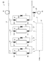
- FIG. 1 is a schematic view showing an example of the configuration of the present laminated modeling system.
- the laminated modeling system 70 shown in FIG. 1 includes a laminated modeling unit 10, a concentration adjusting unit 30, a filter unit 50, a first supply line L1, a second supply line L2, a circulation line L3, and an electromagnetic valve. It includes V1 to V3.
- the laminated modeling system 70 is a system in which heat is supplied to a powder material using energy rays to form a layer in the presence of a shield gas, and the layers are sequentially laminated to produce a laminated model.
- the laminated molding unit 10 supplies heat to the powder material using energy rays in the presence of a shield gas to form a layer, and the formed layers are sequentially laminated.
- the concentration adjusting unit 30 adjusts the concentration of the gas component in the shield gas.
- the filter unit 50 removes solid impurities such as fumes and spatters in the shield gas.
- the first supply line L1 supplies a part of the shield gas in the chamber 3 (details will be described later) included in the laminated modeling unit 10 to the purification unit of the concentration adjusting unit 30.
- the first supply line L1 connects the chamber 3 and the first purification tower 31, which will be described later.
- a solenoid valve V1 is provided in the first supply line L1. When the solenoid valve V1 is in the open state, the first supply line L1 supplies the shield gas in the chamber 3 to the purification unit of the concentration adjusting unit 30.
- the second supply line L2 supplies the gas from which the first gas component has been removed from the shield gas by the purification unit of the concentration adjustment unit 30 into the chamber 3.
- the second supply line L2 connects the fourth purification tower 34, which will be described later, with the chamber 3.
- a solenoid valve V2 is provided on the second supply line L2. When the solenoid valve V2 is in the open state, the second supply line L2 introduces a gas in the chamber 3 from which the first gas component, which is an impurity in the shield gas, has been removed from the shield gas by the purification unit of the concentration adjustment unit 30. Supply to.
- the circulation line L3 connects the first supply line L1 on the primary side of the solenoid valve V1 and the second supply line L2 on the secondary side of the solenoid valve V2.
- the upstream side in the direction in which the gas in the first supply line L1 flows from the laminated modeling unit 10 to the concentration adjusting unit 30 is the primary side
- the downstream side is the secondary side
- the upstream side in the direction in which the gas in the second supply line L2 flows from the concentration adjusting unit 30 to the laminated modeling unit 10 is the primary side
- the downstream side is the secondary side.
- a solenoid valve V3 is provided on the circulation line L3.
- the laminated molding system 70 introduces a part of the shield gas in the chamber 3 into the first supply line L1.
- the shield gas in the first supply line L1 is resupplied into the chamber 3 via the circulation line L3 and the second supply line L2 in this order.
- the laminated modeling system 70 introduces a part of the shield gas in the chamber 3 into the first supply line L1 and then into the concentration adjusting unit 30. It is supplied, and the remaining shield gas is supplied again into the chamber 3 via the second supply line L2.
- the solenoid valves V1 to V3 are electrically connected to the CPU 37 described later. The open / closed state of each solenoid valve can be controlled by the CPU 37.
- FIG. 2 is a schematic view showing the configuration of the laminated modeling unit 10 included in the laminated modeling system 70.
- the laminated modeling unit 10 includes a laser oscillator 1, an optical system 2, a chamber 3, a storage chamber 4, a modeling chamber 5, a recovery chamber 6, a recorder 7, a storage stage 8, and the like.
- the modeling stage 9, the first densitometer C1, and the second densitometer C2 are included.
- the laminated modeling unit 10 supplies heat to the powder material M on the modeling stage 9 by irradiating the laser L (an example of energy rays) with the laser oscillator 1 to form a layer, and the formed layers are sequentially laminated.
- Laminated model X Laminated model X.
- the laminated modeling unit 10 has an irradiation unit and a modeling unit.
- the irradiation unit includes an irradiation source of energy rays for irradiating the powder material M.
- the irradiation unit includes a laser oscillator 1 and an optical system 2.
- the modeling unit includes a chamber 3 filled with a shield gas and a modeling stage 9 in which layers are formed and laminated.
- the modeling unit includes a chamber 3, a modeling chamber 5, and a modeling stage 9.
- the irradiation unit of the laminated modeling unit 10 includes a laser oscillator 1 as an irradiation source of energy rays.
- the laser oscillator 1 is an example of an energy ray irradiation source. In another example of this embodiment, the irradiation source of the energy ray may be a form other than the laser oscillator.
- the laser oscillator 1 irradiates the powder material M with the laser L as an energy ray.
- the laser oscillator 1 is not particularly limited as long as it can irradiate the powder material M on the modeling stage 9 with the laser L.
- the laser oscillator 1 irradiates the powder material M in the chamber 3 with the laser L via the optical system 2.
- the laminated modeling unit 10 can sinter or melt and solidify the powder material M at the position irradiated with the laser L.
- a layer containing a sintered product of the powder material M or a melt-solidified product of the powder material M (hereinafter referred to as a “modeling layer”) is formed.
- the optical system 2 is not particularly limited as long as the irradiation position of the laser L on the powder material M on the modeling stage 9 can be controlled according to preset data.
- the optical system 2 for example, a system having one or more reflectors can be mentioned.
- the laminated modeling unit 10 can control the irradiation position of the laser L on the powder material M by controlling the optical system 2 according to preset data. As a result, the laminated modeling unit 10 can form a modeling layer having an arbitrary shape.
- Examples of the powder material M include powders of carbon, boron, magnesium, calcium, chromium, copper, iron, manganese, molybdenum, cobalt, nickel, hafnium, niobium, titanium, aluminum and the like.
- metals such as chromium, copper, iron, manganese, molybdenum, cobalt, nickel, hafnium, niobium, titanium, and aluminum, and powders of alloys thereof are preferable.
- Examples of alloys include stainless steel alloys and nickel alloys. Examples include aluminum alloys and titanium alloys.
- the particle size of the powder material M is not particularly limited, but can be, for example, about 10 to 200 ⁇ m.
- the modeling portion of the laminated modeling unit 10 includes a chamber 3, a modeling chamber 5, and a modeling stage 9.
- the storage chamber 4, the collection chamber 6, the recorder 7, and the storage stage 8 may also be regarded as the configuration of the modeling portion of the laminated modeling unit 10.
- Chamber 3 is a container filled with shield gas.
- the primary side end of the first supply line L1, the secondary end of the second supply line L2, and the secondary end of the shield gas supply line L4 are connected to the chamber 3, respectively. ..
- the end of the shield gas supply line L4 on the primary side (not shown) is connected to the supply source of the shield gas (not shown).
- the space inside the chamber 3 is filled with the shield gas via the shield gas supply line L4.
- the chamber 3 is connected to the end of a purge line (not shown).
- the purge line (not shown) discharges the gas in the chamber 3 to the outside of the chamber 3 when the shield gas is filled (corresponding to step (c) described later).
- the shield gas is a gas for reducing oxygen in the space inside the chamber 3.
- the shield gas include nitrogen gas, helium gas, argon gas, and a mixed gas containing any combination of these gases.
- the composition of the shield gas is usually composed of certain compositional components. Therefore, by supplying the shield gas to the space in the chamber 3, the laser L of the required amount of energy can be stably irradiated to the powder material M, and a molding layer having a certain property can be reliably molded. Quality is improved.
- the oxygen concentration in the atmosphere around the powder material M can be reduced as much as possible during the modeling and laminating of the modeling layer. Therefore, the mechanical properties of the laminated model can be improved, the deterioration of the shape can be reduced, and the quality of the laminated model can be improved.
- a storage chamber 4, a modeling chamber 5, and a collection chamber 6 are formed on the bottom surface B of the chamber 3.
- the storage chamber 4, the modeling chamber 5, and the collection chamber 6 have, for example, a columnar space.
- the shape of the columnar space is not particularly limited. The shape may be, for example, a columnar shape, a polygonal columnar shape, or the like.
- a storage chamber 4, a modeling chamber 5, and a collection chamber 6 are formed below the bottom surface B of the chamber 3.
- the bottom surface B of the chamber 3 is formed.
- a storage chamber, a modeling chamber, and a collection chamber may be provided on the upper surface of the pedestal provided in the above.
- the pedestal is for performing operations such as storage, supply, and recovery of the powder material M, modeling by supplying heat to the powder material M, and laminating of the modeling layer.
- a storage chamber, a modeling chamber, and a collection chamber may be provided outside the chamber 3 so as to communicate with the space inside the chamber 3, respectively.
- the storage chamber 4 has a space formed below the bottom surface B of the chamber 3.
- a storage stage 8 is arranged in the storage chamber 4.
- the powder material M before the modeling of the modeling layer is placed on the upper side of the storage stage 8.
- the storage chamber 4 stores the unused powder material M in the space above the storage stage 8.
- the storage stage 8 is supported by a movable rod 8a that can move up and down. Due to the vertical movement of the movable rod 8a, the storage stage 8 moves up and down in the space inside the storage chamber 4 along the inner wall of the storage chamber 4. As the storage stage 8 moves upward, the powder material M placed on the upper surface of the storage stage 8 protrudes above the bottom surface B of the chamber 3.
- the powder material M on the storage stage 8 protruding above the bottom surface B of the chamber 3 is conveyed to the upper side of the molding stage 9 by moving the recorder 7 in the left-right direction.
- the modeling chamber 5 has a space formed below the bottom surface B of the chamber 3.
- a modeling stage 9 is arranged in the modeling chamber 5.
- the modeling stage 9 is supported by a movable rod 9a that can move up and down. Due to the vertical movement of the movable rod 9a, the modeling stage 9 moves vertically in the space inside the modeling chamber 5 along the inner wall of the modeling chamber 5.
- the powder material M to be irradiated with the laser L is placed on the upper side of the modeling stage 9. Usually, the powder material M on the modeling stage 9 is conveyed from the storage stage 8 by the recorder 7.
- a modeling layer is formed by irradiating the powder material M on the modeling stage 9 with the laser L. Then, the modeling and laminating of the modeling layer are repeated on the modeling stage 9.
- the modeling and laminating of the modeling layer on the modeling stage 9 will be described by taking as an example a state in which the powder material M on the modeling stage 9 is irradiated with the laser L and a modeling layer having an arbitrary shape is formed. After the modeling layer of an arbitrary shape is formed, when the movable rod 9a moves downward and the modeling stage 9 moves downward, a new powder material M is stored from above the storage stage 8 by the recorder 7. It is supplied and spread on the upper side of one molding layer of any shape.
- a new modeling layer (the shape is arbitrary) is further formed by irradiating the laser L
- a new modeling layer is further provided on the upper side of one already formed modeling layer having an arbitrary shape. Be done.
- the modeling stage 9 moves further downward, and a new powder material M is further supplied from above the storage stage 8.
- a new modeling layer is further provided on the upper side of the already laminated modeling layer and laminated. In this way, the modeling layer is sequentially modeled and the modeling layer is laminated on the modeling stage 9.
- the laminated modeling unit 10 includes a laser oscillator 1, a storage stage 8, and a modeling stage 9, irradiation of the laser L, lowering of the modeling stage 9, and supply of a new powder material M can be repeated, and modeling is possible.
- the laminated model X can be manufactured by sequentially laminating the layers. By the time the laminated model X is completed, the modeling stage 9 is lowered to a position where the upper end of the laminated model X is at the same height as the bottom surface B of the chamber 3.
- the recovery chamber 6 has a space formed below the bottom surface B of the chamber 3.
- the powder material after the modeling layer is formed is the powder material remaining on the modeling stage 9 in the portion not irradiated with the laser L.
- the powder material around the powder material M irradiated with the laser L on the modeling stage 9 is altered by the high heat conducted from the portion irradiated with the laser L even if the laser L is not directly irradiated. Sometimes. Therefore, the powder material around the powder material M irradiated with the laser L is conveyed to the recovery chamber 6 as the powder material after the modeling layer is formed.
- the recovery chamber 6 is for recovering the used powder material.
- the first densitometer C1 measures the oxygen concentration in the chamber 3.
- the first densitometer C1 is electrically connected to the CPU 37 described later.
- the second densitometer C2 measures the water concentration in the chamber 3.
- the second densitometer C2 is electrically connected to the CPU 37 described later.
- the first densitometer C1 and the second densitometer C2 are arranged in the chamber 3, but the first densitometer C1 and the second densitometer C2 are in the chamber 3.
- the oxygen concentration and the water concentration in the gas in the second supply line L2 to be supplied are not particularly limited as long as they are arranged at a measurable position.
- FIG. 3 is a schematic view showing the configuration of the concentration adjusting unit 30 included in the laminated modeling system 70.
- the concentration adjusting unit 30 includes a first purification tower 31, a second purification tower 32, a third purification tower 33, a fourth purification tower 34, a blower 35, and a second.
- a third bypass line L10, a fourth bypass line L11, a third supply line L12, and electromagnetic valves V4 to V16 are included.
- the concentration adjusting unit 30 has a purification unit, a supply unit, and a control unit.
- the purification unit removes the first gas component, which is an impurity in the shield gas in the chamber 3, according to the powder material M.
- the purification unit includes a first purification tower 31, a second purification tower 32, a third purification tower 33, a fourth purification tower 34, a blower 35, a first connection line L5, and a second. It includes a connection line L6, a third connection line L7, a first bypass line L8, a second bypass line L9, a third bypass line L10, a fourth bypass line L11, and electromagnetic valves V4 to V15.
- the supply unit supplies the second gas component selected according to the powder material M into the chamber 3 as needed.
- the supply unit includes a second gas component supply source 36, a third supply line L12, and an electromagnetic valve V16.
- the control unit determines whether or not the first gas component and the second gas component are supplied according to the powder material M. When the control unit determines to execute the supply of the second gas component, the control unit further determines the second gas component according to the powder material M.
- the CPU 37 constitutes a control unit.
- the blower 35 is provided in the first supply line L1.
- the blower 35 sucks the shield gas in the first supply line L1 to remove a part of the shield gas in the chamber 3 into the first purification tower 31, the second purification tower 32, and the third purification tower 33. And supply to the fourth purification tower 34.
- the CPU 37 determines whether or not the first gas component and the second gas component are supplied according to the powder material M, and instructs the solenoid valves V4 to V16. When executing the supply of the second gas component, the CPU 37 further determines the gas type of the second gas component according to the powder material M, and instructs the supply source 36 of the second gas component.
- the CPU 37 may have a program that can automatically determine the instruction contents regarding the first gas component and the second gas component according to the powder material M, and the user of the laminated molding system 70 may have the powder material M. It may have a switch button that can manually determine the instruction contents regarding the first gas component and the second gas component according to the situation.
- the CPU 37 receives information regarding the type of the powder material M as an external signal.
- the CPU 37 determines the gas type of the first gas component in the purification unit based on information (external signal) such as the material of the powder material M.
- the CPU 37 is based on the material information of the powder material M and the measured values of the oxygen concentration and the water concentration in the chamber 3 transmitted from the first densitometer C1 and the second densitometer C2.
- the first gas component may be determined.
- the CPU 37 determines whether or not to supply the second gas component based on information (external signal) such as the material of the powder material M. Then, when the CPU 37 determines to execute the supply of the second gas component, the CPU 37 determines the gas type of the second gas component.
- the CPU 37 executes the supply of the second gas component. Is determined, and the gas type of the second gas component is determined according to the powder material M.
- the CPU 37 is electrically connected to the solenoid valves V1 to V3, the first densitometer C1, and the second densitometer C2, as well as the second gas component supply source 36 and the solenoid valves V4 to V16, respectively. ing. As a result, the CPU 37 can instruct the open / closed state of the solenoid valves V4 to V16 as an instruction signal regarding the gas type of the determined first gas component. Therefore, the CPU 37 chambers any of the first purification tower 31, the second purification tower 32, the third purification tower 33, and the fourth purification tower 34 in the purification unit of the concentration adjustment unit 30. It is possible to instruct whether to use it for removing impurities in the shield gas in 3.
- the CPU 37 can instruct the open / closed state of the solenoid valve V16 as an instruction signal regarding whether or not the second gas component is supplied.
- the CPU 37 instructs the solenoid valve V16 to be in the open state.
- the CPU 37 determines the second gas component, transmits an instruction signal regarding the gas type of the determined second gas component to the supply source 36, and transmits the second gas.
- the gas type of the component is indicated to the supply source 36.
- the CPU 37 instructs the solenoid valve V16 to be closed.
- a concentration adjusting unit 30 having a CPU 37 as a control unit shields any of the first purification tower 31, the second purification tower 32, the third purification tower 33, and the fourth purification tower 34 as a shield gas. It is possible to determine whether or not the second gas component is supplied, and if necessary, the gas type of the second gas component.
- the CPU 37 is disclosed as a configuration included in the density adjusting unit 30, but in another embodiment, the CPU 37 is configured to be included in the laminated modeling system 70 and is independent of the density adjusting unit 30. It may be configured.
- the purification unit of the concentration adjusting unit 30 removes the first gas component, which is an impurity in the shield gas, according to the powder material M.
- the CPU 37 purifies the shield gas in any of the first purification tower 31, the second purification tower 32, the third purification tower 33, and the fourth purification tower 34. The first gas component is determined.
- the first gas component is oxygen, water (water vapor), and nitrogen.
- a gas component of another chemical species may be adopted in addition to the gas component of these chemical species.
- the first gas component can be selected, for example, according to the material of the powder material M.
- the first gas component may be one kind or a combination of a plurality of kinds of gas components.
- the powder material M is a stainless alloy or a nickel alloy
- the mechanical properties of the laminated model X are excellent, so that the first gas component is two kinds of gas components, oxygen and water.
- the combination is preferred.
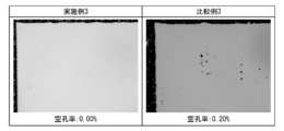
- the powder material M is an aluminum alloy
- the pores of the laminated model X are reduced and the mechanical properties are excellent. Therefore, the first gas component is preferably only one type of water.
- the powder material M is a titanium alloy
- the pores of the laminated model X are reduced and the mechanical properties are excellent. Therefore, the first gas component is a combination of three gas components of oxygen, water and nitrogen. Is preferable.
- the first purification tower 31 is a purification tower that removes oxygen from the shield gas as the first gas component.
- the first purification tower 31 is filled with an adsorbent capable of adsorbing oxygen, such as a nickel-based catalyst or a zinc-based catalyst.
- the adsorbent filled in the first purification tower 31 is preferably one capable of removing 99.99% or more of oxygen with respect to the concentration of oxygen in the gas introduced into the first purification tower 31. ..
- the first purification tower 31 is used when the quality of the laminated model can be expected to be improved by removing oxygen from the shield gas in the chamber 3 in consideration of the material of the powder material M.
- the first purification tower 31 is connected to the secondary end of the first supply line L1.
- An electromagnetic valve V4 is provided near the end on the secondary side of the first supply line L1.
- the solenoid valve V4 When the solenoid valve V4 is in the open state, a part of the shield gas in the chamber 3 is supplied to the first purification tower 31 via the first supply line L1. In this case, the first purification tower 31 removes oxygen as the first component from the shield gas supplied to the inside.
- the first connection line L5 connects the secondary end of the first refinery 31 with the primary end of the second refinery 32.
- An electromagnetic valve V5 is provided near the end on the primary side of the first connection line L5.
- the solenoid valve V5 When the solenoid valve V5 is in the open state, the first connection line L5 transfers the gas in the first purification tower 31 to the first purification tower 31 in the concentration adjusting unit 30 such as the second purification tower 32. It can be supplied to each configuration located on the next side.
- the concentration adjusting unit 30 the upstream side in the direction in which the gas in the chamber 3 flows to the second supply line L2 via the first supply line L1 and the connection lines L5 to L7 is set as the primary side.
- the downstream side is the secondary side.
- the first bypass line L8 connects the first supply line L1 on the primary side of the solenoid valve V4 and the first connection line L5 on the secondary side of the solenoid valve V5. Further, an electromagnetic valve V6 is provided on the first bypass line L8.
- the shield gas in the first supply line L1 is not supplied to the first purification tower 31, and the first bypass is performed.
- the shield gas can be supplied to the second purification tower 32 on the secondary side of the first purification tower 31 via the line L8.
- the concentration adjusting unit 30 supplies the shield gas in the first supply line L1 to the first purification tower 31. Then, the gas from which oxygen has been removed in the first purification tower 31 can be supplied to the second purification tower 32.
- the second purification tower 32 is a purification tower that removes water from the shield gas as the first gas component.
- the second purification tower 32 is filled with an adsorbent capable of adsorbing water, such as a mixture of a nickel-based catalyst and zeolite.
- the adsorbent filled in the second purification tower 32 is preferably one capable of removing 99.99% or more of the water content in the gas introduced into the second purification tower 32. ..
- the second purification tower 32 is used when the quality of the laminated model can be expected to be improved by removing water from the shield gas in the chamber 3 in consideration of the material of the powder material M.
- the second purification tower 32 is connected to the secondary end of the first connection line L5.
- An electromagnetic valve V7 is provided near the end on the secondary side of the first connection line L5.
- gas is supplied to the second purification tower 32 from the inside of the first connection line L5.
- the second purification tower 32 removes water as the first component from the shield gas supplied to the inside.
- the second connection line L6 connects the secondary end of the second refining tower 32 and the primary end of the third refining tower 33.
- An electromagnetic valve V8 is provided near the end on the primary side of the second connection line L6.
- the second bypass line L9 connects the first connection line L5 on the primary side of the solenoid valve V7 and the second connection line L6 on the secondary side of the solenoid valve V8. Further, an electromagnetic valve V9 is provided on the second bypass line L9.
- the shield gas in the first connection line L5 is not supplied to the second purification tower 32, and the second bypass is performed.
- the shield gas can be supplied to the third purification tower 33 on the secondary side of the second purification tower 32 via the line L9.
- the gas in the first connection line L5 can be supplied to the second purification tower 32, and the second purification tower can be supplied.
- the gas from which the water has been removed in 32 can be supplied to the third purification tower 33.
- the third purification tower 33 is a purification tower that removes nitrogen from the shield gas as the first gas component.
- the third purification tower 33 is filled with an adsorbent capable of adsorbing nitrogen such as silica gel.
- the adsorbent filled in the third purification tower 33 is preferably one capable of removing 99.99% or more of nitrogen with respect to the nitrogen concentration in the gas introduced into the third purification tower 33.
- the third purification tower 33 is used when the quality of the laminated model can be expected to be improved by removing nitrogen from the shield gas in the chamber 3 in consideration of the material of the powder material M.
- the third purification tower 33 is connected to the secondary end of the second connection line L6.
- An electromagnetic valve V10 is provided near the end on the secondary side of the second connection line L6.
- gas is supplied to the third purification tower 33 from the inside of the second connection line L6.
- the third purification tower 33 removes nitrogen as the first component from the shield gas supplied to the inside.
- the third connection line L7 connects the secondary end of the third refining tower 33 and the primary end of the fourth refining tower 34.
- An electromagnetic valve V11 is provided near the end on the primary side of the third connection line L7.
- the solenoid valve V11 When the solenoid valve V11 is in the open state, the gas in the third purification tower 33 is transferred to the third purification tower 33 in the concentration adjusting unit 30 such as the fourth purification tower 34 via the third connection line L7.
- it can be supplied to each configuration located on the secondary side.
- the third bypass line L10 connects the second connection line L6 on the primary side of the solenoid valve V10 and the third connection line L7 on the secondary side of the solenoid valve V11. Further, an electromagnetic valve V12 is provided on the third bypass line L10. When both the solenoid valves V10 and V11 are in the closed state and the solenoid valve V12 is in the open state, the shield gas in the second connection line L6 is not supplied to the third purification tower 33, and the third bypass is performed. It can be supplied to the fourth purification tower 34 on the secondary side of the third purification tower 33 via the line L10.
- the gas in the second connection line L6 can be supplied to the third purification tower 33, and the third purification tower can be supplied.
- the gas from which nitrogen has been removed in 33 can be supplied to the fourth purification tower 34.
- the fourth purification tower 34 is a purification tower that removes water from the shield gas as the first gas component and does not remove oxygen.
- the fourth purification tower 34 is filled with an adsorbent capable of adsorbing water such as zeolite and not adsorbing oxygen.
- the adsorbent filled in the fourth purification tower 34 is preferably one capable of removing 99.99% or more of the water content in the gas introduced into the fourth purification tower 34. ..
- the fourth purification tower 34 improves the quality of the laminated model by removing water from the shield gas in the chamber 3 and supplying oxygen as the second component in consideration of the material of the powder material M. Use when you can expect.
- the fourth purification tower 34 is connected to the secondary end of the third connection line L7.
- An electromagnetic valve V13 is provided near the end on the secondary side of the third connection line L7.
- gas is supplied to the fourth purification tower 34 from the inside of the third connection line L7.
- the fourth purification tower 34 removes water as the first component from the shield gas supplied to the inside. Since the fourth purification tower 34 is filled with an adsorbent that does not adsorb oxygen, the fourth purification tower 34 does not remove oxygen from the shield gas supplied to the inside.
- the secondary side end of the fourth refining tower 34 is connected to the primary side end of the second supply line L2.
- An electromagnetic valve V14 is provided near the end on the primary side of the second supply line L2.
- the fourth bypass line L11 connects the third connection line L7 on the primary side of the solenoid valve V13 and the second supply line L2 on the secondary side of the solenoid valve V14. Further, an electromagnetic valve V15 is provided on the fourth bypass line L11. When both the solenoid valves V13 and V14 are in the closed state and the solenoid valve V15 is in the open state, the shield gas in the third connection line L7 is introduced to the fourth purification tower 34 via the fourth bypass line L11. Can be supplied to the second supply line L2 on the secondary side of the fourth purification tower 34 without being supplied to.
- the gas in the third connection line L7 can be supplied to the fourth purification tower 34, and the fourth purification tower can be supplied.
- the gas from which only the water has been removed in 34 can be supplied to the second supply line L2.
- the supply unit of the concentration adjusting unit 30 supplies a second gas component selected according to the powder material M into the chamber 3 as needed.
- the CPU 37 determines whether or not the supply of the second gas component is executed, and if necessary, determines the gas type of the second gas component.
- the second gas component can be selected depending on, for example, the material of the powder material M.
- the second gas component examples include hydrogen, oxygen, carbon monoxide, carbon dioxide, ammonia, helium and the like.
- the second gas component may be a single type or a combination of a plurality of types of gas components.
- oxygen is preferable as the second gas component because the pores of the laminated model X are reduced and the mechanical properties can be expected to be improved.
- helium is preferable as the second gas component because an improvement in molding speed can be expected.
- the source 36 of the second gas component is one or more sources selected from the group consisting of hydrogen, oxygen, carbon monoxide, carbon dioxide, ammonia, and helium.
- the supply source 36 of the second gas component may have a plurality of supply sources according to the number of gas types of the second gas component, and the second gas component to be supplied may be included in the plurality of gas types. It may be in the form of having one supply source which can be selected and switched from.
- the form of the supply source 36 may be a PSA type gas generator or a gas cylinder.
- the supply source 36 includes a PSA type oxygen generator, an oxygen cylinder, and the like.
- the second gas component supply source 36 is connected to the second supply line L2 via the third supply line L12.
- the third supply line L12 supplies the gas in the second supply line L2 with the second gas component as needed.
- a solenoid valve V16 is provided on the third supply line L12. When the solenoid valve V16 is in the open state, the third supply line L12 can supply the second gas component selected by the supply source 36 to the gas in the second supply line L2.
- the supply unit of the concentration adjusting unit 30 having the configuration described above supplies the second gas component into the chamber 3 as needed via the third supply line L12 and the second supply line L2 in this order. To do.
- the filter unit 50 includes a filter 51 and a ventilator 52.
- the filter unit 50 takes out a part of the shield gas in the chamber 3 by the ventilator 52, and removes solid impurities such as fumes and spatters in the shield gas by the filter 51.
- solid impurities such as fumes and spatters in the shield gas in the chamber 3
- the quality of the laminated model X can be further improved.
- the laminated modeling system 70 described above includes a concentration adjusting unit 30.
- the concentration adjusting unit 30 has a purification unit that removes a first gas component, which is an impurity in the shield gas, according to the powder material. Therefore, the gas component that becomes an impurity in the shield gas is selected from the first purification tower, the second purification tower, the third purification tower, and the fourth purification tower according to the material of the powder material and the like. Can be removed. Therefore, the concentration of the gas component in the shield gas in the chamber, which is unnecessary for the production of the metal model, or the gas component which causes the deterioration of the mechanical properties of the metal model can be reduced depending on the powder material, and the powder can be reduced.
- the concentration adjusting unit 30 has a supply unit that supplies a second gas component selected according to the powder material into the chamber as needed. Therefore, the gas component expected to contribute to the quality improvement of the laminated model X can be supplied into the chamber according to the material of the powder material and the concentration thereof can be kept constant. As a result, the concentration of the second gas component in the shield gas in the chamber is optimized according to the powder material, and the quality of the metal model can be further improved according to the powder material.
- This laminated modeling system includes a concentration adjusting unit 30 and a circulation line L3, and the concentration adjusting unit 30 has a predetermined purification unit and a supply unit. Therefore, according to this laminated modeling system, a part of the shield gas in the chamber 3 can be taken out, the concentration of the shield gas can be adjusted by the concentration adjusting unit, and solid impurities such as fume and sputtering can be removed. As a result, the composition of the gas component in the shield gas in the chamber 3 can be reduced to the concentration (target value) optimized for improving the quality of the metal model in an extremely short time, and in the chamber 3 as needed. The concentration of the second gas component of the above can be adjusted to the target value, and the target value can be stably maintained.
- This laminated modeling system includes a concentration adjusting unit 30, a first supply line L1, and a second supply line L2. Therefore, when filling the chamber 3 with the shield gas, a part of the shield gas is taken out by the first supply line L1, oxygen is removed by the purification unit of the concentration adjusting unit 30, and then the second supply line L2. Oxygen can be purged from the inside of the chamber 3 while being resupplied into the chamber 3 by. As a result, the oxygen concentration can be reduced in an extremely short time and the consumption of the shield gas can be reduced as compared with the case where the oxygen in the chamber is purged only by supplying the shield gas. Therefore, it is possible to efficiently produce a laminated model with further improved quality in a shorter time than a conventional laminated modeling device.
- the concentration adjusting unit 30 and the filter unit 50 are configured separately from the laminated modeling unit 10. Therefore, by adding a configuration corresponding to the density adjustment unit 30 and the filter unit 50 to a generally commercially available 3D printer, the quality of various laminated models can be further improved.
- the laminated modeling method according to the present embodiment will be specifically described with reference to FIGS. 1 to 3.
- the main laminated molding method heat is supplied to the powder material using energy rays in the presence of a shield gas to form a layer.
- This is a laminated modeling method for producing a laminated model by sequentially laminating the layers.
- the present laminated modeling method will be described by taking the case of using the above-mentioned laminated modeling system 70 as an example, but the present invention is not limited to the following description.
- This laminated molding method has the following step (a) and step (b).
- This laminated molding method may further include the following step (c).
- step (a) and step (b) are performed in this laminated molding method.
- step (a) and step (b) may be performed in parallel.
- the composition of the gas component in the shield gas in the chamber 3 may change during the step (a), and the concentrations of the first gas component and the second gas component may fluctuate from the target values.
- step (a) is performed or the step (a) is stopped once, and then the step ( b) is started.
- the process can be started from step (b).
- the composition of the gas component in the shield gas in the chamber 3 may change during the step (b), and the concentrations of the first gas component and the second gas component may fluctuate from the target values.
- the powder material M when the powder material M is irradiated with the laser L during the step (a), a very small amount of water (liquid state) adhering to the surface of the powder material evaporates to become water vapor in the chamber 3.
- the water concentration may increase.
- the second purification tower 32 and, if necessary, the fourth purification tower 34 the water concentration in the chamber 3 is reduced.
- the presence of water in the chamber 3 is preferable for improving the quality of the metal model X in relation to the type of the powder material M, it is not necessary to reduce the water concentration in the chamber 3.
- Step (c) In an example of this laminated molding method, first, step (c) is carried out, and then step (b) is carried out.
- the inside of the chamber 3 may be opened to the atmosphere when the unused powder material M is supplied to the storage chamber 4 or when the laminated model is collected. At this time, since the oxygen concentration in the chamber 3 rises, step (c) is carried out. However, if the oxygen concentration in the chamber 3 is already sufficiently low, step (c) can be omitted.
- step (c) oxygen in the chamber 3 is purged (exhausted) from the inside of the chamber 3 by filling the chamber 3 with a shield gas before the irradiation of the laser L.
- the gas in the chamber 3 can be replaced with the shield gas, and the oxygen concentration in the chamber 3 can be reduced. Therefore, when the step (a) is carried out, the modeling layer is modeled and the modeling layer is laminated in an atmosphere in which the oxygen concentration is sufficiently reduced, the mechanical strength of the laminated model is improved, and the quality is improved. ..
- step (c) for example, the solenoid valves V1 and V2 shown in FIG.
- the shield gas is supplied from the shield gas supply line L4 into the chamber 3, and the purge line (not shown) is opened.
- the gas in the chamber 3 can be replaced with the shield gas, and the oxygen concentration in the chamber 3 can be reduced.
- step (c) and step (b) may be carried out in parallel.
- the solenoid valves V1, V2, and V3 shown in FIG. 1 are opened
- the solenoid valves V4 and V5 shown in FIG. 3 are opened
- the shield gas is supplied into the chamber 3 from the shield gas supply line L4. Open the purge line of.
- oxygen can be removed in the first purification tower 31 while replacing the gas in the chamber 3 with the shield gas, so that the oxygen concentration in the chamber 3 can be reduced in a short time.
- Step (c) and step (b) may be carried out in parallel while removing the first gas component other than oxygen in the same manner.
- Step (a) As shown in FIG. 2, in step (a), the powder material M in the chamber 3 is irradiated with a laser L as an energy ray, a modeling layer is formed in the chamber 3, and the shaped modeling layers are sequentially laminated.
- the implementation of step (a) may be started when the composition of the gas component in the shield gas in the chamber 3 is sufficiently optimized to enhance the quality of the laminated structure according to the powder material M. ..
- step (a) the laminated modeling unit 10 is used to repeat the modeling and laminating of the modeling layer on the modeling stage 9 in the chamber 3.
- a state in which the powder material M on the upper side of the modeling stage 9 is irradiated with the laser L to form one modeling layer will be described as an example.
- the modeling stage 9 usually moves downward.
- the new powder material M is supplied and spread on the upper side of one molding layer by the recorder 7 from the storage stage 8. In this state, when a new modeling layer is further formed by irradiating the laser L, a new modeling layer is provided on the upper side of one already modeled modeling layer.
- step (a) the modeling stage 9 moves further downward, and a new powder material M is further supplied from above the storage stage 8. Then, when the laser L is further irradiated, a new modeling layer is further provided on the upper side of the already laminated modeling layer. In this way, in step (a), the modeling layer is sequentially modeled and the modeling layer is laminated on the modeling stage 9.
- step (a) in the laminated modeling unit 10, when the irradiation of the laser L based on the data input in advance is completed and the laminated model X is completed, the laminated model X is collected.
- the modeling stage 9 rises to the same height as the bottom surface B of the chamber 3, and the powder material after modeling the modeling layer is conveyed to the collection chamber 6 by the recorder 7.
- the used powder material recovered in the recovery chamber 6 may be reused after being subjected to a treatment such as reduction.
- step (b) In step (b), the first gas component which is an impurity in the shield gas in the chamber 3 is removed according to the powder material M, and the second gas component selected according to the powder material M is required. It is supplied into the chamber 3 according to the above. Implementation of step (b) may be initiated when the composition of the gas component in the shield gas in the chamber 3 is not optimized to enhance the quality of the laminate.
- step (b) at least one or more gas components selected from the group consisting of oxygen, water and nitrogen can be removed from the shield gas in the chamber 3 as the first gas component.
- gas components selected from the group consisting of oxygen, water and nitrogen can be removed from the shield gas in the chamber 3.
- the CPU 37 determines the gas type of the first gas component in the purification unit based on information (external signal) such as the material of the powder material M.
- step (b) for example, considering the material of the powder material M, the first densitometer C1 and the second densitometer C2 are transmitted from the first densitometer C1 and the second densitometer C2 based on the oxygen concentration and the water concentration in the chamber 3.
- the gas component of 1 may be determined.
- Examples of the first gas component include the following (X1) to (X7).
- These combinations (X1) to (X7) are assumed based on the configuration of the purification tower of the concentration adjusting unit 30, and the first gas component in the present invention is not limited to these combinations.
- the first gas component can be appropriately changed by changing the number of purification towers and the adsorbent in each purification tower, and in addition to these exemplified gas components, Other gas components may be removed as the first gas component.
- the first gas component can be switched according to the type of the powder material M.
- the first purification tower 31 is used in the concentration adjusting unit 30 shown in FIG. Specifically, the solenoid valves V4, V5, V9, V12, and V15 are opened, and the solenoid valves V6, V7, V8, V10, V11, V13, and V14 are closed. As a result, oxygen can be removed from the shield gas in the chamber 3 as the first gas component by the first purification tower 31.
- the second purification tower 32 is used in the concentration adjusting unit 30 shown in FIG.
- the solenoid valves V6, V7, V8, V12, and V15 are opened, and the solenoid valves V4, V5, V9, V10, V11, V13, and V14 are closed.
- the first gas component is the above (X3)
- the third purification tower 33 is used in the concentration adjusting unit 30 shown in FIG.
- the solenoid valves V6, V9, V10, V11, and V15 are opened, and the solenoid valves V4, V5, V7, V8, V12, V13, and V14 are closed.
- the first purification tower 31 and the second purification tower 32 are used in combination in the concentration adjusting unit 30 shown in FIG. Specifically, the solenoid valves V4, V5, V7, V8, V12, and V15 are opened, and the solenoid valves V6, V9, V10, V11, V13, and V14 are closed. As a result, oxygen and water as the first gas component can be removed from the shield gas in the chamber 3 by the first purification tower 31 and the second purification tower 32, respectively.
- the second purification tower 32 and the third purification tower 33 are used in combination in the concentration adjusting unit 30 shown in FIG. Specifically, the solenoid valves V6, V7, V8, V10, V11, and V15 are opened, and the solenoid valves V4, V5, V9, V12, V13, and V14 are closed. As a result, water and nitrogen can be removed from the shield gas in the chamber 3 as the first gas component by the second purification tower 32 and the third purification tower 33, respectively.
- the first gas component is the above (X6)
- the first purification tower 31 and the third purification tower 33 are used in combination in the concentration adjusting unit 30 shown in FIG.
- the solenoid valves V4, V5, V9, V10, V11, and V15 are opened, and the solenoid valves V6, V7, V8, V12, V13, and V14 are closed.
- nitrogen and oxygen as the first gas component can be removed from the shield gas in the chamber 3 by the first purification tower 31 and the third purification tower 33, respectively.
- the first gas component is the above (X7), in the concentration adjusting unit 30 shown in FIG. 3, the first purification tower 31, the second purification tower 32, and the third purification tower 33 are combined. To use.
- the solenoid valves V4, V5, V7, V8, V10, V11, and V15 are opened, and the solenoid valves V6, V9, V12, V13, and V14 are closed.
- the first gas component is the above (X7)
- the concentration adjusting unit 30 shown in FIG. 3 the first purification tower 31, the second purification tower 32, and the third purification tower 33
- the solenoid valves V4, V5, V7, V8, V10, V11, V13, and V14 are opened, and the solenoid valves V6, V9, V12, and V15 are closed.
- oxygen, water, and nitrogen can be removed from the shield gas in the chamber 3 as the first gas components by the first purification tower 31, the second purification tower 32, and the third purification tower 33, respectively. ..
- step (b) according to the present laminated molding method, one or more gas components selected from the group consisting of hydrogen, oxygen, carbon monoxide, carbon dioxide, and ammonia can be supplied into the chamber 3 into the chamber 3.
- the CPU 37 determines whether or not to supply the second gas component based on information (external signal) such as the material of the powder material M, and determines whether or not the second gas component is supplied. Determine the gas type of.
- step (b) for example, when the material of the powder material M is taken into consideration and it can be expected that the quality of the laminated model X can be improved by supplying the second gas component, the second gas It is decided to supply the component to the second supply line L2, and the gas type of the second gas component is determined according to the powder material M.
- the determination of the execution of the supply of the second gas component and the type of the second gas component can be determined according to the material of the powder material M. Further, in addition to the information regarding the powder material M, the gas type of the first gas component determined according to the powder material M, the chamber 3 measured by the first densitometer C1 and the second densitometer C2. It can also be determined according to the oxygen concentration and hydrogen concentration in the chamber. For example, when the powder material M is an aluminum alloy, the pores in the cross section of the metal model are reduced, and the quality of the metal model can be further improved. Therefore, oxygen is used as the second gas component in the chamber 3. It is preferable to supply the inside.
- the CPU 37 determines the supply of the second gas component, and the solenoid valve V16 is opened. In addition, the CPU 37 determines the gas type of the second gas component as oxygen, and selects the oxygen supply source as the supply source 36.
- the fourth purification tower 34 When oxygen is supplied into the chamber 3 as the second gas component as in the case where the powder material M is an aluminum alloy, it is preferable to use the fourth purification tower 34.
- the first purification tower 31 when the oxygen concentration in the chamber 3 transmitted from the first densitometer C1 is lower than the target concentration for optimization, the first purification tower 31 is not used and the second purification tower 32, A third purification tower 33 and a fourth purification tower 34 may be used.
- the valves V6, V7, V8, V10, V11, V13, and V14 are opened, and the valves V4, V5, V9, V12, and V15 are closed.
- the valves V6, V9, V12, V13, and V14 are opened, and the valves V4, V5, V7, V8, V10, V11, and V15 are closed.
- the first refining tower 31, the second refining tower 32, and the third refining tower 33 may not be used, and only the fourth refining tower 34 may be used.
- the valves V6, V9, V12, V13, and V14 are opened, and the valves V4, V5, V7, V8, V10, V11, and V15 are closed.
- the second gas component can be supplied to the gas from which the first gas component has been removed by the purification unit of the concentration adjusting unit 30 as needed. Therefore, the concentration of the second gas component in the chamber 3 can be kept constant, and the quality of the laminated model can be further improved according to the powder material M.
- step (c) when oxygen is supplied into the chamber 3 as a second gas component as in the case where the powder material M is an aluminum alloy, in step (c), the first purification tower 31 and the second purification tower are used. It is also envisioned that 32 is used to remove both oxygen and water in the chamber 3, followed by steps (a) and (b) at the same time. In this case, since it is assumed that the water concentration in the chamber 3 increases in the step (a), the water is removed from the shield gas in the second purification tower 32 by carrying out the step (b). Further, when the powder material M is an aluminum alloy, the pores in the cross section of the metal model are reduced, and the quality of the metal model can be further improved. Therefore, in step (b), oxygen is supplied from the supply source 36. Is supplied into the chamber 3.
- step (c) oxygen and water are removed from the first purification towers 31 and the second. Purging from the chamber 3 while removing in the purification tower 32, and in step (b), the combination of two gas components, oxygen and water, can be removed as the first gas component. preferable.
- step (c) when the powder material M is a titanium alloy, the pores of the laminated model X are reduced and the mechanical properties are excellent. Therefore, in step (c), three types of gas components, oxygen, moisture, and nitrogen, are used.
- step (b) Purging these three gas components from the chamber 3 while removing them in the first purification tower 31, the second purification tower 32, and the third purification tower 33, and in step (b), these three types. It is preferable to remove the gas component of the above as the first gas component.
- the selection of the first gas component and / or the second gas component in step (b) is performed according to the powder material M. The quality of the metal model can be further improved.
- the filter unit 50 shown in FIG. 1 may be used to remove solid impurities such as fumes and sputtering in the shield gas with the filter 51.
- solid impurities such as fumes and sputtering may occur during the modeling and laminating of the modeling layer. Therefore, these solid impurities such as fumes and spatters can further improve the quality of the laminated model X.
- step (b) The present laminated modeling method described above has step (b).
- the first gas component which is an impurity in the shield gas
- the gas component that becomes an impurity in the shield gas is selected from the first purification tower, the second purification tower, the third purification tower, and the fourth purification tower according to the material of the powder material and the like. Can be removed. Therefore, it is possible to reduce the concentration of the gas component in the shield gas in the chamber, which is unnecessary for the production of the metal model, and the gas component which causes the deterioration of the mechanical properties of the metal model, depending on the powder material. The quality of the gas can be further enhanced depending on the powder material.
- step (b) according to the present laminated molding method a second gas component selected according to the powder material is supplied into the chamber as needed. Therefore, the gas component expected to contribute to the quality improvement of the laminated model X can be supplied into the chamber according to the material of the powder material and the concentration thereof can be kept constant. As a result, the concentration of the second gas component in the shield gas in the chamber is optimized according to the powder material, and the quality of the metal model can be further improved according to the powder material.
- the concentration of the shield gas in the chamber 3 can be adjusted by the concentration adjusting unit, and solid impurities such as fume and sputtering can be removed.
- the composition of the gas component in the shield gas in the chamber 3 can be reduced to the concentration (target value) optimized for improving the quality of the metal model in an extremely short time, and in the chamber 3 as needed.
- the concentration of the second gas component of the above can be adjusted to the target value, and the target value can be stably maintained.
- the oxygen concentration and the water concentration in the shield gas in the chamber 3 can be reduced to an extremely low concentration for a short time. Can be adjusted with. Then, if necessary, oxygen is supplied as a second gas component from the supply source 36 to the chamber 3 via the third supply line L12 and the second supply line L2 to optimize the oxygen concentration. It can be adjusted to the adjusted concentration and the optimized component composition can be maintained.
- the oxygen concentration can be reduced in an extremely short time and the consumption of the shield gas can be reduced as compared with the case where the oxygen in the chamber is purged only by supplying the shield gas. Therefore, it is possible to efficiently produce a laminated model with further improved quality in a short time as compared with the conventional laminated modeling method.
- step (c) a part of the shield gas in the chamber 3 can be taken out by the first supply line L1 and oxygen can be removed from the shield gas by the first purification tower 31. It can then be resupplied into chamber 3 via the second supply line L2.
- the oxygen concentration in the shield gas in the chamber 3 can be shortened in a short time. Can be reduced.
- the shield gas is newly supplied into the chamber 3 by the shield gas supply line L4. You don't have to.
- the oxygen concentration can be reduced to a low level that could not be achieved unless a large amount of shield gas is conventionally supplied into the chamber 3 with a relatively small amount of shield gas supplied. .. Further, since the supply amount of the shield gas is significantly reduced, the oxygen concentration in the chamber 3 can be reduced in an extremely short time.
- the present invention is not limited to such specific embodiments.
- the present invention may be added, omitted, replaced, or otherwise modified within the scope of the gist of the present invention described in the claims.
- the number of purification towers is four, but the present invention is not limited to the embodiment in which the number of purification towers is four.
- the number of purification towers can be changed according to the number of first gas components to be removed.
- the purification unit removes at least one or more gas components selected from the group consisting of oxygen, water, and nitrogen.
- the first gas component to be removed may further contain other gas components in addition to these oxygen, water, and nitrogen. Therefore, in another embodiment, the number of adsorbents and purification towers in the purification tower can be changed according to the powder material M.
- the control unit of the concentration adjustment unit has been described as a configuration separate from the purification unit and the supply unit of the concentration adjustment unit. However, the control unit may be included in each configuration of the purification unit and the supply unit. Further, in the above-described embodiment, the control unit is disclosed as a configuration of the concentration adjusting unit, but in other embodiments, the control unit may be configured as a laminated molding unit, and the laminated molding unit and the concentration may be used. It may be configured as a laminated molding system separate from the adjustment unit.
- step (c) was performed for 2 hours. Specifically, the solenoid valves V3 were opened, the solenoid valves V1 and V2 were closed, and the purge line (not shown) was opened to replace the gas in the chamber 3 with the shield gas.
- the valves V1 and V2 are opened, the solenoid valve V3 is closed, the execution of step (c) is completed, and the shield gas by the purge line (not shown) is used. The supply was stopped. Then, the implementation of step (b) was started.
- step (b) the solenoid valves V4, V5, V9, V12, and V15 shown in FIG.
- step (c) When 2 hours have passed since the start of step (c), the solenoid valves V6, V7, V8, V12, and V15 are opened, and the solenoid valves V4, V5, V9, V10, V11, V13, and V14 are closed. Except for removing water in the second purification tower 32, the implementation of step (c) was completed in the same manner as in Example 1, the supply of the shield gas by the purge line (not shown) was stopped, and the implementation of step (b) was performed. Started. Then, in order to verify the effect of carrying out step (b), the time course of the measured value of the water concentration in the chamber 3 was observed.
- Example 3 In the laminated modeling system 70, a titanium alloy was used as the powder material. In Example 3, it was determined by the CPU 37 that the combination of three types of gas components (X7): oxygen, water, and nitrogen was removed as the first gas component in step (b). Further, the CPU 37 has determined that the supply source 36 does not supply the second gas component. First, the solenoid valves V3 are opened, the solenoid valves V1 and V2 are closed, and the purge line (not shown) is opened to replace the gas in the chamber 3 with a shield gas, and step (c) is performed for 2 hours. went.
- X7 oxygen, water, and nitrogen
- step (c) When 2 hours have passed since the start of step (c), the solenoid valves V4, V5, V7, V8, V10, V11, and V15 are opened, and the solenoid valves V6, V9, V12, V13, V14, and V16 are closed. Then, the supply of shield gas by the purge line (not shown) was stopped. After that, oxygen, water, and nitrogen are removed from the shield gas in the chamber 3 as the first gas components by the first purification tower 31, the second purification tower 32, and the third purification tower 33 (the step (). While carrying out b), step (a) was carried out to produce a laminated model made of a stainless alloy.
- Example 4 In the laminated modeling system 70, an aluminum alloy was used as the powder material. In Example 4, it was determined by the CPU 37 that one type of gas component of X (2): water was removed as the first gas component in step (b). Further, the CPU 37 determines that oxygen is supplied from the supply source 36. First, the solenoid valves V3 are opened, the solenoid valves V1 and V2 are closed, and the purge line (not shown) is opened to replace the gas in the chamber 3 with a shield gas, and step (c) is performed for 2 hours. went.
- step (c) When 2 hours have passed since the start of step (c), the solenoid valves V6, V7, V8, V12, V13, V14, and V16 are opened, and the solenoid valves V4, V5, V9, V10, V11, and V15 are closed. Then, the supply of shield gas by the purge line (not shown) was stopped. After that, only water is removed from the shield gas in the chamber 3 as the first gas component by the second purification tower 32 and the fourth purification tower 34, and oxygen is added from the supply source 36 as the second gas component. While performing the step (b) of supplying into the chamber 3, the step (a) was carried out to manufacture a laminated model made of a stainless alloy.
- FIG. 4 is a graph showing a time lapse of the oxygen concentration in the chamber in Example 1 and a time lapse of the oxygen concentration in the chamber in Comparative Example 1.
- the oxygen concentration in the chamber 3 was sharper than that in Comparative Example 1. Decreased to. From this result, it was confirmed that the oxygen concentration in the chamber 3 can be reduced to a low level (about 1 ppm) in an extremely short time according to the laminated modeling system 70. As described above, in Example 1, the oxygen concentration in the chamber 3 could be reduced to a low level even if the amount of the shield gas used for purging was relatively small. Therefore, it is considered that a laminated model with less oxygen atoms mixed in, excellent mechanical properties, and high quality laminated model can be produced efficiently in a short time and at low cost.
- FIG. 5 is a graph showing a comparison between the passage of time of the water concentration in the chamber in Example 2 and the water concentration in the chamber in Comparative Example 2.
- the water concentration in the chamber 3 was sharper than that in Comparative Example 2. Decreased to. From this result, it was confirmed that according to the laminated modeling system 70, the water concentration in the chamber 3 can be reduced to a low level (about 5 ppm) in an extremely short time.
- the water concentration in the chamber 3 could be reduced to a low level. Therefore, it is considered that a laminated model with hydrogen atoms is less likely to be mixed, mechanical properties are excellent, and a high-quality laminated model can be produced efficiently and at low cost in a short time.
- FIG. 6 is a diagram showing a comparison between an enlarged photograph of a cross section of a metal model made of a titanium alloy of Example 3 and an enlarged photograph of a cross section of a metal model made of a titanium alloy of Comparative Example 3.
- the pore ratio of the laminated model of Example 3 was 0.00%, whereas that of the laminated model of Comparative Example 3 was 0.20%. In this way, by adjusting the composition of the gas component in the chamber 3 according to the material of the powder material M, it was possible to reduce the vacancies of the laminated model and further improve the quality.
- FIG. 7 is a diagram showing an enlarged photograph of a cross section of a metal model made of an aluminum alloy of Example 4 in comparison with an enlarged photograph of a cross section of a metal model made of an aluminum alloy of Comparative Example 4.
- the pore ratio of the laminated model of Comparative Example 4 was 0.12%, whereas that of the laminated model of Comparative Example 4 was 0.20%. In this way, by adjusting the composition of the gas component in the chamber 3 according to the material of the powder material M, it was possible to reduce the vacancies of the laminated model and further improve the quality.
Landscapes
- Engineering & Computer Science (AREA)
- Chemical & Material Sciences (AREA)
- Materials Engineering (AREA)
- Manufacturing & Machinery (AREA)
- Physics & Mathematics (AREA)
- Optics & Photonics (AREA)
- Plasma & Fusion (AREA)
- Health & Medical Sciences (AREA)
- Toxicology (AREA)
- Mechanical Engineering (AREA)
- Automation & Control Theory (AREA)
- General Health & Medical Sciences (AREA)
- Sustainable Development (AREA)
- Life Sciences & Earth Sciences (AREA)
- Environmental & Geological Engineering (AREA)
- Powder Metallurgy (AREA)
- Welding Or Cutting Using Electron Beams (AREA)
- Laser Beam Processing (AREA)
Abstract
本発明は、積層造形物の品質のさらなる向上が可能となる、積層造形システムを提供することを目的とし、シールドガスの存在下で、エネルギー線を用いて粉体材料に熱を供給して層を造形し、造形した層を順次積層する積層造形ユニット(10)と、シールドガス中のガス成分の濃度を調整する濃度調整ユニット(30)とを備え、積層造形ユニット(10)は、粉体材料に照射するエネルギー線の照射源を含む照射部と、シールドガスが充填されるチャンバー、および層の造形および積層が行われる造形ステージを含む造形部とを有し、濃度調整ユニット(30)は、シールドガス中の不純物となる第1のガス成分を、粉体材料に応じて除去する精製部と、粉体材料に応じて選択される第2のガス成分を必要に応じてチャンバー内に供給する供給部とを有する積層造形システム(70)を提供する。
Description
本発明は、積層造形システム、積層造形方法に関する。
Additive Manufacturingと称される付加製造技術がある。付加製造技術の一例として、樹脂、金属等の粉体材料を任意の形状の層に造形し、造形した層を順次積層して任意の形状の積層造形物を作製する積層造形装置が知られている。
付加製造技術による積層造形装置の一例として、造形ステージ上の金属粉体をレーザー等で焼結する金属3Dプリンターが知られている。金属3Dプリンターは、焼結した金属層を造形ステージ上で順次積層し、複雑な形状の構造物を短時間で精度よく製造できる。そのため、金属3Dプリンターは、航空機産業および医療等の先端技術分野で有望な技術として注目されている(例えば、特許文献1)。
付加製造技術による積層造形装置の一例として、造形ステージ上の金属粉体をレーザー等で焼結する金属3Dプリンターが知られている。金属3Dプリンターは、焼結した金属層を造形ステージ上で順次積層し、複雑な形状の構造物を短時間で精度よく製造できる。そのため、金属3Dプリンターは、航空機産業および医療等の先端技術分野で有望な技術として注目されている(例えば、特許文献1)。
特許文献1に記載の積層造形装置は、不活性ガスで充満される造形室と、粉体材料層の所定箇所にレーザー光を照射して粉体材料を焼結させて焼結体を形成するレーザー光照射部とを備える。特許文献1に記載の積層造形装置等の従来の金属3Dプリンターにおいては、レーザー光のパラメータおよび特性、金属層の厚さ等を制御することで、品質向上を図ることが一般的である。
積層造形装置には、積層造形物の品質のさらなる向上が求められている。品質向上のためには焼結等の対象となる金属粉体の材質に応じて、造形室内の雰囲気中のガス成分の濃度を最適化し、最適化した濃度を一定に保持することが望ましい。
しかし、特許文献1に記載の積層造形装置にあっては、金属粉体の材質に応じて造形室内の雰囲気中のガス成分の濃度を最適化する機能がない。加えて、金属粉体の材質に応じて造形室内のガス成分の濃度を一定に保持する機能もない。そのため、特許文献1に記載の積層造形装置では、使用する粉体材料に応じて積層造形物の品質をさらに高めることができない。
しかし、特許文献1に記載の積層造形装置にあっては、金属粉体の材質に応じて造形室内の雰囲気中のガス成分の濃度を最適化する機能がない。加えて、金属粉体の材質に応じて造形室内のガス成分の濃度を一定に保持する機能もない。そのため、特許文献1に記載の積層造形装置では、使用する粉体材料に応じて積層造形物の品質をさらに高めることができない。
本発明は、積層造形物の品質のさらなる向上が可能となる、積層造形システムを提供する。
本発明は以下の積層造形システムを提供する。
[1] シールドガスの存在下で、エネルギー線を用いて粉体材料に熱を供給して層を造形し、前記層を順次積層して積層造形物を製造する積層造形システムであって、
上記積層造形システムは、前記層を造形し、前記層を順次積層する積層造形ユニットと、前記シールドガス中のガス成分の濃度を調整する濃度調整ユニットとを備え、
前記積層造形ユニットは、前記粉体材料に照射するエネルギー線の照射源を含む照射部と、前記シールドガスが充填されるチャンバー、および前記層の造形および積層が行われる造形ステージを含む造形部とを有し、
前記濃度調整ユニットは、前記シールドガス中の不純物となる第1のガス成分を、前記粉体材料に応じて除去する精製部と、前記粉体材料に応じて選択される第2のガス成分を必要に応じて前記チャンバー内に供給する供給部とを有する。
[2] 前記チャンバー内の前記シールドガスの一部を前記精製部に供給する第1の供給ラインをさらに備え、
前記精製部が、前記第1の供給ラインと接続される、下記の第1の精製塔、第2の精製塔、第3の精製塔および第4の精製塔からなる群から選ばれる少なくとも一つ以上を含む、[1]に記載の積層造形システム。
第1の精製塔:前記シールドガスから酸素を除去する精製塔
第2の精製塔:前記シールドガスから水分を除去する精製塔
第3の精製塔:前記シールドガスから窒素を除去する精製塔
第4の精製塔:前記シールドガスから水分を除去し、酸素を除去しない精製塔
[3] 前記精製部が、下記の第1のバイパスライン、第2のバイパスライン、第3のバイパスラインおよび第4のバイパスラインからなる群から選ばれる少なくとも一つ以上をさらに含む、[2]に記載の積層造形システム。
第1のバイパスライン:前記第1の供給ラインから供給される前記シールドガスを、前記第1の精製塔に供給せずに前記第1の精製塔の二次側に供給するバイパスライン
第2のバイパスライン:前記第1の供給ラインから供給される前記シールドガスを、前記第2の精製塔に供給せずに前記第2の精製塔の二次側に供給するバイパスライン
第3のバイパスライン:前記第1の供給ラインから供給される前記シールドガスを、前記第3の精製塔に供給せずに前記第3の精製塔の二次側に供給するバイパスライン
第4のバイパスライン:前記第1の供給ラインから供給される前記シールドガスを、前記第4の精製塔に供給せずに前記第4の精製塔の二次側に供給するバイパスライン
[4] 前記供給部が、水素、酸素、一酸化炭素、二酸化炭素、およびアンモニアからなる群から選ばれる一つ以上の前記第2のガス成分の供給源を含む、[1]~[3]のいずれかに記載の積層造形システム。
[5] 前記精製部によって前記シールドガスから前記第1のガス成分が除去されたガスを、前記チャンバーに供給する第2の供給ラインをさらに備え、前記供給部が、前記第2の供給ライン中の前記ガスに前記第2のガス成分を必要に応じて供給する第3の供給ラインをさらに含む、[1]~[4]のいずれかに記載の積層造形システム。
[6] シールドガスの存在下で、エネルギー線を用いて粉体材料に熱を供給して層を造形し、前記層を順次積層して積層造形物を製造する積層造形方法であって、
前記層を造形し、前記層を順次積層するステップ(a)と、前記シールドガス中のガス成分の濃度を調整するステップ(b)とを有し、
前記ステップ(a)では、チャンバー内の粉体材料にエネルギー線を照射し、前記チャンバー内で前記層を造形し、造形した前記層を順次積層し、
前記ステップ(b)では、前記シールドガス中の不純物となる第1のガス成分を、前記粉体材料に応じて除去し、前記粉体材料に応じて選択される第2のガス成分を必要に応じて前記チャンバー内に供給する、積層造形方法。
[7] 前記ステップ(b)で、酸素、水分、および窒素からなる群から選ばれる少なくとも一つ以上のガス成分を前記第1のガス成分として前記シールドガスから除去する、[6]に記載の積層造形方法。
[8] 前記ステップ(b)で、水素、酸素、一酸化炭素、二酸化炭素、およびアンモニアからなる群から選ばれる一つ以上のガス成分を前記第2のガス成分として前記チャンバー内に供給する、[6]又は[7]に記載の積層造形方法。
[9] 前記ステップ(b)で、前記粉体材料の種類に応じて前記第1のガス成分を切り替える、[6]~[8]のいずれかに記載の積層造形方法。
[10] 前記ステップ(b)で、前記第1のガス成分が除去されたガスに前記第2のガス成分を必要に応じて供給する、[6]~[9]のいずれかに記載の積層造形方法。
本発明によれば、積層造形物の品質のさらなる向上が可能となる、積層造形システムが提供される。
<積層造形システム>
本実施形態に係る積層造形システム(以下「本積層造形システム」と記載する。)は、シールドガスの存在下で、エネルギー線を用いて粉体材料に熱を供給して層を造形し、層を順次積層して積層造形物を製造するシステムである。本積層造形システムは、積層造形ユニットと濃度調整ユニッとを備える。
本実施形態に係る積層造形システム(以下「本積層造形システム」と記載する。)は、シールドガスの存在下で、エネルギー線を用いて粉体材料に熱を供給して層を造形し、層を順次積層して積層造形物を製造するシステムである。本積層造形システムは、積層造形ユニットと濃度調整ユニッとを備える。
積層造形ユニットは、シールドガスの存在下で、エネルギー線を用いて粉体材料に熱を供給して層を造形し、層を順次積層する。
積層造形ユニットは、粉体材料に照射するエネルギー線の照射源を含む照射部と、チャンバーおよび造形ステージを含む造形部とを有する。チャンバーにはシールドガスが充填される。シールドガスは、エネルギー線の照射の際に、粉体材料周囲の雰囲気における酸素濃度を低減するための不活性ガスである。
本積層造形システムにおいて、エネルギー線は特に限定されない。例えば、レーザー、電子ビーム等が挙げられる。そして、造形ステージでは、エネルギー線による層の造形、および造形した層の積層が行われる。
積層造形ユニットは、粉体材料に照射するエネルギー線の照射源を含む照射部と、チャンバーおよび造形ステージを含む造形部とを有する。チャンバーにはシールドガスが充填される。シールドガスは、エネルギー線の照射の際に、粉体材料周囲の雰囲気における酸素濃度を低減するための不活性ガスである。
本積層造形システムにおいて、エネルギー線は特に限定されない。例えば、レーザー、電子ビーム等が挙げられる。そして、造形ステージでは、エネルギー線による層の造形、および造形した層の積層が行われる。
濃度調整ユニットはシールドガス中のガス成分の濃度を調整する。濃度調整ユニットは、精製部と供給部とを有する。精製部は、シールドガス中の不純物となる第1のガス成分を、粉体材料に応じて除去する。供給部は、粉体材料に応じて選択される第2のガス成分を必要に応じてチャンバー内に供給する。
以下、一実施形態例について図面を参照しながら詳細に説明する。ただし、以下の説明で用いる図面は、特徴をわかりやすくするために、便宜上特徴となる部分を拡大して示している場合があり、各構成要素の寸法比率などが実際と同じであるとは限らない。
図1は、本積層造形システムの構成の一例を示す模式図である。図1に示す積層造形システム70は、積層造形ユニット10と、濃度調整ユニット30と、フィルターユニット50と、第1の供給ラインL1と、第2の供給ラインL2と、循環ラインL3と、電磁バルブV1~V3とを備える。積層造形システム70は、シールドガスの存在下で、エネルギー線を用いて粉体材料に熱を供給して層を造形し、層を順次積層して積層造形物を製造するシステムである。
積層造形ユニット10は、シールドガスの存在下でエネルギー線を用いて粉体材料に熱を供給して層を造形し、造形した層を順次積層する。濃度調整ユニット30は、シールドガス中のガス成分の濃度を調整する。フィルターユニット50は、シールドガス中のフューム、スパッタ等の固体の不純物を除去する。
積層造形ユニット10は、シールドガスの存在下でエネルギー線を用いて粉体材料に熱を供給して層を造形し、造形した層を順次積層する。濃度調整ユニット30は、シールドガス中のガス成分の濃度を調整する。フィルターユニット50は、シールドガス中のフューム、スパッタ等の固体の不純物を除去する。
第1の供給ラインL1は、上記積層造形ユニット10が具備するチャンバー3(詳細は後述する)内のシールドガスの一部を濃度調整ユニット30の精製部に供給する。第1の供給ラインL1は、チャンバー3と、後述の第1の精製塔31とを接続する。第1の供給ラインL1には電磁バルブV1が設けられている。電磁バルブV1が開状態であるとき、第1の供給ラインL1は、チャンバー3内のシールドガスを濃度調整ユニット30の精製部に供給する。
第2の供給ラインL2は、濃度調整ユニット30の精製部によってシールドガスから第1のガス成分が除去されたガスを、チャンバー3内に供給する。第2の供給ラインL2は、後述の第4の精製塔34と、チャンバー3とを接続する。第2の供給ラインL2には電磁バルブV2が設けられている。電磁バルブV2が開状態であるとき、第2の供給ラインL2は、濃度調整ユニット30の精製部によってシールドガスからシールドガス中の不純物となる第1のガス成分が除去されたガスをチャンバー3内に供給する。
循環ラインL3は、電磁バルブV1の一次側の第1の供給ラインL1と、電磁バルブV2の二次側の第2の供給ラインL2とを接続する。ここで、第1の供給ラインL1中のガスが積層造形ユニット10から濃度調整ユニット30に流れる方向の上流側を一次側とし、下流側を二次側とする。また、第2の供給ラインL2中のガスが濃度調整ユニット30から積層造形ユニット10に流れる方向の上流側を一次側とし、下流側を二次側とする。
循環ラインL3には電磁バルブV3が設けられている。電磁バルブV3が開状態であり、電磁バルブV1、V2がいずれも閉状態であるとき、積層造形システム70は、チャンバー3内のシールドガスの一部を第1の供給ラインL1内に導入し、第1の供給ラインL1内のシールドガスを循環ラインL3、第2の供給ラインL2をこの順に経由させてチャンバー3内に再度供給する。
電磁バルブV1、V2、V3がいずれも開状態であるとき、積層造形システム70は、チャンバー3内のシールドガスの一部を第1の供給ラインL1内に導入し、次いで、濃度調整ユニット30に供給し、残部のシールドガスを第2の供給ラインL2を経由させてチャンバー3内に再度供給する。
積層造形システム70においては、電磁バルブV1~V3は後述のCPU37と電気的に接続されている。各電磁バルブの開閉状態は、CPU37によって制御可能である。
電磁バルブV1、V2、V3がいずれも開状態であるとき、積層造形システム70は、チャンバー3内のシールドガスの一部を第1の供給ラインL1内に導入し、次いで、濃度調整ユニット30に供給し、残部のシールドガスを第2の供給ラインL2を経由させてチャンバー3内に再度供給する。
積層造形システム70においては、電磁バルブV1~V3は後述のCPU37と電気的に接続されている。各電磁バルブの開閉状態は、CPU37によって制御可能である。
図2は、積層造形システム70が備える積層造形ユニット10の構成を示す模式図である。図2に示すように積層造形ユニット10は、レーザー発振器1と、光学系2と、チャンバー3と、貯蔵室4と、造形室5と、回収室6と、リコーター7と、貯蔵ステージ8と、造形ステージ9と、第1の濃度計C1と、第2の濃度計C2とを含む。積層造形ユニット10は、レーザー発振器1を用いてレーザーL(エネルギー線の一例)の照射により造形ステージ9上の粉体材料Mに熱を供給して層を造形し、造形した層を順次積層し、積層造形物Xとする。
積層造形ユニット10は、照射部と造形部とを有する。
照射部は、粉体材料Mに照射するエネルギー線の照射源を含む。照射部は、レーザー発振器1と、光学系2とを具備する。
造形部は、シールドガスが充填されるチャンバー3と、層の造形および積層が行われる造形ステージ9とを含む。造形部は、チャンバー3と、造形室5と、造形ステージ9とを具備する。
照射部は、粉体材料Mに照射するエネルギー線の照射源を含む。照射部は、レーザー発振器1と、光学系2とを具備する。
造形部は、シールドガスが充填されるチャンバー3と、層の造形および積層が行われる造形ステージ9とを含む。造形部は、チャンバー3と、造形室5と、造形ステージ9とを具備する。
(積層造形ユニット10の照射部)
積層造形ユニット10の照射部は、エネルギー線の照射源としてレーザー発振器1を含む。レーザー発振器1は、エネルギー線の照射源の一例である。本実施形態の他の一例では、エネルギー線の照射源は、レーザー発振器以外の形態でもよい。
レーザー発振器1は、粉体材料MにレーザーLをエネルギー線として照射する。レーザー発振器1は、造形ステージ9上の粉体材料MにレーザーLを照射できる形態であれば特に限定されない。レーザー発振器1は、光学系2を経由させてレーザーLをチャンバー3内の粉体材料Mに照射する。これにより積層造形ユニット10は、レーザーLが照射された位置の粉体材料Mを焼結又は溶融固化することができる。その結果、粉体材料Mの焼結物又は粉体材料Mの溶融固化物を含む層(以下、「造形層」と記す。)が造形される。
光学系2は、造形ステージ9上の粉体材料MにおけるレーザーLの照射位置をあらかじめ設定されたデータにしたがって制御できる形態であれば、特に限定されない。光学系2の一例としては、例えば、一以上の反射鏡を有するものが挙げられる。
積層造形ユニット10は、あらかじめ設定されたデータにしたがって光学系2を制御することで、粉体材料MへのレーザーLの照射位置を制御できる。これにより、積層造形ユニット10は、任意の形状の造形層を造形できる。
積層造形ユニット10は、あらかじめ設定されたデータにしたがって光学系2を制御することで、粉体材料MへのレーザーLの照射位置を制御できる。これにより、積層造形ユニット10は、任意の形状の造形層を造形できる。
粉体材料Mとしては、例えば、カーボン、ホウ素、マグネシウム、カルシウム、クロム、銅、鉄、マンガン、モリブテン、コバルト、ニッケル、ハフニウム、ニオブ、チタン、およびアルミニウム等の粉末が挙げられる。粉体材料Mとしては、クロム、銅、鉄、マンガン、モリブテン、コバルト、ニッケル、ハフニウム、ニオブ、チタン、およびアルミニウム等の金属およびこれらの合金の粉末が好ましい。合金としては、例えば、ステンレス合金、ニッケル合金。アルミニウム合金、およびチタン合金等が挙げられる。
これらの中でも本発明の効果が顕著に得られることを期待できることから、コバルト、ニッケル、ハフニウム、ニオブ、チタン、アルミニウム、ステンレス合金、ニッケル合金。アルミニウム合金、およびチタン合金が好ましい。
粉体材料Mが粒子状である場合、粉体材料Mの粒径は特に限定されないが、例えば10~200μm程度とすることができる。
これらの中でも本発明の効果が顕著に得られることを期待できることから、コバルト、ニッケル、ハフニウム、ニオブ、チタン、アルミニウム、ステンレス合金、ニッケル合金。アルミニウム合金、およびチタン合金が好ましい。
粉体材料Mが粒子状である場合、粉体材料Mの粒径は特に限定されないが、例えば10~200μm程度とすることができる。
(積層造形ユニット10の造形部)
積層造形ユニット10の造形部は、チャンバー3と、造形室5と、造形ステージ9とを含む。チャンバー3、造形室5、および造形ステージ9に加えて、貯蔵室4、回収室6、リコーター7、および貯蔵ステージ8も、積層造形ユニット10の造形部の構成とみなしてもよい。
チャンバー3は、シールドガスが充填される容器である。チャンバー3には、第1の供給ラインL1の一次側の端部、第2の供給ラインL2の二次側の端部、シールドガス供給ラインL4の二次側の端部がそれぞれ接続されている。シールドガス供給ラインL4の図示略の一次側の端部は、図示略のシールドガスの供給源と接続されている。シールドガス供給ラインL4を介して、チャンバー3内の空間には、シールドガスが充填される。
加えて、チャンバー3には図示略のパージラインの端部が接続されている。図示略のパージラインは、シールドガスの充填の際(後述のステップ(c)に相当する。)に、チャンバー3内のガスをチャンバー3外に排出する。
シールドガスは、チャンバー3内の空間の酸素を低減するためのガスである。シールドガスとしては、窒素ガス、ヘリウムガス、アルゴンガス、およびこれらガスを任意の組み合わせを含む混合ガス等が挙げられる。
シールドガスの組成は、通常、一定の組成成分で構成される。よって、チャンバー3内の空間にシールドガスを供給することで、必要量のエネルギーのレーザーLを粉体材料Mに安定して照射でき、一定の性質の造形層を確実に造形でき、積層造形物の品質が向上する。
加えて、チャンバー3内の空間へのシールドガスの供給により、造形層の造形および積層の際に粉体材料Mの周囲の雰囲気中の酸素濃度をできる限り低減できる。そのため、積層造形物の機械的物性等を高め、形状の劣化を低減でき、積層造形物の品質が向上する。
シールドガスの組成は、通常、一定の組成成分で構成される。よって、チャンバー3内の空間にシールドガスを供給することで、必要量のエネルギーのレーザーLを粉体材料Mに安定して照射でき、一定の性質の造形層を確実に造形でき、積層造形物の品質が向上する。
加えて、チャンバー3内の空間へのシールドガスの供給により、造形層の造形および積層の際に粉体材料Mの周囲の雰囲気中の酸素濃度をできる限り低減できる。そのため、積層造形物の機械的物性等を高め、形状の劣化を低減でき、積層造形物の品質が向上する。
チャンバー3の底面Bには、貯蔵室4と、造形室5と、回収室6とが形成されている。貯蔵室4、造形室5、および回収室6は、例えば、柱状の空間を有する。柱状の空間の形状は、特に限定されない。その形状は、例えば、円柱状でもよく、多角柱状等でもよい。
積層造形ユニット10においては、チャンバー3の底面Bの下方に貯蔵室4、造形室5、回収室6が形成されている形態であるが、本実施形態の他の一例では、チャンバー3の底面Bに設けられた台座の上面に貯蔵室、造形室、および回収室をそれぞれ設けてもよい。ここで当該台座は、粉体材料Mの貯蔵、供給、回収、粉体材料Mへの熱の供給による造形、および造形層の積層等の操作を行うためのものである。他にも、本実施形態の他の一例では、チャンバー3内の空間とそれぞれ連通するように貯蔵室、造形室、および回収室をチャンバー3外に設けてもよい。
積層造形ユニット10においては、チャンバー3の底面Bの下方に貯蔵室4、造形室5、回収室6が形成されている形態であるが、本実施形態の他の一例では、チャンバー3の底面Bに設けられた台座の上面に貯蔵室、造形室、および回収室をそれぞれ設けてもよい。ここで当該台座は、粉体材料Mの貯蔵、供給、回収、粉体材料Mへの熱の供給による造形、および造形層の積層等の操作を行うためのものである。他にも、本実施形態の他の一例では、チャンバー3内の空間とそれぞれ連通するように貯蔵室、造形室、および回収室をチャンバー3外に設けてもよい。
貯蔵室4は、チャンバー3の底面Bから下方に形成された空間を有する。貯蔵室4内には貯蔵ステージ8が配置されている。貯蔵ステージ8の上側には造形層の造形を行う前の粉体材料Mが載置される。このように、貯蔵室4は、貯蔵ステージ8の上側の空間に未使用の粉体材料Mを貯蔵している。
貯蔵ステージ8は、上下動可能な可動棒8aに支持されている。可動棒8aの上下動により、貯蔵ステージ8は貯蔵室4の内壁に沿って貯蔵室4内の空間を上下方向に移動する。貯蔵ステージ8が上方向に移動することで、貯蔵ステージ8の上面に載置された粉体材料Mがチャンバー3の底面Bより上側にはみ出すことになる。積層造形ユニット10においては、チャンバー3の底面Bより上側にはみ出した分の貯蔵ステージ8上の粉体材料Mを、リコーター7の左右方向の移動によって造形ステージ9の上側に搬送する。
貯蔵ステージ8は、上下動可能な可動棒8aに支持されている。可動棒8aの上下動により、貯蔵ステージ8は貯蔵室4の内壁に沿って貯蔵室4内の空間を上下方向に移動する。貯蔵ステージ8が上方向に移動することで、貯蔵ステージ8の上面に載置された粉体材料Mがチャンバー3の底面Bより上側にはみ出すことになる。積層造形ユニット10においては、チャンバー3の底面Bより上側にはみ出した分の貯蔵ステージ8上の粉体材料Mを、リコーター7の左右方向の移動によって造形ステージ9の上側に搬送する。
造形室5は、チャンバー3の底面Bから下方に形成された空間を有する。造形室5内には造形ステージ9が配置されている。造形ステージ9は、上下動可能な可動棒9aに支持されている。可動棒9aの上下動により、造形ステージ9は造形室5の内壁に沿って造形室5内の空間を上下方向に移動する。
造形ステージ9の上側にはレーザーLが照射される粉体材料Mが載置される。通常、造形ステージ9上の粉体材料Mは、貯蔵ステージ8からリコーター7によって搬送されたものである。
造形ステージ9の上側にはレーザーLが照射される粉体材料Mが載置される。通常、造形ステージ9上の粉体材料Mは、貯蔵ステージ8からリコーター7によって搬送されたものである。
積層造形ユニット10においては、造形ステージ9上の粉体材料MにレーザーLが照射されることで、造形層が形成される。そして、造形ステージ9上で造形層の造形および積層を繰り返す。
造形ステージ9上の粉体材料MにレーザーLが照射され、ある一つの任意の形状の造形層が造形された状態を一例に、造形ステージ9上における造形層の造形および積層を説明する。
ある一つの任意の形状の造形層が造形された後、可動棒9aが下方向に移動して造形ステージ9が下方向に移動すると、新たな粉体材料Mがリコーター7によって貯蔵ステージ8上から一つの任意の形状の造形層の上側に供給されて敷き詰められる。この状態で、レーザーLの照射による新たな造形層(形状は任意である。)の造形をさらに行うと、すでに造形された一つの任意の形状の造形層の上側に新たな造形層がさらに設けられる。その後、造形ステージ9がさらに下方向に移動し、新たな粉体材料Mが貯蔵ステージ8上からさらに供給される。次いで、レーザーLがさらに照射されると、新たな造形層がすでに積層された造形層の上側にさらに設けられ、積層される。このようにして、造形ステージ9上では造形層の造形および造形層の積層が順次行われる。
積層造形ユニット10は、レーザー発振器1と、貯蔵ステージ8と、造形ステージ9とを含むため、レーザーLの照射、造形ステージ9の下降、新たな粉体材料Mの供給を繰り返すことができ、造形層を順次積層して積層造形物Xを製造できる。そして積層造形物Xが完成する頃には、積層造形物Xの上端の位置がチャンバー3の底面Bと同じ高さとなるような位置まで、造形ステージ9が下降する。
回収室6は、チャンバー3の底面Bから下方に形成された空間を有する。
造形層の造形を行った後の粉体材料は、造形ステージ9上でレーザーLの照射がされなかった部分に残った粉体材料である。造形ステージ9上でレーザーLが照射された粉体材料Mの周囲の粉体材料は、レーザーLが直接照射されていないとしても、レーザーLが照射された部位から伝導する高熱によって変質していることがある。そのため、レーザーLが照射された粉体材料Mの周囲の粉体材料を、造形層の造形を行った後の粉体材料として、回収室6に搬送する。このように回収室6は、使用後の粉体材料を回収するためのものである。
造形層の造形を行った後の粉体材料は、造形ステージ9上でレーザーLの照射がされなかった部分に残った粉体材料である。造形ステージ9上でレーザーLが照射された粉体材料Mの周囲の粉体材料は、レーザーLが直接照射されていないとしても、レーザーLが照射された部位から伝導する高熱によって変質していることがある。そのため、レーザーLが照射された粉体材料Mの周囲の粉体材料を、造形層の造形を行った後の粉体材料として、回収室6に搬送する。このように回収室6は、使用後の粉体材料を回収するためのものである。
第1の濃度計C1は、チャンバー3内の酸素濃度を測定する。第1の濃度計C1は後述のCPU37と電気的に接続されている。第2の濃度計C2は、チャンバー3内の水分濃度を測定する。第2の濃度計C2は後述のCPU37と電気的に接続されている。
積層造形システム70においては、第1の濃度計C1および第2の濃度計C2はチャンバー3内に配置されているが、第1の濃度計C1、第2の濃度計C2は、チャンバー3内に供給される第2の供給ラインL2内のガス中の酸素濃度、水分濃度を測定可能な位置に配置されていれば特に限定されない。
積層造形システム70においては、第1の濃度計C1および第2の濃度計C2はチャンバー3内に配置されているが、第1の濃度計C1、第2の濃度計C2は、チャンバー3内に供給される第2の供給ラインL2内のガス中の酸素濃度、水分濃度を測定可能な位置に配置されていれば特に限定されない。
図3は、積層造形システム70が備える濃度調整ユニット30の構成を示す模式図である。図3に示すように濃度調整ユニット30は、第1の精製塔31と、第2の精製塔32と、第3の精製塔33と、第4の精製塔34と、ブロワー35と、第2のガス成分の供給源36と、CPU37と、第1の接続ラインL5と、第2の接続ラインL6と、第3の接続ラインL7と、第1のバイパスラインL8と、第2のバイパスラインL9と、第3のバイパスラインL10と、第4のバイパスラインL11と、第3の供給ラインL12と、電磁バルブV4~V16とを含む。
濃度調整ユニット30は、精製部と、供給部と、制御部とを有する。
精製部は、チャンバー3内のシールドガス中の不純物となる第1のガス成分を、粉体材料Mに応じて除去する。
濃度調整ユニット30において精製部は、第1の精製塔31、第2の精製塔32、第3の精製塔33、第4の精製塔34、ブロワー35、第1の接続ラインL5、第2の接続ラインL6、第3の接続ラインL7、第1のバイパスラインL8、第2のバイパスラインL9、第3のバイパスラインL10、第4のバイパスラインL11、および電磁バルブV4~V15を具備する。
供給部は、粉体材料Mに応じて選択される第2のガス成分を必要に応じてチャンバー3内に供給する。
濃度調整ユニット30において供給部は、第2のガス成分の供給源36、第3の供給ラインL12、および電磁バルブV16を具備する。
制御部は、粉体材料Mに応じて第1のガス成分および第2のガス成分の供給の有無を粉体材料Mに応じて決定する。制御部は、第2のガス成分の供給を実行すると決定した場合に、第2のガス成分を粉体材料Mに応じてさらに決定する。濃度調整ユニット30においては、CPU37が制御部を構成する。
図3に示すように、ブロワー35は第1の供給ラインL1に設けられている。ブロワー35は第1の供給ラインL1内のシールドガスを吸引することで、チャンバー3内のシールドガスの一部を第1の精製塔31、第2の精製塔32、第3の精製塔33、および第4の精製塔34に供給する。
CPU37は、第1のガス成分および第2のガス成分の供給の有無を粉体材料Mに応じて決定し、電磁バルブV4~V16に指示する。第2のガス成分の供給を実行する場合、CPU37は、第2のガス成分のガス種を粉体材料Mに応じてさらに決定し、第2のガス成分の供給源36に指示する。
CPU37は、第1のガス成分および第2のガス成分に関する指示内容を粉体材料Mに応じて自動的に決定できるプログラムを有してもよく、積層造形システム70の使用者が粉体材料Mに応じて第1のガス成分および第2のガス成分に関する指示内容を手動で決定できるスイッチボタンを有してもよい。
CPU37は、第1のガス成分および第2のガス成分に関する指示内容を粉体材料Mに応じて自動的に決定できるプログラムを有してもよく、積層造形システム70の使用者が粉体材料Mに応じて第1のガス成分および第2のガス成分に関する指示内容を手動で決定できるスイッチボタンを有してもよい。
CPU37は、粉体材料Mの種類に関する情報を外部シグナルとして受信する。CPU37は、粉体材料Mの材質等の情報(外部シグナル)に基づいて、精製部における第1のガス成分のガス種を決定する。加えて、CPU37は、粉体材料Mの材質の情報の他、第1の濃度計C1および第2の濃度計C2から送信されるチャンバー3内の酸素濃度および水分濃度の測定値に基づいて、第1のガス成分を決定してもよい。
CPU37は、粉体材料Mの材質等の情報(外部シグナル)に基づいて、第2のガス成分の供給の有無を決定する。そして、CPU37は、第2のガス成分の供給を実行すると決定したときに、第2のガス成分のガス種を決定する。例えば、CPU37は、粉体材料Mの材質等の情報を外部シグナルとして与えられ、第2のガス成分の供給により積層造形物Xの品質向上を期待できるとき、第2のガス成分の供給の実行を決定し、粉体材料Mに応じて第2のガス成分のガス種を決定する。
CPU37は、粉体材料Mの材質等の情報(外部シグナル)に基づいて、第2のガス成分の供給の有無を決定する。そして、CPU37は、第2のガス成分の供給を実行すると決定したときに、第2のガス成分のガス種を決定する。例えば、CPU37は、粉体材料Mの材質等の情報を外部シグナルとして与えられ、第2のガス成分の供給により積層造形物Xの品質向上を期待できるとき、第2のガス成分の供給の実行を決定し、粉体材料Mに応じて第2のガス成分のガス種を決定する。
CPU37は、電磁バルブV1~V3、第1の濃度計C1、および第2の濃度計C2に加えて、第2のガス成分の供給源36および電磁バルブV4~V16のそれぞれと電気的に接続されている。これにより、CPU37は、決定した第1のガス成分のガス種に関する指示信号として、電磁バルブV4~V16の開閉状態を指示できる。そのため、CPU37は、濃度調整ユニット30の精製部において、第1の精製塔31、第2の精製塔32、第3の精製塔33、第4の精製塔34のうち、いずれの精製塔をチャンバー3内のシールドガス中の不純物の除去に使用するかを指示できる。
CPU37が第2のガス成分の供給の有無を決定したとき、CPU37は、第2のガス成分の供給の有無に関する指示信号として、電磁バルブV16の開閉状態を指示できる。
第2のガス成分の供給を実行する場合、CPU37は、電磁バルブV16を開状態とするよう指示する。第2のガス成分の供給を実行する場合、CPU37は、第2のガス成分を決定し、決定した第2のガス成分のガス種に関する指示信号を供給源36に送信して、第2のガス成分のガス種を供給源36に指示する。
第2のガス成分の供給を実行しない場合、CPU37は、電磁バルブV16を閉状態とするよう指示する。
第2のガス成分の供給を実行する場合、CPU37は、電磁バルブV16を開状態とするよう指示する。第2のガス成分の供給を実行する場合、CPU37は、第2のガス成分を決定し、決定した第2のガス成分のガス種に関する指示信号を供給源36に送信して、第2のガス成分のガス種を供給源36に指示する。
第2のガス成分の供給を実行しない場合、CPU37は、電磁バルブV16を閉状態とするよう指示する。
制御部としてCPU37を有する濃度調整ユニット30により、第1の精製塔31、第2の精製塔32、第3の精製塔33、および第4の精製塔34のうち、いずれの精製塔をシールドガスの精製に使用するかを決定でき、第2のガス成分の供給の有無を決定し、必要に応じて第2のガス成分のガス種を決定できる。
積層造形システム70においては、CPU37を濃度調整ユニット30が備える構成として開示されているが、他の実施形態例においては、CPU37を積層造形システム70が備える構成とし、濃度調整ユニット30とは独立した構成としてもよい。
積層造形システム70においては、CPU37を濃度調整ユニット30が備える構成として開示されているが、他の実施形態例においては、CPU37を積層造形システム70が備える構成とし、濃度調整ユニット30とは独立した構成としてもよい。
(濃度調整ユニット30の精製部)
濃度調整ユニット30の精製部は、シールドガス中の不純物となる第1のガス成分を、粉体材料Mに応じて除去する。濃度調整ユニット30においては、CPU37によって、第1の精製塔31、第2の精製塔32、第3の精製塔33、および第4の精製塔34のうち、いずれの精製塔をシールドガスの精製に使用するかを決定し、第1のガス成分が決定される。
濃度調整ユニット30の精製部は、シールドガス中の不純物となる第1のガス成分を、粉体材料Mに応じて除去する。濃度調整ユニット30においては、CPU37によって、第1の精製塔31、第2の精製塔32、第3の精製塔33、および第4の精製塔34のうち、いずれの精製塔をシールドガスの精製に使用するかを決定し、第1のガス成分が決定される。
濃度調整ユニット30においては、第1のガス成分は、酸素、水分(水蒸気)、窒素である。ただし、他の実施形態例においては、第1のガス成分として、これらの化学種のガス成分に加えて、他の化学種のガス成分を採用してもよい。
第1のガス成分は、例えば、粉体材料Mの材質に応じて選択できる。第1のガス成分は、一種でもよく、複数種のガス成分の組み合わせでもよい。
その一例としては、粉体材料Mがステンレス合金、またはニッケル合金である場合、積層造形物Xの機械的特性が優れることから、第1のガス成分は、酸素および水分の2種のガス成分の組み合わせが好ましい。
粉体材料Mがアルミニウム合金である場合、積層造形物Xの空孔が低減し、機械的特性が優れることから、第1のガス成分は、水分の1種のガス成分のみが好ましい。
粉体材料Mがチタン合金である場合、積層造形物Xの空孔が低減し、機械的特性が優れることから、第1のガス成分は、酸素、水分および窒素の3種のガス成分の組み合わせが好ましい。
その一例としては、粉体材料Mがステンレス合金、またはニッケル合金である場合、積層造形物Xの機械的特性が優れることから、第1のガス成分は、酸素および水分の2種のガス成分の組み合わせが好ましい。
粉体材料Mがアルミニウム合金である場合、積層造形物Xの空孔が低減し、機械的特性が優れることから、第1のガス成分は、水分の1種のガス成分のみが好ましい。
粉体材料Mがチタン合金である場合、積層造形物Xの空孔が低減し、機械的特性が優れることから、第1のガス成分は、酸素、水分および窒素の3種のガス成分の組み合わせが好ましい。
第1の精製塔31は、シールドガスから酸素を第1のガス成分として除去する精製塔である。第1の精製塔31には、例えば、ニッケル系触媒、亜鉛系触媒等の酸素を吸着可能な吸着剤が充填されている。第1の精製塔31に充填される吸着剤は、第1の精製塔31内に導入されるガス中の酸素の濃度に対して、99.99%以上の酸素を除去可能であるものが好ましい。第1の精製塔31は、粉体材料Mの材質を考慮し、チャンバー3内のシールドガスから酸素を除去することで、積層造形物の品質向上を期待できるときに使用する。
第1の精製塔31は、第1の供給ラインL1の二次側の端部と接続されている。第1の供給ラインL1の二次側の端部の付近には電磁バルブV4が設けられている。電磁バルブV4が開状態であるとき、第1の精製塔31には第1の供給ラインL1を介してチャンバー3内のシールドガスの一部が供給される。この場合、第1の精製塔31は内部に供給されたシールドガスから酸素を第1の成分として除去する。
第1の接続ラインL5は、第1の精製塔31の二次側の端部と、第2の精製塔32の一次側の端部とを接続する。第1の接続ラインL5の一次側の端部の付近には電磁バルブV5が設けられている。電磁バルブV5が開状態であるとき、第1の接続ラインL5は、第1の精製塔31内のガスを第2の精製塔32等、濃度調整ユニット30において第1精製塔31に対して二次側に位置する各構成に供給可能である。
ここで、濃度調整ユニット30においては、チャンバー3内のガスが第1の供給ラインL1、各接続ラインL5~L7を経由して第2の供給ラインL2に流れる方向の上流側を一次側とし、下流側を二次側とする。
ここで、濃度調整ユニット30においては、チャンバー3内のガスが第1の供給ラインL1、各接続ラインL5~L7を経由して第2の供給ラインL2に流れる方向の上流側を一次側とし、下流側を二次側とする。
第1のバイパスラインL8は、電磁バルブV4の一次側の第1の供給ラインL1と、電磁バルブV5の二次側の第1の接続ラインL5とを接続する。また、第1のバイパスラインL8には電磁バルブV6が設けられている。
電磁バルブV4、V5がいずれも閉状態であり、電磁バルブV6が開状態であるとき、第1の供給ラインL1内のシールドガスを第1の精製塔31に供給せずに、第1のバイパスラインL8を介して、当該シールドガスを第1の精製塔31の二次側の第2の精製塔32に供給できる。
一方、電磁バルブV6が閉状態であり、電磁バルブV4、V5がいずれも開状態であるとき、濃度調整ユニット30は、第1の供給ラインL1内のシールドガスを第1の精製塔31に供給し、第1の精製塔31内で酸素が除去されたガスを第2の精製塔32に供給できる。
電磁バルブV4、V5がいずれも閉状態であり、電磁バルブV6が開状態であるとき、第1の供給ラインL1内のシールドガスを第1の精製塔31に供給せずに、第1のバイパスラインL8を介して、当該シールドガスを第1の精製塔31の二次側の第2の精製塔32に供給できる。
一方、電磁バルブV6が閉状態であり、電磁バルブV4、V5がいずれも開状態であるとき、濃度調整ユニット30は、第1の供給ラインL1内のシールドガスを第1の精製塔31に供給し、第1の精製塔31内で酸素が除去されたガスを第2の精製塔32に供給できる。
第2の精製塔32は、シールドガスから水分を第1のガス成分として除去する精製塔である。第2の精製塔32には、例えば、ニッケル系触媒とゼオライトの混合物等の水分を吸着可能な吸着剤が充填されている。第2の精製塔32に充填される吸着剤は、第2の精製塔32内に導入されるガス中の水分の濃度に対して、99.99%以上の水分を除去可能であるものが好ましい。第2の精製塔32は、粉体材料Mの材質を考慮し、チャンバー3内のシールドガスから水分を除去することで、積層造形物の品質向上を期待できるときに使用する。
第2の精製塔32は、第1の接続ラインL5の二次側の端部と接続されている。第1の接続ラインL5の二次側の端部の付近には電磁バルブV7が設けられている。電磁バルブV7が開状態であるとき、第2の精製塔32には第1の接続ラインL5内からガスが供給される。この場合、第2の精製塔32は内部に供給されたシールドガスから水分を第1の成分として除去する。
第2の接続ラインL6は、第2の精製塔32の二次側の端部と、第3の精製塔33の一次側の端部とを接続する。第2の接続ラインL6の一次側の端部の付近には電磁バルブV8が設けられている。電磁バルブV8が開状態であるとき、第2の接続ラインL6を介して、第2の精製塔32内のガスを、第3の精製塔33等、濃度調整ユニット30において第2精製塔32に対して二次側に位置する各構成に供給可能である。
第2のバイパスラインL9は、電磁バルブV7の一次側の第1の接続ラインL5と、電磁バルブV8の二次側の第2の接続ラインL6とを接続する。また、第2のバイパスラインL9には電磁バルブV9が設けられている。
電磁バルブV7、V8がいずれも閉状態であり、電磁バルブV9が開状態であるとき、第1の接続ラインL5内のシールドガスを第2の精製塔32に供給せずに、第2のバイパスラインL9を介して、当該シールドガスを第2の精製塔32の二次側の第3の精製塔33に供給できる。
一方、電磁バルブV9が閉状態であり、電磁バルブV7、V8がいずれも開状態であるとき、第1の接続ラインL5内のガスを第2の精製塔32に供給でき、第2の精製塔32内で水分が除去されたガスを第3の精製塔33に供給できる。
電磁バルブV7、V8がいずれも閉状態であり、電磁バルブV9が開状態であるとき、第1の接続ラインL5内のシールドガスを第2の精製塔32に供給せずに、第2のバイパスラインL9を介して、当該シールドガスを第2の精製塔32の二次側の第3の精製塔33に供給できる。
一方、電磁バルブV9が閉状態であり、電磁バルブV7、V8がいずれも開状態であるとき、第1の接続ラインL5内のガスを第2の精製塔32に供給でき、第2の精製塔32内で水分が除去されたガスを第3の精製塔33に供給できる。
第3の精製塔33は、シールドガスから窒素を第1のガス成分として除去する精製塔である。第3の精製塔33には、例えば、シリカゲル等の窒素を吸着可能な吸着剤が充填されている。第3の精製塔33に充填される吸着剤は、第3の精製塔33内に導入されるガス中の窒素濃度に対して、99.99%以上の窒素を除去可能であるものが好ましい。第3の精製塔33は、粉体材料Mの材質を考慮し、チャンバー3内のシールドガスから窒素を除去することで、積層造形物の品質向上を期待できるときに使用する。
第3の精製塔33は、第2の接続ラインL6の二次側の端部と接続されている。第2の接続ラインL6の二次側の端部の付近には電磁バルブV10が設けられている。電磁バルブV10が開状態であるとき、第3の精製塔33には第2の接続ラインL6内からガスが供給される。この場合、第3の精製塔33は内部に供給されたシールドガスから窒素を第1の成分として除去する。
第3の接続ラインL7は、第3の精製塔33の二次側の端部と、第4の精製塔34の一次側の端部とを接続する。第3の接続ラインL7の一次側の端部の付近には電磁バルブV11が設けられている。電磁バルブV11が開状態であるとき、第3の接続ラインL7を介して、第3の精製塔33内のガスを、第4の精製塔34等、濃度調整ユニット30において第3精製塔33に対して二次側に位置する各構成に供給可能である。
第3のバイパスラインL10は、電磁バルブV10の一次側の第2の接続ラインL6と、電磁バルブV11の二次側の第3の接続ラインL7とを接続する。また、第3のバイパスラインL10には電磁バルブV12が設けられている。
電磁バルブV10、V11がいずれも閉状態であり、電磁バルブV12が開状態であるとき、第2の接続ラインL6内のシールドガスを第3の精製塔33に供給せずに、第3のバイパスラインL10を介して、第3の精製塔33の二次側の第4の精製塔34に供給できる。
一方、電磁バルブV12が閉状態であり、電磁バルブV10、V11がいずれも開状態であるとき、第2の接続ラインL6内のガスを第3の精製塔33に供給でき、第3の精製塔33内で窒素が除去されたガスを第4の精製塔34に供給できる。
電磁バルブV10、V11がいずれも閉状態であり、電磁バルブV12が開状態であるとき、第2の接続ラインL6内のシールドガスを第3の精製塔33に供給せずに、第3のバイパスラインL10を介して、第3の精製塔33の二次側の第4の精製塔34に供給できる。
一方、電磁バルブV12が閉状態であり、電磁バルブV10、V11がいずれも開状態であるとき、第2の接続ラインL6内のガスを第3の精製塔33に供給でき、第3の精製塔33内で窒素が除去されたガスを第4の精製塔34に供給できる。
第4の精製塔34は、シールドガスから水分を第1のガス成分として除去し、酸素を除去しない精製塔である。第4の精製塔34には、例えば、ゼオライト等の水分を吸着可能であり、かつ、酸素を吸着しない吸着剤が充填されている。第4の精製塔34に充填される吸着剤は、第4の精製塔34内に導入されるガス中の水分の濃度に対して、99.99%以上の水分を除去可能であるものが好ましい。第4の精製塔34は、粉体材料Mの材質を考慮し、チャンバー3内のシールドガスから水分を除去し、かつ、第2の成分として酸素を供給することで、積層造形物の品質向上を期待できるときに使用する。
第4の精製塔34は、第3の接続ラインL7の二次側の端部と接続されている。第3の接続ラインL7の二次側の端部の付近には電磁バルブV13が設けられている。電磁バルブV13が開状態であるとき、第4の精製塔34には第3の接続ラインL7内からガスが供給される。この場合、第4の精製塔34が内部に供給されたシールドガスから水分を第1の成分として除去する。第4の精製塔34には酸素を吸着しない吸着剤が充填されているため、第4の精製塔34は内部に供給されたシールドガスから酸素を除去しない。
第4の精製塔34の二次側の端部は、第2の供給ラインL2の一次側の端部と接続されている。第2の供給ラインL2の一次側の端部の付近には電磁バルブV14が設けられている。電磁バルブV14が開状態であるとき、第4の精製塔34内のガスを、第2の供給ラインL2に供給可能である。
第4のバイパスラインL11は、電磁バルブV13の一次側の第3の接続ラインL7と、電磁バルブV14の二次側の第2の供給ラインL2とを接続する。また、第4のバイパスラインL11には電磁バルブV15が設けられている。
電磁バルブV13、V14がいずれも閉状態であり、電磁バルブV15が開状態であるとき、第4のバイパスラインL11を介して、第3の接続ラインL7内のシールドガスを第4の精製塔34に供給せずに、第4の精製塔34の二次側の第2の供給ラインL2に供給できる。
一方、電磁バルブV15が閉状態であり、電磁バルブV13、V14がいずれも開状態であるとき、第3の接続ラインL7内のガスを第4の精製塔34に供給でき、第4の精製塔34で水分のみ除去されたガスを第2の供給ラインL2に供給できる。
電磁バルブV13、V14がいずれも閉状態であり、電磁バルブV15が開状態であるとき、第4のバイパスラインL11を介して、第3の接続ラインL7内のシールドガスを第4の精製塔34に供給せずに、第4の精製塔34の二次側の第2の供給ラインL2に供給できる。
一方、電磁バルブV15が閉状態であり、電磁バルブV13、V14がいずれも開状態であるとき、第3の接続ラインL7内のガスを第4の精製塔34に供給でき、第4の精製塔34で水分のみ除去されたガスを第2の供給ラインL2に供給できる。
(濃度調整ユニット30の供給部)
濃度調整ユニット30の供給部は、粉体材料Mに応じて選択される第2のガス成分を必要に応じてチャンバー3内に供給する。濃度調整ユニット30においては、CPU37によって、第2のガス成分の供給の実行の有無を決定し、必要に応じて第2のガス成分のガス種を決定する。第2のガス成分の供給を実行する場合、第2のガス成分は、例えば、粉体材料Mの材質に応じて選択できる。
濃度調整ユニット30の供給部は、粉体材料Mに応じて選択される第2のガス成分を必要に応じてチャンバー3内に供給する。濃度調整ユニット30においては、CPU37によって、第2のガス成分の供給の実行の有無を決定し、必要に応じて第2のガス成分のガス種を決定する。第2のガス成分の供給を実行する場合、第2のガス成分は、例えば、粉体材料Mの材質に応じて選択できる。
第2のガス成分としては、水素、酸素、一酸化炭素、二酸化炭素、およびアンモニア、ヘリウム等が挙げられる。第2のガス成分は、一種単独でもよく、複数種のガス成分の組み合わせでもよい。
例えば、粉体材料Mがアルミニウム合金である場合、積層造形物Xの空孔が低減し、機械的特性の向上が期待できることから、第2のガス成分は酸素が好ましい。粉体材料Mがチタン系合金である場合、造形速度の向上が期待できることから、第2のガス成分はヘリウムが好ましい。
例えば、粉体材料Mがアルミニウム合金である場合、積層造形物Xの空孔が低減し、機械的特性の向上が期待できることから、第2のガス成分は酸素が好ましい。粉体材料Mがチタン系合金である場合、造形速度の向上が期待できることから、第2のガス成分はヘリウムが好ましい。
第2のガス成分の供給源36は、水素、酸素、一酸化炭素、二酸化炭素、アンモニア、およびヘリウムからなる群から選ばれる一つ以上の供給源である。第2のガス成分の供給源36は、第2のガス成分のガス種の数に応じた複数の供給源を有する形態でもよく、供給対象となる第2のガス成分を複数のガス種の内から選択して切り替えることできる一つの供給源を有する形態でもよい。
供給源36の形態は、PSA方式のガス発生装置でもよく、ガスボンベの形態でもよい。例えば、第2のガス成分が酸素である場合、供給源36としては、PSA方式の酸素発生器、酸素ボンベ等が挙げられる。第2のガス成分の供給源36は、第3の供給ラインL12を介して第2の供給ラインL2と接続されている。
供給源36の形態は、PSA方式のガス発生装置でもよく、ガスボンベの形態でもよい。例えば、第2のガス成分が酸素である場合、供給源36としては、PSA方式の酸素発生器、酸素ボンベ等が挙げられる。第2のガス成分の供給源36は、第3の供給ラインL12を介して第2の供給ラインL2と接続されている。
第3の供給ラインL12は、第2の供給ラインL2中のガスに第2のガス成分を必要に応じて供給する。第3の供給ラインL12には電磁バルブV16が設けられている。電磁バルブV16が開状態であるとき、第3の供給ラインL12は、供給源36で選択された第2のガス成分を第2の供給ラインL2中のガスに供給可能である。
以上説明した構成を備える濃度調整ユニット30の供給部は、第3の供給ラインL12、第2の供給ラインL2をこの順に経由して、第2のガス成分を必要に応じてチャンバー3内に供給する。
以上説明した構成を備える濃度調整ユニット30の供給部は、第3の供給ラインL12、第2の供給ラインL2をこの順に経由して、第2のガス成分を必要に応じてチャンバー3内に供給する。
(フィルターユニット50)
図1に示すように、フィルターユニット50は、フィルター51と、ベンチレーター52とを含む。フィルターユニット50は、ベンチレーター52によってチャンバー3内のシールドガスの一部を取り出し、シールドガス中のフューム、スパッタ等の固体の不純物をフィルター51で除去する。チャンバー3内のシールドガス中のフューム、スパッタ等の固体の不純物を除去することで、積層造形物Xの品質をさらに高めることができる。
図1に示すように、フィルターユニット50は、フィルター51と、ベンチレーター52とを含む。フィルターユニット50は、ベンチレーター52によってチャンバー3内のシールドガスの一部を取り出し、シールドガス中のフューム、スパッタ等の固体の不純物をフィルター51で除去する。チャンバー3内のシールドガス中のフューム、スパッタ等の固体の不純物を除去することで、積層造形物Xの品質をさらに高めることができる。
(作用効果)
以上説明した積層造形システム70にあっては、濃度調整ユニット30を備える。濃度調整ユニット30は、シールドガス中の不純物となる第1のガス成分を、粉体材料に応じて除去する精製部を有する。そのため、粉体材料の材質等に応じてシールドガス中の不純物となるガス成分を第1の精製塔、第2の精製塔、第3の精製塔、および第4の精製塔のうちから選択して除去できる。よって、チャンバー内のシールドガス中の金属造形物の製造に不要なガス成分、または金属造形物の機械的特性の低下の原因となるガス成分の濃度を粉体材料に応じて低減でき、粉体材料に応じて金属造形物の品質をさらに高めることができる。
加えて、濃度調整ユニット30は、粉体材料に応じて選択される第2のガス成分を必要に応じてチャンバー内に供給する供給部を有する。そのため、粉体材料の材質等に応じて積層造形物Xの品質向上に寄与すると期待されるガス成分をチャンバー内に供給し、その濃度を一定に保持できる。その結果、チャンバー内のシールドガス中の第2のガス成分の濃度が粉体材料に応じて最適化され、粉体材料に応じて金属造形物の品質をさらに高めることができる。
本積層造形システムは、濃度調整ユニット30と、循環ラインL3とを備え、濃度調整ユニット30は、所定の精製部と、供給部とを有する。そのため、本積層造形システムによればチャンバー3内のシールドガスの一部を取り出し、濃度調整ユニットによってシールドガスの濃度を調整しながら、かつ、ヒューム、スパッタ等の固体の不純物を除去できる。その結果、チャンバー3内のシールドガス中のガス成分の組成を金属造形物の品質向上のために最適化された濃度(目標値)に、きわめて短時間で低減でき、必要に応じてチャンバー3内の第2のガス成分の濃度を目標値に調整し、目標値を安定的に維持できる。
本積層造形システムは、濃度調整ユニット30と、第1の供給ラインL1と、第2の供給ラインL2とを備える。そのため、チャンバー3内にシールドガスを充填する際に、シールドガスの一部を第1の供給ラインL1によって取り出し、濃度調整ユニット30の精製部で酸素を除去したあとに、第2の供給ラインL2によってチャンバー3内に再供給しながら、酸素をチャンバー3の内部からパージできる。その結果、シールドガスの供給のみによってチャンバー内の酸素のパージを行う場合と比較して、きわめて短時間で酸素濃度を低減でき、かつ、シールドガスの消費量を削減できる。したがって、従来の積層造形装置より、短時間で効率よく、品質がさらに向上した積層造形物を製造できる。
本積層造形システムは、濃度調整ユニット30およびフィルターユニット50が、積層造形ユニット10と別個の構成である。そのため、一般的に市販されている3Dプリンターに濃度調整ユニット30、フィルターユニット50に相当する構成を付加することで、種々の積層造形物の品質をさらに高めることができる。
<積層造形方法>
以下、図1~3を参照しながら本実施形態例に係る積層造形方法について具体的に説明する。
本実施形態例に係る積層造形方法(以下、「本積層造形方法」と記載する。)は、シールドガスの存在下で、エネルギー線を用いて粉体材料に熱を供給して層を造形し、前記層を順次積層して積層造形物を製造する積層造形方法である。以下の説明においては、上述の積層造形システム70を用いる場合を一例として本積層造形方法について説明するが、本発明は以下の記載に限定されない。
以下、図1~3を参照しながら本実施形態例に係る積層造形方法について具体的に説明する。
本実施形態例に係る積層造形方法(以下、「本積層造形方法」と記載する。)は、シールドガスの存在下で、エネルギー線を用いて粉体材料に熱を供給して層を造形し、前記層を順次積層して積層造形物を製造する積層造形方法である。以下の説明においては、上述の積層造形システム70を用いる場合を一例として本積層造形方法について説明するが、本発明は以下の記載に限定されない。
本積層造形方法は、下記のステップ(a)と、ステップ(b)とを有する。本積層造形方法は、下記のステップ(c)をさらに有してもよい。
ステップ(a):造形層を造形し、造形層を順次積層するステップ。
ステップ(b):シールドガス中のガス成分の濃度を調整するステップ。
ステップ(c):チャンバー内にシールドガスを充填することで、チャンバー内の酸素をチャンバー内からパージするステップ。
ステップ(a):造形層を造形し、造形層を順次積層するステップ。
ステップ(b):シールドガス中のガス成分の濃度を調整するステップ。
ステップ(c):チャンバー内にシールドガスを充填することで、チャンバー内の酸素をチャンバー内からパージするステップ。
本積層造形方法においては、ステップ(a)と、ステップ(b)とを行う順序は特に限定されない。また、ステップ(a)とステップ(b)とを同時並行で実施してもよい。
例えば、積層造形物の製造に際して、チャンバー3内のシールドガス中のガス成分の組成が積層造形物の品質を高めるためにすでに十分に最適化されている場合には、ステップ(a)から開始できる。この場合、ステップ(a)の最中にチャンバー3内のシールドガス中のガス成分の組成が変化し、第1のガス成分および第2のガス成分の濃度が目標値から変動することがある。その後、ガス成分の組成の変化によって、積層造形物の品質を高めることができなくなるおそれが生じたとき、ステップ(a)を行いながら、または、ステップ(a)を一度中止してから、ステップ(b)を開始する。
一方、積層造形物の製造に際して、チャンバー3内のシールドガス中のガス成分の組成が積層造形物の品質を高めるために十分に最適化されていない場合には、ステップ(b)から開始できる。この場合、ステップ(b)の最中にチャンバー3内のシールドガス中のガス成分の組成が変化し、第1のガス成分、第2のガス成分の濃度が目標値から変動することがある。その後、ガス成分の組成の最適化によって、積層造形物の品質を高めることができると期待できるとき、ステップ(b)を行いながら、または、ステップ(b)を一度中止してから、ステップ(a)を開始する。
例えば、ステップ(a)の最中にレーザーLを粉体材料Mに照射すると、粉体材料の表面に付着していたきわめて微量の水分(液体状態)が蒸発して水蒸気となり、チャンバー3内の水分濃度が高くなってしまうことがある。金属材料の粉体を使用する場合、水分の存在は、積層造形物の機械強度の低下の原因となる。そのため、第2の精製塔32と、必要に応じて第4の精製塔34とを使用することで、チャンバー3内の水分濃度を低減させる。ただし、粉体材料Mの種類との関係からチャンバー3内の水分の存在が金属造形物Xの品質向上のために好ましい場合には、チャンバー3内の水分濃度を低減させなくてもよい。
(ステップ(c))
本積層造形方法の一例では、まず、ステップ(c)を実施し、次いで、ステップ(b)を実施する。例えば、未使用の粉体材料Mの貯蔵室4への供給の際や積層造形物の回収の際に、チャンバー3内が大気開放される場合がある。このとき、チャンバー3内の酸素濃度が上昇するため、ステップ(c)を実施する。ただし、チャンバー3内の酸素濃度がすでに十分に低い場合には、ステップ(c)を省略できる。
本積層造形方法の一例では、まず、ステップ(c)を実施し、次いで、ステップ(b)を実施する。例えば、未使用の粉体材料Mの貯蔵室4への供給の際や積層造形物の回収の際に、チャンバー3内が大気開放される場合がある。このとき、チャンバー3内の酸素濃度が上昇するため、ステップ(c)を実施する。ただし、チャンバー3内の酸素濃度がすでに十分に低い場合には、ステップ(c)を省略できる。
ステップ(c)では、レーザーLの照射の前にチャンバー3内にシールドガスを充填することで、チャンバー3内の酸素をチャンバー3内からパージ(排出)する。これにより、チャンバー3内のガスをシールドガスに置換でき、チャンバー3内の酸素濃度を低減できる。そのため、ステップ(a)の実施の際に、酸素濃度が十分に低減された雰囲気下で造形層の造形および造形層の積層が行われ、積層造形物の機械的強度が向上し、品質がよくなる。
ステップ(c)では、例えば、図1に示す電磁バルブV1、V2を閉状態とし、シールドガス供給ラインL4からチャンバー3内にシールドガスを供給し、図示略のパージラインを開放する。これにより、チャンバー3内のガスをシールドガスに置換し、チャンバー3内の酸素濃度を低減できる。
ステップ(c)では、例えば、図1に示す電磁バルブV1、V2を閉状態とし、シールドガス供給ラインL4からチャンバー3内にシールドガスを供給し、図示略のパージラインを開放する。これにより、チャンバー3内のガスをシールドガスに置換し、チャンバー3内の酸素濃度を低減できる。
本積層造形方法においては、ステップ(c)と、ステップ(b)とを同時並行で実施してもよい。例えば、図1に示す電磁バルブV1、V2、V3を開状態とし、図3に示す電磁バルブV4、V5を開状態とし、シールドガス供給ラインL4からチャンバー3内にシールドガスを供給し、図示略のパージラインを開放する。これにより、チャンバー3内のガスをシールドガスに置換しながら、第1の精製塔31で酸素を除去できるため、短時間でチャンバー3内の酸素濃度を低減できる。酸素以外のその他の第1のガス成分についても同様に除去しながら、ステップ(c)と、ステップ(b)を同時並行で実施してもよい。
(ステップ(a))
図2に示すようにステップ(a)では、チャンバー3内の粉体材料Mにエネルギー線としてレーザーLを照射し、チャンバー3内で造形層を造形し、造形した造形層を順次積層する。ステップ(a)の実施は、チャンバー3内のシールドガス中のガス成分の組成が、粉体材料Mに応じて積層造形物の品質を高めるために十分に最適化されているときに開始するとよい。
図2に示すようにステップ(a)では、チャンバー3内の粉体材料Mにエネルギー線としてレーザーLを照射し、チャンバー3内で造形層を造形し、造形した造形層を順次積層する。ステップ(a)の実施は、チャンバー3内のシールドガス中のガス成分の組成が、粉体材料Mに応じて積層造形物の品質を高めるために十分に最適化されているときに開始するとよい。
ステップ(a)では、例えば、積層造形ユニット10を使用して、チャンバー3内の造形ステージ9上で造形層の造形および積層を繰り返す。例えば、造形ステージ9の上側の粉体材料MにレーザーLが照射され、一つの造形層が造形された状態を一例に説明する。
一つの造形層が造形された後、通常は造形ステージ9が下方向に移動する。次いで、新たな粉体材料Mが一つの造形層の上側に貯蔵ステージ8上からリコーター7によって供給されて敷き詰められる。この状態で、レーザーLの照射による新たな造形層の造形をさらに行うと、すでに造形された一つの造形層の上側に新たな造形層が設けられる。その後、造形ステージ9がさらに下方向に移動し、貯蔵ステージ8上から新たな粉体材料Mがさらに供給される。次いで、レーザーLがさらに照射されると、新たな造形層がすでに積層された造形層の上側にさらに設けられる。
このようにして、ステップ(a)では、造形ステージ9上で造形層の造形および造形層の積層が順次行われる。
ステップ(a)では、積層造形ユニット10において、あらかじめ入力されたデータに基づくレーザーLの照射が終わり、積層造形物Xが完成したら、積層造形物Xを回収する。積層造形物Xの回収後には、造形ステージ9がチャンバー3の底面Bと同じ高さまで上昇し、造形層の造形を行った後の粉体材料をリコーター7によって回収室6に搬送する。回収室6で回収した使用後の粉体材料は、還元等の処理を行った後に再利用してもよい。
(ステップ(b))
ステップ(b)では、チャンバー3内のシールドガス中の不純物となる第1のガス成分を粉体材料Mに応じて除去し、粉体材料Mに応じて選択される第2のガス成分を必要に応じてチャンバー3内に供給する。
ステップ(b)の実施は、チャンバー3内のシールドガス中のガス成分の組成が積層造形物の品質を高めるために最適化されていないときに開始するとよい。
ステップ(b)では、チャンバー3内のシールドガス中の不純物となる第1のガス成分を粉体材料Mに応じて除去し、粉体材料Mに応じて選択される第2のガス成分を必要に応じてチャンバー3内に供給する。
ステップ(b)の実施は、チャンバー3内のシールドガス中のガス成分の組成が積層造形物の品質を高めるために最適化されていないときに開始するとよい。
本積層造形方法に係るステップ(b)では、第1のガス成分として、酸素、水分および窒素からなる群から選ばれる少なくとも一つ以上のガス成分をチャンバー3内のシールドガスから除去できる。例えば、図3に示す第1の精製塔31、第2の精製塔32、第3の精製塔33、および第4の精製塔34からなる群から選ばれる少なくとも一つを使用することで、第1のガス成分をチャンバー3内のシールドガスから除去できる。
本積層造形方法に係るステップ(b)では、CPU37によって、粉体材料Mの材質等の情報(外部シグナル)に基づいて、精製部における第1のガス成分のガス種を決定する。ステップ(b)に際しては、例えば、粉体材料Mの材質を考慮し、第1の濃度計C1、第2の濃度計C2から送信されるチャンバー3内の酸素濃度、水分濃度に基づいて、第1のガス成分を決定してもよい。
本積層造形方法に係るステップ(b)では、CPU37によって、粉体材料Mの材質等の情報(外部シグナル)に基づいて、精製部における第1のガス成分のガス種を決定する。ステップ(b)に際しては、例えば、粉体材料Mの材質を考慮し、第1の濃度計C1、第2の濃度計C2から送信されるチャンバー3内の酸素濃度、水分濃度に基づいて、第1のガス成分を決定してもよい。
第1のガス成分の一例としては、下記の(X1)~(X7)が挙げられる。
(X1):酸素の一種類のガス成分のみ
(X2):水分の一種類のガス成分のみ
(X3):窒素の一種類のガス成分のみ
(X4):酸素、水分の二種類のガス成分の組み合わせ
(X5):水分、窒素の二種類のガス成分の組み合わせ
(X6):窒素、酸素の二種類のガス成分の組み合わせ
(X7):酸素、水分、窒素の三種類のガス成分の組み合わせ
ただし、これらの組み合わせ(X1)~(X7)は、濃度調整ユニット30の精製塔の構成に基づいて想定されるものであり、本発明において第1のガス成分はこれらの組み合わせに限定されない。本発明の他の実施形態例においては、精製塔の数および各精製塔内の吸着剤等を変更することで、第1のガス成分を適宜変更でき、これらの例示したガス成分に加えて、他のガス成分を第1のガス成分として除去してもよい。
本積層造形方法に係るステップ(b)では、粉体材料Mの種類に応じて第1のガス成分を切り替えることができる。
例えば、第1のガス成分が上記の(X1)である場合、図3に示す濃度調整ユニット30において、第1の精製塔31を使用する。具体的には、電磁バルブV4、V5、V9、V12、V15を開状態とし、電磁バルブV6、V7、V8、V10、V11、V13、V14を閉状態とする。これにより、チャンバー3内のシールドガス中から、第1のガス成分として、酸素を第1の精製塔31で除去できる。
同様に、第1のガス成分が上記の(X2)である場合、図3に示す濃度調整ユニット30において、第2の精製塔32を使用する。具体的には、電磁バルブV6、V7、V8、V12、V15を開状態とし、電磁バルブV4、V5、V9、V10、V11、V13、V14を閉状態とする。これにより、チャンバー3内のシールドガス中から、第1のガス成分として、水分を第2の精製塔32で除去できる。
第1のガス成分が上記の(X3)である場合、図3に示す濃度調整ユニット30において、第3の精製塔33を使用する。具体的には、電磁バルブV6、V9、V10、V11、V15を開状態とし、電磁バルブV4、V5、V7、V8、V12、V13、V14を閉状態とする。これにより、チャンバー3内のシールドガス中から、第1のガス成分として、窒素を第3の精製塔33で除去できる。
第1のガス成分が上記の(X4)である場合、図3に示す濃度調整ユニット30において、第1の精製塔31と、第2の精製塔32とを組み合わせて使用する。具体的には、電磁バルブV4、V5、V7、V8、V12、V15を開状態とし、電磁バルブV6、V9、V10、V11、V13、V14を閉状態とする。これにより、チャンバー3内のシールドガス中から、第1のガス成分として、酸素、水分を第1の精製塔31、第2の精製塔32でそれぞれ除去できる。
第1のガス成分が上記の(X5)である場合、図3に示す濃度調整ユニット30において、第2の精製塔32と、第3の精製塔33とを組み合わせて使用する。具体的には、電磁バルブV6、V7、V8、V10、V11、V15を開状態とし、電磁バルブV4、V5、V9、V12、V13、V14を閉状態とする。これにより、チャンバー3内のシールドガス中から、第1のガス成分として、水分、窒素を第2の精製塔32、第3の精製塔33でそれぞれ除去できる。
第1のガス成分が上記の(X6)である場合、図3に示す濃度調整ユニット30において、第1の精製塔31と、第3の精製塔33とを組み合わせて使用する。具体的には、電磁バルブV4、V5、V9、V10、V11、V15を開状態とし、電磁バルブV6、V7、V8、V12、V13、V14を閉状態とする。これにより、チャンバー3内のシールドガス中から、第1のガス成分として、窒素、酸素を第1の精製塔31、第3の精製塔33でそれぞれ除去できる。
第1のガス成分が上記の(X7)である場合、図3に示す濃度調整ユニット30において、第1の精製塔31と、第2の精製塔32と、第3の精製塔33とを組み合わせて使用する。具体的には、電磁バルブV4、V5、V7、V8、V10、V11、およびV15を開状態とし、電磁バルブV6、V9、V12、V13、およびV14を閉状態とする。また、第1のガス成分が上記の(X7)である場合、図3に示す濃度調整ユニット30において、第1の精製塔31と、第2の精製塔32と、第3の精製塔33と、第4の精製塔34とを組み合わせて使用することもできる。具体的には、電磁バルブV4、V5、V7、V8、V10、V11、V13、およびV14を開状態とし、電磁バルブV6、V9、V12、およびV15を閉状態とする。これにより、チャンバー3内のシールドガス中から、第1のガス成分として、酸素、水分、窒素を第1の精製塔31、第2の精製塔32、および第3の精製塔33でそれぞれ除去できる。
本積層造形方法に係るステップ(b)では、チャンバー3内に、水素、酸素、一酸化炭素、二酸化炭素、アンモニアからなる群から選ばれる一つ以上のガス成分をチャンバー3内に供給できる。
本積層造形方法に係るステップ(b)では、CPU37によって、粉体材料Mの材質等の情報(外部シグナル)に基づいて、第2のガス成分の供給の有無を決定し、第2のガス成分のガス種を決定する。ステップ(b)に際しては、例えば、粉体材料Mの材質を考慮し、第2のガス成分を供給することで積層造形物Xの品質を高めることができると期待できるときに、第2のガス成分を第2の供給ラインL2に供給することを決定し、粉体材料Mに応じて第2のガス成分のガス種を決定する。
本積層造形方法に係るステップ(b)では、CPU37によって、粉体材料Mの材質等の情報(外部シグナル)に基づいて、第2のガス成分の供給の有無を決定し、第2のガス成分のガス種を決定する。ステップ(b)に際しては、例えば、粉体材料Mの材質を考慮し、第2のガス成分を供給することで積層造形物Xの品質を高めることができると期待できるときに、第2のガス成分を第2の供給ラインL2に供給することを決定し、粉体材料Mに応じて第2のガス成分のガス種を決定する。
第2のガス成分の供給の実行の決定、および第2のガス成分の種類は、粉体材料Mの材質に応じて決定できる。また、粉体材料Mに関する情報に加えて、粉体材料Mに応じて決定された第1のガス成分のガス種、第1の濃度計C1および第2の濃度計C2によって測定されたチャンバー3内の酸素濃度および水素濃度に応じて決定することも可能である。
例えば、粉体材料Mがアルミニウム合金である場合、金属造形物の断面の空孔が低減され、金属造形物の品質のさらなる向上が可能となることから、第2のガス成分として酸素をチャンバー3内に供給することが好ましい。粉体材料Mがアルミニウム合金である場合、CPU37によって、第2のガス成分の供給が決定され、電磁バルブV16を開状態となる。加えて、CPU37によって第2のガス成分のガス種が酸素に決定され、供給源36として、酸素の供給源が選択される。
例えば、粉体材料Mがアルミニウム合金である場合、金属造形物の断面の空孔が低減され、金属造形物の品質のさらなる向上が可能となることから、第2のガス成分として酸素をチャンバー3内に供給することが好ましい。粉体材料Mがアルミニウム合金である場合、CPU37によって、第2のガス成分の供給が決定され、電磁バルブV16を開状態となる。加えて、CPU37によって第2のガス成分のガス種が酸素に決定され、供給源36として、酸素の供給源が選択される。
粉体材料Mがアルミニウム合金である場合のように、第2のガス成分として酸素をチャンバー3内に供給する場合、第4の精製塔34を使用することが好ましい。例えば、第1の濃度計C1から送信されるチャンバー3内の酸素濃度が最適化のための目標濃度より低い場合には、第1の精製塔31を使用せず、第2の精製塔32、第3の精製塔33、および第4の精製塔34を使用してもよい。この場合、バルブV6、V7、V8、V10、V11、V13、およびV14を開状態とし、バルブV4、V5、V9、V12、およびV15を閉状態とする。第1の精製塔31および第2の精製塔32を使用せず、第3の精製塔33および第4の精製塔34を使用することもできる。この場合、バルブV6、V9、V12、V13、およびV14を開状態とし、バルブV4、V5、V7、V8、V10、V11、およびV15を閉状態とする。さらには、第1の精製塔31、第2の精製塔32、第3の精製塔33を使用せず、第4の精製塔34のみを使用してもよい。この場合、バルブV6、V9、V12、V13、およびV14を開状態とし、バルブV4、V5、V7、V8、V10、V11、およびV15を閉状態とする。これにより、チャンバー3内のシールドガスの水分濃度のみが低下し、必要量の酸素を供給源36から第3の供給ラインL12を介して第2の供給ラインL2に供給でき、チャンバー3内の酸素濃度を一定に保持できる。
なお、このような供給経路を通過して得たシールドガスであっても、酸素濃度が目標濃度より低い場合には、V16を開として、第2のガス成分供給源36から第3の供給ライン12を介して酸素ガスをシールドガスに添加することもできる。
このように、本積層造形方法に係るステップ(b)では、濃度調整ユニット30の精製部で第1のガス成分が除去されたガスに第2のガス成分を必要に応じて供給できる。そのため、チャンバー3内の第2のガス成分の濃度を一定に保持することができ、粉体材料Mに応じて積層造形物の品質をさらに高めることが可能となる。
なお、このような供給経路を通過して得たシールドガスであっても、酸素濃度が目標濃度より低い場合には、V16を開として、第2のガス成分供給源36から第3の供給ライン12を介して酸素ガスをシールドガスに添加することもできる。
このように、本積層造形方法に係るステップ(b)では、濃度調整ユニット30の精製部で第1のガス成分が除去されたガスに第2のガス成分を必要に応じて供給できる。そのため、チャンバー3内の第2のガス成分の濃度を一定に保持することができ、粉体材料Mに応じて積層造形物の品質をさらに高めることが可能となる。
例えば、粉体材料Mがアルミニウム合金である場合のように、第2のガス成分として酸素をチャンバー3内に供給する場合、ステップ(c)では、第1の精製塔31および第2の精製塔32を使用し、チャンバー3内の酸素および水分をともに除去し、次いで、ステップ(a)、ステップ(b)を同時に行うことも想定される。この場合、ステップ(a)では、チャンバー3内の水分濃度が上昇することも想定されるため、ステップ(b)の実施により第2の精製塔32で水分をシールドガスから除去する。
また、粉体材料Mがアルミニウム合金である場合、金属造形物の断面の空孔が低減され、金属造形物の品質のさらなる向上が可能となることから、ステップ(b)では供給源36から酸素をチャンバー3内に供給する。
他にも、粉体材料Mがステンレス合金、またはニッケル合金である場合、積層造形物Xの機械的特性が優れることから、ステップ(c)では酸素および水分を第1の精製塔31、第2の精製塔32で除去しながら、チャンバー3からパージし、ステップ(b)では、第1のガス成分として、酸素および水分の2種のガス成分の組み合わせを第1のガス成分として除去することが好ましい。
また、粉体材料Mがチタン合金である場合、積層造形物Xの空孔が低減し、機械的特性が優れることから、ステップ(c)では酸素、水分、および窒素の3種のガス成分を第1の精製塔31、第2の精製塔32、および第3の精製塔33で除去しながら、これらの3種のガス成分をチャンバー3からパージし、ステップ(b)では、これらの3種のガス成分を第1のガス成分として除去することが好ましい。
このように本実施形態に係る積層造形システム70又は積層造形方法によれば、粉体材料Mに応じて、ステップ(b)における第1のガス成分および/または第2のガス成分の選択により、金属造形物の品質をさらに高めることができる。
本積層造形方法に係るステップ(b)においては、図1に示すフィルターユニット50によって、シールドガス中のフューム、スパッタ等の固体の不純物をフィルター51で除去してもよい。特に、ステップ(a)では、造形層の造形および積層の際にフューム、スパッタ等の固体の不純物が生ずることがある。そのため、これらのフューム、スパッタ等の固体の不純物を積層造形物Xの品質をさらに高めることができる。
(作用効果)
以上説明した本積層造形方法にあっては、ステップ(b)を有する。ステップ(b)では、シールドガス中の不純物となる第1のガス成分を、粉体材料に応じて除去する。そのため、粉体材料の材質等に応じてシールドガス中の不純物となるガス成分を第1の精製塔、第2の精製塔、第3の精製塔、および第4の精製塔のうちから選択して除去できる。よって、チャンバー内のシールドガス中の金属造形物の製造に不要なガス成分、金属造形物の機械的特性の低下の原因となるガス成分の濃度を粉体材料に応じて低減でき、金属造形物の品質を粉体材料に応じてさらに高めることができる。
加えて、本積層造形方法に係るステップ(b)では、粉体材料に応じて選択される第2のガス成分を必要に応じてチャンバー内に供給する。そのため、粉体材料の材質等に応じて積層造形物Xの品質向上に寄与すると期待されるガス成分をチャンバー内に供給し、その濃度を一定に保持できる。その結果、チャンバー内のシールドガス中の第2のガス成分の濃度が粉体材料に応じて最適化され、金属造形物の品質を粉体材料に応じてさらに高めることができる。
本積層造形方法によればチャンバー3内のシールドガスの一部を取り出し、濃度調整ユニットによってシールドガスの濃度を調整しながら、かつ、ヒューム、スパッタ等の固体の不純物を除去できる。その結果、チャンバー3内のシールドガス中のガス成分の組成を金属造形物の品質向上のために最適化された濃度(目標値)に、きわめて短時間で低減でき、必要に応じてチャンバー3内の第2のガス成分の濃度を目標値に調整し、目標値を安定的に維持できる。
例えば、本積層造形方法において、第1のガス成分として、酸素および水分をチャンバー内のシールドガスから除去することで、チャンバー3内のシールドガス中の酸素濃度および水分濃度をきわめて低濃度に短時間で調整できる。そして、必要に応じて酸素を第2のガス成分として、供給源36から第3の供給ラインL12、および第2の供給ラインL2を介してチャンバー3内に供給することで、酸素濃度を最適化された濃度に調整し、最適化した成分組成を維持できる。
例えば、本積層造形方法において、第1のガス成分として、酸素および水分をチャンバー内のシールドガスから除去することで、チャンバー3内のシールドガス中の酸素濃度および水分濃度をきわめて低濃度に短時間で調整できる。そして、必要に応じて酸素を第2のガス成分として、供給源36から第3の供給ラインL12、および第2の供給ラインL2を介してチャンバー3内に供給することで、酸素濃度を最適化された濃度に調整し、最適化した成分組成を維持できる。
本積層造形方法によれば、チャンバー3内にシールドガスを充填する際に、シールドガスの一部を第1の供給ラインによって取り出し、濃度調整ユニットの精製部で酸素を除去したあとに、第2の供給ラインL2によってチャンバー3内に再供給しながら、酸素をチャンバー内からパージできる。その結果、シールドガスの供給のみによってチャンバー内の酸素のパージを行う場合と比較して、きわめて短時間で酸素濃度を低減でき、かつ、シールドガスの消費量を削減できる。したがって、従来の積層造形方法より、短時間で効率よく、品質がさらに向上した積層造形物を製造できる。
本積層造形方法に係るステップ(c)では、チャンバー3内のシールドガスの一部を第1の供給ラインL1によって取り出し、当該シールドガスから酸素を第1の精製塔31によって除去できる。次いで、第2の供給ラインL2を介してチャンバー3内に再供給できる。このように、チャンバー3内と、第1の精製塔31内との間でチャンバー3内のシールドガスの一部を循環させることができるため、短時間でチャンバー3内のシールドガス中の酸素濃度を低減できる。
加えて、チャンバー3内と、第1の精製塔31内との間でチャンバー3内のシールドガスの一部を循環させる間は、シールドガス供給ラインL4によりシールドガスを新たにチャンバー3内に供給しなくてもよい。そのため、本実施形態によれば、相対的に少量のシールドガスの供給量で、従来大量のシールドガスをチャンバー3内に供給しなければ達成できなかったような低水準にまで酸素濃度を低減できる。また、シールドガスの供給量が大幅に減ることから、チャンバー3内の酸素濃度をきわめて短時間で低下させることができる。
加えて、チャンバー3内と、第1の精製塔31内との間でチャンバー3内のシールドガスの一部を循環させる間は、シールドガス供給ラインL4によりシールドガスを新たにチャンバー3内に供給しなくてもよい。そのため、本実施形態によれば、相対的に少量のシールドガスの供給量で、従来大量のシールドガスをチャンバー3内に供給しなければ達成できなかったような低水準にまで酸素濃度を低減できる。また、シールドガスの供給量が大幅に減ることから、チャンバー3内の酸素濃度をきわめて短時間で低下させることができる。
以上、本発明のいくつかの実施形態を説明したが、本発明はかかる特定の実施の形態に限定されない。また、本発明は特許請求の範囲に記載された本発明の要旨の範囲内で、構成の付加、省略、置換およびその他の変更が加えられてよい。
例えば、上述の実施形態例においては精製塔の数が4つであるが、本発明は精製塔の数が4つである形態に限定されない。本実施形態において、精製塔の数は除去対象となる第1のガス成分の数に応じて変更可能である。
また、上述の実施形態例においては、精製部が、酸素、水分、および窒素からなる群から選ばれる少なくとも一つ以上のガス成分を除去する形態である。しかしながら、除去対象となる第1のガス成分は、これらの酸素、水分、および窒素に加えて、その他のガス成分をさらに含んでもよい。そのため、他の実施形態例においては、粉体材料Mに応じて精製塔内の吸着剤、精製塔の数を変更可能である。
また、上述の実施形態例においては、濃度調整ユニットの制御部を、濃度調整ユニットの精製部および供給部とは別個の構成として説明した。しかしながら、制御部は、精製部および供給部の各構成に含まれてもよい。
また、上述の実施形態例においては、制御部が濃度調整ユニットの構成として開示されているが、他の実施形態例においては、制御部を積層造形ユニットの構成としてもよく、積層造形ユニットおよび濃度調整ユニットとは別個の積層造形システムの構成としてもよい。
<実施例>
以下、実施例によって本発明を具体的に説明する。ただし、本発明は以下の記載によって限定されない。
以下、実施例によって本発明を具体的に説明する。ただし、本発明は以下の記載によって限定されない。
[実施例1]
図1に示す積層造形システム70において、ステップ(c)を2時間行った。具体的には、電磁バルブV3を開状態とし、電磁バルブV1、V2を閉状態とし、図示略のパージラインを開放することで、チャンバー3内のガスをシールドガスに置換した。ステップ(c)の開始後2時間が経過したとき、バルブV1、V2を開状態とし、電磁バルブV3を閉状態とし、ステップ(c)の実施を終了し、図示略のパージラインによるシールドガスの供給を停止した。次いで、ステップ(b)の実施を開始した。ステップ(b)では、図3に示す電磁バルブV4、V5、V9、V12、V15を開状態とし、電磁バルブV6、V7、V8、V10、V11、V13、V14を閉状態とした。これにより、チャンバー3内のシールドガス中から、第1のガス成分として、酸素を第1の精製塔31で除去した。その後、ステップ(b)の実施による効果を検証するために、チャンバー3内の酸素濃度の測定値の時間経過を観察した。
図1に示す積層造形システム70において、ステップ(c)を2時間行った。具体的には、電磁バルブV3を開状態とし、電磁バルブV1、V2を閉状態とし、図示略のパージラインを開放することで、チャンバー3内のガスをシールドガスに置換した。ステップ(c)の開始後2時間が経過したとき、バルブV1、V2を開状態とし、電磁バルブV3を閉状態とし、ステップ(c)の実施を終了し、図示略のパージラインによるシールドガスの供給を停止した。次いで、ステップ(b)の実施を開始した。ステップ(b)では、図3に示す電磁バルブV4、V5、V9、V12、V15を開状態とし、電磁バルブV6、V7、V8、V10、V11、V13、V14を閉状態とした。これにより、チャンバー3内のシールドガス中から、第1のガス成分として、酸素を第1の精製塔31で除去した。その後、ステップ(b)の実施による効果を検証するために、チャンバー3内の酸素濃度の測定値の時間経過を観察した。
[比較例1]
ステップ(c)の開始後2時間が経過したとき、ステップ(c)を終了せず、図示略のパージラインを開放し続けた以外は、実施例1と同様にしてチャンバー3内の酸素濃度の測定値の時間経過を観察した。
ステップ(c)の開始後2時間が経過したとき、ステップ(c)を終了せず、図示略のパージラインを開放し続けた以外は、実施例1と同様にしてチャンバー3内の酸素濃度の測定値の時間経過を観察した。
[実施例2]
ステップ(c)の開始後2時間が経過したとき、電磁バルブV6、V7、V8、V12、V15を開状態とし、電磁バルブV4、V5、V9、V10、V11、V13、V14を閉状態とし、第2の精製塔32で水分を除去した以外は、実施例1と同様にステップ(c)の実施を終了し、図示略のパージラインによるシールドガスの供給を停止し、ステップ(b)の実施を開始した。その後、ステップ(b)の実施による効果を検証するために、チャンバー3内の水分濃度の測定値の時間経過を観察した。
ステップ(c)の開始後2時間が経過したとき、電磁バルブV6、V7、V8、V12、V15を開状態とし、電磁バルブV4、V5、V9、V10、V11、V13、V14を閉状態とし、第2の精製塔32で水分を除去した以外は、実施例1と同様にステップ(c)の実施を終了し、図示略のパージラインによるシールドガスの供給を停止し、ステップ(b)の実施を開始した。その後、ステップ(b)の実施による効果を検証するために、チャンバー3内の水分濃度の測定値の時間経過を観察した。
[比較例2]
ステップ(c)の開始後2時間が経過したとき、ステップ(c)を終了せず、図示略のパージラインを開放し続けた以外は、実施例2と同様にしてチャンバー3内の水分濃度の測定値の時間経過を観察した。
ステップ(c)の開始後2時間が経過したとき、ステップ(c)を終了せず、図示略のパージラインを開放し続けた以外は、実施例2と同様にしてチャンバー3内の水分濃度の測定値の時間経過を観察した。
[実施例3]
積層造形システム70において、粉体材料としてチタン合金を使用した。実施例3では、(X7):酸素、水分、窒素の三種類のガス成分の組み合わせを第1のガス成分としてステップ(b)で除去することをCPU37によって決定した。また、供給源36で第2のガス成分の供給を実行しないことをCPU37によって決定した。
まず、電磁バルブV3を開状態とし、電磁バルブV1、V2を閉状態とし、図示略のパージラインを開放することで、チャンバー3内のガスをシールドガスに置換し、ステップ(c)を2時間行った。ステップ(c)の開始後2時間が経過したとき、電磁バルブV4、V5、V7、V8、V10、V11、V15を開状態とし、電磁バルブV6、V9、V12、V13、V14、V16を閉状態とし、図示略のパージラインによるシールドガスの供給を停止した。その後、チャンバー3内のシールドガス中から、第1のガス成分として、酸素、水分、窒素を第1の精製塔31、第2の精製塔32、および第3の精製塔33で除去するステップ(b)を実施しながら、ステップ(a)を実施して、ステンレス合金製の積層造形物を製造した。
[比較例3]
ステップ(c)の開始後2時間が経過したとき、ステップ(b)を実施せずに、ステップ(a)を実施した以外は、実施例3と同様にしてステンレス合金製の積層造形物を製造した。
ステップ(c)の開始後2時間が経過したとき、ステップ(b)を実施せずに、ステップ(a)を実施した以外は、実施例3と同様にしてステンレス合金製の積層造形物を製造した。
[実施例4]
積層造形システム70において、粉体材料としてアルミ合金を使用した。実施例4ではX(2):水分の一種類のガス成分を第1のガス成分としてステップ(b)で除去することをCPU37によって決定した。また、供給源36で酸素の供給をするようCPU37によって決定した。
まず、電磁バルブV3を開状態とし、電磁バルブV1、V2を閉状態とし、図示略のパージラインを開放することで、チャンバー3内のガスをシールドガスに置換し、ステップ(c)を2時間行った。ステップ(c)の開始後2時間が経過したとき、電磁バルブV6、V7、V8、V12、V13、V14、V16を開状態とし、電磁バルブV4、V5、V9、V10、V11、V15を閉状態とし、図示略のパージラインによるシールドガスの供給を停止した。その後、チャンバー3内のシールドガス中から、第1のガス成分として、水分のみを第2の精製塔32、第4の精製塔34で除去し、供給源36から第2のガス成分として酸素をチャンバー3内に供給するステップ(b)を実施しながら、ステップ(a)を実施して、ステンレス合金製の積層造形物を製造した。
[比較例4]
ステップ(c)の開始後2時間が経過したとき、ステップ(b)を実施せずに、ステップ(a)を実施した以外は、実施例4と同様にしてステンレス合金製の積層造形物を製造した。
ステップ(c)の開始後2時間が経過したとき、ステップ(b)を実施せずに、ステップ(a)を実施した以外は、実施例4と同様にしてステンレス合金製の積層造形物を製造した。
図4は、実施例1におけるチャンバー内の酸素濃度の時間経過と比較例1におけるチャンバー内の酸素濃度の時間経過を比較して示すグラフである。図4に示すように、ステップ(c)の開始後2時間が経過したとき、ステップ(b)の実施を開始した実施例1では、チャンバー3内の酸素濃度が比較例1と比較して急激に低下した。この結果から、積層造形システム70によれば、チャンバー3内の酸素濃度を低水準(1ppm程度)にきわめて短時間で低減できることを確認した。このように実施例1では、パージに使用するシールドガスの使用量が相対的に少なくても、チャンバー3内の酸素濃度を低水準まで低減できた。そのため、酸素原子の積層造形物の混入が少なく、機械的特性に優れ、品質のよい積層造形物を短時間で効率よく、低コストで製造できると考えられる。
図5は、実施例2におけるチャンバー内の水分濃度の時間経過と比較例2におけるチャンバー内の水分濃度を比較して示すグラフである。図5に示すように、ステップ(c)の開始後2時間が経過したとき、ステップ(b)の実施を開始した実施例2では、チャンバー3内の水分濃度が比較例2と比較して急激に低下した。この結果から、積層造形システム70によれば、チャンバー3内の水分濃度を低水準(5ppm程度)にきわめて短時間で低減できることを確認した。このように実施例2では、パージに使用するシールドガスの使用量が相対的に少なくても、チャンバー3内の水分濃度を低水準まで低減できた。そのため、水素原子の積層造形物の混入が少なく、機械的特性に優れ、品質のよい積層造形物を短時間で効率よく、低コストで製造できると考えられる。
図6は、実施例3のチタン合金製の金属造形物の断面の拡大写真と、比較例3のチタン合金製の金属造形物の断面の拡大写真とを比較して示す図である。実施例3の積層造形物では空孔率が0.00%であったのに対し、比較例3の積層造形物では空孔率が0.20%であった。このように、粉体材料Mの材質に応じてチャンバー3内のガス成分の組成を調整することで、積層造形物の空孔を減らし、品質をさらに高めることができた。
図7は、実施例4のアルミニウム合金製の金属造形物の断面の拡大写真と、比較例4のアルミニウム合金製の金属造形物の断面の拡大写真とを比較して示す図である実施例4の積層造形物では空孔率が0.12%であったのに対し、比較例4の積層造形物では空孔率が0.20%であった。このように、粉体材料Mの材質に応じてチャンバー3内のガス成分の組成を調整することで、積層造形物の空孔を減らし、品質をさらに高めることができた。
1…レーザー発振器、2…光学系、3…チャンバー、4…貯蔵室、5…造形室、6…回収室、7…リコーター、8…貯蔵ステージ、9…造形ステージ、10…積層造形ユニット、30…濃度調整ユニット、31…第1の精製塔、32…第2の精製塔、33…第3の精製塔、34…第4の精製塔、35…ブロワー、36…第2のガス成分の供給源、37…CPU、50…フィルターユニット、51…フィルター、52…ベンチレーター、70…積層造形システム、C1…第1の濃度計、C2…第2の濃度計、L1…第1の供給ライン、L2…第2の供給ライン、L3…循環ライン、L5…第1の接続ライン、L6…第2の接続ライン、L7…第3の接続ライン、L8…第1のバイパスライン、L9…第2のバイパスライン、L10…第3のバイパスライン、L11…第4のバイパスライン、L12…第3の供給ライン、V1~V3,V4~V16…電磁バルブ。
Claims (10)
- シールドガスの存在下で、エネルギー線を用いて粉体材料に熱を供給して層を造形し、前記層を順次積層して積層造形物を製造する積層造形システムであって、
上記積層造形システムは、
前記層を造形し、前記層を順次積層する積層造形ユニットと、
前記シールドガス中のガス成分の濃度を調整する濃度調整ユニットと を備え、
前記積層造形ユニットは、
前記粉体材料に照射するエネルギー線の照射源を含む照射部と、
前記シールドガスが充填されるチャンバー、および前記層の造形および積層が行われる造形ステージを含む造形部とを有し、
前記濃度調整ユニットは、
前記シールドガス中の不純物となる第1のガス成分を、前記粉体材料に応じて除去する精製部と、
前記粉体材料に応じて選択される第2のガス成分を必要に応じて前記チャンバー内に供給する供給部とを有する。 - 前記チャンバー内の前記シールドガスの一部を前記精製部に供給する第1の供給ラインをさらに備え、
前記精製部が、前記第1の供給ラインと接続される、下記の第1の精製塔、第2の精製塔、第3の精製塔および第4の精製塔からなる群から選ばれる少なくとも一つ以上を含む、請求項1に記載の積層造形システム。
第1の精製塔:前記シールドガスから酸素を除去する精製塔
第2の精製塔:前記シールドガスから水分を除去する精製塔
第3の精製塔:前記シールドガスから窒素を除去する精製塔
第4の精製塔:前記シールドガスから水分を除去し、酸素を除去しない精製塔 - 前記精製部が、下記の第1のバイパスライン、第2のバイパスライン、第3のバイパスラインおよび第4のバイパスラインからなる群から選ばれる少なくとも一つ以上をさらに含む、請求項2に記載の積層造形システム。
第1のバイパスライン:前記第1の供給ラインから供給される前記シールドガスを、前記第1の精製塔に供給せずに前記第1の精製塔の二次側に供給するバイパスライン
第2のバイパスライン:前記第1の供給ラインから供給される前記シールドガスを、前記第2の精製塔に供給せずに前記第2の精製塔の二次側に供給するバイパスライン
第3のバイパスライン:前記第1の供給ラインから供給される前記シールドガスを、前記第3の精製塔に供給せずに前記第3の精製塔の二次側に供給するバイパスライン
第4のバイパスライン:前記第1の供給ラインから供給される前記シールドガスを、前記第4の精製塔に供給せずに前記第4の精製塔の二次側に供給するバイパスライン - 前記供給部が、水素、酸素、一酸化炭素、二酸化炭素、およびアンモニアからなる群から選ばれる一つ以上の前記第2のガス成分の供給源を含む、請求項1~3のいずれか一項に記載の積層造形システム。
- 前記精製部によって前記シールドガスから前記第1のガス成分が除去されたガスを、前記チャンバーに供給する第2の供給ラインをさらに備え、
前記供給部が、前記第2の供給ライン中の前記ガスに前記第2のガス成分を必要に応じて供給する第3の供給ラインをさらに含む、請求項1~4のいずれか一項に記載の積層造形システム。 - シールドガスの存在下で、エネルギー線を用いて粉体材料に熱を供給して層を造形し、前記層を順次積層して積層造形物を製造する積層造形方法であって、
前記層を造形し、前記層を順次積層するステップ(a)と、
前記シールドガス中のガス成分の濃度を調整するステップ(b)とを有し、
前記ステップ(a)では、チャンバー内の粉体材料にエネルギー線を照射し、前記チャンバー内で前記層を造形し、造形した前記層を順次積層し、
前記ステップ(b)では、前記シールドガス中の不純物となる第1のガス成分を、前記粉体材料に応じて除去し、前記粉体材料に応じて選択される第2のガス成分を必要に応じて前記チャンバー内に供給する、積層造形方法。 - 前記ステップ(b)で、酸素、水分、および窒素からなる群から選ばれる少なくとも一つ以上のガス成分を前記第1のガス成分として前記シールドガスから除去する、請求項6に記載の積層造形方法。
- 前記ステップ(b)で、水素、酸素、一酸化炭素、二酸化炭素、およびアンモニアからなる群から選ばれる一つ以上のガス成分を前記第2のガス成分として前記チャンバー内に供給する、請求項6又は7に記載の積層造形方法。
- 前記ステップ(b)で、前記粉体材料の種類に応じて前記第1のガス成分を切り替える、請求項6~8のいずれか一項に記載の積層造形方法。
- 前記ステップ(b)で、前記第1のガス成分が除去されたガスに前記第2のガス成分を必要に応じて供給する、請求項6~9のいずれか一項に記載の積層造形方法。
Priority Applications (3)
| Application Number | Priority Date | Filing Date | Title |
|---|---|---|---|
| CN202080078173.9A CN114728341A (zh) | 2019-11-14 | 2020-11-13 | 层叠造型系统及层叠造型方法 |
| EP20888266.2A EP4059656A4 (en) | 2019-11-14 | 2020-11-13 | Layered shaping system and layered shaping method |
| US17/776,371 US12427577B2 (en) | 2019-11-14 | 2020-11-13 | Laminating-printing system and laminating-printing method |
Applications Claiming Priority (2)
| Application Number | Priority Date | Filing Date | Title |
|---|---|---|---|
| JP2019-205956 | 2019-11-14 | ||
| JP2019205956A JP6720400B1 (ja) | 2019-11-14 | 2019-11-14 | 積層造形システム、積層造形方法 |
Publications (1)
| Publication Number | Publication Date |
|---|---|
| WO2021095871A1 true WO2021095871A1 (ja) | 2021-05-20 |
Family
ID=71402465
Family Applications (1)
| Application Number | Title | Priority Date | Filing Date |
|---|---|---|---|
| PCT/JP2020/042502 Ceased WO2021095871A1 (ja) | 2019-11-14 | 2020-11-13 | 積層造形システム、および積層造形方法 |
Country Status (5)
| Country | Link |
|---|---|
| US (1) | US12427577B2 (ja) |
| EP (1) | EP4059656A4 (ja) |
| JP (1) | JP6720400B1 (ja) |
| CN (1) | CN114728341A (ja) |
| WO (1) | WO2021095871A1 (ja) |
Families Citing this family (3)
| Publication number | Priority date | Publication date | Assignee | Title |
|---|---|---|---|---|
| JP7600890B2 (ja) * | 2021-06-16 | 2024-12-17 | トヨタ自動車株式会社 | レーザ加工システム |
| JPWO2024101222A1 (ja) * | 2022-11-11 | 2024-05-16 | ||
| JP2025141589A (ja) * | 2024-03-15 | 2025-09-29 | 大陽日酸株式会社 | 金属積層造形方法 |
Citations (3)
| Publication number | Priority date | Publication date | Assignee | Title |
|---|---|---|---|---|
| JP2015202596A (ja) * | 2014-04-11 | 2015-11-16 | セイコーエプソン株式会社 | 造形材料、造形装置、及び造形材料供給機構 |
| JP2016074957A (ja) | 2014-10-08 | 2016-05-12 | 株式会社ソディック | 積層造形装置 |
| JP2018184634A (ja) * | 2017-04-25 | 2018-11-22 | 大陽日酸株式会社 | 積層構造物の製造方法 |
Family Cites Families (12)
| Publication number | Priority date | Publication date | Assignee | Title |
|---|---|---|---|---|
| EP0289116A1 (en) | 1987-03-04 | 1988-11-02 | Westinghouse Electric Corporation | Method and device for casting powdered materials |
| EP2730353B1 (en) | 2012-11-12 | 2022-09-14 | Airbus Operations GmbH | Additive layer manufacturing method and apparatus |
| EP2992942B1 (en) | 2014-09-03 | 2019-06-05 | SLM Solutions Group AG | Apparatus for producing 3d work pieces by additive manufacturing with an improved recycling gas circuit and related method using the same |
| US10675854B2 (en) | 2015-01-16 | 2020-06-09 | Raytheon Technologies Corporation | Additive processing apparatus and method |
| EP3075470A1 (de) * | 2015-03-31 | 2016-10-05 | Linde Aktiengesellschaft | Verfahren zum schichtweisen herstellen eines metallischen werkstücks durch laserunterstützte additive fertigung |
| EP3147047B1 (en) | 2015-09-25 | 2023-08-02 | SLM Solutions Group AG | Apparatus for producing a three-dimensional workpiece with improved gas flow and manufacturing method of a three-dimensional workpiece |
| EP3318351B1 (de) * | 2016-11-02 | 2020-12-30 | Linde GmbH | Verfahren zur generativen fertigung eines 3-dimensionalen bauteils |
| FR3071179B1 (fr) * | 2017-09-18 | 2019-09-13 | Commissariat A L'energie Atomique Et Aux Energies Alternatives | Refroidissement de secours de presse isostatique a chaud |
| US20190322050A1 (en) * | 2018-04-19 | 2019-10-24 | General Electric Company | Additive manufacturing system and method |
| EP3560714A1 (en) * | 2018-04-26 | 2019-10-30 | Nabtesco Corporation | Modeling apparatus |
| JP2019209646A (ja) | 2018-06-07 | 2019-12-12 | ナブテスコ株式会社 | 造形装置 |
| EP3628419A1 (en) | 2018-09-25 | 2020-04-01 | Linde Aktiengesellschaft | Method and device for feeding gas to an additive manufacturing space |
-
2019
- 2019-11-14 JP JP2019205956A patent/JP6720400B1/ja active Active
-
2020
- 2020-11-13 US US17/776,371 patent/US12427577B2/en active Active
- 2020-11-13 CN CN202080078173.9A patent/CN114728341A/zh active Pending
- 2020-11-13 EP EP20888266.2A patent/EP4059656A4/en active Pending
- 2020-11-13 WO PCT/JP2020/042502 patent/WO2021095871A1/ja not_active Ceased
Patent Citations (3)
| Publication number | Priority date | Publication date | Assignee | Title |
|---|---|---|---|---|
| JP2015202596A (ja) * | 2014-04-11 | 2015-11-16 | セイコーエプソン株式会社 | 造形材料、造形装置、及び造形材料供給機構 |
| JP2016074957A (ja) | 2014-10-08 | 2016-05-12 | 株式会社ソディック | 積層造形装置 |
| JP2018184634A (ja) * | 2017-04-25 | 2018-11-22 | 大陽日酸株式会社 | 積層構造物の製造方法 |
Non-Patent Citations (1)
| Title |
|---|
| See also references of EP4059656A4 |
Also Published As
| Publication number | Publication date |
|---|---|
| EP4059656A4 (en) | 2023-12-06 |
| US12427577B2 (en) | 2025-09-30 |
| CN114728341A (zh) | 2022-07-08 |
| JP6720400B1 (ja) | 2020-07-08 |
| US20220395905A1 (en) | 2022-12-15 |
| EP4059656A1 (en) | 2022-09-21 |
| JP2021079550A (ja) | 2021-05-27 |
Similar Documents
| Publication | Publication Date | Title |
|---|---|---|
| WO2021095871A1 (ja) | 積層造形システム、および積層造形方法 | |
| US20250250681A1 (en) | Use of reactive fluids in additive manufacturing and the products made therefrom | |
| US10821518B2 (en) | Additive manufacturing method and apparatus | |
| EP3909752B1 (en) | Method for the recovery and regeneration of metal powder in ebm applications | |
| US10583532B2 (en) | Metal additive manufacturing using gas mixture including oxygen | |
| Yang et al. | Directed-energy deposition of Ti-6Al-4V alloy using fresh and recycled feedstock powders under reactive atmosphere | |
| EP4344805B1 (en) | Method for operating an apparatus for additively manufacturing of three-dimensional objects | |
| Tan et al. | Effect of oxygen content of tantalum powders on the characteristics of parts processed by laser powder bed fusion | |
| KR102569313B1 (ko) | 저산소 맥스 상 제조방법 및 장치 | |
| JPH0275996A (ja) | 金属製中性子吸収エレメント及び該エレメントの製造方法 | |
| EP3290134A1 (en) | Method for additive manufacturing | |
| EP2718473B1 (en) | Production of refractory metal or alloy objects containing oxygen | |
| JP7169255B2 (ja) | 積層構造物の製造方法 | |
| JP2025141589A (ja) | 金属積層造形方法 | |
| JP6934527B2 (ja) | 粉末再生方法 | |
| Ron et al. | Additive manufacturing technologies of high entropy alloys (HEA): review and prospects. Materials 2023; 16: 2454 | |
| JP6912927B2 (ja) | 積層構造物の製造方法 | |
| EP3760349A1 (en) | Method for manufacturing metal modeled object | |
| JP2021059072A (ja) | 積層造形装置、積層造形方法 | |
| Ramakrishnan | Laser Powder Bed Fusion Additive Manufacturing of Molybdenum and Titanium-Zirconium-Molybdenum Alloy | |
| RU2558326C1 (ru) | Сплав для абсорбции и десорбции водорода | |
| WO2015002345A1 (ko) | 루테늄 분말 및 루테늄 타겟의 제조방법 |
Legal Events
| Date | Code | Title | Description |
|---|---|---|---|
| 121 | Ep: the epo has been informed by wipo that ep was designated in this application |
Ref document number: 20888266 Country of ref document: EP Kind code of ref document: A1 |
|
| NENP | Non-entry into the national phase |
Ref country code: DE |
|
| ENP | Entry into the national phase |
Ref document number: 2020888266 Country of ref document: EP Effective date: 20220614 |
|
| WWG | Wipo information: grant in national office |
Ref document number: 17776371 Country of ref document: US |