WO2021100194A1 - ガス絶縁機器 - Google Patents
ガス絶縁機器 Download PDFInfo
- Publication number
- WO2021100194A1 WO2021100194A1 PCT/JP2019/045779 JP2019045779W WO2021100194A1 WO 2021100194 A1 WO2021100194 A1 WO 2021100194A1 JP 2019045779 W JP2019045779 W JP 2019045779W WO 2021100194 A1 WO2021100194 A1 WO 2021100194A1
- Authority
- WO
- WIPO (PCT)
- Prior art keywords
- gas
- insulating
- removing material
- insulating device
- closed container
- Prior art date
- Legal status (The legal status is an assumption and is not a legal conclusion. Google has not performed a legal analysis and makes no representation as to the accuracy of the status listed.)
- Ceased
Links
Images


Classifications
-
- H—ELECTRICITY
- H02—GENERATION; CONVERSION OR DISTRIBUTION OF ELECTRIC POWER
- H02B—BOARDS, SUBSTATIONS OR SWITCHING ARRANGEMENTS FOR THE SUPPLY OR DISTRIBUTION OF ELECTRIC POWER
- H02B13/00—Arrangement of switchgear in which switches are enclosed in, or structurally associated with, a casing, e.g. cubicle
- H02B13/02—Arrangement of switchgear in which switches are enclosed in, or structurally associated with, a casing, e.g. cubicle with metal casing
- H02B13/035—Gas-insulated switchgear
- H02B13/055—Features relating to the gas
-
- H—ELECTRICITY
- H01—ELECTRIC ELEMENTS
- H01H—ELECTRIC SWITCHES; RELAYS; SELECTORS; EMERGENCY PROTECTIVE DEVICES
- H01H33/00—High-tension or heavy-current switches with arc-extinguishing or arc-preventing means
- H01H33/02—Details
- H01H33/04—Means for extinguishing or preventing arc between current-carrying parts
- H01H33/22—Selection of fluids for arc-extinguishing
-
- H—ELECTRICITY
- H01—ELECTRIC ELEMENTS
- H01H—ELECTRIC SWITCHES; RELAYS; SELECTORS; EMERGENCY PROTECTIVE DEVICES
- H01H33/00—High-tension or heavy-current switches with arc-extinguishing or arc-preventing means
- H01H33/02—Details
- H01H33/53—Cases; Reservoirs, tanks, piping or valves, for arc-extinguishing fluid; Accessories therefor, e.g. safety arrangements, pressure relief devices
- H01H33/56—Gas reservoirs
-
- H—ELECTRICITY
- H01—ELECTRIC ELEMENTS
- H01H—ELECTRIC SWITCHES; RELAYS; SELECTORS; EMERGENCY PROTECTIVE DEVICES
- H01H33/00—High-tension or heavy-current switches with arc-extinguishing or arc-preventing means
- H01H33/02—Details
- H01H33/53—Cases; Reservoirs, tanks, piping or valves, for arc-extinguishing fluid; Accessories therefor, e.g. safety arrangements, pressure relief devices
- H01H33/56—Gas reservoirs
- H01H2033/566—Avoiding the use of SF6
-
- H—ELECTRICITY
- H01—ELECTRIC ELEMENTS
- H01H—ELECTRIC SWITCHES; RELAYS; SELECTORS; EMERGENCY PROTECTIVE DEVICES
- H01H33/00—High-tension or heavy-current switches with arc-extinguishing or arc-preventing means
- H01H33/70—Switches with separate means for directing, obtaining, or increasing flow of arc-extinguishing fluid
- H01H33/7015—Switches with separate means for directing, obtaining, or increasing flow of arc-extinguishing fluid characterised by flow directing elements associated with contacts
- H01H33/7023—Switches with separate means for directing, obtaining, or increasing flow of arc-extinguishing fluid characterised by flow directing elements associated with contacts characterised by an insulating tubular gas flow enhancing nozzle
-
- H—ELECTRICITY
- H01—ELECTRIC ELEMENTS
- H01H—ELECTRIC SWITCHES; RELAYS; SELECTORS; EMERGENCY PROTECTIVE DEVICES
- H01H33/00—High-tension or heavy-current switches with arc-extinguishing or arc-preventing means
- H01H33/70—Switches with separate means for directing, obtaining, or increasing flow of arc-extinguishing fluid
- H01H33/88—Switches with separate means for directing, obtaining, or increasing flow of arc-extinguishing fluid the flow of arc-extinguishing fluid being produced or increased by movement of pistons or other pressure-producing parts
- H01H33/90—Switches with separate means for directing, obtaining, or increasing flow of arc-extinguishing fluid the flow of arc-extinguishing fluid being produced or increased by movement of pistons or other pressure-producing parts this movement being effected by or in conjunction with the contact-operating mechanism
- H01H33/91—Switches with separate means for directing, obtaining, or increasing flow of arc-extinguishing fluid the flow of arc-extinguishing fluid being produced or increased by movement of pistons or other pressure-producing parts this movement being effected by or in conjunction with the contact-operating mechanism the arc-extinguishing fluid being air or gas
Definitions
- the embodiment of the present invention relates to a gas insulating device.
- Sulfur hexafluoride (hereinafter referred to as SF 6 ) has conventionally been used as an insulating gas in gas insulating devices that transmit and distribute power in an electric power system.
- SF 6 has a GWP (Global Warming Potential) of 23,500 (AR5; the latest value according to the IPCC Fifth Assessment Report) and has a large impact on the environment at the time of leakage, so carbon dioxide has a lower environmental load.
- An alternative gas insulating device using (hereinafter referred to as CO 2 ) as an insulating gas is attracting attention.
- CO 2 When CO 2 is used as an insulating gas, it is known that by mixing oxygen (hereinafter referred to as O 2 ), effects such as improvement of breaking performance / dielectric strength can be obtained.
- Decomposition products are generated when the insulating gas sealed in the gas insulating device is exposed to the arc during the opening and closing operation.
- This decomposition product contains unnecessary substances that adversely affect the performance of the equipment, and it is necessary to take measures to remove them from the insulating gas by adsorption by an adsorbent or the like. It is also necessary to ensure the safety of decomposition products on the human body during maintenance.
- a decomposition product e.g., CO, HF, the O 3 is set to the value of each LC50 like, to become harmful to the human body in a concentration of more than a certain value, it is necessary to reduce these.
- the usage environment of the adsorbent is mainly at room temperature and in a stationary state, and when the insulating gas convection, it comes into contact with the adsorbent and adsorption occurs. Therefore, positive inflow of target gas cannot be expected.
- an adsorbent it is required to adsorb decomposition products in a necessary and sufficient manner even in a special usage environment.
- SOF 2 is derived from SF 6 and H 2 O contained in a trace amount in gas
- HF is derived from SOF 2 and PTFE of equipment components and H 2 O contained in a trace amount in gas
- SO 2 is derived from SOF 2 It is derived from H 2 O contained in a trace amount in the gas.
- the main unwanted substances in the gas insulated apparatus using CO 2 gas, HF is CO and O 3.
- HF is derived from H 2 O contained in a trace amount in gas and PTFE of equipment components.
- O 2 when O 2 is mixed with CO 2 as an insulating gas, the generation of CO tends to be suppressed to the extent that it can be adsorbed, while the generation of O 3 tends to increase.
- the CO 2 molecule has a molecular diameter of about 0.33 nm, which is smaller than that of SF 6 having a molecular diameter of 0.550 nm, and has a molecular diameter similar to that of unnecessary substances (HF, CO, O 3 ). In physical adsorption using the molecular sieving action, CO 2 which is an insulating gas is adsorbed, and the above-mentioned unnecessary substances cannot be sufficiently adsorbed.
- HF binds to H 2 O contained in a trace amount in gas, reacts with metal materials (Fe, Al) to cause corrosion, and is toxic to the human body when released to the atmosphere.
- metal materials Fe, Al
- CO is toxic to the human body when released to the atmosphere.
- the dielectric strength may decrease.
- O 3 the lubricant by the ozone cracks, can damage significantly the life of the sealing material (resin), also have toxic to the human body at the time of atmospheric release.
- An object of the present invention is to provide is to provide a gas-insulated equipment to reduce the concentration of HF, CO and O 3 in the insulating gas.
- the gas insulating device of the embodiment includes a closed container, an insulating gas, a high voltage portion, and a removing material.
- Insulating gas is filled in a closed container composed mainly of CO2 and O 2 in.
- the high voltage section is housed in the closed container. Removing material, HF in the insulating gas, reduce the concentration of CO and O 3.
- the schematic diagram which shows the cross section of the gas insulation circuit breaker which concerns on 1st Embodiment.
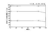
- HF removal member 3 a graph showing the removal performance of the CO and O 3.
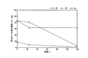
- HF removal member 4 a graph showing the removal performance of the CO and O 3.
- HF and CO in the insulating gas can be used by using an adsorbent or a catalyst removing material having a selective adsorption action depending on the polarity and a catalytic action.
- concentration of O 3 can be sufficiently reduced to ensure the life and reliability of the gas insulating device using the insulating gas containing CO 2 and O 2 as the main components in the long-term operation.
- the present invention is based on this finding.
- FIG. 1 is a partial schematic cross-sectional view of a gas insulating device (gas insulating circuit breaker) according to the present embodiment.
- the insulating gas 2 is filled in the closed container 1 made of grounded metal, a porcelain tube, or the like.
- a fixed contact portion 31 and a movable contact portion 41 are arranged to face each other in the closed container 1, and the fixed contact portion 31 and the movable contact portion 41 are provided with a fixed arc contact 32 and a movable arc contact 42, respectively.
- the high voltage portion is composed of the fixed contact portion 31 and the movable contact portion 41.
- An O-ring or the like is arranged at the sealed portion of the closed container 1 to form an airtight structure.
- the arc contacts 32 and 42 are in a contact conductive state during normal operation, and are separated by relative movement during a shutoff operation, and an arc 7 is generated in the space between both contacts 32 and 42. Further, a gas flow generating means for blowing the insulating gas 2 as an arc-extinguishing gas to the arc 7 is installed on the movable contact portion 41 side.
- a piston 43, a cylinder 44, and an insulating nozzle 45 are provided here. Further, a metal exhaust stack 33 through which the heat gas flow 8 can pass is attached to the fixed contact portion 31 side. On the movable contact portion 41 side, an exhaust rod 46 through which the heat gas flow 8 can pass is provided in series with the movable arc contact 42. Grease for reducing friction is applied to the sliding portions of the piston 43 and the cylinder 44.
- a gas containing CO 2 and O 2 as main components is used as an insulating gas that is filled in the closed container 1 and also functions as an arc-extinguishing gas.
- CO 2 is contained in an amount of 50% or more by volume, and O 2 is contained in a range not exceeding 50% by volume.
- a mixed gas of CO 2 (70%) + O 2 (30%) can be exemplified.
- the effect of the present embodiment can be obtained even when a gas having a larger molecular diameter than CO 2 is mixed with the insulating gas.
- the gas to be mixed include compounds containing fluorine and iodine such as hydrofluoromonoether, perfluoroketone, hydrofluoroolefin, perfluoronitrile and trifluoroiodomethane.
- a removing material 6 having a function of reducing the concentrations of HF, CO and O 3 in the insulating gas is installed in the closed container 1 by the case 5.
- the arrangement of the removing material 6, it is possible to obtain a more aggressive HF, the effect of reducing the concentrations of CO and O 3 by the flow path of the outlet side of the arc extinguishing gas in the exhaust pipe 33.
- the removing material 6 is, for example, a synthetic zeolite having a silica / alumina molar ratio of 5 or more (hereinafter, may be referred to as a high silica synthetic zeolite) or a synthetic zeolite having a proton (H) as a cation (hereinafter, a proton exchange synthetic zeolite). ), Metal oxides can be exemplified. Further, the removing material 6 may be a combination of two or more of high silica synthetic zeolite, proton exchange synthetic zeolite, and metal oxide.
- the removing material 6 may be made of a combination of materials other than the high silica synthetic zeolite, the proton exchange synthetic zeolite, and the metal oxide.
- a material having a rejection against HF, the mixture of materials having a rejection to the material and O 3 with removal performance for CO may be used as the removing member 6 according to the present embodiment.
- high-silica synthetic zeolite examples include high-silica zeolite having a pore size of 4.9 ⁇ and having a proton as a cation.
- proton exchange synthetic zeolite for example, a zeolite having a pore diameter of 4.9 ⁇ can be exemplified.
- the metal oxide can be exemplified CuO, a Co 3 O 4, MnO 2.
- zeolite it is generally known that the higher the mol ratio of silica (SiO 2 ) and alumina (Al 2 O 3 ), the higher the strength / reaction activity as a solid acid.
- the removing material 6 By using a high silica zeolite having a silica-alumina ratio of 5 or more as the removing material 6, the removing material 6 has a catalytic action of oxidizing CO to CO 2 as a solid acid. It also accelerates the rate at which O 3 changes to O 2 due to self-reaction.
- HF is physically adsorbed in the pores by the intermolecular force (Van der Waals force) generated by the polarity of zeolite.
- the high silica synthetic zeolite, HF, CO three kinds of unnecessary material effectively adsorb the O 3, oxides, can be reduced.
- the synthetic zeolite by converting the cation of the synthetic zeolite into a proton (H + ), it can be used as a solid acid and has a catalytic action of oxidizing CO to CO 2. It also accelerates the rate at which O 3 changes to O 2 due to self-reaction. HF is physically adsorbed in the pores by the intermolecular force (Van der Waals force) generated by the polarity of zeolite.
- the proton exchange synthetic zeolite, HF, CO three kinds of unnecessary material effectively adsorb the O 3, oxides, can be reduced.
- CuO, Co 3 O 4, MnO metal oxides such as 2 has a catalytic function in the temperature range of at least -30 °C ⁇ 50 °C. Since these metal oxides are oxidation catalysts, they have a catalytic action of oxidizing CO to CO 2. It also accelerates the rate at which O 3 changes to O 2 due to self-reaction. HF is physically adsorbed on the catalyst surface by the intermolecular force (Van der Waals force) generated by the polarity. Thus, the metal oxide, HF, CO, three kinds of unnecessary material effectively adsorb the O 3, oxides, can be reduced.
- HF is a gas that is particularly corrosive to metals and is harmful to the human body.
- CO is an addictive gas and also reduces the dielectric strength of the insulating gas.
- O 3 is also a toxic gas to humans high reactivity. Further, O 3 deteriorates the O-ring used for maintaining the airtight structure of the closed container 1 and the grease applied to the sliding portions of the piston 43 and the cylinder 44.
- the removing material 1 is a proton exchange synthetic zeolite having a silica / alumina molar ratio of 5 and a pore diameter of 4.9 ⁇
- the removing material 2 is a potassium exchange synthetic zeolite having a silica / alumina molar ratio of less than 5 and a pore diameter of 3 ⁇
- Reference numeral 3 is a sodium exchange synthetic zeolite having a silica / alumina molar ratio of less than 5 and a pore diameter of 9 ⁇
- the removing material 4 is a lithium exchange synthetic zeolite having a silica / alumina molar ratio of less than 5 and a pore diameter of 9 ⁇ .
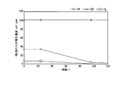
- FIGS. 2 to 5 show a graph of the removal performance of the removal materials 1 to 4.
- a horizontal axis represents time in FIGS. 2-5, the vertical axis HF shown in FIG. 1, a concentration of CO and O 3, at a generation density per breaking current energy 1MJ in the gas insulated circuit breaker (volume ppm) is there.
- removing material 1, HF it is understood that it is possible to obtain a sufficient density reduction effect with respect to all of the CO and O 3.
- the gas-insulated device of this embodiment includes a gas-insulated switchgear.
- Gas-insulated switchgear includes circuit breakers, disconnectors, ground switches, and lightning arresters.
- a removing agent by using a removing agent, can provide a gas-insulated equipment to reduce the concentration of HF, CO and O 3 in the insulating gas.
- the life and reliability of the gas insulating device using the insulating gas containing CO 2 and O 2 as the main components in long-term operation can be ensured, and the safety at the time of maintenance can be ensured.
Landscapes
- Engineering & Computer Science (AREA)
- Power Engineering (AREA)
- Gas-Insulated Switchgears (AREA)
- Circuit Breakers (AREA)
- Solid-Sorbent Or Filter-Aiding Compositions (AREA)
Abstract
Description
絶縁ガスは、密閉容器に充填されてCO2及びO2を主成分とする。
高電圧部は、前記密閉容器に収納される。
除去材は、絶縁ガス中のHF、CO及びO3の濃度を減少させる。
第1の実施形態について、図1を用いて説明する。本実施形態に係るガス絶縁機器は、パッファ形ガス絶縁遮断器である。図1は、本実施形態に係るガス絶縁機器(ガス絶縁遮断器)の一部概略断面図である。

Claims (9)
- 密閉容器と、
前記密閉容器に充填されたCO2及びO2を主成分とする絶縁ガスと、
前記密閉容器に収納された高電圧部と、
前記絶縁ガス中のHF、CO及びO3の濃度を減少させる除去材と、が備えられている、ガス絶縁機器。 - 前記除去材が、シリカ/アルミナのモル比が5以上の合成ゼオライトである、請求項1に記載のガス絶縁機器。
- 前記除去材が、陽イオンとしてプロトン(H)を持つ合成ゼオライトである、請求項1に記載のガス絶縁機器。
- 前記除去材が、金属酸化物である、請求項1に記載のガス絶縁機器。
- 前記除去材が、2種以上の材料の組み合わせからなる請求項1乃至請求項4の何れか一項に記載のガス絶縁機器。
- 前記絶縁ガスに、分子径がCO2より大きいガス成分が含まれる、請求項1乃至請求項5の何れか一項に記載のガス絶縁機器。
- 前記ガス絶縁機器は、開閉装置であって、
前記高電圧部は、
固定接触子と、
前記固定接触子に対して接離可能であって、前記固定接触子と同軸上に向かい合って配置され、開離時には前記固定接触子との間にアーク放電が発生しうるように構成された可動接触子と、
前記アーク放電に前記絶縁ガスを吹き付けるために、前記アーク放電を囲むように配置された絶縁ノズルと、
を備えたことを特徴とする請求項1乃至請求項6の何れか一項に記載のガス絶縁機器。 - 前記絶縁ノズルは、フッ素系樹脂を含むことを特徴とする請求項7に記載のガス絶縁機器。
- 前記除去材は、前記絶縁ガスが前記アーク放電に吹き付けられた後に流れうる位置に配置されたことを特徴とする請求項7または請求項8に記載のガス絶縁機器。
Priority Applications (5)
| Application Number | Priority Date | Filing Date | Title |
|---|---|---|---|
| CN201980100339.XA CN114365361A (zh) | 2019-11-22 | 2019-11-22 | 气体绝缘设备 |
| JP2021558138A JP7228714B2 (ja) | 2019-11-22 | 2019-11-22 | ガス絶縁機器 |
| EP19952951.2A EP4064481A4 (en) | 2019-11-22 | 2019-11-22 | GAS ISOLATION DEVICE |
| PCT/JP2019/045779 WO2021100194A1 (ja) | 2019-11-22 | 2019-11-22 | ガス絶縁機器 |
| US17/650,305 US12199413B2 (en) | 2019-11-22 | 2022-02-08 | Gas insulation apparatus |
Applications Claiming Priority (1)
| Application Number | Priority Date | Filing Date | Title |
|---|---|---|---|
| PCT/JP2019/045779 WO2021100194A1 (ja) | 2019-11-22 | 2019-11-22 | ガス絶縁機器 |
Related Child Applications (1)
| Application Number | Title | Priority Date | Filing Date |
|---|---|---|---|
| US17/650,305 Continuation US12199413B2 (en) | 2019-11-22 | 2022-02-08 | Gas insulation apparatus |
Publications (1)
| Publication Number | Publication Date |
|---|---|
| WO2021100194A1 true WO2021100194A1 (ja) | 2021-05-27 |
Family
ID=75981573
Family Applications (1)
| Application Number | Title | Priority Date | Filing Date |
|---|---|---|---|
| PCT/JP2019/045779 Ceased WO2021100194A1 (ja) | 2019-11-22 | 2019-11-22 | ガス絶縁機器 |
Country Status (5)
| Country | Link |
|---|---|
| US (1) | US12199413B2 (ja) |
| EP (1) | EP4064481A4 (ja) |
| JP (1) | JP7228714B2 (ja) |
| CN (1) | CN114365361A (ja) |
| WO (1) | WO2021100194A1 (ja) |
Cited By (1)
| Publication number | Priority date | Publication date | Assignee | Title |
|---|---|---|---|---|
| JP2023085791A (ja) * | 2021-12-09 | 2023-06-21 | 三菱電機株式会社 | 電力用スイッチギア |
Families Citing this family (1)
| Publication number | Priority date | Publication date | Assignee | Title |
|---|---|---|---|---|
| JP2024124633A (ja) * | 2023-03-03 | 2024-09-13 | 株式会社東芝 | ガス遮断器 |
Citations (5)
| Publication number | Priority date | Publication date | Assignee | Title |
|---|---|---|---|---|
| JP4660407B2 (ja) | 2006-03-27 | 2011-03-30 | 株式会社東芝 | ガス絶縁開閉器 |
| JP5238622B2 (ja) | 2009-06-17 | 2013-07-17 | 株式会社東芝 | ガス絶縁機器、および、その製造方法 |
| JP2014146515A (ja) * | 2013-01-29 | 2014-08-14 | Toshiba Corp | 電力用ガス絶縁機器 |
| JP2015076408A (ja) * | 2014-12-09 | 2015-04-20 | 大陽日酸東関東株式会社 | Sf6ガス回収精製装置及びsf6ガス回収精製方法 |
| WO2019106840A1 (ja) * | 2017-12-01 | 2019-06-06 | 株式会社 東芝 | ガス遮断器 |
Family Cites Families (9)
| Publication number | Priority date | Publication date | Assignee | Title |
|---|---|---|---|---|
| US4474896A (en) * | 1983-03-31 | 1984-10-02 | Union Carbide Corporation | Adsorbent compositions |
| US5417950A (en) * | 1994-07-07 | 1995-05-23 | The Boc Group, Inc. | Process for the purification of nitric oxide |
| US5810910A (en) * | 1995-10-06 | 1998-09-22 | Air Products And Chemicals, Inc. | Adsorbents for ozone recovery from gas mixtures |
| JP2002114504A (ja) | 2000-10-02 | 2002-04-16 | Toshiba Corp | Sf6ガス回収装置及び回収方法 |
| US8445398B2 (en) * | 2007-07-31 | 2013-05-21 | Exxonmobil Chemical Patents Inc. | Ion exchange process for making molecular sieve composition |
| JP2014179301A (ja) * | 2013-03-15 | 2014-09-25 | Toshiba Corp | 電力用ガス絶縁機器及びその運転方法 |
| WO2014187940A1 (en) * | 2013-05-23 | 2014-11-27 | Abb Technology Ag | Electrical apparatus comprising a contamination-reducing component |
| KR102242307B1 (ko) | 2013-11-12 | 2021-04-20 | 에이비비 슈바이쯔 아게 | 전기 에너지의 생성, 전송, 분배 및/또는 이용을 위한 co2 절연된 전기 장치용 물 및 오염 흡착제 |
| EP3069421B1 (en) * | 2013-11-12 | 2017-09-20 | ABB Schweiz AG | Water and contamination adsorber for co2 insulated electrical apparatus for the generation, transmission, distribution and/or usage of electrical energy |
-
2019
- 2019-11-22 JP JP2021558138A patent/JP7228714B2/ja active Active
- 2019-11-22 WO PCT/JP2019/045779 patent/WO2021100194A1/ja not_active Ceased
- 2019-11-22 CN CN201980100339.XA patent/CN114365361A/zh active Pending
- 2019-11-22 EP EP19952951.2A patent/EP4064481A4/en active Pending
-
2022
- 2022-02-08 US US17/650,305 patent/US12199413B2/en active Active
Patent Citations (5)
| Publication number | Priority date | Publication date | Assignee | Title |
|---|---|---|---|---|
| JP4660407B2 (ja) | 2006-03-27 | 2011-03-30 | 株式会社東芝 | ガス絶縁開閉器 |
| JP5238622B2 (ja) | 2009-06-17 | 2013-07-17 | 株式会社東芝 | ガス絶縁機器、および、その製造方法 |
| JP2014146515A (ja) * | 2013-01-29 | 2014-08-14 | Toshiba Corp | 電力用ガス絶縁機器 |
| JP2015076408A (ja) * | 2014-12-09 | 2015-04-20 | 大陽日酸東関東株式会社 | Sf6ガス回収精製装置及びsf6ガス回収精製方法 |
| WO2019106840A1 (ja) * | 2017-12-01 | 2019-06-06 | 株式会社 東芝 | ガス遮断器 |
Non-Patent Citations (1)
| Title |
|---|
| See also references of EP4064481A4 |
Cited By (2)
| Publication number | Priority date | Publication date | Assignee | Title |
|---|---|---|---|---|
| JP2023085791A (ja) * | 2021-12-09 | 2023-06-21 | 三菱電機株式会社 | 電力用スイッチギア |
| JP7539363B2 (ja) | 2021-12-09 | 2024-08-23 | 三菱電機株式会社 | 電力用スイッチギア |
Also Published As
| Publication number | Publication date |
|---|---|
| EP4064481A4 (en) | 2023-08-30 |
| US20220166198A1 (en) | 2022-05-26 |
| JPWO2021100194A1 (ja) | 2021-05-27 |
| CN114365361A (zh) | 2022-04-15 |
| JP7228714B2 (ja) | 2023-02-24 |
| EP4064481A1 (en) | 2022-09-28 |
| US12199413B2 (en) | 2025-01-14 |
Similar Documents
| Publication | Publication Date | Title |
|---|---|---|
| JP4660407B2 (ja) | ガス絶縁開閉器 | |
| JP5127569B2 (ja) | ガス絶縁開閉器 | |
| CN104051976B (zh) | 用于电力的气体绝缘装置及其操作方法 | |
| JP2011004494A (ja) | ガス絶縁機器、および、その製造方法 | |
| JP2015073348A (ja) | 電力用ガス絶縁機器 | |
| CN105874665A (zh) | 用于产生、传输、分配和/或使用电能的co2绝缘电装置的水和污染物吸收剂 | |
| KR102595009B1 (ko) | Co2로의 co 전환을 위한 세리아계 촉매를 포함하는 회로 차단기 | |
| US12199413B2 (en) | Gas insulation apparatus | |
| CN106663495A (zh) | 1,1,1,4,4,4‑六氟‑2‑丁烯用作气态电绝缘和/或灭弧介质的设备和方法 | |
| KR20240042057A (ko) | 전기 에너지의 생성, 전송 및/또는 분배를 위한 전기 장치 | |
| KR102603005B1 (ko) | Co 흡착용 금속 유기 구조체 재료를 포함하는 회로 차단기 | |
| JP2014124053A (ja) | 電力用ガス絶縁機器 | |
| WO2026013893A1 (ja) | ガス絶縁機器 |
Legal Events
| Date | Code | Title | Description |
|---|---|---|---|
| 121 | Ep: the epo has been informed by wipo that ep was designated in this application |
Ref document number: 19952951 Country of ref document: EP Kind code of ref document: A1 |
|
| ENP | Entry into the national phase |
Ref document number: 2021558138 Country of ref document: JP Kind code of ref document: A |
|
| NENP | Non-entry into the national phase |
Ref country code: DE |
|
| ENP | Entry into the national phase |
Ref document number: 2019952951 Country of ref document: EP Effective date: 20220622 |
|
| WWG | Wipo information: grant in national office |
Ref document number: 202217006386 Country of ref document: IN |