WO2021100323A1 - 医療デバイス、および処置方法 - Google Patents
医療デバイス、および処置方法 Download PDFInfo
- Publication number
- WO2021100323A1 WO2021100323A1 PCT/JP2020/036895 JP2020036895W WO2021100323A1 WO 2021100323 A1 WO2021100323 A1 WO 2021100323A1 JP 2020036895 W JP2020036895 W JP 2020036895W WO 2021100323 A1 WO2021100323 A1 WO 2021100323A1
- Authority
- WO
- WIPO (PCT)
- Prior art keywords
- shaft
- energy
- wall
- medical device
- blood vessel
- Prior art date
- Legal status (The legal status is an assumption and is not a legal conclusion. Google has not performed a legal analysis and makes no representation as to the accuracy of the status listed.)
- Ceased
Links
Images







Classifications
-
- A—HUMAN NECESSITIES
- A61—MEDICAL OR VETERINARY SCIENCE; HYGIENE
- A61B—DIAGNOSIS; SURGERY; IDENTIFICATION
- A61B18/00—Surgical instruments, devices or methods for transferring non-mechanical forms of energy to or from the body
- A61B18/18—Surgical instruments, devices or methods for transferring non-mechanical forms of energy to or from the body by applying electromagnetic radiation, e.g. microwaves
- A61B18/1815—Surgical instruments, devices or methods for transferring non-mechanical forms of energy to or from the body by applying electromagnetic radiation, e.g. microwaves using microwaves
-
- A—HUMAN NECESSITIES
- A61—MEDICAL OR VETERINARY SCIENCE; HYGIENE
- A61B—DIAGNOSIS; SURGERY; IDENTIFICATION
- A61B18/00—Surgical instruments, devices or methods for transferring non-mechanical forms of energy to or from the body
- A61B18/04—Surgical instruments, devices or methods for transferring non-mechanical forms of energy to or from the body by heating
- A61B18/12—Surgical instruments, devices or methods for transferring non-mechanical forms of energy to or from the body by heating by passing a current through the tissue to be heated, e.g. high-frequency current
- A61B18/14—Probes or electrodes therefor
-
- A—HUMAN NECESSITIES
- A61—MEDICAL OR VETERINARY SCIENCE; HYGIENE
- A61N—ELECTROTHERAPY; MAGNETOTHERAPY; RADIATION THERAPY; ULTRASOUND THERAPY
- A61N7/00—Ultrasound therapy
- A61N7/02—Localised ultrasound hyperthermia
- A61N7/022—Localised ultrasound hyperthermia intracavitary
-
- A—HUMAN NECESSITIES
- A61—MEDICAL OR VETERINARY SCIENCE; HYGIENE
- A61B—DIAGNOSIS; SURGERY; IDENTIFICATION
- A61B18/00—Surgical instruments, devices or methods for transferring non-mechanical forms of energy to or from the body
- A61B2018/00053—Mechanical features of the instrument of device
- A61B2018/00107—Coatings on the energy applicator
-
- A—HUMAN NECESSITIES
- A61—MEDICAL OR VETERINARY SCIENCE; HYGIENE
- A61B—DIAGNOSIS; SURGERY; IDENTIFICATION
- A61B18/00—Surgical instruments, devices or methods for transferring non-mechanical forms of energy to or from the body
- A61B2018/00315—Surgical instruments, devices or methods for transferring non-mechanical forms of energy to or from the body for treatment of particular body parts
- A61B2018/00345—Vascular system
- A61B2018/00404—Blood vessels other than those in or around the heart
-
- A—HUMAN NECESSITIES
- A61—MEDICAL OR VETERINARY SCIENCE; HYGIENE
- A61B—DIAGNOSIS; SURGERY; IDENTIFICATION
- A61B18/00—Surgical instruments, devices or methods for transferring non-mechanical forms of energy to or from the body
- A61B2018/00315—Surgical instruments, devices or methods for transferring non-mechanical forms of energy to or from the body for treatment of particular body parts
- A61B2018/00434—Neural system
-
- A—HUMAN NECESSITIES
- A61—MEDICAL OR VETERINARY SCIENCE; HYGIENE
- A61B—DIAGNOSIS; SURGERY; IDENTIFICATION
- A61B18/00—Surgical instruments, devices or methods for transferring non-mechanical forms of energy to or from the body
- A61B2018/00571—Surgical instruments, devices or methods for transferring non-mechanical forms of energy to or from the body for achieving a particular surgical effect
- A61B2018/00577—Ablation
-
- A—HUMAN NECESSITIES
- A61—MEDICAL OR VETERINARY SCIENCE; HYGIENE
- A61B—DIAGNOSIS; SURGERY; IDENTIFICATION
- A61B18/00—Surgical instruments, devices or methods for transferring non-mechanical forms of energy to or from the body
- A61B2018/00994—Surgical instruments, devices or methods for transferring non-mechanical forms of energy to or from the body combining two or more different kinds of non-mechanical energy or combining one or more non-mechanical energies with ultrasound
-
- A—HUMAN NECESSITIES
- A61—MEDICAL OR VETERINARY SCIENCE; HYGIENE
- A61B—DIAGNOSIS; SURGERY; IDENTIFICATION
- A61B18/00—Surgical instruments, devices or methods for transferring non-mechanical forms of energy to or from the body
- A61B18/18—Surgical instruments, devices or methods for transferring non-mechanical forms of energy to or from the body by applying electromagnetic radiation, e.g. microwaves
- A61B18/1815—Surgical instruments, devices or methods for transferring non-mechanical forms of energy to or from the body by applying electromagnetic radiation, e.g. microwaves using microwaves
- A61B2018/1861—Surgical instruments, devices or methods for transferring non-mechanical forms of energy to or from the body by applying electromagnetic radiation, e.g. microwaves using microwaves with an instrument inserted into a body lumen or cavity, e.g. a catheter
-
- A—HUMAN NECESSITIES
- A61—MEDICAL OR VETERINARY SCIENCE; HYGIENE
- A61N—ELECTROTHERAPY; MAGNETOTHERAPY; RADIATION THERAPY; ULTRASOUND THERAPY
- A61N7/00—Ultrasound therapy
- A61N2007/0004—Applications of ultrasound therapy
- A61N2007/0021—Neural system treatment
- A61N2007/003—Destruction of nerve tissue
-
- A—HUMAN NECESSITIES
- A61—MEDICAL OR VETERINARY SCIENCE; HYGIENE
- A61N—ELECTROTHERAPY; MAGNETOTHERAPY; RADIATION THERAPY; ULTRASOUND THERAPY
- A61N7/00—Ultrasound therapy
- A61N2007/0043—Ultrasound therapy intra-cavitary
Definitions
- the present invention relates to a medical device and a treatment method.
- Medical devices that radiate energy in the biological organs of the human body and are used to treat or improve various diseases are known.
- a procedure of cauterizing nerves existing outside a blood vessel is performed.
- radio frequency (RF) in the radio frequency band may be selected as the type of energy.
- RF directly heats the inner wall of the blood vessel by Joule heat by radiating energy in a state where the energy radiating part is in direct contact with the inner wall of the blood vessel to which energy is applied, and by the heat propagation. It indirectly raises the temperature of nerves located outside the blood vessels. Therefore, when RF is adopted, heat damage to blood vessels that are directly heated is inevitable, and it is necessary to keep the output low in order to avoid complications such as perforation of blood vessels and narrowing of blood vessels. Therefore, in the procedure using RF, the cauterization depth must be shallow, and there is a possibility that denervation cannot be performed reliably.
- the operator applies energy to a plurality of locations in the circumferential direction and the extension direction of the blood vessel, so that the energy is locally concentrated on a part of the inner wall of the blood vessel. Perform denervation of nerves located outside the blood vessels while avoiding.
- energy such as microwaves and ultrasonic waves is radiated in a state of non-contact with the inner wall of the blood vessel, and the energy is used to the outside of the blood vessel. It is also possible to adopt an energy radiating part that can slow down the located nerve. When such an energy radiating part is adopted, it is not necessary to bring the energy radiating part into direct contact with the inner wall of the blood vessel, so that the inner wall of the blood vessel is protected from excessive heat damage and the deeper nerves are cauterized. Can be done.
- the energy radiating part for example, an antenna or an element
- the energy radiating part is generally larger than the RF electrode
- an advanced catheter operation technique is required, and the treatment success rate varies depending on the operator.
- a catheter device equipped with one energy radiating part is used, and energy is radiated from the energy radiating part located at the center of the cross section of the blood vessel with high output in the entire circumferential direction.
- the present invention has been made based on the above-mentioned problems, and the energy is locally applied to the treatment target site by an energy radiating unit capable of irradiating the living organ with energy in a non-contact state. Allows you to irradiate. As a result, it is possible to more reliably reduce nerves with a simpler operation while suppressing the energy radiated from the energy radiating portion from becoming excessively large.
- the medical device includes a shaft in which a lumen is formed, a guide portion that can be inserted into a living organ, and a state in which the shaft is arranged in the lumen, and is outside the living organ. It has a treatment part including an energy radiating part capable of radiating energy that can reach the surrounding nerves existing in the shaft, and a tip portion of the shaft is configured to be able to abut on the inner wall of the living organ.
- One part and one part are arranged closer to the base end side of the shaft than the first part, and can be brought into contact with the inner wall of the living organ at a position different from that of the first part on the cross section of the inner wall of the living organ.
- the shaft is formed in a state where at least a part of the first part and at least a part of the second part are in contact with the inner wall of the living organ. Can move through the lumen of the organ.
- a guide portion including a shaft in which a lumen is formed is inserted into a living organ, and a first portion formed at the tip of the shaft is formed on the inner wall of the living lumen.
- the second part formed on the proximal end side of the shaft with respect to the first part is brought into contact with the second part on the cross section of the inner wall of the biological organ with respect to a position different from the first part.
- a treatment part provided with an energy radiating part is placed along the lumen of the shaft.
- the energy radiating portion is arranged in the lumen of the shaft, the energy radiating portion is radiated from the energy radiating portion, and the energy is transmitted to the surrounding nerve existing outside the biological organ.
- the shaft can be held against the living organ by bringing the first part of the shaft of the guide part and the second part of the shaft of the guide part into contact with the inner wall of the living organ.
- the surgeon moves the treatment part along the lumen of the shaft while holding the shaft against the living organ, and arranges the energy radiating part of the treatment part at a position close to the inner wall of the living organ.
- a predetermined treatment target site for example, a peripheral nerve located outside a blood vessel
- the surgeon can more reliably perform denervation while preventing the occurrence of burns and the like.
- FIG. 1 It is a figure which shows schematic the whole structure of the medical device which concerns on embodiment. It is a perspective view which shows the tip part of a shaft enlarged. It is sectional drawing of the tip part of a shaft. It is a flowchart which shows the procedure of the treatment method which concerns on embodiment. It is a figure which shows typically the blood vessel to which the treatment method is applied. It is sectional drawing of the blood vessel which shows typically the state at the time of carrying out the treatment method using the medical device which concerns on embodiment. It is sectional drawing of the blood vessel which shows typically the state at the time of carrying out the treatment method using the medical device which concerns on embodiment. It is a perspective view which shows typically the state at the time of carrying out the treatment method using the medical device which concerns on embodiment.
- FIG. 9A-9A It is sectional drawing (cross-sectional view) of the blood vessel along the arrow 9A-9A shown in FIG. It is a figure which shows schematic the whole structure of the medical device which concerns on modification 1.
- FIG. It is an enlarged perspective view which shows the tip part of the shaft of the medical device which concerns on modification 2.
- FIG. 5 is an enlarged perspective view showing a tip portion of the medical device according to the third modification.
- FIG. 1 to 3 are diagrams provided for explaining each part of the medical device 10 according to the embodiment.
- FIG. 4 is a flowchart showing a procedure example of a treatment method using the medical device 10.
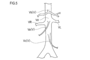
- FIG. 5 is a diagram for explaining a blood vessel V which is a target of a treatment method using the medical device 10.
- 6 to 9 are diagrams for explaining a usage example of the medical device 10.
- 8 is a perspective view schematically showing a state when the guide portion 100 and the treatment portion 200 are arranged in the blood vessel V
- FIG. 9 is a blood vessel along the direction indicated by arrows 9A-9A in FIG. It is a cross-sectional view of V.
- FIG. 5 indicates the right renal artery
- VL indicates the left renal artery
- reference numeral Va indicates a superior mesenteric artery
- reference numeral Vb indicates a celiac artery
- reference numeral Vc indicates an inferior mesenteric artery
- reference numeral Vd indicates an aorta.
- an operator such as a doctor (hereinafter referred to as “operator”) autonomously operates in a blood vessel V having a peripheral nerve (abducens nerve) Na that innervates the intestinal tract of the patient.
- a peripheral nerve an auditory nerve
- the peristaltic movement of the intestinal tract is enhanced.
- the surgeon performs at least one symptom of abdominal bloating, abdominal pain, peristal discomfort, and frequent stools due to constipation and / or abnormal peristaltic movements of the intestinal tract. Relief of constipation in patients and / or at least one of the symptoms caused by abnormal peristaltic movements of the intestinal tract can be promoted.
- the blood vessel V to which the treatment method is applied may enhance the peristaltic movement of the intestinal tract of the patient (subject) by being subjected to a predetermined treatment according to the embodiment (for example, application of energy by microwaves described later).
- a predetermined treatment for example, application of energy by microwaves described later.
- the blood vessel V for example, at least one of a superior mesenteric artery Va, a celiac artery Vb, and an inferior mesenteric artery Vc can be preferably selected.
- the operator applies energy to one peripheral nerve Na or a plurality of peripheral nerve Na as the treatment according to the embodiment.
- the operator enhances the peristaltic movement of the intestinal tract by damaging the peripheral nerve Na and completely or partially blocking the autonomic nerve transmission to the gastrointestinal tract by the peripheral nerve Na.
- the following mechanism is considered as the reason why the peristaltic movement of the intestinal tract is activated by performing the above-mentioned treatment for reducing the activity of the autonomic nerve in the blood vessel V.
- the sympathetic nervous system among the sympathetic nervous system and the parasympathetic nervous system becomes It is relatively weakened and becomes parasympathetic dominant.
- the enteric nervous system that autonomously controls intestinal motility in the periphery becomes dominant, and intestinal peristalsis is activated.
- activation of intestinal peristalsis promotes and normalizes colonic transit time, resulting in abdominal bloating, abdominal pain, perineal discomfort, and frequent stools due to constipation and / or abnormal intestinal peristalsis. Relief of at least one of these symptoms is promoted.
- the intestinal peristaltic movement of the large intestine is reduced, and as a result, the passage time of the stool is delayed, resulting in constipation. It is possible to preferably promote the relief of the symptoms of constipation with delayed colonic transit time.
- the treatment target site (region containing one or more peripheral nerve Na) S shown in FIG. 6 is not particularly limited as long as it can enhance the peristaltic movement of the intestinal tract.
- treatment may be performed on an arbitrary range (site) of the traveling direction (extending direction) of the blood vessel V, or in the circumferential direction of the blood vessel V (circumferential direction of the cross section). Treatment may be performed on the range (site) of. Further, the treatment may be performed a plurality of times on a plurality of arbitrary points of the same blood vessel V, or may be performed a plurality of times on an arbitrary position of a plurality of different blood vessels V. May be good.
- the treatment method according to the present embodiment includes performing treatment around the origin of the superior mesenteric artery Va.
- the treatment target site S preferably includes a range of 0 mm to 20 mm along the extension direction of the superior mesenteric artery Va, for example, with reference to the opening of the superior mesenteric artery Va.
- the application of energy from the superior mesenteric artery Va is performed by the superior mesentery. It is even more preferable to carry out only within the range of 0 mm to 20 mm along the extension direction of the artery Va.
- the branch portion of the superior mesenteric artery Va is used as a reference for the treatment target site S.
- the range of 0 mm to 100 mm may be included along the extension direction of the aorta Vd.
- the depth of energy from the superior mesenteric artery Va side is preferably included in the range of 1 mm to 6 mm from the intima of the superior mesenteric artery Va.
- the peripheral nerve Na existing outside the superior mesenteric artery Va exists at a relatively deep position around the origin of the superior mesenteric artery Va. More specifically, the peripheral nerve Na is present in bundles in the adipose tissue outside the superior mesenteric artery Va, supported by connective tissue. Therefore, when applying energy from around the origin of the superior mesenteric artery Va, the energy reaches a position of 1 mm to 6 mm in the intima of the superior mesenteric artery Va, thereby causing the superior mesenteric artery Va. Peripheral nerve Na can be efficiently denervated.
- the medical device 10 As shown in FIGS. 1, 2 and 3, the medical device 10 according to the present embodiment has a guide unit 100 and a treatment unit 200.
- the guide portion 100 has a shaft 110 and a hub 120 arranged at a base end portion of the shaft 110.
- the treatment unit 200 includes an energy radiating unit 210, a main body unit 220, and an auxiliary member 230.
- the medical device 10 can be configured as a catheter device in which the guide unit 100 and the treatment unit 200 are integrally assembled.
- the guide portion 100 has a shaft 110 in which a lumen 113 (see FIG. 9) is formed.
- the shaft 110 is configured to be insertable into the blood vessel V.
- FIG. 2 shows the shaft 110 in a natural state to which no external force is applied. At least a portion of the tip of the shaft 110 extends along the axial direction of the shaft 110 in its natural state. The tip of the shaft 110 is the end of the shaft 110 located on the insertion direction side into the living body.
- a first portion 115a and a second portion 115b are formed at the tip of the shaft 110.
- the first portion 115a is configured to be able to come into contact with the inner wall Vai of the blood vessel V.
- the second portion 115b is arranged closer to the proximal end side of the shaft 110 than the first portion 115a.
- the second site 115b is configured to be able to come into contact with the inner wall Vai of the blood vessel V at a position different from that of the first site 115a on the cross section of the inner wall Vai of the blood vessel V.
- a spiral portion 115 in which a part of the shaft 110 extends spirally is formed at the tip end portion of the shaft 110.
- Each of the first portion 115a and the second portion 115b is composed of a part of the spiral portion 115.
- the first portion 115a and the second portion 115b can be defined at arbitrary portions in the extending direction and the circumferential direction of the spiral portion 115.
- the spiral portion 115 can have, for example, a shape in the counterclockwise direction indicated by an arrow R with respect to a predetermined reference axis A.
- the reference axis A can be defined, for example, by a straight line extending parallel to the base side portion 118 extending linearly of the shaft 110.
- the specific shape of the spiral portion 115 (for example, the pitch of the spiral, the number of turns, the outer diameter of the spiral, the winding direction of the spiral, etc.) is the first portion 115a and the second portion 115a when the shaft 110 is arranged in the blood vessel V.
- the site 115b is not particularly limited as long as it can be brought into contact with the inner wall Vai of the blood vessel V.
- the portion from the first portion 115a to the second portion 115b is continuously brought into contact with the inner wall Vai of the blood vessel V. It is configured.
- the first portion 115a to the second portion 115b are composed of a part of the spiral portion 115.
- the spiral portion 115 When the spiral portion 115 is inserted into the blood vessel V, the spiral portion 115 extends in a spiral shape in the blood vessel V and abuts in a connected state within a predetermined range of the inner wall Vai of the blood vessel V.
- the first portion 115a and the second portion 115b included in the spiral portion 115 come into contact with the inner wall Vai of the blood vessel V at positions different from each other in the extending direction of the blood vessel V. Further, the first site 115a and the second site 115b come into contact with the inner wall Vai of the blood vessel V at different positions in the circumferential direction of the blood vessel V. In this way, the shaft 110 can arrange the first portion 115a and the second portion 115b at positions close to the inner wall Vai of the blood vessel V.
- the operator moves the energy radiating portion 210 along the spiral portion 115 in a state where the first portion 115a and the second portion 115b are arranged in the blood vessel V as described above, so that the operator can move the energy radiating portion 210 along the spiral portion 115 to any position of the spiral portion 115.
- the energy radiating unit 210 can be selectively arranged in the space.
- the operator radiates energy from the energy radiating portion 210 in a state where the energy radiating portion 210 is arranged at an arbitrary position of the spiral portion 115, thereby radiating energy from a position close to the inner wall Vai of the blood vessel V to the surrounding nerve Na.
- energy can be applied locally.
- the shaft 110 can secure a larger contact area of the shaft 110 with respect to the inner wall Vai of the blood vessel V. As a result, the shaft 110 is held more stably with respect to the blood vessel V.
- the energy emitting unit 210 can be arranged at any position in the direction. Therefore, energy can be easily and efficiently applied to the surrounding nerve Na from a position close to the inner wall Vai of the blood vessel V.
- the shaft 110 is preformed in the shape in which the spiral portion 115 shown in FIG. 2 is formed.
- the shaft 110 may be configured to form a substantially linear shape as a whole when introduced into a living body, and to be deformed into the shape shown in FIG. 2 when delivered to the blood vessel V.
- a member having a higher rigidity than the shaft 110 such as a guide wire W
- the shape can be reversibly deformed into a linear shape and a shape in which the spiral portion 115 is formed.
- the shaft 110 can be provided with a guide wire lumen formed over the entire length of the shaft 110 in the cavity through which the treatment portion 200 is inserted.
- the shaft 110 may be formed of, for example, a part of the shaft 110 made of a material having a temperature responsiveness that deforms in response to a temperature change or the like, and the spiral portion 115 may be formed by adjusting the temperature. it can.
- the shaft 110 has a curved portion 116 located on the proximal end side of the second portion 115b.
- the curved portion 116 can be configured so that the portion located on the tip end side of the shaft 110 with respect to the curved portion 116 is deflected with respect to the portion located on the proximal end side of the shaft 110 with respect to the curved portion 116.
- the curved portion 116 is shaped so as to be bent so that a part of the shaft 110 is folded back toward the base side portion 118.
- the folding direction of the curved portion 116 is indicated by an arrow C in FIG.
- the position where the curved portion 116 is provided on the shaft 110 and the specific shape (curvature direction, curvature, length, etc.) of the curved portion 116 are not particularly limited.
- the superior mesenteric artery Va branches from the aorta Vd and then sharply bends toward the lower limbs and runs almost in parallel with the aorta Vd. Therefore, when the treatment with the medical device 10 is performed from the lower limb side, it is not easy to deliver the medical device 10 into the superior mesenteric artery Va.
- the portion located on the tip end side of the shaft 110 is positioned closer to the proximal end side of the shaft 110 than the curved portion 116 by the curved portion 116 formed on the proximal end side of the second portion 115b of the shaft 110. It can be deflected with respect to the part to be Therefore, even in the approach from the lower limb side via the aorta Vd, it becomes easy to introduce the portion located on the distal end side of the shaft 110 into the superior mesenteric artery Va.
- the surgeon can insert the medical device 10 into the femoral artery from the inguinal region of the patient and move it to the aorta Vd, for example.
- the insertion length of the medical device 10 in the living body is shortened. Therefore, the operator can operate the medical device 10 relatively easily in the living body.
- the curved portion 116 with respect to the inner wall Vai of the blood vessel V located around the origin of the superior mesenteric artery Va. May be brought into contact with each other. Thereby, the holding force of the shaft 110 with respect to the inner wall Vai of the blood vessel V can be increased.
- the shaft 110 has a tip side portion 117 arranged on the tip end side of the first portion 115a and a base side portion 118 arranged on the base end side of the curved portion 116. ..
- the tip side portion 117 extends in a direction away from the base side portion 118 in a natural state where no external force is applied.
- a tip can be attached to the tip of the tip side portion 117.
- the tip tip can be made of, for example, a flexible resin material.
- the base side portion 118 extends substantially in a straight line.
- a hub 120 is attached to the base end of the base side portion 118.
- the hub 120 has an operation unit 121 that allows the main body portion 220 (see FIG. 3) of the treatment unit 200 to be slidably movable relative to the shaft 110 by operation at hand.
- the operation unit 121 is mechanically connected to the treatment unit 200 inserted into the lumen 113 of the shaft 110.
- the operation unit 121 can be configured to slide and move the treatment unit 200 in the cavity 113 of the shaft 110, for example, in accordance with the rotation operation in the directions of arrows r1-r2 shown in FIG.
- the operation unit 121 is configured to, for example, move the operation unit 121 forward and backward so as to slide the treatment unit 200 in conjunction with the advance / retreat movement, or fix the position of the treatment unit 200 before and after the movement. It may have a locking mechanism.
- a filling member 114 can be arranged at the tip of the cavity 113 of the shaft 110.
- a space portion 113a that allows the treatment portion 200 to move can be provided on the base end side of the filling member 114.
- the filling member 114 partitions the region in which the treatment portion 200 is housed in the lumen 113 and the region in which the guide wire lumen 114a is formed in the lumen.
- a guide wire lumen 114a through which the guide wire W can be inserted can be formed inside the filling member 114.
- the guide wire lumen 114a communicates between an arbitrary position of the tip end side portion 117 located on the tip end side of the shaft 110 and the tip opening 110a of the shaft 110. That is, the medical device 10 is configured as a monorail type catheter device in which the guide wire lumen 114a is formed only on the distal end side of the shaft 110.
- the shaft 110 can be made of a flexible member.
- the material used for the shaft 110 is not particularly limited, but for example, a material similar to the resin material used for a known catheter device can be used.
- the shaft 110 may be made of, for example, a single-layer or multi-layer resin tube member, or may have a blade wire or the like for reinforcing rigidity embedded therein. Further, the outer surface of the shaft 110 may be coated with a hydrophilic coat or the like. Further, the outer diameter, inner diameter, axial length, cross-sectional shape, etc. of the shaft 110 are not particularly limited. Further, there are no particular restrictions on the material of the filling member 114 filled in the shaft 110, the axial length in which the filling member 114 is filled, the axial length and position of the space 113a, and the like.
- the treatment unit 200 is an energy radiating unit capable of radiating energy that can reach the surrounding nerve Na located outside the blood vessel V in a state of being arranged in the lumen 113 of the shaft 110. It has a 210 and a main body 220 having an energy radiating portion 210 arranged at the tip and inserted into the lumen 113 of the shaft 110.
- the treatment unit 200 moves the lumen 113 of the shaft 110 in a state where at least a part of the first portion 115a of the shaft 110 is in contact with the inner wall Vai of the blood vessel V. It is possible.
- Arrows f in FIGS. 2 and 3 indicate the direction in which the treatment portion 200 advances along the lumen 113 of the shaft 110.
- the arrow b indicates the direction in which the treatment portion 200 retracts along the lumen 113 of the shaft 110.
- the energy radiating unit 210 can be configured to radiate microwaves or ultrasonic waves, for example.
- the energy radiating unit 210 can be composed of, for example, an antenna element when the energy radiating unit 210 is configured to be able to radiate microwaves.
- the energy radiating unit 210 can set the center frequency of the antenna element to, for example, 915 MHz, 2.45 GHz, 5.8 GHz, or 24.125 GHz. ..
- the energy radiating unit 210 When the energy radiating unit 210 is configured to be able to radiate ultrasonic waves, the energy radiating unit 210 can be composed of, for example, an ultrasonic element.
- the energy radiating unit 210 radiates energy from the cavity 113 of the shaft 110, and causes the energy to reach the surrounding nerve Na existing outside the blood vessel V to slow down the nerve, and has a specific structure and radiation as long as possible.
- the type of energy to be radiated, the maximum output of energy, etc. are not particularly limited. However, the energy radiating unit 210 more reliably slows down the surrounding nerve Na existing outside the blood vessel V even when energy is applied in a state where the energy is not in direct contact with the inner wall Vai of the blood vessel V. It is preferably configured to be able to radiate microwaves or ultrasonic waves so that this is possible.
- the main body 220 of the treatment unit 200 can be configured with a known coaxial cable capable of supplying a current to the antenna element, for example, when the energy radiation unit 210 is composed of an antenna element.
- the specific configuration of the main body 220 is not particularly limited as long as it can move in the lumen 113 while being inserted into the lumen 113 of the shaft 110.
- the main body 220 can be configured by, for example, an arbitrary structure according to the structure of the energy radiating unit 210.
- Only one energy radiating unit 210 can be provided in the treatment unit 200.
- the diameter of the main body portion 220 can be reduced.
- the diameter of the lumen 113 of the shaft 110 into which the main body 220 is inserted can be reduced. Thereby, the outer diameter of the shaft 110 can be reduced.
- the treatment unit 200 has an auxiliary member 230 arranged on the tip side of the energy radiation unit 210.
- the auxiliary member 230 assists the movement of the energy radiating portion 210 by sliding with respect to the shaft 110 when the energy radiating portion 210 moves in the cavity 113 of the shaft 110.
- the auxiliary member 230 assists the movement of the energy radiating unit 210 on the tip side of the energy radiating unit 210. Therefore, the operator can smoothly move the energy radiating portion 210 along the first portion 115a to which the spiral shape is given.
- the auxiliary member 230 can be made of, for example, a resin material. In drawings other than FIG. 3, the auxiliary member 230 is not shown.
- the space 113a of the cavity 113 formed on the tip end side of the auxiliary member 230 defines the amount of movement of the treatment unit 200 and the forward limit position of the treatment unit 200.
- the treatment unit 200 can advance to a position where it abuts on the base end of the filling member 114 arranged on the tip end side of the space unit 113a. Therefore, it is possible to prevent the treatment unit 200 from unnecessarily moving to the tip end side of the shaft 110. Therefore, the operator can easily move the energy radiating portion 210 within the range in which the spiral portion 115 is formed.
- the radiation of energy by the energy radiating unit 210 can be controlled, for example, via a predetermined controller (control device) 300 shown in FIG.
- the controller 300 can be connected to the energy radiating unit 210 via an energy transfer mechanism such as a signal line or an electric wire derived from the hub 120, for example.
- controller 300 for example, a known control device including a CPU and a storage unit can be used.
- the storage unit is equipped with a ROM for storing various programs and data, a RAM for temporarily storing programs and data as a work area, a hard disk capable of storing various programs and data, and the like.
- the storage unit can store a series of programs necessary for controlling the operation of the treatment unit 200.
- the mode of transmitting the operation command to the treatment unit 200 is, for example, a wired one via a telecommunication line, a wireless one not via a telecommunication line, an input from an operator via an operation unit incorporated in the controller, or the like.
- a device that transmits based on the above, a device that transmits based on an input from an external communication means or the like prepared as a device separate from the controller, and the like can be mentioned, but the specific form is not particularly limited.
- Treatment using the energy radiating unit 210 is, for example, a treatment robot or the like that substitutes the work by the operator. It may be carried out by the medical device of. In this case, the treatment may be performed by an operator or the like in a medical field such as an operating room, or the treatment robot may be controlled in a remote location.
- the system in which the medical device 10 and the controller 300 shown in FIG. 1 are combined can be provided as a medical system for carrying out a denervation.
- the medical device 10 is used for a procedure of enhancing the peristaltic movement of the intestinal tract by applying energy to the peripheral nerve Na running around the blood vessel V (superior mesenteric artery Va) and damaging the peripheral nerve Na. An example of doing so will be described.
- the treatment procedure described in the present specification is only an example, and for example, some procedures, procedures not particularly explained, medical devices other than the medical device 10 used in the procedure, and the like are known in the medical field. It is possible to adopt the thing as appropriate.
- the treatment method includes a step (S11) of delivering the guide portion 100 and the treatment portion 200 into the blood vessel V, and the first portion 115a and the second portion of the shaft 110.
- the operator delivers the shaft 110 into which the treatment unit 200 is inserted to the blood vessel V.
- the operator can use the guide wire W (see FIG. 3) to deliver the shaft 110 to the vessel V.
- the operator brings the first portion 115a and the second portion 115b formed at the tip of the shaft 110 into contact with the inner wall Vai of the blood vessel V.
- the operator can hold the shaft 110 against the blood vessel V by bringing the first site 115a and the second site 115b into contact with the inner wall Vai of the blood vessel V.
- the operator arranges the energy radiating portion 210 in the spiral portion 115 including the first portion 115a and the second portion 115b, whereby the energy radiating portion 210 is placed in the blood vessel V. It can be brought close to the inner wall Vai.
- the operator radiates energy from the energy radiating portion 210 arranged in the lumen 113 of the shaft 110 in a state where the first site 115a and the second site 115b are in contact with the inner wall Vai of the blood vessel V.
- the operator can locally apply energy to a predetermined treatment target site S.
- the operator may apply energy to different parts in the extending direction of the blood vessel V and different parts in the circumferential direction of the blood vessel V. it can.
- the surgeon applies energy to the vicinity of the origin of the superior mesenteric artery Va (the range of denervation) in the outer peripheral direction of the superior mesenteric artery Va, for example, 50% or less (blood vessel V). It can be set to a range of 180 ° or less in the circumferential direction on the cross section of.
- the denervation range is 50% or more in the outer peripheral direction of the superior mesenteric artery Va, the enhancement of peristaltic movement after denervation may be excessively promoted. Therefore, it is preferable to denervate within the above range.
- the first portion 115a and the second portion 115b formed on the shaft 110 of the guide portion 100 are brought into contact with the inner wall Vai of the blood vessel V.
- the shaft 110 can be held against the blood vessel V.
- the operator moves the treatment unit 200 along the lumen 113 of the shaft 110 to bring the energy radiating unit 210 of the treatment unit 200 close to the inner wall Vai of the blood vessel V.
- energy can be locally applied to the treatment target site S. Therefore, the denervation can be performed more reliably while suppressing the energy radiated from the energy radiating unit 210 to a low level.
- FIG. 10 shows the medical device 10A according to the first modification.
- the medical device 10A includes a catheter device in which the guide unit 100A and the treatment unit 200A are separate bodies.
- the surgeon inserts the energy radiating portion 210 and the main body portion 220 of the treatment portion 200A into the lumen 113 of the shaft 110A when performing the treatment using the medical device 10A. Similar to the procedure described in the above-described embodiment, the surgeon brings the first portion 115a of the shaft 110 and the second portion 115b of the shaft 110A into contact with the inner wall Vai of the blood vessel V, and the lumen of the shaft 110A. By radiating energy from the energy radiating unit 210 arranged at 113, energy can be locally applied to the treatment target site S.
- each of the guide unit 100A and the treatment unit 200A described in this modification is a medical device used for a procedure of radiating energy from the inside of the blood vessel V and denervating the surrounding nerve Na existing outside the blood vessel V. It can also be configured independently. That is, the guide unit 100A can be configured as a guide device, and the treatment unit 200A can be configured as a treatment device.
- FIG. 11 shows the medical device 10B according to the second modification.
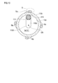
- 12 and 13 schematically show an example of a treatment method using the medical device 10B according to the second modification.
- FIG. 13 is a cross-sectional view of the blood vessel V along the arrows 13A-13A shown in FIG.
- a spiral portion 115 is formed at the tip of the shaft 110 of the guide portion 100 (see FIG. 2).
- the spiral portion 115 is not formed on the shaft 110B included in the guide portion 100B of the medical device 10B according to the second modification.
- the tip of the shaft 110B according to the second modification is given a shape curved in a direction intersecting the axial direction of the shaft 110B.
- the tip of the shaft 110B forms a first portion 115a that can come into contact with the inner wall Vai of the blood vessel V.
- the curved apex arranged on the proximal end side of the shaft 110B with respect to the first portion 115a forms the second portion 115b capable of contacting the inner wall Vai of the blood vessel V.
- the operator arranges the first site 115a and the second site 115b so as to make point contact with the inner wall Vai of the blood vessel V, as shown in FIG. be able to.
- the first site 115a and the second site 115b come into contact with the inner wall Vai of the blood vessel V at different positions in the extending direction of the blood vessel V.
- an angle of 180 ° is provided between the first site 115a and the second site 115b along the circumferential direction of the blood vessel V. Therefore, the first site 115a and the second site 115b can be arranged at opposite positions with the center OA on the cross section of the blood vessel V in between.
- the angle between the first site 115a and the second site 115b is not particularly limited as long as the first site 115a and the second site 115b can be arranged at different positions in the cross section of the blood vessel V. That is, the angle between the first portion 115a and the second portion 115b may be an angle other than 180 °.
- the operator formed a portion 119a formed between the first portion 115a and the second portion 115b on the shaft 110B and a portion 119a formed on the shaft 110B on the proximal end side of the second portion 115b.
- the formed portion 119b can be arranged so as not to abut on the inner wall Vai of the blood vessel V.
- the surgeon can bring the energy radiating portion 210 closer to the inner wall Vai of the blood vessel V by arranging the energy radiating portion 210 at the first portion 115a which is in contact with the inner wall Vai of the blood vessel V.
- the operator can locally apply energy to the treatment target site S by radiating energy from the energy radiating portion 210 close to the inner wall Vai of the blood vessel V.
- surgeon can bring the energy radiating portion 210 closer to the inner wall Vai of the blood vessel V by arranging the energy radiating portion 210 at the second site 115b in contact with the inner wall Vai of the blood vessel V.
- the second site 115b is arranged at a position different from that of the first site 115a in the extending direction of the blood vessel V and the circumferential direction of the blood vessel V. Therefore, the operator radiates energy from the energy radiating unit 210 arranged at the second site 115b, so that the location where the first site 115a is arranged is different from the extending direction of the blood vessel V and the circumferential direction of the blood vessel V. Energy can be applied to the location.
- the surgeon radiates energy from the energy radiating unit 210 arranged at the second site 115b, thereby radiating energy from the energy radiating unit 210 arranged at the first site 115a, and similarly to the treatment target site S. Energy can be applied locally.
- the medical device 10B according to the second modification is configured such that the first portion 115a and the second portion 115b formed on the shaft 110B of the guide portion 100B make point contact with the inner wall Vai of the blood vessel V. Therefore, when the first portion 115a and the second portion 115b are brought into contact with the inner wall Vai of the blood vessel V, the burden on the blood vessel V can be reduced.
- the curvature of the portion of the shaft 110B that forms the first portion 115a and the second portion 115b, the axial distance between the first portion 115a and the second portion 115b, and the like are not particularly limited and may be arbitrarily changed. it can.
- FIG. 14 shows the medical device 10C according to the third modification.
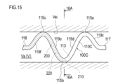
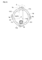
- 15 and 16 schematically show an example of a treatment method using the medical device 10C according to the third modification.
- FIG. 16 is a cross-sectional view of the blood vessel V along the arrows 16A-16A shown in FIG.
- the medical device 10C according to the modified example 3 is configured such that the first portion 115a and the second portion 115b are in point contact with the inner wall Vai of the blood vessel V. Further, the medical device 10C has a third site 115c formed on the proximal end side of the shaft 110C with respect to the second site 115b.
- the portion of the shaft 110C that forms the first portion 115a, the second portion 115b, and the third portion 115c is curved with respect to the axial direction of the shaft 110C. Therefore, the shaft 110C has a zigzag shape that is bent a plurality of times with respect to the axial direction of the shaft 110C.
- the operator can bring each of the first site 115a, the second site 115b, and the third site 115c into contact with the inner wall Vai of the blood vessel V.
- the surgeon can bring the energy radiating portion 210 closer to the inner wall Vai of the blood vessel V by arranging the energy radiating portion 210 at the first site 115a, the second site 115b, and the third site 115c.
- the surgeon performed a portion 119c formed between the first site 115a and the distal site 117, a portion 119d formed between the first site 115a and the second site 115b, and a second site 115b and a third site.
- the portion 119e formed between the 115c and the portion 119f formed between the third portion 115c and the base side portion 118 can be arranged so as not to abut on the inner wall Vai of the blood vessel V.
- the medical device 10C according to the third modification is configured such that the first portion 115a, the second portion 115b, and the third portion 115c formed on the shaft 110C of the guide portion 100C make point contact with the inner wall Vai of the blood vessel V. There is. Therefore, when the first site 115a, the second site 115b, and the third site 115c are brought into contact with the inner wall Vai of the blood vessel V, the burden on the blood vessel V can be reduced.
- the curvature of the portion of the shaft 110C that forms the first portion 115a, the second portion 115b, and the third portion 115c, the axial distance between the respective portions 115a, 115b, and 115c, and the curved portion that forms the zigzag shape are not particularly limited and can be changed arbitrarily.
- FIG. 17 shows the medical device 10D according to the fourth modification.
- 18 and 19 schematically show an example of a treatment method using the medical device 10D according to the fourth modification.
- FIG. 19 is a cross-sectional view of the blood vessel V along the arrows 19A-19A shown in FIG.
- the shaft 110D included in the guide portion 100D of the medical device 10D according to the third modification has an intermediate portion 119 arranged between the first portion 115a and the second portion 115b.
- the intermediate portion 119 is curved from the tip end side of the shaft 110D toward the base end side of the shaft 110D.
- the portion of the shaft 110D on which the first portion 115a is formed and the peripheral portion thereof extend substantially linearly. Further, a portion of the shaft 110D on which the second portion 115b is formed and a peripheral portion thereof extend substantially linearly.
- the operator can bring the first site 115a and the second site 115b into contact with the inner wall Vai of the blood vessel V.
- the operator can bring the energy radiating part 210 close to the inner wall Vai of the blood vessel V.
- the operator can arrange the shaft 110D so that the intermediate portion 119 does not abut on the inner wall Vai of the blood vessel V.
- the first portion 115a and the second portion 115b formed on the shaft 110D extend substantially linearly. Therefore, when the shaft 110D is arranged in the blood vessel V, the operator can bring the first site 115a and the second site 115b into contact with each other in a relatively long range along the extending direction of the blood vessel V. Thereby, the operator can increase the holding force of the shaft 110D with respect to the inner wall Vai of the blood vessel V. In addition, the operator can locally apply energy to the treatment target site S by radiating energy from the energy radiating section 210 arranged at the first site 115a and the second site 115b.
- the axial length of the portion of the shaft 110D forming the first portion 115a and the second portion 115b, the curvature of the intermediate portion 119, and the like are not particularly limited and can be arbitrarily changed. Further, the first portion 115a and the second portion 115b do not have to extend linearly. For example, the first portion 115a and the second portion 115b may not be arranged at positions facing each other.
- FIG. 20 shows an example of a treatment method using the medical device 10E according to the modified example 5.
- blood vessel V (superior mesenteric artery Va) is exemplified as a biological organ to be treated by the medical device 10.
- the biological organ to be treated by the medical device is not limited to blood vessels, and may be the bile duct, trachea, esophagus, urethra, ear and nose lumen, and the like.
- a medical device applies energy to the sympathetic nerve existing in the outer membrane of the renal artery of a patient by radiating energy from an energy radiating part arranged in the renal artery to lower the blood pressure of the patient. It can be configured as a device.
- the medical device can be configured as a device for expanding the bronchus of a patient by radiating energy from an energy radiating unit arranged in the bronchus.
- FIG. 20 shows an example in which the medical device 10E was used for the treatment of pulmonary vein O.
- the first portion 115a and the second portion 115b of the shaft 110E included in the guide portion 100E of the medical device 10E can be brought into contact with the inner wall Oi of the pulmonary vein O.
- the operator can locally apply energy by radiating energy from the energy emitting unit 210 arranged at the first portion 115a and the second portion 115b of the shaft 110E. Thereby, it is possible to treat or recover from a disease such as atrial fibrillation.
- the present invention is not limited to the contents described in the specification, and may be appropriately modified based on the description of the claims. Is possible.
- the specific configuration of the medical device is not limited as long as it includes a guide portion including a shaft on which the first portion and the second portion are formed and a treatment portion configured to be insertable into the lumen of the guide portion.
- the material, shape, size, arrangement, connection structure between members, etc. of each member provided in the guide portion and the treatment portion are not particularly limited as long as the effects of the present invention are exhibited, and can be arbitrarily changed. And can be replaced.
- the medical device can appropriately add arbitrary constituent members and the like which are not particularly described in the specification, and can appropriately omit the additional members described in the specification.
- any procedure not particularly described in the specification can be appropriately added to the treatment method, and the additional procedure described in the specification can be omitted as appropriate.
- the order of the procedures can be appropriately changed as long as the effects of the invention can be exhibited.
Landscapes
- Health & Medical Sciences (AREA)
- Life Sciences & Earth Sciences (AREA)
- Surgery (AREA)
- Engineering & Computer Science (AREA)
- Biomedical Technology (AREA)
- Nuclear Medicine, Radiotherapy & Molecular Imaging (AREA)
- Animal Behavior & Ethology (AREA)
- General Health & Medical Sciences (AREA)
- Public Health (AREA)
- Veterinary Medicine (AREA)
- Physics & Mathematics (AREA)
- Otolaryngology (AREA)
- Heart & Thoracic Surgery (AREA)
- Medical Informatics (AREA)
- Molecular Biology (AREA)
- Electromagnetism (AREA)
- Radiology & Medical Imaging (AREA)
- Plasma & Fusion (AREA)
- Surgical Instruments (AREA)
- Media Introduction/Drainage Providing Device (AREA)
Abstract
Description
図5~図7を参照して、処置対象部位Sについて説明する。図5の符号VRは右腎動脈を示し、符号VLは左腎動脈を示す。また、図5の符号Vaは上腸間膜動脈、符号Vbは腹腔動脈、符号Vcは下腸間膜動脈、符号Vdは大動脈を示す。
図1、図2、図3に示すように、本実施形態に係る医療デバイス10は、ガイド部100と、処置部200と、を有する。
ガイド部100は、内腔113(図9を参照)が形成されたシャフト110を有する。シャフト110は、血管Vに挿入可能に構成されている。
処置部200は、図3、図9に示すように、シャフト110の内腔113に配置された状態において血管Vの外部に位置する周囲神経Naまで到達可能なエネルギーを放射可能であるエネルギー放射部210と、エネルギー放射部210が先端部に配置され、シャフト110の内腔113に挿入された本体部220と、を有する。
次に、医療デバイス10を使用した処置方法の一例を説明する。以下では、血管V(上腸間膜動脈Va)の周囲を走行する周囲神経Naにエネルギーを付与し、周囲神経Naを障害することにより、腸管の蠕動運動を亢進させる手技に医療デバイス10を使用する例を説明する。
図10は、変形例1に係る医療デバイス10Aを示す。
図11は、変形例2に係る医療デバイス10Bを示す。図12及び図13には、変形例2に係る医療デバイス10Bを使用した処置方法の一例を模式的に示す。なお、図13は、図12に示す矢印13A-13Aに沿う血管Vの横断面図である。
図14は、変形例3に係る医療デバイス10Cを示す。図15及び図16には、変形例3に係る医療デバイス10Cを使用した処置方法の一例を模式的に示す。なお、図16は、図15に示す矢印16A-16Aに沿う血管Vの横断面図である。
図17は、変形例4に係る医療デバイス10Dを示す。図18及び図19には、変形例4に係る医療デバイス10Dを使用した処置方法の一例を模式的に示す。なお、図19は、図18に示す矢印19A-19Aに沿う血管Vの横断面図である。
図20は、変形例5に係る医療デバイス10Eを使用した処置方法の一例を示す。
100、100A、100B、100C、100D、100E ガイド部
110、110A、110B、110C、110D、110E シャフト
110a シャフトの先端開口部
113 シャフトの内腔
113a 空間部
114 充填部材
114a ガイドワイヤルーメン
115 螺旋部
115a 第1部位
115b 第2部位
115c 第3部位
116 湾曲部
117 先端側部位
118 基部側部位
119 中間部
120 ハブ
121 操作部
200、200A 処置部
210 エネルギー放射部
220 本体部
230 補助部材
300 コントローラ
A 基準軸
W ガイドワイヤ
Na 周囲神経(血管外神経)
S 処置対象部位
V 血管(生体管腔)
Va 上腸間膜動脈
Vai 内壁
Vb 腹腔動脈
Vc 下腸間膜動脈
Vd 大動脈
O 肺静脈
Oi 肺静脈の内壁
Claims (17)
- 内腔が形成されたシャフトを備え、生体器官に挿入可能なガイド部と、
前記シャフトの前記内腔に配置された状態において、前記生体器官の外部に存在する周囲神経まで到達可能なエネルギーを放射可能であるエネルギー放射部を備える処置部と、を有し、
前記シャフトの先端部には、
前記生体器官の内壁に当接可能に構成された第1部位と、
前記第1部位よりも前記シャフトの基端側に配置され、前記生体器官の内壁の横断面上において前記第1部位とは異なる位置で前記生体器官の内壁に当接可能に構成された第2部位と、が形成されており、
前記処置部は、前記第1部位の少なくとも一部及び前記第2部位の少なくとも一部が前記生体器官の内壁に当接した状態において、前記シャフトの前記内腔を移動可能である、医療デバイス。 - 前記シャフトは、前記第1部位から前記第2部位に至る部分を前記生体器官の内壁に対して連続的に接触させるように構成されている、請求項1に記載の医療デバイス。
- 前記シャフトの先端部には、前記第1部位から前記第2部位に至る部分において螺旋状に延びる螺旋部が形成されている、請求項2に記載の医療デバイス。
- 前記シャフトは、前記第1部位と前記第2部位の各々を前記生体器官の内壁に対して点接触させるように構成されている、請求項1に記載の医療デバイス。
- 前記シャフトの先端部には、前記第1部位と前記第2部位とによりジグザグ形状が形成されている、請求項4に記載の医療デバイス。
- 前記第1部位と前記第2部位の間に配置され、前記シャフトの先端側から前記シャフトの基端側へ向けて湾曲した中間部を有する、請求項1に記載の医療デバイス。
- 前記シャフトは、前記第2部位よりも基端側に位置する湾曲部を有し、
前記湾曲部は、前記湾曲部よりも前記シャフトの先端側に位置する部分を、前記湾曲部よりも前記シャフトの基端側に位置する部分に対して偏向させるように構成されている、請求項1~6のいずれか1項に記載の医療デバイス。 - 前記ガイド部は、前記シャフトと、前記シャフトの基端部に配置されたハブと、を有し、
前記処置部は、前記エネルギー放射部と、前記エネルギー放射部が先端部に配置され、前記シャフトの前記内腔に挿入された本体部と、を有し、
前記ガイド部と前記処置部は一体的に組付けられた状態でカテーテルデバイスを構成している、請求項1~7のいずれか1項に記載の医療デバイス。 - 前記生体器官は、上腸間膜動脈、腹腔動脈、下腸間膜動脈のうちの少なくとも一つの血管であり、
前記血管に配置した前記シャフトの前記内腔に配置した前記エネルギー放射部から放射した前記エネルギーを腸管の神経支配を行う周囲神経に付与して、自律神経の活性を低下させることにより、前記腸管の蠕動運動を亢進させる、請求項1~8のいずれか1項に記載の医療デバイス。 - 前記エネルギー放射部は、マイクロ波または超音波を放射可能に構成されている、請求項1~9のいずれか1項に記載の医療デバイス。
- 内腔が形成されたシャフトを備えるガイド部を生体器官に挿入し、
前記シャフトの先端部に形成された第1部位を前記生体器官の内壁に対して当接させ、かつ、前記第1部位よりも前記シャフトの基端側に形成された第2部位を前記生体器官の前記内壁の横断面上において前記第1部位とは異なる位置に対して当接させ、
前記第1部位及び前記第2部位を前記生体器官の前記内壁に当接させた状態において、エネルギー放射部を備える処置部を前記シャフトの前記内腔に沿って所定の距離だけ移動させ、
前記シャフトの前記内腔に前記エネルギー放射部を配置した状態において、前記エネルギー放射部からエネルギーを放射させて、前記エネルギーを前記生体器官の外部に存在する周囲神経に付与する、処置方法。 - 前記第1部位から前記第2部位に至る部分を前記生体器官の内壁に対して連続的に接触させるように配置した状態で、前記処置部を前記シャフトの前記内腔に沿って所定の距離だけ移動させる、請求項11に記載の処置方法。
- 前記第1部位と前記第2部位の各々を前記生体器官の内壁に対して点接触させるように配置した状態で、前記処置部を前記シャフトの前記内腔に沿って所定の距離だけ移動させる、請求項11に記載の処置方法。
- 前記シャフトは、前記第1部位と前記第2部位の間に配置され、前記シャフトの先端側から前記シャフトの基端側に向かって湾曲した中間部を有し、
前記第1部位と前記第2部位を前記生体器官の内壁に対して当接させた状態で、前記処置部を前記シャフトの前記内腔に沿って所定の距離だけ移動させる、請求項11に記載の処置方法。 - 前記シャフトは、前記第2部位よりも基端側に位置する湾曲部を有し、
前記湾曲部よりも先端側に位置する前記シャフトの一部を前記湾曲部よりも基端側に位置する部分に対して偏向させた状態で、前記生体器官の内壁に当接させた前記第1部位の少なくとも一部及び前記第2部位の少なくとも一部に沿って前記処置部を移動させる、請求項11~14のいずれか1項に記載の処置方法。 - 前記生体器官は、上腸間膜動脈、腹腔動脈、下腸間膜動脈のうちの少なくとも一つの血管であり、
前記血管に配置した前記シャフトの前記内腔に前記エネルギー放射部を配置し、
前記エネルギー放射部から腸管の神経支配を行う周囲神経に対して前記エネルギーを付与して自律神経の活性を低下させることにより、前記腸管の蠕動運動を亢進させる、請求項11~15のいずれか1項に記載の処置方法。 - 前記エネルギー放射部から前記エネルギーとしてマイクロ波または超音波を放射させる、請求項11~16のいずれか1項に記載の処置方法。
Priority Applications (4)
| Application Number | Priority Date | Filing Date | Title |
|---|---|---|---|
| CN202080080867.6A CN114727840B (zh) | 2019-11-20 | 2020-09-29 | 医疗设备 |
| EP20890149.6A EP4062847A4 (en) | 2019-11-20 | 2020-09-29 | MEDICAL DEVICE AND TREATMENT METHOD |
| JP2021507732A JP6924540B1 (ja) | 2019-11-20 | 2020-09-29 | 徐神経用の医療デバイス |
| US17/395,917 US11672597B2 (en) | 2019-11-20 | 2021-08-06 | Medical device and treatment method |
Applications Claiming Priority (2)
| Application Number | Priority Date | Filing Date | Title |
|---|---|---|---|
| PCT/JP2019/045431 WO2021100142A1 (ja) | 2019-11-20 | 2019-11-20 | 医療デバイス、医療器具、および処置方法 |
| JPPCT/JP2019/045431 | 2019-11-20 |
Related Child Applications (1)
| Application Number | Title | Priority Date | Filing Date |
|---|---|---|---|
| US17/395,917 Continuation US11672597B2 (en) | 2019-11-20 | 2021-08-06 | Medical device and treatment method |
Publications (1)
| Publication Number | Publication Date |
|---|---|
| WO2021100323A1 true WO2021100323A1 (ja) | 2021-05-27 |
Family
ID=75980015
Family Applications (2)
| Application Number | Title | Priority Date | Filing Date |
|---|---|---|---|
| PCT/JP2019/045431 Ceased WO2021100142A1 (ja) | 2019-11-20 | 2019-11-20 | 医療デバイス、医療器具、および処置方法 |
| PCT/JP2020/036895 Ceased WO2021100323A1 (ja) | 2019-11-20 | 2020-09-29 | 医療デバイス、および処置方法 |
Family Applications Before (1)
| Application Number | Title | Priority Date | Filing Date |
|---|---|---|---|
| PCT/JP2019/045431 Ceased WO2021100142A1 (ja) | 2019-11-20 | 2019-11-20 | 医療デバイス、医療器具、および処置方法 |
Country Status (5)
| Country | Link |
|---|---|
| US (1) | US11672597B2 (ja) |
| EP (1) | EP4062847A4 (ja) |
| JP (2) | JP6924540B1 (ja) |
| CN (1) | CN114727840B (ja) |
| WO (2) | WO2021100142A1 (ja) |
Families Citing this family (4)
| Publication number | Priority date | Publication date | Assignee | Title |
|---|---|---|---|---|
| WO2013134543A1 (en) | 2012-03-08 | 2013-09-12 | Medtronic Ardian Luxembourg Sarl | Immune system neuromodulation and associated systems and methods |
| JP2017536187A (ja) | 2014-12-03 | 2017-12-07 | メタベンション インコーポレイテッド | 神経または他の組織を調節するためのシステムおよび方法 |
| US10524859B2 (en) | 2016-06-07 | 2020-01-07 | Metavention, Inc. | Therapeutic tissue modulation devices and methods |
| WO2025220105A1 (ja) * | 2024-04-16 | 2025-10-23 | 株式会社Alivas | 医療デバイス |
Citations (5)
| Publication number | Priority date | Publication date | Assignee | Title |
|---|---|---|---|---|
| WO2013134541A2 (en) | 2012-03-08 | 2013-09-12 | Medtronic Ardian Luxembourg Sarl | Gastrointestinal neuromodulation and associated systems and methods |
| JP2013544565A (ja) * | 2010-10-20 | 2013-12-19 | メドトロニック アーディアン ルクセンブルク ソシエテ ア レスポンサビリテ リミテ | 腎神経調節のための拡張可能なメッシュ構造を有するカテーテル器具並びに関連するシステムおよび方法 |
| JP2017123904A (ja) * | 2016-01-12 | 2017-07-20 | 清明 本間 | カテーテルおよびカテーテルシステム |
| JP2017196461A (ja) | 2009-10-30 | 2017-11-02 | リコール メディカル インコーポレイテッドReCor Medical, Inc. | 経皮的超音波腎神経除去による高血圧症を治療するための方法及び装置 |
| JP2019010509A (ja) * | 2017-06-29 | 2019-01-24 | コヴィディエン リミテッド パートナーシップ | 過敏性腸疾患の切除治療のためのシステム及び方法 |
Family Cites Families (11)
| Publication number | Priority date | Publication date | Assignee | Title |
|---|---|---|---|---|
| KR100875136B1 (ko) | 2008-04-16 | 2008-12-22 | 주식회사 다림바이오텍 | 돼지 유래 에스터화 아텔로콜라겐을 이용한 접착성 지혈제및 그 제조방법 |
| JP2014516614A (ja) * | 2011-04-08 | 2014-07-17 | コビディエン エルピー | 自然管腔又は人口管腔のための可撓性マイクロ波カテーテル |
| EP2838459A1 (en) * | 2012-04-16 | 2015-02-25 | Boston Scientific Scimed, Inc. | Helical tubing devices for fluid renal nerve modulation |
| EP3123973A1 (en) * | 2012-08-28 | 2017-02-01 | Boston Scientific Scimed, Inc. | Renal rf ablation system with a movable virtual electrode and related methods of use |
| US9333113B2 (en) * | 2013-03-15 | 2016-05-10 | Abbott Cardiovascular Systems Inc. | System and method for denervation |
| US9848948B2 (en) * | 2013-03-15 | 2017-12-26 | Biosense Webster (Israel) Ltd. | Catheter adapted for use with guide wire for accessing vessels |
| CN104068930A (zh) * | 2014-06-04 | 2014-10-01 | 远见企业有限公司 | 一种具有预先弯折管体的去肾动脉交感神经消融导管 |
| JP6383250B2 (ja) * | 2014-10-28 | 2018-08-29 | テルモ株式会社 | アブレーションカテーテル |
| CN120959691A (zh) * | 2016-02-01 | 2025-11-18 | 美敦力爱尔兰制造无限责任公司 | 用于监测和评估神经调节疗法的系统和方法 |
| US20190000543A1 (en) | 2017-06-29 | 2019-01-03 | Covidien Lp | Systems and methods for ablative treatment of irritable bowel disease |
| US20190000542A1 (en) | 2017-06-29 | 2019-01-03 | Covidien Lp | Systems and methods for ablative treatment of irritable bowel disease |
-
2019
- 2019-11-20 WO PCT/JP2019/045431 patent/WO2021100142A1/ja not_active Ceased
-
2020
- 2020-09-29 EP EP20890149.6A patent/EP4062847A4/en active Pending
- 2020-09-29 CN CN202080080867.6A patent/CN114727840B/zh active Active
- 2020-09-29 JP JP2021507732A patent/JP6924540B1/ja active Active
- 2020-09-29 WO PCT/JP2020/036895 patent/WO2021100323A1/ja not_active Ceased
-
2021
- 2021-07-29 JP JP2021124376A patent/JP7186467B2/ja active Active
- 2021-08-06 US US17/395,917 patent/US11672597B2/en active Active
Patent Citations (5)
| Publication number | Priority date | Publication date | Assignee | Title |
|---|---|---|---|---|
| JP2017196461A (ja) | 2009-10-30 | 2017-11-02 | リコール メディカル インコーポレイテッドReCor Medical, Inc. | 経皮的超音波腎神経除去による高血圧症を治療するための方法及び装置 |
| JP2013544565A (ja) * | 2010-10-20 | 2013-12-19 | メドトロニック アーディアン ルクセンブルク ソシエテ ア レスポンサビリテ リミテ | 腎神経調節のための拡張可能なメッシュ構造を有するカテーテル器具並びに関連するシステムおよび方法 |
| WO2013134541A2 (en) | 2012-03-08 | 2013-09-12 | Medtronic Ardian Luxembourg Sarl | Gastrointestinal neuromodulation and associated systems and methods |
| JP2017123904A (ja) * | 2016-01-12 | 2017-07-20 | 清明 本間 | カテーテルおよびカテーテルシステム |
| JP2019010509A (ja) * | 2017-06-29 | 2019-01-24 | コヴィディエン リミテッド パートナーシップ | 過敏性腸疾患の切除治療のためのシステム及び方法 |
Non-Patent Citations (1)
| Title |
|---|
| See also references of EP4062847A4 |
Also Published As
| Publication number | Publication date |
|---|---|
| WO2021100142A1 (ja) | 2021-05-27 |
| EP4062847A4 (en) | 2023-12-13 |
| CN114727840B (zh) | 2025-04-25 |
| JPWO2021100323A1 (ja) | 2021-11-25 |
| JP6924540B1 (ja) | 2021-08-25 |
| US11672597B2 (en) | 2023-06-13 |
| US20210401497A1 (en) | 2021-12-30 |
| CN114727840A (zh) | 2022-07-08 |
| JP7186467B2 (ja) | 2022-12-09 |
| EP4062847A1 (en) | 2022-09-28 |
| JP2021168985A (ja) | 2021-10-28 |
Similar Documents
| Publication | Publication Date | Title |
|---|---|---|
| JP6924540B1 (ja) | 徐神経用の医療デバイス | |
| US20250255668A1 (en) | Catheter apparatuses, systems, and methods for renal neuromodulation | |
| US11213678B2 (en) | Method of manufacturing a medical device for neuromodulation | |
| JP5827128B2 (ja) | 血管内の熱誘発腎神経変調療法を達成するための装置、システム、および方法 | |
| CN103096826B (zh) | 用于肾神经调节的导管设备、系统和方法 | |
| CN107374723B (zh) | 导管设备 | |
| CN107028651B (zh) | 一种多电极肾动脉射频消融导管 | |
| CN105142553A (zh) | 直接热消融导管 | |
| EP3060152B1 (en) | Catheter apparatuses for modulation of nerves in communication with the pulmonary system and associated systems | |
| JP2017507725A (ja) | 独立した径方向拡張部材を備えたカテーテルならびに関連のデバイス、システム及び方法 | |
| CN117835931A (zh) | 神经调节导管 | |
| US20210007799A1 (en) | Treatment Method and Medical Device | |
| WO2020250417A1 (ja) | カテーテルデバイスおよび処置方法 | |
| WO2021033275A1 (ja) | カテーテルデバイスおよび処置方法 | |
| JP7653210B1 (ja) | 医療デバイス | |
| US20250114143A1 (en) | Catheter system | |
| JP2020031782A (ja) | カテーテルデバイス | |
| WO2019186786A1 (ja) | 処置方法 |
Legal Events
| Date | Code | Title | Description |
|---|---|---|---|
| ENP | Entry into the national phase |
Ref document number: 2021507732 Country of ref document: JP Kind code of ref document: A |
|
| 121 | Ep: the epo has been informed by wipo that ep was designated in this application |
Ref document number: 20890149 Country of ref document: EP Kind code of ref document: A1 |
|
| NENP | Non-entry into the national phase |
Ref country code: DE |
|
| ENP | Entry into the national phase |
Ref document number: 2020890149 Country of ref document: EP Effective date: 20220620 |
|
| WWG | Wipo information: grant in national office |
Ref document number: 202080080867.6 Country of ref document: CN |