WO2021100627A1 - 送信装置、受信装置、および伝送システム - Google Patents
送信装置、受信装置、および伝送システム Download PDFInfo
- Publication number
- WO2021100627A1 WO2021100627A1 PCT/JP2020/042423 JP2020042423W WO2021100627A1 WO 2021100627 A1 WO2021100627 A1 WO 2021100627A1 JP 2020042423 W JP2020042423 W JP 2020042423W WO 2021100627 A1 WO2021100627 A1 WO 2021100627A1
- Authority
- WO
- WIPO (PCT)
- Prior art keywords
- data
- unit
- payload
- header
- pixel
- Prior art date
- Legal status (The legal status is an assumption and is not a legal conclusion. Google has not performed a legal analysis and makes no representation as to the accuracy of the status listed.)
- Ceased
Links
Images





Classifications
-
- H—ELECTRICITY
- H04—ELECTRIC COMMUNICATION TECHNIQUE
- H04N—PICTORIAL COMMUNICATION, e.g. TELEVISION
- H04N23/00—Cameras or camera modules comprising electronic image sensors; Control thereof
- H04N23/60—Control of cameras or camera modules
- H04N23/665—Control of cameras or camera modules involving internal camera communication with the image sensor, e.g. synchronising or multiplexing SSIS control signals
-
- H—ELECTRICITY
- H04—ELECTRIC COMMUNICATION TECHNIQUE
- H04N—PICTORIAL COMMUNICATION, e.g. TELEVISION
- H04N21/00—Selective content distribution, e.g. interactive television or video on demand [VOD]
- H04N21/20—Servers specifically adapted for the distribution of content, e.g. VOD servers; Operations thereof
- H04N21/23—Processing of content or additional data; Elementary server operations; Server middleware
- H04N21/238—Interfacing the downstream path of the transmission network, e.g. adapting the transmission rate of a video stream to network bandwidth; Processing of multiplex streams
- H04N21/23805—Controlling the feeding rate to the network, e.g. by controlling the video pump
-
- H—ELECTRICITY
- H04—ELECTRIC COMMUNICATION TECHNIQUE
- H04N—PICTORIAL COMMUNICATION, e.g. TELEVISION
- H04N21/00—Selective content distribution, e.g. interactive television or video on demand [VOD]
- H04N21/20—Servers specifically adapted for the distribution of content, e.g. VOD servers; Operations thereof
- H04N21/23—Processing of content or additional data; Elementary server operations; Server middleware
- H04N21/24—Monitoring of processes or resources, e.g. monitoring of server load, available bandwidth, upstream requests
-
- H—ELECTRICITY
- H04—ELECTRIC COMMUNICATION TECHNIQUE
- H04L—TRANSMISSION OF DIGITAL INFORMATION, e.g. TELEGRAPHIC COMMUNICATION
- H04L65/00—Network arrangements, protocols or services for supporting real-time applications in data packet communication
- H04L65/60—Network streaming of media packets
- H04L65/75—Media network packet handling
- H04L65/762—Media network packet handling at the source
-
- H—ELECTRICITY
- H04—ELECTRIC COMMUNICATION TECHNIQUE
- H04N—PICTORIAL COMMUNICATION, e.g. TELEVISION
- H04N23/00—Cameras or camera modules comprising electronic image sensors; Control thereof
- H04N23/60—Control of cameras or camera modules
Definitions
- the present disclosure relates to a transmission device for transmitting image data, a receiving device for receiving image data, and a transmission system for transmitting and receiving image data.
- Patent Document 1 discloses a transmission system that generates a packet having a header including control information and a payload including pixel data for one line, and transmits / receives image data using this packet.
- Data ID can be added to the header as an area for storing identification information of pixel data indicating the type of pixel data to be transmitted / received.
- the area for storing the identification information is only the Data ID of the header, the area will be insufficient as the types of pixel data increase, and it may be difficult to reliably transmit the identification information.
- the transmission device is a transmission unit capable of including pixel data for one line constituting one frame of an image in a payload and outputting a plurality of packets having a header added to the payload to a transmission path. And an identification information addition unit that adds identification information of pixel data to at least a part area of the payload.
- the receiving device includes a plurality of packets in which pixel data for one line constituting one frame of an image is included in the payload and a header is added to the payload of the transmitting device via a transmission line.
- the receiving unit includes a receiving unit that can be received from the transmitting unit, and the receiving unit can receive a packet from the transmitting device in which identification information of pixel data is added to at least a part of the payload.
- the transmission system includes a transmitting device and a receiving device, and the transmitting device includes pixel data for one line constituting one frame of an image in a payload and adds a header to the payload. It includes a transmission unit capable of outputting a plurality of such packets to a transmission line, and an identification information addition unit that adds identification information of pixel data to at least a part area of the payload.
- the transmitting device, receiving device, or transmission system it is possible to add the identification information of the pixel data to at least a part of the payload area.
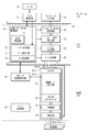
- FIG. 1 shows a first configuration example of the transmission system 1 according to the embodiment of the present disclosure.
- the transmission system 1 shown in FIG. 1 includes a sensor module 11 and a DSP (Digital Signal Processor) 12.
- the sensor module 11 and the DSP 12 are configured by, for example, different LSIs (Large Scale Integrated Circuits) and are provided in the same imaging device having an imaging function, such as a digital camera or a mobile phone.
- LSIs Large Scale Integrated Circuits
- the sensor module 11 has an imaging unit 21 and a transmitting unit 22. Further, the sensor module 11 has a system control unit 51 and a register 53. Further, the sensor module 11 has a frame data input unit 52 (FIG. 6) described later. The system control unit 51 and the register 53 are connected to the image pickup unit 21 and the transmission unit 22.
- the DSP 12 has a receiving unit 31 and an image processing unit 32. Further, the DSP 12 has a register 142 and a system control unit 143. Further, the DSP 12 has a frame data output unit 141 (FIG. 7) described later.
- the register 142 and the system control unit 143 are connected to the reception unit 31 and the image processing unit 32.
- the system control unit 51 and the register 53 in the sensor module 11 and the register 142 and the system control unit 143 in the DSP 12 are connected to each other by the control line 13, so that control data and the like can be communicated between the sensor module 11 and the DSP 12. It has become.
- the image pickup unit 21 has an image pickup element such as CMOS (Complementary Metal Oxide Semiconductor) and performs photoelectric conversion of the light received through the lens. Further, the imaging unit 21 performs A / D conversion of the signal obtained by the photoelectric conversion, and outputs the pixel data constituting the image of one frame to the transmitting unit 22 in order for each pixel data.
- CMOS Complementary Metal Oxide Semiconductor
- the transmission unit 22 allocates the data of each pixel supplied from the image pickup unit 21 to a plurality of transmission lines in the order of supply from, for example, the image pickup unit 21, and transmits the data to the DSP 12 in parallel via the plurality of transmission lines.
- pixel data is transmitted using eight transmission lines.
- the transmission line between the sensor module 11 and the DSP 12 may be a wired transmission line or a wireless transmission line.
- the transmission line between the sensor module 11 and the DSP 12 is appropriately referred to as a lane.
- the receiving unit 31 of the DSP 12 receives the pixel data transmitted from the transmitting unit 22 via the eight lanes, and outputs the data of each pixel to the image processing unit 32 in order.
- the image processing unit 32 generates an image of one frame based on the pixel data supplied from the receiving unit 31, and performs various image processing using the generated image.
- the image data transmitted from the sensor module 11 to the DSP 12 is RAW data, and the image processing unit 32 performs various processes such as image data compression, image display, and image data recording on a recording medium.
- FIG. 2 shows a second configuration example of the transmission system 1 according to the embodiment.
- the imaging unit 21 may be configured to output a plurality of pixel data of different types for the same pixel.
- two different types of pixel data (first pixel data DATA1 and second pixel data DATA2) may be output as data of the same pixel.
- two pixel data having different gains may be output for the same pixel.
- two pixel data may be transmitted in parallel between the transmitting unit 22 and the receiving unit 31.
- Lines 0 to 7 Lines 0 to 3 are assigned as the first divided transmission line (LINK0) for transmitting the first pixel data DATA1
- Lines 4 to 7 are assigned as the second divided transmission line (LINK1) for transmitting the second pixel data DATA2. It may be configured to be assigned as.
- a plurality of lanes are provided by a plurality of divided transmission lines (LINK) for each type of pixel data.
- the configuration may be divided into.
- a plurality of transmission units 22 and a plurality of reception units 31 may be provided.
- the image data of one frame or a plurality of frames captured by one imaging unit 21 is divided and input in parallel to a plurality of transmission units, and the one frame or a plurality of frames input in parallel is input in parallel.
- the image data of the above may be transmitted in parallel to a plurality of receiving units 31.
- the image data of one frame or a plurality of frames received in parallel from the plurality of receiving units 31 may be output to the DSP 12 in parallel.
- the sensor module 11 of the transmission system 1 can be provided with one or a plurality of transmission units 22 for transmitting the image data of one frame or a plurality of frames captured.
- the DSP 12 can be provided with one or a plurality of receiving units 31 for receiving one frame or a plurality of frames of image data transmitted from the sensor module 11 corresponding to the transmitting unit 22 of the sensor module 11. It has become.
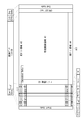
- FIG. 3 shows an example of a frame format used for transmitting one frame of image data between the sensor module 11 and the DSP 12.
- the effective pixel area A1 is an area of effective pixels of a one-frame image captured by the imaging unit 21.
- a margin area A2 in which the number of pixels in the vertical direction is the same as the number of pixels in the vertical direction of the effective pixel area A1 is set.
- a front dummy area A3 is set in which the number of pixels in the horizontal direction is the same as the number of pixels in the horizontal direction of the entire effective pixel area A1 and the margin area A2.
- the embedded data is inserted in the front dummy region A3.
- the Embedded Data includes information on set values related to imaging by the imaging unit 21, such as shutter speed, aperture value, and gain. Embedded Data may be inserted into the rear dummy area A4.
- a rear dummy area A4 is set in which the number of pixels in the horizontal direction is the same as the number of pixels in the horizontal direction of the entire effective pixel area A1 and the margin area A2.
- the image data area A11 is composed of the effective pixel area A1, the margin area A2, the front dummy area A3, and the rear dummy area A4.
- a header is added in front of each line constituting the image data area A11, and a Start Code is added in front of the header.
- a footer is optionally added after each line constituting the image data area A11, and a control code described later such as End Code is added after the footer.
- a control code such as End Code is added after each line constituting the image data area A11.
- the upper band in FIG. 3 shows the structure of the packet used for transmitting the transmission data shown on the lower side. Assuming that the array of pixels in the horizontal direction is a line, the data of the pixels constituting one line of the image data area A11 is stored in the payload of the packet. The transmission of the entire image data in one frame is performed using a number of packets equal to or larger than the number of pixels in the vertical direction of the image data area A11.
- One packet is composed by adding a header and footer to the payload in which pixel data for one line is stored.
- the header contains additional information of pixel data stored in the payload, such as Frame Start, Frame End, Line Valid, Line Number, Reserved, ECC, and the like.
- the header includes an Embedded Line, Data ID as surrounded by a thick line L11. At least Star Code and End Code, which are control codes, are added to each packet.
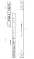
- FIG. 4 shows an example of the header structure of one packet in the frame format shown in FIG.
- FIG. 5 shows an example of the content of the header information in the header structure shown in FIG.
- one packet includes a header and payload data which is pixel data for one line.
- a footer may be added to the packet.
- the header includes header information and Header ECC. Start Code is added to the beginning of each packet, and End Code is added to the end.
- the header information includes Frame Start, Frame End, Line Valid, Line Number, and Reserved.
- the header information further includes an Embedded Line as line information and a Data ID as data identification. The content and amount of each information are shown in FIG.
- Frame Start is 1-bit information indicating the beginning of a frame.
- a value of 1 is set in the Frame Start of the packet header used for transmitting the pixel data of the first line of the image data area A11 in FIG. 3, and the frame of the packet header used for transmitting the pixel data of the other line is set.
- a value of 0 is set for Start.
- Frame End is 1-bit information indicating the end of the frame.
- a value of 1 is set in the Frame End of the packet header containing the pixel data of the end line of the effective pixel area A1 in the payload, and 0 is set in the Frame End of the packet header used for transmitting the pixel data of the other line. The value is set.
- Frame Start and Frame End are frame information which is information about the frame.
- Line Valid is 1-bit information indicating whether or not the pixel data line stored in the payload is a valid pixel line.
- a value of 1 is set in the Line Valid of the packet header used for transmitting the pixel data of the line in the effective pixel area A1, and 0 is set in the Line Valid of the packet header used for transmitting the pixel data of the other line. The value of is set.
- Line Number is 13-bit information representing a line number of a line composed of pixel data stored in a payload.
- Line Valid and Line Number are line information which is information about the line.
- the Embedded Line is 1-bit information indicating whether or not the packet is used for transmission of the line in which the Embedded Data is inserted. For example, a value of 1 is set in the Embedded Line of the packet header used for transmission of the line including Embedded Data, and a value of 0 is set in the Embedded Line of the packet header used for transmission of other lines. .. As described above, the information of the set value related to the imaging is inserted into a predetermined line of the front dummy area A3 and the rear dummy area A4 as Embedded Data.
- the Data ID is P-bit information indicating the number of pixel data stored in the payload.
- the P bit represents a predetermined number of bits of 1 bit or more.
- Reserved is a 31-P bit area for expansion.
- the total amount of data in the header information is 6 bytes.
- the Header ECC arranged following the header information includes a CRC (Cyclic Redundancy Check) code which is a 2-byte error detection code calculated based on the 6-byte header information. Further, the Header ECC includes two pieces of the same information as the 8-byte information which is a set of the header information and the CRC code, following the CRC code.
- CRC Cyclic Redundancy Check
- the header of one packet contains three sets of the same header information and CRC code.
- the total amount of data in the header is 8 bytes for the first set of header information and CRC code, 8 bytes for the second set of header information and CRC code, and the third set of header information and CRC code.
- the total is 24 bytes, including 8 bytes.
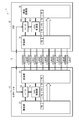
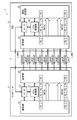
- FIG. 6 shows a configuration example of the transmission unit 22 in the transmission system 1.
- FIG. 7 shows a configuration example of the receiving unit 31 in the transmission system 1.
- the transmitting unit 22 and the receiving unit 31 are composed of a link layer configuration and a physical layer configuration, respectively.
- the configuration shown above the solid line L2 is the configuration of the link layer
- the configuration shown below the solid line L2 is the configuration of the physical layer.
- the configuration shown above the solid line L1 is the configuration of the application layer.
- the application layer includes a system control unit 51, a frame data input unit 52, and a register 53, and a frame data output unit 141, a register 142, and a system control unit 143.
- the frame data input unit 52 is provided in, for example, the image pickup unit 21.
- the frame data output unit 141 is provided in, for example, the image processing unit 32.
- the system control unit 51 communicates with the LINK-TX protocol management unit 61 of the transmission unit 22 and controls the transmission of image data by providing information on the frame format and the like.
- the frame data input unit 52 takes an image in response to an instruction from the user, and supplies the data of each pixel constituting the image obtained by the image to the Pixel to Byte conversion unit 62 of the transmission unit 22.
- the register 53 stores information such as the number of bits and the number of lanes for Pixel to Byte conversion. Image data transmission processing is performed according to the information stored in the register 53.
- the frame data output unit 141 generates and outputs an image of one frame based on the pixel data of each line supplied from the receiving unit 31. Various processes are performed using the image output from the frame data output unit 141.
- the register 142 stores various setting values related to the reception of image data, such as the number of bits for byte-to-Pixel conversion and the number of lanes. Image data reception processing is performed according to the information stored in the register 142.
- the system control unit 143 communicates with the LINK-RX protocol management unit 121 and controls a sequence such as a mode change.
- the transmission unit 22 has a LINK-TX protocol management unit 61, a Pixel to Byte conversion unit 62, a payload ECC insertion unit 63, a packet generation unit 64, and a lane distribution unit as a link layer configuration. 65 is provided.
- the LINK-TX protocol management unit 61 includes a state control unit 71, a header generation unit 72, a data insertion unit 73, and a footer generation unit 74.
- the state control unit 71 of the LINK-TX protocol management unit 61 manages the state of the link layer of the transmission unit 22.
- the header generation unit 72 generates a header to be added to the payload in which pixel data for one line is stored, as shown in FIG. 4, for example, and outputs the header to the packet generation unit 64.
- the header generation unit 72 generates header information according to the control by the system control unit 51.
- the system control unit 51 supplies the header generation unit 72 with information indicating the line number of the pixel data output by the frame data input unit 52 and information indicating the beginning and end of the frame.
- the header generation unit 72 applies the header information to the generation polynomial to calculate the CRC code.
- the CRC code generation polynomial added to the header information is represented by, for example, the following equation (1).
- CRC16 X 16 + X 15 + X 2 +1 ...... (1)
- the header generation unit 72 generates a set of header information and a CRC code by adding a CRC code to the header information, and generates a header by repeatedly arranging three sets of the same header information and a CRC code.
- the header generation unit 72 outputs the generated header to the packet generation unit 64.
- the data insertion unit 73 generates data used for stuffing and outputs it to the Pixel to Byte conversion unit 62 and the lane distribution unit 65.
- the payload stuffing data which is the stuffing data supplied to the Pixel to Byte conversion unit 62, is added to the pixel data after the Pixel to Byte conversion and is used for adjusting the amount of pixel data stored in the payload.
- the lane stuffing data which is the stuffing data supplied to the lane distribution unit 65, is added to the data after lane allocation and used for adjusting the amount of data between lanes.
- the footer generation unit 74 calculates a 32-bit CRC code by appropriately applying payload data to the generation polynomial according to the control by the system control unit 51, and uses the calculated CRC code as a footer in the packet generation unit 64. Output.
- the CRC code generation polynomial added as the footer is represented by, for example, the following equation (2).
- CRC32 X 32 + X 31 + X 4 + X 3 + X + 1 ...... (2)
- the Pixel to Byte conversion unit 62 acquires the pixel data supplied from the frame data input unit 52 and performs a Pixel to Byte conversion that converts the data of each pixel into 1-byte data.
- the pixel value (RGB) of each pixel of the image captured by the imaging unit 21 is represented by the number of bits of any one of 8 bits, 10 bits, 12 bits, 14 bits, and 16 bits.
- the Pixel to Byte conversion unit 62 performs Pixel to Byte conversion for each pixel in order from, for example, the leftmost pixel of the line. Further, the Pixel to Byte conversion unit 62 generates payload data by adding the payload stuffing data supplied from the data insertion unit 73 to the pixel data in byte units obtained by the Pixel to Byte conversion, and inserts the payload ECC. Output to unit 63.
- Pixel to Byte conversion pixel data is grouped into a predetermined number of groups in the order obtained by the conversion.
- processing is performed in parallel for the pixel data at the same position in each group at intervals specified by the clock signal. ..
- the processing of the pixel data proceeds so that the 16 pixel data arranged in each column are processed within the same period.
- the payload of one packet contains one line of pixel data.
- the processing of the pixel data in the effective pixel area A1 of FIG. 3 is described, but the pixel data in other areas such as the margin area A2 is also processed together with the pixel data in the effective pixel area A1.
- Payload stuffing data is 1 byte of data.
- Payload data having such a configuration is supplied from the Pixel to Byte conversion unit 62 to the payload ECC insertion unit 63.
- the payload ECC insertion unit 63 calculates an error correction code used for error correction of the payload data based on the payload data supplied from the Pixel to Byte conversion unit 62, and performs the parity, which is the error correction code obtained by the calculation, as the payload. Insert into the data.
- the error correction code for example, a Reed-Solomon code is used.
- the insertion of the error correction code is an option.
- the payload ECC insertion unit 63 can insert the parity and the footer generation unit 74 can add the footer.
- the payload ECC insertion unit 63 basically, for example, 2-byte parity is generated based on 224 pixel data and inserted in succession to 224 pixel data.
- the payload ECC insertion unit 63 outputs the payload data in which the parity is inserted to the packet generation unit 64.
- the payload data supplied from the Pixel to Byte conversion unit 62 to the payload ECC insertion unit 63 is output to the packet generation unit 64 as it is.
- the packet generation unit 64 generates a packet by adding the header generated by the header generation unit 72 to the payload data supplied from the payload ECC insertion unit 63.
- the packet generation unit 64 also adds the footer to the payload data.
- the packet generation unit 64 outputs packet data, which is data constituting one generated packet, to the lane distribution unit 65.
- packet data consisting of header data and payload data
- packet data consisting of header data, payload data and footer data
- packet data consisting of header data and payload data in which parity is inserted is provided. It will be supplied.
- the packet structure of FIG. 4 is logical, and in the link layer and the physical layer, the data of the packet having the structure of FIG. 4 is processed in byte units.
- the lane distribution unit 65 allocates the packet data supplied from the packet generation unit 64 to each lane used for data transmission among Lanes 0 to 7 in order from the first data.
- the lane distribution unit 65 outputs the packet data assigned to each lane to the physical layer.
- data is transmitted using 8 lanes of Lanes 0 to 7
- the same processing is performed even when the number of lanes used for data transmission is another number.
- the transmission unit 22 is provided with a PHY-TX state control unit 81, a clock generation unit 82, and a signal processing unit 83-0 to 83-N as a physical layer configuration.
- the signal processing unit 83-0 includes a control code insertion unit 91, an 8B10B symbol encoder 92, a synchronization unit 93, and a transmission unit 94.
- the packet data assigned to Lane 0 output from the lane distribution unit 65 is input to the signal processing unit 83-0, and the packet data assigned to Lane 1 is input to the signal processing unit 83-1. Further, the packet data assigned to LaneN is input to the signal processing unit 83-N.
- the physical layer of the transmission unit 22 is provided with the same number of signal processing units 83-0 to 83-N as the number of lanes, and the processing of packet data transmitted using each lane is performed by the signal processing unit. It is performed in parallel in each of 83-0 to 83-N.
- the configuration of the signal processing unit 83-0 will be described, but the signal processing units 83-1 to 83-N also have the same configuration.
- the PHY-TX state control unit 81 controls each unit of the signal processing units 83-0 to 83-N. For example, the timing of each processing performed by the signal processing units 83-0 to 83-N is controlled by the PHY-TX state control unit 81.
- the clock generation unit 82 generates a clock signal and outputs it to each synchronization unit 93 of the signal processing units 83-0 to 83-N.
- the control code insertion unit 91 of the signal processing unit 83-0 adds a control code to the packet data supplied from the lane distribution unit 65.
- the control code is a code represented by one symbol selected from a plurality of types of symbols prepared in advance or by a combination of a plurality of types of symbols.
- Each symbol inserted by the control code insertion unit 91 is 8-bit data.
- 8B10B conversion By performing 8B10B conversion in the circuit in the subsequent stage, one symbol inserted by the control code insertion unit 91 becomes 10-bit data.
- 10B8B conversion is performed on the received data as described later, but each symbol before 10B8B conversion included in the received data is 10-bit data, and each symbol after 10B8B conversion is It becomes 8-bit data.
- the control code includes the Start Code, End Code, etc. shown in FIG. Further, the control code includes an Idle Code, a Pad Code, a Sync Code, a Desk Code, and a Standby Code.
- the control code insertion unit 91 outputs packet data to which the control code is added to the 8B10B symbol encoder 92.
- the 8B10B symbol encoder 92 performs 8B10B conversion on the packet data (packet data to which the control code is added) supplied from the control code insertion unit 91, and converts the packet data into 10-bit unit data into the synchronization unit 93. Output.
- the synchronization unit 93 outputs each bit of the packet data supplied from the 8B10B symbol encoder 92 to the transmission unit 94 according to the clock signal generated by the clock generation unit 82.
- the transmission unit 94 transmits the packet data supplied from the synchronization unit 93 to the reception unit 31 via the transmission line constituting Lane 0.
- packet data is transmitted to the receiving unit 31 using the transmission lines constituting Lanes 1 to 7.
- the receiving unit 31 is provided with the PHY-RX state control unit 101 and the signal processing units 102-0 to 102-N as a physical layer configuration.
- the signal processing unit 102-0 includes a receiving unit 111, a clock generation unit 112, a synchronization unit 113, a symbol synchronization unit 114, a 10B8B symbol decoder 115, a skew correction unit 116, and a control code removing unit 117.
- the packet data transmitted via the transmission line constituting Lane0 is input to the signal processing unit 102-0, and the packet data transmitted via the transmission line constituting Line1 is input to the signal processing unit 102-1. Will be done. Further, the packet data transmitted via the transmission line constituting the Lane N is input to the signal processing unit 102-N.
- the physical layer of the receiving unit 31 is provided with as many signal processing units 102-0 to 102-N as the number of lanes, and the processing of packet data transmitted using each lane is a signal. It is performed in parallel in each of the processing units 102-0 to 102-N.
- the configuration of the signal processing unit 102-0 will be described, but the signal processing units 102-1 to 102-N also have the same configuration.
- the receiving unit 111 receives a signal representing the packet data transmitted from the transmitting unit 22 via the transmission line constituting Lane 0, and outputs the signal to the clock generating unit 112.
- the clock generation unit 112 performs bit synchronization by detecting the edge of the signal supplied from the reception unit 111, and generates a clock signal based on the edge detection cycle.
- the clock generation unit 112 outputs the signal supplied from the reception unit 111 to the synchronization unit 113 together with the clock signal.
- the synchronization unit 113 samples the signal received by the reception unit 111 according to the clock signal generated by the clock generation unit 112, and outputs the packet data obtained by the sampling to the symbol synchronization unit 114.
- the clock generation unit 112 and the synchronization unit 113 realize the function of CDR (Clock Data Recovery).
- the symbol synchronization unit 114 synchronizes the symbols by detecting the control code included in the packet data or by detecting some symbols included in the control code. For example, the symbol synchronization unit 114 detects the K28.5 symbol included in the Start Code, End Code, and Desk Code, and synchronizes the symbols. The symbol synchronization unit 114 outputs packet data in units of 10 bits representing each symbol to the 10B8B symbol decoder 115.
- the symbol synchronization unit 114 synchronizes the symbols by detecting the boundaries of the symbols included in the Sync Code that are repeatedly transmitted from the transmission unit 22 in the training mode before the transmission of the packet data is started.
- the 10B8B symbol decoder 115 performs 10B8B conversion on the packet data in units of 10 bits supplied from the symbol synchronization unit 114, and outputs the packet data converted into data in units of 8 bits to the skew correction unit 116.
- the skew correction unit 116 detects the Desk Code from the packet data supplied from the 10B8B symbol decoder 115. Information on the detection timing of the Desk Code by the skew correction unit 116 is supplied to the PHY-RX state control unit 101.
- the skew correction unit 116 corrects the Data Skew between lanes by matching the timing of the Desk Code with the timing represented by the information supplied from the PHY-RX state control unit 101. From the PHY-RX state control unit 101, information indicating the latest timing among the timings of the Desk Code detected in each of the signal processing units 102-0 to 102-N is supplied.
- the skew correction unit 116 outputs the packet data corrected for Data Skew to the control code removal unit 117.
- the control code removing unit 117 removes the control code added to the packet data, and outputs the data between the Start Code and the End Code to the link layer as packet data.
- the PHY-RX state control unit 101 controls each unit of the signal processing units 102-0 to 102-N to correct Data Skew between lanes. Further, when a transmission error occurs in a predetermined lane and the control code is lost, the PHY-RX state control unit 101 adds a control code transmitted in another lane in place of the lost control code. By doing so, the error correction of the control code is performed.
- the receiving unit 31 has a LINK-RX protocol management unit 121, a lane integration unit 122, a packet separation unit 123, a payload error correction unit 124, and a Byte to Pixel conversion unit as a link layer configuration. 125 is provided.
- the LINK-RX protocol management unit 121 includes a state control unit 131, a header error correction unit 132, a data removal unit 133, and a footer error detection unit 134.
- the lane integration unit 122 integrates the packet data supplied from the signal processing units 102-0 to 102-N of the physical layer by rearranging the packet data in the reverse order of the distribution order to each lane by the lane distribution unit 65 of the transmission unit 22. To do.
- the lane stuffing data is removed by the lane integration unit 122 according to the control by the data removal unit 133.
- the lane integration unit 122 outputs the integrated packet data to the packet separation unit 123.
- the packet separation unit 123 separates the packet data for one packet integrated by the lane integration unit 122 into the packet data constituting the header data and the packet data constituting the payload data.
- the packet separation unit 123 outputs the header data to the header error correction unit 132 and outputs the payload data to the payload error correction unit 124.
- the packet separation unit 123 converts the data for one packet into the packet data constituting the header data, the packet data constituting the payload data, and the packet data constituting the footer data. To separate.
- the packet separation unit 123 outputs the header data to the header error correction unit 132 and outputs the payload data to the payload error correction unit 124. Further, the packet separation unit 123 outputs the footer data to the footer error detection unit 134.
- the payload error correction unit 124 detects an error in the payload data by performing an error correction operation based on the parity, and corrects the detected error. I do.
- the payload error correction unit 124 outputs the pixel data after error correction obtained by performing error correction for each Basic Block and Extra Block to the Byte to Pixel conversion unit 125.
- the payload data supplied from the packet separation unit 123 is output to the Byte to Pixel conversion unit 125 as it is.
- the Byte to Pixel conversion unit 125 removes the payload stuffing data included in the payload data supplied from the payload error correction unit 124 according to the control by the data removal unit 133.
- the Byte to Pixel conversion unit 125 converts the data of each pixel in byte units obtained by removing the payload stuffing data into pixel data in 8-bit, 10-bit, 12-bit, 14-bit, or 16-bit units. Perform Byte to Pixel conversion. In the Byte to Byte conversion unit 125, the conversion opposite to the Pixel to Byte conversion by the Pixel to Byte conversion unit 62 of the transmission unit 22 is performed.
- the Byte to Pixel conversion unit 125 outputs 8-bit, 10-bit, 12-bit, 14-bit, or 16-bit unit pixel data obtained by the Byte to Pixel conversion to the frame data output unit 141.
- each line of effective pixels specified by the Line Valid of the header information is generated based on the pixel data obtained by the Byte to Pixel conversion unit 125, and each line is generated according to the Line Number of the header information. By arranging the lines, a one-frame image is generated.
- the state control unit 131 of the LINK-RX protocol management unit 121 manages the state of the link layer of the reception unit 31.
- the header error correction unit 132 acquires three sets of header information and CRC code based on the header data supplied from the packet separation unit 123.
- the header error correction unit 132 uses the same set of CRC codes as the header information to perform an error detection operation, which is an operation for detecting an error in the header information, for each set of the header information and the CRC code. Do.
- the header error correction unit 132 estimates the correct header information based on at least one of the error detection result of the header information of each set and the comparison result of the data obtained by the error detection calculation, and is correct.
- the header information estimated to be and the decoding result are output.
- the data obtained by the error detection operation is a value obtained by applying a CRC generation polynomial to the header information.
- the decoding result is information indicating success or failure of decoding.
- the three sets of header information and CRC code are set as set 1, set 2, and set 3, respectively.
- the header error correction unit 132 determines whether or not there is an error in the header information of the set 1 (error detection result) by the error detection calculation for the set 1, and the data obtained by the error detection calculation. Acquire data 1. Further, the header error correction unit 132 acquires whether or not there is an error in the header information of the set 2 and the data 2 which is the data obtained by the error detection calculation by the error detection calculation for the set 2. The header error correction unit 132 acquires whether or not there is an error in the header information of the set 3 and the data 3 which is the data obtained by the error detection calculation by the error detection calculation for the set 3.
- the header error correction unit 132 determines whether or not the data 1 and the data 2 match, whether or not the data 2 and the data 3 match, and whether or not the data 3 and the data 1 match, respectively.
- the header error correction unit 132 does not detect an error by any of the error detection operations for the set 1, the set 2, and the set 3, and all the comparison results of the data obtained by the error detection operation match. If so, information indicating successful decoding is selected as the decoding result. Further, the header error correction unit 132 estimates that all the header information is correct, and selects any one of the header information of the set 1, the header information of the set 2, and the header information of the set 3 as output information.
- the header error correction unit 132 selects the information indicating the success of the decoding as the decoding result and determines that the header information of the set 1 is correct. Guess and select the header information of set 1 as output information.
- the header error correction unit 132 selects the information indicating the success of the decoding as the decoding result, and determines that the header information of the set 2 is correct. Guess and select the header information of group 2 as output information.
- the header error correction unit 132 selects the information indicating the success of the decoding as the decoding result and estimates that the header information of the set 3 is correct. , Select the header information of group 3 as output information.
- the header error correction unit 132 outputs the decoding result and output information selected as described above to the register 142 and stores them. In this way, the error correction of the header information by the header error correction unit 132 is performed by detecting the header information without an error from a plurality of header information using the CRC code and outputting the detected header information. It is said.
- the data removal unit 133 controls the lane integration unit 122 to remove the lane stuffing data, and controls the Byte to Pixel conversion unit 125 to remove the payload stuffing data.
- the footer error detection unit 134 acquires the CRC code stored in the footer based on the footer data supplied from the packet separation unit 123.
- the footer error detection unit 134 performs an error detection operation using the acquired CRC code to detect an error in the payload data.
- the footer error detection unit 134 outputs an error detection result and stores it in the register 142.
- the imaging unit 21 of the sensor module 11 performs imaging when, for example, a shutter button provided on the imaging device is pressed to instruct the start of imaging.
- the frame data input unit 52 (FIG. 6) of the image pickup unit 21 outputs the pixel data constituting the image of one frame obtained by the image pickup to the transmission unit 22 in order of the pixel data.
- the data transmission process by the transmission unit 22 generates a packet in which pixel data for one line is stored in the payload, and the packet data constituting the packet is transmitted to the reception unit 31.
- the receiving unit 31 performs data receiving processing. By the data reception process, the packet data transmitted from the transmission unit 22 is received, and the pixel data stored in the payload is output to the image processing unit 32.
- the data transmission process performed by the transmission unit 22 and the data reception process performed by the reception unit 31 are alternately performed for one line of pixel data. That is, when the pixel data of a certain line is transmitted by the data transmission process, the data reception process is performed, and when the pixel data of one line is received by the data reception process, the pixel data of the next one line is targeted. Data transmission processing is performed.
- the data transmission process by the transmission unit 22 and the data reception process by the reception unit 31 may be performed in parallel in time as appropriate.
- the frame data output unit 141 of the image processing unit 32 When the transmission / reception of pixel data of all the lines constituting the image of one frame is completed, the frame data output unit 141 of the image processing unit 32 generates an image of one frame based on the pixel data supplied from the receiving unit 31. To do.
- the identification information includes ROI (Region of Interest), a type of transmission line for transmitting pixel data (LINK), and the like.
- the area for storing the Data ID can be expanded to some extent by using the Reserved area of the header.
- the types of pixel data and the like have increased, there is a possibility that the identification information cannot be accommodated only in this header area including the Reserved area.
- FIG. 8 shows the first example of the extended storage destination of the Data ID.
- the Data ID can be added to, for example, the embedded Data area.
- FIG. 8 shows an example in which the front dummy area A3 has the embedded data area
- the embedded data area may be inserted in the rear dummy area A4.
- the packet generation unit 64 generates, for example, a packet in which the Data ID is added to the embedded Data area.
- FIG. 9 shows a second example of the extended storage destination of the Data ID.
- the Data ID can be added to a part of the payload including pixel data, for example.
- the packet generation unit 64 generates, for example, a packet in which the Data ID is added to a part of the payload area including the pixel data.
- the Reserved area in the header may be used as an area or the like indicating the extended storage destination of the Data ID.
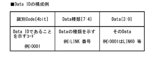
- FIG. 10 shows a configuration example of Data ID.
- the Data ID includes, for example, an identification Code, a Data type, and Data.
- the identification Code is set to 4 bits with expandability in consideration of adding data other than Data ID.
- the Data ID is a code indicating that the Data ID is a Data ID, and is a value such as "0001".
- the Data type indicates the Data type of the Data ID.
- the Data type indicates, for example, a LINK number or the like.
- Data indicates Data of Data ID. Data indicates, for example, that if it is "0001", it is LINK0.
- 11 to 12 show an example of data configuration when the Data ID is added to the embedded Data area.
- FIG. 11 shows the first example of the data configuration example when the Data ID is added to the Embedded Data.
- FIG. 11 shows a configuration example of Data ID when, for example, two types of pixel data are distributed to LINK0 and LINK1 respectively.
- the value of the identification Code is "0001", which indicates that it is a Data ID.
- the value of the Data type is "0001”, and it is shown that Data is a LINK number.
- the value of Data is "0001", which indicates that the output is from LINK0.
- FIG. 12 shows a second example of a data configuration example when a Data ID is added to the Embedded Data.
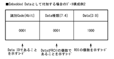
- FIG. 12 shows, for example, a configuration example of Data ID indicating the number of ROIs.
- the value of the identification Code is "0001", which indicates that it is a Data ID.
- the value of the Data type is "0010”, and it is shown that Data is the number of ROIs.
- the value of Data is "1000", and the number of ROIs is shown.
- FIGS. 13 to 15 show an example of data configuration when a Data ID is added for each line.
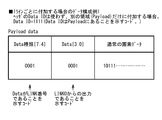
- FIG. 13 shows the first example of the data configuration example when the Data ID is added to the payload.
- FIG. 13 shows an example in which the Data ID of the header is not used and the Data ID is added only to another area (payload).
- the value of the Data ID in the header is "1111", indicating that the Data ID is in the payload.
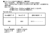
- the payload includes a Data type, Data, and ordinary pixel data for one line.
- the value of the Data type is "0001”, and it is shown that Data is a LINK number. Further, the value of Data is "0001", which indicates that the output is from LINK0.
- FIG. 14 shows a second example of a data configuration example when a Data ID is added to the payload.
- FIG. 14 shows a first example in which the Data ID of the header is used together and the Data ID is added to another area (paloader).
- the payload includes Data type, Data, and normal pixel data for one line.
- the value of the Data type is "0001", and it is shown that Data is a LINK number. Further, the value of Data is "0001", which indicates that the output is from LINK0.
- FIG. 15 shows a third example of a data configuration example when a Data ID is added to the payload.
- FIG. 15 shows a second example in which the Data ID of the header is used together and the Data ID is added to another area (paloader).
- the Reserved area of the header is used to show that the Data ID is also present in the payload.
- one bit in the Reserved area is used as an extension bit of Data ID. For example, when the value of Reserved is 1, and when it is 0, the following is shown. Case 1: Indicates that the Data ID is also in the payload area. 0: Indicates that the Data ID is only in the header area.
- the payload includes Data type, Data, and normal pixel data for one line.
- the value of the Data type is "0001", and it is shown that Data is a LINK number. Further, the value of Data is "0001", which indicates that the output is from LINK0.
- FIG. 16 shows a specific example of the identification information represented by the Data ID.
- the Data type includes, for example, Gain, exposure time, ROIID, ROI position information, AD bit number, pixel type information, shutter speed, pixel position, and the presence or absence of ECC.
- the Data When the Data type is Gain, the Data includes the Gain setting value.
- Examples of Data description examples may be 0 [dB], 6 [dB], 1 [times], 2 [times], and the like.
- the Data When the Data type is an exposure time, the Data includes a value indicating exposure time information. As an example of Data description, it may be, for example, 1 [ms].
- the Data When the Data type is ROI ID, the Data includes the area ID number. Examples of Data description examples may be, for example, 1, 2, 3, ....
- the Data When the Data type is ROI position information, the Data includes the upper left coordinates and the like. As an example of Data description, for example, the X coordinate of the upper left pixel may be used.
- the Data type is the number of AD bits
- the Data includes the number of bits.
- Examples of Data description examples may be, for example, 10 [bit], 12 [bit], and the like.
- the Data type is pixel type information
- the Data When the Data type is shutter speed, the Data includes the frame rate. Examples of Data description examples may be 60 [fps], 120 [fps], and the like.
- the identification information of the pixel data can be added to at least a part of the payload. It is possible to reliably transmit the identification information of the pixel data.
- the improvement example of the transmission system 1 according to the embodiment even when it becomes difficult to add the identification information only in the Data ID area of the header due to the increase in the types of pixel data and the like. It is possible to reliably transmit the identification information of the pixel data.
- the present technology may have the following configuration.
- the identification information of the pixel data can be added to at least a part of the payload, so that the identification information of the pixel data can be reliably transmitted. It will be possible.
- a transmitter that includes pixel data for one line constituting an image of one frame in a payload and can output a plurality of packets with a header added to the payload to a transmission line.
- a transmission device including an identification information addition unit that adds identification information of the pixel data to at least a part area of the payload.
- some packets are packets that include a dummy area in the payload instead of the pixel data.
- the identification information addition unit adds data indicating the identification information to the dummy area.
- the identification information addition unit adds data indicating the identification information for a plurality of lines to the dummy area.
- the transmission device adds identification information for each line to a part of a part of the payload of each of the plurality of packets.
- the identification information addition unit adds the identification information to the header and at least a part of the payload.
- the identification information addition unit adds information about an area to which the identification information is added to the header.
- the payload includes pixel data for one line constituting one frame of an image, and a receiver having a header added to the payload can be received from a transmitter of a transmitter via a transmission line.
- the receiving unit is a receiving device capable of receiving a packet in which identification information of the pixel data is added to at least a part of the payload area from the transmitting device.
- the transmitter is A transmitter that includes pixel data for one line constituting an image of one frame in a payload and can output a plurality of packets with a header added to the payload to a transmission line.
- the receiving device is A receiving unit capable of receiving the plurality of packets from the transmitting unit of the transmitting device via the transmission line is provided.
- the transmission system according to (8) above, wherein the receiving unit can receive a packet in which identification information of the pixel data is added to at least a part area of the payload from the transmitting device.
Landscapes
- Engineering & Computer Science (AREA)
- Multimedia (AREA)
- Signal Processing (AREA)
- Data Exchanges In Wide-Area Networks (AREA)
- Studio Devices (AREA)
- Two-Way Televisions, Distribution Of Moving Picture Or The Like (AREA)
Abstract
本開示の送信装置は、1フレームの画像を構成する1ライン分の画素データをペイロードに含み、ペイロードにヘッダを付加した複数のパケットを伝送路へと出力可能な送信部と、画素データの識別情報を、少なくともペイロードの一部の領域に付加する識別情報付加部とを備える。
Description
本開示は、画像データの送信を行う送信装置、画像データの受信を行う受信装置、および画像データの送受信を行う伝送システムに関する。
伝送システムには、複数ライン分の画素データを含む画像データを送受信するものがある。特許文献1には、制御情報を含むヘッダと、1ライン分の画素データを含むペイロードとを有するパケットを生成し、このパケットを用いて画像データを送受信する伝送システムが開示されている。特許文献1に記載の技術では、送受信される画素データの種類等を示す画素データの識別情報を格納する領域としてData IDをヘッダに付加することが可能となっている。
識別情報を格納する領域がヘッダのData IDのみでは、画素データの種類が増加するに伴い、領域が不足し、識別情報を確実に伝送することが困難になる可能性がある。
画素データの識別情報を確実に伝送することが可能となる送信装置、受信装置、および伝送システムを提供することが望ましい。
本開示の一実施の形態に係る送信装置は、1フレームの画像を構成する1ライン分の画素データをペイロードに含み、ペイロードにヘッダを付加した複数のパケットを伝送路へと出力可能な送信部と、画素データの識別情報を、少なくともペイロードの一部の領域に付加する識別情報付加部とを備える。
本開示の一実施の形態に係る受信装置は、1フレームの画像を構成する1ライン分の画素データをペイロードに含み、ペイロードにヘッダを付加した複数のパケットを、伝送路を介して送信装置の送信部から受信可能な受信部を備え、受信部は、少なくともペイロードの一部の領域に画素データの識別情報が付加されたパケットを、送信装置から受信可能である。
本開示の一実施の形態に係る伝送システムは、送信装置と、受信装置とを含み、送信装置は、1フレームの画像を構成する1ライン分の画素データをペイロードに含み、ペイロードにヘッダを付加した複数のパケットを伝送路へと出力可能な送信部と、画素データの識別情報を、少なくともペイロードの一部の領域に付加する識別情報付加部とを備える。
本開示の一実施の形態に係る送信装置、受信装置、または伝送システムでは、画素データの識別情報を、少なくともペイロードの一部の領域に付加することが可能となる。
以下、本開示の実施の形態について図面を参照して詳細に説明する。なお、説明は以下の順序で行う。
1.一実施の形態
1.1 一実施の形態に係る伝送システムの構成および動作(図1~図7)
1.2 一実施の形態に係る伝送システムの改善例(図8~図16)
1.3 効果
2.その他の実施の形態
1.一実施の形態
1.1 一実施の形態に係る伝送システムの構成および動作(図1~図7)
1.2 一実施の形態に係る伝送システムの改善例(図8~図16)
1.3 効果
2.その他の実施の形態
<1.一実施の形態>
[1.1 一実施の形態に係る伝送システムの構成および動作]
[伝送システムの構成例]
図1は、本開示の一実施の形態に係る伝送システム1の第1の構成例を示している。
[1.1 一実施の形態に係る伝送システムの構成および動作]
[伝送システムの構成例]
図1は、本開示の一実施の形態に係る伝送システム1の第1の構成例を示している。
図1に示した伝送システム1は、センサモジュール11とDSP(Digital Signal Processor)12とを備えている。センサモジュール11とDSP12は、例えば、それぞれ異なるLSI(Large Scale Integrated Circuit)により構成され、デジタルカメラや携帯電話機などの、撮像機能を有する同じ撮像装置内に設けられる。
センサモジュール11は、撮像部21と送信部22とを有している。また、センサモジュール11は、システム制御部51と、レジスタ53とを有している。また、センサモジュール11は、後述するフレームデータ入力部52(図6)を有している。システム制御部51とレジスタ53は、撮像部21と送信部22とに接続されている。
DSP12は、受信部31と画像処理部32とを有している。また、DSP12は、レジスタ142と、システム制御部143とを有している。また、DSP12は、後述するフレームデータ出力部141(図7)を有している。レジスタ142とシステム制御部143は、受信部31と画像処理部32とに接続されている。
センサモジュール11におけるシステム制御部51およびレジスタ53と、DSP12におけるレジスタ142およびシステム制御部143は、制御線13により互いに接続され、センサモジュール11とDSP12との間で、制御データ等の通信が可能となっている。
撮像部21は、CMOS(Complementary Metal Oxide Semiconductor)などの撮像素子を有し、レンズを介して受光した光の光電変換を行う。また、撮像部21は、光電変換によって得られた信号のA/D変換などを行い、1フレームの画像を構成する画素データを、1画素のデータずつ順に送信部22に出力する。
送信部22は、撮像部21から供給された各画素のデータを、例えば撮像部21から供給された順に複数の伝送路に割り当て、複数の伝送路を介して並列にDSP12に送信する。図1の例においては、8本の伝送路を用いて画素データの伝送が行われている。センサモジュール11とDSP12の間の伝送路は有線の伝送路であってもよいし、無線の伝送路であってもよい。以下、適宜、センサモジュール11とDSP12の間の伝送路をレーン(Lane)という。
DSP12の受信部31は、8本のレーンを介して送信部22から伝送されてきた画素データを受信し、各画素のデータを順に画像処理部32に出力する。
画像処理部32は、受信部31から供給された画素データに基づいて1フレームの画像を生成し、生成した画像を用いて各種の画像処理を行う。センサモジュール11からDSP12に伝送される画像データはRAWデータであり、画像処理部32においては、画像データの圧縮、画像の表示、記録媒体に対する画像データの記録などの各種の処理が行われる。
図2は、一実施の形態に係る伝送システム1の第2の構成例を示している。
撮像部21からは、同一画素につき、互いに種類の異なる複数の画素データが出力されるように構成されてもよい。例えば図2に示したように、同一画素のデータとして、種類の異なる2つの画素データ(第1画素データDATA1、第2画素データDATA2)が出力されるように構成されてもよい。例えば、同一画素について、ゲインの異なる2つの画素データが出力されるように構成されてもよい。この場合、送信部22と受信部31との間で、例えば2つの画素データを並列的に伝送するように構成されてもよい。例えば、Lane0~7のうちLane0~3を第1画素データDATA1を伝送する第1分割伝送路(LINK0)として割り当て、Lane4~7を第2画素データDATA2を伝送する第2分割伝送路(LINK1)として割り当てるように構成してもよい。このように、送信部22と受信部31との間で、例えば種類の異なる画素データを並列的に伝送するために、複数のレーンを、画素データの種類ごとの複数の分割伝送路(LINK)に分割した構成にしてもよい。
なお、伝送システム1において、送信部22と受信部31とが、それぞれ複数設けられていてもよい。この場合、例えば、1つの撮像部21で撮像された1フレームまたは複数フレームの画像データを分割して、複数の送信部に並列的に入力し、その並列的に入力された1フレームまたは複数フレームの画像データを、複数の受信部31に並列的に送信するようにしてもよい。そして、並列的に受信した複数の受信部31からの1フレームまたは複数フレームの画像データを並列的にDSP12に出力するようにしてもよい。
以上のように、伝送システム1のセンサモジュール11には、撮像された1フレームまたは複数フレームの画像データを伝送する送信部22を1つまたは複数設けることが可能となっている。一方、DSP12には、センサモジュール11の送信部22に対応して、センサモジュール11から伝送されてきた1フレームまたは複数フレームの画像データを受信する受信部31が1つまたは複数設けることが可能となっている。
以下、センサモジュール11に1つの送信部22が設けられ、DSP12に1つの受信部31が設けられる図1の伝送システム1におけるデータ伝送を基本にして説明する。複数の送信部22のそれぞれと複数の受信部31のそれぞれとの間においても同様にしてデータ伝送が行われる。
[フレームフォーマット]
図3は、センサモジュール11とDSP12との間で1フレームの画像データを伝送するのに用いられるフレームフォーマットの一例を示している。
図3は、センサモジュール11とDSP12との間で1フレームの画像データを伝送するのに用いられるフレームフォーマットの一例を示している。
有効画素領域A1は、撮像部21により撮像された1フレームの画像の有効画素の領域である。有効画素領域A1の左側には、垂直方向の画素数が有効画素領域A1の垂直方向の画素数と同じであるマージン領域A2が設定される。
有効画素領域A1の上側には、水平方向の画素数が、有効画素領域A1とマージン領域A2全体の水平方向の画素数と同じである前ダミー領域A3が設定される。図3の例においては、前ダミー領域A3にはEmbedded Dataが挿入されている。Embedded Dataは、シャッタスピード、絞り値、ゲインなどの、撮像部21による撮像に関する設定値の情報が含まれる。後ダミー領域A4にEmbedded Dataが挿入されることもある。
有効画素領域A1の下側には、水平方向の画素数が、有効画素領域A1とマージン領域A2全体の水平方向の画素数と同じである後ダミー領域A4が設定される。
有効画素領域A1、マージン領域A2、前ダミー領域A3、および後ダミー領域A4から画像データ領域A11が構成される。
画像データ領域A11を構成する各ラインの前にはヘッダが付加され、ヘッダの前にはStart Codeが付加される。また、画像データ領域A11を構成する各ラインの後ろにはフッタがオプションで付加され、フッタの後ろにはEnd Codeなどの後述する制御コードが付加される。フッタが付加されない場合、画像データ領域A11を構成する各ラインの後ろにEnd Codeなどの制御コードが付加される。
撮像部21により撮像された1フレームの画像をセンサモジュール11からDSP12に伝送する毎に、図3に示すフォーマットのデータ全体が伝送データとして伝送される。
図3の上側の帯は下側に示す伝送データの伝送に用いられるパケットの構造を示している。水平方向の画素の並びをラインとすると、パケットのペイロードには、画像データ領域A11の1ラインを構成する画素のデータが格納される。1フレームの画像データ全体の伝送は、画像データ領域A11の垂直方向の画素数以上の数のパケットを用いて行われることになる。
1ライン分の画素データが格納されたペイロードに、ヘッダとフッタが付加されることによって1パケットが構成される。後に詳述するように、ヘッダには、Frame Start,Frame End,Line Valid,Line Number,Reserved,ECCなどの、ペイロードに格納されている画素データの付加的な情報が含まれる。また、ヘッダには、太線L11で囲んだように、Embedded Line,Data IDが含まれる。各パケットには、制御コードであるStart CodeとEnd Codeが少なくとも付加される。
このように、1フレームの画像を構成する画素データをライン毎に伝送するフォーマットを採用することによって、ヘッダ等の付加的な情報やStart Code, End Codeなどの制御コードをライン毎のブランキング期間中に伝送することが可能になる。
図4は、図3に示したフレームフォーマットの1パケットのヘッダ構造の一例を示している。図5は、図4に示したヘッダ構造におけるヘッダ情報の内容の一例を示している。
上述したように、1つのパケットは、ヘッダと、1ライン分の画素データであるペイロードデータとを含む。パケットにはフッタが付加されることもある。ヘッダは、ヘッダ情報とHeader ECCとを含む。各パケットの先頭にはStart Codeが付加され、後ろにはEnd Codeが付加される。
ヘッダ情報には、Frame Start,Frame End,Line Valid,Line Number,Reservedが含まれる。ヘッダ情報には、さらに、ライン情報としてのEmbedded Line、およびデータ識別としてのData IDが含まれる。各情報の内容と情報量を図5に示す。
Frame Startは、フレームの先頭を示す1ビットの情報である。図3の画像データ領域A11の1ライン目の画素データの伝送に用いられるパケットのヘッダのFrame Startには1の値が設定され、他のラインの画素データの伝送に用いられるパケットのヘッダのFrame Startには0の値が設定される。
Frame Endは、フレームの終端を示す1ビットの情報である。有効画素領域A1の終端ラインの画素データをペイロードに含むパケットのヘッダのFrame Endには1の値が設定され、他のラインの画素データの伝送に用いられるパケットのヘッダのFrame Endには0の値が設定される。
Frame StartとFrame Endが、フレームに関する情報であるフレーム情報となる。
Line Validは、ペイロードに格納されている画素データのラインが有効画素のラインであるのか否かを表す1ビットの情報である。有効画素領域A1内のラインの画素データの伝送に用いられるパケットのヘッダのLine Validには1の値が設定され、他のラインの画素データの伝送に用いられるパケットのヘッダのLine Validには0の値が設定される。
Line Numberは、ペイロードに格納されている画素データにより構成されるラインのライン番号を表す13ビットの情報である。
Line ValidとLine Numberが、ラインに関する情報であるライン情報となる。
Embedded Lineは、Embedded Dataが挿入されているラインの伝送に用いられるパケットであるのか否かを表す1ビットの情報である。例えば、Embedded Dataを含むラインの伝送に用いられるパケットのヘッダのEmbedded Lineには1の値が設定され、他のラインの伝送に用いられるパケットのヘッダのEmbedded Lineには0の値が設定される。上述したように、撮像に関する設定値の情報が、Embedded Dataとして前ダミー領域A3や後ダミー領域A4の所定のラインに挿入される。
Data IDは、ペイロードに格納されている画素データの番号を示すPビットの情報である。Pビットは1ビット以上の所定の数のビットを表す。
Reservedは拡張用の31-Pビットの領域である。ヘッダ情報全体のデータ量は6バイトになる。
図4に示すように、ヘッダ情報に続けて配置されるHeader ECCには、6バイトのヘッダ情報に基づいて計算された2バイトの誤り検出符号であるCRC(Cyclic Redundancy Check)符号が含まれる。また、Header ECCには、CRC符号に続けて、ヘッダ情報とCRC符号の組である8バイトの情報と同じ情報が2つ含まれる。
すなわち、1つのパケットのヘッダには、同じヘッダ情報とCRC符号の組が3つ含まれる。ヘッダ全体のデータ量は、1組目のヘッダ情報とCRC符号の組の8バイトと、2組目のヘッダ情報とCRC符号の組の8バイトと、3組目のヘッダ情報とCRC符号の組の8バイトとの、あわせて24バイトになる。
[送信部22と受信部31の構成]
図6は、伝送システム1における送信部22の一構成例を示している。図7は、伝送システム1における受信部31の一構成例を示している。
図6は、伝送システム1における送信部22の一構成例を示している。図7は、伝送システム1における受信部31の一構成例を示している。
送信部22と受信部31は、それぞれ、リンクレイヤの構成と物理レイヤの構成からなる。図6および図7において、実線L2より上側に示す構成がリンクレイヤの構成であり、実線L2より下側に示す構成が物理レイヤの構成である。
なお、実線L1の上に示す構成はアプリケーションレイヤの構成である。アプリケーションレイヤには、システム制御部51、フレームデータ入力部52、およびレジスタ53と、フレームデータ出力部141、レジスタ142、およびシステム制御部143とが含まれる。フレームデータ入力部52は、例えば撮像部21に設けられる。フレームデータ出力部141は、例えば画像処理部32に設けられる。
システム制御部51は、送信部22のLINK-TXプロトコル管理部61と通信を行い、フレームフォーマットに関する情報を提供するなどして画像データの伝送を制御する。
フレームデータ入力部52は、ユーザによる指示などに応じて撮像を行い、撮像を行うことによって得られた画像を構成する各画素のデータを送信部22のPixel to Byte変換部62に供給する。
レジスタ53は、Pixel to Byte変換のビット数やLane数等の情報を記憶する。レジスタ53に記憶されている情報に従って画像データの送信処理が行われる。
フレームデータ出力部141は、受信部31から供給された各ラインの画素データに基づいて1フレームの画像を生成し、出力する。フレームデータ出力部141から出力された画像を用いて各種の処理が行われる。
レジスタ142は、Byte to Pixel変換のビット数やLane数などの、画像データの受信に関する各種の設定値を記憶する。レジスタ142に記憶されている情報に従って画像データの受信処理が行われる。
システム制御部143は、LINK-RXプロトコル管理部121と通信を行い、モードチェンジ等のシーケンスを制御する。
[送信部22のリンクレイヤの構成]
図6に示したように、送信部22には、リンクレイヤの構成として、LINK-TXプロトコル管理部61、Pixel to Byte変換部62、ペイロードECC挿入部63、パケット生成部64、およびレーン分配部65が設けられている。LINK-TXプロトコル管理部61は、状態制御部71、ヘッダ生成部72、データ挿入部73、およびフッタ生成部74を有している。
図6に示したように、送信部22には、リンクレイヤの構成として、LINK-TXプロトコル管理部61、Pixel to Byte変換部62、ペイロードECC挿入部63、パケット生成部64、およびレーン分配部65が設けられている。LINK-TXプロトコル管理部61は、状態制御部71、ヘッダ生成部72、データ挿入部73、およびフッタ生成部74を有している。
LINK-TXプロトコル管理部61の状態制御部71は、送信部22のリンクレイヤの状態を管理する。
ヘッダ生成部72は、例えば図4に示したような、1ライン分の画素データが格納されたペイロードに付加されるヘッダを生成し、パケット生成部64に出力する。
ヘッダ生成部72は、システム制御部51による制御に従ってヘッダ情報を生成する。例えば、システム制御部51からは、フレームデータ入力部52が出力する画素データのライン番号を表す情報や、フレームの先頭、終端を表す情報がヘッダ生成部72に供給される。
また、ヘッダ生成部72は、ヘッダ情報を生成多項式に適用してCRC符号を計算する。ヘッダ情報に付加されるCRC符号の生成多項式は例えば下式(1)により表される。
CRC16=X16+X15+X2+1 ……(1)
CRC16=X16+X15+X2+1 ……(1)
ヘッダ生成部72は、ヘッダ情報にCRC符号を付加することによってヘッダ情報とCRC符号の組を生成し、同じヘッダ情報とCRC符号の組を3組繰り返して配置することによってヘッダを生成する。ヘッダ生成部72は、生成したヘッダをパケット生成部64に出力する。
データ挿入部73は、スタッフィング(stuffing)に用いられるデータを生成し、Pixel to Byte変換部62とレーン分配部65とに出力する。Pixel to Byte変換部62に供給されたスタッフィングデータであるペイロードスタッフィングデータは、Pixel to Byte変換後の画素データに付加され、ペイロードに格納される画素データのデータ量の調整に用いられる。また、レーン分配部65に供給されたスタッフィングデータであるレーンスタッフィングデータは、レーン割り当て後のデータに付加され、レーン間のデータ量の調整に用いられる。
フッタ生成部74は、システム制御部51による制御に応じて、適宜、ペイロードデータを生成多項式に適用して32ビットのCRC符号を計算し、計算により求めたCRC符号をフッタとしてパケット生成部64に出力する。フッタとして付加されるCRC符号の生成多項式は例えば下式(2)により表される。
CRC32=X32+X31+X4+X3+X+1 ……(2)
CRC32=X32+X31+X4+X3+X+1 ……(2)
Pixel to Byte変換部62は、フレームデータ入力部52から供給された画素データを取得し、各画素のデータを1バイト単位のデータに変換するPixel to Byte変換を行う。例えば、撮像部21により撮像された画像の各画素の画素値(RGB)は、8ビット、10ビット、12ビット、14ビット、16ビットのうちのいずれかのビット数で表される。
Pixel to Byte変換部62は、Pixel to Byte変換を例えばラインの左端の画素から順に各画素を対象として行う。また、Pixel to Byte変換部62は、Pixel to Byte変換によって得られたバイト単位の画素データに、データ挿入部73から供給されたペイロードスタッフィングデータを付加することによってペイロードデータを生成し、ペイロードECC挿入部63に出力する。
Pixel to Byte変換後の画素データは、変換によって得られた順に、所定の数のグループにグループ化される。送信部22のリンクレイヤにおいては、このようにしてグループ化が行われた後、クロック信号によって規定される期間毎に、各グループにおいて同じ位置にある画素データを対象として処理が並行して行われる。例えば16のグループに画素データが割り当てられた場合、各列に並ぶ16の画素データを同じ期間内に処理するようにして画素データの処理が進められる。
上述したように、1つのパケットのペイロードには1ラインの画素データが含まれる。ここでは、図3の有効画素領域A1の画素データの処理について説明しているが、マージン領域A2等の他の領域の画素データについても有効画素領域A1の画素データとともに処理される。
1ライン分の画素データがグループ化された後、各グループのデータ長が同じ長さになるように、ペイロードスタッフィングデータが付加される。ペイロードスタッフィングデータは1バイトのデータである。
このような構成を有するペイロードデータがPixel to Byte変換部62からペイロードECC挿入部63に供給される。
ペイロードECC挿入部63は、Pixel to Byte変換部62から供給されたペイロードデータに基づいて、ペイロードデータの誤り訂正に用いられる誤り訂正符号を計算し、計算により求めた誤り訂正符号であるパリティをペイロードデータに挿入する。誤り訂正符号として、例えばリードソロモン符号が用いられる。なお、誤り訂正符号の挿入はオプションであり、例えば、ペイロードECC挿入部63によるパリティの挿入と、フッタ生成部74によるフッタの付加はいずれか一方のみを行うことが可能とされる。
ペイロードECC挿入部63においては、基本的に、例えば224個の画素データに基づいて2バイトのパリティが生成され、224個の画素データに続けて挿入される。
ペイロードECC挿入部63は、パリティを挿入したペイロードデータをパケット生成部64に出力する。パリティの挿入が行われない場合、Pixel to Byte変換部62からペイロードECC挿入部63に供給されたペイロードデータは、そのままパケット生成部64に出力される。
パケット生成部64は、ペイロードECC挿入部63から供給されたペイロードデータに、ヘッダ生成部72により生成されたヘッダを付加することによってパケットを生成する。フッタ生成部74によりフッタの生成が行われている場合、パケット生成部64は、ペイロードデータにフッタを付加することも行う。
パケット生成部64は、生成した1パケットを構成するデータであるパケットデータをレーン分配部65に出力する。レーン分配部65に対しては、ヘッダデータとペイロードデータからなるパケットデータ、ヘッダデータとペイロードデータとフッタデータからなるパケットデータ、または、ヘッダデータと、パリティが挿入されたペイロードデータからなるパケットデータが供給されることになる。図4のパケット構造は論理的なものであり、リンクレイヤ、物理レイヤにおいては、図4の構造を有するパケットのデータがバイト単位で処理される。
レーン分配部65は、パケット生成部64から供給されたパケットデータを、先頭のデータから順に、Lane0~7のうちのデータ伝送に用いる各レーンに割り当てる。
レーン分配部65は、各レーンに割り当てたパケットデータを物理レイヤに出力する。以下、Lane0~7の8レーンを用いてデータを伝送する場合について主に説明するが、データ伝送に用いるレーンの数が他の数の場合であっても同様の処理が行われる。
[送信部22の物理レイヤの構成]
図6に示したように、送信部22には、物理レイヤの構成として、PHY-TX状態制御部81、クロック生成部82、および信号処理部83-0~83-Nが設けられている。信号処理部83-0は、制御コード挿入部91、8B10Bシンボルエンコーダ92、同期部93、および送信部94を有している。レーン分配部65から出力された、Lane0に割り当てられたパケットデータは信号処理部83-0に入力され、Lane1に割り当てられたパケットデータは信号処理部83-1に入力される。また、LaneNに割り当てられたパケットデータは信号処理部83-Nに入力される。
図6に示したように、送信部22には、物理レイヤの構成として、PHY-TX状態制御部81、クロック生成部82、および信号処理部83-0~83-Nが設けられている。信号処理部83-0は、制御コード挿入部91、8B10Bシンボルエンコーダ92、同期部93、および送信部94を有している。レーン分配部65から出力された、Lane0に割り当てられたパケットデータは信号処理部83-0に入力され、Lane1に割り当てられたパケットデータは信号処理部83-1に入力される。また、LaneNに割り当てられたパケットデータは信号処理部83-Nに入力される。
このように、送信部22の物理レイヤには、信号処理部83-0~83-Nがレーンの数と同じ数だけ設けられ、各レーンを用いて伝送するパケットデータの処理が、信号処理部83-0~83-Nのそれぞれにおいて並行して行われる。信号処理部83-0の構成について説明するが、信号処理部83-1~83-Nも同様の構成を有する。
PHY-TX状態制御部81は、信号処理部83-0~83-Nの各部を制御する。例えば、信号処理部83-0~83-Nにより行われる各処理のタイミングがPHY-TX状態制御部81により制御される。
クロック生成部82は、クロック信号を生成し、信号処理部83-0~83-Nのそれぞれの同期部93に出力する。
信号処理部83-0の制御コード挿入部91は、レーン分配部65から供給されたパケットデータに対して制御コードを付加する。制御コードは、予め用意された複数種類のシンボルの中から選択された1つのシンボルにより、または複数種類のシンボルの組み合わせにより表されるコードである。制御コード挿入部91により挿入される各シンボルは8ビットのデータである。後段の回路で8B10B変換が施されることによって、制御コード挿入部91により挿入された1シンボルは10ビットのデータになる。一方、受信部31においては後述するように受信データに対して10B8B変換が施されるが、受信データに含まれる10B8B変換前の各シンボルは10ビットのデータであり、10B8B変換後の各シンボルは8ビットのデータになる。
制御コードには、図4に示したStart Code,End Code等が含まれる。また、制御コードには、Idle Code,Pad Code,Sync Code,Deskew Code,Standby Codeが含まれる。
制御コード挿入部91は、制御コードを付加したパケットデータを8B10Bシンボルエンコーダ92に出力する。
8B10Bシンボルエンコーダ92は、制御コード挿入部91から供給されたパケットデータ(制御コードが付加されたパケットデータ)に対して8B10B変換を施し、10ビット単位のデータに変換したパケットデータを同期部93に出力する。
同期部93は、8B10Bシンボルエンコーダ92から供給されたパケットデータの各ビットを、クロック生成部82により生成されたクロック信号に従って送信部94に出力する。
送信部94は、Lane0を構成する伝送路を介して、同期部93から供給されたパケットデータを受信部31に送信する。8レーンを用いてデータ伝送が行われる場合、Lane1~7を構成する伝送路をも用いてパケットデータが受信部31に送信される。
[受信部31の物理レイヤの構成]
図7に示したように、受信部31には、物理レイヤの構成として、PHY-RX状態制御部101、および信号処理部102-0~102-Nが設けられている。信号処理部102-0は、受信部111、クロック生成部112、同期部113、シンボル同期部114、10B8Bシンボルデコーダ115、スキュー補正部116、および制御コード除去部117を有している。Lane0を構成する伝送路を介して送信されてきたパケットデータは信号処理部102-0に入力され、Lane1を構成する伝送路を介して送信されてきたパケットデータは信号処理部102-1に入力される。また、LaneNを構成する伝送路を介して送信されてきたパケットデータは信号処理部102-Nに入力される。
図7に示したように、受信部31には、物理レイヤの構成として、PHY-RX状態制御部101、および信号処理部102-0~102-Nが設けられている。信号処理部102-0は、受信部111、クロック生成部112、同期部113、シンボル同期部114、10B8Bシンボルデコーダ115、スキュー補正部116、および制御コード除去部117を有している。Lane0を構成する伝送路を介して送信されてきたパケットデータは信号処理部102-0に入力され、Lane1を構成する伝送路を介して送信されてきたパケットデータは信号処理部102-1に入力される。また、LaneNを構成する伝送路を介して送信されてきたパケットデータは信号処理部102-Nに入力される。
このように、受信部31の物理レイヤには、信号処理部102-0~102-Nがレーンの数と同じ数だけ設けられ、各レーンを用いて伝送されてきたパケットデータの処理が、信号処理部102-0~102-Nのそれぞれにおいて並行して行われる。信号処理部102-0の構成について説明するが、信号処理部102-1~102-Nも同様の構成を有する。
受信部111は、Lane0を構成する伝送路を介して送信部22から伝送されてきたパケットデータを表す信号を受信し、クロック生成部112に出力する。
クロック生成部112は、受信部111から供給された信号のエッジを検出することによってビット同期をとり、エッジの検出周期に基づいてクロック信号を生成する。クロック生成部112は、受信部111から供給された信号を、クロック信号とともに同期部113に出力する。
同期部113は、クロック生成部112により生成されたクロック信号に従って、受信部111において受信された信号のサンプリングを行い、サンプリングによって得られたパケットデータをシンボル同期部114に出力する。クロック生成部112と同期部113によりCDR(Clock Data Recovery)の機能が実現される。
シンボル同期部114は、パケットデータに含まれる制御コードを検出することによって、または制御コードに含まれる一部のシンボルを検出することによってシンボル同期をとる。例えば、シンボル同期部114は、Start Code,End Code,Deskew Codeに含まれるK28.5のシンボルを検出し、シンボル同期をとる。シンボル同期部114は、各シンボルを表す10ビット単位のパケットデータを10B8Bシンボルデコーダ115に出力する。
また、シンボル同期部114は、パケットデータの伝送が開始される前のトレーニングモード時に送信部22から繰り返し送信されてくるSync Codeに含まれるシンボルの境界を検出することによってシンボル同期をとる。
10B8Bシンボルデコーダ115は、シンボル同期部114から供給された10ビット単位のパケットデータに対して10B8B変換を施し、8ビット単位のデータに変換したパケットデータをスキュー補正部116に出力する。
スキュー補正部116は、10B8Bシンボルデコーダ115から供給されたパケットデータからDeskew Codeを検出する。スキュー補正部116によるDeskew Codeの検出タイミングの情報はPHY-RX状態制御部101に供給される。
また、スキュー補正部116は、Deskew Codeのタイミングを、PHY-RX状態制御部101から供給された情報により表されるタイミングに合わせるようにしてレーン間のData Skewを補正する。PHY-RX状態制御部101からは、信号処理部102-0~102-Nのそれぞれにおいて検出されたDeskew Codeのタイミングのうち、最も遅いタイミングを表す情報が供給されてくる。
スキュー補正部116は、Data Skewを補正したパケットデータを制御コード除去部117に出力する。
制御コード除去部117は、パケットデータに付加された制御コードを除去し、Start CodeからEnd Codeまでの間のデータをパケットデータとしてリンクレイヤに出力する。
PHY-RX状態制御部101は、信号処理部102-0~102-Nの各部を制御し、レーン間のData Skewの補正などを行わせる。また、PHY-RX状態制御部101は、所定のレーンで伝送エラーが起きて制御コードが失われた場合、失われた制御コードに代えて、他のレーンで伝送されてきた制御コードを付加することによって制御コードの誤り訂正を行う。
[受信部31のリンクレイヤの構成]
図7に示したように、受信部31には、リンクレイヤの構成として、LINK-RXプロトコル管理部121、レーン統合部122、パケット分離部123、ペイロードエラー訂正部124、およびByte to Pixel変換部125が設けられている。LINK-RXプロトコル管理部121は、状態制御部131、ヘッダエラー訂正部132、データ除去部133、およびフッタエラー検出部134を有している。
図7に示したように、受信部31には、リンクレイヤの構成として、LINK-RXプロトコル管理部121、レーン統合部122、パケット分離部123、ペイロードエラー訂正部124、およびByte to Pixel変換部125が設けられている。LINK-RXプロトコル管理部121は、状態制御部131、ヘッダエラー訂正部132、データ除去部133、およびフッタエラー検出部134を有している。
レーン統合部122は、物理レイヤの信号処理部102-0~102-Nから供給されたパケットデータを、送信部22のレーン分配部65による各レーンへの分配順と逆順で並び替えることによって統合する。
各レーンのパケットデータの統合時、データ除去部133による制御に従って、レーンスタッフィングデータがレーン統合部122により除去される。レーン統合部122は、統合したパケットデータをパケット分離部123に出力する。
パケット分離部123は、レーン統合部122により統合された1パケット分のパケットデータを、ヘッダデータを構成するパケットデータとペイロードデータを構成するパケットデータとに分離する。パケット分離部123は、ヘッダデータをヘッダエラー訂正部132に出力し、ペイロードデータをペイロードエラー訂正部124に出力する。
また、パケット分離部123は、パケットにフッタが含まれている場合、1パケット分のデータを、ヘッダデータを構成するパケットデータとペイロードデータを構成するパケットデータとフッタデータを構成するパケットデータとに分離する。パケット分離部123は、ヘッダデータをヘッダエラー訂正部132に出力し、ペイロードデータをペイロードエラー訂正部124に出力する。また、パケット分離部123は、フッタデータをフッタエラー検出部134に出力する。
ペイロードエラー訂正部124は、パケット分離部123から供給されたペイロードデータにパリティが挿入されている場合、パリティに基づいて誤り訂正演算を行うことによってペイロードデータのエラーを検出し、検出したエラーの訂正を行う。
ペイロードエラー訂正部124は、各Basic Block,Extra Blockを対象として誤り訂正を行うことによって得られた誤り訂正後の画素データをByte to Pixel変換部125に出力する。パケット分離部123から供給されたペイロードデータにパリティが挿入されていない場合、パケット分離部123から供給されたペイロードデータはそのままByte to Pixel変換部125に出力される。
Byte to Pixel変換部125は、ペイロードエラー訂正部124から供給されたペイロードデータに含まれるペイロードスタッフィングデータをデータ除去部133による制御に従って除去する。
また、Byte to Pixel変換部125は、ペイロードスタッフィングデータを除去して得られたバイト単位の各画素のデータを、8ビット、10ビット、12ビット、14ビット、または16ビット単位の画素データに変換するByte to Pixel変換を行う。Byte to Pixel変換部125においては、送信部22のPixel to Byte変換部62によるPixel to Byte変換と逆の変換が行われる。
Byte to Pixel変換部125は、Byte to Pixel変換によって得られた8ビット、10ビット、12ビット、14ビット、または16ビット単位の画素データをフレームデータ出力部141に出力する。フレームデータ出力部141においては、例えば、ヘッダ情報のLine Validにより特定される有効画素の各ラインがByte to Pixel変換部125により得られた画素データに基づいて生成され、ヘッダ情報のLine Numberに従って各ラインが並べられることによって1フレームの画像が生成される。
LINK-RXプロトコル管理部121の状態制御部131は、受信部31のリンクレイヤの状態を管理する。
ヘッダエラー訂正部132は、パケット分離部123から供給されたヘッダデータに基づいてヘッダ情報とCRC符号の組を3組取得する。ヘッダエラー訂正部132は、ヘッダ情報とCRC符号の組の各組を対象として、ヘッダ情報のエラーを検出するための演算である誤り検出演算を、そのヘッダ情報と同じ組のCRC符号を用いて行う。
また、ヘッダエラー訂正部132は、それぞれの組のヘッダ情報の誤り検出結果と、誤り検出演算により求められたデータの比較結果とのうちの少なくともいずれかに基づいて正しいヘッダ情報を推測し、正しいと推測したヘッダ情報と復号結果を出力する。誤り検出演算により求められたデータは、ヘッダ情報にCRCの生成多項式を適用することによって求められた値である。また、復号結果は、復号成功または復号失敗を表す情報である。
ヘッダ情報とCRC符号の3つの組をそれぞれ組1、組2、組3とする。この場合、ヘッダエラー訂正部132は、組1を対象とした誤り検出演算によって、組1のヘッダ情報にエラーがあるか否か(誤り検出結果)と、誤り検出演算により求められたデータであるデータ1を取得する。また、ヘッダエラー訂正部132は、組2を対象とした誤り検出演算によって、組2のヘッダ情報にエラーがあるか否かと、誤り検出演算により求められたデータであるデータ2を取得する。ヘッダエラー訂正部132は、組3を対象とした誤り検出演算によって、組3のヘッダ情報にエラーがあるか否かと、誤り検出演算により求められたデータであるデータ3を取得する。
また、ヘッダエラー訂正部132は、データ1とデータ2が一致するか否か、データ2とデータ3が一致するか否か、データ3とデータ1が一致するか否かをそれぞれ判定する。
例えば、ヘッダエラー訂正部132は、組1、組2、組3を対象としたいずれの誤り検出演算によっても誤りが検出されず、誤り検出演算によって求められたデータのいずれの比較結果もが一致した場合、復号結果として、復号成功を表す情報を選択する。また、ヘッダエラー訂正部132は、いずれのヘッダ情報も正しいと推測し、組1のヘッダ情報、組2のヘッダ情報、組3のヘッダ情報のうちのいずれかを出力情報として選択する。
一方、ヘッダエラー訂正部132は、組1を対象とした誤り検出演算でだけ誤りが検出されなかった場合、復号結果として、復号成功を表す情報を選択するとともに、組1のヘッダ情報が正しいと推測し、組1のヘッダ情報を出力情報として選択する。
また、ヘッダエラー訂正部132は、組2を対象とした誤り検出演算でだけ誤りが検出されなかった場合、復号結果として、復号成功を表す情報を選択するとともに、組2のヘッダ情報が正しいと推測し、組2のヘッダ情報を出力情報として選択する。
ヘッダエラー訂正部132は、組3を対象とした誤り検出演算でだけ誤りが検出されなかった場合、復号結果として、復号成功を表す情報を選択するとともに、組3のヘッダ情報が正しいと推測し、組3のヘッダ情報を出力情報として選択する。
ヘッダエラー訂正部132は、以上のようにして選択した復号結果と出力情報をレジスタ142に出力し、記憶させる。このように、ヘッダエラー訂正部132によるヘッダ情報の誤り訂正は、複数のヘッダ情報の中から、エラーのないヘッダ情報をCRC符号を用いて検出し、検出したヘッダ情報を出力するようにして行われる。
データ除去部133は、レーン統合部122を制御してレーンスタッフィングデータを除去し、Byte to Pixel変換部125を制御してペイロードスタッフィングデータを除去する。
フッタエラー検出部134は、パケット分離部123から供給されたフッタデータに基づいて、フッタに格納されたCRC符号を取得する。フッタエラー検出部134は、取得したCRC符号を用いて誤り検出演算を行い、ペイロードデータのエラーを検出する。フッタエラー検出部134は、誤り検出結果を出力し、レジスタ142に記憶させる。
[センサモジュール11とDSP12の動作の概要]
次に、センサモジュール11とDSP12の動作の概要を説明する。伝送システム1を有する撮像装置の動作を例に説明する。
次に、センサモジュール11とDSP12の動作の概要を説明する。伝送システム1を有する撮像装置の動作を例に説明する。
センサモジュール11の撮像部21では、例えば、撮像装置に設けられたシャッタボタンが押されるなどして撮像の開始が指示された場合に撮像を行う。撮像部21のフレームデータ入力部52(図6)は、撮像によって得られた1フレームの画像を構成する画素データを、1画素のデータずつ順に、送信部22に出力する。
送信部22によるデータ送信処理により、1ライン分の画素データをペイロードに格納したパケットが生成され、パケットを構成するパケットデータが受信部31に対して送信される。
受信部31では、データ受信処理が行われる。データ受信処理により、送信部22から送信されてきたパケットデータが受信され、ペイロードに格納されている画素データが画像処理部32に出力される。
送信部22により行われるデータ送信処理と受信部31により行われるデータ受信処理は、1ライン分の画素データを対象として交互に行われる。すなわち、ある1ラインの画素データがデータ送信処理によって送信されたとき、データ受信処理が行われ、データ受信処理によって1ラインの画素データが受信されたとき、次の1ラインの画素データを対象としてデータ送信処理が行われる。送信部22によるデータ送信処理と受信部31によるデータ受信処理は、適宜、時間的に並行して行われることもある。
1フレームの画像を構成する全てのラインの画素データの送受信が終了した場合、画像処理部32のフレームデータ出力部141は、受信部31から供給された画素データに基づいて1フレームの画像を生成する。
[1.3 一実施の形態に係る伝送システム1の改善例]
図4および図5を用いて説明したように、一実施の形態に係る伝送システム1では、ヘッダにData IDという領域があり、Data IDを利用することで、画素データの種類等の識別情報を付加することが可能である。一方、近年では、画素データの種類が増加しており、このまま増加するとData IDがヘッダ領域に収まりきらない可能性がある。識別情報としては、ROI(Region of Interest)や画素データを伝送する伝送路の種類(LINK)等がある。
図4および図5を用いて説明したように、一実施の形態に係る伝送システム1では、ヘッダにData IDという領域があり、Data IDを利用することで、画素データの種類等の識別情報を付加することが可能である。一方、近年では、画素データの種類が増加しており、このまま増加するとData IDがヘッダ領域に収まりきらない可能性がある。識別情報としては、ROI(Region of Interest)や画素データを伝送する伝送路の種類(LINK)等がある。
一実施の形態に係る伝送システム1では、Data IDを格納する領域はヘッダのReservedの領域を使用すれば、ある程度拡大することが可能である。近年、画素データの種類等が増えてきているので、Reservedの領域も含め、このヘッダの領域だけでは識別情報が収まらなくなる可能性がある。
そこで、以下では、一実施の形態に係る伝送システム1の改善例として、画素データの識別情報を格納する領域を拡大し、識別情報を確実に伝送することが可能となる技術を説明する。
図8は、Data IDの拡張された格納先の第1の例を示している。
図8に示したように、Data IDは例えばEmbedded Dataの領域に付加することが可能である。なお、図8では、前ダミー領域A3にEmbedded Dataの領域がある例を示しているが、後ダミー領域A4にEmbedded Dataの領域が挿入されていてもよい。この場合、Embedded Dataには、Data IDとして、複数ライン分の識別情報を示すデータを付加することが可能である。この場合、パケット生成部64は、例えばEmbedded Dataの領域にData IDが付加されたパケットを生成する。
図9は、Data IDの拡張された格納先の第2の例を示している。
図9に示したように、Data IDは例えば画素データを含むペイロードの一部の領域に付加することが可能である。この場合、ペイロードには、Data IDとして、1ライン分の識別情報を示すデータを付加することが可能である。この場合、パケット生成部64は、例えば画素データを含むペイロードの領域の一部にData IDが付加されたパケットを生成する。
なお、Data IDの格納先を拡張する場合には、ヘッダにある通常のData IDの領域を併用することが可能である。また、Data IDの格納先を拡張するにあたって、ヘッダにおけるReservedの領域を、Data IDの拡張された格納先を示す領域等として利用するようにしてもよい。
図10は、Data IDの構成例を示している。
Data IDは、例えば、識別Codeと、Data種類と、Dataとを含む。識別Codeは、Data ID以外のデータを付加することも考慮し、拡張性を持たせて4bitとしている。Data IDは、Data IDであることを示すコードであり、例えば「0001」等の値となる。Data種類は、Data IDのData種類を示す。Data種類は、例えばLINK番号等を示す。Dataは、Data IDのDataを示す。Dataは、例えば「0001」であればLINK0であること等を示す。
図11~図12は、Data IDをEmbedded Dataの領域に付加する場合のデータ構成例を示している。
図11は、Embedded DataにData IDを付加した場合のデータ構成例の第1の例を示している。
図11では、例えば、2種類の画素データをそれぞれLINK0,LINK1に振り分ける場合のData IDの構成例を示す。図11の例では、識別Codeの値が「0001」であり、Data IDであることが示されている。また、Data種類の値が「0001」であり、DataがLINK番号であることが示されている。また、Dataの値が「0001」であり、LINK0からの出力であることが示されている。
図12は、Embedded DataにData IDを付加した場合のデータ構成例の第2の例を示している。
図12では、例えば、ROIの個数を示すData IDの構成例を示す。図12の例では、識別Codeの値が「0001」であり、Data IDであることが示されている。また、Data種類の値が「0010」であり、DataがROIの個数であることが示されている。また、Dataの値が「1000」であり、ROIの個数が示されている。
図13~図15は、1ラインごとにData IDを付加する場合のデータ構成例を示している。
図13は、ペイロードにData IDを付加した場合のデータ構成例の第1の例を示している。図13では、ヘッダのData IDは使わず、別の領域(ペイロード)だけにData IDを付加する場合の例を示している。ヘッダのData IDの値は「1111」とし、Data IDがペイロードにあることを示す。図13の例では、ペイロードにData種類と、Dataと、通常の1ライン分の画素データとを含む。図13の例では、Data種類の値が「0001」であり、DataがLINK番号であることが示されている。また、Dataの値が「0001」であり、LINK0からの出力であることが示されている。
図14は、ペイロードにData IDを付加した場合のデータ構成例の第2の例を示している。図14では、ヘッダのData IDを併用し、別の領域(ペイロード)にもData IDを付加した場合の第1の例を示している。
図14の例では、ペイロードにもData IDがあることを示すために、ヘッダのData IDの最上位ビットを使用する場合の例を示している。
例えば、ヘッダのData ID=1***とし、
1の場合:Data IDがペイロード領域にもあることを示す。
0の場合:Data IDがヘッダ領域のみにあることを示す。
例えば、ヘッダのData ID=1***とし、
1の場合:Data IDがペイロード領域にもあることを示す。
0の場合:Data IDがヘッダ領域のみにあることを示す。
図14の例では、ペイロードにData種類と、Dataと、通常の1ライン分の画素データとを含む。図14の例では、Data種類の値が「0001」であり、DataがLINK番号であることが示されている。また、Dataの値が「0001」であり、LINK0からの出力であることが示されている。
図15は、ペイロードにData IDを付加した場合のデータ構成例の第3の例を示している。図15では、ヘッダのData IDを併用し、別の領域(ペイロード)にもData IDを付加した場合の第2の例を示している。
図15の例では、ペイロードにもData IDがあることを示すために、ヘッダのReservedの領域を使用してData IDがペイロードにもあることを示す。例えば、Reservedの領域内の1ビットをData IDの拡張ビットとして使用する。例えば、Reservedの値が1の場合、0の場合、以下のことを示す。
1の場合:Data IDがペイロード領域にもあることを示す。
0の場合:Data IDがヘッダ領域のみにあることを示す。
1の場合:Data IDがペイロード領域にもあることを示す。
0の場合:Data IDがヘッダ領域のみにあることを示す。
図15の例では、ペイロードにData種類と、Dataと、通常の1ライン分の画素データとを含む。図15の例では、Data種類の値が「0001」であり、DataがLINK番号であることが示されている。また、Dataの値が「0001」であり、LINK0からの出力であることが示されている。
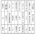
図16は、Data IDで表される識別情報の具体例を示している。
図16に示したように、Data種類としては、例えば、Gain、露光時間、ROIID、ROI位置情報、AD bit数、画素の種類情報、シャッタスピード、画素位置、およびECC有無などがある。
Data種類がGainの場合、Dataとしては、Gain設定値を含む。Data記載例としては、例えば0[dB]、6[dB]、1[倍],2[倍]などであってもよい。
Data種類が露光時間の場合、Dataとしては、露光時間情報を示す値を含む。Data記載例としては、例えば1[ms]などであってもよい。
Data種類がROI IDの場合、Dataとしては、領域ID番号を含む。Data記載例としては、例えば1,2,3・・などであってもよい。
Data種類がROI位置情報の場合、Dataとしては、左上座標等を含む。Data記載例としては、例えば左上画素のX座標などであってもよい。
Data種類がAD bit数の場合、Dataとしては、bit数を含む。Data記載例としては、例えば10[bit],12[bit]などであってもよい。
Data種類が画素の種類情報の場合、Dataとしては、RGB、IR、その他を示す値を含む。Data記載例としては、例えばR=11,G=10などであってもよい。
Data種類がシャッタスピードの場合、Dataとしては、フレームレートを含む。Data記載例としては、例えば60[fps],120[fps]などであってもよい。
Data種類が画素位置の場合、Dataとしては、上下左右を示す値、座標等を含む。Data記載例としては、例えば左上=11,X座標などであってもよい。
Data種類がECC有無の場合、Dataとしては、ECC有無を示す値を含む。Data記載例としては、例えばECCあり=1、ECCなし=0などであってもよい。
[1.3 効果]
以上説明したように、一実施の形態に係る伝送システム1の改善例によれば、画素データの識別情報を、少なくともペイロードの一部の領域に付加することが可能となるように構成したので、画素データの識別情報を確実に伝送することが可能となる。
以上説明したように、一実施の形態に係る伝送システム1の改善例によれば、画素データの識別情報を、少なくともペイロードの一部の領域に付加することが可能となるように構成したので、画素データの識別情報を確実に伝送することが可能となる。
また、一実施の形態に係る伝送システム1の改善例によれば、画素データの種類等の増加に伴い、ヘッダのData ID領域のみでは識別情報を付加するとこが困難になった場合においても、画素データの識別情報を確実に伝送することが可能となる。
なお、本明細書に記載された効果はあくまでも例示であって限定されるものではなく、また他の効果があってもよい。以降の他の実施の形態の効果についても同様である。
<2.その他の実施の形態>
本開示による技術は、上記一実施の形態の説明に限定されず種々の変形実施が可能である。
本開示による技術は、上記一実施の形態の説明に限定されず種々の変形実施が可能である。
例えば、本技術は以下のような構成を取ることもできる。
以下の構成の本技術によれば、画素データの識別情報を、少なくともペイロードの一部の領域に付加することが可能となるように構成したので、画素データの識別情報を確実に伝送することが可能となる。
以下の構成の本技術によれば、画素データの識別情報を、少なくともペイロードの一部の領域に付加することが可能となるように構成したので、画素データの識別情報を確実に伝送することが可能となる。
(1)
1フレームの画像を構成する1ライン分の画素データをペイロードに含み、前記ペイロードにヘッダを付加した複数のパケットを伝送路へと出力可能な送信部と、
前記画素データの識別情報を、少なくとも前記ペイロードの一部の領域に付加する識別情報付加部と
を備える
送信装置。
(2)
前記複数のパケットのうち、一部のパケットは、前記画素データに代えてダミー領域を前記ペイロードに含むパケットであり、
前記識別情報付加部は、前記ダミー領域に前記識別情報を示すデータを付加する
上記(1)に記載の送信装置。
(3)
前記識別情報付加部は、前記ダミー領域に複数ライン分の前記識別情報を示すデータを付加する
上記(2)に記載の送信装置。
(4)
前記識別情報付加部は、前記複数のパケットにおけるそれぞれの前記ペイロードの一部の領域に、1ラインごとの識別情報を付加する
上記(1)に記載の送信装置。
(5)
前記識別情報付加部は、前記ヘッダと、少なくとも前記ペイロードの一部の領域とに前記識別情報を付加する
上記(1)ないし(4)のいずれか1つに記載の送信装置。
(6)
前記識別情報付加部は、前記ヘッダに、前記識別情報を付加した領域に関する情報を付加する
上記(1)ないし(5)のいずれか1つに記載の送信装置。
(7)
1フレームの画像を構成する1ライン分の画素データをペイロードに含み、前記ペイロードにヘッダを付加した複数のパケットを、伝送路を介して送信装置の送信部から受信可能な受信部
を備え、
前記受信部は、少なくとも前記ペイロードの一部の領域に前記画素データの識別情報が付加されたパケットを、前記送信装置から受信可能である
受信装置。
(8)
送信装置と、
受信装置と
を含み、
前記送信装置は、
1フレームの画像を構成する1ライン分の画素データをペイロードに含み、前記ペイロードにヘッダを付加した複数のパケットを伝送路へと出力可能な送信部と、
前記画素データの識別情報を、少なくとも前記ペイロードの一部の領域に付加する識別情報付加部と
を備える
伝送システム。
(9)
前記受信装置は、
前記複数のパケットを前記伝送路を介して、前記送信装置の前記送信部から受信可能な受信部
を備え、
前記受信部は、少なくとも前記ペイロードの一部の領域に前記画素データの識別情報が付加されたパケットを、前記送信装置から受信可能である
上記(8)に記載の伝送システム。
1フレームの画像を構成する1ライン分の画素データをペイロードに含み、前記ペイロードにヘッダを付加した複数のパケットを伝送路へと出力可能な送信部と、
前記画素データの識別情報を、少なくとも前記ペイロードの一部の領域に付加する識別情報付加部と
を備える
送信装置。
(2)
前記複数のパケットのうち、一部のパケットは、前記画素データに代えてダミー領域を前記ペイロードに含むパケットであり、
前記識別情報付加部は、前記ダミー領域に前記識別情報を示すデータを付加する
上記(1)に記載の送信装置。
(3)
前記識別情報付加部は、前記ダミー領域に複数ライン分の前記識別情報を示すデータを付加する
上記(2)に記載の送信装置。
(4)
前記識別情報付加部は、前記複数のパケットにおけるそれぞれの前記ペイロードの一部の領域に、1ラインごとの識別情報を付加する
上記(1)に記載の送信装置。
(5)
前記識別情報付加部は、前記ヘッダと、少なくとも前記ペイロードの一部の領域とに前記識別情報を付加する
上記(1)ないし(4)のいずれか1つに記載の送信装置。
(6)
前記識別情報付加部は、前記ヘッダに、前記識別情報を付加した領域に関する情報を付加する
上記(1)ないし(5)のいずれか1つに記載の送信装置。
(7)
1フレームの画像を構成する1ライン分の画素データをペイロードに含み、前記ペイロードにヘッダを付加した複数のパケットを、伝送路を介して送信装置の送信部から受信可能な受信部
を備え、
前記受信部は、少なくとも前記ペイロードの一部の領域に前記画素データの識別情報が付加されたパケットを、前記送信装置から受信可能である
受信装置。
(8)
送信装置と、
受信装置と
を含み、
前記送信装置は、
1フレームの画像を構成する1ライン分の画素データをペイロードに含み、前記ペイロードにヘッダを付加した複数のパケットを伝送路へと出力可能な送信部と、
前記画素データの識別情報を、少なくとも前記ペイロードの一部の領域に付加する識別情報付加部と
を備える
伝送システム。
(9)
前記受信装置は、
前記複数のパケットを前記伝送路を介して、前記送信装置の前記送信部から受信可能な受信部
を備え、
前記受信部は、少なくとも前記ペイロードの一部の領域に前記画素データの識別情報が付加されたパケットを、前記送信装置から受信可能である
上記(8)に記載の伝送システム。
本出願は、日本国特許庁において2019年11月20日に出願された日本特許出願番号第2019-209579号を基礎として優先権を主張するものであり、この出願のすべての内容を参照によって本出願に援用する。
当業者であれば、設計上の要件や他の要因に応じて、種々の修正、コンビネーション、サブコンビネーション、および変更を想到し得るが、それらは添付の請求の範囲やその均等物の範囲に含まれるものであることが理解される。
Claims (9)
- 1フレームの画像を構成する1ライン分の画素データをペイロードに含み、前記ペイロードにヘッダを付加した複数のパケットを伝送路へと出力可能な送信部と、
前記画素データの識別情報を、少なくとも前記ペイロードの一部の領域に付加する識別情報付加部と
を備える
送信装置。 - 前記複数のパケットのうち、一部のパケットは、前記画素データに代えてダミー領域を前記ペイロードに含むパケットであり、
前記識別情報付加部は、前記ダミー領域に前記識別情報を示すデータを付加する
請求項1に記載の送信装置。 - 前記識別情報付加部は、前記ダミー領域に複数ライン分の前記識別情報を示すデータを付加する
請求項2に記載の送信装置。 - 前記識別情報付加部は、前記複数のパケットにおけるそれぞれの前記ペイロードの一部の領域に、1ラインごとの識別情報を付加する
請求項1に記載の送信装置。 - 前記識別情報付加部は、前記ヘッダと、少なくとも前記ペイロードの一部の領域とに前記識別情報を付加する
請求項1に記載の送信装置。 - 前記識別情報付加部は、前記ヘッダに、前記識別情報を付加した領域に関する情報を付加する
請求項1に記載の送信装置。 - 1フレームの画像を構成する1ライン分の画素データをペイロードに含み、前記ペイロードにヘッダを付加した複数のパケットを、伝送路を介して送信装置の送信部から受信可能な受信部
を備え、
前記受信部は、少なくとも前記ペイロードの一部の領域に前記画素データの識別情報が付加されたパケットを、前記送信装置から受信可能である
受信装置。 - 送信装置と、
受信装置と
を含み、
前記送信装置は、
1フレームの画像を構成する1ライン分の画素データをペイロードに含み、前記ペイロードにヘッダを付加した複数のパケットを伝送路へと出力可能な送信部と、
前記画素データの識別情報を、少なくとも前記ペイロードの一部の領域に付加する識別情報付加部と
を備える
伝送システム。 - 前記受信装置は、
前記複数のパケットを前記伝送路を介して、前記送信装置の前記送信部から受信可能な受信部
を備え、
前記受信部は、少なくとも前記ペイロードの一部の領域に前記画素データの識別情報が付加されたパケットを、前記送信装置から受信可能である
請求項8に記載の伝送システム。
Priority Applications (3)
| Application Number | Priority Date | Filing Date | Title |
|---|---|---|---|
| JP2021558351A JP7550785B2 (ja) | 2019-11-20 | 2020-11-13 | 送信装置、および伝送システム |
| EP20891331.9A EP4064682A4 (en) | 2019-11-20 | 2020-11-13 | TRANSMITTER, RECEIVER AND TRANSMISSION SYSTEM |
| US17/776,761 US20220385959A1 (en) | 2019-11-20 | 2020-11-13 | Transmission device, reception device, and transmission system |
Applications Claiming Priority (2)
| Application Number | Priority Date | Filing Date | Title |
|---|---|---|---|
| JP2019209579 | 2019-11-20 | ||
| JP2019-209579 | 2019-11-20 |
Publications (1)
| Publication Number | Publication Date |
|---|---|
| WO2021100627A1 true WO2021100627A1 (ja) | 2021-05-27 |
Family
ID=75981297
Family Applications (1)
| Application Number | Title | Priority Date | Filing Date |
|---|---|---|---|
| PCT/JP2020/042423 Ceased WO2021100627A1 (ja) | 2019-11-20 | 2020-11-13 | 送信装置、受信装置、および伝送システム |
Country Status (4)
| Country | Link |
|---|---|
| US (1) | US20220385959A1 (ja) |
| EP (1) | EP4064682A4 (ja) |
| JP (1) | JP7550785B2 (ja) |
| WO (1) | WO2021100627A1 (ja) |
Families Citing this family (1)
| Publication number | Priority date | Publication date | Assignee | Title |
|---|---|---|---|---|
| US20230283816A1 (en) * | 2020-06-26 | 2023-09-07 | Nippon Telegraph And Telephone Corporation | Video distribution system, video distribution method, transmission device, and transmission program |
Citations (4)
| Publication number | Priority date | Publication date | Assignee | Title |
|---|---|---|---|---|
| JP2012120158A (ja) | 2010-11-12 | 2012-06-21 | Sony Corp | 画像出力装置、画像出力方法、画像処理装置、画像処理方法、プログラム、データ構造、および撮像装置 |
| WO2018225534A1 (ja) * | 2017-06-09 | 2018-12-13 | ソニーセミコンダクタソリューションズ株式会社 | 受信装置、送信装置、制御方法、プログラム、および送受信システム |
| WO2018225449A1 (ja) * | 2017-06-09 | 2018-12-13 | ソニーセミコンダクタソリューションズ株式会社 | 映像送信装置および映像受信装置 |
| JP2019209579A (ja) | 2018-06-04 | 2019-12-12 | キヤノン株式会社 | 画像形成装置、情報処理方法及びプログラム |
Family Cites Families (3)
| Publication number | Priority date | Publication date | Assignee | Title |
|---|---|---|---|---|
| JP5162939B2 (ja) * | 2007-03-30 | 2013-03-13 | ソニー株式会社 | 情報処理装置および方法、並びにプログラム |
| TWI686085B (zh) * | 2012-11-29 | 2020-02-21 | 日商索尼半導體解決方案公司 | 攝像裝置及圖像感測器之資料傳送方法、資訊處理裝置及資訊處理方法以及程式 |
| JP2020056953A (ja) * | 2018-10-03 | 2020-04-09 | キヤノン株式会社 | 防振装置、画像処理装置、及び検出方法 |
-
2020
- 2020-11-13 EP EP20891331.9A patent/EP4064682A4/en active Pending
- 2020-11-13 WO PCT/JP2020/042423 patent/WO2021100627A1/ja not_active Ceased
- 2020-11-13 JP JP2021558351A patent/JP7550785B2/ja active Active
- 2020-11-13 US US17/776,761 patent/US20220385959A1/en not_active Abandoned
Patent Citations (4)
| Publication number | Priority date | Publication date | Assignee | Title |
|---|---|---|---|---|
| JP2012120158A (ja) | 2010-11-12 | 2012-06-21 | Sony Corp | 画像出力装置、画像出力方法、画像処理装置、画像処理方法、プログラム、データ構造、および撮像装置 |
| WO2018225534A1 (ja) * | 2017-06-09 | 2018-12-13 | ソニーセミコンダクタソリューションズ株式会社 | 受信装置、送信装置、制御方法、プログラム、および送受信システム |
| WO2018225449A1 (ja) * | 2017-06-09 | 2018-12-13 | ソニーセミコンダクタソリューションズ株式会社 | 映像送信装置および映像受信装置 |
| JP2019209579A (ja) | 2018-06-04 | 2019-12-12 | キヤノン株式会社 | 画像形成装置、情報処理方法及びプログラム |
Non-Patent Citations (1)
| Title |
|---|
| See also references of EP4064682A4 |
Also Published As
| Publication number | Publication date |
|---|---|
| EP4064682A4 (en) | 2023-01-18 |
| EP4064682A1 (en) | 2022-09-28 |
| US20220385959A1 (en) | 2022-12-01 |
| JP7550785B2 (ja) | 2024-09-13 |
| JPWO2021100627A1 (ja) | 2021-05-27 |
Similar Documents
| Publication | Publication Date | Title |
|---|---|---|
| JP6349259B2 (ja) | イメージセンサおよびそのデータ伝送方法、情報処理装置および情報処理方法、電子機器、並びにプログラム | |
| CN202889529U (zh) | 图像输出装置、图像处理装置和成像装置 | |
| US8538276B2 (en) | Method and apparatus for visible light communication with image processing | |
| JP7547217B2 (ja) | 送信装置、送信方法、受信装置、受信方法、および送受信装置 | |
| JP2013078377A5 (ja) | ||
| JP7152475B2 (ja) | 送信装置、受信装置、及び通信システム | |
| CN110692222A (zh) | 接收装置、发送装置、控制方法、程序及发送和接收系统 | |
| JP7692361B2 (ja) | 送信装置、受信装置、および伝送システム | |
| JP7550785B2 (ja) | 送信装置、および伝送システム | |
| US20220239831A1 (en) | Transmission device, transmission method, reception device, reception method, and transmission-reception device | |
| JP7611823B2 (ja) | 送信装置および通信システム | |
| JP2009141453A (ja) | データ伝送装置、データ送信装置、データ受信装置及びデータ伝送システム | |
| JP7504803B2 (ja) | 画像処理装置及び画像処理方法 | |
| KR20250005328A (ko) | 송신 장치, 송신 방법, 수신 장치, 수신 방법, 프로그램 및 송신 시스템 |
Legal Events
| Date | Code | Title | Description |
|---|---|---|---|
| 121 | Ep: the epo has been informed by wipo that ep was designated in this application |
Ref document number: 20891331 Country of ref document: EP Kind code of ref document: A1 |
|
| ENP | Entry into the national phase |
Ref document number: 2021558351 Country of ref document: JP Kind code of ref document: A |
|
| NENP | Non-entry into the national phase |
Ref country code: DE |
|
| ENP | Entry into the national phase |
Ref document number: 2020891331 Country of ref document: EP Effective date: 20220620 |