WO2021100799A1 - 電源システム及びその制御方法 - Google Patents
電源システム及びその制御方法 Download PDFInfo
- Publication number
- WO2021100799A1 WO2021100799A1 PCT/JP2020/043159 JP2020043159W WO2021100799A1 WO 2021100799 A1 WO2021100799 A1 WO 2021100799A1 JP 2020043159 W JP2020043159 W JP 2020043159W WO 2021100799 A1 WO2021100799 A1 WO 2021100799A1
- Authority
- WO
- WIPO (PCT)
- Prior art keywords
- current
- voltage
- storage unit
- battery
- power storage
- Prior art date
- Legal status (The legal status is an assumption and is not a legal conclusion. Google has not performed a legal analysis and makes no representation as to the accuracy of the status listed.)
- Ceased
Links
Images






Classifications
-
- H—ELECTRICITY
- H02—GENERATION; CONVERSION OR DISTRIBUTION OF ELECTRIC POWER
- H02J—ELECTRIC POWER NETWORKS; CIRCUIT ARRANGEMENTS OR SYSTEMS FOR SUPPLYING OR DISTRIBUTING ELECTRIC POWER; SYSTEMS FOR STORING ELECTRIC ENERGY
- H02J7/00—Circuit arrangements for charging or discharging batteries or for supplying loads from batteries
- H02J7/50—Circuit arrangements for charging or discharging batteries or for supplying loads from batteries acting upon multiple batteries simultaneously or sequentially
- H02J7/52—Circuit arrangements for charging or discharging batteries or for supplying loads from batteries acting upon multiple batteries simultaneously or sequentially for charge balancing, e.g. equalisation of charge between batteries
- H02J7/56—Active balancing, e.g. using capacitor-based, inductor-based or DC-DC converters
-
- H—ELECTRICITY
- H02—GENERATION; CONVERSION OR DISTRIBUTION OF ELECTRIC POWER
- H02J—ELECTRIC POWER NETWORKS; CIRCUIT ARRANGEMENTS OR SYSTEMS FOR SUPPLYING OR DISTRIBUTING ELECTRIC POWER; SYSTEMS FOR STORING ELECTRIC ENERGY
- H02J7/00—Circuit arrangements for charging or discharging batteries or for supplying loads from batteries
- H02J7/34—Parallel operation in networks using both storage and other DC sources, e.g. providing buffering
- H02J7/342—The other DC source being a battery actively interacting with the first one, i.e. battery to battery charging
-
- G—PHYSICS
- G01—MEASURING; TESTING
- G01R—MEASURING ELECTRIC VARIABLES; MEASURING MAGNETIC VARIABLES
- G01R19/00—Arrangements for measuring currents or voltages or for indicating presence or sign thereof
- G01R19/10—Measuring sum, difference or ratio
-
- H—ELECTRICITY
- H02—GENERATION; CONVERSION OR DISTRIBUTION OF ELECTRIC POWER
- H02J—ELECTRIC POWER NETWORKS; CIRCUIT ARRANGEMENTS OR SYSTEMS FOR SUPPLYING OR DISTRIBUTING ELECTRIC POWER; SYSTEMS FOR STORING ELECTRIC ENERGY
- H02J7/00—Circuit arrangements for charging or discharging batteries or for supplying loads from batteries
- H02J7/50—Circuit arrangements for charging or discharging batteries or for supplying loads from batteries acting upon multiple batteries simultaneously or sequentially
-
- H—ELECTRICITY
- H02—GENERATION; CONVERSION OR DISTRIBUTION OF ELECTRIC POWER
- H02J—ELECTRIC POWER NETWORKS; CIRCUIT ARRANGEMENTS OR SYSTEMS FOR SUPPLYING OR DISTRIBUTING ELECTRIC POWER; SYSTEMS FOR STORING ELECTRIC ENERGY
- H02J7/00—Circuit arrangements for charging or discharging batteries or for supplying loads from batteries
- H02J7/90—Regulation of charging or discharging current or voltage
- H02J7/94—Regulation of charging or discharging current or voltage in response to battery current
-
- H—ELECTRICITY
- H02—GENERATION; CONVERSION OR DISTRIBUTION OF ELECTRIC POWER
- H02J—ELECTRIC POWER NETWORKS; CIRCUIT ARRANGEMENTS OR SYSTEMS FOR SUPPLYING OR DISTRIBUTING ELECTRIC POWER; SYSTEMS FOR STORING ELECTRIC ENERGY
- H02J7/00—Circuit arrangements for charging or discharging batteries or for supplying loads from batteries
- H02J7/90—Regulation of charging or discharging current or voltage
- H02J7/96—Regulation of charging or discharging current or voltage in response to battery voltage
-
- H—ELECTRICITY
- H02—GENERATION; CONVERSION OR DISTRIBUTION OF ELECTRIC POWER
- H02J—ELECTRIC POWER NETWORKS; CIRCUIT ARRANGEMENTS OR SYSTEMS FOR SUPPLYING OR DISTRIBUTING ELECTRIC POWER; SYSTEMS FOR STORING ELECTRIC ENERGY
- H02J1/00—Circuit arrangements for DC mains or DC distribution networks
- H02J1/10—Parallel operation of DC sources
- H02J1/102—Parallel operation of DC sources being switching converters
-
- H—ELECTRICITY
- H02—GENERATION; CONVERSION OR DISTRIBUTION OF ELECTRIC POWER
- H02J—ELECTRIC POWER NETWORKS; CIRCUIT ARRANGEMENTS OR SYSTEMS FOR SUPPLYING OR DISTRIBUTING ELECTRIC POWER; SYSTEMS FOR STORING ELECTRIC ENERGY
- H02J2207/00—Details of circuit arrangements for charging or discharging batteries or supplying loads from batteries
- H02J2207/20—Charging or discharging characterised by the power electronics converter
-
- H—ELECTRICITY
- H02—GENERATION; CONVERSION OR DISTRIBUTION OF ELECTRIC POWER
- H02J—ELECTRIC POWER NETWORKS; CIRCUIT ARRANGEMENTS OR SYSTEMS FOR SUPPLYING OR DISTRIBUTING ELECTRIC POWER; SYSTEMS FOR STORING ELECTRIC ENERGY
- H02J7/00—Circuit arrangements for charging or discharging batteries or for supplying loads from batteries
- H02J7/14—Circuit arrangements for charging or discharging batteries or for supplying loads from batteries for charging batteries from dynamo-electric generators driven at varying speed, e.g. on vehicle
- H02J7/1423—Circuit arrangements for charging or discharging batteries or for supplying loads from batteries for charging batteries from dynamo-electric generators driven at varying speed, e.g. on vehicle with multiple batteries
-
- H—ELECTRICITY
- H02—GENERATION; CONVERSION OR DISTRIBUTION OF ELECTRIC POWER
- H02J—ELECTRIC POWER NETWORKS; CIRCUIT ARRANGEMENTS OR SYSTEMS FOR SUPPLYING OR DISTRIBUTING ELECTRIC POWER; SYSTEMS FOR STORING ELECTRIC ENERGY
- H02J7/00—Circuit arrangements for charging or discharging batteries or for supplying loads from batteries
- H02J7/80—Circuit arrangements for charging or discharging batteries or for supplying loads from batteries including monitoring or indicating arrangements
- H02J7/82—Control of state of charge [SOC]
-
- H—ELECTRICITY
- H02—GENERATION; CONVERSION OR DISTRIBUTION OF ELECTRIC POWER
- H02J—ELECTRIC POWER NETWORKS; CIRCUIT ARRANGEMENTS OR SYSTEMS FOR SUPPLYING OR DISTRIBUTING ELECTRIC POWER; SYSTEMS FOR STORING ELECTRIC ENERGY
- H02J7/00—Circuit arrangements for charging or discharging batteries or for supplying loads from batteries
- H02J7/855—Circuit arrangements for charging or discharging batteries or for supplying loads from batteries with circuits adapted for supplying loads from the battery
Definitions
- the present invention relates to a power supply system in which a plurality of charge / discharge charge storage units are connected in parallel to each other via a voltage converter, and a control method thereof.
- Japanese Patent Application Laid-Open No. 2016-25791 discloses a power supply system in which a plurality of rechargeable and dischargeable batteries (storage units) are connected in parallel to each other via a voltage converter.
- the present invention has been made in consideration of such a problem, and is a power supply system capable of equalizing the voltage or SOC of a plurality of power storage units connected in parallel with each other while avoiding deterioration of the power storage units.
- An object of the present invention is to provide a control method thereof.
- a plurality of charge / dischargeable power storage units an input side is connected to the plurality of power storage units, an output side is connected in parallel to each other, and voltages of the plurality of power storage units connected to the input side are applied.
- a plurality of voltage converters that are converted at an arbitrary transformation rate and output the converted voltage to the output side, and are connected to the input sides of the plurality of voltage converters and flow from the plurality of storage units to the input side.
- the present invention relates to a power supply system including a plurality of current measuring instruments for measuring current, and a control method thereof.
- the determination unit and the current difference determination unit that determines the current difference between the current flowing from the residual storage unit and the current flowing from the reference storage unit based on the currents measured by the plurality of current measuring instruments. Further, it is provided with a transformation rate determining unit that determines the transformation rate of the voltage converter connected to the residual storage unit based on the current difference.
- the power storage unit determination unit is used to determine at least one of the power storage units as the reference power storage unit on the charging side, and discharge the remaining power storage unit.
- the current flowing from the residual storage unit and the current flowing from the reference storage unit based on the currents measured by the plurality of current measuring instruments using the step of determining the residual power storage unit on the side and the current difference determination unit. It has a step of determining the current difference from the current and a step of determining the transformation rate of the voltage converter connected to the residual storage unit based on the determined current difference using the transformation rate determining unit. ..
- the current difference between the current flowing from the residual storage unit and the current flowing from the reference storage unit is fed back, and the transformation rate of the voltage converter connected to the residual storage unit is set so that the current difference becomes small. decide.
- the voltage or SOC of the plurality of power storage units connected in parallel can be equalized while avoiding deterioration of the power storage units. it can.
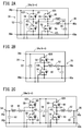
- FIG. 2A is a circuit diagram of a step-down or buck-boost type voltage converter
- FIG. 2B is a circuit diagram of a step-down voltage converter
- FIG. 2C is a circuit diagram of a buck-boost type voltage converter. .. It is a timing chart which shows the buck-boost operation.
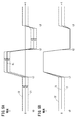
- FIG. 5A is a timing chart of each current when the control method of the present embodiment is not used
- FIG. 5B is a timing chart of each current when the control method of the present embodiment is used. It is a figure which shows the list of the charge / discharge state classification of each battery.
- FIG. 9A is an explanatory diagram of a process of adjusting each battery voltage to a reference voltage
- FIG. 9B is an explanatory diagram of an actual control process.
- It is a timing chart which illustrated the discharge process.
- It is a block diagram which schematically illustrated the equalization unit.
- It is a block diagram which illustrated the control method which concerns on this embodiment.
- It is a timing chart which illustrated the relationship between the target current and the 2nd current.
- It is a timing chart which shows the time change of each battery voltage, each current, and each step-down rate.
- 16A to 16D are explanatory views showing problems when control using the current difference is not performed. It is a timing chart which shows the vehicle speed of an electric vehicle, each current, and time change of each SOC.
- the power supply system 10 includes a plurality of batteries 12a to 12d (storage units), an equalization unit 14, a control device 16, and a motor generator ECU (MG-ECU) 18. , Power drive unit (PDU) 20 and the like.
- FIG. 1 illustrates a case where four batteries 12a to 12d (hereinafter, also referred to as first to fourth batteries 12a to 12d) are arranged.
- the power supply system 10 is applied to the power supply system of an electric vehicle 22 such as a two-wheeled vehicle or a four-wheeled vehicle, for example.
- the plurality of batteries 12a to 12d are power storage units that can be attached to and detached from the power supply system 10 and can be charged and discharged.
- the plurality of batteries 12a to 12d are each housed in a battery pack (not shown) including a battery management system (BMU) that monitors the batteries 12a to 12d, and by attaching and detaching the battery pack to and from the power supply system 10, the power supply system It is removable with respect to 10.
- BMU battery management system
- at least one of the plurality of batteries 12a to 12d may be detachable from the power supply system 10.
- each battery pack, equalization unit 14, control device 16, MG-ECU 18, and PDU 20 can transmit and receive signals or information via a communication line (not shown) constituting the Controller Area Network (CAN). ..
- the equalization unit 14 includes a plurality of voltage converters 24a to 24d, a plurality of current measuring instruments 26a to 26d, a plurality of input side voltage measuring instruments (voltage measuring instruments) 28a to 28d, and an output side voltage measuring instrument 30. , With a plurality of temperature sensors 32.
- the plurality of voltage converters 24a to 24d are, for example, DC / DC converters having an input side 34 on the primary side and an output side 36 on the secondary side, respectively, and the battery 12a connected to the input side 34.
- Converted voltage (output voltage V0) by converting a voltage of ⁇ 12d (battery voltages V1 to V4) with an arbitrary transformation rate Tr (step-up rate Tru or step-down rate Trd (hereinafter, also referred to as step-down rate R)). Is output to the output side 36.
- Tr step-up rate Tru or step-down rate Trd
- R step-down rate
- four voltage converters 24a to 24d correspond to the first to fourth batteries 12a to 12d in the equalization unit 14.
- the first to fourth voltage converters 24a to 24d step down the battery voltages V1 to V4 of the first to fourth batteries 12a to 12d at arbitrary step-down rates R1 to R4, and the stepped-down battery voltages V1 to V1 to A case where V4 is output to the output side 36 as an output voltage V0 will be described.
- the input side 34 of the first to fourth voltage converters 24a to 24d is connected to one of the first to fourth batteries 12a to 12d, the batteries 12a to 12d. That is, the positive electrode terminals of the first to fourth batteries 12a to 12d and the positive electrode terminals 38p of the input side 34 of the first to fourth voltage converters 24a to 24d are connected, and the negative electrodes of the first to fourth batteries 12a to 12d are connected. The terminal and the negative electrode terminal 38m on the input side 34 of the first to fourth voltage converters 24a to 24d are connected. Further, the output sides 36 of the first to fourth voltage converters 24a to 24d are connected in parallel to the PDU 20 by being connected in parallel to each other.
- the positive electrode terminal 40p on the output side 36 of the first to fourth voltage converters 24a to 24d is connected to the positive electrode terminal of the PDU 20, and the negative electrode terminal 40m on the output side 36 of the first to fourth voltage converters 24a to 24d. Is connected to the negative electrode terminal of the PDU 20.
- the plurality of input side voltage measuring instruments 28a to 28d are the input side 34 of the first to fourth voltage converters 24a to 24d, and the first to fourth voltage measuring instruments 28a to 24d. It is a voltage sensor connected between the positive electrode terminal and the negative electrode terminal of the fourth battery 12a to 12d.
- the plurality of current measuring instruments 26a to 26d (hereinafter, also referred to as the first to fourth current measuring instruments 26a to 26d) are the input sides 34 of the first to fourth voltage converters 24a to 24d, and the first to fourth current measuring instruments 26a to 26d.
- This is a current sensor connected between the positive electrode terminals of the fourth batteries 12a to 12d and the positive electrode terminals 38p of the first to fourth voltage converters 24a to 24d.
- the output side voltage measuring instrument 30 is a voltage sensor connected between the positive electrode terminal and the negative electrode terminal of the PDU 20 on the output side 36 of the first to fourth voltage converters 24a to 24d.
- the plurality of temperature sensors 32 detect the temperatures of the switching elements 42H and 42L (see FIGS. 2A to 2C) constituting the first to fourth voltage converters 24a to 24d, respectively. Note that FIG. 1 illustrates a case where two temperature sensors 32 are provided.
- the PDU 20 includes a three-phase bridge type inverter.
- the first to fourth voltage converters 24a to 24d are connected in parallel to the input side of the PDU 20.
- a three-phase AC motor 44 which is a load of the power supply system 10, is electrically connected to the output side of the PDU 20.
- the PDU 20 converts DC power into three-phase AC power and supplies it to the motor 44.
- the motor 44 can be driven and the electric vehicle 22 can be driven.
- the PDU 20 converts the AC power generated by the motor 44 into DC power.
- the first to fourth batteries 12a to 12d can be charged with DC power via the first to fourth voltage converters 24a to 24d.
- the MG-ECU 18 (storage unit determination unit) is an ECU (electronic control device) for controlling the PDU 20 and the motor 44, and can send and receive signals or information between the control device 16 and the PDU 20. That is, the MG-ECU 18 supplies a control signal (a signal indicating a torque command value) for operating the switching elements 42H and 42L constituting the PDU 20. On the other hand, the PDU 20 transmits the status of the PDU 20 and the like. The motor 44 transmits the state of the motor 44 and the like. The MG-ECU 18 calculates the required output of the motor 44 based on the information transmitted from the PDU 20 and the motor 44, and transmits the calculated requested output to the control device 16.
- a control signal a signal indicating a torque command value
- the control device 16 is an ECU for controlling the equalization unit 14, and has a control unit 46 (storage unit determination unit, current difference determination unit, transformation rate determination unit), a command unit 48, and a table 50.
- the control unit 46 has the battery voltages V1 to V4 of the first to fourth batteries 12a to 12d measured by the first to fourth voltage measuring instruments 28a to 28d, and the first to fourth current measuring instruments 26a to 26d measured by the first to fourth current measuring instruments 26a to 26d.
- the 1st to 4th currents I1 to I4 the output voltage V0 (load voltage) measured by the output side voltage measuring instrument 30, and the temperatures of the 1st to 4th voltage converters 24a to 24d measured by the plurality of temperature sensors 32. get.
- control unit 46 calculates (determines) the transformation rate Tr and the like based on the request output from the MG-ECU 18 and the target value (target current Itar) of the current flowing through the input side 34 stored in the table 50. Do.
- the command unit 48 outputs a command signal (gate signal supplied to the switching elements 42H and 42L of the first to fourth voltage converters 24a to 24d) based on the transformation rate Tr determined by the control unit 46 to the equalization unit 14. To do. The details of the processing of the control device 16 and the MG-ECU 18 will be described later.
- FIGS. 2A to 2C are circuit diagrams showing specific examples of the first to fourth voltage converters 24a to 24d of FIG.
- the first to fourth voltage converters 24a to 24d are, for example, a step-down type or buck-boost type (see FIG. 2A), a step-down type (see FIG. 2B), or a buck-boost type (see FIG. 2C) DC / DC converter. .. Since the configurations and operations of these DC / DC converters are well known, the connection relationship of each component in the circuit diagrams of FIGS. 2A to 2C will be briefly described here.
- a capacitor 52 is connected between the positive electrode terminal 38p and the negative electrode terminal 38m on the input side 34.
- Two sets of circuits which are a set of two switching elements 42H and 42L connected in series and a coil 54, are connected in parallel to the capacitor 52.
- one switching element 42H is a high-side switching element connected to the positive electrode terminal 38p side of the capacitor 52.
- the other switching element 42L is a low-side switching element connected to the negative electrode terminal 38m side of the capacitor 52 and the negative electrode terminal 40m on the output side 36.
- One end of the coil 54 is connected to the midpoint of the two switching elements 42H and 42L. The other end of the coil 54 is connected to the positive electrode terminal 40p on the output side 36.
- a capacitor 56 is connected between the positive electrode terminal 40p and the negative electrode terminal 40m on the output side 36.
- the switching elements 42H and 42L are configured by connecting a MOSFET (Metal Oxide Semiconductor Field Effect Transistor) 58 and a Zener diode 60 which is a parasitic diode in parallel.
- MOSFET Metal Oxide Semiconductor Field Effect Transistor
- a capacitor 52 is connected between the positive electrode terminal 38p and the negative electrode terminal 38m on the input side 34.
- Two switching elements 42H and 42L connected in series are connected in parallel to the capacitor 52.
- One switching element 42H is a high-side switching element connected to the positive electrode terminal 38p side of the capacitor 52.
- the other switching element 42L is a low-side switching element connected to the negative electrode terminal 38m side of the capacitor 52 and the negative electrode terminal 40m on the output side 36.
- a series circuit of the coil 54 and the resistor 62 is connected between the midpoint of the two switching elements 42H and 42L and the positive electrode terminal 40p on the output side 36.
- a capacitor 56 is connected between the positive electrode terminal 40p and the negative electrode terminal 40m on the output side 36.
- a capacitor 52 is connected between the positive electrode terminal 38p and the negative electrode terminal 38m on the input side 34.
- the positive electrode terminal 38p side of the capacitor 52 is connected to the midpoint of the two switching elements 42H and 42L connected in series via a series circuit of the coil 64 and the resistor 66.
- Capacitors 68 are connected in parallel to the two switching elements 42H and 42L. Further, a circuit having the same configuration as that shown in FIG. 2B is connected in parallel to the output side 36 of the capacitor 68.
- the transformation rate Tr in FIG. 2A, step-up rate Tru or step-down rate R, FIG. 2B
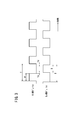
- FIG. 3 shows, as an example, a timing chart of gate signals supplied to the gate terminals of the switching elements 42H and 42L in the step-down circuit of FIG. 2B.
- the period of the gate signal is T
- the high level time of the gate signal (“Hi side duty” in FIG. 3) supplied to the high side switching element 42H is U
- the gate supplied to the low side switching element 42L is expressed by the following equation (1).
- T U + D + Td ⁇ 2
- step-down rate R is expressed by the following equation (2), where Vin is the voltage on the input side 34 (battery voltages V1 to V4) and Vout is the voltage on the output side 36 (output voltage V0).
- Vin is the voltage on the input side 34 (battery voltages V1 to V4) and Vout is the voltage on the output side 36 (output voltage V0).
- Vout is the voltage on the output side 36 (output voltage V0).
- the step-down rate R is specified by the control unit 46, and the command unit 48 supplies the gate signal corresponding to the step-down rate R to the equalization unit 14 to drive the first to fourth voltage converters 24a to 24d.
- the desired output voltage V0 can be obtained.
- the characteristic function of the present embodiment is that the first to fourth batteries 12a to 12d having different voltages or SOCs are connected in parallel to each other, and the first to fourth batteries 12a to 12d have the same voltage or SOC.
- the first to fourth currents I1 to I4 are passed between them for charging and discharging, the first to fourth currents I1 to I4 flowing from the first to fourth batteries 12a to 12d to the input side 34 are sent to the control device 16.
- control unit 46 of the control device 16 determines the current difference between the current flowing from the charging side battery (reference storage unit) and the current flowing from the discharging side battery (residual storage unit), and then determines the determined current.
- the control unit 46 of the control device 16 determines the current difference between the current flowing from the charging side battery (reference storage unit) and the current flowing from the discharging side battery (residual storage unit), and then determines the determined current.
- step-down rate R such that the difference becomes small and controlling the first to fourth voltage converters 24a to 24d with the determined step-down rate R, deterioration of each battery 12a to 12d is avoided, and each battery is used.
- the purpose is to equalize the voltage or SOC of 12a to 12d.
- FIG. 4 is a schematic circuit diagram of the power supply system 10 of FIG.
- the equalization unit 14 and the like are not shown, and the resistors showing the internal resistances (resistance value r) of the first to fourth batteries 12a to 12d and the first to fourth batteries 12a to 12d are omitted.
- a series circuit with the devices 70a to 70d (hereinafter, also referred to as the first to fourth resistors 70a to 70d) is connected in parallel, and the load 72 (motor 44) is on the positive side of the first to fourth batteries 12a to 12d. Is illustrated.
- the current flowing through the load 72 is defined as It (hereinafter, also referred to as load current).
- the voltage difference between the positive side of the series circuit of the first battery 12a and the first resistor 70a and the positive side of the series circuit of the second battery 12b and the second resistor 70b is Vd1, the first battery 12a and the first resistor.
- the voltage difference between the positive side of the series circuit of the device 70a and the positive side of the series circuit of the third battery 12c and the third resistor 70c is Vd2, and the positive side of the series circuit of the first battery 12a and the first resistor 70a and the first. 4
- Vd3 be the voltage difference between the battery 12d and the fourth resistor 70d on the positive side of the series circuit.
- the series circuit of the first battery 12a and the first resistor 70a and the series circuit of the second battery 12b and the second resistor 70b are connected in parallel.
- the first current I1 and the second current I2 are represented by the following equations (5) and (6) based on Kirchhoff's law.
- I1 It / 2 + Vd1 / (4 ⁇ r)
- I2 It / 2-Vd1 / (4 ⁇ r) (6)
- the first to third currents I1 to I3 are represented by the following equations (7) to (9) based on Kirchhoff's law.
- I1 It / 3 + (Vd1 + Vd2) / (6 ⁇ r) (7)
- I2 It / 3 + (-2 ⁇ Vd1 + Vd2) / (6 ⁇ r) (8)
- I3 It / 3 + (Vd1-2 ⁇ Vd2) / (6 ⁇ r) (9)
- I1 It / 4 + (Vd1 + Vd2 + Vd3) / (8 ⁇ r) (10)
- I2 It / 4 + (-3 ⁇ Vd1 + Vd2 + Vd3) / (8 ⁇ r) (11)
- I3 It / 4 + (Vd1-3 ⁇ Vd2 + Vd3) / (8 ⁇ r) (12)
- I4 It / 4 + (Vd1 + Vd2-3 ⁇ Vd3) / (8 ⁇ r) (13)
- the first to fourth currents I1 to I4 include voltage differences Vd1 to Vd3. Therefore, theoretically, if the first to fourth currents I1 to I4 are measured by the first to fourth current measuring instruments 26a to 26d and the measured first to fourth currents I1 to I4 are fed back to the control device 16, It is possible to adjust the desired voltage difference Vd1 to Vd3 based on the first to fourth currents I1 to I4.
- FIG. 5A and 5B are timing charts showing an example of time changes of the first current I1, the second current I2, and the load current It.
- FIG. 5A shows a case where the feedback of the first current I1 and the second current I2 is not performed.
- FIG. 5B shows a case where feedback of the first current I1 and the second current I2 is performed.
- the voltage difference Vd1 causes a current difference of 2 ⁇ A between the first current I1 and the second current I2.
- the first current I1 becomes a negative current, that is, a charging current
- the second current I2 becomes a positive current, that is, a discharging current. That is, since the load 72 does not exist, the second current I2 flowing from the second battery 12b flows into the first battery 12a as the first current I1 and charges the first battery 12a.
- the load 72 in the time zone from the time point t1 to the time point t2, the load 72 is in a power running state, and due to the voltage difference Vd1, the first current I1 and the second current I2 have a current of 2 ⁇ B. There is a difference. In this time zone, both the first current I1 and the second current I2 become discharge currents. That is, the first current I1 and the second current I2 flowing from the first battery 12a and the second battery 12b flow to the load 72 as the load current It.
- the load 72 in the time zone from the time point t2 to the time point t3, the load 72 is in the regenerative state, and the load 72 charges the first battery 12a and the second battery 12b.
- the voltage difference Vd1 causes a current difference of 2 ⁇ C between the first current I1 and the second current I2.
- both the first current I1 and the second current I2 become charging currents. That is, the load current It splits into the first current I1 and the second current I2, and flows into the first battery 12a and the second battery 12b.
- the first current I1 and the second current I2 are fed back to the control device 16, and the voltage difference is reduced so that the current difference between the fed-back first current I1 and the second current I2 becomes small.
- the current difference gradually decreases and changes to 0, that is, the first current I1 and the second current I2 have the same current values as the load current It. To do.
- a constant current difference occurs between the time zone from t0 to t1 in which the load 72 does not exist and the time zone after t3.
- FIG. 6 is an explanatory diagram illustrating a charging / discharging method for the first to fourth batteries 12a to 12d (see FIGS. 1 and 4) in the present embodiment.
- the charging / discharging method in No. 2 (first and second batteries 12a, 12b) will be described.
- MPP1 to MPP4 indicate the first to fourth batteries 12a to 12d.
- symbols such as “3H1L” are the number of batteries (residual storage unit) on the discharging side (the number indicated before “H") and the number of batteries (reference storage unit) on the charging side. (The number written before the “L”).
- the target values (target current Itar) of the first to fourth currents I1 to I4 are shown below the graphic symbols (denoted by batteries) indicating the first to fourth batteries 12a to 12d. ..
- the target current Itar of the battery on the discharge side is indicated by a symbol such as “Id”.
- the target current Itar indicates the target value of the current flowing from the battery on the discharging side, and the target current of the battery on the charging side is set to 0 [A]. Therefore, the actual current value (actual current) flowing from the first to fourth batteries 12a to 12d may differ from the target current.
- the target currents of the first to fourth currents I1 to I4 are 3.0 ⁇ Id [A], 0.0 [A], 0.0 [A]. , 0.0 [A].
- the actual currents of the first to fourth currents I1 to I4 are +2.25 ⁇ Id [A], ⁇ 0.75 ⁇ Id [A], ⁇ 0.75 ⁇ Id [A], ⁇ 0. It becomes .75 ⁇ Id [A].
- the positive and negative codes attached to the first to fourth currents I1 to I4 are positive (+) in the direction of flow from the first to fourth batteries 12a to 12d to the first to fourth voltage converters 24a to 24d.
- the direction in which the first to fourth voltage converters 24a to 24d flow into the first to fourth batteries 12a to 12d is negative ( ⁇ ).
- the target current Itar is preset in Table 50 (see FIG. 1).
- the control unit 46 has a target current according to the number of batteries (reference storage unit) on the charging side, the number of batteries (residual storage unit) on the discharging side, the total current flowing from the plurality of batteries 12a to 12d, and the like, which will be described later. Change Itar. In this case, by changing the number of batteries on the charging side and the number of batteries on the discharging side in order from the upper side to the lower side of the list of FIG. 6, more specifically, the number of batteries on the discharging side Is sequentially reduced to charge and discharge the first to fourth batteries 12a to 12d.
- the charging side battery is charged by passing a current from the discharging side battery to the charging side battery while maintaining the voltage difference with the side battery.
- the step-down rate R of the voltage converter connected to the battery on the discharging side is set to be relatively lower than the step-down rate R of the voltage converter connected to the battery on the charging side.
- the step-down rate R of the voltage converter connected to the battery on the discharge side reaches the maximum step-down rate before reaching the maximum step-down rate, from the upper side to the lower side in FIG.
- a specific charge / discharge control method will be described later.
- FIG. 7 shows the first to fourth batteries 12a to the case where the power supply system 10 according to the present embodiment is applied to the electric vehicle 22, and more specifically, the motor 44 is used as a drive source for the wheels of the electric vehicle 22.
- FIG. 8 is a flowchart showing the operation of the equalization unit 14 and the control device 16 in the charge / discharge control of FIG. 7.
- charge / discharge control is performed when the battery voltage V1 of the first battery 12a is the lowest and the battery voltages V1 to V4 are higher in the order of the first to fourth batteries 12a to 12d. explain.
- step S2 the overall flow of charge / discharge control will be described with reference to FIG. 7.
- the MG-ECU 18 issues an activation command for each BMU in step S1.
- each BMU is activated based on the activation command from the MG-ECU 18.
- the MG-ECU 18 also executes a numbering process for setting the four batteries 12a to 12d to the first to fourth batteries 12a to 12d for each BMU. As a result, the four batteries 12a to 12d are assigned to any of the first to fourth batteries 12a to 12d.
- the MG-ECU 18 notifies the control unit 46 of the control device 16 of the result of the numbering process.
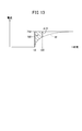
- capacitors 52, 56 and 68 are present in the first to fourth voltage converters 24a to 24d (see FIGS. 2A to 2C). Therefore, as shown in FIG. 10, even if the electric vehicle 22 is stopped and the ignition switch is turned off at the time point t4, the electric charges accumulated in the capacitors 52, 56, 68, more specifically, the equalization unit 14 and the PDU 20 A constant voltage is generated by the electric charge stored between and. Therefore, for example, in the time zone from the time point t5 to the time point t6 when the ignition switch is turned on, the control unit 46 of the control device 16 drives the switching elements 42H and 42L to the command unit 48 in step S3.
- step S4 the command unit 48 turns on the switching elements 42H and 42L by supplying the gate signal to the equalization unit 14 based on the instruction from the control unit 46.
- the electric charges of the capacitors 52, 56, and 68 are discharged in the time zone from the time point t5 to the time point t6, and the output voltage V0 can be lowered to the vicinity of 0 [V].
- the discharge process of steps S3 and S4 is executed after step S2.
- the discharge process may be executed after the ignition switch is turned on (time point t5 in FIG. 10) and before the process of step S9 (time point t7) described later.
- step S5 a voltage sensor (not shown) in the battery pack detects the voltage of the first to fourth batteries 12a to 12d (battery voltages V1 to V4). As a result, in step S6, the equalization unit 14 can grasp each battery voltage V1 to V4. In FIG. 9A, the battery voltage detected by each voltage sensor is shown as V1can to V4can. Further, the detection result of the voltage sensor is transmitted from each battery pack to the control device 16. The control device 16 transfers the detection result to the MG-ECU 18.
- the fourth batteries 12b to 12d are the batteries (residual storage unit) on the discharge side. Then, the MG-ECU 18 instructs the control device 16 to start charge / discharge control for the first to fourth batteries 12a to 12d.
- step S8 the control unit 46 of the control device 16 executes the control process for charge / discharge control based on the instruction from the MG-ECU 18, and instructs the command unit 48 to output the gate signal.
- the command unit 48 starts supplying the gate signal to the equalization unit 14 based on the instruction from the control unit 46.
- step S9 in the equalization unit 14, the switching elements 42H and 42L are driven based on the supplied gate signal, so that charge / discharge control (equalization control) is started from the time point t7. That is, in the time zone of t5 to t7 of FIG. 10, the process of steps S1 to S8 of FIG. 7 is executed as the initial process for charge / discharge control.
- step S10 the MG-ECU 18 instructs each battery pack to execute a precharge process for charging a capacitor (not shown) in the battery pack.
- step S11 each battery pack charges the capacitor based on the instruction from the MG-ECU 18.
- steps S10 and S11 the capacitors 52, 56, and 68 of the voltage converters 24a to 24d may also be charged. Further, in the present embodiment, the processes of steps S10 and S11 may be included in the initial process.
- step S12 the MG-ECU 18 instructs each battery pack to turn on a switching element (not shown) in the battery pack.
- step S13 each battery pack turns on the switching element at the time point t8 in FIG. 10 based on the instruction from the MG-ECU 18.
- the first to fourth batteries 12a to 12d and the first to fourth voltage converters 24a to 24d are electrically connected.
- step S15 charge / discharge control (equalization control) is also stopped.
- the control device 16 may be responsible for the processing of steps S1, S7, S11, and S13.
- FIG. 8 is a flowchart showing a specific method of equalization control of FIG. 7. That is, the flowchart of FIG. 8 illustrates the flow of operations of the control device 16 and the equalization unit 14 in the time zone from step S9 to step S15.
- step S21 the MG-ECU 18 or the control unit 46 determines the battery having the lowest battery voltage among the first to fourth batteries 12a to 12d as the charging side battery (reference storage unit). As shown in FIG. 9A, since the battery voltage V1 (V1can) of the first battery 12a is the lowest, the control unit 46 determines the first battery 12a as the battery on the charging side. Since the switching elements of the battery packs are off in steps S9 to S12 of FIG. 7, the first to fourth batteries 12a to 12d and the first to fourth voltage converters 24a to 24d are electrically connected. Not connected to.
- the MG-ECU 18 or the control unit 46 is the first based on the battery voltages V1 to V4 (V1can to V4can) of the first to fourth batteries 12a to 12d detected by the voltage sensors (not shown) in each battery pack.
- the battery 12a may be determined as the battery on the charging side.
- the control unit 46 sets the reference voltage Vref based on the battery voltage V1 of the first battery 12a.
- the control unit 46 sets the values (initial values) of the battery voltages V1 to V4 of the first to fourth batteries 12a to 12d used in the charging / discharging process to the reference voltage Vref, and the values of the respective battery voltages V1 to V4. Align. As a result, the voltage difference between the first to fourth batteries 12a to 12d becomes 0 [V] once.
- the first to fourth batteries 12a to 12d and the first to fourth voltage converters 24a to 24d are electrically connected, and the first to fourth voltage measuring instruments 28a are connected. It is possible to measure the battery voltages V1 to V4 of the first to fourth batteries 12a to 12d by 28d and the first to fourth currents I1 to I4 by the first to fourth current measuring instruments 26a to 26d. If so, in step S22, the control unit 46 acquires the battery voltages V1 to V4 of the first to fourth batteries 12a to 12d from the first to fourth voltage measuring instruments 28a to 28d, and the first to fourth currents. The first to fourth currents I1 to I4 are acquired from the measuring instruments 26a to 26d.
- FIG. 11 is a block diagram schematically showing the equalization unit 14
- FIG. 12 is a block diagram showing charge / discharge control in the control device 16 and the equalization unit 14.
- the “control target” is the power supply system 10 including the equalization unit 14.
- “s” in each block of “kp + kds” and “1 / s” is a complex number variable in the Laplace transform.
- control unit 46 uses the first battery 12a as the charging side battery (reference storage unit) and the second to fourth batteries 12b to 12d as the discharging side battery (residual storage unit). Therefore, the control unit 46 subtracts the second to fourth currents I2 to I4 from the first current I1.
- the control unit 46 determines which state in FIG. 6 the current charge / discharge state corresponds to based on the acquired battery voltages V1 to V4. In this case, the control unit 46 determines that the state is "3H1L" in FIG.
- the control unit 46 adds the target currents Itar2 to Itar4 to the current difference subtracted in step S23 as in the following equations (15) to (17), so that the first current I1 and the second current
- the current difference from the fourth currents I2 to I4 is calculated.
- the current differences ⁇ I2 to ⁇ I4 in the equations (15) to (17) are target currents (target operating currents) for actually controlling the first to fourth voltage converters 24a to 24d. That is, the control unit 46 can set each target operating current ⁇ I2 to ⁇ I4 by adding the target currents Itar2 to Itar4 to each current difference.
- ⁇ I2 I1-I2 + Itar2
- ⁇ I3 I1-I3 + Itar3 (16)
- ⁇ I4 I1-I4 + Itar4 (17)
- the control unit 46 uses the target operating currents (current difference) ⁇ I2 to ⁇ I4 calculated in step S24 as in the following equations (18) to (20), and uses the first battery 12a.
- the voltage difference Vd1 to Vd3 between the battery voltage V1 and the battery voltages V2 to V4 of the second to fourth batteries 12b to 12d is calculated.
- " ⁇ " is an integration symbol.
- kp and kd are fixed coefficients in feedback control.
- ⁇ I2p to ⁇ I4p are the previous target operating currents.
- Vd1 ⁇ ⁇ kp ⁇ ⁇ I2 + kd ⁇ ( ⁇ I2- ⁇ I2p) ⁇ (18)
- Vd2 ⁇ ⁇ kp ⁇ ⁇ I3 + kd ⁇ ( ⁇ I3- ⁇ I3p) ⁇ (19)
- Vd3 ⁇ ⁇ kp ⁇ ⁇ I4 + kd ⁇ ( ⁇ I4- ⁇ I4p) ⁇ (20)
- step S26 the control unit 46 calculates the step-down rates R2 to R4 using the calculated voltage differences Vd1 to Vd3.
- step S27 the command unit 48 outputs a gate signal based on the step-down rates R1 to R4 to the equalization unit 14.
- the switching elements 42H and 42L of the first to fourth voltage converters 24a to 24d are driven based on the supplied gate signal.
- step S28 the current values of the first to fourth currents I1 to I4 change depending on the voltage differences Vd1 to Vd3 as shown in FIG. 9B.
- step S29 the control unit 46 determines whether to stop the equalization control. If the step S15 has not been reached, the control unit 46 determines to continue the equalization control (step S29: NO), returns to step S22, and executes the processes of steps S22 to S29 again. Therefore, each time the processes of steps S22 to S29 are repeatedly executed, the states of the first to fourth batteries 12a to 12d are sequentially changed from "3H1L” to "2H2L", “1H3L", and "0H4L” in FIG. Switch. After that, when the step S15 is reached, the control unit 46 stops the equalization control (step S29: YES).
- FIG. 13 is a timing chart showing the effect of the control process of FIG.
- the target current Itar is set at the time point t9, and the switching elements 42H and 42L are driven by the voltage difference Vd1 based on the target current Itar, so that the second current I2 becomes the target current Itar with the passage of time after the time point t9. It rises rapidly toward.
- the time for the second current I2 to converge to the target current Itar can be shortened.
- the difference between the target current Itar and the second current I2 at an arbitrary time point t10 is the target operating current (current difference) ⁇ I2.
- the area of the portion between the time point t9 and the time point t10 surrounded by the target current Itar and the second current I2 indicates the voltage difference Vd1.
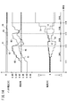
- FIG. 14 is a timing chart showing time changes of the first to fourth currents I1 to I4, the battery voltages V1 to V4, and the step-down rates R1 to R4 in the charge / discharge control in the present embodiment.
- N 4
- the battery and charge on the discharge side are charged in the order of “3H1L” ⁇ “2H2L” ⁇ “1H3L” ⁇ “0H4L”. The case where the battery on the side is switched will be described.
- the battery on the initial charging side is the fourth battery 12d
- the first to third currents I1 to I3 are discharge currents (positive currents), and the fourth current I4 is charge currents (negative currents).
- the step-down rates R1 to R3 of the first to third voltage converters 24a to 24c increase with the passage of time.
- the step-down rates R2 and R3 of the second and third voltage converters 24b and 24c reach the vicinity of 0.96 (the upper limit of the settable step-down rate)
- the value changes from "3H1L" to "2H2L". Switch.
- the first and third batteries 12a and 12c are switched to the discharge side battery, and the second and fourth batteries 12b and 12d are switched to the charge side battery. That is, the first and third currents I1 and I3 become discharge currents, and the second and fourth currents I2 and I4 become charge currents.
- the step-down rates R1 and R3 of the first and third voltage converters 24a and 24c increase with the passage of time.
- the step-down rate R2 of the second voltage converter 24b is reduced to the step-down rate R4 (0.91) of the fourth voltage converter 24d.
- the step-down rate R3 of the third voltage converter 24c reaches the vicinity of 0.96, the voltage is switched from "2H2L" to "1H3L".
- the first battery 12a is switched to the discharging side battery, and the second to fourth batteries 12b to 12d are switched to the charging side battery. That is, the first current I1 becomes the discharge current, and the second to fourth currents I2 to I4 become the charging current.
- the step-down rate R1 of the first voltage converter 24a increases with the passage of time.
- the step-down rate R3 of the third voltage converter 24c is the step-down rate R2, R4 (0.91) of the second and fourth voltage converters 24b, 24d. It drops to.
- the battery voltages V1 to V4 in the fully charged state of the first to fourth batteries 12a to 12d are set to Vi [V]
- the step-down rates R1 to R4 corresponding to the dead time Td are set to Vi [V]. It is set to 0.31.
- the charging is performed by passing a current from the discharging side battery to the charging side battery while maintaining the voltage difference between the reference charging side battery and the discharging side battery.
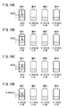
- Charge the side battery As an example, in FIG. 16A, in the state of "1H3L", the first battery 12a is the battery on the discharging side, and the second to fourth batteries 12b to 12d are the batteries on the charging side. Therefore, the initial step-down rate R1 of the first voltage converter 24a is set to 0.81, and the step-down rates R2 to R4 of the second to fourth voltage converters 24b to 24d are set (fixed) to 0.94. There is. Further, the voltage difference between the first battery 12a and the second to fourth batteries 12b to 12d is set to Vd [V].
- FIG. 17 is a timing chart showing time changes in vehicle speed, current, and SOC when the power supply system 10 according to the present embodiment is mounted on the electric vehicle 22.
- the electric vehicle 22 started in the time zone before the time point t15 stops in the time zone from the time point t15 to the time point t16, and then accelerates from the time point t16. After that, the electric vehicle 22 cruises from the time point t17, changes from the time point t18 to the deceleration running, and stops at the time point t19.
- the electric vehicle 22 is stopped (time zone from t15 to t16, time zone after time point t19) and during cruise running (a part of t17 to t18). During this time period), charging and discharging are performed between the battery on the discharging side and the battery on the charging side.
- FIG. 17 the current and SOC flowing from the battery on the discharging side are shown by a broken line, and the current and SOC flowing into the battery on the charging side are shown by a solid line.
- the plurality of rechargeable batteries 12a to 12d storage unit
- the input side 34 are connected to the plurality of batteries 12a to 12d
- the output side 36 are connected in parallel with each other.
- a plurality of voltage converters 24a to 24d that convert the voltages V1 to V4 of the plurality of batteries 12a to 12d connected to the input side 34 with an arbitrary transformation rate Tr and output the converted voltage V0 to the output side 36.
- a power supply system 10 which is connected to the input side 34 of a plurality of voltage converters 24a to 24d and includes a plurality of current measuring instruments 26a to 26d for measuring currents I1 to I4 flowing from the plurality of batteries 12a to 12d to the input side 34. And the control method.
- the power supply system 10 determines at least one of the plurality of batteries 12a to 12d as the charging side battery (reference storage unit) and the remaining battery as the discharging side battery (residual storage unit). Based on the currents I1 to I4 measured by the power storage unit determination unit (MG-ECU 18, control unit 46) and the plurality of current measuring instruments 26a to 26d, the current flowing from the discharge side battery and the current flowing from the charging side battery A current difference determination unit (control unit 46) that determines the current difference between the two, and a transformation rate determination unit (control) that determines the transformation rate Tr of the voltage converter connected to the battery on the discharge side based on the determined current difference. It has a part 46) and.
- At least one of the plurality of batteries 12a to 12d is determined to be the battery on the charging side by using the MG-ECU 18 or the control unit 46, and the remaining battery is the battery on the discharging side.
- the step of determining the battery step S7
- the currents I1 to I4 measured by the plurality of current measuring instruments 26a to 26d using the control unit 46 the current flowing from the battery on the discharging side and the battery on the charging side
- a step of determining the current difference from the flowing current steps S23 and S24
- a step of determining the transformation rate Tr of the voltage converter connected to the battery on the discharging side based on the determined current difference by the control unit 46.
- the MG-ECU 18 or the control unit 46 determines the battery having the lowest voltage among the plurality of batteries 12a to 12d as the battery on the charging side, and the remaining battery as the battery on the discharging side. Thereby, the battery on the discharging side and the battery on the charging side can be efficiently determined.
- the control unit 46 subtracts the current flowing from the battery on the charging side by the current flowing from the battery on the discharging side, and calculates the current difference by adding the subtracted current and the target current Itar. By such feedback control, charge / discharge control can be performed while avoiding an excessive current flowing from each of the batteries 12a to 12d.
- the target current Itar is a current value set according to the number of the plurality of batteries 12a to 12d, the number of batteries on the charging side, or the total current flowing from the plurality of batteries 12a to 12d. Thereby, the target current can be appropriately set according to the number of batteries 12a to 12d.
- control unit 46 calculates the voltage difference between the battery voltage of the battery on the charging side and the battery voltage of the battery on the discharging side based on the current difference, and connects to the battery on the discharging side using the calculated voltage difference.
- the transformation rate Tr of the voltage converter to be used is determined. In this way, since the transformation rate Tr is determined using the voltage difference reflecting the current difference, it is possible to prevent the current flowing from each of the batteries 12a to 12d from becoming excessive, and the deterioration of the batteries 12a to 12d occurs. Can be suppressed efficiently.
Landscapes
- Engineering & Computer Science (AREA)
- Power Engineering (AREA)
- Physics & Mathematics (AREA)
- General Physics & Mathematics (AREA)
- Charge And Discharge Circuits For Batteries Or The Like (AREA)
- Secondary Cells (AREA)
Abstract
Description
本実施形態に係る電源システム10は、図1に示すように、複数のバッテリ12a~12d(蓄電部)と、均等化ユニット14と、制御装置16と、モータジェネレータECU(MG-ECU)18と、パワードライブユニット(PDU)20とを有する。なお、図1では、4個のバッテリ12a~12d(以下、第1~第4バッテリ12a~12dともいう。)が配置される場合を図示している。電源システム10では、少なくとも2個のバッテリが配置されていればよい。また、電源システム10は、例えば、二輪車、四輪車等の電動車両22の電源システムに適用される。
図2A~図2Cは、図1の第1~第4電圧変換器24a~24dの具体例を示す回路図である。第1~第4電圧変換器24a~24dは、例えば、降圧型若しくは昇降圧型(図2A参照)、降圧型(図2B参照)、又は、昇降圧型(図2C参照)のDC/DCコンバータである。これらのDC/DCコンバータの構成及び動作は、周知であるため、ここでは、図2A~図2Cの回路図における各構成要素の接続関係について簡単に説明する。
T=U+D+Td×2 (1)
R=Vout/Vin (2)
U=T×R (3)
D=T×(1-R) (4)
<3.1 本実施形態の充放電の手法の概要>
次に、本実施形態に係る電源システム10及びその制御方法の特徴的な機能(以下、本実施形態の特徴的な機能ともいう。)について、図4~図17を参照しながら説明する。本実施形態の特徴的な機能とは、電圧又はSOCの異なる第1~第4バッテリ12a~12dを互いに並列接続し、電圧又はSOCが互いに均等となるように第1~第4バッテリ12a~12d間に第1~第4電流I1~I4を流して充放電を行う場合に、第1~第4バッテリ12a~12dから入力側34に流れる第1~第4電流I1~I4を制御装置16にフィードバックし、制御装置16の制御部46が、充電側のバッテリ(基準蓄電部)から流れる電流と、放電側のバッテリ(残余蓄電部)から流れる電流との電流差を決定した後、決定した電流差が小さくなるような降圧率Rを決定し、決定した降圧率Rで第1~第4電圧変換器24a~24dを制御することにより、各バッテリ12a~12dの劣化を回避しつつ、各バッテリ12a~12dの電圧又はSOCの均等化を図るというものである。
I1=It/2+Vd1/(4×r) (5)
I2=It/2-Vd1/(4×r) (6)
I1=It/3+(Vd1+Vd2)/(6×r) (7)
I2=It/3+(-2×Vd1+Vd2)/(6×r)(8)
I3=It/3+(Vd1-2×Vd2)/(6×r) (9)
I1=It/4+(Vd1+Vd2+Vd3)/(8×r)
(10)
I2=It/4+(-3×Vd1+Vd2+Vd3)/(8×r)
(11)
I3=It/4+(Vd1-3×Vd2+Vd3)/(8×r)
(12)
I4=It/4+(Vd1+Vd2-3×Vd3)/(8×r)
(13)
図7は、本実施形態に係る電源システム10を電動車両22に適用した場合、より具体的には、モータ44を電動車両22の車輪の駆動源に用いる場合の第1~第4バッテリ12a~12dに対する充放電制御のシーケンス図である。図8は、図7の充放電制御において、均等化ユニット14及び制御装置16の動作を示すフローチャートである。この説明では、図9A及び図9Bに示すように、第1バッテリ12aのバッテリ電圧V1が最も低く、第1~第4バッテリ12a~12dの順にバッテリ電圧V1~V4が高い場合の充放電制御について説明する。
Vref=R1×(最も低いバッテリ電圧(V1)) (14)
ΔI2=I1-I2+Itar2 (15)
ΔI3=I1-I3+Itar3 (16)
ΔI4=I1-I4+Itar4 (17)
Vd1=∫{kp×ΔI2+kd×(ΔI2-ΔI2p)}(18)
Vd2=∫{kp×ΔI3+kd×(ΔI3-ΔI3p)}(19)
Vd3=∫{kp×ΔI4+kd×(ΔI4-ΔI4p)}(20)
次に、本実施形態において、降圧率Rを考慮する必要性について、図14~図16Dを参照しながら説明する。図14は、本実施形態における充放電制御での第1~第4電流I1~I4、各バッテリ電圧V1~V4及び降圧率R1~R4の時間変化を示すタイミングチャートである。ここでは、図6に示すように、N=4であり、時点t11、t12、t13、t14において、「3H1L」→「2H2L」→「1H3L」→「0H4L」の順に、放電側のバッテリと充電側のバッテリとが切り換わる場合について説明する。
図17は、本実施形態に係る電源システム10を電動車両22に搭載した場合における車速、電流及びSOCの時間変化を示したタイミングチャートである。この場合、時点t15前の時間帯に起動した電動車両22は、時点t15から時点t16の時間帯で停車した後、時点t16から加速走行を行う。その後、電動車両22は、時点t17からクルーズ走行を行い、時点t18から減速走行に変化し、時点t19で停車する。
以上説明したように、本実施形態は、充放電可能な複数のバッテリ12a~12d(蓄電部)と、入力側34が複数のバッテリ12a~12dに接続され、出力側36が互いに並列接続され、入力側34に接続されている複数のバッテリ12a~12dの電圧V1~V4を任意の変圧率Trで変換し、変換した電圧V0を出力側36に出力する複数の電圧変換器24a~24dと、複数の電圧変換器24a~24dの入力側34に接続され、複数のバッテリ12a~12dから入力側34に流れる電流I1~I4を計測する複数の電流計測器26a~26dとを備える電源システム10、及び、その制御方法である。
Claims (6)
- 充放電可能な複数の蓄電部(12a~12d)と、
入力側(34)が複数の前記蓄電部に接続され、出力側(36)が互いに並列接続され、前記入力側に接続されている複数の前記蓄電部の電圧(V1~V4)を任意の変圧率(Tr)で変換し、変換した前記電圧(V0)を前記出力側に出力する複数の電圧変換器(24a~24d)と、
複数の前記電圧変換器の入力側に接続され、複数の前記蓄電部から前記入力側に流れる電流(I1~I4)を計測する複数の電流計測器(26a~26d)と、
を備える電源システム(10)において、
複数の前記蓄電部のうち、少なくとも1つの前記蓄電部を充電側の基準蓄電部に決定し、残余の前記蓄電部を放電側の残余蓄電部に決定する蓄電部決定部(18、46)と、
複数の前記電流計測器が計測した前記電流に基づいて、前記残余蓄電部から流れる前記電流と前記基準蓄電部から流れる前記電流との電流差を決定する電流差決定部(46)と、
決定した前記電流差に基づいて、前記残余蓄電部に接続される前記電圧変換器の変圧率を決定する変圧率決定部(46)と、
をさらに備える、電源システム。 - 請求項1記載の電源システムにおいて、
前記蓄電部決定部は、複数の前記蓄電部のうち、最も低い電圧の前記蓄電部を前記基準蓄電部に決定し、残余の前記蓄電部を前記残余蓄電部に決定する、電源システム。 - 請求項1又は2記載の電源システムにおいて、
前記電流差決定部は、前記基準蓄電部から流れる電流を前記残余蓄電部から流れる電流で減算し、減算後の前記電流と目標電流(Itar)とを加算することにより前記電流差を算出する、電源システム。 - 請求項3記載の電源システムにおいて、
前記目標電流は、複数の前記蓄電部の個数、前記基準蓄電部の個数、又は、複数の前記蓄電部から流れる前記電流の総和に応じて設定された電流値である、電源システム。 - 請求項1~4のいずれか1項に記載の電源システムにおいて、
前記変圧率決定部は、前記電流差に基づいて、前記基準蓄電部の電圧と前記残余蓄電部の電圧との電圧差を算出し、算出した前記電圧差を用いて、前記残余蓄電部に接続される前記電圧変換器の変圧率を決定する、電源システム。 - 充放電可能な複数の蓄電部(12a~12d)と、
入力側(34)が複数の前記蓄電部に接続され、出力側(36)が互いに並列接続され、前記入力側に接続されている複数の前記蓄電部の電圧(V1~V4)を任意の変圧率(Tr)で変換し、変換した前記電圧(V0)を前記出力側に出力する複数の電圧変換器(24a~24d)と、
複数の前記電圧変換器の入力側に接続され、複数の前記蓄電部から前記入力側に流れる電流(I1~I4)を計測する複数の電流計測器(26a~26d)と、
を備える電源システム(10)の制御方法において、
蓄電部決定部(18、46)を用いて、複数の前記蓄電部のうち、少なくとも1つの前記蓄電部を充電側の基準蓄電部に決定し、残余の前記蓄電部を放電側の残余蓄電部に決定するステップ(S7)と、
電流差決定部(46)を用いて、複数の前記電流計測器が計測した前記電流に基づいて、前記残余蓄電部から流れる前記電流と前記基準蓄電部から流れる前記電流との電流差を決定するステップ(S23、S24)と、
変圧率決定部(46)を用いて、決定した前記電流差に基づいて、前記残余蓄電部に接続される前記電圧変換器の変圧率を決定するステップ(S26)と、
を有する、電源システムの制御方法。
Priority Applications (4)
| Application Number | Priority Date | Filing Date | Title |
|---|---|---|---|
| JP2021558438A JP7147080B2 (ja) | 2019-11-20 | 2020-11-19 | 電源システム及びその制御方法 |
| CN202080080813.XA CN114731055B (zh) | 2019-11-20 | 2020-11-19 | 电源系统及其控制方法 |
| US17/778,029 US11646599B2 (en) | 2019-11-20 | 2020-11-19 | Power supply system and method for controlling same |
| EP20889216.6A EP4064517B1 (en) | 2019-11-20 | 2020-11-19 | Power supply system and method for controlling same |
Applications Claiming Priority (2)
| Application Number | Priority Date | Filing Date | Title |
|---|---|---|---|
| JP2019209519 | 2019-11-20 | ||
| JP2019-209519 | 2019-11-20 |
Publications (1)
| Publication Number | Publication Date |
|---|---|
| WO2021100799A1 true WO2021100799A1 (ja) | 2021-05-27 |
Family
ID=75980117
Family Applications (1)
| Application Number | Title | Priority Date | Filing Date |
|---|---|---|---|
| PCT/JP2020/043159 Ceased WO2021100799A1 (ja) | 2019-11-20 | 2020-11-19 | 電源システム及びその制御方法 |
Country Status (5)
| Country | Link |
|---|---|
| US (1) | US11646599B2 (ja) |
| EP (1) | EP4064517B1 (ja) |
| JP (1) | JP7147080B2 (ja) |
| CN (1) | CN114731055B (ja) |
| WO (1) | WO2021100799A1 (ja) |
Cited By (1)
| Publication number | Priority date | Publication date | Assignee | Title |
|---|---|---|---|---|
| JP2023027996A (ja) * | 2021-08-18 | 2023-03-03 | 矢崎総業株式会社 | 電源制御装置、電源装置、及び電源制御方法 |
Families Citing this family (4)
| Publication number | Priority date | Publication date | Assignee | Title |
|---|---|---|---|---|
| US12555991B2 (en) * | 2017-06-26 | 2026-02-17 | Swidget Corporation | Configurable electrical receptacles |
| US12463438B2 (en) * | 2020-12-23 | 2025-11-04 | Samsung Electronics Co., Ltd. | Wearable electronic device including multiple batteries and method for operating the same |
| KR102882635B1 (ko) * | 2021-01-13 | 2025-11-05 | 주식회사 엘지에너지솔루션 | 배터리 뱅크 전력 제어 장치 및 방법 |
| CN113765177B (zh) * | 2021-07-30 | 2024-06-11 | 华为数字能源技术有限公司 | 一种电池模块和充电系统 |
Citations (4)
| Publication number | Priority date | Publication date | Assignee | Title |
|---|---|---|---|---|
| JP2008220084A (ja) * | 2007-03-06 | 2008-09-18 | Toyota Motor Corp | 車両の電源装置および車両の電源装置の制御方法 |
| JP2016025791A (ja) | 2014-07-23 | 2016-02-08 | 本田技研工業株式会社 | 蓄電システム |
| JP2016063717A (ja) * | 2014-09-22 | 2016-04-25 | 住友電気工業株式会社 | 蓄電システム |
| JP2019193475A (ja) * | 2018-04-26 | 2019-10-31 | 京セラ株式会社 | 蓄電装置、蓄電装置の制御装置及び蓄電装置の制御方法 |
Family Cites Families (11)
| Publication number | Priority date | Publication date | Assignee | Title |
|---|---|---|---|---|
| US3667025A (en) * | 1971-06-21 | 1972-05-30 | Gen Motors Corp | Dual voltage system |
| JP4984754B2 (ja) | 2006-09-04 | 2012-07-25 | トヨタ自動車株式会社 | 電源システムおよびそれを備えた車両 |
| JP4450004B2 (ja) * | 2007-03-30 | 2010-04-14 | トヨタ自動車株式会社 | 電源回路の制御装置および制御方法 |
| JP5359214B2 (ja) * | 2008-11-19 | 2013-12-04 | 株式会社明電舎 | 直流電源のチョッパ制御方法および前記直流電源のチョッパ制御方法を用いた移動車両 |
| US8598734B2 (en) * | 2009-05-08 | 2013-12-03 | Toyota Jidosha Kabushiki Kaisha | Power supply system and vehicle equipped with the same |
| WO2013031559A1 (ja) * | 2011-08-30 | 2013-03-07 | 三洋電機株式会社 | バッテリシステム、電動車両、移動体、電力貯蔵装置および電源装置 |
| US9209639B2 (en) * | 2012-07-13 | 2015-12-08 | Panasonic Intellectual Property Management Co., Ltd. | Storage battery system and method of controlling the same |
| JP6133817B2 (ja) * | 2014-05-14 | 2017-05-24 | 本田技研工業株式会社 | 2電源システム及び電動車両 |
| JP6518603B2 (ja) * | 2016-02-24 | 2019-05-22 | 本田技研工業株式会社 | 電源装置、機器及び制御方法 |
| JP6652428B2 (ja) * | 2016-03-29 | 2020-02-26 | 本田技研工業株式会社 | 電力供給システム及び輸送機器、並びに、電力供給システムの制御方法 |
| JP6652427B2 (ja) * | 2016-03-29 | 2020-02-26 | 本田技研工業株式会社 | 電力供給システム及び輸送機器 |
-
2020
- 2020-11-19 JP JP2021558438A patent/JP7147080B2/ja active Active
- 2020-11-19 US US17/778,029 patent/US11646599B2/en active Active
- 2020-11-19 CN CN202080080813.XA patent/CN114731055B/zh active Active
- 2020-11-19 WO PCT/JP2020/043159 patent/WO2021100799A1/ja not_active Ceased
- 2020-11-19 EP EP20889216.6A patent/EP4064517B1/en active Active
Patent Citations (4)
| Publication number | Priority date | Publication date | Assignee | Title |
|---|---|---|---|---|
| JP2008220084A (ja) * | 2007-03-06 | 2008-09-18 | Toyota Motor Corp | 車両の電源装置および車両の電源装置の制御方法 |
| JP2016025791A (ja) | 2014-07-23 | 2016-02-08 | 本田技研工業株式会社 | 蓄電システム |
| JP2016063717A (ja) * | 2014-09-22 | 2016-04-25 | 住友電気工業株式会社 | 蓄電システム |
| JP2019193475A (ja) * | 2018-04-26 | 2019-10-31 | 京セラ株式会社 | 蓄電装置、蓄電装置の制御装置及び蓄電装置の制御方法 |
Non-Patent Citations (1)
| Title |
|---|
| See also references of EP4064517A4 |
Cited By (3)
| Publication number | Priority date | Publication date | Assignee | Title |
|---|---|---|---|---|
| JP2023027996A (ja) * | 2021-08-18 | 2023-03-03 | 矢崎総業株式会社 | 電源制御装置、電源装置、及び電源制御方法 |
| CN115912532A (zh) * | 2021-08-18 | 2023-04-04 | 矢崎总业株式会社 | 电源控制装置、电源装置及电源控制方法 |
| JP7522706B2 (ja) | 2021-08-18 | 2024-07-25 | 矢崎総業株式会社 | 電源制御装置、電源装置、及び電源制御方法 |
Also Published As
| Publication number | Publication date |
|---|---|
| US20220416562A1 (en) | 2022-12-29 |
| US11646599B2 (en) | 2023-05-09 |
| CN114731055B (zh) | 2025-08-29 |
| JPWO2021100799A1 (ja) | 2021-05-27 |
| EP4064517A1 (en) | 2022-09-28 |
| JP7147080B2 (ja) | 2022-10-04 |
| EP4064517B1 (en) | 2024-07-03 |
| EP4064517A4 (en) | 2023-04-12 |
| CN114731055A (zh) | 2022-07-08 |
Similar Documents
| Publication | Publication Date | Title |
|---|---|---|
| JP7147080B2 (ja) | 電源システム及びその制御方法 | |
| US20220029428A1 (en) | Power supply system | |
| EP1801960B1 (en) | Bi-directional DC-DC converter and control method | |
| JP5374210B2 (ja) | Dc/dcコンバータおよびそれを用いた給電システム | |
| JP2020519223A (ja) | 分散型バッテリ、バッテリ制御方法、及び電気自動車 | |
| CN111277133B (zh) | 用于控制车辆的低压直流至直流转换器的装置和方法 | |
| US9868358B2 (en) | Power conversion system suppressing reduction in conversion efficiency | |
| JP4984754B2 (ja) | 電源システムおよびそれを備えた車両 | |
| US9755439B2 (en) | Battery state control circuit, battery state control device, and battery pack | |
| CN103650312A (zh) | 电源系统 | |
| CN110192336A (zh) | 电力转换系统的控制装置、控制系统 | |
| CN104917388A (zh) | 电力转换装置及其起动方法 | |
| KR20180071965A (ko) | 전기 자동차용의 전원 시스템 | |
| JP2012125040A (ja) | 電力変換回路システム | |
| US20130038270A1 (en) | Secondary battery output power controller | |
| CN112531860A (zh) | 对车辆的电池充电的系统及用于控制该系统的方法 | |
| CN104980031B (zh) | 电力转换装置和控制该电力转换装置的方法 | |
| JP2013169051A (ja) | 電池電圧均等化装置および方法 | |
| US9627978B2 (en) | Circuit arrangement and method for ascertaining switching times for a DC-DC voltage converter | |
| JP2010206933A (ja) | 電力供給装置 | |
| JP2017099080A (ja) | 電池の接続方法 | |
| JPWO2019220915A1 (ja) | 電源システム | |
| JP5429656B1 (ja) | 直流電源装置 | |
| JP2014121196A (ja) | 二次電池の充電装置 | |
| WO2022234784A1 (ja) | 電力変換装置 |
Legal Events
| Date | Code | Title | Description |
|---|---|---|---|
| 121 | Ep: the epo has been informed by wipo that ep was designated in this application |
Ref document number: 20889216 Country of ref document: EP Kind code of ref document: A1 |
|
| ENP | Entry into the national phase |
Ref document number: 2021558438 Country of ref document: JP Kind code of ref document: A |
|
| NENP | Non-entry into the national phase |
Ref country code: DE |
|
| ENP | Entry into the national phase |
Ref document number: 2020889216 Country of ref document: EP Effective date: 20220620 |
|
| WWG | Wipo information: grant in national office |
Ref document number: 202080080813.X Country of ref document: CN |