WO2021100865A1 - 位置推定方法及び位置推定システム - Google Patents
位置推定方法及び位置推定システム Download PDFInfo
- Publication number
- WO2021100865A1 WO2021100865A1 PCT/JP2020/043476 JP2020043476W WO2021100865A1 WO 2021100865 A1 WO2021100865 A1 WO 2021100865A1 JP 2020043476 W JP2020043476 W JP 2020043476W WO 2021100865 A1 WO2021100865 A1 WO 2021100865A1
- Authority
- WO
- WIPO (PCT)
- Prior art keywords
- magnetic
- distribution
- road surface
- vehicle
- position estimation
- Prior art date
- Legal status (The legal status is an assumption and is not a legal conclusion. Google has not performed a legal analysis and makes no representation as to the accuracy of the status listed.)
- Ceased
Links
Images









Classifications
-
- G—PHYSICS
- G08—SIGNALLING
- G08G—TRAFFIC CONTROL SYSTEMS
- G08G1/00—Traffic control systems for road vehicles
- G08G1/01—Detecting movement of traffic to be counted or controlled
- G08G1/042—Detecting movement of traffic to be counted or controlled using inductive or magnetic detectors
-
- G—PHYSICS
- G01—MEASURING; TESTING
- G01C—MEASURING DISTANCES, LEVELS OR BEARINGS; SURVEYING; NAVIGATION; GYROSCOPIC INSTRUMENTS; PHOTOGRAMMETRY OR VIDEOGRAMMETRY
- G01C21/00—Navigation; Navigational instruments not provided for in groups G01C1/00 - G01C19/00
- G01C21/26—Navigation; Navigational instruments not provided for in groups G01C1/00 - G01C19/00 specially adapted for navigation in a road network
- G01C21/28—Navigation; Navigational instruments not provided for in groups G01C1/00 - G01C19/00 specially adapted for navigation in a road network with correlation of data from several navigational instruments
-
- G—PHYSICS
- G01—MEASURING; TESTING
- G01C—MEASURING DISTANCES, LEVELS OR BEARINGS; SURVEYING; NAVIGATION; GYROSCOPIC INSTRUMENTS; PHOTOGRAMMETRY OR VIDEOGRAMMETRY
- G01C21/00—Navigation; Navigational instruments not provided for in groups G01C1/00 - G01C19/00
- G01C21/04—Navigation; Navigational instruments not provided for in groups G01C1/00 - G01C19/00 by terrestrial means
- G01C21/08—Navigation; Navigational instruments not provided for in groups G01C1/00 - G01C19/00 by terrestrial means involving use of the magnetic field of the earth
-
- G—PHYSICS
- G01—MEASURING; TESTING
- G01V—GEOPHYSICS; GRAVITATIONAL MEASUREMENTS; DETECTING MASSES OR OBJECTS; TAGS
- G01V3/00—Electric or magnetic prospecting or detecting; Measuring magnetic field characteristics of the earth, e.g. declination, deviation
- G01V3/15—Electric or magnetic prospecting or detecting; Measuring magnetic field characteristics of the earth, e.g. declination, deviation specially adapted for use during transport, e.g. by a person, vehicle or boat
- G01V3/165—Electric or magnetic prospecting or detecting; Measuring magnetic field characteristics of the earth, e.g. declination, deviation specially adapted for use during transport, e.g. by a person, vehicle or boat operating with magnetic or electric fields produced or modified by the object or by the detecting device
-
- G—PHYSICS
- G05—CONTROLLING; REGULATING
- G05D—SYSTEMS FOR CONTROLLING OR REGULATING NON-ELECTRIC VARIABLES
- G05D1/00—Control of position, course, altitude or attitude of land, water, air or space vehicles, e.g. using automatic pilots
- G05D1/02—Control of position or course in two dimensions
- G05D1/021—Control of position or course in two dimensions specially adapted to land vehicles
- G05D1/0259—Control of position or course in two dimensions specially adapted to land vehicles using magnetic or electromagnetic means
- G05D1/0261—Control of position or course in two dimensions specially adapted to land vehicles using magnetic or electromagnetic means using magnetic plots
-
- G—PHYSICS
- G05—CONTROLLING; REGULATING
- G05D—SYSTEMS FOR CONTROLLING OR REGULATING NON-ELECTRIC VARIABLES
- G05D1/00—Control of position, course, altitude or attitude of land, water, air or space vehicles, e.g. using automatic pilots
- G05D1/02—Control of position or course in two dimensions
- G05D1/021—Control of position or course in two dimensions specially adapted to land vehicles
- G05D1/0268—Control of position or course in two dimensions specially adapted to land vehicles using internal positioning means
- G05D1/0274—Control of position or course in two dimensions specially adapted to land vehicles using internal positioning means using mapping information stored in a memory device
Definitions
- the present invention relates to a position estimation method and a position estimation system for estimating the position of the own vehicle on a map.
- Patent Document 1 various technologies for supporting vehicle driving such as lane-following driving and automatic driving have been proposed (see, for example, Patent Document 1), and technological development for realization is active.
- advanced driving support such as automatic driving
- a highly accurate three-dimensional map showing the driving environment has been proposed and used.
- Patent Document 2 describes a highly accurate three-dimensional map including three-dimensional position information such as lane marks and curbs.
- Such a high-precision three-dimensional map is effective for grasping the three-dimensional structure of the driving environment with high accuracy. Understanding the three-dimensional structure of the driving environment with high accuracy is indispensable for realizing lane-following driving and autonomous driving.
- the present invention has been made in view of the above-mentioned conventional problems, and an object of the present invention is to provide a method and a system for estimating the position of the own vehicle on a map.
- One aspect of the present invention is a position estimation method for a vehicle including a magnetic sensor that measures magnetism acting from a road surface forming the surface of a track to estimate the position of the own vehicle.
- the magnetic measurement process for acquiring the magnetic measurement value by the magnetic sensor and A magnetic distribution generation process that generates a measured magnetic distribution that represents the distribution of magnetic data based on the magnetic measurement values acquired by the magnetic measurement process, and By referring to a map associated with the road surface magnetic distribution representing the distribution of magnetic data based on the magnetic charge of each point on the road surface, a region of the road surface magnetic distribution corresponding to the measured magnetic distribution is specified, and the measurement is performed.
- the position estimation method includes a position estimation process for estimating the position of the own vehicle based on the position on the map of the region corresponding to the magnetic distribution.
- One aspect of the present invention is a position estimation system in which a vehicle including a magnetic sensor for measuring magnetism acting from the road surface side forming the surface of a track estimates its own vehicle position.
- a storage unit that stores a map associated with the road surface magnetic distribution, which is the distribution of magnetic data based on the magnetic charge of each point on the road surface.
- a magnetic distribution generator that acquires a magnetic measurement value by the magnetic sensor and generates a measurement magnetic distribution that is a distribution of magnetic data based on the magnetic measurement value.
- a region corresponding to the measured magnetic distribution is specified, and the vehicle position is based on the position of the region corresponding to the measured magnetic distribution on the map. It is in a position estimation system that includes a position estimation unit that estimates.
- the present invention is an invention for estimating the position of the own vehicle on a map.
- the map to which the road surface magnetic distribution is associated can be collated with the measured magnetic distribution acquired on the vehicle side. If a region corresponding to the measured magnetic distribution can be specified in the road surface magnetic distribution, the position of the own vehicle can be estimated based on the position on the map of the region corresponding to the measured magnetic distribution.
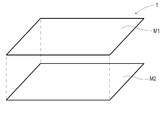
- FIG. 1 The figure explaining the structure of the map in Example 1.
- FIG. 1 The front view of the vehicle in Example 1.
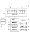
- the block diagram which shows the structure which the vehicle has in Example 1.
- the flow chart which shows the procedure of the position estimation method in Example 1.
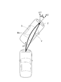
- FIG. The figure which illustrates the motion estimation result when the vehicle is a cornering state in Example 1.
- FIG. 1 The explanatory view of the collation process between the conversion magnetic distribution based on the road surface magnetic distribution and the measurement magnetic distribution in Example 1.
- FIG. The figure which illustrates the collation range of the one-dimensional magnetic distribution in Example 1.
- the flow chart which shows the procedure of the position estimation method in Example 2.
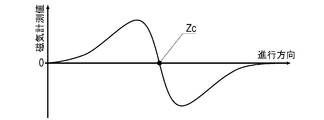
- FIG. The explanatory view which illustrates the change of the magnetic measurement value in the traveling direction when passing through a magnetic marker in Example 2.
- FIG. The explanatory view which illustrates the distribution of the magnetic measurement value in the vehicle width direction by the magnetic sensor Cn arranged in the vehicle width direction in Example 2.
- FIG. The figure which illustrates the measurement magnetic distribution in which the position of the magnetic marker is plotted in Example 2.
- FIG. 2 The explanatory view of the collation processing of the measurement magnetic distribution in Example 2.
- FIG. 3 The perspective view which shows the magnetic marker which attached the RF-ID tag in Example 3.
- FIG. 3 The block diagram which shows the structure which the vehicle has in Example 3.
- the magnetic gradient can be obtained, for example, by the difference between two magnetic charges or magnetic measurement values on the road surface.
- the magnetic gradient can be obtained from the difference between the magnetic measurement values of adjacent magnetic sensors.
- the magnetic gradient suppresses magnetic components that act uniformly or nearly uniformly on the magnetic sensor. Therefore, in the magnetic gradient, the magnetic component acting from the magnetic source existing relatively far away is suppressed, and the magnetic component acting from the magnetic source such as the road surface existing relatively close is relatively emphasized. .. Therefore, if a magnetic gradient is adopted as the magnetic data that constitutes the road surface magnetic distribution and the measured magnetic distribution, the influence of surrounding vehicles, guardrails, signboards, and other magnetic sources and the influence of geomagnetism can be suppressed, and the influence of geomagnetism can be suppressed.
- the distribution reflects magnetism with high accuracy.
- Example 1 This example is an example relating to a position estimation method and a position estimation system 1S for accurately estimating the position of the own vehicle on a map. This content will be described with reference to FIGS. 1 to 12.
- the position estimation system 1S is a system that estimates the position of the own vehicle (own vehicle position) by using the distribution (magnetic distribution) of magnetic data based on the magnetic amount of each point on the road surface 100S (FIG. 2).
- the road surface 100S forming the surface of the road (an example of a runway) 100 is formed of a pavement material. It is inevitable that magnetic materials such as metal powder will be mixed into the pavement material. Many of the manholes and bridge joints (expansion and contraction devices) exposed on the road surface 100S are made of metal and can be a magnetic source. Therefore, the magnitude of the magnetism at each point on the road surface 100S is not constant and varies in magnitude.
- the magnetic distribution of the road surface 100S is similar to, for example, the variation in brightness of each point of the image obtained by photographing the road surface 100S from directly above with an imaging camera, that is, the brightness distribution and the mode of distribution are similar.
- the target physical quantity of the magnetic distribution of the road surface 100S is different from the luminance distribution
- the luminance distribution represents the magnetic pattern of the road surface 100S in the same manner as the luminance distribution represents the luminance pattern of the road surface 100S.
- the position estimation system 1S of this example estimates the position of the own vehicle by using the road surface magnetic distribution, which is the distribution of magnetic data based on the magnetic charge of each point of the road surface 100S.
- the magnetic charge itself is used as magnetic data. Therefore, the road surface magnetic distribution of this example is the distribution of magnetic data which is the magnetic charge of each point of the road surface 100S.
- the road surface magnetic distribution M2 is associated with the structural map M1 showing the road structure and the like.
- the structural map M1 and the road surface magnetic distribution M2 are associated with each other by position data representing an absolute position.
- the position on the road surface magnetic distribution M2 uniquely corresponds to the position on the structural map M1. If a region having the same distribution pattern as the magnetic distribution of the road surface 100S measured by the vehicle can be specified in the road surface magnetic distribution M2, the position of the own vehicle on the map 1 can be estimated based on the position of the region.
- This position estimation system 1S can be combined with, for example, an automatic driving system (not shown) for realizing automatic driving of a vehicle.
- the automatic driving system grasps the structure of the driving environment ahead by using the own vehicle position estimated by the position estimation system 1S. For example, if a three-dimensional map is adopted, the three-dimensional structure of the driving environment in front can be grasped, and highly accurate automatic driving can be realized.
- the road surface magnetic distribution M2 which represents the distribution of magnetic data that is the amount of magnetism at each point on the road surface 100S, includes, for example, a high-precision positioning system including an RTK-GPS unit and an IMU, and magnetic sensors arranged along the vehicle width direction. It can be generated by using a measurement vehicle (not shown) including the magnetic measurement unit.
- RTK-GPS RealTimeKinematic Global Positioning System
- IMU Inertial Measurement Unit
- IMU Inertial Measurement Unit
- the IMU is equipped with an electronic compass for measuring the direction, an acceleration sensor, a gyro sensor, and the like, and calculates a relative position with respect to a reference position.
- an electronic compass for measuring the direction
- an acceleration sensor for measuring the direction
- a gyro sensor for measuring the direction
- a relative position with respect to a reference position By using the relative position estimated by the IMU, highly accurate positioning can be realized even in a valley or tunnel of a building where GPS radio waves are unstable.
- the magnetic measurement unit should be attached to the vehicle via a mechanism that automatically adjusts the height with the road surface 100S to a constant level. If the height of the magnetic measurement unit from the road surface 100S is constant, the magnetic distribution at each point on the road surface 100S can be measured with high accuracy.
- a measurement vehicle not shown
- high-precision positioning system such as an RTK-GPS unit or IMU
- high-precision position data is added to the magnetic data, which is the magnetic amount of each point of the road surface 100S measured by the magnetic measurement unit.
- the vehicle 5 constituting the position estimation system 1S is a map database (map DB) that stores a sensor array 2 in which a plurality of magnetic sensors Cn are arranged in the vehicle width direction and a map 1 (FIG. 1).
- Map DB map database
- the control unit 32 includes a GPS unit 351 that executes positioning calculations using GPS satellites, a steering steering angle sensor 353 that detects the steering direction, a vehicle speed sensor 355, and a height for measuring the height of the sensor array 2.
- a sensor 357 or the like is connected.
- the map DB 40 is an example of a storage unit that stores the map 1 to which the road surface magnetic distribution M2 is associated.
- the height sensor 357 is an ultrasonic type distance measuring sensor.
- the height sensor 357 is attached in the vicinity of the sensor array 2 so that the height of the sensor array 2 from the road surface 100S can be measured.
- the height measured by the height sensor 357 is treated as the mounting height of the magnetic sensor Cn. It is also possible to arrange height sensors at two or more locations in the vehicle width direction so as to cope with the inclination of the vehicle body due to the roll. In this case, the mounting heights of the plurality of magnetic sensors Cn having different positions in the vehicle width direction can be grasped, and the inclination of the vehicle body can be specified.
- the height sensor 357 may be a laser type distance measuring sensor.
- the sensor array 2 is an elongated rod-shaped unit including 15 magnetic sensors Cn (n is an integer of 1 to 15) and a detection processing circuit 20 having a built-in CPU or the like (not shown).
- 15 magnetic sensors Cn are arranged in a straight line at regular intervals (0.1 m).
- the sensor array 2 is attached, for example, inside the front bumper of the vehicle 5 so as to face the road surface 100S along the vehicle width direction (FIGS. 2 and 4). In the case of the vehicle 5 of this example, the mounting height of the sensor array 2 based on the road surface 100S is 200 mm.
- the magnetic sensor Cn measures the magnetism acting from the road surface 100S side.
- the magnetic sensor Cn is a sensor that detects magnetism by utilizing the known MI effect (Magneto Impedance Effect) that the impedance of a magnetic sensor such as an amorphous wire changes sensitively according to an external magnetic field.
- the magnetic sensor Cn of this example has a high-sensitivity detection performance in which the measurement range of the magnetic flux density is ⁇ 0.6 mT and the magnetic flux resolution within the measurement range is 0.02 ⁇ T.
- magnetic sensors are arranged along the orthogonal biaxial directions, and it is possible to detect magnetism acting in these orthogonal biaxial directions.
- the magnetic sensor Cn is incorporated in the sensor array 2 so that the sensor array 2 attached to the measuring vehicle 11 along the vehicle width direction can detect the magnetic components in the traveling direction and the vehicle width direction.
- the magnetic component detection direction by the magnetic sensor Cn may be only one direction.
- a magnetic sensor may be incorporated into the sensor array to detect magnetism acting in the vertical direction. It is also possible to employ a magnetic sensor that detects magnetism in three axial directions that are orthogonal to each other.
- the detection processing circuit 20 (FIG. 3) is a circuit that controls the magnetic sensor Cn to detect magnetism and executes processing such as measuring the magnetic charge.
- the detection processing circuit 20 is configured by using a CPU (central processing unit) that executes various operations, and memory elements such as a ROM (read only memory) and a RAM (random access memory).
- the detection processing circuit 20 controls the magnetic sensor Cn so that the magnetic measurement processing is executed at a frequency of 3 kHz.
- the detection processing circuit 20 acquires magnetic components in the traveling direction and the vehicle width direction from each magnetic sensor Cn by magnetic measurement processing.
- the detection processing circuit 20 synthesizes the magnetic component in the traveling direction and the magnetic component in the vehicle width direction by each magnetic sensor Cn. Then, the detection processing circuit 20 obtains the magnitude of the magnetism acting along the horizontal plane defined by the traveling direction and the vehicle width direction for each magnetic sensor Cn, and 15 magnetic measurement values of each magnetic sensor Cn. Output magnetic data to the outside.
- the magnetic measurement value itself of the magnetic sensor Cn is adopted as magnetic data.
- the sensor array 2 is attached to the vehicle 5 so that 15 magnetic sensors Cn are located along the vehicle width direction at intervals of 0.1 m.
- the magnetic data which is the 15 magnetic measurement values of the magnetic sensor Cn output by the sensor array 2, has a magnetic distribution in a one-dimensional range of 1.5 m (0.1 ⁇ 15) width in the vehicle width direction (hereinafter, 1). It is called a dimensional magnetic distribution.)
- the control unit 32 is a unit that executes calculations and the like for estimating the position of the own vehicle on the map 1 (see FIG. 1).
- the control unit 32 includes an electronic board (not shown) on which memory elements such as ROM and RAM are mounted, in addition to a CPU that executes various calculations.
- the control unit 32 has functions as a motion estimation unit 321, a magnetic distribution generation unit 323, a conversion processing unit 325, and a position estimation unit 327.
- the motion estimation unit 321 executes a motion estimation process for estimating the motion of the vehicle 5. Although the details will be described later with reference to FIG. 6, the motion estimation unit 321 decomposes the motion of the vehicle 5 into a component of translational motion without orientation variation and a component of rotational motion with orientation variation. By doing so, the motion of the vehicle 5 is estimated.
- the magnetic distribution generation unit 323 executes a magnetic distribution generation process for generating a two-dimensional measurement magnetic distribution based on the one-dimensional magnetic distribution acquired from the sensor array 2.
- the magnetic distribution generation unit 323 uses the motion of the vehicle 5 estimated by the motion estimation unit 321 to generate a measured magnetic distribution.
- This measured magnetic distribution is a two-dimensional distribution of the magnetic measurement values acquired by the magnetic measurement process.
- the conversion processing unit 325 executes a conversion process for converting the road surface magnetic distribution M2 associated with the map 1 into a magnetic distribution suitable for collation with the measured magnetic distribution.
- the conversion processing unit 325 converts the road surface magnetic distribution M2 into a magnetic distribution (appropriately referred to as a conversion magnetic distribution) of the mounting height of the magnetic sensor Cn by performing conversion processing.
- the position estimation unit 327 executes a position estimation process for estimating the position of the own vehicle on the map 1.
- the position estimation unit 327 specifies a region corresponding to the measured magnetic distribution with reference to the map 1, and estimates the position of the own vehicle based on the position of the corresponding region on the map 1.
- the position estimation unit 327 specifies a region corresponding to the measured magnetic distribution in the road surface magnetic distribution M2 constituting the map 1.
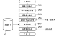
- the vehicle 5 repeatedly executes the processing flow shown in FIG. 5 while traveling to estimate the position of the own vehicle. While the vehicle 5 is traveling, the sensor array 2 executes a magnetic measurement process to acquire a one-dimensional magnetic distribution and inputs it to the control unit 32 (S101). The control unit 32 estimates the motion of the vehicle 5 based on the measured vehicle speed and the measured steering angle (S103, motion estimation process), and estimates the positional displacement of the one-dimensional region on the road surface facing the sensor array 2.
- the control unit 32 stacks the one-dimensional magnetic distributions acquired by the sensor array 2 according to the positional displacement of the one-dimensional region on the road surface facing the sensor array 2 to generate a two-dimensional measured magnetic distribution (S105, Magnetic distribution generation processing). Further, the control unit 32 converts the road surface magnetic distribution M2 associated with the structural map M1 (see FIG. 1) into a converted magnetic distribution which is a magnetic distribution of the mounting height of the magnetic sensor Cn (S107, conversion process). ). Then, the control unit 32 estimates the position of the own vehicle by specifying the corresponding region of the measured magnetic distribution in the road surface magnetic distribution M2 (S109, position estimation process).
- the magnetic measurement process is a process executed by the sensor array 2.
- the sensor array 2 executes a magnetic measurement process by 15 magnetic sensors Cn at a frequency of 3 kHz.
- the sensor array 2 acquires 15 magnetic measurement values by the magnetic sensor Cn at a frequency of 3 kHz, and inputs magnetic data, which are the 15 magnetic measurement values, to the control unit 32 at the same frequency.
- the magnetic data which is the 15 magnetic measurement values input to the control unit 32 by the sensor array 2 is a one-dimensional discrete value distribution along the vehicle width direction.
- the width of the one-dimensional magnetic distribution which is the distribution of the one-dimensional discrete values, is 1.5 m, which is equal to the range in which the magnetic sensor Cn is arranged in the sensor array 2.
- the sensor array 2 links the identification information to the one-dimensional magnetic distribution and inputs it to the control unit 32.
- the identification information associated with the one-dimensional magnetic distribution can be used to identify the one-dimensional magnetic distribution that constitutes the measured magnetic distribution.
- the motion estimation process is a process executed by the control unit 32 (motion estimation unit 321) to estimate the motion of the vehicle 5.
- the control unit 32 estimates the motion of the vehicle 5 by using the vehicle speed measured by the vehicle speed sensor 355 and the steering angle measured by the steering steering angle sensor 353. As will be described later, the control unit 32 of this example estimates the motion of the vehicle 5 by decomposing it into a component of translational motion and a component of rotational motion.
- the control unit 32 estimates the movement of the vehicle 5 during the interval period (1/3000 seconds) of the magnetic measurement process executed at a frequency of 3 kHz using the measured vehicle speed and the measured steering angle.
- the motion of the vehicle 5 is a motion of moving forward at the measured vehicle speed for 1/3000 seconds along the steering direction specified by the measured steering angle.
- the center of the sensor array 2 (the position of the magnetic sensor C8) is set as a representative point of the vehicle 5, and the motion of the center of the sensor array 2 is estimated.
- the movement of the center of the sensor array 2 is, for example, the movement Mo of the arc-shaped arrow in FIG.
- This motion Mo can be decomposed into a vector V in the figure representing a component of translational motion and a turning angle R representing a component of rotational motion.
- the motion Mo of the vehicle 5 is estimated by decomposing it into the vector V and the turning angle R. If the vector V and the turning angle R are determined with reference to the position of a certain vehicle, the position and orientation of the vehicle after displacement are uniquely determined.
- the center of the sensor array 2 is set as a representative point of the vehicle 5. Therefore, the positional displacement of the one-dimensional region on the road surface 100S facing the sensor array 2 and the one-dimensional magnetic distribution, which is the magnetic distribution of this one-dimensional region, coincides with the motion Mo of the vehicle 5.
- the one-dimensional region on the road surface 100S facing the sensor array 2 and the positional displacement of the one-dimensional magnetic distribution can be specified by the vector V estimated by the above motion estimation process and the turning angle R.
- the magnetic distribution generation processing is executed by the control unit 32 (magnetic distribution generation unit 323) in order to generate the measured magnetic distribution which is the magnetic distribution on the road surface 100S measured by using the sensor array 2. It is a process.
- the control unit 32 takes in the above-mentioned one-dimensional magnetic distribution composed of magnetic data which are 15 magnetic measurement values by the sensor array 2 at a frequency of 3 kHz, and generates a two-dimensional measurement magnetic distribution.
- the measured magnetic distribution is acquired by the sensor array 2 of the vehicle 5 scanning the road surface 100S like a "line scanner".
- the region of this measurement magnetic distribution is the region scanned by the sensor array 2.
- the control unit 32 erases the one-dimensional magnetic distribution having the oldest acquisition time among the measured magnetic distributions. According to such a procedure, the magnetic distribution of the 1.5 m wide two-dimensional region extending along the traveling locus of the vehicle 5 from the one-dimensional region on the road surface 100S facing the sensor array 2 is measured. Can be generated as.
- the number of times the one-dimensional magnetic distribution is incorporated is variable according to the vehicle speed so that the dimension of the measured magnetic distribution in the longitudinal direction (corresponding to the traveling direction of the vehicle) is a predetermined distance.
- the dimension of the measured magnetic distribution in the longitudinal direction is preferably, for example, about 2 m to 10 m.
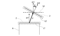
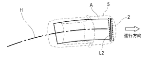
- the positional relationship between the existing measured magnetic distribution A when incorporating the new one-dimensional magnetic distribution into the measured magnetic distribution and the newly incorporated one-dimensional magnetic distribution L2 will be described with reference to FIGS. 7 and 8.
- the positional relationship between the newest one-dimensional magnetic distribution L1 in the existing measured magnetic distribution A and the newly incorporated one-dimensional magnetic distribution L2 can be expressed by the vector V estimated by the motion estimation process and the turning angle R. ..
- FIG. 7 shows the positional relationship between the one-dimensional magnetic distributions L1 and L2 when the vehicle 5 goes straight, for example.
- the position of the one-dimensional magnetic distribution L2 newly incorporated into the measurement magnetic distribution A is determined by the vector V orthogonal to the longitudinal direction of the one-dimensional magnetic distribution L1.
- FIG. 8 shows, for example, the positional relationship between L1 and L2 when the vehicle 5 travels on a curve.
- the position and orientation (posture) of the one-dimensional magnetic distribution L2 are determined by rotating the one-dimensional range Lp determined by the vector V oblique to the one-dimensional magnetic distribution L1 by the amount of the turning angle R. ..
- dir1 indicates a direction orthogonal to the one-dimensional magnetic distribution L1 and the one-dimensional range Lp
- dir2 indicates a direction orthogonal to the one-dimensional magnetic distribution L2.
- the turning angle R is the angle formed by dir1 and dir2.
- a rectangular measured magnetic distribution A extending along the traveling locus H of the vehicle 5 with the one-dimensional magnetic distribution L2 in the region facing the sensor array 2 as an end. Is formed.
- the measured magnetic distribution extending in a curve along the traveling locus H of the vehicle 5 with the one-dimensional magnetic distribution L2 in the region facing the sensor array 2 as the end. A is formed.
- the conversion process is a process of converting the road surface magnetic distribution M2 (the magnetic distribution of the road surface) constituting the map 1 (see FIG. 1) into a mode that can be easily collated with the measured magnetic distribution A.
- the control unit 32 executes a simulation for estimating the distribution of the magnetic charge acting on each point at a predetermined height from the road surface. By executing this simulation, the control unit 32 converts the road surface magnetic distribution M2 into a converted magnetic distribution M2D (see FIG. 11), which is a magnetic distribution of the mounting height of the magnetic sensor Cn.
- the position estimation process is a process executed by the control unit 32 (position estimation unit 327) to estimate the position of the own vehicle on the map.
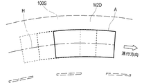
- the control unit 32 identifies a region of the road surface magnetic distribution M2 corresponding to the measured magnetic distribution A by collating the converted magnetic distribution M2D based on the road surface magnetic distribution M2 with the measured magnetic distribution A (FIG. 11). Specifically, the control unit 32 executes a correlation calculation between the converted magnetic distribution M2D and the measured magnetic distribution A, and identifies a region of the converted magnetic distribution M2D that has a high degree of coincidence with the measured magnetic distribution A. If the correlation calculation between the converted magnetic distribution M2D and the measured magnetic distribution A is performed over the entire road surface 100S, the amount of calculation may become enormous. If the positioning position by the GPS unit 351 is referred to and the measurement magnetic distribution A is collated by limiting the measurement magnetic distribution A to a range close to the positioning position as a reference, the amount of calculation required for the above correlation calculation can be suppressed.
- the position estimation process is a process of calculating the mutual correlation coefficient normalized by the correlation calculation of Equation 1.
- Equation 1 shows the degree of agreement between the converted magnetic distribution M2D and the measured magnetic distribution A when the measured magnetic distribution A is superimposed on the region represented by the specific coordinates (u, v) in the converted magnetic distribution M2D. It is an expression for calculating the mutual correlation coefficient representing.
- Equation 1 is an arithmetic expression of the normalized intercorrelation coefficient, and the maximum intercorrelation coefficient 1 is obtained when the converted magnetic distribution M2D and the measured magnetic distribution A match.
- f represents the converted magnetic distribution M2D
- t represents the measured magnetic distribution A.
- the regional size of the measured magnetic distribution A is Nx ⁇ Ny, and the regional size of the converted magnetic distribution M2D is sufficiently larger than the measured magnetic distribution A.
- Equation 1 changing (u, v) means changing the region that overlaps with the measured magnetic distribution A in the transformed magnetic distribution M2D.
- Calculating the intercorrelation coefficient for various coordinates (u, v) is equivalent to checking the degree of agreement while shifting the position of the measured magnetic distribution A with respect to the converted magnetic distribution M2D, for example, as shown in FIG. There is.
- the region corresponding to the coordinates (u0, v0) when the intercorrelation coefficient closest to 1, which is the maximum correlation value is obtained. It can be specified as a corresponding region of the measured magnetic distribution A.
- the vehicle position in the road surface magnetic distribution M2 can be estimated.
- the road surface magnetic distribution M2 is associated with the structural map M1 (see FIG. 1) by position data representing an absolute position. Estimating the position of the own vehicle in the road surface magnetic distribution M2 is synonymous with estimating the position of the own vehicle on the map.
- the position estimation system 1S of this example is a system that estimates the position of the own vehicle on the map by using the road surface magnetic distribution M2 which is the magnetic distribution of each point of the road surface 100S. If the position of the own vehicle on the map can be estimated, various types of driving support control including lane tracking control and automatic driving can be realized.
- the magnitude of the magnetic amount varies depending on the magnetic material mixed in the pavement material forming the road surface 100S and the magnetic source such as a metal manhole or a bridge joint installed on the road surface 100S. It is formed. Since these magnetic sources are fixed in position on the road surface 100S, there is little positional variation.
- the road surface magnetic distribution M2 derived from a magnetic source that is fixed in position the position of the own vehicle on the map can be estimated with high accuracy.
- the use of the positioning position by the GPS unit 351 is effective.
- the range for collating the measured magnetic distribution A in the road surface magnetic distribution M2 can be limited, and the amount of calculation required for the correlation calculation between the converted magnetic distribution M2D and the measured magnetic distribution A can be suppressed.
- the collation range of the measured magnetic distribution A can be limited in the road surface magnetic distribution M2 (conversion magnetic distribution M2D), and the efficiency of the correlation calculation can be improved.
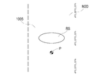
- the range RS that is a candidate for the own vehicle position is determined based on the estimated own vehicle position P. It is good to set. Since this range RS is a candidate for the region where the sensor array 2 after displacement faces, it is sufficient to collate the one-dimensional magnetic distribution by the magnetic measurement process within this range RS. In this way, after estimating the position of the own vehicle, the position of the own vehicle can be estimated by collating the one-dimensional magnetic distribution within the range RS of FIG.
- the one-dimensional magnetic distribution correlation calculation is more efficient than the two-dimensional magnetic distribution correlation calculation because the amount of calculation is smaller.
- the measured magnetic distribution A or one-dimensional magnetic distribution in the road surface magnetic distribution M2 The position and posture of can be specified. For example, after the position of the own vehicle can be estimated, the estimated position of the own vehicle is used as a reference by specifying the position and orientation of the measured magnetic distribution A and the one-dimensional magnetic distribution in the road surface magnetic distribution M2. It is possible to grasp changes in relative position and orientation (vehicle orientation, posture). As described above, the configuration for estimating the position of the vehicle 5 by collating the road surface magnetic distribution M2 (converted magnetic distribution M2D) with the measured magnetic distribution A or the one-dimensional magnetic distribution can replace the IMU.
- a configuration in which the positioning position by the GPS unit 351 is used in order to suppress the calculation amount of the position estimation process and efficiently execute the position estimation process is illustrated.
- a communication unit such as a radio wave beacon or an infrared beacon installed on the roadside or the like. If the vehicle 5 is equipped with a receiving unit, the position of the own vehicle can be roughly grasped according to the reception of the beacon radio wave. Furthermore, it is also good to recognize the name of the intersection, the place name, etc. and roughly grasp the position of the own vehicle by processing the image captured by the front camera.
- the position of the own vehicle may be roughly grasped by collating with the foreground image stored in the in-vehicle database or the database accessible via the Internet or the like. If the position of the own vehicle can be roughly grasped, the amount of calculation required for the correlation calculation in the position estimation process can be suppressed.
- an automatic driving system is illustrated as a system to be combined with the position estimation system 1S. Instead of the automatic driving system, apply a deviation warning system that warns of deviation from the lane and a lane keeping system that automatically steers the steering wheel along the lane and generates steering assist force to avoid deviation from the lane. That is also good.
- the server device may have the function of the map DB 40.
- the vehicle 5 may transmit information necessary for estimating the position of the own vehicle to the server device.
- the server device may have a function of executing magnetic distribution generation processing and position estimation processing.
- the one-dimensional magnetic distribution may be transmitted from the vehicle 5 to the server device each time the magnetic measurement process is executed.
- the server device can estimate the own vehicle position of the source vehicle by using the one-dimensional magnetic distribution received from the vehicle and reply.
- the magnetic distribution is converted into the magnetic distribution of the mounting height of the magnetic sensor Cn (conversion magnetic distribution), and the collation with the measured magnetic distribution is performed.
- conversion magnetic distribution it is also possible to convert the measured magnetic distribution into the magnetic distribution of the road surface 100S and perform collation with the road surface magnetic distribution M2.
- the measured magnetic distribution may be directly collated without converting the road surface magnetic distribution M2.
- the mounting height of the magnetic sensor Cn is measured using the height sensor 357 in order to convert it into the magnetic distribution of the mounting height of the magnetic sensor Cn based on the road surface magnetic distribution M2. Then, the road surface magnetic distribution M2 is converted into the magnetic distribution of the mounting height of the magnetic sensor Cn by the simulation in consideration of the mounting height, and the converted magnetic distribution is acquired.
- a storage unit that stores the mounting height of the magnetic sensor Cn as a set value may be provided.
- the ratio (attenuation factor, etc.) of the magnetic measurement values by the two magnetic sensors arranged along the vertical direction can be specified. Then, by executing a simulation calculation including the ratio of the magnetic measurement values of the two magnetic sensors whose height differences are known as variables, the road surface magnetic distribution M2 is converted into the magnetic distribution of the mounting height of the magnetic sensor Cn. it can.
- a magnetic marker having a known magnetic charge may be installed on the road surface 100S.
- the road surface may be paved using a pavement material mixed with a magnetic material such as iron oxide magnetic powder.
- a magnetic material such as iron oxide magnetic powder.
- the magnetic material in the pavement material is magnetized, and the undulations of the road surface magnetic distribution M2 tend to increase. If the undulations of the magnetic distribution are expanded, the magnetic distribution can be easily collated and the accuracy can be improved. It is also possible to non-uniformly magnetize the road surface paved with a pavement material mixed with a magnetic material. In this case, the undulations of the magnetic distribution can be further expanded, and the magnetic distribution can be easily collated. It is also possible to prepare a pavement material in which a magnetic material is mixed and a normal pavement material that does not contain a magnetic material. In this case, it is also possible to non-uniformly supply the two types of pavement materials to the road surface without mixing them. Since the composition ratio of the magnetic material differs depending on the position of the road surface, the undulations of the magnetic distribution can be expanded.
- a predetermined pattern such as a checkered pattern in which a rectangular area with strong magnetism and a rectangular area with weak magnetism appear alternately. If the pattern formed by the strength of the magnetism is used, the matching between the magnetic distributions becomes easy, and the accuracy of the position estimation can be improved.
- the road surface is magnetized so as to form a predetermined pattern, for example, by using a dividing line between a rectangular area having a large magnetic charge and a rectangular area having a small magnetic charge, matching of the measured magnetic distribution is efficient. Can be done well.
- the collation may be executed on the premise that it matches the dividing line in the road surface magnetic distribution M2.
- the predetermined pattern may be a pattern in which information can be read, such as a one-dimensional or two-dimensional barcode.
- the measurement magnetic distribution which is a two-dimensional magnetic distribution obtained by accumulating the one-dimensional magnetic distributions by the magnetic measurement process, is collated. It is also possible to collate the temporal distribution of the magnetic measurement values by any one of the magnetic sensors Cn, that is, the one-dimensional distribution along the traveling locus of the vehicle. It is also possible to adopt a sensor array in which magnetic sensors are arranged two-dimensionally. In this case, the two-dimensional magnetic distribution measured by this sensor array can be collated. Alternatively, a plurality of sensor arrays having the same specifications as those of the sensor array 2 may be prepared and arranged at a plurality of locations in the traveling direction of the vehicle.
- the plurality of sensor arrays may be mounted so as to be parallel to each other, or may be mounted so as to intersect each other in an L-shape or a cross shape.
- the road surface magnetic distribution may be the distribution of the magnetic gradient, which is an example of magnetic data based on the magnetic charge at each point on the road surface.
- the magnetic gradient can be obtained, for example, as the difference between the magnetic charges of adjacent points.
- the measured magnetic distribution to be collated with the road surface magnetic distribution of the magnetic gradient should be the distribution of the magnetic gradient based on the magnetic measurement value.
- the magnetic gradient can be obtained, for example, as the difference between the magnetic measurement values of the adjacent magnetic sensors among the magnetic sensors Cn constituting the sensor array 2.
- the magnetic gradient suppresses magnetic components that act uniformly or nearly uniformly on the magnetic sensor. Therefore, in the magnetic gradient, the magnetic component acting from the magnetic source existing relatively far away is suppressed, and the magnetic component acting from the magnetic source such as the road surface existing relatively close is relatively emphasized. .. Therefore, when estimating the position by using the magnetic pattern of the road surface facing the magnetic sensor, it is preferable to use the distribution of the magnetic gradient. By using the distribution of the magnetic gradient, it is possible to suppress the influence of surrounding vehicles, guardrails, signboards and other magnetic sources, and the influence of geomagnetism, and improve the accuracy of position estimation.
- the difference between the magnetic measurement values at different acquisition points into the difference per distance specified based on the vehicle speed information separately given. It is also possible to obtain the difference per distance for each of the two magnetic sensors, and further obtain the difference between the two magnetic sensors to obtain the magnetic gradient. In this case, the effect that the above magnetic gradient can be obtained without giving the interval of the magnetic markers arranged on the road in advance can be expected. Further, for example, in obtaining the magnetic gradient due to the difference between the magnetic measurement values at different time points by one magnetic sensor, it is also possible to obtain the magnetic gradient due to the difference per distance specified by the vehicle speed information separately given. In this case, it is less necessary to install two in-vehicle sensor units in the front and rear. If the magnetic gradient can be obtained from one sensor unit, the design burden for securing the mounting position of the sensor unit can be reduced, and at the same time, the mounting cost of the sensor unit can be expected to be reduced.
- Example 2 This example is an application example of the position estimation system 1S to the road 100 on which the magnetic marker 10 is laid. This content will be described with reference to FIGS. 3, 13 to 18. As shown in FIG. 13, magnetic markers 10 are laid on the illustrated road 100, for example, every 10 m.
- the sensor array 2 executes the magnetic measurement process (S101), and the control unit 32 executes the motion estimation process (S103), the magnetic distribution generation process (S105), and the position, as in the first embodiment.
- the estimation process (S109) is executed (FIG. 14).
- the main difference from the first embodiment is that the sensor array 2 executes a marker detection process (S102) in addition to the magnetic measurement process (S101).
- the sensor array 2 executes the marker detection process at a frequency of 3 kHz using the magnetic sensor Cn.
- the magnetic sensor Cn is configured to measure the magnetic components in the traveling direction and the vehicle width direction of the vehicle. For example, when the magnetic sensor Cn moves in the traveling direction and passes directly above the magnetic marker 10, the magnetic measurement values in the traveling direction are positive and negative inverted before and after the magnetic marker 10 as shown in FIG. It changes so as to intersect zero at a position directly above 10. Therefore, while the vehicle is traveling, it can be determined that the sensor array 2 is located directly above the magnetic marker 10 when a zero cross Zc in which the positive and negative directions of the magnetism in the traveling direction detected by any of the magnetic sensors Cn occurs. ..
- the detection processing circuit 212 determines that the magnetic marker 10 has been detected when the sensor array 2 is located directly above the magnetic marker 10 and a zero cross Zc of the magnetic measurement values in the traveling direction occurs.
- a magnetic sensor having the same specifications as the magnetic sensor Cn moves along a virtual line in the vehicle width direction passing directly above the magnetic marker 10.
- the magnetic measurement value in the vehicle width direction is reversed in positive and negative directions on both sides of the magnetic marker 10, and changes so as to intersect zero at a position directly above the magnetic marker 10.
- the positive and negative of the magnetism in the vehicle width direction detected by the magnetic sensor Cn differs depending on which side is located via the magnetic marker 10.
- the two magnetic sensors Cn adjacent to each other with the zero cross Zc in which the positive and negative of the magnetism in the vehicle width direction are reversed The position in the vehicle width direction of the magnetic marker 10 is the intermediate position or the position immediately below the magnetic sensor Cn in which the magnetism in the vehicle width direction to be detected is zero and the positive and negative of the magnetic sensor Cn on both outer sides are reversed. .. This position in the vehicle width direction indicates the relative position of the vehicle 5 with respect to the magnetic marker 10.
- the sensor array 2 inputs marker detection information including information such as the detection and the position in the vehicle width direction to the control unit (reference numeral 32 in FIG. 3).
- the position in the vehicle width direction is represented as a position in the one-dimensional direction in the one-dimensional magnetic distribution acquired by the magnetic measurement process.
- the sensor array 2 associates the marker detection information with the identification information of the one-dimensional magnetic distribution when the magnetic marker 10 is detected.
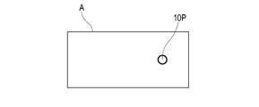
- the control unit that executes the magnetic distribution generation process plots the position of the magnetic marker 10 as the marker placement point 10P in the measurement magnetic distribution A (FIG. 17).
- the measured magnetic distribution A in which the one-dimensional magnetic distribution is two-dimensionally accumulated along the traveling locus of the vehicle which one-dimensional magnetic distribution the marker placement point 10P is on is linked to the marker detection information. It can be identified by the identification information of the one-dimensional magnetic distribution obtained. Further, the position of the marker arrangement point 10P in the measurement magnetic distribution A in the vehicle width direction can be specified by the position in the vehicle width direction included in the marker detection information.
- the position of the magnetic marker 10 is plotted as the marker placement point 10P as in the above measurement magnetic distribution A.
- the road surface magnetic distribution M2 can be acquired by a measuring vehicle capable of executing the above marker detection process, in addition to the functions of the measuring vehicle exemplified in the first embodiment.
- the converted magnetic distribution M2D which is a magnetic distribution obtained by converting the road surface magnetic distribution M2
- the marker placement points 10P are plotted at the same positions as the marker placement points in the road surface magnetic distribution M2.
- the control unit that executes the position estimation process collates the measured magnetic distribution A illustrated in FIG. 17 with the converted magnetic distribution M2D on which the marker placement points 10P are plotted.
- the measurement magnetic distribution A includes a plot of marker placement points 10P representing the positions of the magnetic markers 10.
- the correlation calculation may be performed only at the positions where the marker placement points P coincide with each other. That is, the position of the measured magnetic distribution A may be shifted in increments of 10 m with respect to the converted magnetic distribution M2D, and the amount of calculation for the correlation calculation can be significantly suppressed.
- the region corresponding to the measured magnetic distribution A from the regions where the marker placement points 10P (positions of the magnetic markers 10) coincide with each other in the road surface magnetic distribution M2 or the converted magnetic distribution M2D. ..
- the marker placement point 10P can be used as a magnetic singularity in the magnetic distribution.
- Example 3 This example is an example based on the position estimation system of the first embodiment, and is an application example to a road in which a magnetic marker 10 is laid in a state where an absolute position can be specified. This content will be described with reference to FIGS. 19 to 21.
- a magnetic marker 10 having an RF-ID tag 15 attached to the surface is laid on the road surface (FIG. 19).
- the vehicle 5 is provided with a tag reader 34 capable of communicating with the RF-ID tag 15 (FIG. 20).
- the RF-ID tag 15 transmits position information indicating the absolute position of the corresponding magnetic marker 10.
- the detection processing circuit 20 of the sensor array 2 can execute the marker detection processing illustrated in the second embodiment. As described above, according to the marker detection process, the magnetic marker 10 can be detected and the position of the vehicle 5 in the vehicle width direction with respect to the magnetic marker 10 can be measured.
- the control unit 32 acquires the absolute position of the magnetic marker 10 by receiving the position information from the RF-ID tag 15 attached to the detected magnetic marker 10. Then, the position deviated from the absolute position of the magnetic marker 10 by the position of the magnetic marker 10 in the vehicle width direction measured by the marker detection process is specified as the own vehicle position (position at the center of the sensor array 2).
- the control unit 32 identifies a region corresponding to the measured magnetic distribution by referring to the map including the road surface magnetic distribution M2, as in the configuration described in the first embodiment. Estimate the vehicle position. At this time, according to the steering angle measured by the steering angle sensor 353 and the vehicle speed measured by the vehicle speed sensor 355, the motion Mo of the vehicle 5 can be estimated as in the first embodiment (FIG. 21). By estimating the motion Mo of the vehicle 5, it is possible to estimate the arrival position of the vehicle 5 according to the elapsed time after passing through the magnetic marker 10.
Landscapes
- Engineering & Computer Science (AREA)
- Remote Sensing (AREA)
- Radar, Positioning & Navigation (AREA)
- Physics & Mathematics (AREA)
- General Physics & Mathematics (AREA)
- Automation & Control Theory (AREA)
- Life Sciences & Earth Sciences (AREA)
- General Life Sciences & Earth Sciences (AREA)
- Environmental & Geological Engineering (AREA)
- Geology (AREA)
- Electromagnetism (AREA)
- Aviation & Aerospace Engineering (AREA)
- Geophysics (AREA)
- Navigation (AREA)
- Traffic Control Systems (AREA)
- Instructional Devices (AREA)
Abstract
Description
前記磁気センサによる磁気計測値を取得する磁気計測処理と、
前記磁気計測処理により取得された磁気計測値に基づく磁気データの分布を表す計測磁気分布を生成する磁気分布生成処理と、
路面の各点の磁気量に基づく磁気データの分布を表す路面磁気分布が対応付けられた地図を参照することにより、前記路面磁気分布のうち前記計測磁気分布に対応する領域を特定し、当該計測磁気分布に対応する領域の前記地図上の位置に基づいて前記自車位置を推定する位置推定処理と、を含む位置推定方法にある。
路面の各点の磁気量に基づく磁気データの分布である路面磁気分布が対応付けられた地図を記憶する記憶部と、
前記磁気センサによる磁気計測値を取得し、該磁気計測値に基づく磁気データの分布である計測磁気分布を生成する磁気分布生成部と、
前記記憶部が記憶する地図に対応付けられた路面磁気分布のうち前記計測磁気分布に対応する領域を特定し、当該計測磁気分布に対応する領域の前記地図上の位置に基づいて前記自車位置を推定する位置推定部と、を含む位置推定システムにある。
(実施例1)
本例は、地図上で自車両の位置を精度高く推定するための位置推定方法及び位置推定システム1Sに関する例である。この内容について、図1~図12を用いて説明する。
(A)磁気計測処理
磁気計測処理は、センサアレイ2が実行する処理である。センサアレイ2は、15個の磁気センサCnによる磁気計測処理を3kHzの頻度で実行する。センサアレイ2は、磁気センサCnによる15個の磁気計測値を3kHzの頻度で取得し、15個の磁気計測値である磁気データを同じ頻度で制御ユニット32に入力する。上記のごとく、センサアレイ2が制御ユニット32に入力する15個の磁気計測値である磁気データは、車幅方向に沿う1次元的な離散値の分布である。この1次元的な離散値の分布である1次元磁気分布の幅は、センサアレイ2において磁気センサCnが配置された範囲に等しい1.5mである。なお、センサアレイ2は、1次元磁気分布に対して識別情報をひも付けて、制御ユニット32に入力する。1次元磁気分布にひも付けられた識別情報は、計測磁気分布を構成する1次元磁気分布を識別するために利用可能である。
運動推定処理は、車両5の運動を推定するために制御ユニット32(運動推定部321)が実行する処理である。制御ユニット32は、車速センサ355による計測車速、ステアリング舵角センサ353による計測操舵角を利用し、車両5の運動を推定する。後述する通り、本例の制御ユニット32は、並進運動の成分と、回転運動の成分と、に分解することで、車両5の運動を推定する。
磁気分布生成処理は、センサアレイ2を用いて計測した路面100S上の磁気分布である計測磁気分布を生成するために制御ユニット32(磁気分布生成部323)が実行する処理である。制御ユニット32は、センサアレイ2による15個の磁気計測値である磁気データで構成される上記の1次元磁気分布を3kHzの頻度で取り込み、2次元的な計測磁気分布を生成する。
変換処理は、地図1(図1参照。)を構成する路面磁気分布M2(路面の磁気分布)を、計測磁気分布Aと照合し易い態様に変換する処理である。制御ユニット32は、路面から所定高さの各点に作用する磁気量の分布を推定するシミュレーションを実行する。制御ユニット32は、このシミュレーションを実行することで路面磁気分布M2を、磁気センサCnの取付け高さの磁気分布である変換磁気分布M2D(図11参照。)に変換する。
位置推定処理は、地図上で自車位置を推定するために制御ユニット32(位置推定部327)が実行する処理である。制御ユニット32は、路面磁気分布M2に基づく変換磁気分布M2Dと計測磁気分布Aとを照合することで(図11)、路面磁気分布M2のうち計測磁気分布Aに対応する領域を特定する。具体的には、制御ユニット32は、変換磁気分布M2Dと計測磁気分布Aとの相関演算を実行し、変換磁気分布M2Dのうち計測磁気分布Aと一致度が高い領域を特定する。なお、路面100Sの全域で、変換磁気分布M2Dと計測磁気分布Aとの相関演算を実施しようとすると演算量が膨大になる可能性がある。GPSユニット351による測位位置を参照し、その測位位置を基準とする近傍の範囲に限定して計測磁気分布Aの照合を実行すれば、上記の相関演算に要する演算量を抑制できる。

本例は、磁気マーカ10が敷設された道路100に対する位置推定システム1Sの適用例である。この内容について、図3、図13~図18を参照して説明する。
例示する道路100には、図13のごとく、例えば10m毎に磁気マーカ10が敷設されている。この道路100を車両が走行する際、実施例1と同様、センサアレイ2によって磁気計測処理(S101)が実行され、制御ユニット32によって運動推定処理(S103)、磁気分布生成処理(S105)、位置推定処理(S109)が実行される(図14)。実施例1との主たる相違点は、センサアレイ2が磁気計測処理(S101)に加えて、マーカ検出処理(S102)を実行する点にある。センサアレイ2は、磁気センサCnを用いて3kHzの頻度でマーカ検出処理を実行する。
なお、その他の構成及び作用効果は実施例1と同様である。
本例は、実施例1の位置推定システムに基づく例であって、絶対位置を特定可能な状態で磁気マーカ10が敷設された道路への適用例である。この内容について、図19~図21を参照して説明する。
本例では、RF-IDタグ15が表面に貼り付けられた磁気マーカ10が路面に敷設されている(図19)。車両5には、実施例1の構成に加えて、RF-IDタグ15と通信可能なタグリーダ34が設けられている(図20)。RF-IDタグ15は、対応する磁気マーカ10の絶対位置を表す位置情報を送信する。
なお、その他の構成及び作用効果については実施例1と同様である。
1 地図
10 磁気マーカ
2 センサアレイ
32 制御ユニット
321 運動推定部
323 磁気分布生成部
325 変換処理部
327 位置推定部
351 GPSユニット
353 ステアリング舵角センサ
355 車速センサ
357 高さセンサ
40 地図データベース(記憶部)
5 車両
A 計測磁気分布
Cn 磁気センサ
M1 構造地図
M2 路面磁気分布
M2D 変換磁気分布
Claims (14)
- 走路の表面をなす路面から作用する磁気を計測する磁気センサを備える車両が自車位置を推定するための位置推定方法であって、
前記磁気センサによる磁気計測値を取得する磁気計測処理と、
前記磁気計測処理により取得された磁気計測値に基づく磁気データの分布を表す計測磁気分布を生成する磁気分布生成処理と、
路面の各点の磁気量に基づく磁気データの分布を表す路面磁気分布が対応付けられた地図を参照することにより、前記路面磁気分布のうち前記計測磁気分布に対応する領域を特定し、当該計測磁気分布に対応する領域の前記地図上の位置に基づいて前記自車位置を推定する位置推定処理と、を含む位置推定方法。 - 請求項1において、前記磁気計測値に基づく磁気データ、及び前記路面の各点の磁気量に基づく磁気データは、磁気勾配であって、前記計測磁気分布及び前記路面磁気分布は、磁気勾配の分布である位置推定方法。
- 請求項1または2において、前記路面磁気分布を、前記磁気センサの取付高さの分布に変換する変換処理を含み、
前記位置推定処理において、前記変換処理による変換後の分布と前記計測磁気分布とを照合して、前記計測磁気分布に対応する領域を特定する位置推定方法。 - 請求項1または2において、前記計測磁気分布を、路面の高さの分布に変換する変換処理を含み、
前記位置推定処理において、前記変換処理による変換後の分布と前記路面磁気分布とを照合して、前記計測磁気分布に対応する領域を特定する位置推定方法。 - 請求項3または4において、前記変換処理は、取付高さが異なる2つの磁気センサによる磁気計測値の比率に応じて分布を変換する処理である位置推定方法。
- 請求項3~5のいずれか1項において、前記変換処理は、路面に敷設された磁気的な強度が既知の磁気発生源である磁気マーカについて前記磁気センサが取得した磁気計測値の大きさに応じて分布を変換する処理である位置推定方法。
- 請求項1~6のいずれか1項において、前記走路には、絶対位置を特定可能な状態で磁気発生源としての磁気マーカが間隔を空けて敷設されており、
前記位置推定処理において、前記磁気マーカが車両によって検知された場合に、当該磁気マーカの絶対位置を基準として自車位置を推定する一方、
前記磁気マーカが非検知の場合には、前記計測磁気分布に対応する領域の前記地図上の位置に基づいて前記自車位置を推定する位置推定方法。 - 請求項7において、前記磁気マーカが非検知の場合、いずれかの磁気マーカを検知した後の車両の到達位置を推定すると共に当該到達位置が属する前記地図上の範囲を選択し、当該地図上の範囲の中で前記計測磁気分布に対応する領域を特定する位置推定方法。
- 請求項1~8のいずれか1項において、前記路面磁気分布及び前記計測磁気分布では、路面に敷設された磁気マーカの位置が特定されており、
前記位置推定処理では、前記路面磁気分布のうち前記磁気マーカの位置が一致している領域の中から前記計測磁気分布に対応する領域を特定する位置推定方法。 - 走路の表面をなす路面側から作用する磁気を計測する磁気センサを備える車両が自車位置を推定する位置推定システムであって、
路面の各点の磁気量に基づく磁気データの分布である路面磁気分布が対応付けられた地図を記憶する記憶部と、
前記磁気センサによる磁気計測値を取得し、該磁気計測値に基づく磁気データの分布である計測磁気分布を生成する磁気分布生成部と、
前記記憶部が記憶する地図に対応付けられた路面磁気分布のうち前記計測磁気分布に対応する領域を特定し、当該計測磁気分布に対応する領域の前記地図上の位置に基づいて前記自車位置を推定する位置推定部と、を含む位置推定システム。 - 請求項10において、前記路面は、磁性材料の粉末である磁粉が分散する舗装材料よりなる舗装の表面であり、該舗装の中に分散している前記磁粉は、前記路面の磁気分布が所定パターンをなすように磁化されている位置推定システム。
- 請求項10または11において、前記走路に沿って磁気マーカが敷設されている位置推定システム。
- 請求項12において、前記路面磁気分布及び前記計測磁気分布では、前記磁気マーカの位置が特定され、
前記位置推定部は、前記路面磁気分布のうち前記磁気マーカの位置が一致している領域の中から前記計測磁気分布に対応する領域を特定するように構成されている位置推定システム。 - 請求項10~13のいずれか1項において、前記磁気計測値に基づく磁気データ、及び前記路面の各点の磁気量に基づく磁気データは、磁気勾配であって、記計測磁気分布及び前記路面磁気分布は、磁気勾配の分布である位置推定システム。
Priority Applications (4)
| Application Number | Priority Date | Filing Date | Title |
|---|---|---|---|
| JP2021558476A JP7360059B2 (ja) | 2019-11-22 | 2020-11-20 | 位置推定方法及び位置推定システム |
| EP20889060.8A EP4064251A4 (en) | 2019-11-22 | 2020-11-20 | Location estimation method and location estimation system |
| CN202080079217.XA CN114730524B (zh) | 2019-11-22 | 2020-11-20 | 位置推定方法以及位置推定系统 |
| US17/777,642 US12236781B2 (en) | 2019-11-22 | 2020-11-20 | Position estimation method and position estimation system |
Applications Claiming Priority (2)
| Application Number | Priority Date | Filing Date | Title |
|---|---|---|---|
| JP2019211864 | 2019-11-22 | ||
| JP2019-211864 | 2019-11-22 |
Publications (1)
| Publication Number | Publication Date |
|---|---|
| WO2021100865A1 true WO2021100865A1 (ja) | 2021-05-27 |
Family
ID=75980140
Family Applications (1)
| Application Number | Title | Priority Date | Filing Date |
|---|---|---|---|
| PCT/JP2020/043476 Ceased WO2021100865A1 (ja) | 2019-11-22 | 2020-11-20 | 位置推定方法及び位置推定システム |
Country Status (5)
| Country | Link |
|---|---|
| US (1) | US12236781B2 (ja) |
| EP (1) | EP4064251A4 (ja) |
| JP (1) | JP7360059B2 (ja) |
| CN (1) | CN114730524B (ja) |
| WO (1) | WO2021100865A1 (ja) |
Cited By (1)
| Publication number | Priority date | Publication date | Assignee | Title |
|---|---|---|---|---|
| US11294090B2 (en) * | 2017-03-28 | 2022-04-05 | Aichi Steel Corporation | Marker detection system and marker detection method |
Families Citing this family (1)
| Publication number | Priority date | Publication date | Assignee | Title |
|---|---|---|---|---|
| US12479469B2 (en) * | 2023-11-22 | 2025-11-25 | Automotive Research & Testing Center | Deciding system for moving vehicle on virtual rail and method thereof |
Citations (4)
| Publication number | Priority date | Publication date | Assignee | Title |
|---|---|---|---|---|
| JP2013186718A (ja) | 2012-03-08 | 2013-09-19 | Nissan Motor Co Ltd | 移動物体位置姿勢推定装置及び方法 |
| JP2014034251A (ja) | 2012-08-08 | 2014-02-24 | Nissan Motor Co Ltd | 車両走行制御装置及びその方法 |
| JP2018036797A (ja) * | 2016-08-30 | 2018-03-08 | 愛知製鋼株式会社 | 車両用システム及び進路推定方法 |
| WO2018056391A1 (ja) * | 2016-09-23 | 2018-03-29 | 日本電気株式会社 | 測位用地磁気マップの作成方法、位置測定方法、ノイズ測定方法及び測位用地磁気マップの作成システム |
Family Cites Families (15)
| Publication number | Priority date | Publication date | Assignee | Title |
|---|---|---|---|---|
| JP3504449B2 (ja) * | 1996-11-22 | 2004-03-08 | 本田技研工業株式会社 | 自動運転車 |
| JP5352883B2 (ja) | 2009-12-21 | 2013-11-27 | 国立大学法人宇都宮大学 | 自律移動方法及び自律移動体 |
| CN102147972A (zh) * | 2010-02-09 | 2011-08-10 | 上海秀派电子科技有限公司 | 无线地磁车辆检测装置及其安装方法 |
| JP5433525B2 (ja) * | 2010-08-06 | 2014-03-05 | 株式会社日立製作所 | 車両走行支援装置及び道路標示の作成方法 |
| KR101049515B1 (ko) * | 2011-01-26 | 2011-07-15 | 김지훈 | 시각장애인용 도로 안내 시스템 |
| KR20150125115A (ko) * | 2014-04-29 | 2015-11-09 | 한국철도기술연구원 | 자성분말이 적용된 주행경로를 생성하는 생성방법과 이를 이용한 검출장치 |
| WO2017209112A1 (ja) | 2016-06-03 | 2017-12-07 | 愛知製鋼株式会社 | 位置捕捉方法及びシステム |
| JP6928306B2 (ja) | 2017-03-28 | 2021-09-01 | 愛知製鋼株式会社 | 磁気マーカの施工方法及び作業システム |
| JP6946695B2 (ja) * | 2017-03-30 | 2021-10-06 | 愛知製鋼株式会社 | マーカシステム |
| EP3605487A4 (en) | 2017-03-28 | 2020-10-07 | Aichi Steel Corporation | MARKER SYSTEM |
| DE102017215932B3 (de) * | 2017-09-11 | 2019-02-28 | Audi Ag | Verfahren zur Ermittlung einer Positionsinformation eines Kraftfahrzeugs und Kraftfahrzeug |
| JP6965815B2 (ja) | 2018-04-12 | 2021-11-10 | 愛知製鋼株式会社 | マーカ検出システム、及びマーカ検出システムの運用方法 |
| CN108592903B (zh) * | 2018-07-17 | 2021-01-26 | 北京九天探索科技有限公司 | 一种基于路网地磁基准库的车辆地磁匹配定位方法 |
| JP6947487B2 (ja) * | 2018-09-28 | 2021-10-13 | 先進モビリティ株式会社 | 自動運転システム |
| TW202045948A (zh) * | 2019-05-31 | 2020-12-16 | 張阿粉 | 磁場定位方法及其系統 |
-
2020
- 2020-11-20 CN CN202080079217.XA patent/CN114730524B/zh active Active
- 2020-11-20 EP EP20889060.8A patent/EP4064251A4/en active Pending
- 2020-11-20 WO PCT/JP2020/043476 patent/WO2021100865A1/ja not_active Ceased
- 2020-11-20 JP JP2021558476A patent/JP7360059B2/ja active Active
- 2020-11-20 US US17/777,642 patent/US12236781B2/en active Active
Patent Citations (4)
| Publication number | Priority date | Publication date | Assignee | Title |
|---|---|---|---|---|
| JP2013186718A (ja) | 2012-03-08 | 2013-09-19 | Nissan Motor Co Ltd | 移動物体位置姿勢推定装置及び方法 |
| JP2014034251A (ja) | 2012-08-08 | 2014-02-24 | Nissan Motor Co Ltd | 車両走行制御装置及びその方法 |
| JP2018036797A (ja) * | 2016-08-30 | 2018-03-08 | 愛知製鋼株式会社 | 車両用システム及び進路推定方法 |
| WO2018056391A1 (ja) * | 2016-09-23 | 2018-03-29 | 日本電気株式会社 | 測位用地磁気マップの作成方法、位置測定方法、ノイズ測定方法及び測位用地磁気マップの作成システム |
Non-Patent Citations (1)
| Title |
|---|
| See also references of EP4064251A4 |
Cited By (1)
| Publication number | Priority date | Publication date | Assignee | Title |
|---|---|---|---|---|
| US11294090B2 (en) * | 2017-03-28 | 2022-04-05 | Aichi Steel Corporation | Marker detection system and marker detection method |
Also Published As
| Publication number | Publication date |
|---|---|
| US20230003530A1 (en) | 2023-01-05 |
| JPWO2021100865A1 (ja) | 2021-05-27 |
| US12236781B2 (en) | 2025-02-25 |
| CN114730524A (zh) | 2022-07-08 |
| CN114730524B (zh) | 2025-02-28 |
| EP4064251A4 (en) | 2023-12-13 |
| EP4064251A1 (en) | 2022-09-28 |
| JP7360059B2 (ja) | 2023-10-12 |
Similar Documents
| Publication | Publication Date | Title |
|---|---|---|
| KR102425272B1 (ko) | 디지털 지도에 대한 위치를 판별하기 위한 방법 및 시스템 | |
| Brenner | Extraction of features from mobile laser scanning data for future driver assistance systems | |
| Rose et al. | An integrated vehicle navigation system utilizing lane-detection and lateral position estimation systems in difficult environments for GPS | |
| JP6354120B2 (ja) | 道路情報送信装置、地図生成装置、道路情報収集システム | |
| JP3561473B2 (ja) | 物体位置の追跡・検知方法及びビークル | |
| JP4897542B2 (ja) | 自己位置標定装置、自己位置標定方法および自己位置標定プログラム | |
| JP5610870B2 (ja) | 無人走行車両の誘導装置及び無人走行車両の誘導方法 | |
| CN104428686B (zh) | 用于获得车辆位置的方法和车辆 | |
| CN108628324A (zh) | 基于矢量地图的无人车导航方法、装置、设备及存储介质 | |
| JP2024020294A (ja) | 地図データ記録媒体及び地図データの生成方法 | |
| CN118279468A (zh) | 车道线标注方法、电子设备及计算机存储介质 | |
| JP2018169301A (ja) | マーカシステム | |
| JP7360059B2 (ja) | 位置推定方法及び位置推定システム | |
| JP7389360B2 (ja) | 走行路診断システム | |
| JP5375249B2 (ja) | 移動経路計画装置、移動体制御装置及び移動体 | |
| JP7381939B2 (ja) | 3次元構造推定方法及び3次元構造推定システム | |
| JP7323146B2 (ja) | 情報処理方法、プログラム、及び情報処理装置 | |
| Tang et al. | Pixel-based map matching algorithm for pedestrian dead reckoning system. | |
| KR100587397B1 (ko) | Gps 수신기, 레이저 계측기 및 사진기 장착 차량을이용한 도로 주변 시설물 측량 방법 | |
| SK1272022U1 (sk) | Spôsob lokalizácie autonómneho vozidla a zapojenie vizuálneho systému na lokalizáciu autonómneho vozidla | |
| SK992022A3 (sk) | Spôsob lokalizácie autonómneho vozidla a zapojenie vizuálneho systému na lokalizáciu autonómneho vozidla | |
| Wang et al. | An Integrated LFM/LDC/RSU Positioning Method for Autonomous Vehicles | |
| Speth et al. | Dynamic position calibration by road structure detection | |
| KR100572078B1 (ko) | Gps 수신기와 레이저 계측기 장착 차량 및 항공 사진을이용한 도로 주변 시설물 측량 방법 | |
| WO2024069760A1 (ja) | 環境地図製作装置、環境地図製作方法及びプログラム |
Legal Events
| Date | Code | Title | Description |
|---|---|---|---|
| 121 | Ep: the epo has been informed by wipo that ep was designated in this application |
Ref document number: 20889060 Country of ref document: EP Kind code of ref document: A1 |
|
| ENP | Entry into the national phase |
Ref document number: 2021558476 Country of ref document: JP Kind code of ref document: A |
|
| NENP | Non-entry into the national phase |
Ref country code: DE |
|
| ENP | Entry into the national phase |
Ref document number: 2020889060 Country of ref document: EP Effective date: 20220622 |
|
| WWG | Wipo information: grant in national office |
Ref document number: 17777642 Country of ref document: US |
|
| WWG | Wipo information: grant in national office |
Ref document number: 202080079217.X Country of ref document: CN |