WO2021101193A1 - 일산화탄소 제조방법 및 그 활용 - Google Patents
일산화탄소 제조방법 및 그 활용 Download PDFInfo
- Publication number
- WO2021101193A1 WO2021101193A1 PCT/KR2020/016101 KR2020016101W WO2021101193A1 WO 2021101193 A1 WO2021101193 A1 WO 2021101193A1 KR 2020016101 W KR2020016101 W KR 2020016101W WO 2021101193 A1 WO2021101193 A1 WO 2021101193A1
- Authority
- WO
- WIPO (PCT)
- Prior art keywords
- carbon dioxide
- carbon
- gas
- iron
- blast furnace
- Prior art date
- Legal status (The legal status is an assumption and is not a legal conclusion. Google has not performed a legal analysis and makes no representation as to the accuracy of the status listed.)
- Ceased
Links
Images



Classifications
-
- C—CHEMISTRY; METALLURGY
- C21—METALLURGY OF IRON
- C21B—MANUFACTURE OF IRON OR STEEL
- C21B5/00—Making pig-iron in the blast furnace
- C21B5/06—Making pig-iron in the blast furnace using top gas in the blast furnace process
-
- C—CHEMISTRY; METALLURGY
- C21—METALLURGY OF IRON
- C21B—MANUFACTURE OF IRON OR STEEL
- C21B7/00—Blast furnaces
- C21B7/002—Evacuating and treating of exhaust gases
-
- C—CHEMISTRY; METALLURGY
- C21—METALLURGY OF IRON
- C21B—MANUFACTURE OF IRON OR STEEL
- C21B7/00—Blast furnaces
- C21B7/007—Controlling or regulating of the top pressure
-
- C—CHEMISTRY; METALLURGY
- C21—METALLURGY OF IRON
- C21B—MANUFACTURE OF IRON OR STEEL
- C21B2100/00—Handling of exhaust gases produced during the manufacture of iron or steel
- C21B2100/20—Increasing the gas reduction potential of recycled exhaust gases
- C21B2100/28—Increasing the gas reduction potential of recycled exhaust gases by separation
- C21B2100/282—Increasing the gas reduction potential of recycled exhaust gases by separation of carbon dioxide
-
- C—CHEMISTRY; METALLURGY
- C21—METALLURGY OF IRON
- C21B—MANUFACTURE OF IRON OR STEEL
- C21B2100/00—Handling of exhaust gases produced during the manufacture of iron or steel
- C21B2100/20—Increasing the gas reduction potential of recycled exhaust gases
- C21B2100/28—Increasing the gas reduction potential of recycled exhaust gases by separation
- C21B2100/284—Increasing the gas reduction potential of recycled exhaust gases by separation of nitrogen
-
- C—CHEMISTRY; METALLURGY
- C21—METALLURGY OF IRON
- C21B—MANUFACTURE OF IRON OR STEEL
- C21B2100/00—Handling of exhaust gases produced during the manufacture of iron or steel
- C21B2100/60—Process control or energy utilisation in the manufacture of iron or steel
- C21B2100/62—Energy conversion other than by heat exchange, e.g. by use of exhaust gas in energy production
-
- C—CHEMISTRY; METALLURGY
- C21—METALLURGY OF IRON
- C21B—MANUFACTURE OF IRON OR STEEL
- C21B2100/00—Handling of exhaust gases produced during the manufacture of iron or steel
- C21B2100/80—Interaction of exhaust gases produced during the manufacture of iron or steel with other processes
-
- Y—GENERAL TAGGING OF NEW TECHNOLOGICAL DEVELOPMENTS; GENERAL TAGGING OF CROSS-SECTIONAL TECHNOLOGIES SPANNING OVER SEVERAL SECTIONS OF THE IPC; TECHNICAL SUBJECTS COVERED BY FORMER USPC CROSS-REFERENCE ART COLLECTIONS [XRACs] AND DIGESTS
- Y02—TECHNOLOGIES OR APPLICATIONS FOR MITIGATION OR ADAPTATION AGAINST CLIMATE CHANGE
- Y02P—CLIMATE CHANGE MITIGATION TECHNOLOGIES IN THE PRODUCTION OR PROCESSING OF GOODS
- Y02P10/00—Technologies related to metal processing
- Y02P10/10—Reduction of greenhouse gas [GHG] emissions
- Y02P10/122—Reduction of greenhouse gas [GHG] emissions by capturing or storing CO2
Definitions
- the present disclosure relates to a method for producing carbon monoxide. More specifically, the present disclosure relates to a method of converting carbon dioxide to carbon monoxide and utilizing the same in order to reduce carbon dioxide emission.
- the reduction process in the steel industry is a process in which carbon in coke and iron ore in a blast furnace, called a blast furnace, undergo a chemical reaction due to high temperature to obtain liquid iron.
- a problem with the current ironmaking process is that a large amount of carbon dioxide (CO 2 ) is inevitably generated by using a carbon-based reducing agent such as coal for this reduction process.
- CO 2 carbon dioxide
- the steel industry is increasingly interested in eco-friendly processes in terms of environment, energy, and cost competitiveness.
- efforts to reduce CO 2 generation and save energy are accelerating.
- the application of a carbon tax is also being promoted, so interest in reducing the cost of reducing agents used in blast furnaces and reducing emissions of carbon dioxide is increasing.
- the main components of the exhaust gas generated during the manufacture of molten iron include CO, H 2 , CO 2 , H 2 O, and N 2 , and CO and H 2 of the exhaust gas can be used as a reducing agent or a heat source that generates heat.
- the present disclosure is to propose a method of selectively separating and collecting carbon dioxide from the blast furnace exhaust gas, then recycling by-products generated in the steel mill to reduce carbon dioxide to carbon monoxide, and to reinject the produced carbon monoxide into the blast furnace. do.
- a method for manufacturing molten iron includes the steps of collecting carbon dioxide in exhaust gas generated from a blast furnace; Reforming the carbon dioxide into carbon monoxide; And reinjecting the carbon monoxide into the blast furnace. Including, and re-injecting the carbon monoxide into the blast furnace; In, the CO gas re-injection amount (Nm 3 /min) of [Equation 1] may be 500 or more to 1270 or less.
- the CO gas circulation rate of [Equation 2] may be 15 to 40%.
- CO gas circulation rate (%) CO gas re-intake (Nm 3 /min)/[CO gas content in exhaust gas (Nm 3 /ton) X charter production (ton/day)]X(1440 min/1 day)X100[%]
- the CO gas conversion rate of [Equation 1] or [Equation 2] may be 35% or more to less than 85%.
- the temperature of the carbon monoxide may be 800°C or higher.
- the pulverized coal injection amount (kr/ton-pig) according to the CO conversion rate of [Equation 3] may satisfy 100 to 170 kg/ton-pig.
- a mixture of carbon-containing by-products and iron-containing by-products is filled therein, and the mixing ratio of the carbon-containing by-products and the iron-containing by-products is 10 to 50% by weight based on 100% by weight of the carbon-containing by-products. It is included in %, and may be reforming carbon dioxide into carbon monoxide.
- the specific surface area of the carbon-containing by-product may be 50 m 2 /g or more.
- the carbon component of the carbon-containing by-product may be 80% by weight or more, and the iron-containing component of the iron-containing by-product may be 50% by weight or more.
- the carbon dioxide reforming apparatus may be a device for reforming carbon dioxide in exhaust gas generated from a blast furnace, and the carbon dioxide reforming device may be installed in a molten water bath during a steel making process.
- At least one apparatus may be installed over the entire area of the melt bath.
- the reaction tube may be installed in a bundle form or a mesh network form to be fixed and connected.
- the melt bath may have a cover on the melt, and the carbon dioxide reforming device may exist between the melt and the cover.
- the temperature between the melt and the cover in the melt bath may be 900°C or higher.
- the position of the carbon dioxide reforming device may be adjusted in consideration of the amount of the melt in the melt bath.
- carbon dioxide collected in a blast furnace may be reformed into carbon monoxide in a carbon dioxide reforming apparatus.
- the energy balance in the blast furnace may be maintained.
- carbon dioxide emission may be reduced.
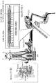
- FIG. 1 is a diagram showing the overall configuration of carbon monoxide production and utilization according to an embodiment of the present invention.
- FIG. 2 is a schematic partial diagram showing a configuration of a carbon dioxide reforming apparatus located in a bath according to an embodiment of the present invention.
- FIG. 3 is a diagram illustrating a carbon monoxide conversion rate of a carbon-containing by-product utilizing radiant heat according to an embodiment of the present invention.
- FIG. 4 is a diagram showing a carbon monoxide conversion rate of a carbon-containing by-product utilizing radiant heat and an iron-containing by-product according to an embodiment of the present invention.
- FIG. 5 shows a schematic diagram of a CO reforming reaction tube installed in a bath.
- first, second and third are used to describe various parts, components, regions, layers and/or sections, but are not limited thereto. These terms are only used to distinguish one part, component, region, layer or section from another part, component, region, layer or section. Accordingly, a first part, component, region, layer or section described below may be referred to as a second part, component, region, layer or section without departing from the scope of the present invention.
- % means% by weight, and 1 ppm is 0.0001% by weight.
- FIG. 1 is an overall configuration diagram of carbon monoxide production and utilization in molten iron production according to an embodiment of the present invention.
- the process of manufacturing molten iron in an integrated steel mill mainly relies on the blast furnace method, and most of the carbon monoxide generated from coal is used as a reducing agent for iron ore, so a huge amount of carbon dioxide is generated in the molten iron manufacturing process.
- a huge amount of carbon dioxide is generated in the molten iron manufacturing process.
- to produce 1 ton of steel products about 2.18 tons of carbon dioxide is generated, of which 80% is due to the use of coal in the molten iron manufacturing process.
- the price of coal for coking suitable for the blast furnace process has increased significantly due to the recent surge in the price of fuel in the steel industry, deteriorating the price competitiveness of the molten iron manufacturing process.
- FIG. 1 a method of selectively separating and recovering carbon dioxide from the blast furnace exhaust gas, reforming it into carbon monoxide, and re-injecting it into the blast furnace is shown in FIG. 1.
- the content of the carbon dioxide component of the exhaust gas in the blast furnace is about 20 - 25%, and the internal volume per minute blast 5000Nm 16,000Nm three or more cases of three or more carbon dioxide, and optionally separating and recovering the carbon dioxide only, in Figure 1 to switch to CO Carbon monoxide is produced by the suggested method.
- the temperature of the produced carbon monoxide is about 800°C, and the use of coke and PCI coal used as a reducing agent can be reduced by blowing the produced high-temperature carbon monoxide into the blast furnace.
- a method for manufacturing molten iron includes the steps of collecting carbon dioxide in exhaust gas generated from a blast furnace; Reforming the carbon dioxide into carbon monoxide; And reinjecting the carbon monoxide into the blast furnace. Including, and re-injecting the carbon monoxide into the blast furnace;
- the CO gas re-injection amount (Nm 3 /min) of [Equation 1] may be 500 or more to 1270 Nm 3 /min or less.
- the value of [Equation 1] may be 500 to 970 Nm 3 /min, and more specifically, the value of [Equation 1] may be 500 to 750 Nm 3 /min.
- the CO gas circulation rate of [Equation 2] may be 15 to 40%. Specifically, the value of [Equation 2] may be 16 to 32%, more specifically 24 to 32%, and more specifically 24 to 30%.
- the value of the CO gas circulation rate in [Equation 2] is less than 15% , there may be a problem that the effect of reducing CO 2 compared to the technology investment is insignificant, and when the value of the CO gas circulation rate is more than 40%, the amount of carbon monoxide is large. As a result, the total input gas blown into the blast furnace is reduced, and there may be a problem in that the oxygen load must be increased in order to preserve the reduced amount of heat energy.
- CO gas circulation rate (%) CO gas re-intake (Nm 3 /min)/[CO gas content in exhaust gas (Nm 3 /ton) X charter production (ton/day)]X(1440 min/1 day)X100[%]
- the CO gas conversion rate of [Equation 1] or [Equation 2] may be 35% or more to less than 85%.
- the carbon monoxide temperature may be 800°C or higher, specifically 800 to 1500°C, more specifically 900 to 1200°C, and more specifically 1000 to 1100°C.
- the pulverized coal injection amount (kr/ton-pig) according to the CO conversion rate of [Equation 3] may satisfy 100 to 170 kg/ton-pig.
- the value of Equation 2 may be 100 (kg/ton-pig) or more, specifically 170 to 100, and more specifically 170.3 (kg/ton-pig) to 100.295 (kg/ton-pig).
- the step of capturing carbon dioxide in the exhaust gas generated from the blast furnace is at least one method selected from the group consisting of PSA (Pressure Swing Adsorption), deep cooling, ammonia/amine absorption, adsorbent usage, MOF (metal organic framework), and membrane separation.
- PSA Pressure Swing Adsorption
- MOF metal organic framework
- the conversion rate from carbon dioxide to carbon monoxide may be 35% or more, specifically 35 to 85%. More specifically, the conversion rate may be 35 to 64%, more specifically 35 to 50%.
- the modified carbon monoxide may be recycled where a heat source is needed, such as drying of refractory materials in the hot water.
- FIG. 2 is a schematic partial configuration diagram of the production of carbon monoxide in a bath according to an embodiment of the present invention.
- sintered ore, coke, and limestone are introduced from the top of the blast furnace and gradually fall down.
- coke is combusted by hot air flowing into the bottom of the blast furnace, and carbon monoxide generated in this process causes a reduction reaction with iron ore to produce molten iron.
- the temperature of the resulting melt is 1,500°C or higher.
- radiant heat is released to the melt bath, and the temperature of radiant heat at this time is about 900°C ⁇ 1200°C.
- a carbon dioxide reforming device formed of a material having excellent conductivity is installed on the upper part of the melt, and carbon dioxide is blown.
- Carbon monoxide is converted into carbon monoxide by mixing carbon-containing by-products and iron-containing by-products in a certain ratio, and then filling the interior with the radiant heat of the melt.
- the carbon-containing by-product may supply a carbon source for reforming carbon dioxide into carbon monoxide, and the iron-containing by-product may serve as a reforming catalyst.
- the carbon dioxide reforming apparatus of one embodiment of the present invention may promote a Boudouard reaction between carbon dioxide and carbon-containing by-products to reform carbon dioxide into carbon monoxide as shown in the following reaction equation.
- a mixture of carbon-containing by-products and iron-containing by-products is filled therein, and the mixing ratio of the carbon-containing by-products and the iron-containing by-products is 10 to 50 iron-containing by-products based on 100% by weight of the carbon-containing by-products. It may be included in weight percent.
- the mixing ratio of the carbon-containing by-product and the iron-containing by-product in the mixture may be adjusted according to the iron-containing content of the iron-containing by-product.
- the iron-containing by-product may be 0 to 50% by weight based on 100% by weight of the carbon-containing by-product, specifically, 10 to 40% by weight, and more specifically 20 to 40% by weight.
- the specific surface area of the carbon-containing by-product may be 50 m 2 /g or more, specifically, the specific surface area may be 50 to 300 m 2 /g, more specifically 100 to 290 m 2 /g, more specifically 200 to 285 m 2 /g, more specifically 250 to 280 m 2 /g. If the specific surface area is less than 50 m 2 /g, there may be a problem that the reaction with the gas is significantly lowered and the reaction rate or conversion rate is lowered. If the specific surface area is too large, such as when the specific surface area is more than 300 m 2 /g, As it reacts with more gas, the reaction time is shortened, and there may be a problem that is difficult to control.
- the carbon component of the carbon-containing by-product may be 60% by weight or more, specifically, 80 to 90% by weight, and more specifically 82 to 87% by weight. If the carbon component of the carbon-containing by-product is less than 60% by weight, there may be a problem that the amount of converted gas decreases as the amount of carbon is reduced compared to the amount of gas to be blown. Therefore, there may be a problem in that there are many carbon components and deactivated carbon components exist.
- the iron-containing component of the iron-containing by-product may be 50% by weight or more, specifically 50 to 100% by weight, and more specifically 50 to 60% by weight.
- the active energy of the reaction is increased due to the decrease in the iron-containing component serving as a catalyst, thereby slowing the reaction rate, thereby lowering the conversion rate.
- the carbon dioxide reforming apparatus may be an apparatus for reforming carbon dioxide in exhaust gas generated from a blast furnace, and the carbon dioxide reforming apparatus may be installed in a molten material bath during an iron making process.
- the carbon dioxide reforming device may be installed in the melt bath during the iron making process to use radiant heat of the melt (see FIG. 5).
- the carbon dioxide reforming device may be a device in which one or more devices are installed over the entire area of the melt bath. In addition, it may be detachable depending on the operating conditions in the bath. In addition, since the carbon dioxide reforming apparatus is 1 or more, the carbon dioxide injection inlet may also be 1 or more.
- the reaction tube may be installed in a bundle form or a mesh network form to be fixed and connected.
- a cover is present on the melt, and the carbon dioxide reforming device may be present between the melt and the cover.
- the temperature of the air between the melt and the cover may be 900°C or higher, specifically 900 to 1500°C, and more specifically 900 to 1200°C. This high-temperature heat is transferred to the carbon dioxide reforming device, and the carbon dioxide reacts with the carbon-containing by-products to be reformed into carbon monoxide.
- the position of the carbon dioxide reforming device may be adjusted in consideration of the amount of melt in the bath. Specifically, the location of the carbon dioxide reforming device may be determined according to the temperature and amount of the melt flowing in the bath.
- the carbon dioxide reforming device when the melt flows in the melt bath, the carbon dioxide reforming device may be installed above 100 to 500 mm, specifically 200 to 400 mm from the top of the melt surface. If it is installed too close to the top of the melt surface, there may be a problem of deformation of the installed reaction tube, and if it is installed too far from the top of the melt surface, radiant heat is not sufficiently transferred and the temperature inside the reaction tube is high enough to react. There may be a problem that doesn't lose.
- the material of the carbon dioxide reforming device is sufficient as long as the radiant heat of the melt in the melt bath is well transferred, and may be at least one selected from the group consisting of tungsten, molybdenum, silicon carbide, and aluminum nitride, and specifically tungsten. .
- carbon dioxide gas in the exhaust gas in the blast furnace was reformed with carbon monoxide and re-injected into the blast furnace windpipe, and calculated by the thermal mass balance equation to determine the blast furnace heat balance and the carbon dioxide reduction effect.
- Table 1 shows the balance in the blast furnace and the effect of reducing carbon dioxide by re-injecting carbon monoxide into the blast furnace windpipe for each carbon monoxide gas conversion rate manufactured according to an embodiment of the present invention to the molten iron.
- *Base refers to an existing blast furnace that does not inject modified carbon monoxide.
- the circulation rate of carbon monoxide produced from Tangdo to the blast furnace punggu is 32.5% when the carbon monoxide conversion rate is 85%, the circulation rate is 24.9% when the conversion rate is 65%, and the circulation rate is 50%.
- the circulation rate was calculated as 13.4%.
- the amount of CO gas generated by reacting with carbon-containing by-products filled in the reactor installed inside the reactor and the CO 2 gas blown into the reactor is expressed as a conversion rate, and the amount of CO gas generated by this conversion rate is blown into the blast furnace fan.
- the amount of CO gas that can be replaced with respect to the total amount of air blown into the blast furnace windpipe is the circulation rate in consideration of the heat balance in the blast furnace.
- the reduction effect of reducing agent cost according to the carbon monoxide conversion rate was about 50 kg/tp pulverized coal when carbon monoxide with a conversion rate of 85% was introduced, and carbon saving was about 43 kg/tp, CO 2 reduction effect (CO 2 saving) was found to be about 156kg/tp.
- reinjecting carbon monoxide with a conversion rate of 85% increases the amount of carbon monoxide as the circulation rate is high, and accordingly, the total input gas blown into the blast furnace is reduced by about 20 Nm 3 /tp to preserve the reduced amount of thermal energy. It can be seen that there is a disadvantage of having to increase the oxygen load to do so.
- the CO gas with a conversion rate of 50% showed the closest value to the amount of air blown into the blast furnace, but the bosh gas volume, an index that determines the heat balance of the lower part of the blast furnace, was higher than that of the case of CO gas injection with a conversion rate of 30%. low. Accordingly, it can be seen that it is appropriate to re-inject carbon dioxide having a conversion rate of 35% into the blast furnace when maintaining the heat balance inside the blast furnace and considering the amount of carbon dioxide gas discharged outside the blast furnace.
- the CO gas conversion rate was varied as shown in Table 2 below, and the amount of exhaust gas generation and the production of chartered iron were kept constant.
- the amount of CO gas re-intake was calculated according to Equation 1 below.
- reinjecting carbon monoxide with a conversion rate of 85% has a disadvantage that the total input gas blown into the blast furnace is reduced and the oxygen load must be increased in order to preserve the amount of heat energy, so it is not desirable that the specific surface area is too large. You can see that it is not.
- the carbon-containing by-products there are by-products with a low specific surface area, so in order to increase the utilization of these by-products and further improve the carbon monoxide conversion rate, the carbon-containing by-products were mixed with the iron-containing by-products and filled in the reaction tube. Thereafter, the carbon monoxide conversion rate was measured using radiant heat from the bath.
- the mixing ratio of the iron-containing by-product is 10% by weight, 20% by weight, 30% by weight, 30% by weight, 40% by weight, and 60% by weight based on 100% by weight of the carbon-containing by-product. The results are shown in Table 4 and FIG. 4.
Landscapes
- Engineering & Computer Science (AREA)
- Chemical & Material Sciences (AREA)
- Manufacturing & Machinery (AREA)
- Materials Engineering (AREA)
- Metallurgy (AREA)
- Organic Chemistry (AREA)
- Waste-Gas Treatment And Other Accessory Devices For Furnaces (AREA)
- Carbon And Carbon Compounds (AREA)
- Manufacture Of Iron (AREA)
- Blast Furnaces (AREA)
Abstract
본 개시는 내부에 탄소함유 부산물 및 함철 부산물의 혼합물이 충진되어 있고, 상기 탄소함유 부산물과 함철 부산물의 혼합비는 탄소함유 부산물 100 중량%를 기준으로 함철 부산물을 0 내지 50 중량%로 포함되며, 이산화탄소를 일산화탄소로 개질시키는 이산화탄소 개질 장치 및 이 장치를 이용하여 고로 배가스 중의 이산화탄소를 재활용하는 용철 제조 시스템 및 용철 제조 방법에 관한 것이다.
Description
본 개시는 일산화탄소 제조방법에 관한 것이다. 보다 구체적으로 본 개시는 이산화탄소 배출을 저감하기 위하여 이산화탄소를 일산화탄소로 전환하고 이를 활용하는 방법에 관한 것이다.
제철산업에서의 환원공정은 용광로라 불리는 고로에서 코크스의 탄소와 철광석이 높은 온도로 인해 화학반응을 일으켜 액체상태의 철을 얻는 공정이다. 현재의 제선제강 공정의 문제는 이러한 환원공정을 위해 석탄과 같은 탄소계 환원제를 사용함으로써 필연적으로 다량의 이산화탄소(CO
2)가 발생하는 점이다. 하지만, 전 세계적으로 이산화탄소 배출 규제에 대한 압력이 거세지면서 철강업계는 환경, 에너지, 원가 경쟁력 측면에서 친환경 공정에 대한 관심이 증대되고 있다. 특히 교토 의정서 이후, CO
2 발생 저감 및 에너지 절약의 노력이 더욱 가속화 되고 있는 실정이다. 철강업의 경우에도 탄소세의 적용을 추진하고 있는 실정이므로, 최근 고로에 사용하고 있는 환원제비를 낮추는 방법과 배출되는 이산화탄소 저감에 대한 관심이 높아지고 있다.
용철을 제조하는 공정에서 이산화탄소 발생량을 저감하기 위하여는 용철 제조시 발생하는 배가스를 효율적으로 이용하는 것이 중요하다. 용철 제조시 발생되는 배가스의 주요성분으로는 CO, H
2, CO
2, H
2O, N
2 등이 있으며, 배가스 중 CO 및 H
2는 환원제 또는 열을 발생하는 열원으로 사용이 가능하다.
이에 고로에 사용되는 환원제비와 이산화탄소를 저감하기 위한 노력으로 고로 배가스 중 일산화탄소(CO) 만을 선택하여 고로에 재취입하는 기술, 탄소(석탄)를 대체하여 수소를 매개체로 활용하여 수소환원을 통하여 환원제비를 낮추고 이산화탄소 발생을 원천적으로 차단하려는 기술 등이 연구되고 있다. 하지만, 일산화탄소를 선택적으로 분리 회수하여 고로에 재취입하는 기술은 배가스 중 CO와 N
2의 분리회수 회수율이 낮은 문제가 있으며, 수소를 매개로 사용하는 수소환원기술은 경제성이 낮으며, 환원제를 사용하는 경우 조업의 변화를 예측할 수 없다는 문제점이 있다. 또한, 분리된 CO 가스 및 생산되니 수소가스를 고로에 재취입하기 위하여는 고로 내부의 열 밸런스를 고려하여 고로 송풍온도인 1200℃ 이상까지 승온시켜야 하는 문제가 있어 여전히 개발이 필요한 실정이다.
본 개시는 이러한 문제를 해결하기 위하여, 고로 배가스 중 이산화탄소를 선택적으로 분리하여 포집한 후 제철소 내 발생하는 부산물을 재활용하여 이산화탄소를 일산화탄소로 환원시키고, 제조된 일산화탄소를 고로에 재취입하는 방법을 제안하고자 한다.
본 발명의 일 구현예에 의한 용철 제조 방법은, 고로에서 발생한 배가스 내 이산화탄소를 포집하는 단계; 상기 이산화탄소를 일산화탄소로 개질하는 단계; 및 상기 일산화탄소를 상기 고로 내 재취입하는 단계; 를 포함하고, 상기 일산화탄소를 상기 고로 내 재취입하는 단계;에서, [식 1]의 CO 가스 재취입량 (Nm
3/분)은 500 이상 내지 1270 이하 일 수 있다.
[식 1] CO 가스 재취입량 (Nm
3/분)= 배가스 중 CO2 가스 함량(Nm
3/ton) X용선 생산량(ton/day) X 탕도내 투입되는 CO2가스 비율(50%)X CO 가스 전환율(%)X(1 day/1440 min)
상기 용철 제조 방법은, [식 2]의 CO 가스 순환율이 15 내지 40%일 수 있다.
[식 2] CO 가스 순환율(%) = CO 가스 재취입량 (Nm
3/분)/[배가스 중 CO 가스 함량(Nm
3/ton)X용선 생산량(ton/day)]X(1440 분/1 day)X100[%]
상기 [식 1] 또는 [식 2]의 CO 가스 전환율은 35% 이상 내지 85% 미만일 수 있다.
상기 일산화탄소를 상기 고로 내 재취입하는 단계;에서, 상기 일산화탄소의 온도는 800℃ 이상일 수 있다.
상기 일산화탄소를 상기 고로 내 재취입하는 단계;에서, [식 3]의 CO 전환율 에 따른 미분탄 취입량 (kr/ton-pig)은 100 내지 170 kg/ton-pig을 만족할 수 있다.
[식 3] CO 전환율에 따른 미분탄 취입량(kg/ton-pig) = -0.007*[CO전환율(%)]
2-0.00005*[CO 전환율(%)]+170.3
본 개시 일 구현예의 이산화탄소 개질 장치는 내부에 탄소함유 부산물 및 함철 부산물의 혼합물이 충진되어 있고, 상기 탄소함유 부산물과 함철 부산물의 혼합비는 탄소함유 부산물 100 중량%를 기준으로 함철 부산물을 10 내지 50 중량%로 포함되며, 이산화탄소를 일산화탄소로 개질하는 것일 수 있다.
상기 탄소함유 부산물의 비표면적은 50 m
2/g 이상일 수 있다.
상기 탄소 함유 부산물의 탄소 성분은 80 중량% 이상이고, 상기 함철 부산물의 함철 성분은 50 중량% 이상일 수 있다.
본 개시 일 구현예의 이산화탄소 개질 장치는, 고로에서 발생한 배가스 내 이산화탄소를 개질하는 장치이되, 상기 이산화탄소 개질 장치는 제철 공정 중의 용융물 탕도 내에 설치되는 것일 수 있다.
상기 이산화탄소 개질 장치는 1 이상의 장치가 용융물 탕도 면적 전반에 걸쳐 설치될 수 있다.
상기 이산화탄소 개질 장치가 2 이상인 경우, 반응관이 묶음 형태 또는 메쉬망 형태로 설치되어 고정되어 연결될 수 있다.
상기 용융물 탕도는 용융물 위에 커버가 존재하고, 상기 이산화탄소 개질 장치는 용융물과 커버 사이에 존재할 수 있다.
상기 용융물 탕도 내의 용융물과 커버 사이의 온도는 900℃ 이상일 수 있다.
상기 이산화탄소 개질 장치의 위치는 용융물 탕도 내 용융물의 양을 고려하여 조절될 수 있다.
본 발명의 일 구현예에 따르면, 이산화탄소 개질 장치에서 고로에서 포집된 이산화탄소를 일산화탄소로 개질시킬 수 있다.
또한, 본 발명의 일 구현예에 따르면, 이산화탄소 개질 장치를 용융물 탕도의 용융물 복사열을 이용하여 고로에 재취입시 고로내 에너지 밸런스를 유지시킬 수 있다.
또한, 본 발명의 일 구현예에 따르면, 고로 배가스 중 이산화탄소를 포집하여 사용하므로 이산화탄소 배출량을 저감할 수 있다.
또한, 본 발명의 일 구현예에 따르면, 제조된 일산화탄소를 고로에 재취입시킴으로써 환원제비를 저감시킬 수 있다.
도 1은 본 발명 일 구현예의 일산화탄소 제조 및 활용의 전체적인 구성도를 도시한 것이다.
도 2는 본 발명 일 구현예에 따른 탕도 내에 이산화탄소 개질 장치를 위치시킨 개략적인 일부 구성도를 도시한 것이다.
도 3은 본 발명 일 구현예에 따른 복사열 활용 탄소함유 부산물의 일산화탄소 전환율을 도시한 것이다.
도 4는 본 발명 일 구현예에 따른 복사열 활용 탄소함유 부산물과 함철 함유 부산물의 일산화탄소 전환율을 도시한 것이다.
도 5는 탕도내 설치되는 CO 개질 반응관의 모식도를 나타낸 것이다.
제1, 제2 및 제3 등의 용어들은 다양한 부분, 성분, 영역, 층 및/또는 섹션들을 설명하기 위해 사용되나 이들에 한정되지 않는다. 이들 용어들은 어느 부분, 성분, 영역, 층 또는 섹션을 다른 부분, 성분, 영역, 층 또는 섹션과 구별하기 위해서만 사용된다. 따라서, 이하에서 서술하는 제1 부분, 성분, 영역, 층 또는 섹션은 본 발명의 범위를 벗어나지 않는 범위 내에서 제2 부분, 성분, 영역, 층 또는 섹션으로 언급될 수 있다.
여기서 사용되는 전문 용어는 단지 특정 실시예를 언급하기 위한 것이며, 본 발명을 한정하는 것을 의도하지 않는다. 여기서 사용되는 단수 형태들은 문구들이 이와 명백히 반대의 의미를 나타내지 않는 한 복수 형태들도 포함한다. 명세서에서 사용되는 "포함하는"의 의미는 특정 특성, 영역, 정수, 단계, 동작, 요소 및/또는 성분을 구체화하며, 다른 특성, 영역, 정수, 단계, 동작, 요소 및/또는 성분의 존재나 부가를 제외시키는 것은 아니다.
어느 부분이 다른 부분의 "위에" 또는 "상에" 있다고 언급하는 경우, 이는 바로 다른 부분의 위에 또는 상에 있을 수 있거나 그 사이에 다른 부분이 수반될 수 있다. 대조적으로 어느 부분이 다른 부분의 "바로 위에" 있다고 언급하는 경우, 그 사이에 다른 부분이 개재되지 않는다.
또한, 특별히 언급하지 않는 한 %는 중량%를 의미하며, 1ppm 은 0.0001중량%이다.
다르게 정의하지는 않았지만, 여기에 사용되는 기술용어 및 과학용어를 포함하는 모든 용어들은 본 발명이 속하는 기술분야에서 통상의 지식을 가진 자가 일반적으로 이해하는 의미와 동일한 의미를 가진다. 보통 사용되는 사전에 정의된 용어들은 관련기술문헌과 현재 개시된 내용에 부합하는 의미를 가지는 것으로 추가 해석되고, 정의되지 않는 한 이상적이거나 매우 공식적인 의미로 해석되지 않는다.
이하, 본 발명의 실시예에 대하여 본 발명이 속하는 기술분야에서 통상의 지식을 가진 자가 용이하게 실시할 수 있도록 상세히 설명한다. 그러나 본 발명은 여러 가지 상이한 형태로 구현될 수 있으며 여기에서 설명하는 실시예에 한정되지 않는다.
도 1은 본 발명의 일 구현예에 따른 일산화탄소 제조 및 용철 제조에 활용의 전체적인 구성도이다. 현재 일관 제철소에서 용철을 제조하는 공정은 주로 고로 공법에 의존하고 있으며 대부분 철광석의 환원제로 석탄에서 발생한 일산화탄소를 사용하고 있어 막대한 양의 이산화탄소가 용철 제조 공정에서 발생하고 있다. 예를 들어, 1톤의 철강 제품을 생산 하기 위해서는 약 2.18톤의 이산화탄소가 발생하는데 이중 80%가 용철 제조 공정의 석탄사용에 기인하고 있다. 한편, 최근 제철산업의 연원료 가격 급등으로 고로 공정에 적합한 코킹(Coking)용 석탄가격이 크게 증가하여 용철제조 공정의 가격 경쟁력을 악화 시키고 있다. 이러한 문제를 해결하기 위해 고로 배가스 중 이산화탄소를 선택적으로 분리 회수하여 일산화탄소로 개질하여 다시 고로에 재취입하는 방법을 제안하고 이를 도 1에 도시한 것이다. 고로에서 배가스 성분 중 이산화탄소의 함량은 약 20~25%이며 내용적 5000Nm
3이상의 고로의 경우 분당 16,000Nm
3이상의 이산화탄소가 배출되고 있으며 이 이산화탄소만을 선택적으로 분리 회수하여, 일산화탄소로 전환하기 위해 도 1에서 제시한 방법으로 일산화탄소를 제조한다. 이때 제조된 일산화탄소의 온도는 약 800℃이며 제조된 고온의 일산화탄소를 고로 풍구에 취입하여 환원제로 사용되는 코크스와 PCI탄의 사용을 줄일 수 있다.
이하, 이산화탄소를 일산화탄소로 개질하여 재취입하는 용철 제조 방법에 대해 보다 구체적으로 살펴본다.
본 발명 일 구현예의 용철 제조 방법은, 고로에서 발생한 배가스 내 이산화탄소를 포집하는 단계; 상기 이산화탄소를 일산화탄소로 개질하는 단계; 및 상기 일산화탄소를 상기 고로 내 재취입하는 단계; 를 포함하고, 상기 일산화탄소를 상기 고로 내 재취입하는 단계;에서, [식 1]의 CO 가스 재취입량 (Nm
3/분)은 500 이상 내지 1270 Nm
3/분 이하 일 수 있다. 구체적으로 [식 1]의 값은 500 내지 970 Nm
3/분, 보다 구체적으로 [식 1]의 값은 500 내지 750 Nm
3/분일 수 있다. [식 1]의 값이 500 Nm
3/분 미만인 경우에는 기술 투자 대비 CO
2 저감 효과가 미미한 문제가 있을 수 있고, [식 1]의 값아 1270 Nm
3/분 초과인 경우에는 일산화탄소의 양이 많아지고 그에 따라 고로에 취입되는 송풍량 (Total Input Gas)가 줄어들고, 줄어든 만큼의 열에너지를 보존하기 위하여 산소 부하를 증가시켜야 하는 문제가 있을 수 있다.
[식 1] CO 가스 재취입량 (Nm
3/분)= 배가스 중 CO2 가스 함량(Nm
3/ton) X용선 생산량(ton/day) X 탕도내 투입되는 CO2가스 비율(50%)X CO 가스 전환율(%)X(1 day/1440 min)
상기 용철 제조 방법은, [식 2]의 CO 가스 순환율이 15 내지 40%일 수 있다. 구체적으로 [식 2]의 값은 16 내지 32%, 보다 구체적으로 24 내지 32%, 보다 구체적으로 24 내지 30%일 수 있다. [식 2]의 CO 가스 순환율의 값이 15% 미만인 경우에는 기술 투자 대비 CO
2 저감 효과가 미미한 문제가 있을 수 있고, CO 가스 순환율의 값이 40% 초과인 경우에는 일산화탄소의 양이 많아지고 그에 따라 고로에 취입되는 송풍량 (Total Input Gas)이 줄어들고, 줄어든 만큼의 열에너지를 보존하기 위하여 산소 부하를 증가시켜야 하는 문제가 있을 수 있다.
[식 2] CO 가스 순환율(%) = CO 가스 재취입량 (Nm
3/분)/[배가스 중 CO 가스 함량(Nm
3/ton)X용선 생산량(ton/day)]X(1440 분/1 day)X100[%]
상기 [식 1] 또는 [식 2]의 CO 가스 전환율은 35% 이상 내지 85% 미만일 수 있다.
상기 일산화탄소를 고로 내에 재취입하는 단계;에서, 상기 일산화탄소 온도는 800℃ 이상일 수 있고, 구체적으로 800 내지 1500℃, 보다 구체적으로 900 내지 1200℃, 보다 구체적으로 1000 내지 1100℃일 수 있다.
상기 일산화탄소를 상기 고로 내 재취입하는 단계;에서, [식 3]의 CO 전환율 에 따른 미분탄 취입량 (kr/ton-pig)은 100 내지 170 kg/ton-pig을 만족할 수 있다. 구체적으로 식 2의 값은 100(kg/ton-pig) 이상일 수 있고, 구체적으로 170 내지 100, 보다 구체적으로 170.3(kg/ton-pig) 내지 100.295(kg/ton-pig)일 수 있다. 상기 [식 3]의 미분탄 취입량이 100 kg/ton-pig 미만인 경우에는 노내 열량이 부족해지는 문제가 있수 있고, 170kg/ton-pig 초과인 경우에는 노내 통기 압박이 커져 미분탄비를 증대하거나 코크스 사용량을 줄여 환원제비를 저감하는 목적을 달성할 수 없는 문제가 있을 수 있다.
[식 3] CO 전환율에 따른 미분탄 취입량(kg/ton-pig) = -0.007*[CO전환율(%)]
2-0.00005*[CO 전환율(%)]+170.3
상기 고로에서 발생한 배가스 내 이산화탄소를 포집하는 단계;는 PSA (Pressure Swing Adsorption), 심냉법, 암모니아/아민 흡수법, 흡착제 사용법, MOF (Metal organic framework), 및 막 분리법으로 이루어진 군 중에서 선택된 1 이상의 방법으로 이산화탄소를 선택적으로 포집할 수 있다.
상기 이산화탄소로부터 일산화탄소로 개질되는 전환율은 35% 이상, 구체적으로 35 내지 85%일 수 있다. 보다 구체적으로, 전환율은 35 내지 64%, 보다 구체적으로 35 내지 50%일 수 있다.
상기 개질된 일산화탄소는 고로 풍구를 통하여 고로 내부로 재취입되는 것 외에도 탕도 내화물 건조 등과 같이 열원이 필요한 곳에 재활용 될 수 있다.
도 2는 본 발명의 일 구현예에 따른 탕도 내에서 일산화탄소 제조의 개략적인 일부 구성도이다. 일반적으로, 소결광, 코크스, 석회석은 고로 상부에서 투입되어 서서히 아래로 떨어진다. 이때, 코크스는 고로 밑부분에 유입되는 열풍에 의해 연소되는데, 이 과정에서 발생하는 일산화탄소가 철광석과 환원반응을 일으키면서 용선이 생산된다. 이때 생성된 용융물의 온도는 1,500℃ 이상이다. 이 온도에 의해 용융물 탕도에는 복사열이 방출되고 이때의 복사열의 온도는 약 900℃~1200℃이다. 이 용융물 상부에 전도율이 우수한 재질로 형성된 이산화탄소 개질 장치를 설치하고 이산화탄소를 취입한다. 이 내부에 제철 부산물 중 탄소 함유 부산물과 함철 부산물을 일정한 비율로 혼합 후 충진하여 용융물 복사열을 활용하여 이산화탄소를 일산화탄소로 개질한다. 상기 탄소 함유 부산물은 이산화탄소를 일산화탄소로 개질하는 탄소원을 공급하고, 함철 부산물은 개질 촉매로 작용할 수 있다.
이하 이산화탄소 개질 장치의 각 구성을 보다 구체적으로 살펴본다.
본 발명 일 구현예의 이산화탄소 개질 장치는, 이산화탄소와 탄소 함유 부산물 간의 부다 반응 (Boudouard reaction)을 촉진하여 하기 반응식과 같이 이산화탄소를 일산화탄소로 개질시킬 수 있다.
CO
2 + C → 2CO
본 발명 일 구현예의 이산화탄소 개질 장치는, 내부에 탄소함유 부산물 및 함철 부산물의 혼합물이 충진되어 있고, 상기 탄소함유 부산물과 함철 부산물의 혼합비는 탄소함유 부산물 100 중량%를 기준으로 함철 부산물을 10 내지 50 중량%로 포함될 수 있다.
상기 혼합물에서의 탄소함유 부산물과 함철 부산물의 혼합비는 함철 부산물 중의 함철 함량에 따라 조절될 수 있다. 구체적으로, 탄소함유 부산물 100 중량%를 기준으로 함철 부산물을 0 내지 50 중량%일 수 있고, 구체적으로, 10 내지 40 중량%, 보다 구체적으로 20 내지 40 중량%일 수 있다. 탄소함유 부산물 100 중량%에 대하여 함철 부산물을 50 중량% 초과하여 혼합하는 경우에는 CO
2 가스와 반응하는 탄소 함유 부산물의 표면을 과다하게 덮어버려 활성점으로 작용하는 CO
2 가스와 탄소 함유 부산물 경계면이 오히려 줄어드는 문제가 있을 수 있다.
상기 탄소함유 부산물의 비표면적은 50 m
2/g 이상일 수 있고, 구체적으로 비표면적은 50 내지 300 m
2/g 일 수 있고, 보다 구체적으로 100 내지 290 m
2/g, 보다 구체적으로 200 내지 285 m
2/g, 보다 구체적으로 250 내지 280 m
2/g일 수 있다. 비표면적이 50 m
2/g 미만인 경우에는 가스와의 반응이 현저하게 낮아져 반응율 혹은 전환율이 낮아지는 문제가 있을 수 있고, 비표면적이 300 m
2/g 초과인 경우와 같이 비표면적이 너무 크면, 더 많은 기체와 반응하게 되어 반응시간이 짧아져 제어가 곤란한 문제가 있을 수 있다.
상기 탄소 함유 부산물의 탄소 성분은 60 중량% 이상일 수 있고, 구체적으로, 80 내지 90 중량%, 보다 구체적으로 82 내지 87 중량%일 수 있다. 탄소 함유 부산물의 탄소 성분이 60 중량% 미만인 경우에는 취입하는 가스 양에 대비하여 탄소양이 줄어들어 전환된 가스량이 감소되는 문제가 있을 수 있고, 탄소 성분이 90 중량% 초과인 경우에는 취입되는 가스량 대비하여 탄소 성분이 많아 비활성화된 탄소성분이 존재하는 문제가 있을 수 있다.
상기 함철 부산물의 함철 성분은 50 중량% 이상일 수 있고, 구체적으로 50 내지 100 중량%, 보다 구체적으로 50 내지 60 중량%일 수 있다. 함철 부산물의 함철 성분이 50 중량% 미만인 경우에는 촉매의 역할을 하는 함철 성분의 감소로 인하여 반응의 활성에너지가 증대되어 반응속도가 느려져 전환율이 낮아지는 문제가 있을 수 있다.
또한, 본 발명 일 구현예의 이산화탄소 개질 장치는, 고로에서 발생한 배가스 내 이산화탄소를 개질하는 장치이되, 상기 이산화탄소 개질 장치는 제철 공정 중의 용융물 탕도 내에 설치되는 것일 수 있다. 상기 이산화탄소 개질 장치는 제철 공정 중의 용융물 탕도 내에 설치되어 용융물의 복사열을 이용할 수 있다 (도 5 참조).
상기 이산화탄소 개질 장치는 1 이상의 장치가 용융물 탕도 면적 전반에 걸쳐 설치되는 장치일 수 있다. 또한, 탕도 내의 조업 상황에 따라 탈부착이 가능할 수 있다. 또한, 이산화탄소 개질 장치가 1 이상임에 따라 이산화탄소 취입 입구 역시 1 이상일 수 있다.
상기 이산화탄소 개질 장치가 2 이상인 경우, 반응관이 묶음 형태 또는 메쉬망 형태로 설치되어 고정되어 연결될 수 있다.
상기 용융물 탕도는 용융물 위에 커버가 존재하고, 상기 이산화탄소 개질 장치는 용융물과 커버 사이에 존재하는 것일 수 있다.
상기 용융물과 커버 사이 공기의 온도는 900℃ 이상, 구체적으로 900 내지 1500℃, 보다 구체적으로 900 내지 1200℃일 수 있다. 이 고온의 열기가 이산화탄소 개질 장치에 전달되어 이산화탄소가 탄소 함유 부산물과 반응하여 일산화탄소로 개질되는 것이다.
상기 이산화탄소 개질 장치의 위치는 탕도 내 용융물의 양을 고려하여 조절될 수 있다. 구체적으로 이산화탄소 개질 장치의 위치는 탕도 내 흐르는 용융물의 온도와 양에 따라 정하여 질 수 있다.
구체적으로 용융물 탕도 내에 용융물이 흐르는 경우, 상기 이산화탄소 개질 장치는 용융물 표면 상부로부터 100 내지 500 mm, 구체적으로 200 내지 400 mm 위에 설치될 수 있다. 용융물 표면 상부로부터 너무 가까이 위에 설치되는 경우에는 설치된 반응관의 변형의 문제가 있을 수 있고, 용융물 표면 상부로부터 너무 떨어져 위에 설치되는 경우에는 복사열이 충분히 전달되지 않아 반응관 내부 온도가 반응할 만큼 충분히 높아지지 않는 문제가 있을 수 있다.
상기 이산화탄소 개질 장치의 소재는 용융물 탕도 내의 용융물의 복사열이 잘 전달되는 것이면 충분하고, 텅스텐, 몰리브덴, 실리콘카바이드, 및 질화알루미늄으로 이루어진 군 중에서 선택된 1종 이상일 수 있고, 구체적으로는 텅스텐일 수 있다.
이하에서는 실시예를 통하여 본 발명을 보다 상세하게 설명한다. 그러나, 이러한 실시예는 단지 본 발명을 예시하기 위한 것이며, 본 발명이 여기에 한정되는 것은 아니다.
실시예 1-일산화탄소 전환율에 따른 비교
본 발명에서 고로 내의 배가스 중에 이산화탄소 가스를 일산화탄소로 개질하여 고로 풍구로 재취입하여 고로 열 밸런스와 이산화탄소 저감효과를 알아보기 위하여 열물질 수지식으로 계산하였다. 표 1은 용선에 본 발명 일 실시예에 따라 제조된 일산화탄소 가스 전환율별로 고로 풍구에 일산화탄소 재취입에 따른 고로 내의 밸런스와 이산화탄소 저감 효과를 나타낸 것이다.

*Base는 개질된 일산화탄소를 주입하지 않는 기존 고로를 의미한다.
*t-p는 ton-pig를 의미한다.
[식 3] CO 전환율에 따른 미분탄 취입량(kg/ton-pig) = -0.007*[CO 전환율(%)]
2-0.00005*[CO 전환율(%)]+170.3
일산화탄소 각 전환율 별로 탕도에서 고로 풍구까지 제조된 일산화탄소의 순환율은 일산화탄소 전환율이 85%인 경우 순환율은 32.5%, 전환율이 65%인 경우 순환율은 24.9%, 전환율이 50%인 경우 순환율은 19.2%, 전환율이 35%인 경우 순환율이 13.4%로 계산되었다. 탕도내에 설치된 반응기 내부에 충진되어 있는 탄소함유 부산물과 반응기 내로 취입되는 CO
2 가스와 반응하여 생성된 CO 가스의 양을 전환율로 표현하며, 이 전환율별 생성된 CO 가스 양을 고로 풍구로 취입하기 위하여 고로내 열 발란스를 고려하여 고로 풍구에 취입되는 전체 송풍량에 대해 대체 가능한 CO가스의 양이 순환율이다.
일산화탄소 전환율에 따른 환원제비 저감 효과는 전환율이 85%인 일산화탄소 취입시 약 50 kg/t-p 미분탄 정도의 저감효과가 나타났고, 이때 탄소 저감(carbon saving)은 약 43kg/t-p, CO
2 저감효과 (CO
2 saving)는 약 156kg/t-p로 나타났다. 하지만 전환율이 85%인 일산화탄소를 재취입하는 것은 순환율이 높은 만큼 일산화탄소의 양이 많아지고 그에 따라 고로에 취입되는 송풍량(Total input gas)이 약 20 Nm
3/t-p 정도 줄어들어 줄어든 만큼의 열에너지를 보존하기 위하여 산소 부하를 증가시켜야 하는 단점이 있음을 알 수 있다. 또한 전환율 50%의 CO가스는 고로에 취입되는 송풍량이 가장 근접한 수치를 나타냈으나, 고로 하부의 열밸란스를 판단하는 지표인 보쉬 가스 부피(bosh gas volume)가 전환율 30% CO가스 취입의 경우보다 낮다. 이에, 고로 내부의 열 밸런스를 유지하고 고로 외로 배출되는 이산화탄소 가스 양을 고려하였을 때 전환율이 35%인 이산화탄소를 고로에 재취입하는 것이 적당한 것을 알 수 있다.
실시예 2 - 일산화탄소 전환율에 따른 CO 가스 재취입량
이산화탄소 전환율에 따라 고로 내에 재취입되는 CO 가스의 량을 알아 보는 실험을 진행하였다.
CO가스 전환율을 하기 표 2와 같이 달리하였으며, 배가스 발생량, 용선 생산량은 일정하게 유지하였다.
CO 가스 재 취입량은 하기 식 1에 따라 계산되었다.
[식 1] CO 가스 재취입량 (Nm
3/분)= 배가스 중 CO2 가스 함량(Nm
3/ton) X용선 생산량(ton/day) X 탕도내 투입되는 CO2가스 비율(50%)X CO 가스 전환율(%)X(1 day/1440 min)

상기 결과로부터 알 수 있듯이, CO 가스 재취입량이 1270 Nm
3/min을 초과하는 경우에는 그만큼 재취입되는 이산화탄소이 양이 많아지고 그에 따라 고로에 취입되는 송풍량이 줄어들게 되고 이를 표 에서 확인 할 수 있다. 결국 줄어든 송풍량만큼의 열에너지를 보존하기 위하여 산소 부하를 증가시켜야 하는 단점이 발생하게 될 것이다. 또한 CO 가스 재취입량이 500 Nm
3/min 미만인 경우에는 탄소 저감 또는 CO
2 저감 효과가 그만큼 저하되고 에너지 절약 및 환경 보호 효과를 달성하려는 본 발명의 궁극적인 목적에 부합하지 않게 된다.
실시예 3 - 탄소함유 부산물의 비표면적 비교
탕도내 복사열을 이용하여 이산화탄소 개질 장치에서 일산화탄소 제조하는 것을 구현하기 위하여 이산화탄소를 비표면적이 각각 표 3와 같이 상이한 탄소함유 부산물이 충진되어 있는 반응관에 각각 취입하여 온도에 따른 전환율을 측정하여 그 결과를 표 3에 나타내었다. 탕도 복사열에 의하여 반응 온도가 증가될수록 일산화탄소 전환율이 높아지는 것을 확인할 수 있으며, 같은 반응온도에서는 비표면적이 우수한 탄소함유 부산물의 전환율이 20% 더 우수한 것으로 관찰되었다 (도 3 참조). 다만, 전환율이 85%인 일산화탄소를 재취입하는 것은 고로에 취입되는 송풍량(Total input gas)이 줄어들어 그 만큼의 열에너지를 보존하기 위하여 산소 부하를 증가시켜야 하는 단점이 있으므로 비표면적이 너무 큰 것도 바람직하지 않음을 알 수 있다.

* 전환율 측정: 반응기에 취입되는 CO
2 부피 대비 생성된 CO의 부피
실시예 4 - 함철 함유 부산물 혼합비 비교
탄소함유 부산물 중에는 비표면적이 낮은 부산물이 존재하므로 이러한 부산물의 활용도를 높이고 일산화탄소 전환율을 더욱 향상시키기 위하여 탄소함유 부산물에 함철 부산물을 혼합하여 반응관에 충진하였다. 이후 일산화탄소 전환율을 탕도 복사열을 활용하여 측정하였다. 함철 부산물의 혼합비는 탄소 함유 부산물 100 중량%를 기준으로 10 중량%, 20 중량%, 30 중량%, 40 중량% 및 60중량%로 혼합하여, 함철 부산물을 혼합하지 않는 경우와 일산화탄소 전환율을 비교하여 그 결과를 표 4 및 도 4에 나타내었다. 그 결과 함철 부산물을 첨가한 경우가 첨가하지 않은 경우에 비하여 전환율이 우수함을 확인할 수 있었다. 아울러 함철 부산물의 비가 오히려 너무 커지는 경우에는 전환률이 떨어지는 것을 확인할 수 있었다.

본 발명은 실시예들에 한정되는 것이 아니라 서로 다른 다양한 형태로 제조될 수 있으며, 본 발명이 속하는 기술분야에서 통상의 지식을 가진 자는 본 발명의 기술적 사상이나 필수적인 특징을 변경하지 않고서 다른 구체적인 형태로 실시될 수 있다는 것을 이해할 수 있을 것이다. 그러므로 이상에서 기술한 실시예들은 모든 면에서 예시적인 것이며 한정적이 아닌 것으로 이해해야만 한다.
Claims (14)
- 고로에서 발생한 배가스 내 이산화탄소를 포집하는 단계;상기 이산화탄소를 일산화탄소로 개질하는 단계; 및상기 일산화탄소를 상기 고로 내 재취입하는 단계;를 포함하고,상기 일산화탄소를 상기 고로 내 재취입하는 단계;에서,[식 1]의 CO 가스 재취입량 (Nm 3/분)은 500 이상 내지 1270 이하를 만족하는, 용철 제조 방법.[식 1] CO 가스 재취입량 (Nm 3/분)= 배가스 중 CO2 가스 함량(Nm 3/ton) X용선 생산량(ton/day) X 탕도내 투입되는 CO2가스 비율(50%)X CO 가스 전환율(%)X(1 day/1440 min)
- 제1항에 있어서,상기 용철 제조 방법은, [식 2]의 CO 가스 순환율이 15 내지 40%인, 용철 제조 방법.[식 2] CO 가스 순환율(%) = CO 가스 재취입량 (Nm 3/분)/[배가스 중 CO 가스 함량(Nm 3/ton)X용선 생산량(ton/day)]X(1440 분/1 day)X100[%]
- 제1항에 있어서,상기 [식 1]의 CO 가스 전환율은 35% 이상 내지 85% 미만인, 용철 제조 방법.
- 제1항에 있어서,상기 일산화탄소를 상기 고로 내 재취입하는 단계;에서,상기 일산화탄소의 온도는 800℃ 이상인, 용철 제조 방법.
- 제1항에 있어서,상기 일산화탄소를 상기 고로 내 재취입하는 단계;에서, [식 3]의 CO 전환율 에 따른 미분탄 취입량 (kr/ton-pig)은 100 내지 170 kg/ton-pig을 만족하는, 용철 제조 방법.[식 3] CO 전환율에 따른 미분탄 취입량(kg/ton-pig) = -0.007*[CO전환율(%)] 2-0.00005*[CO 전환율(%)]+170.3
- 내부에 탄소함유 부산물 및 함철 부산물의 혼합물이 충진되어 있고,상기 탄소함유 부산물과 함철 부산물의 혼합비는 탄소함유 부산물 100 중량%를 기준으로 함철 부산물을 10 내지 50 중량%로 포함되며,이산화탄소를 일산화탄소로 개질하는, 이산화탄소 개질 장치.
- 제6항에 있어서,상기 탄소함유 부산물의 비표면적은 50 m 2/g 이상인, 이산화탄소 개질 장치.
- 제6항에 있어서,상기 탄소 함유 부산물의 탄소 성분은 80 중량% 이상이고,상기 함철 부산물의 함철 성분은 50 중량% 이상인, 이산화탄소 개질 장치.
- 고로에서 발생한 배가스 내 이산화탄소를 개질하는 장치이되,상기 이산화탄소 개질 장치는 제철 공정 중의 용융물 탕도 내에 설치되는 것인, 이산화탄소 개질 장치.
- 제9항에 있어서,상기 이산화탄소 개질 장치는 1 이상의 장치가 용융물 탕도 면적 전반에 걸쳐 설치되는 장치인, 이산화탄소 개질 장치.
- 제9항에 있어서,상기 이산화탄소 개질 장치가 2 이상인 경우,반응관이 묶음 형태 또는 메쉬망 형태로 설치되어 고정되어 연결된, 이산화탄소 개질 장치.
- 제9항에 있어서,상기 용융물 탕도는 용융물 위에 커버가 존재하고,상기 이산화탄소 개질 장치는 용융물과 커버 사이에 존재하는, 이산화탄소 개질 장치.
- 제12항에 있어서,상기 용융물 탕도 내의 용융물과 커버 사이의 온도는 900℃ 이상인, 이산화탄소 개질 장치.
- 제9항에 있어서,상기 이산화탄소 개질 장치의 위치는 용융물 탕도 내 용융물의 양을 고려하여 조절되는 것인, 이산화탄소 개질 장치.
Priority Applications (3)
| Application Number | Priority Date | Filing Date | Title |
|---|---|---|---|
| CN202080080444.4A CN114729407A (zh) | 2019-11-20 | 2020-11-16 | 一氧化碳生产方法及其应用 |
| JP2022529655A JP7307858B2 (ja) | 2019-11-20 | 2020-11-16 | 一酸化炭素製造方法およびその活用 |
| EP20889482.4A EP4063524A4 (en) | 2019-11-20 | 2020-11-16 | METHOD FOR PRODUCTION OF CARBON MONOXIDE AND USE THEREOF |
Applications Claiming Priority (2)
| Application Number | Priority Date | Filing Date | Title |
|---|---|---|---|
| KR1020190149711A KR102322712B1 (ko) | 2019-11-20 | 2019-11-20 | 일산화탄소 제조방법 및 그 활용 |
| KR10-2019-0149711 | 2019-11-20 |
Publications (1)
| Publication Number | Publication Date |
|---|---|
| WO2021101193A1 true WO2021101193A1 (ko) | 2021-05-27 |
Family
ID=75980865
Family Applications (1)
| Application Number | Title | Priority Date | Filing Date |
|---|---|---|---|
| PCT/KR2020/016101 Ceased WO2021101193A1 (ko) | 2019-11-20 | 2020-11-16 | 일산화탄소 제조방법 및 그 활용 |
Country Status (5)
| Country | Link |
|---|---|
| EP (1) | EP4063524A4 (ko) |
| JP (1) | JP7307858B2 (ko) |
| KR (1) | KR102322712B1 (ko) |
| CN (1) | CN114729407A (ko) |
| WO (1) | WO2021101193A1 (ko) |
Cited By (2)
| Publication number | Priority date | Publication date | Assignee | Title |
|---|---|---|---|---|
| CN114317853A (zh) * | 2022-01-17 | 2022-04-12 | 新疆八一钢铁股份有限公司 | 一种基于2500m3高炉煤气碳循环喷吹高温煤气的加热方法 |
| CN114634831A (zh) * | 2022-03-25 | 2022-06-17 | 新疆八一钢铁股份有限公司 | 一种高炉喷吹等离子矩重整循环冶金煤气的工艺方法 |
Families Citing this family (1)
| Publication number | Priority date | Publication date | Assignee | Title |
|---|---|---|---|---|
| KR102907706B1 (ko) * | 2024-03-21 | 2026-01-06 | 한국공학대학교산학협력단 | 용해로를 이용하여 이산화탄소로부터 일산화탄소를 생성하는 방법 |
Citations (5)
| Publication number | Priority date | Publication date | Assignee | Title |
|---|---|---|---|---|
| KR20120060001A (ko) * | 2010-12-01 | 2012-06-11 | 주식회사 포스코 | 부생가스의 이산화탄소 개질 장치 및 개질 방법 |
| KR20130134365A (ko) * | 2012-05-31 | 2013-12-10 | 현대제철 주식회사 | 주선기용 발전장치 |
| US20140130639A1 (en) * | 2011-06-20 | 2014-05-15 | Siemens Aktiengesellschaft | Carbon dioxide reduction in steelworks |
| JP2016155702A (ja) * | 2015-02-24 | 2016-09-01 | Jfeスチール株式会社 | 炭化水素の二酸化炭素改質方法 |
| JP2017024957A (ja) * | 2015-07-27 | 2017-02-02 | Jfeスチール株式会社 | 炭化水素の二酸化炭素改質方法、炭化水素の二酸化炭素改質装置ならびに一酸化炭素および水素の製造方法 |
Family Cites Families (7)
| Publication number | Priority date | Publication date | Assignee | Title |
|---|---|---|---|---|
| CA2721329C (en) * | 2008-05-16 | 2012-04-10 | Jfe Steel Corporation | Method for reforming exhaust gas generated from metallurgical furnace, method for cooling exhaust gas and apparatus therefor |
| KR101285786B1 (ko) * | 2011-12-22 | 2013-07-22 | 주식회사 포스코 | 용융 슬래그를 이용한 이산화탄소 저감 장치 |
| EP2935517B1 (de) * | 2012-12-18 | 2018-03-21 | Basf Se | Verfahren zur verwertung von kuppelgasen, begleitgasen und/oder biogasen |
| PL2886666T3 (pl) * | 2013-12-20 | 2019-01-31 | L'air Liquide, Societe Anonyme Pour L'etude Et L'exploitation Des Procedes Georges Claude | Sposób działania instalacji wielkiego pieca z recyklingiem gazu gardzielowego |
| US9840756B1 (en) * | 2014-10-17 | 2017-12-12 | U.S. Department Of Energy | System and method for regeneration and recirculation of a reducing agent using highly exothermic reactions induced by mixed industrial slags |
| KR101758521B1 (ko) * | 2015-12-23 | 2017-07-17 | 주식회사 포스코 | 열풍로를 이용한 이산화탄소 분해 및 재활용 방법 |
| CN105671228B (zh) * | 2016-02-29 | 2018-02-27 | 神雾科技集团股份有限公司 | 氧气高炉与气基竖炉联合生产系统和联合生产方法 |
-
2019
- 2019-11-20 KR KR1020190149711A patent/KR102322712B1/ko active Active
-
2020
- 2020-11-16 JP JP2022529655A patent/JP7307858B2/ja active Active
- 2020-11-16 WO PCT/KR2020/016101 patent/WO2021101193A1/ko not_active Ceased
- 2020-11-16 EP EP20889482.4A patent/EP4063524A4/en active Pending
- 2020-11-16 CN CN202080080444.4A patent/CN114729407A/zh active Pending
Patent Citations (5)
| Publication number | Priority date | Publication date | Assignee | Title |
|---|---|---|---|---|
| KR20120060001A (ko) * | 2010-12-01 | 2012-06-11 | 주식회사 포스코 | 부생가스의 이산화탄소 개질 장치 및 개질 방법 |
| US20140130639A1 (en) * | 2011-06-20 | 2014-05-15 | Siemens Aktiengesellschaft | Carbon dioxide reduction in steelworks |
| KR20130134365A (ko) * | 2012-05-31 | 2013-12-10 | 현대제철 주식회사 | 주선기용 발전장치 |
| JP2016155702A (ja) * | 2015-02-24 | 2016-09-01 | Jfeスチール株式会社 | 炭化水素の二酸化炭素改質方法 |
| JP2017024957A (ja) * | 2015-07-27 | 2017-02-02 | Jfeスチール株式会社 | 炭化水素の二酸化炭素改質方法、炭化水素の二酸化炭素改質装置ならびに一酸化炭素および水素の製造方法 |
Non-Patent Citations (1)
| Title |
|---|
| See also references of EP4063524A4 * |
Cited By (2)
| Publication number | Priority date | Publication date | Assignee | Title |
|---|---|---|---|---|
| CN114317853A (zh) * | 2022-01-17 | 2022-04-12 | 新疆八一钢铁股份有限公司 | 一种基于2500m3高炉煤气碳循环喷吹高温煤气的加热方法 |
| CN114634831A (zh) * | 2022-03-25 | 2022-06-17 | 新疆八一钢铁股份有限公司 | 一种高炉喷吹等离子矩重整循环冶金煤气的工艺方法 |
Also Published As
| Publication number | Publication date |
|---|---|
| JP7307858B2 (ja) | 2023-07-12 |
| EP4063524A4 (en) | 2023-05-10 |
| JP2023503296A (ja) | 2023-01-27 |
| EP4063524A1 (en) | 2022-09-28 |
| CN114729407A (zh) | 2022-07-08 |
| KR102322712B1 (ko) | 2021-11-04 |
| KR20210061773A (ko) | 2021-05-28 |
Similar Documents
| Publication | Publication Date | Title |
|---|---|---|
| WO2021101193A1 (ko) | 일산화탄소 제조방법 및 그 활용 | |
| CN102010924B (zh) | 一种用煤生产直接还原铁的方法 | |
| WO2011087199A1 (ko) | 이산화탄소 발생량을 저감하는 용철 제조 장치 | |
| WO2013035998A2 (ko) | 일산화탄소 및 수소를 포함하는 합성가스 제조장치 및 그의 제조방법 | |
| WO2011081276A1 (ko) | 용철 제조 장치 | |
| WO2014104596A1 (ko) | 용철제조장치 및 용철제조방법 | |
| WO2017111415A1 (ko) | 열풍로를 이용한 이산화탄소 분해 및 재활용 방법 | |
| WO2014098300A1 (ko) | 환원철 제조방법 및 제조장치 | |
| WO2018004070A1 (ko) | 용철 제조장치 및 이를 이용한 용철 제조방법 | |
| JP2018521228A (ja) | ガス作り急速製鉄システム及び方法 | |
| CN213507040U (zh) | 一种铁矿粉循环还原生产直接还原铁的装置 | |
| CN113969329A (zh) | 降低二氧化碳排放的金属还原冶炼方法及系统 | |
| CN117107005B (zh) | 一种煤气化悬浮熔融炼铁装置和方法 | |
| CN220503099U (zh) | 一种煤气化悬浮熔融炼铁装置 | |
| WO2013094864A1 (ko) | 용철제조장치 및 용철제조방법 | |
| CN101818218B (zh) | 强化高炉间接还原的方法 | |
| JP7809209B2 (ja) | 製鋼方法及び関連するプラントのネットワーク | |
| WO2012091422A2 (ko) | 원자로를 이용한 환원철 제조장치 및 이를 이용한 환원철 제조방법 | |
| CN108707710A (zh) | 一种焦炉烟气资源处理和利用的方法 | |
| WO2019039666A1 (ko) | 용선 제조 설비 및 용선 제조 방법 | |
| WO2020105901A1 (ko) | 용철 제조 장치 | |
| CN113913571A (zh) | 使用冶金渣分离高炉煤气中二氧化碳的装置及其分离方法 | |
| CN207121422U (zh) | 一种气基竖炉还原气的制备系统 | |
| JP7700980B1 (ja) | 還元炉の操業方法および還元鉄の製造方法 | |
| WO2019124859A1 (ko) | 용선 제조장치 및 용선 제조방법 |
Legal Events
| Date | Code | Title | Description |
|---|---|---|---|
| 121 | Ep: the epo has been informed by wipo that ep was designated in this application |
Ref document number: 20889482 Country of ref document: EP Kind code of ref document: A1 |
|
| ENP | Entry into the national phase |
Ref document number: 2022529655 Country of ref document: JP Kind code of ref document: A |
|
| NENP | Non-entry into the national phase |
Ref country code: DE |
|
| ENP | Entry into the national phase |
Ref document number: 2020889482 Country of ref document: EP Effective date: 20220620 |