WO2021106284A1 - 漏電検出装置、車両用電源システム - Google Patents
漏電検出装置、車両用電源システム Download PDFInfo
- Publication number
- WO2021106284A1 WO2021106284A1 PCT/JP2020/031045 JP2020031045W WO2021106284A1 WO 2021106284 A1 WO2021106284 A1 WO 2021106284A1 JP 2020031045 W JP2020031045 W JP 2020031045W WO 2021106284 A1 WO2021106284 A1 WO 2021106284A1
- Authority
- WO
- WIPO (PCT)
- Prior art keywords
- voltage
- unit
- coupling capacitor
- resistor
- vehicle
- Prior art date
- Legal status (The legal status is an assumption and is not a legal conclusion. Google has not performed a legal analysis and makes no representation as to the accuracy of the status listed.)
- Ceased
Links
Images


Classifications
-
- H—ELECTRICITY
- H02—GENERATION; CONVERSION OR DISTRIBUTION OF ELECTRIC POWER
- H02H—EMERGENCY PROTECTIVE CIRCUIT ARRANGEMENTS
- H02H3/00—Emergency protective circuit arrangements for automatic disconnection directly responsive to an undesired change from normal electric working condition with or without subsequent reconnection ; integrated protection
- H02H3/16—Emergency protective circuit arrangements for automatic disconnection directly responsive to an undesired change from normal electric working condition with or without subsequent reconnection ; integrated protection responsive to fault current to earth, frame or mass
- H02H3/17—Emergency protective circuit arrangements for automatic disconnection directly responsive to an undesired change from normal electric working condition with or without subsequent reconnection ; integrated protection responsive to fault current to earth, frame or mass by means of an auxiliary voltage injected into the installation to be protected
-
- G—PHYSICS
- G01—MEASURING; TESTING
- G01R—MEASURING ELECTRIC VARIABLES; MEASURING MAGNETIC VARIABLES
- G01R31/00—Arrangements for testing electric properties; Arrangements for locating electric faults; Arrangements for electrical testing characterised by what is being tested not provided for elsewhere
- G01R31/50—Testing of electric apparatus, lines, cables or components for short-circuits, continuity, leakage current or incorrect line connections
- G01R31/52—Testing for short-circuits, leakage current or ground faults
-
- B—PERFORMING OPERATIONS; TRANSPORTING
- B60—VEHICLES IN GENERAL
- B60L—PROPULSION OF ELECTRICALLY-PROPELLED VEHICLES; SUPPLYING ELECTRIC POWER FOR AUXILIARY EQUIPMENT OF ELECTRICALLY-PROPELLED VEHICLES; ELECTRODYNAMIC BRAKE SYSTEMS FOR VEHICLES IN GENERAL; MAGNETIC SUSPENSION OR LEVITATION FOR VEHICLES; MONITORING OPERATING VARIABLES OF ELECTRICALLY-PROPELLED VEHICLES; ELECTRIC SAFETY DEVICES FOR ELECTRICALLY-PROPELLED VEHICLES
- B60L3/00—Electric devices on electrically-propelled vehicles for safety purposes; Monitoring operating variables, e.g. speed, deceleration or energy consumption
- B60L3/0023—Detecting, eliminating, remedying or compensating for drive train abnormalities, e.g. failures within the drive train
-
- B—PERFORMING OPERATIONS; TRANSPORTING
- B60—VEHICLES IN GENERAL
- B60L—PROPULSION OF ELECTRICALLY-PROPELLED VEHICLES; SUPPLYING ELECTRIC POWER FOR AUXILIARY EQUIPMENT OF ELECTRICALLY-PROPELLED VEHICLES; ELECTRODYNAMIC BRAKE SYSTEMS FOR VEHICLES IN GENERAL; MAGNETIC SUSPENSION OR LEVITATION FOR VEHICLES; MONITORING OPERATING VARIABLES OF ELECTRICALLY-PROPELLED VEHICLES; ELECTRIC SAFETY DEVICES FOR ELECTRICALLY-PROPELLED VEHICLES
- B60L3/00—Electric devices on electrically-propelled vehicles for safety purposes; Monitoring operating variables, e.g. speed, deceleration or energy consumption
- B60L3/0023—Detecting, eliminating, remedying or compensating for drive train abnormalities, e.g. failures within the drive train
- B60L3/0069—Detecting, eliminating, remedying or compensating for drive train abnormalities, e.g. failures within the drive train relating to the isolation, e.g. ground fault or leak current
-
- G—PHYSICS
- G01—MEASURING; TESTING
- G01R—MEASURING ELECTRIC VARIABLES; MEASURING MAGNETIC VARIABLES
- G01R19/00—Arrangements for measuring currents or voltages or for indicating presence or sign thereof
- G01R19/165—Indicating that current or voltage is either above or below a predetermined value or within or outside a predetermined range of values
- G01R19/16566—Circuits and arrangements for comparing voltage or current with one or several thresholds and for indicating the result not covered by subgroups G01R19/16504, G01R19/16528, G01R19/16533
- G01R19/16576—Circuits and arrangements for comparing voltage or current with one or several thresholds and for indicating the result not covered by subgroups G01R19/16504, G01R19/16528, G01R19/16533 comparing DC or AC voltage with one threshold
-
- G—PHYSICS
- G01—MEASURING; TESTING
- G01R—MEASURING ELECTRIC VARIABLES; MEASURING MAGNETIC VARIABLES
- G01R31/00—Arrangements for testing electric properties; Arrangements for locating electric faults; Arrangements for electrical testing characterised by what is being tested not provided for elsewhere
- G01R31/005—Testing of electric installations on transport means
- G01R31/006—Testing of electric installations on transport means on road vehicles, e.g. automobiles or trucks
-
- G—PHYSICS
- G01—MEASURING; TESTING
- G01R—MEASURING ELECTRIC VARIABLES; MEASURING MAGNETIC VARIABLES
- G01R31/00—Arrangements for testing electric properties; Arrangements for locating electric faults; Arrangements for electrical testing characterised by what is being tested not provided for elsewhere
- G01R31/01—Subjecting similar articles in turn to test, e.g. "go/no-go" tests in mass production; Testing objects at points as they pass through a testing station
- G01R31/013—Testing passive components
- G01R31/016—Testing of capacitors
-
- H—ELECTRICITY
- H02—GENERATION; CONVERSION OR DISTRIBUTION OF ELECTRIC POWER
- H02H—EMERGENCY PROTECTIVE CIRCUIT ARRANGEMENTS
- H02H3/00—Emergency protective circuit arrangements for automatic disconnection directly responsive to an undesired change from normal electric working condition with or without subsequent reconnection ; integrated protection
- H02H3/02—Details
- H02H3/04—Details with warning or supervision in addition to disconnection, e.g. for indicating that protective apparatus has functioned
- H02H3/044—Checking correct functioning of protective arrangements, e.g. by simulating a fault
Definitions
- the present invention relates to an earth leakage detection device for detecting an earth leakage of a load insulated from the ground, and a power supply system for a vehicle.
- HVs hybrid vehicles
- PSVs plug-in hybrid vehicles
- EVs electric vehicles
- traction battery auxiliary battery
- auxiliary battery generally a 12V output lead battery
- a high-voltage circuit including a high-voltage drive battery, an inverter, and a traveling motor is insulated from the vehicle body (chassis ground).
- Y capacitors are inserted between the positive wiring on the vehicle side of the high-voltage circuit and the chassis ground, and between the negative wiring on the vehicle side of the high-voltage circuit and the chassis ground, respectively, and are supplied to the load on the vehicle side from the high-voltage drive battery.
- the power supply is stabilized.
- An earth leakage detection device that monitors the insulation resistance between the high-power circuit and the chassis ground to detect an earth leakage is installed.
- a pulse voltage is applied to the positive electrode terminal or the negative electrode terminal of the drive battery via a resistor and a coupling capacitor, and the voltage at the connection point between the resistor and the coupling capacitor is measured. Detects the presence or absence of electric leakage.
- the AC type earth leakage detection device as a method of diagnosing a failure of the coupling capacitor, there is a method of diagnosing based on the fluctuation of the peak value when the relay (contactor) between the battery side and the vehicle side is opened and closed.
- the fluctuation of the crest value is equal to or less than the specified value, it is determined that an abnormality has occurred in the coupling capacitor (see, for example, Patent Document 1).
- the present disclosure has been made in view of such a situation, and an object thereof is to provide a technique for quickly and accurately diagnosing a failure of a coupling capacitor of an earth leakage detection device.
- the electric leakage detection device of a certain aspect of the present disclosure is mounted in a state of being insulated from the chassis ground of the vehicle, and includes a power storage unit that supplies power to the load in the vehicle and the power storage unit.
- a leak detection device mounted on a vehicle equipped with a switch inserted into the wiring connecting the load, one end of which is connected to the current path of the power storage unit connected to the load while being insulated from the ground.
- the voltage at the connection point between, the second and third resistors connected in series between the predetermined fixed potential, and the voltage dividing point between the second resistor and the third resistor In a state where the periodic voltage is output from the voltage measuring unit and the voltage output unit, the presence or absence of leakage between the current path of the power storage unit and the ground is determined based on the voltage measured by the voltage measuring unit.
- the switch When the switch is turned on in a state where a fixed voltage is output from the leakage determination unit and the voltage output unit, the coupling capacitor is set based on the voltage measured by the voltage measurement unit. It is provided with a diagnostic unit for determining whether or not it is normal.
- failure diagnosis of the coupling capacitor of the leakage detection device can be performed quickly and with high accuracy.
- FIG. 1 is a diagram for explaining a configuration of a power supply system 5 including an earth leakage detection device 10 according to a comparative example.
- the power supply system 5 is mounted on an electric vehicle.
- the power supply system 5 is provided separately from the auxiliary battery (usually, a lead battery having a 12V output is used) in the electric vehicle.
- the power supply system 5 includes a high-voltage power storage unit 20 and an earth leakage detection device 10.
- the power storage unit 20 includes a plurality of cells E1-En connected in series.
- As the cell a lithium ion battery cell, a nickel hydrogen battery cell, a lead battery cell, an electric double layer capacitor cell, a lithium ion capacitor cell, or the like can be used.
- a lithium ion battery cell nominal voltage: 3.6-3.7 V
- the electric vehicle is equipped with an inverter 2 and a motor 3 as a high voltage load.
- the positive electrode of the power storage unit 20 and one end of the inverter 2 are connected by the positive wiring Lp, and the negative electrode of the power storage unit 20 and the other end of the inverter 2 are connected by the negative wiring Lm.
- a large-capacity capacitor 4 is connected in parallel with the inverter 2.
- the positive main relay MRp is inserted into the positive wiring Lp
- the negative main relay MRm is inserted into the negative wiring Lm.
- the precharge relay MRpp connected in series and the precharge resistor Rp are connected in parallel with the main relay MRp on the positive side.
- the capacitor 4 can be precharged with a limited current and the inrush current is suppressed. be able to.
- the precharge relay and the precharge resistor connected in series may be connected in parallel with the negative main relay MRm.
- the positive side main relay MRp, the precharge relay MRpp, and the negative side main relay MRm function as contactors for controlling conduction / disconnection between the power storage unit 20 and the high voltage load in the electric vehicle. It is also possible to use a semiconductor switch with high withstand voltage and high insulation instead of the relay.
- the inverter 2 is a bidirectional inverter connected between the power storage unit 20 and the motor 3.
- the inverter 2 converts the DC power supplied from the power storage unit 20 into AC power and supplies it to the motor 3 during power running. At the time of regeneration, the AC power supplied from the motor 3 is converted into DC power and supplied to the power storage unit 20.
- the motor 3 for example, a three-phase AC motor is used.
- the motor 3 rotates according to the AC power supplied from the inverter 2 during power running. At the time of regeneration, the rotational energy due to deceleration is converted into AC power and supplied to the inverter 2.
- the power storage unit 20 is mounted on the electric vehicle in a state of being insulated from the chassis ground of the electric vehicle.
- the auxiliary battery is mounted on the electric vehicle with the negative electrode conducting with the chassis ground.
- From the positive main relay MRp the positive wiring Lp on the inverter 2 side and the chassis ground are connected via the positive Y capacitor Cp.
- the negative wiring Lm on the inverter 2 side and the chassis ground are connected via the negative side Y capacitor Cm.
- the positive Y capacitor Cp and the negative Y capacitor Cm insulate the positive wiring Lp and the chassis ground, and the negative wiring Lm and the chassis ground in a direct current manner, and stabilize the voltages of the positive wiring Lp and the negative wiring Lm, respectively. Has the effect of causing.
- the intermediate potential of the power storage unit 20 is maintained near the potential of the chassis ground.
- the positive electrode potential of the power storage unit 20 is maintained at around + 125V and the negative electrode potential is maintained at around -125V.
- the insulation state between the positive wiring Lp and the chassis ground is represented by the positive leakage resistance Rlp
- the insulation state between the negative wiring Lm and the chassis ground is represented by the negative leakage resistance Rlm.
- the leakage detection device 10 includes a coupling capacitor Cc, a first resistor R1, a first operational amplifier OP1, a second resistor R2, a smoothing capacitor C1, a second operational amplifier OP2, and a control unit 11.
- the control unit 11 includes an oscillation unit 11a, a voltage measurement unit 11b, an earth leakage determination unit 11c, and a diagnosis unit 11d.
- the control unit 11 can be composed of, for example, a microcomputer and a non-volatile memory (for example, EEPROM, flash memory).
- One end of the coupling capacitor Cc is connected to the current path of the power storage unit 20.
- one end of the coupling capacitor Cc is connected to the negative electrode of the power storage unit 20.
- One end of the coupling capacitor Cc may be connected to the positive electrode of the power storage unit 20, or may be connected to any node of a plurality of cells E1-En in the power storage unit 20.
- the other end of the coupling capacitor Cc is connected to the output end of the voltage output unit via the first resistor R1.
- the connection point between the other end of the coupling capacitor Cc and the first resistor R1 is the measurement point A.
- another impedance element may be used instead of the 1st resistor R1.
- an aluminum electrolytic capacitor that can increase the capacity at a relatively low cost is used for the coupling capacitor Cc.
- the aluminum electrolytic capacitor has polarity, and in FIG. 1, the positive electrode of the aluminum electrolytic capacitor is connected to the measurement point A, and the negative electrode of the aluminum electrolytic capacitor is connected to the negative electrode of the power storage unit 20.
- the coupling capacitor Cc may be configured by connecting a plurality of aluminum electrolytic capacitors in series. In this case, even if one capacitor is short-circuited, DC insulation can be maintained by the remaining capacitors.
- the voltage output unit generates a periodic voltage that changes periodically, and applies the generated periodic voltage to the other end of the coupling capacitor Cc via the first resistor R1.
- a periodic voltage that changes periodically, and applies the generated periodic voltage to the other end of the coupling capacitor Cc via the first resistor R1.
- the voltage output unit includes the oscillation unit 11a and the first operational amplifier OP1.
- the oscillating unit 11a includes a multivibrator and a local oscillator, and generates a rectangular wave having a preset frequency.
- the rectangular wave voltage generated by the oscillating unit 11a is input to the non-inverting input terminal of the first operational amplifier OP1.
- the output terminal of the first operational amplifier OP1 is connected to the first resistor R1.
- the inverting input terminal and the output terminal of the first operational amplifier OP1 are connected.
- the positive power supply terminal of the first operational amplifier OP1 is connected to the first fixed potential (power supply potential Vcc), and the negative power supply terminal of the first operational amplifier OP1 is connected to the second fixed potential (ground potential GND).
- Vcc power supply potential
- GND ground potential
- the first operational amplifier OP1 functions as a voltage follower that has an amplification factor of 1 and only performs impedance conversion. Instead of the first operational amplifier OP1, an AND gate in which one input terminal is connected to the first fixed potential or an OR gate in which one input terminal is connected to the second fixed potential may be used.
- the first operational amplifier OP1 can be replaced as long as it is an element that functions as a buffer that separates the impedances of the control unit 11 and the measurement point A.
- the measurement point A is connected to the non-inverting input terminal of the second operational amplifier OP2 via the second resistor R2.
- the inverting input terminal and output terminal of the second operational amplifier OP2 are connected.
- the second operational amplifier OP2 also functions as a voltage follower that has an amplification factor of 1 and performs only impedance conversion.
- a smoothing capacitor C1 is connected between the non-inverting input terminal of the second operational amplifier OP2 and the second fixed potential (ground potential GND). The smoothing capacitor C1 removes noise of the voltage input to the non-inverting input terminal of the second operational amplifier OP2.
- the second operational amplifier OP2 outputs the voltage at the measurement point A to the voltage measuring unit 11b.
- the voltage measuring unit 11b measures the voltage at the measuring point A.
- the voltage measuring unit 11b includes an A / D converter, and the A / D converter includes an analog voltage at the measurement point A at a timing synchronized with the timing of the rising edge and the falling edge of the rectangular wave voltage generated by the oscillating unit 11a. Is sampled and the sampled analog voltage is converted to a digital value.
- the voltage sampled at the timing of the rising edge of the square wave voltage corresponds to the lower peak value of the measured voltage waveform, and the voltage sampled at the timing of the falling edge of the square wave voltage is the measured voltage waveform. Corresponds to the upper peak value of.
- the voltage measuring unit 11b outputs the voltage at the measurement point A to the leakage determination unit 11c and the diagnosis unit 11d.
- the electric leakage determination unit 11c determines whether or not there is an electric leakage between the current path of the power storage unit 20 and the chassis ground based on the voltage at the measurement point A measured by the voltage measuring unit 11b. If the peak peak value indicated by the difference between the upper peak value and the lower peak value is smaller than the set value, the electric leakage determination unit 11c determines that an electric leakage has occurred between the current path of the power storage unit 20 and the chassis ground. To do.
- the set value is determined based on the peak value of the measured voltage waveform at the time of leakage, which is derived in advance by experiments and simulations by the designer.
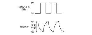
- FIG. 2 is a diagram showing an example of an applied pulse waveform and a measured voltage waveform.
- the pulse waveform applied from the voltage output unit to the measurement point A has a high-side potential of 5 V and a low-side potential of 0 V.
- the earth leakage determination unit 11c identifies the upper peak value Vp1 and the lower peak value Vp2 of the voltage waveform measured during the period when the pulse voltage is applied to the measurement point A, and sets the upper peak value Vp1 and the lower peak value Vp2. The presence or absence of electric leakage is determined based on the peak value defined by the difference between.
- the diagnosis unit 11d diagnoses whether the coupling capacitor Cc is normal or not based on the voltage at the measurement point A measured by the voltage measurement unit 11b. Specifically, in a state where a pulse voltage is applied from the voltage output unit to the measurement point A, the diagnostic unit 11d turns on (closes) the positive main relay MRp and turns off (open) the positive main relay MRp. The coupling capacitor Cc is diagnosed based on the amount of change in the measured voltage before and after the front and rear, before and after the negative side main relay MRm is turned on, or before and after the negative side main relay MRm is turned off.
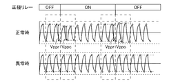
- FIG. 3 is a diagram showing an example of the measurement waveform at the time of failure diagnosis of the coupling capacitor Cc according to the comparative example.
- FIG. 3 shows an example of diagnosing the coupling capacitor Cc based on the amount of change in the measured voltage before and after the positive main relay MRp is turned on and before and after the positive main relay MRp is turned off.
- the diagnosis unit 11d is a coupling capacitor when the amount of decrease of the peak peak value Vppc of the measured voltage immediately after the positive side main relay MRp is turned on from the peak peak value Vppr (specified value) of the measured voltage immediately before the turning is equal to or less than the specified value. Cc is judged to be normal, and when it is not less than the specified value, it is judged to be abnormal. If the coupling capacitor Cc is normally connected to the vehicle side, a change in the leakage state on the vehicle side appears as a decrease in the measurement waveform as the positive main relay MRp is turned on. When the coupling capacitor Cc is abnormal, this decrease in the measured waveform does not appear.
- the diagnostic unit 11d may diagnose the coupling capacitor Cc when the positive main relay MRp is off.
- the diagnostic unit 11d is a coupling capacitor when the amount of increase in the peak peak value Vppo of the measured voltage immediately after the positive main relay MRp is turned off from the peak peak value Vppr (reference value) of the measured voltage immediately before the off is equal to or greater than the specified value.
- Vppr reference value
- Cc is judged to be normal, and when it is not equal to or higher than the specified value, it is judged to be abnormal. If the coupling capacitor Cc is normally connected to the vehicle side, a change in the leakage state on the vehicle side appears as an increase in the measurement waveform as the positive main relay MRp is turned off. When the coupling capacitor Cc is abnormal, this increase in the measured waveform does not appear.
- the diagnostic unit 11d may determine that the coupling capacitor Cc is normal when it detects fluctuations equal to or greater than the respective specified values both when the positive main relay MRp is on and when it is off.
- the coupling capacitor Cc was diagnosed based on the fluctuation of the measured voltage of the peak peak value when the positive side main relay MRp was turned on or off, but when the negative side main relay MRm was turned on or off.
- the coupling capacitor Cc may be diagnosed based on the fluctuation of the peak value of the measured voltage.
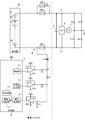
- FIG. 4 is a diagram for explaining the configuration of the power supply system 5 including the earth leakage detection device 10 according to the embodiment.
- the third resistor R3 and the third operational amplifier OP3 are added.
- the control unit 11 further includes a constant voltage output unit 11e.
- the constant voltage output unit 11e can output at least one fixed voltage of the first reference voltage (5V in the present embodiment) and the second reference voltage (0V in the present embodiment).
- the oscillation unit 11a and the first operational amplifier OP1 form the first voltage output unit
- the constant voltage output unit 11e and the third operational amplifier OP3 form the second voltage output unit
- the first voltage output unit is also configured to be able to output at least one fixed voltage of the first reference voltage and the second reference voltage.
- the second resistor R2 and the third resistor R3 are connected in series between the connection point A between the coupling capacitor Cc and the first resistor R1 and the second voltage output unit. More specifically, the constant voltage output from the constant voltage output unit 11e is input to the non-inverting input terminal of the third operational amplifier OP3. The output terminal of the third operational amplifier OP3 is connected to the third resistor R3. The inverting input terminal and the output terminal of the third operational amplifier OP3 are connected. The third operational amplifier OP3 also functions as a voltage follower having an amplification factor of 1 and performing only impedance conversion.
- the voltage dividing point voltage of the second resistor R2 and the third resistor R3 is input to the non-inverting input terminal of the second operational amplifier OP2. That is, the voltage measuring unit 11b measures the voltage at the measuring point A with the compressed voltage by measuring the voltage dividing point voltage of the second resistor R2 and the third resistor R3.
- the earth leakage determination unit 11c calculates the earth leakage resistance value with reference to the earth leakage resistance conversion table based on the voltage amplitude value measured by the voltage measurement unit 11b, and the earth leakage between the current path of the electricity storage unit 20 and the chassis ground. Judge the presence or absence of.
- the period during which the voltage at the measurement point A deviates from the measurement range (0 to 5 V in the present embodiment) can be reduced by dividing the voltage at the measurement point A for measurement. That is, it is possible to reduce the period during which the leakage determination cannot be performed.
- the diagnostic unit 11d is measured by the voltage measuring unit 11b during the on-sequence of the positive side main relay MRp, the negative side main relay MR, and the precharge relay MRpp in a state where a fixed voltage is output from the first voltage output unit. It is diagnosed whether or not the coupling capacitor Cc is normal based on the voltage. Specifically, the diagnostic unit 11d determines that the coupling capacitor Cc is normal when the fluctuation range of the voltage measured during the on-sequence exceeds the specified value, and determines that the coupling capacitor Cc is abnormal when it is below the specified value. judge.
- the specified value is set based on the data obtained by experiments and simulations by the designer.
- the diagnosis unit 11d may diagnose the coupling capacitor Cc when the positive side main relay MRp, the negative side main relay MR, and the precharge relay MRpp are first turned on after the vehicle is started (key-on). In that case, the first voltage output unit outputs a fixed voltage from the first voltage output unit after the vehicle is started.
- An ECU (Electronic Control Unit) (not shown) on the vehicle side starts an on-sequence of the positive side main relay MRp, the negative side main relay MRm, and the precharge relay MRpp after a lapse of a predetermined time from the start of the vehicle.
- the diagnosis unit 11d diagnoses the coupling capacitor Cc during the on-sequence. After the end of the on-sequence, the first voltage output unit switches the output voltage from the fixed voltage to the pulse voltage, and the leakage determination unit 11c starts monitoring the leakage.
- FIG. 5 is a diagram showing an example of a measurement waveform at the time of failure diagnosis of the coupling capacitor Cc according to the embodiment.
- the first voltage output unit outputs a fixed voltage after the vehicle is started.
- the resistance value of the first resistor R1 is 200 k ⁇
- the resistance value of the second resistor R2 is 1000 k ⁇
- the resistance value of the third resistor R3 is 1000 k ⁇ .
- the fixed voltage measured by the voltage measuring unit 11b is about 2.27V as shown in the following (Equation 1).
- the fixed voltage measured by the voltage measurement unit 11b is about 2. It becomes 73V.
- the ECU on the vehicle side starts the on-sequence of the positive side main relay MRp, the negative side main relay MR, and the precharge relay MRpp after several hundred ms have elapsed from the start of the vehicle.
- the elapsed time t1 is a time for eliminating the influence of the dullness of the measurement waveform due to the smoothing capacitor C1, and is a time until the measurement waveform stabilizes.
- the on-sequence period t2 is set to several hundred ms, and during the on-sequence period t2, the ECU on the vehicle side is the negative side main relay MRm, the precharge relay MRpp, and the positive side main relay MRp. Turn on in order.
- the precharge relay is connected to the negative electrode side
- the ECU turns on in the order of the positive side main relay MRp, the precharge relay, and the negative side main relay MRm.
- the diagnostic unit 11d determines that the coupling capacitor Cc is normal when the fluctuation width ⁇ V of the measured voltage during the on-sequence period t2 exceeds the specified value, and determines that the coupling capacitor Cc is abnormal when it is equal to or less than the specified value.
- the fluctuation width ⁇ V is defined by the difference between the maximum value and the minimum value of the measured voltage during the on-sequence period t2.
- the failure diagnosis of the coupling capacitor Cc is performed based on the fluctuation width ⁇ V of the measured voltage during the on-sequence period t2 in the state where the fixed voltage is applied. As a result, failure diagnosis of the coupling capacitor Cc can be performed quickly and with high accuracy.
- the fixed voltage can be measured in the vicinity of the middle of the measurement range. .. Therefore, even if the measured voltage rises or falls, the fluctuation can be measured with high accuracy.
- the circuit configuration according to the comparative example shown in FIG. 1 it is difficult to detect a decrease in the measured voltage when a fixed voltage of 0 V is applied, and when a fixed voltage of 5 V is applied, it is difficult. It is difficult to detect an increase in the measured voltage.
- the value can be measured in a cycle of several tens of ms or less, so it is possible to quickly determine the presence or absence of voltage fluctuation exceeding the specified value. Even if the initial stabilization time t1 is included, the diagnosis of the coupling capacitor Cc can be completed in 1 s or less.
- the voltage output unit outputs a fixed voltage set to a value near the center of the measurement range of the voltage measurement unit 11b, and the diagnosis unit 11d is measured during the contactor on-sequence period. It may be determined whether or not the coupling capacitor Cc is normal based on the voltage.
- the value near the center of the measurement range of the voltage measuring unit 11b may be a value set within the range of ⁇ 1 V of the center voltage of the measurement range. For example, when the measurement range is 0 to 5V, the fixed voltage is set to a value within the range of 1.5 to 3.5V.
- the fixed voltage value may be set outside the range of ⁇ 1 V of the center voltage of the measurement range as long as the measurement voltage is suppressed from sticking to the upper limit or the lower limit of the measurement range due to vertical fluctuations. .. Even with the above method, the same effect as that of the above embodiment can be obtained.
- the failure diagnosis of the coupling capacitor Cc may be performed after the vehicle is parked.
- the contactor since there is time to spare, the contactor may be turned on / off a plurality of times, and the final diagnosis may be made based on the determination results of the plurality of times.
- the precharge relay MRpp and the precharge resistor Rp are connected in parallel with the positive main relay MRp, but when the load is small, the precharge relay MRpp and the precharge resistor Rp are omitted. Is also possible.
- the leakage determination unit 11c can specify the peak peak value from the voltage waveform at the measurement point A and determine the presence or absence of leakage in the same manner as in the above embodiment.
- the earth leakage detection device 10 can be applied to applications other than in-vehicle applications.
- the load may be any load as long as the power storage unit 20 and the load receiving power from the power storage unit 20 are insulated from the ground.
- it may be a load used in a railroad vehicle.
- the embodiment may be specified by the following items.
- Leakage determination unit (11c) that determines the presence or absence of leakage between In a state where a fixed voltage is output from the voltage output unit (11a, OP1), when the switch (MRp, MRm, MRpp) is turned on, the voltage measured by the voltage measurement unit (11b) is also applied.
- Leakage determination unit (11c) that determines the presence or absence of leakage between The switch (MRp, MRm, MRpp) is turned on while a fixed voltage set to a value near the center of the measurement range of the voltage measuring unit (11b) is output from the voltage output unit (11a, OP1).
- the diagnostic unit (11d) determines whether or not the coupling capacitor (Cc) is normal based on the voltage measured by the voltage measuring unit (11b).
- An earth leakage detection device comprising. According to this, the failure diagnosis of the coupling capacitor (Cc) can be performed quickly and with high accuracy.
- the diagnostic unit (11d) is the coupling capacitor when the fluctuation range of the voltage measured by the voltage measuring unit (11b) is equal to or less than a specified value when the switch (MRp, MRm, MRpp) is turned on.
- the leakage detection device (10) according to item 1 or 2, wherein (Cc) is determined to be abnormal. According to this, the failure diagnosis of the coupling capacitor (Cc) can be performed quickly and with high accuracy.
- the switches are A positive electrode relay (MRp) inserted into the positive wiring to which the positive electrode of the power storage unit (20) and one end of the load (2) are connected, and A negative electrode relay (MRm) inserted into the negative wiring to which the negative electrode of the power storage unit (20) and the other end of the load (2) are connected, and A precharge relay (MRpp) connected in parallel to the positive electrode relay (MRp) or the negative electrode relay (MRm) is included.
- the diagnostic unit (11d) the fluctuation range of the measured voltage in the period from when one of the three relays (MRp, MRm, MRpp) is turned on until when three are turned on is the specified value.
- a power storage unit (20) that is mounted in a state of being insulated from the chassis ground of the vehicle and supplies electric power to the load (2) in the vehicle.
- the leakage detection device (10) according to any one of items 1 to 4, and the leakage detection device (10).
- a vehicle power supply system (5) including an electric leakage detection device (10) capable of quickly and accurately diagnosing a failure of the coupling capacitor (Cc).
- the diagnostic unit (11d) determines whether or not the coupling capacitor (Cc) is normal when the switches (MRp, MRm, MRpp) are first turned on after the vehicle is started.
- the vehicle power supply system (5) according to the feature item 5. According to this, the failure diagnosis of the coupling capacitor (Cc) can be performed without setting a special diagnosis period.
Landscapes
- Engineering & Computer Science (AREA)
- Power Engineering (AREA)
- General Physics & Mathematics (AREA)
- Physics & Mathematics (AREA)
- Sustainable Development (AREA)
- Life Sciences & Earth Sciences (AREA)
- Sustainable Energy (AREA)
- Transportation (AREA)
- Mechanical Engineering (AREA)
- Chemical & Material Sciences (AREA)
- Combustion & Propulsion (AREA)
- Testing Of Short-Circuits, Discontinuities, Leakage, Or Incorrect Line Connections (AREA)
- Electric Propulsion And Braking For Vehicles (AREA)
- Testing Electric Properties And Detecting Electric Faults (AREA)
Abstract
Description
図1は、比較例に係る漏電検出装置10を備える電源システム5の構成を説明するための図である。電源システム5は電動車両に搭載される。電源システム5は電動車両内において、補機電池(通常、12V出力の鉛電池が使用される)と別に設けられる。電源システム5は、高電圧の蓄電部20、及び漏電検出装置10を含む。蓄電部20は、直列接続された複数のセルE1-Enを含む。セルには、リチウムイオン電池セル、ニッケル水素電池セル、鉛電池セル、電気二重層キャパシタセル、リチウムイオンキャパシタセル等を用いることができる。以下、本明細書ではリチウムイオン電池セル(公称電圧:3.6-3.7V)を使用する例を想定する。
図4は、実施の形態に係る漏電検出装置10を備える電源システム5の構成を説明するための図である。以下、図1に示した比較例に係る電源システム5の構成との相違点を説明する。実施の形態では第3抵抗R3及び第3オペアンプOP3が追加される。制御部11は、定電圧出力部11eをさらに含む。定電圧出力部11eは、第1基準電圧(本実施の形態では5V)と第2基準電圧(本実施の形態では0V)の少なくとも一方の固定電圧を出力することができる。
5×((200+1000)/(200+1000+1000))≒2.73 ・・・
(式2)
車両のシャーシアースと絶縁された状態で搭載され、前記車両内の負荷(2)に電力を供給する蓄電部(20)と、前記蓄電部(20)と前記負荷(2)を接続する配線に挿入されるスイッチ(MRp、MRm、MRpp)と、を備える車両に搭載される漏電検出装置(10)であって、
アースと絶縁された状態で、負荷(2)に接続されている蓄電部(20)の電流経路に一端が接続されるカップリングコンデンサ(Cc)と、
周期的に変化する周期電圧を生成して、前記カップリングコンデンサ(Cc)の他端に第1抵抗(R1)を介して印加する電圧出力部(11a、OP1)と、
前記カップリングコンデンサ(Cc)と前記第1抵抗(R1)との間の接続点と、所定の固定電位との間に直列に接続された第2抵抗(R2)および第3抵抗(R3)と、
前記第2抵抗(R2)と前記第3抵抗(R3)との間の分圧点の電圧を測定する電圧測定部(11b)と、
前記電圧出力部(11a、OP1)から前記周期電圧が出力されている状態において、前記電圧測定部(11b)により測定された電圧をもとに、前記蓄電部(20)の電流経路と前記アース間の漏電の有無を判定する漏電判定部(11c)と、
前記電圧出力部(11a、OP1)から固定電圧が出力されている状態において、前記スイッチ(MRp、MRm、MRpp)がターンオンされるときに、前記電圧測定部(11b)により測定される電圧をもとに、前記カップリングコンデンサ(Cc)が正常であるか否かを判定する診断部(11d)と、
を備えることを特徴とする漏電検出装置(10)。
これによれば、カップリングコンデンサ(Cc)の故障診断を迅速かつ高精度に行うことができる。
[項目2]
車両のシャーシアースと絶縁された状態で搭載され、前記車両内の負荷(2)に電力を供給する蓄電部(20)と、前記蓄電部(20)と前記負荷(2)を接続する配線に挿入されるスイッチ(MRp、MRm、MRpp)と、を備える車両に搭載される漏電検出装置(10)であって、
周期的に変化する周期電圧を生成して、前記カップリングコンデンサ(Cc)の他端に抵抗(R1)を介して印加する電圧出力部(11a、OP1)と、
前記カップリングコンデンサ(Cc)と前記抵抗(R1)との間の接続点の電圧を測定する電圧測定部(11b)と、
前記電圧出力部(11a、OP1)から前記周期電圧が出力されている状態において、前記電圧測定部(11b)により測定された電圧をもとに、前記蓄電部(20)の電流経路と前記アース間の漏電の有無を判定する漏電判定部(11c)と、
前記電圧出力部(11a、OP1)から前記電圧測定部(11b)の測定レンジの中心付近の値に設定された固定電圧が出力されている状態において、前記スイッチ(MRp、MRm、MRpp)がターンオンされるときに、前記電圧測定部(11b)により測定される電圧をもとに、前記カップリングコンデンサ(Cc)が正常であるか否かを判定する診断部(11d)と、
を備えることを特徴とする漏電検出装置。
これによれば、カップリングコンデンサ(Cc)の故障診断を迅速かつ高精度に行うことができる。
[項目3]
前記診断部(11d)は、前記スイッチ(MRp、MRm、MRpp)がターンオンされるときに、前記電圧測定部(11b)により測定された電圧の変動幅が規定値以下の場合、前記カップリングコンデンサ(Cc)を異常と判定することを特徴とする項目1または2に記載の漏電検出装置(10)。
これによれば、カップリングコンデンサ(Cc)の故障診断を迅速かつ高精度に行うことができる。
[項目4]
前記スイッチ(MRp、MRm、MRpp)は、
前記蓄電部(20)の正極と前記負荷(2)の一端が接続されるプラス配線に挿入される正極リレー(MRp)と、
前記蓄電部(20)の負極と前記負荷(2)の他端が接続されるマイナス配線に挿入される負極リレー(MRm)と、
前記正極リレー(MRp)又は前記負極リレー(MRm)に並列に接続されたプリチャージリレー(MRpp)と、を含み、
前記診断部(11d)は、前記3つのリレー(MRp、MRm、MRpp)の1つがターンオンされてから、3つがオン状態になるまでの期間における前記測定された電圧の変動幅が、前記規定値以下の場合、前記カップリングコンデンサ(Cc)を異常と判定することを特徴とする項目3に記載の漏電検出装置(10)。
これによれば、プリチャージリレーを含むコンタクタで車両側の負荷(2)と接続される構成において、カップリングコンデンサ(Cc)の故障診断を迅速かつ高精度に行うことができる。
[項目5]
車両のシャーシアースと絶縁された状態で搭載され、前記車両内の負荷(2)に電力を供給する蓄電部(20)と、
項目1から4のいずれか1項に記載の漏電検出装置(10)と、
を備えることを特徴とする車両用電源システム(5)。
これによれば、カップリングコンデンサ(Cc)の故障診断を迅速かつ高精度に行うことができる漏電検出装置(10)を備える車両用電源システム(5)を実現することができる。
[項目6]
前記診断部(11d)は、前記車両の起動後、最初に前記スイッチ(MRp、MRm、MRpp)がターンオンされるとき、前記カップリングコンデンサ(Cc)が正常であるか否かを判定することを特徴とする項目5に記載の車両用電源システム(5)。
これによれば、特別な診断期間を設定せずとも、カップリングコンデンサ(Cc)の故障診断を行うことができる。
11a 発振部、 11b 電圧測定部、 11c 漏電判定部、 11d 診断部、
11e 定電圧出力部、 Cc カップリングコンデンサ、 R1 第1抵抗、 R2
第2抵抗、 R3 第3抵抗、 C1 平滑用コンデンサ、 OP1 第1オペアンプ、 OP2 第2オペアンプ、 OP3 第3オペアンプ。
Claims (6)
- 車両のシャーシアースと絶縁された状態で搭載され、前記車両内の負荷に電力を供給する蓄電部と、前記蓄電部と前記負荷を接続する配線に挿入されるスイッチと、を備える車両に搭載される漏電検出装置であって、
アースと絶縁された状態で、負荷に接続されている蓄電部の電流経路に一端が接続されるカップリングコンデンサと、
周期的に変化する周期電圧を生成して、前記カップリングコンデンサの他端に第1抵抗を介して印加する電圧出力部と、
前記カップリングコンデンサと前記第1抵抗との間の接続点と、所定の固定電位との間に直列に接続された第2抵抗および第3抵抗と、
前記第2抵抗と前記第3抵抗との間の分圧点の電圧を測定する電圧測定部と、
前記電圧出力部から前記周期電圧が出力されている状態において、前記電圧測定部により測定された電圧をもとに、前記蓄電部の電流経路と前記アース間の漏電の有無を判定する漏電判定部と、
前記電圧出力部から固定電圧が出力されている状態において、前記スイッチがターンオンされるときに、前記電圧測定部により測定される電圧をもとに、前記カップリングコンデンサが正常であるか否かを判定する診断部と、
を備えることを特徴とする漏電検出装置。 - 車両のシャーシアースと絶縁された状態で搭載され、前記車両内の負荷に電力を供給する蓄電部と、前記蓄電部と前記負荷を接続する配線に挿入されるスイッチと、を備える車両に搭載される漏電検出装置であって、
アースと絶縁された状態で、負荷に接続されている蓄電部の電流経路に一端が接続されるカップリングコンデンサと、
周期的に変化する周期電圧を生成して、前記カップリングコンデンサの他端に抵抗を介して印加する電圧出力部と、
前記カップリングコンデンサと前記抵抗との間の接続点の電圧を測定する電圧測定部と、
前記電圧出力部から前記周期電圧が出力されている状態において、前記電圧測定部により測定された電圧をもとに、前記蓄電部の電流経路と前記アース間の漏電の有無を判定する漏電判定部と、
前記電圧出力部から前記電圧測定部の測定レンジの中心付近の値に設定された固定電圧が出力されている状態において、前記スイッチがターンオンされるときに、前記電圧測定部により測定される電圧をもとに、前記カップリングコンデンサが正常であるか否かを判定する診断部と、
を備えることを特徴とする漏電検出装置。 - 前記診断部は、前記スイッチがターンオンされるときに、前記電圧測定部により測定された電圧の変動幅が規定値以下の場合、前記カップリングコンデンサを異常と判定することを特徴とする請求項1または2に記載の漏電検出装置。
- 前記スイッチは、
前記蓄電部の正極と前記負荷の一端が接続されるプラス配線に挿入される正極リレーと、
前記蓄電部の負極と前記負荷の他端が接続されるマイナス配線に挿入される負極リレーと、
前記正極リレー又は前記負極リレーに並列に接続されたプリチャージリレーと、を含み、
前記診断部は、前記3つのリレーの1つがターンオンされてから、3つがオン状態になるまでの期間における前記測定された電圧の変動幅が、前記規定値以下の場合、前記カップリングコンデンサを異常と判定することを特徴とする請求項3に記載の漏電検出装置。 - 車両のシャーシアースと絶縁された状態で搭載され、前記車両内の負荷に電力を供給する蓄電部と、
請求項1から4のいずれか1項に記載の漏電検出装置と、
を備えることを特徴とする車両用電源システム。 - 前記診断部は、前記車両の起動後、最初に前記スイッチがターンオンされるとき、前記カップリングコンデンサが正常であるか否かを判定することを特徴とする請求項5に記載の車両用電源システム。
Priority Applications (4)
| Application Number | Priority Date | Filing Date | Title |
|---|---|---|---|
| JP2021561160A JP7542554B2 (ja) | 2019-11-26 | 2020-08-18 | 漏電検出装置、車両用電源システム |
| EP20894330.8A EP4068544B1 (en) | 2019-11-26 | 2020-08-18 | Earth leakage detection device and vehicle power supply system |
| CN202080081632.9A CN114729972B (zh) | 2019-11-26 | 2020-08-18 | 漏电检测装置、车辆用电源系统 |
| US17/756,053 US12117502B2 (en) | 2019-11-26 | 2020-08-18 | Earth leakage detection device and vehicle power supply system |
Applications Claiming Priority (2)
| Application Number | Priority Date | Filing Date | Title |
|---|---|---|---|
| JP2019213255 | 2019-11-26 | ||
| JP2019-213255 | 2019-11-26 |
Publications (1)
| Publication Number | Publication Date |
|---|---|
| WO2021106284A1 true WO2021106284A1 (ja) | 2021-06-03 |
Family
ID=76128848
Family Applications (1)
| Application Number | Title | Priority Date | Filing Date |
|---|---|---|---|
| PCT/JP2020/031045 Ceased WO2021106284A1 (ja) | 2019-11-26 | 2020-08-18 | 漏電検出装置、車両用電源システム |
Country Status (5)
| Country | Link |
|---|---|
| US (1) | US12117502B2 (ja) |
| EP (1) | EP4068544B1 (ja) |
| JP (1) | JP7542554B2 (ja) |
| CN (1) | CN114729972B (ja) |
| WO (1) | WO2021106284A1 (ja) |
Cited By (1)
| Publication number | Priority date | Publication date | Assignee | Title |
|---|---|---|---|---|
| CN117200132A (zh) * | 2022-05-31 | 2023-12-08 | 比亚迪股份有限公司 | 一种轨交车辆及其的漏电保护方法和系统 |
Families Citing this family (4)
| Publication number | Priority date | Publication date | Assignee | Title |
|---|---|---|---|---|
| WO2020262084A1 (ja) * | 2019-06-28 | 2020-12-30 | 三洋電機株式会社 | 漏電検出装置、車両用電源システム |
| JP7534387B2 (ja) | 2020-03-30 | 2024-08-14 | 三洋電機株式会社 | 漏電検出装置、車両用電源システム |
| DE102022202988A1 (de) * | 2022-03-25 | 2023-09-28 | Ellenberger & Poensgen Gmbh | Hauptschalter eines Bordnetzes eines Fahrzeugs |
| CN116699344A (zh) * | 2023-05-19 | 2023-09-05 | 深圳麦格米特电气股份有限公司 | 一种绝缘检测电路和绝缘检测方法 |
Citations (9)
| Publication number | Priority date | Publication date | Assignee | Title |
|---|---|---|---|---|
| JPH03209179A (ja) * | 1990-01-11 | 1991-09-12 | Rohm Co Ltd | コンデンサのリーク検査器 |
| JP2004053367A (ja) | 2002-07-18 | 2004-02-19 | Nissan Motor Co Ltd | 地絡検知回路の故障診断装置 |
| JP2007163291A (ja) * | 2005-12-14 | 2007-06-28 | Denso Corp | 車両用対地絶縁回路の絶縁性能診断装置 |
| JP2010151595A (ja) * | 2008-12-25 | 2010-07-08 | Omron Corp | 検知装置および方法 |
| WO2012029214A1 (ja) * | 2010-08-31 | 2012-03-08 | パナソニック株式会社 | 車両用絶縁抵抗検出装置 |
| JP2013195136A (ja) * | 2012-03-16 | 2013-09-30 | Mitsubishi Electric Corp | 車載高電圧機器の漏電抵抗検出装置およびその漏電抵抗検出方法 |
| JP2016024155A (ja) * | 2014-07-24 | 2016-02-08 | パナソニックIpマネジメント株式会社 | 異常検出装置 |
| JP2017142269A (ja) * | 2013-11-22 | 2017-08-17 | 三菱電機株式会社 | 絶縁検出器及び電気機器 |
| WO2019176173A1 (ja) * | 2018-03-15 | 2019-09-19 | 三洋電機株式会社 | 漏電検出回路、車両用電源システム |
Family Cites Families (7)
| Publication number | Priority date | Publication date | Assignee | Title |
|---|---|---|---|---|
| JP4198019B2 (ja) | 2003-10-07 | 2008-12-17 | 矢崎総業株式会社 | 状態検出方法及び絶縁抵抗低下検出器 |
| JP4834393B2 (ja) | 2005-12-09 | 2011-12-14 | 矢崎総業株式会社 | 状態検出方法及び絶縁抵抗低下検出器 |
| JP4974814B2 (ja) | 2007-08-29 | 2012-07-11 | カルソニックカンセイ株式会社 | 車両用地絡検出回路 |
| JP2009085830A (ja) | 2007-10-01 | 2009-04-23 | Toyota Industries Corp | 産業車両における絶縁抵抗低下検出装置 |
| JP5533864B2 (ja) | 2009-06-12 | 2014-06-25 | 日産自動車株式会社 | 地絡検出器の接続診断装置 |
| JP5615342B2 (ja) | 2012-10-19 | 2014-10-29 | オムロンオートモーティブエレクトロニクス株式会社 | 漏電検知装置 |
| JP2015087217A (ja) * | 2013-10-30 | 2015-05-07 | オムロンオートモーティブエレクトロニクス株式会社 | 漏電検出装置 |
-
2020
- 2020-08-18 EP EP20894330.8A patent/EP4068544B1/en active Active
- 2020-08-18 US US17/756,053 patent/US12117502B2/en active Active
- 2020-08-18 JP JP2021561160A patent/JP7542554B2/ja active Active
- 2020-08-18 WO PCT/JP2020/031045 patent/WO2021106284A1/ja not_active Ceased
- 2020-08-18 CN CN202080081632.9A patent/CN114729972B/zh active Active
Patent Citations (9)
| Publication number | Priority date | Publication date | Assignee | Title |
|---|---|---|---|---|
| JPH03209179A (ja) * | 1990-01-11 | 1991-09-12 | Rohm Co Ltd | コンデンサのリーク検査器 |
| JP2004053367A (ja) | 2002-07-18 | 2004-02-19 | Nissan Motor Co Ltd | 地絡検知回路の故障診断装置 |
| JP2007163291A (ja) * | 2005-12-14 | 2007-06-28 | Denso Corp | 車両用対地絶縁回路の絶縁性能診断装置 |
| JP2010151595A (ja) * | 2008-12-25 | 2010-07-08 | Omron Corp | 検知装置および方法 |
| WO2012029214A1 (ja) * | 2010-08-31 | 2012-03-08 | パナソニック株式会社 | 車両用絶縁抵抗検出装置 |
| JP2013195136A (ja) * | 2012-03-16 | 2013-09-30 | Mitsubishi Electric Corp | 車載高電圧機器の漏電抵抗検出装置およびその漏電抵抗検出方法 |
| JP2017142269A (ja) * | 2013-11-22 | 2017-08-17 | 三菱電機株式会社 | 絶縁検出器及び電気機器 |
| JP2016024155A (ja) * | 2014-07-24 | 2016-02-08 | パナソニックIpマネジメント株式会社 | 異常検出装置 |
| WO2019176173A1 (ja) * | 2018-03-15 | 2019-09-19 | 三洋電機株式会社 | 漏電検出回路、車両用電源システム |
Non-Patent Citations (1)
| Title |
|---|
| See also references of EP4068544A4 |
Cited By (1)
| Publication number | Priority date | Publication date | Assignee | Title |
|---|---|---|---|---|
| CN117200132A (zh) * | 2022-05-31 | 2023-12-08 | 比亚迪股份有限公司 | 一种轨交车辆及其的漏电保护方法和系统 |
Also Published As
| Publication number | Publication date |
|---|---|
| EP4068544B1 (en) | 2025-10-08 |
| JP7542554B2 (ja) | 2024-08-30 |
| CN114729972A (zh) | 2022-07-08 |
| EP4068544A1 (en) | 2022-10-05 |
| JPWO2021106284A1 (ja) | 2021-06-03 |
| US20220404432A1 (en) | 2022-12-22 |
| US12117502B2 (en) | 2024-10-15 |
| EP4068544A4 (en) | 2023-01-18 |
| CN114729972B (zh) | 2025-11-14 |
Similar Documents
| Publication | Publication Date | Title |
|---|---|---|
| JP7542554B2 (ja) | 漏電検出装置、車両用電源システム | |
| JP7431212B2 (ja) | 漏電検出装置、車両用電源システム | |
| JP7554191B2 (ja) | 漏電検出装置、車両用電源システム | |
| CN113841059B (zh) | 漏电检测装置、车辆用电源系统 | |
| JP6414520B2 (ja) | 検査システム | |
| CN103592559A (zh) | 对地短路检测电路、电源装置 | |
| JPWO2020170557A1 (ja) | 漏電検出装置、車両用電源システム | |
| JP7608359B2 (ja) | 漏電検出装置、車両用電源システム | |
| JP2020134295A (ja) | 漏電検出装置、車両用電源システム | |
| JP7431324B2 (ja) | 検出回路および集積回路 | |
| JP7534387B2 (ja) | 漏電検出装置、車両用電源システム | |
| JP7458397B2 (ja) | 漏電検出装置、車両用電源システム |
Legal Events
| Date | Code | Title | Description |
|---|---|---|---|
| 121 | Ep: the epo has been informed by wipo that ep was designated in this application |
Ref document number: 20894330 Country of ref document: EP Kind code of ref document: A1 |
|
| ENP | Entry into the national phase |
Ref document number: 2021561160 Country of ref document: JP Kind code of ref document: A |
|
| WWE | Wipo information: entry into national phase |
Ref document number: 202080081632.9 Country of ref document: CN |
|
| NENP | Non-entry into the national phase |
Ref country code: DE |
|
| ENP | Entry into the national phase |
Ref document number: 2020894330 Country of ref document: EP Effective date: 20220627 |
|
| WWG | Wipo information: grant in national office |
Ref document number: 2020894330 Country of ref document: EP |