WO2021106545A1 - 充填包装機およびこれに用いられる横シール装置 - Google Patents
充填包装機およびこれに用いられる横シール装置 Download PDFInfo
- Publication number
- WO2021106545A1 WO2021106545A1 PCT/JP2020/041847 JP2020041847W WO2021106545A1 WO 2021106545 A1 WO2021106545 A1 WO 2021106545A1 JP 2020041847 W JP2020041847 W JP 2020041847W WO 2021106545 A1 WO2021106545 A1 WO 2021106545A1
- Authority
- WO
- WIPO (PCT)
- Prior art keywords
- sealing
- packaging material
- groove
- filling
- tape
- Prior art date
- Legal status (The legal status is an assumption and is not a legal conclusion. Google has not performed a legal analysis and makes no representation as to the accuracy of the status listed.)
- Ceased
Links
Images



Classifications
-
- B—PERFORMING OPERATIONS; TRANSPORTING
- B65—CONVEYING; PACKING; STORING; HANDLING THIN OR FILAMENTARY MATERIAL
- B65B—MACHINES, APPARATUS OR DEVICES FOR, OR METHODS OF, PACKAGING ARTICLES OR MATERIALS; UNPACKING
- B65B51/00—Devices for, or methods of, sealing or securing package folds or closures; Devices for gathering or twisting wrappers, or necks of bags
- B65B51/10—Applying or generating heat or pressure or combinations thereof
- B65B51/22—Applying or generating heat or pressure or combinations thereof by friction or ultrasonic or high-frequency electrical means
- B65B51/225—Applying or generating heat or pressure or combinations thereof by friction or ultrasonic or high-frequency electrical means by ultrasonic welding
-
- B—PERFORMING OPERATIONS; TRANSPORTING
- B29—WORKING OF PLASTICS; WORKING OF SUBSTANCES IN A PLASTIC STATE IN GENERAL
- B29C—SHAPING OR JOINING OF PLASTICS; SHAPING OF MATERIAL IN A PLASTIC STATE, NOT OTHERWISE PROVIDED FOR; AFTER-TREATMENT OF THE SHAPED PRODUCTS, e.g. REPAIRING
- B29C65/00—Joining or sealing of preformed parts, e.g. welding of plastics materials; Apparatus therefor
- B29C65/02—Joining or sealing of preformed parts, e.g. welding of plastics materials; Apparatus therefor by heating, with or without pressure
- B29C65/08—Joining or sealing of preformed parts, e.g. welding of plastics materials; Apparatus therefor by heating, with or without pressure using ultrasonic vibrations
-
- B—PERFORMING OPERATIONS; TRANSPORTING
- B29—WORKING OF PLASTICS; WORKING OF SUBSTANCES IN A PLASTIC STATE IN GENERAL
- B29C—SHAPING OR JOINING OF PLASTICS; SHAPING OF MATERIAL IN A PLASTIC STATE, NOT OTHERWISE PROVIDED FOR; AFTER-TREATMENT OF THE SHAPED PRODUCTS, e.g. REPAIRING
- B29C65/00—Joining or sealing of preformed parts, e.g. welding of plastics materials; Apparatus therefor
- B29C65/48—Joining or sealing of preformed parts, e.g. welding of plastics materials; Apparatus therefor using adhesives, i.e. using supplementary joining material; solvent bonding
- B29C65/4805—Joining or sealing of preformed parts, e.g. welding of plastics materials; Apparatus therefor using adhesives, i.e. using supplementary joining material; solvent bonding characterised by the type of adhesives
- B29C65/481—Non-reactive adhesives, e.g. physically hardening adhesives
- B29C65/4815—Hot melt adhesives, e.g. thermoplastic adhesives
-
- B—PERFORMING OPERATIONS; TRANSPORTING
- B29—WORKING OF PLASTICS; WORKING OF SUBSTANCES IN A PLASTIC STATE IN GENERAL
- B29C—SHAPING OR JOINING OF PLASTICS; SHAPING OF MATERIAL IN A PLASTIC STATE, NOT OTHERWISE PROVIDED FOR; AFTER-TREATMENT OF THE SHAPED PRODUCTS, e.g. REPAIRING
- B29C65/00—Joining or sealing of preformed parts, e.g. welding of plastics materials; Apparatus therefor
- B29C65/48—Joining or sealing of preformed parts, e.g. welding of plastics materials; Apparatus therefor using adhesives, i.e. using supplementary joining material; solvent bonding
- B29C65/50—Joining or sealing of preformed parts, e.g. welding of plastics materials; Apparatus therefor using adhesives, i.e. using supplementary joining material; solvent bonding using adhesive tape, e.g. thermoplastic tape; using threads or the like
- B29C65/5042—Joining or sealing of preformed parts, e.g. welding of plastics materials; Apparatus therefor using adhesives, i.e. using supplementary joining material; solvent bonding using adhesive tape, e.g. thermoplastic tape; using threads or the like covering both elements to be joined
-
- B—PERFORMING OPERATIONS; TRANSPORTING
- B29—WORKING OF PLASTICS; WORKING OF SUBSTANCES IN A PLASTIC STATE IN GENERAL
- B29C—SHAPING OR JOINING OF PLASTICS; SHAPING OF MATERIAL IN A PLASTIC STATE, NOT OTHERWISE PROVIDED FOR; AFTER-TREATMENT OF THE SHAPED PRODUCTS, e.g. REPAIRING
- B29C65/00—Joining or sealing of preformed parts, e.g. welding of plastics materials; Apparatus therefor
- B29C65/48—Joining or sealing of preformed parts, e.g. welding of plastics materials; Apparatus therefor using adhesives, i.e. using supplementary joining material; solvent bonding
- B29C65/50—Joining or sealing of preformed parts, e.g. welding of plastics materials; Apparatus therefor using adhesives, i.e. using supplementary joining material; solvent bonding using adhesive tape, e.g. thermoplastic tape; using threads or the like
- B29C65/5057—Joining or sealing of preformed parts, e.g. welding of plastics materials; Apparatus therefor using adhesives, i.e. using supplementary joining material; solvent bonding using adhesive tape, e.g. thermoplastic tape; using threads or the like positioned between the surfaces to be joined
-
- B—PERFORMING OPERATIONS; TRANSPORTING
- B29—WORKING OF PLASTICS; WORKING OF SUBSTANCES IN A PLASTIC STATE IN GENERAL
- B29C—SHAPING OR JOINING OF PLASTICS; SHAPING OF MATERIAL IN A PLASTIC STATE, NOT OTHERWISE PROVIDED FOR; AFTER-TREATMENT OF THE SHAPED PRODUCTS, e.g. REPAIRING
- B29C65/00—Joining or sealing of preformed parts, e.g. welding of plastics materials; Apparatus therefor
- B29C65/74—Joining or sealing of preformed parts, e.g. welding of plastics materials; Apparatus therefor by welding and severing, or by joining and severing, the severing being performed in the area to be joined, next to the area to be joined, in the joint area or next to the joint area
- B29C65/745—Joining or sealing of preformed parts, e.g. welding of plastics materials; Apparatus therefor by welding and severing, or by joining and severing, the severing being performed in the area to be joined, next to the area to be joined, in the joint area or next to the joint area using a single unit having both a severing tool and a welding tool
- B29C65/7451—Joining or sealing of preformed parts, e.g. welding of plastics materials; Apparatus therefor by welding and severing, or by joining and severing, the severing being performed in the area to be joined, next to the area to be joined, in the joint area or next to the joint area using a single unit having both a severing tool and a welding tool the severing tool and the welding tool being movable with respect to one-another
-
- B—PERFORMING OPERATIONS; TRANSPORTING
- B29—WORKING OF PLASTICS; WORKING OF SUBSTANCES IN A PLASTIC STATE IN GENERAL
- B29C—SHAPING OR JOINING OF PLASTICS; SHAPING OF MATERIAL IN A PLASTIC STATE, NOT OTHERWISE PROVIDED FOR; AFTER-TREATMENT OF THE SHAPED PRODUCTS, e.g. REPAIRING
- B29C65/00—Joining or sealing of preformed parts, e.g. welding of plastics materials; Apparatus therefor
- B29C65/78—Means for handling the parts to be joined, e.g. for making containers or hollow articles, e.g. means for handling sheets, plates, web-like materials, tubular articles, hollow articles or elements to be joined therewith; Means for discharging the joined articles from the joining apparatus
- B29C65/7858—Means for handling the parts to be joined, e.g. for making containers or hollow articles, e.g. means for handling sheets, plates, web-like materials, tubular articles, hollow articles or elements to be joined therewith; Means for discharging the joined articles from the joining apparatus characterised by the feeding movement of the parts to be joined
- B29C65/7888—Means for handling of moving sheets or webs
- B29C65/7894—Means for handling of moving sheets or webs of continuously moving sheets or webs
-
- B—PERFORMING OPERATIONS; TRANSPORTING
- B29—WORKING OF PLASTICS; WORKING OF SUBSTANCES IN A PLASTIC STATE IN GENERAL
- B29C—SHAPING OR JOINING OF PLASTICS; SHAPING OF MATERIAL IN A PLASTIC STATE, NOT OTHERWISE PROVIDED FOR; AFTER-TREATMENT OF THE SHAPED PRODUCTS, e.g. REPAIRING
- B29C66/00—General aspects of processes or apparatus for joining preformed parts
- B29C66/01—General aspects dealing with the joint area or with the area to be joined
- B29C66/05—Particular design of joint configurations
- B29C66/10—Particular design of joint configurations particular design of the joint cross-sections
- B29C66/11—Joint cross-sections comprising a single joint-segment, i.e. one of the parts to be joined comprising a single joint-segment in the joint cross-section
- B29C66/112—Single lapped joints
- B29C66/1122—Single lap to lap joints, i.e. overlap joints
-
- B—PERFORMING OPERATIONS; TRANSPORTING
- B29—WORKING OF PLASTICS; WORKING OF SUBSTANCES IN A PLASTIC STATE IN GENERAL
- B29C—SHAPING OR JOINING OF PLASTICS; SHAPING OF MATERIAL IN A PLASTIC STATE, NOT OTHERWISE PROVIDED FOR; AFTER-TREATMENT OF THE SHAPED PRODUCTS, e.g. REPAIRING
- B29C66/00—General aspects of processes or apparatus for joining preformed parts
- B29C66/01—General aspects dealing with the joint area or with the area to be joined
- B29C66/05—Particular design of joint configurations
- B29C66/10—Particular design of joint configurations particular design of the joint cross-sections
- B29C66/12—Joint cross-sections combining only two joint-segments; Tongue and groove joints; Tenon and mortise joints; Stepped joint cross-sections
- B29C66/128—Stepped joint cross-sections
- B29C66/1282—Stepped joint cross-sections comprising at least one overlap joint-segment
- B29C66/12821—Stepped joint cross-sections comprising at least one overlap joint-segment comprising at least two overlap joint-segments
- B29C66/12822—Stepped joint cross-sections comprising at least one overlap joint-segment comprising at least two overlap joint-segments comprising at least three overlap joint-segments
-
- B—PERFORMING OPERATIONS; TRANSPORTING
- B29—WORKING OF PLASTICS; WORKING OF SUBSTANCES IN A PLASTIC STATE IN GENERAL
- B29C—SHAPING OR JOINING OF PLASTICS; SHAPING OF MATERIAL IN A PLASTIC STATE, NOT OTHERWISE PROVIDED FOR; AFTER-TREATMENT OF THE SHAPED PRODUCTS, e.g. REPAIRING
- B29C66/00—General aspects of processes or apparatus for joining preformed parts
- B29C66/01—General aspects dealing with the joint area or with the area to be joined
- B29C66/346—Making joints having variable thicknesses in the joint area, e.g. by using jaws having an adapted configuration
-
- B—PERFORMING OPERATIONS; TRANSPORTING
- B29—WORKING OF PLASTICS; WORKING OF SUBSTANCES IN A PLASTIC STATE IN GENERAL
- B29C—SHAPING OR JOINING OF PLASTICS; SHAPING OF MATERIAL IN A PLASTIC STATE, NOT OTHERWISE PROVIDED FOR; AFTER-TREATMENT OF THE SHAPED PRODUCTS, e.g. REPAIRING
- B29C66/00—General aspects of processes or apparatus for joining preformed parts
- B29C66/40—General aspects of joining substantially flat articles, e.g. plates, sheets or web-like materials; Making flat seams in tubular or hollow articles; Joining single elements to substantially flat surfaces
- B29C66/41—Joining substantially flat articles ; Making flat seams in tubular or hollow articles
- B29C66/43—Joining a relatively small portion of the surface of said articles
- B29C66/431—Joining the articles to themselves
- B29C66/4312—Joining the articles to themselves for making flat seams in tubular or hollow articles, e.g. transversal seams
-
- B—PERFORMING OPERATIONS; TRANSPORTING
- B29—WORKING OF PLASTICS; WORKING OF SUBSTANCES IN A PLASTIC STATE IN GENERAL
- B29C—SHAPING OR JOINING OF PLASTICS; SHAPING OF MATERIAL IN A PLASTIC STATE, NOT OTHERWISE PROVIDED FOR; AFTER-TREATMENT OF THE SHAPED PRODUCTS, e.g. REPAIRING
- B29C66/00—General aspects of processes or apparatus for joining preformed parts
- B29C66/40—General aspects of joining substantially flat articles, e.g. plates, sheets or web-like materials; Making flat seams in tubular or hollow articles; Joining single elements to substantially flat surfaces
- B29C66/41—Joining substantially flat articles ; Making flat seams in tubular or hollow articles
- B29C66/43—Joining a relatively small portion of the surface of said articles
- B29C66/432—Joining a relatively small portion of the surface of said articles for making tubular articles or closed loops, e.g. by joining several sheets ; for making hollow articles or hollow preforms
- B29C66/4322—Joining a relatively small portion of the surface of said articles for making tubular articles or closed loops, e.g. by joining several sheets ; for making hollow articles or hollow preforms by joining a single sheet to itself
-
- B—PERFORMING OPERATIONS; TRANSPORTING
- B29—WORKING OF PLASTICS; WORKING OF SUBSTANCES IN A PLASTIC STATE IN GENERAL
- B29C—SHAPING OR JOINING OF PLASTICS; SHAPING OF MATERIAL IN A PLASTIC STATE, NOT OTHERWISE PROVIDED FOR; AFTER-TREATMENT OF THE SHAPED PRODUCTS, e.g. REPAIRING
- B29C66/00—General aspects of processes or apparatus for joining preformed parts
- B29C66/80—General aspects of machine operations or constructions and parts thereof
- B29C66/81—General aspects of the pressing elements, i.e. the elements applying pressure on the parts to be joined in the area to be joined, e.g. the welding jaws or clamps
- B29C66/814—General aspects of the pressing elements, i.e. the elements applying pressure on the parts to be joined in the area to be joined, e.g. the welding jaws or clamps characterised by the design of the pressing elements, e.g. of the welding jaws or clamps
- B29C66/8141—General aspects of the pressing elements, i.e. the elements applying pressure on the parts to be joined in the area to be joined, e.g. the welding jaws or clamps characterised by the design of the pressing elements, e.g. of the welding jaws or clamps characterised by the surface geometry of the part of the pressing elements, e.g. welding jaws or clamps, coming into contact with the parts to be joined
- B29C66/81431—General aspects of the pressing elements, i.e. the elements applying pressure on the parts to be joined in the area to be joined, e.g. the welding jaws or clamps characterised by the design of the pressing elements, e.g. of the welding jaws or clamps characterised by the surface geometry of the part of the pressing elements, e.g. welding jaws or clamps, coming into contact with the parts to be joined comprising a single cavity, e.g. a groove
-
- B—PERFORMING OPERATIONS; TRANSPORTING
- B29—WORKING OF PLASTICS; WORKING OF SUBSTANCES IN A PLASTIC STATE IN GENERAL
- B29C—SHAPING OR JOINING OF PLASTICS; SHAPING OF MATERIAL IN A PLASTIC STATE, NOT OTHERWISE PROVIDED FOR; AFTER-TREATMENT OF THE SHAPED PRODUCTS, e.g. REPAIRING
- B29C66/00—General aspects of processes or apparatus for joining preformed parts
- B29C66/80—General aspects of machine operations or constructions and parts thereof
- B29C66/81—General aspects of the pressing elements, i.e. the elements applying pressure on the parts to be joined in the area to be joined, e.g. the welding jaws or clamps
- B29C66/814—General aspects of the pressing elements, i.e. the elements applying pressure on the parts to be joined in the area to be joined, e.g. the welding jaws or clamps characterised by the design of the pressing elements, e.g. of the welding jaws or clamps
- B29C66/8141—General aspects of the pressing elements, i.e. the elements applying pressure on the parts to be joined in the area to be joined, e.g. the welding jaws or clamps characterised by the design of the pressing elements, e.g. of the welding jaws or clamps characterised by the surface geometry of the part of the pressing elements, e.g. welding jaws or clamps, coming into contact with the parts to be joined
- B29C66/81433—General aspects of the pressing elements, i.e. the elements applying pressure on the parts to be joined in the area to be joined, e.g. the welding jaws or clamps characterised by the design of the pressing elements, e.g. of the welding jaws or clamps characterised by the surface geometry of the part of the pressing elements, e.g. welding jaws or clamps, coming into contact with the parts to be joined being toothed, i.e. comprising several teeth or pins, or being patterned
- B29C66/81435—General aspects of the pressing elements, i.e. the elements applying pressure on the parts to be joined in the area to be joined, e.g. the welding jaws or clamps characterised by the design of the pressing elements, e.g. of the welding jaws or clamps characterised by the surface geometry of the part of the pressing elements, e.g. welding jaws or clamps, coming into contact with the parts to be joined being toothed, i.e. comprising several teeth or pins, or being patterned comprising several parallel ridges, e.g. for crimping
-
- B—PERFORMING OPERATIONS; TRANSPORTING
- B29—WORKING OF PLASTICS; WORKING OF SUBSTANCES IN A PLASTIC STATE IN GENERAL
- B29C—SHAPING OR JOINING OF PLASTICS; SHAPING OF MATERIAL IN A PLASTIC STATE, NOT OTHERWISE PROVIDED FOR; AFTER-TREATMENT OF THE SHAPED PRODUCTS, e.g. REPAIRING
- B29C66/00—General aspects of processes or apparatus for joining preformed parts
- B29C66/80—General aspects of machine operations or constructions and parts thereof
- B29C66/84—Specific machine types or machines suitable for specific applications
- B29C66/849—Packaging machines
-
- B—PERFORMING OPERATIONS; TRANSPORTING
- B65—CONVEYING; PACKING; STORING; HANDLING THIN OR FILAMENTARY MATERIAL
- B65B—MACHINES, APPARATUS OR DEVICES FOR, OR METHODS OF, PACKAGING ARTICLES OR MATERIALS; UNPACKING
- B65B51/00—Devices for, or methods of, sealing or securing package folds or closures; Devices for gathering or twisting wrappers, or necks of bags
- B65B51/10—Applying or generating heat or pressure or combinations thereof
- B65B51/26—Devices specially adapted for producing transverse or longitudinal seams in webs or tubes
-
- B—PERFORMING OPERATIONS; TRANSPORTING
- B65—CONVEYING; PACKING; STORING; HANDLING THIN OR FILAMENTARY MATERIAL
- B65B—MACHINES, APPARATUS OR DEVICES FOR, OR METHODS OF, PACKAGING ARTICLES OR MATERIALS; UNPACKING
- B65B51/00—Devices for, or methods of, sealing or securing package folds or closures; Devices for gathering or twisting wrappers, or necks of bags
- B65B51/10—Applying or generating heat or pressure or combinations thereof
- B65B51/26—Devices specially adapted for producing transverse or longitudinal seams in webs or tubes
- B65B51/30—Devices, e.g. jaws, for applying pressure and heat, e.g. for subdividing filled tubes
- B65B51/303—Devices, e.g. jaws, for applying pressure and heat, e.g. for subdividing filled tubes reciprocating along only one axis
-
- B—PERFORMING OPERATIONS; TRANSPORTING
- B29—WORKING OF PLASTICS; WORKING OF SUBSTANCES IN A PLASTIC STATE IN GENERAL
- B29C—SHAPING OR JOINING OF PLASTICS; SHAPING OF MATERIAL IN A PLASTIC STATE, NOT OTHERWISE PROVIDED FOR; AFTER-TREATMENT OF THE SHAPED PRODUCTS, e.g. REPAIRING
- B29C65/00—Joining or sealing of preformed parts, e.g. welding of plastics materials; Apparatus therefor
- B29C65/48—Joining or sealing of preformed parts, e.g. welding of plastics materials; Apparatus therefor using adhesives, i.e. using supplementary joining material; solvent bonding
- B29C65/50—Joining or sealing of preformed parts, e.g. welding of plastics materials; Apparatus therefor using adhesives, i.e. using supplementary joining material; solvent bonding using adhesive tape, e.g. thermoplastic tape; using threads or the like
- B29C65/5092—Joining or sealing of preformed parts, e.g. welding of plastics materials; Apparatus therefor using adhesives, i.e. using supplementary joining material; solvent bonding using adhesive tape, e.g. thermoplastic tape; using threads or the like characterised by the tape handling mechanisms, e.g. using vacuum
-
- B—PERFORMING OPERATIONS; TRANSPORTING
- B29—WORKING OF PLASTICS; WORKING OF SUBSTANCES IN A PLASTIC STATE IN GENERAL
- B29L—INDEXING SCHEME ASSOCIATED WITH SUBCLASS B29C, RELATING TO PARTICULAR ARTICLES
- B29L2031/00—Other particular articles
- B29L2031/712—Containers; Packaging elements or accessories, Packages
- B29L2031/7162—Boxes, cartons, cases
- B29L2031/7166—Cartons of the fruit juice or milk type, i.e. containers of polygonal cross sections formed by folding blanks into a tubular body with end-closing or contents-supporting elements, e.g. gable type containers
-
- B—PERFORMING OPERATIONS; TRANSPORTING
- B65—CONVEYING; PACKING; STORING; HANDLING THIN OR FILAMENTARY MATERIAL
- B65B—MACHINES, APPARATUS OR DEVICES FOR, OR METHODS OF, PACKAGING ARTICLES OR MATERIALS; UNPACKING
- B65B61/00—Auxiliary devices, not otherwise provided for, for operating on sheets, blanks, webs, binding material, containers or packages
- B65B61/04—Auxiliary devices, not otherwise provided for, for operating on sheets, blanks, webs, binding material, containers or packages for severing webs, or for separating joined packages
- B65B61/06—Auxiliary devices, not otherwise provided for, for operating on sheets, blanks, webs, binding material, containers or packages for severing webs, or for separating joined packages by cutting
Definitions
- the present invention is a filling and packaging machine for filling and packaging contents such as fluid foods and beverages in a container formed of a web-like packaging material mainly composed of paper, and an ultrasonic wave used in the filling and packaging machine.
- the present invention relates to a seal type horizontal seal device.
- a filling and packaging machine for manufacturing a filling container the one shown in FIG. 4 is known.
- This filling and packaging machine (10) winds a rewinder (11) that supports a web-shaped packaging material (M) wound in a roll shape, and a web-shaped packaging material (M) that is sequentially rewound from the rewinder (11).
- the unwinding device (12) and the sealing tape (S) made of thermoplastic resin to one end edge of the unwound web-like packaging material (M) so that a part of its width protrudes.
- a tubular packaging material (T) is formed by overlapping each other and vertically sealing, and at the same time, the step (T11) (one end edge surface of the web-shaped packaging material) inside the overlapping portion (T1) is covered.
- a tube is provided by a vertical sealing device (15) that attaches the protruding portion of the sealing tape (S) to the inner surface of the tubular packaging material (T) and a filling tube (16a) that is inserted into the tubular packaging material (T) from above.
- a content filling device (16) that fills the fluid contents in the packaging material (T) and a tube-shaped packaging material (T) filled with the contents for each length corresponding to one container.
- a horizontal sealing device (17) for forming a pillow-shaped content filling container (C1), which is an intermediate form, by laterally sealing and cutting in the middle of the width of the horizontal sealing portion, and the above container (C1) are completed forms. It is equipped with a container completion device (18) that forms a rectangular body-shaped content filling container (C2).
- the tape application device (13) is a tape reel (131) in which the sealing tape (S) is wound in a roll shape, and a tape rewinding device (131) in which the sealing tape (S) is sequentially rewound from the tape reel (131).
- 132 a heater (133) that preheats one end edge of one side of the web-like packaging material (M) to which the sealing tape (S) is attached, and a sealing tape (S) of the web-like packaging material (M). It is provided with a pair of crimping rollers (134) that are crimped and sealed to one end edge of one side.
- the vertical sealing device (15) preheats both end edges of the web-shaped packaging material (M) and the sealing tape (S) in the intermediate process in which the web-shaped packaging material (M) is formed into a tube shape by a molding roll (not shown).
- the heater (151) is provided with a pair of crimping rollers (152) for crimping and sealing the both end edges of the overlapped web-like packaging material (M) and the sealing tape (S).
- the horizontal sealing device (17 As the horizontal sealing device (17), a heat sealing type, a high frequency sealing type, an ultrasonic sealing type and the like are known.
- the ultrasonic horns (17A) arranged so as to be openable and closable with the tubular packaging material (T) sandwiched between them.
- anvil (17B) In the case of the ultrasonic sealing type horizontal sealing device (17), the ultrasonic horns (17A) arranged so as to be openable and closable with the tubular packaging material (T) sandwiched between them. ) And anvil (17B).
- the ultrasonic horn (17A) and the anvil (17B) are formed with sealing surfaces facing each other extending in a direction orthogonal to the length direction of the tubular packaging material (T).
- the ultrasonic horn (17A) and the anvil (17B) are preformed into a predetermined container shape (for example, a square cross section) by sandwiching a tubular packaging material (T) from both sides. A molded flap is attached.
- the tubular packaging material (T) is locally sandwiched and deformed by the sealing surfaces of the ultrasonic horn (17A) and the anvil (17B) at a predetermined height position with a predetermined pressing force, thereby deforming.
- the ultrasonic oscillator is operated with the two flattened packaging material (T) portions crimped to each other. Then, as shown in FIG.
- the inner surfaces of the two crimped packaging materials (T) are fused to each other, and the sealing tape (S) is attached to the packaging material (T) on the opposite side to the overlapping portion (T1). ) It is fused to the inner surface of the part.
- both end edge surfaces (S1) and (S2) of the sealing tape (S) are also fused to the inner surface of the packaging material (T) portion. It is supposed to be worn.
- each end face (S1) of the sealing tape (S) ( S2) and the inner surface of the packaging material (T) are not fused, and as shown in FIG. 5, a penetrating cavity (G) is formed between the two, and the contents pass through the cavity (G). In rare cases, a seal defect that leaked out occurred.
- the present invention has been made in view of the above problems, and in the lateral sealing portion formed by the ultrasonic seal, regardless of the type of the sealing tape, the edge surface of the sealing tape and the inner surface of the tubular packaging material It is an object of the present invention to provide a horizontal sealing device capable of reliably preventing defective sealing, and a filling and packaging machine equipped with the device.
- the present invention comprises the following aspects in order to achieve the above object.
- both end edges of the web-shaped packaging material are overlapped by a predetermined width and vertically sealed.
- the tubular packaging material which is formed in a tubular shape and has a sealing tape attached to the inner surface so as to cover the step inside the overlapping portion, is filled with the contents inside.
- a horizontal sealing device that horizontally seals each length of one container. It has an ultrasonic horn and anvil that are openable and closable across the tubular packaging material and have sealing surfaces that extend in the direction orthogonal to the length direction of the tubular packaging material and face each other.
- the first groove is composed of one inclined groove or a plurality of inclined grooves parallel to each other so as to be able to intersect diagonally with one end face of the sealing tape when viewed from the front at the time of lateral sealing.
- 1) Filling and packaging which consists of one inclined groove or a plurality of inclined grooves parallel to each other so that the groove can intersect the other end edge surface of the sealing tape when viewed from the front at the time of lateral sealing.
- a tape affixing device that affixes a sealing tape to one end edge of one side of a web-like packaging material having a sealant layer on both sides so that a part of its width protrudes.
- a tubular packaging material is formed by vertically sealing the edges of both ends of the web-shaped packaging material by a predetermined width, and on the inner surface of the tubular packaging material so as to cover the step inside the overlapping portion.
- a vertical sealing device that attaches the protruding part of the sealing tape, It has an ultrasonic horn and anvil that are openable and closable across the tubular packaging material and have sealing surfaces that extend in the direction orthogonal to the length direction of the tubular packaging material and face each other.
- a filling and packaging machine equipped with a horizontal sealing device that horizontally seals the filled tubular packaging material for each length of one container.
- a filling and packaging machine in which the horizontal sealing device comprises the horizontal sealing device of 1) or 2) above.
- each end edge surface of the sealing tape and two flat packaging material portions in which the tubular packaging material is crushed and crimped to each other Even when the inner surface is not fused and a penetrating cavity is formed between the two, the occurrence of a sealing defect is surely prevented as follows. That is, the pressing force by the sealing surface of the ultrasonic horn and the anvil is weakened at the portion corresponding to the first groove and the second groove of the above two packaging material portions. As a result, a passage is formed between the two crimped packaging material portions so as to intersect each end edge surface of the sealing tape.
- the molten resin formed by melting a part of the thermoplastic resin constituting the sealant layer on the inner surface side of the tubular packaging material by ultrasonic vibration moves in the same passage and reaches each end surface of the sealing tape. It flows into the facing cavity. As a result, the cavity is filled with resin, so that the contents do not leak through the cavity.
- the horizontal sealing device of the filling and packaging machine in 2) above the effect of preventing the occurrence of the above-mentioned defective sealing of the horizontal sealing portion can be obtained even more reliably.
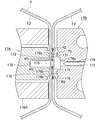
- a horizontal sealing device for a filling and packaging machine is shown, in which (a) is a partially enlarged horizontal sectional view, and (b) is an anvil portion along the line bb of (a). It is an enlarged front view. It is a partially enlarged vertical sectional view of the horizontal sealing device along the line II-II of FIG. It is a partially enlarged vertical sectional view of the horizontal sealing device along the line III-III of FIG. It is a perspective view which shows the whole outline of the conventional filling and wrapping machine. It is a partially enlarged horizontal sectional view which shows the horizontal seal part formed by the horizontal seal device of the filling packaging machine.
- FIGS. 1 to 3 show the details of the horizontal sealing device of the filling and packaging machine according to the embodiment of the present invention.
- FIGS. 2 and 3 the two overlapping portions (T1) of the tubular packaging material (T) and the sealing tape (S) are not shown.
- the structure of the filling and packaging machine of this embodiment is substantially the same as that of the prior art described above with reference to FIG. 4, except for the detailed structure of the horizontal sealing device described later. Omit.
- the ultrasonic horn (17A) and the anvil (17B) of the lateral sealing device extend in the direction orthogonal to the length direction of the tubular packaging material (T) and extend in the direction orthogonal to the length direction of the tubular packaging material (T). It is composed of metal bars facing each other across T).
- the ultrasonic horn (17A) has two upper and lower band-shaped sealing surfaces (171) extending parallel to each other along the length direction on the inner surface facing the tubular packaging material (T). A cutter relief groove (178) is formed between the two sealing surfaces (171).
- This ultrasonic horn (17A) is housed in a stopper (170A) made of a hollow bar having an opening on the inner side surface facing the tubular packaging material (T) so that the sealing surface (171) slightly protrudes from the opening.
- a stopper (170A) made of a hollow bar having an opening on the inner side surface facing the tubular packaging material (T) so that the sealing surface (171) slightly protrudes from the opening.
- the high-frequency electrical energy emitted from the ultrasonic oscillator is converted into mechanical vibration energy by the converter, and this mechanical vibration energy is increased or decreased by the booster and then transmitted to the ultrasonic horn (17A). By doing so, the tubular packaging material (T) can be vibrated with a required amplitude through the ultrasonic horn (17A
- the anvil (17B) has two strips on the inner surface facing the tubular packaging material (T), extending parallel to each other in the length direction and facing the two sealing surfaces (171) of the ultrasonic horn (17A). Has a sealing surface (172).
- the slit (174) formed between the two sealing surfaces (172) accommodates a cutter (175) for cutting the lateral sealing portion at an intermediate position in the width.
- a step (174a) facing the ultrasonic horn (17A) side and perpendicular to the depth direction of the slit (174) is formed.
- the upper adjacent portion of the upper sealing surface (172) and the lower adjacent portion of the lower sealing surface (172) have horizontal grooves (176) having a V-shaped cross section extending along the length direction of these sealing surfaces (172). Each is formed. These horizontal grooves (176) form a sealant layer on the inner surface of the two flat packaging material (T) portions adjacent to the inner surface of the two flat packaging material (T) portions fused to each other by the horizontal seal. This is to allow a part of the molten thermoplastic resin to be extruded to form a resin pool (R2). Further, as shown in FIGS. 2 and 3, the upper sealing surface (171) of the ultrasonic horn (17A) has an upper end edge substantially the same as the central portion of the width of the upper horizontal groove (176) of the anvil (17B).
- the lower sealing surface (171) of the ultrasonic horn (17A) is formed so as to be in a height position, and its lower end edge is approximately the same as the center of the width of the lower horizontal groove (176) of the anvil (17B). It is formed so as to be at the same height position, and the arrangement configuration of both sealing surfaces (171) makes it easy for the resin pool (R2) to be formed.
- the presence of these resin pools (R2) improves the sealing performance of the lateral seal portion.
- FIGS. 2 and 3 the cutting side of the tubular packaging material (T) opposite to the resin pool (R2) with the two flat packaging materials (T) portions to be laterally sealed sandwiched between them.
- a similar resin pool (R3) is formed in the portion.
- the absorbing portion (173) is composed of a stepped isosceles trapezoidal groove (173) extending in the vertical direction orthogonal to the length direction of both sealing surfaces (172).
- the inner step (T11) and the outer step (T12) of the overlap portion (T1) of the tubular packaging material (T) are usually formed on the inclined surfaces (173a) on both sides of the concave groove (173).
- the end faces of the packaging material (T) forming these steps) are located respectively.
- recesses (177) slightly deeper than the depth of the concave groove (173) are formed.
- the absorbing portion is not limited to the illustrated form, and may be formed of, for example, a concave groove having a concave arc shape in a cross section, an uneven portion having a corrugated cross section, or the like. Further, the absorbing portion may be formed on the sealing surface of the ultrasonic horn. Further, the absorbing portion may not be formed on the sealing surface.
- the upper and lower sealing surfaces (172) of the anvil (17B) can intersect the edge surface (S1) of one of the sealing tapes (S) (left side in FIG. 1) when viewed from the front during horizontal sealing.
- the position of the edge surface (S1) of one of the sealing tapes (S) (left side in FIG. 1) is indicated by a chain line (L1), and the position of the other (right side in FIG. 1).
- the position of the edge face (S2) is indicated by the chain line (L2). Further, the above-mentioned "viewed from the front” refers to a state when viewed from the side facing the seal surface (172) (for example, the left side in FIGS. 2 and 3).
- the end edges (S1) (S2) of the sealing tape (S) and the tubular packaging material (T) are separated.
- the inner surfaces of the two flat packaging materials (T) that have been crushed and crimped to each other may not be fused, and a penetrating cavity (G) may be formed between the two (see FIG. 5).
- the molten resin formed by melting a part of the thermoplastic resin constituting the sealant layer on the inner surface side of the tubular packaging material (T) by ultrasonic vibration moves in the passage and the sealing tape (S). It flows into the cavity facing each end edge surface (S1) (S2) of. As a result, the cavity is filled with the resin (R1), so that the contents do not leak through the cavity.
- the first groove (179a) is a plurality of parallel grooves extending so as to be able to intersect diagonally with one end edge surface (S1) of the sealing tape (S) when viewed from the front at the time of lateral sealing. Consists of an inclined groove.
- the second groove (179b) is a plurality of inclined grooves parallel to each other extending so as to be able to diagonally intersect the other end edge surface (S2) of the sealing tape (S) when viewed from the front at the time of lateral sealing. Consists of.
- the molten resin is applied to both the wetted side and the cut side. Each flows toward. Then, the flow of the molten resin collides with each end edge surface (S1) (S2) of the sealing tape (S) to fill the hollow portion. Therefore, if the directions of the first groove (179a) and the second groove (179b) are set symmetrically in the vertical and horizontal directions as shown in FIG. 1 (b), the end faces (S1) (S1) of the sealing tape (S) are set. Since the flow of the molten resin with respect to S2) is the same, the sealing conditions for the laterally sealed portion can be made uniform.
- the inclination directions of these grooves (179a) and (179b) may extend in the direction opposite to that in FIG. 1 (b).
- the directions of the first groove (179a) and the second groove (179b) are set as shown in FIG. 1 (b)
- the molten resin toward the liquid contact side is compared with the case of the opposite direction. Since there is a high probability that the flow of water will hit each end face (S1) (S2) of the sealing tape (S), each end face (S1) (S2) of the sealing tape (S) will be closer to the wetted side. ) Will be filled with resin (R1), so it is considered that it is possible to more reliably prevent the contents from leaking through the cavity.
- the first groove (179a) and the second groove (179b) are formed so as to cross the upper and lower sealing surfaces (172). However, the first groove (179a) and the second groove (179b) may be non-transverse so as not to reach either or both of the upper and lower edges of the upper and lower sealing surfaces (172). Is. In particular, if these grooves (179a) (179b) do not reach either the upper or lower edge of each of the upper and lower sealing surfaces (172), in other words, one of these grooves (179a) (179b). It is considered that the flow direction of the molten resin can be controlled when the end of the resin is blocked.
- first groove (179a) and one second groove (179b) are formed on the upper and lower sealing surfaces (172), but they are spaced apart as in the above embodiment. If a plurality of the sealing tapes (S) are formed, even if the positions of the sealing tapes (S) are displaced along the length direction of the upper and lower sealing surfaces (172) during horizontal sealing, each end edge of the sealing tape (S) is formed. By filling the cavity formed at the position facing the surfaces (S1) and (S2) with the resin (R1), the effect of preventing the occurrence of sealing failure can be obtained more reliably.
- the plurality of inclined grooves constituting the first groove (179a) and the second groove (179b) are arranged in parallel with each other at an equal pitch as shown in FIG. 1, and some or all of the inclined grooves are arranged at equal pitches. May be non-parallel or the pitch may be changed.
- the first groove (179a) and the second groove (179b) may be an oblique linear groove as in the above embodiment, or may be a curved, crank-shaped, or wavy groove.
- a plurality of V-shaped or Y-shaped grooves viewed from the front are alternately turned upside down along the length direction of the sealing surface (172). It is also possible to adopt a configuration mode in which the orientation is arranged.
- the first groove (179a) and the second groove (179b) are formed on the sealing surface (172) of the anvil (17B) as in the above embodiment, and also on the sealing surface (172) of the ultrasonic horn (17A). It may be formed in 171).
- the width (W) of the first groove (179a) and the second groove (179b) is preferably 0.05 to 0.4 mm, more preferably 0.1 to 0.3 mm. If the width (W) is less than 0.05 mm, it becomes difficult for the molten resin to flow toward each end face (S1) (S2) of the sealing tape (S), and each end face of the sealing tape (S).
- the depth (D) of the first groove (179a) and the second groove (179b) is preferably 0.03 to 0.4 mm, more preferably 0.05 to 0.2 mm.
- the depth (D) is less than 0.03 mm, it becomes difficult for the molten resin to flow toward the edge faces (S1) (S2) of the sealing tape (S), and each edge of the sealing tape (S). There is a risk that the cavities created at the positions facing the surfaces (S1) and (S2) will not be filled.
- the depth (D) exceeds 0.4 mm, the flow velocity of the molten resin flowing toward each end edge surface (S1) (S2) of the sealing tape (S) becomes slow, and the sealing tape (S) becomes slower. There is a risk that the cavity formed at the position facing each end edge surface (S1) (S2) will not be filled with the resin (R1).
- the cross-sectional shape of the first groove (179a) and the second groove (179b) can be, for example, V-shaped, U-shaped, or arc-shaped, but is preferably V-shaped, whereby the molten resin is formed. It is considered that it becomes easier to flow toward each end edge surface (S1) (S2) of the sealing tape (S).
- the inclination ( ⁇ ) of the first groove (179a) and the second groove (179b) with respect to each end face surface (S1) (S2) of the sealing tape (S) is preferably 25 to 80 °, more preferably. It is preferably 35 to 55 °.
- the inclination ( ⁇ ) is less than 25 °, it is necessary to increase the number of the first groove (179a) and the second groove (179b) in consideration of the deviation amount of the sealing tape (S), and the sealing tape. There is a risk of affecting the sealing performance at locations other than those corresponding to the end edges (S1) and (S2) of (S).
- the inclination ( ⁇ ) exceeds 80 °, the molten resin may be difficult to flow toward each end edge surface (S1) (S2) of the sealing tape (S).
- the first groove (179a) and the second groove (179b) are each one, the first groove (179a) with respect to each end edge surface (S1) (S2) of the sealing tape (S) is used.
- the inclination ( ⁇ ) of the second groove (179b) are preferably 55 ° or more in consideration of the amount of deviation of the sealing tape (S).
- the number of the first groove (179a) and the second groove (179b) is preferably 2 to 10, and more preferably 4 to 8. If there is only one, there is a risk that it will not be possible to handle the expected amount of displacement of the sealing tape (S). On the other hand, if the number exceeds 10, there is a possibility that the sealing property other than the portion corresponding to each end edge surface (S1) (S2) of the sealing tape (S) may be affected.
- the pitch (P) of the first groove (179a) and the second groove (179b) is preferably 0.2 to 0.8 mm, more preferably 0.3 to 0.7 mm. If the pitch (P) is less than 0.2 mm, the sealing area becomes too small and a sealing failure may occur. On the other hand, if the pitch (P) exceeds 0.8 mm, the cavity formed at the position facing each end edge surface (S1) (S2) of the sealing tape (S) may not be filled with the resin (R1).
- the present invention is a filling and packaging machine for filling and packaging contents such as fluid foods and beverages in a container formed of a web-like packaging material mainly composed of paper, and an ultrasonic seal type used for the filling and packaging machine. It is suitably used as a horizontal sealing device.
Landscapes
- Engineering & Computer Science (AREA)
- Mechanical Engineering (AREA)
- Package Closures (AREA)
Abstract
Description
この充填包装機(10)は、ロール状に巻かれたウェブ状包材(M)を支持しているリワインダ(11)と、リワインダ(11)からウェブ状包材(M)を順次巻き戻す巻戻し装置(12)と、巻き戻されたウェブ状包材(M)の片面の一端縁部に熱可塑性樹脂よりなるシーリングテープ(S)をその幅の一部がはみ出すように貼り付けるテープ貼り付け装置(13)と、ウェブ状包材(M)を過酸化水素水等の殺菌液に浸漬して殺菌を行う殺菌槽(14)と、ウェブ状包材(M)の両端縁部を所定幅ずつオーバーラップさせて縦シールすることによりチューブ状包材(T)を形成するとともに、オーバーラップ部(T1)の内側の段差(T11)(ウェブ状包材の一端縁面)を被覆するようにチューブ状包材(T)の内面にシーリングテープ(S)のはみ出し部を貼り付ける縦シール装置(15)と、チューブ状包材(T)内に上方から挿入された充填管(16a)によってチューブ状包材(T)内に流動状の内容物を充填する内容物充填装置(16)と、内容物が充填されたチューブ状包材(T)を容器1つ分に相当する長さ毎に横シールして横シール部の幅中間で切断することにより中間形態である枕状の内容物充填容器(C1)を形成する横シール装置(17)と、上記容器(C1)を完成形態である直方体状の内容物充填容器(C2)に成形する容器完成装置(18)とを備えている。
例えば下記特許文献1,2に開示されているように、超音波シール式の横シール装置(17)の場合、チューブ状包材(T)を挟んで開閉自在に配された超音波ホーン(17A)およびアンビル(17B)を備えている。超音波ホーン(17A)およびアンビル(17B)には、チューブ状包材(T)の長さ方向と直交する方向にのびた互いに向かい合うシール面が形成されている。また、図示は省略したが、超音波ホーン(17A)およびアンビル(17B)には、チューブ状包材(T)をその両側から挟み付けることにより所定の容器形状(例えば横断面正方形)に予備成形する成形フラップが付設されている。
横シール時には、チューブ状包材(T)を、所定の高さ位置において、超音波ホーン(17A)およびアンビル(17B)のシール面により所定の加圧力で局部的に挟み込んで変形させ、それによって偏平状となされた2つの包材(T)部分どうしを圧着させた状態で、超音波発振器を作動させる。すると、図5に示すように、圧着された2つの包材(T)部分の内面どうしが融着されるとともに、シーリングテープ(S)がオーバーラップ部(T1)と反対側の包材(T)部分の内面に融着される。
しかしながら、シーリングテープ(S)の種類によっては、例えばシーリングテープ(S)の材料として硬いものが使用されていたり、その厚みが大きかったりすると、シーリングテープ(S)の各端縁面(S1)(S2)と上記包材(T)部分の内面とが融着されず、図5に示すように、両者の間に貫通状の空洞部(G)が生じ、同空洞部(G)を通じて内容物が漏れ出すシール不良が発生することが稀にあった。
チューブ状包材を挟んで開閉自在に設けられかつチューブ状包材の長さ方向と直交する方向にのびた互いに向かい合うシール面が形成されている超音波ホーンおよびアンビルを有しており、
超音波ホーンおよびアンビルのうちいずれか一方のシール面に、横シール時に正面より見てシーリングテープの一方の端縁面と交差しうるようにのびている第1の溝と、横シール時に正面より見てシーリングテープの他方の端縁面と交差しうるようにのびている第2の溝とが形成されている、充填包装機の横シール装置。
ウェブ状包材の両端縁部を所定幅ずつオーバーラップさせて縦シールすることによりチューブ状包材を形成するとともに、オーバーラップ部の内側の段差を被覆しうるようにチューブ状包材の内面にシーリングテープのはみ出し部を貼り付ける縦シール装置と、
チューブ状包材を挟んで開閉自在に設けられかつチューブ状包材の長さ方向と直交する方向にのびた互いに向かい合うシール面が形成されている超音波ホーンおよびアンビルを有しており、内容物が充填されたチューブ状包材を容器1つ分の長さ毎に横シールする横シール装置とを備えている充填包装機であって、
横シール装置が、上記1)または2)の横シール装置よりなる、充填包装機。
すなわち、上記2つの包材部分のうち第1の溝および第2の溝に対応する箇所では、超音波ホーンおよびアンビルのシール面による加圧力が弱くなる。その結果、圧着された2つの包材部分どうしの間に、シーリングテープの各端縁面と交差するように通路が形成される。超音波振動によりチューブ状包材の内面側のシーラント層を構成する熱可塑性樹脂の一部が溶融して形成された溶融樹脂が、同通路内を移動して、シーリングテープの各端縁面に臨んだ空洞部に流れ込む。これにより、同空洞部が樹脂で埋められるので、同空洞部を通じて内容物が漏れ出すことがない。
図1~図3は、この発明の実施形態に係る充填包装機の横シール装置の詳細を示したものである。なお、図2および図3では、チューブ状包材(T)のオーバーラップ部(T1)の2つの重なり部分およびシーリングテープ(S)の図示を省略している。
また、この実施形態の充填包装機の構造は、後述する横シール装置の詳細構造を除けば、図4を参照して先に説明した従来技術と実質的に同じであるので、重複する説明は省略する。
この超音波ホーン(17A)は、チューブ状包材(T)に臨む内側面に開口を有する中空バーよりなるストッパ(170A)に、同開口からシール面(171)が僅かに突出するように収容されている。
また、詳しい図示は省略したが、超音波発振器から発せられた高周波電気エネルギーがコンバータで機械振動エネルギーに変換され、この機械振動エネルギーが、ブースターで増減された後、超音波ホーン(17A)に伝達されることにより、超音波ホーン(17A)を通してチューブ状包材(T)が所要の振幅で振動させられるようになっている。
2つのシール面(172)どうしの間に形成されたスリット(174)には、横シール部を幅中間位置で切断するためのカッター(175)が出没自在に収容されている。スリット(174)の開口の上下縁部には、超音波ホーン(17A)側を向いた、スリット(174)の深さ方向に対して垂直な段差(174a)が形成されている。
上シール面(172)の上隣部分および下シール面(172)の下隣部分には、これらのシール面(172)の長さ方向に沿ってのびる横断面V形の水平溝(176)がそれぞれ形成されている。これらの水平溝(176)は、横シールによって互いに融着される偏平状の2つの包材(T)部分の内面に隣接する箇所に、同包材(T)部分の内面のシーラント層を構成する溶融した熱可塑性樹脂の一部が押し出されて樹脂溜まり(R2)が形成されるようにするためのものである。また、図2および図3に示すように、超音波ホーン(17A)の上シール面(171)は、その上端縁がアンビル(17B)の上側の水平溝(176)の幅中央部とほぼ同じ高さ位置になるように形成されており、超音波ホーン(17A)の下シール面(171)は、その下端縁がアンビル(17B)の下側の水平溝(176)の幅中央部とほぼ同じ高さ位置になるように形成されており、これら両シール面(171)の配置構成も相俟って、上記樹脂溜まり(R2)が形成され易くなっている。そして、これらの樹脂溜まり(R2)の存在により、横シール部のシール性が向上する。なお、図2および図3に示すように、チューブ状包材(T)のうち横シールされる偏平状の2つの包材(T)部分を挟んで上記樹脂溜まり(R2)と反対の切断側部分にも、同様の樹脂溜まり(R3)が形成される。
なお、吸収部は、図示の形態には限定されず、例えば、横断面凹弧状の凹溝や、横断面波形の凹凸部などで構成されてもよい。また、吸収部は、超音波ホーンのシール面に形成されていてもよい。さらに、吸収部をシール面に形成しない場合もありうる。
前述したように、横シール装置(17)によるチューブ状包材(T)の横シールに際して、シーリングテープ(S)の各端縁面(S1)(S2)と、チューブ状包材(T)が押し潰されて互いに圧着された2つの偏平状の包材(T)部分の内面とが融着されず、両者の間に貫通状の空洞部(G)が生じることがあるが(図5参照)、その場合であっても、アンビル(17B)の上下各シール面(172)に形成された上記第1の溝(179a)および第2の溝(179b)によって以下のような作用効果が奏され、シール不良の発生が確実に防止されるようになっている。すなわち、圧着された2つの包材(T)部分のうち第1の溝(179a)および第2の溝(179b)に対応する箇所では、超音波ホーン(17A)およびアンビル(17B)のシール面(171)(172)による加圧力が弱くなる。その結果、圧着された2つの包材(T)部分どうしの間に、シーリングテープ(S)の各端縁面(S1)(S2)と交差するように通路が形成される。超音波振動によりチューブ状包材(T)の内面側のシーラント層を構成する熱可塑性樹脂の一部が溶融して形成された溶融樹脂が、同通路内を移動して、シーリングテープ(S)の各端縁面(S1)(S2)に臨んだ空洞部に流れ込む。これにより、同空洞部が樹脂(R1)で埋められるので、同空洞部を通じて内容物が漏れることがなくなる。
圧着された2つの包材(T)部分における第1の溝(179a)および第2の溝(179b)に対応する箇所に形成された通路において、溶融樹脂は、接液側と切断側の両方に向かってそれぞれ流れる。そして、溶融樹脂の流れがシーリングテープ(S)の各端縁面(S1)(S2)にぶつかることで、上記空洞部が埋められる。
従って、第1の溝(179a)および第2の溝(179b)の向きを図1(b)のように上下左右対称に設定すれば、シーリングテープ(S)の各端縁面(S1)(S2)に対する溶融樹脂の流れの当たり方が同一となるので、横シールされる部分のシール条件を揃えることができる。
なお、シール条件を揃えるという点から見れば、これらの溝(179a)(179b)の傾斜方向は、図1(b)とは逆向きにのびていても構わない。
尤も、第1の溝(179a)および第2の溝(179b)の向きを図1(b)に示すように設定した場合、これと逆向きの場合と比べて、接液側に向かう溶融樹脂の流れがシーリングテープ(S)の各端縁面(S1)(S2)に当たる確率が高くなるため、より接液側に近い箇所で、シーリングテープ(S)の各端縁面(S1)(S2)に臨んだ空洞部が樹脂(R1)で埋められることになるので、同空洞部を通じて内容物が漏れるのをより一層確実に防止することができると考えられる。
これら第1の溝(179a)および第2の溝(179b)は、上下各シール面(172)を横断するように形成されている。但し、第1の溝(179a)および第2の溝(179b)は、上下各シール面(172)の上下いずれか一方の縁または両方の縁に達しない非横断状のものとすることも可能である。特に、これらの溝(179a)(179b)を、上下各シール面(172)の上下いずれか一方の縁に達しないものとした場合、換言すれば、これらの溝(179a)(179b)の一方の端を堰き止めた場合、溶融樹脂の流れ方向を制御することが可能になると考えられる。
上下各シール面(172)に形成される第1の溝(179a)および第2の溝(179b)は、少なくとも1つずつ形成されていれば足りるが、上記実施形態のように間隔をおいて複数個ずつ形成されていれば、横シール時にシーリングテープ(S)の位置が上下シール面(172)の長さ方向に沿ってずれた場合であっても、シーリングテープ(S)の各端縁面(S1)(S2)に臨む位置に生じた空洞部を樹脂(R1)で埋めることによりシール不良の発生を防止する効果がより確実に得られる。なお、第1の溝(179a)および第2の溝(179b)をそれぞれ構成する複数の傾斜溝は、図1に示すように互いに平行で等ピッチに配列する他、一部または全部の傾斜溝を非平行としたり、ピッチを変えたりしても構わない。
第1の溝(179a)および第2の溝(179b)は、上記実施形態のような斜め直線状の溝とする他、曲線状、クランク状、波線状の溝としてもよい。また、第1の溝(179a)および第2の溝(179b)として、正面より見てV形やY形をした複数の溝をシール面(172)の長さ方向に沿って交互に上下逆向きに配列させた構成態様も採り得る。
また、第1の溝(179a)および第2の溝(179b)は、上記実施形態のようにアンビル(17B)のシール面(172)に形成する他、超音波ホーン(17A)のシール面(171)に形成する場合もあり得る。
第1の溝(179a)および第2の溝(179b)の幅(W)は、0.05~0.4mmであるのが好ましく、より好ましくは0.1~0.3mmである。幅(W)が0.05mm未満であると、溶融樹脂がシーリングテープ(S)の各端縁面(S1)(S2)に向かって流れにくくなって、シーリングテープ(S)の各端縁面(S1)(S2)に臨む位置に生じた空洞部が埋まらなくなるおそれがある。一方、幅(W)が0.4mmを超えると、シーリングテープ(S)の各端縁面(S1)(S2)に向かって流れる溶融樹脂の流速が遅くなって、シーリングテープ(S)の各端縁面(S1)(S2)に臨む位置に生じた空洞部が樹脂(R1)によって埋まらなくなるおそれがある上、シール面(172)の面積が減少して、シール性に影響を及ぼすおそれがある。
第1の溝(179a)および第2の溝(179b)の深さ(D)は、0.03~0.4mmであるのが好ましく、より好ましくは0.05~0.2mmである。深さ(D)が0.03mm未満であると、溶融樹脂がシーリングテープ(S)の各端縁面(S1)(S2)に向かって流れにくくなって、シーリングテープ(S)の各端縁面(S1)(S2)に臨む位置に生じた空洞部が埋まらなくなるおそれがある。一方、深さ(D)が0.4mmを超えると、シーリングテープ(S)の各端縁面(S1)(S2)に向かって流れる溶融樹脂の流速が遅くなって、シーリングテープ(S)の各端縁面(S1)(S2)に臨む位置に生じた空洞部が樹脂(R1)によって埋まらなくなるおそれがある。
第1の溝(179a)および第2の溝(179b)の横断面形状は、例えばV形、U形、円弧形とすることができるが、好ましくはV形であり、それによって溶融樹脂がシーリングテープ(S)の各端縁面(S1)(S2)に向かって流れ易くなると考えられる。
シーリングテープ(S)の各端縁面(S1)(S2)に対する第1の溝(179a)および第2の溝(179b)の傾き(θ)は、25~80°であるのが好ましく、より好ましくは35~55°である。傾き(θ)が25°未満であると、シーリングテープ(S)のずれ量を考慮して第1の溝(179a)および第2の溝(179b)の数を多くする必要があり、シーリングテープ(S)の各端縁面(S1)(S2)に対応する箇所以外でのシール性に影響を及ぼすおそれがある。一方、傾き(θ)が80°を超えると、溶融樹脂がシーリングテープ(S)の各端縁面(S1)(S2)に向かって流れにくくなるおそれがある。なお、第1の溝(179a)および第2の溝(179b)をそれぞれ1本とする場合には、シーリングテープ(S)の各端縁面(S1)(S2)に対する第1の溝(179a)および第2の溝(179b)の傾き(θ)は、シーリングテープ(S)のずれ量を考慮して、55°以上となされるのが好ましい。
第1の溝(179a)および第2の溝(179b)の数は、2~10本であるのが好ましく、より好ましくは4~8本である。1本のみであると、想定されるシーリングテープ(S)のずれ量に対応できなくなるおそれがある。一方、10本を超えると、シーリングテープ(S)の各端縁面(S1)(S2)に対応する箇所以外でのシール性に影響を及ぼすおそれがある。
第1の溝(179a)および第2の溝(179b)のピッチ(P)は、0.2~0.8mmであるのが好ましく、より好ましくは0.3~0.7mmである。ピッチ(P)が0.2mm未満であるとシール面積が小さくなりすぎてシール不良を生じるおそれがある。一方、ピッチ(P)が0.8mmを超えると、シーリングテープ(S)の各端縁面(S1)(S2)に臨む位置に生じた空洞部が樹脂(R1)によって埋まらなくなるおそれがある。
(13):テープ貼り付け装置
(15):縦シール装置
(17):横シール装置
(17A):超音波ホーン
(171):(超音波ホーンの)シール面
(17B):アンビル
(172):(アンビルの)シール面
(179a):第1の溝
(179b):第2の溝
(M):ウェブ状包材
(T):チューブ状包材
(T1):オーバーラップ部
(T11):内側の段差
(S):シーリングテープ
(S1):一方の端縁面
(S2):他方の端縁面
Claims (3)
- 両面にシーラント層を有するウェブ状包材から形成される容器に内容物を充填して包装する充填包装機において、ウェブ状包材の両端縁部を所定幅ずつオーバーラップさせて縦シールすることによりチューブ状に形成されているとともにオーバーラップ部の内側の段差を被覆しうるように内面にシーリングテープが貼り付けられているチューブ状包材を、その内部に内容物が充填された状態で、容器1つ分の長さ毎に横シールする横シール装置であって、
チューブ状包材を挟んで開閉自在に設けられかつチューブ状包材の長さ方向と直交する方向にのびた互いに向かい合うシール面が形成されている超音波ホーンおよびアンビルを有しており、
超音波ホーンおよびアンビルのうちいずれか一方のシール面に、横シール時に正面より見てシーリングテープの一方の端縁面と交差しうるようにのびている第1の溝と、横シール時に正面より見てシーリングテープの他方の端縁面と交差しうるようにのびている第2の溝とが形成されている、充填包装機の横シール装置。 - 第1の溝が、横シール時に正面より見てシーリングテープの一方の端縁面と斜めに交差しうるようにのびている1つの傾斜溝または互いに平行な複数の傾斜溝よりなり、第2の溝が、横シール時に正面より見てシーリングテープの他方の端縁面と斜めに交差しうるようにのびている1つの傾斜溝または互いに平行な複数の傾斜溝よりなる、請求項1記載の充填包装機の横シール装置。
- 両面にシーラント層を有するウェブ状包材の片面の一端縁部にシーリングテープをその幅の一部がはみ出すように貼り付けるテープ貼り付け装置と、
ウェブ状包材の両端縁部を所定幅ずつオーバーラップさせて縦シールすることによりチューブ状包材を形成するとともに、オーバーラップ部の内側の段差を被覆しうるようにチューブ状包材の内面にシーリングテープのはみ出し部を貼り付ける縦シール装置と、
チューブ状包材を挟んで開閉自在に設けられかつチューブ状包材の長さ方向と直交する方向にのびた互いに向かい合うシール面が形成されている超音波ホーンおよびアンビルを有しており、内容物が充填されたチューブ状包材を容器1つ分の長さ毎に横シールする横シール装置とを備えている充填包装機であって、
横シール装置が、請求項1または2記載の横シール装置よりなる、充填包装機。
Priority Applications (2)
| Application Number | Priority Date | Filing Date | Title |
|---|---|---|---|
| JP2021561272A JP7618243B2 (ja) | 2019-11-28 | 2020-11-10 | 充填包装機およびこれに用いられる横シール装置 |
| EP20893700.3A EP4067246A4 (en) | 2019-11-28 | 2020-11-10 | FILM WRAPPING MACHINE AND SIDE SEALING DEVICE USED IN THE SAME |
Applications Claiming Priority (2)
| Application Number | Priority Date | Filing Date | Title |
|---|---|---|---|
| JP2019215192 | 2019-11-28 | ||
| JP2019-215192 | 2019-11-28 |
Publications (1)
| Publication Number | Publication Date |
|---|---|
| WO2021106545A1 true WO2021106545A1 (ja) | 2021-06-03 |
Family
ID=76130164
Family Applications (1)
| Application Number | Title | Priority Date | Filing Date |
|---|---|---|---|
| PCT/JP2020/041847 Ceased WO2021106545A1 (ja) | 2019-11-28 | 2020-11-10 | 充填包装機およびこれに用いられる横シール装置 |
Country Status (3)
| Country | Link |
|---|---|
| EP (1) | EP4067246A4 (ja) |
| JP (1) | JP7618243B2 (ja) |
| WO (1) | WO2021106545A1 (ja) |
Cited By (1)
| Publication number | Priority date | Publication date | Assignee | Title |
|---|---|---|---|---|
| JP2023018947A (ja) * | 2021-07-28 | 2023-02-09 | 株式会社東陽機械製作所 | 横シール装置 |
Citations (7)
| Publication number | Priority date | Publication date | Assignee | Title |
|---|---|---|---|---|
| JP2008543688A (ja) * | 2005-07-08 | 2008-12-04 | テトラ ラバル ホールデイングス エ フイナンス ソシエテ アノニム | 横シーリングのためのデバイス及び方法 |
| JP4282179B2 (ja) | 1999-09-30 | 2009-06-17 | 四国化工機株式会社 | 超音波シール装置 |
| JP4316053B2 (ja) | 1999-07-05 | 2009-08-19 | 四国化工機株式会社 | 超音波シール装置 |
| JP2011519786A (ja) * | 2008-04-29 | 2011-07-14 | テトラ ラバル ホールデイングス エ フイナンス ソシエテ アノニム | 食品の密封パッケージを製造するためのシール用顎状掴み具 |
| WO2013002148A1 (ja) * | 2011-06-28 | 2013-01-03 | 旭化成ケミカルズ株式会社 | 密封包装体並びにその製造方法及び製造装置 |
| US20130228288A1 (en) * | 2010-10-29 | 2013-09-05 | Robert Bosch Gmbh | Apparatus for cutting a packaging material for a package |
| JP2017071442A (ja) * | 2015-10-08 | 2017-04-13 | オリヒロエンジニアリング株式会社 | 縦型充填包装機、該縦型充填包装機の横シール装置、および包装袋入り液体製品の製造方法 |
Family Cites Families (3)
| Publication number | Priority date | Publication date | Assignee | Title |
|---|---|---|---|---|
| DE102006045338B4 (de) * | 2006-09-22 | 2008-08-21 | Sig Technology Ag | Vorrichtung zum Versiegeln von mindestens zwei Lagen eines aufeinander gefalteten Giebels einer eine Längsnaht aufweisenden Mehrschichtverbundpackung und eine damit gebildete Mehrschichtverbundpackung |
| EP3090860B1 (en) * | 2015-05-05 | 2019-09-11 | Tetra Laval Holdings & Finance S.A. | Induction heating sealing device |
| CN111094138B (zh) * | 2017-10-03 | 2022-04-05 | 凸版印刷株式会社 | 超声波密封用砧座及超声波密封装置 |
-
2020
- 2020-11-10 JP JP2021561272A patent/JP7618243B2/ja active Active
- 2020-11-10 EP EP20893700.3A patent/EP4067246A4/en not_active Withdrawn
- 2020-11-10 WO PCT/JP2020/041847 patent/WO2021106545A1/ja not_active Ceased
Patent Citations (7)
| Publication number | Priority date | Publication date | Assignee | Title |
|---|---|---|---|---|
| JP4316053B2 (ja) | 1999-07-05 | 2009-08-19 | 四国化工機株式会社 | 超音波シール装置 |
| JP4282179B2 (ja) | 1999-09-30 | 2009-06-17 | 四国化工機株式会社 | 超音波シール装置 |
| JP2008543688A (ja) * | 2005-07-08 | 2008-12-04 | テトラ ラバル ホールデイングス エ フイナンス ソシエテ アノニム | 横シーリングのためのデバイス及び方法 |
| JP2011519786A (ja) * | 2008-04-29 | 2011-07-14 | テトラ ラバル ホールデイングス エ フイナンス ソシエテ アノニム | 食品の密封パッケージを製造するためのシール用顎状掴み具 |
| US20130228288A1 (en) * | 2010-10-29 | 2013-09-05 | Robert Bosch Gmbh | Apparatus for cutting a packaging material for a package |
| WO2013002148A1 (ja) * | 2011-06-28 | 2013-01-03 | 旭化成ケミカルズ株式会社 | 密封包装体並びにその製造方法及び製造装置 |
| JP2017071442A (ja) * | 2015-10-08 | 2017-04-13 | オリヒロエンジニアリング株式会社 | 縦型充填包装機、該縦型充填包装機の横シール装置、および包装袋入り液体製品の製造方法 |
Non-Patent Citations (1)
| Title |
|---|
| See also references of EP4067246A4 |
Cited By (2)
| Publication number | Priority date | Publication date | Assignee | Title |
|---|---|---|---|---|
| JP2023018947A (ja) * | 2021-07-28 | 2023-02-09 | 株式会社東陽機械製作所 | 横シール装置 |
| JP7702724B2 (ja) | 2021-07-28 | 2025-07-04 | 株式会社東陽機械製作所 | 横シール装置 |
Also Published As
| Publication number | Publication date |
|---|---|
| JP7618243B2 (ja) | 2025-01-21 |
| JPWO2021106545A1 (ja) | 2021-06-03 |
| EP4067246A4 (en) | 2024-03-27 |
| EP4067246A1 (en) | 2022-10-05 |
Similar Documents
| Publication | Publication Date | Title |
|---|---|---|
| JP4615049B2 (ja) | 横シーリングのためのデバイス及び方法 | |
| US20180222617A1 (en) | Anvil and ultrasonic sealing apparatus | |
| JP7525114B2 (ja) | 充填包装機、内容物充填容器およびその製造方法 | |
| WO2021106545A1 (ja) | 充填包装機およびこれに用いられる横シール装置 | |
| JP3329860B2 (ja) | ヒートシールロール | |
| JP4451244B2 (ja) | 包装袋のシール方法、包装袋、包装袋のシール装置、および製袋装置 | |
| JP5019538B2 (ja) | 包装袋及び縦形製袋充填包装機 | |
| JP2934851B2 (ja) | 逆止弁付き袋体 | |
| JP6337654B2 (ja) | 包装袋 | |
| JPH04267750A (ja) | 包装袋用積層フィルム | |
| JP7594302B2 (ja) | 製袋充填機における超音波横シール装置 | |
| HK40050144A (en) | Filling packaging machine, content filling container, and manufacturing method therefor | |
| EP4470760A1 (en) | Ultrasonic sealing system and anvil thereof | |
| US20240109707A1 (en) | Packaging bag, method for manufacturing packaging bag, and pressing member | |
| JP2025140620A (ja) | 充填包装機用超音波シール装置 | |
| EP4461513A1 (en) | Ultrasonic sealing system and anvil thereof | |
| JP4244302B2 (ja) | 易開封包装袋 | |
| JP5644316B2 (ja) | パウチ及びその製造方法 | |
| JP2965810B2 (ja) | 医療用バッグ及び医療用バッグの製造方法 | |
| JP2023149053A (ja) | 包装袋 | |
| IT9003535A1 (it) | Metodo per la realizzazione di un materiale laminato a nastro, e materiale ottenuto con tale metodo. | |
| JPH04327138A (ja) | 易開封性包装袋 |
Legal Events
| Date | Code | Title | Description |
|---|---|---|---|
| 121 | Ep: the epo has been informed by wipo that ep was designated in this application |
Ref document number: 20893700 Country of ref document: EP Kind code of ref document: A1 |
|
| ENP | Entry into the national phase |
Ref document number: 2021561272 Country of ref document: JP Kind code of ref document: A |
|
| NENP | Non-entry into the national phase |
Ref country code: DE |
|
| ENP | Entry into the national phase |
Ref document number: 2020893700 Country of ref document: EP Effective date: 20220628 |
|
| WWW | Wipo information: withdrawn in national office |
Ref document number: 2020893700 Country of ref document: EP |