WO2021106593A1 - 非水電解質二次電池、及び非水電解質二次電池の製造方法 - Google Patents
非水電解質二次電池、及び非水電解質二次電池の製造方法 Download PDFInfo
- Publication number
- WO2021106593A1 WO2021106593A1 PCT/JP2020/042220 JP2020042220W WO2021106593A1 WO 2021106593 A1 WO2021106593 A1 WO 2021106593A1 JP 2020042220 W JP2020042220 W JP 2020042220W WO 2021106593 A1 WO2021106593 A1 WO 2021106593A1
- Authority
- WO
- WIPO (PCT)
- Prior art keywords
- density
- positive electrode
- mixture layer
- region
- negative electrode
- Prior art date
- Legal status (The legal status is an assumption and is not a legal conclusion. Google has not performed a legal analysis and makes no representation as to the accuracy of the status listed.)
- Ceased
Links
Images


Classifications
-
- H—ELECTRICITY
- H01—ELECTRIC ELEMENTS
- H01M—PROCESSES OR MEANS, e.g. BATTERIES, FOR THE DIRECT CONVERSION OF CHEMICAL ENERGY INTO ELECTRICAL ENERGY
- H01M10/00—Secondary cells; Manufacture thereof
- H01M10/05—Accumulators with non-aqueous electrolyte
- H01M10/052—Li-accumulators
- H01M10/0525—Rocking-chair batteries, i.e. batteries with lithium insertion or intercalation in both electrodes; Lithium-ion batteries
-
- H—ELECTRICITY
- H01—ELECTRIC ELEMENTS
- H01M—PROCESSES OR MEANS, e.g. BATTERIES, FOR THE DIRECT CONVERSION OF CHEMICAL ENERGY INTO ELECTRICAL ENERGY
- H01M50/00—Constructional details or processes of manufacture of the non-active parts of electrochemical cells other than fuel cells, e.g. hybrid cells
- H01M50/10—Primary casings; Jackets or wrappings
- H01M50/147—Lids or covers
-
- H—ELECTRICITY
- H01—ELECTRIC ELEMENTS
- H01M—PROCESSES OR MEANS, e.g. BATTERIES, FOR THE DIRECT CONVERSION OF CHEMICAL ENERGY INTO ELECTRICAL ENERGY
- H01M10/00—Secondary cells; Manufacture thereof
- H01M10/05—Accumulators with non-aqueous electrolyte
- H01M10/052—Li-accumulators
-
- H—ELECTRICITY
- H01—ELECTRIC ELEMENTS
- H01M—PROCESSES OR MEANS, e.g. BATTERIES, FOR THE DIRECT CONVERSION OF CHEMICAL ENERGY INTO ELECTRICAL ENERGY
- H01M10/00—Secondary cells; Manufacture thereof
- H01M10/05—Accumulators with non-aqueous electrolyte
- H01M10/058—Construction or manufacture
- H01M10/0585—Construction or manufacture of accumulators having only flat construction elements, i.e. flat positive electrodes, flat negative electrodes and flat separators
-
- H—ELECTRICITY
- H01—ELECTRIC ELEMENTS
- H01M—PROCESSES OR MEANS, e.g. BATTERIES, FOR THE DIRECT CONVERSION OF CHEMICAL ENERGY INTO ELECTRICAL ENERGY
- H01M4/00—Electrodes
- H01M4/02—Electrodes composed of, or comprising, active material
- H01M4/13—Electrodes for accumulators with non-aqueous electrolyte, e.g. for lithium-accumulators; Processes of manufacture thereof
-
- H—ELECTRICITY
- H01—ELECTRIC ELEMENTS
- H01M—PROCESSES OR MEANS, e.g. BATTERIES, FOR THE DIRECT CONVERSION OF CHEMICAL ENERGY INTO ELECTRICAL ENERGY
- H01M50/00—Constructional details or processes of manufacture of the non-active parts of electrochemical cells other than fuel cells, e.g. hybrid cells
- H01M50/10—Primary casings; Jackets or wrappings
- H01M50/102—Primary casings; Jackets or wrappings characterised by their shape or physical structure
- H01M50/103—Primary casings; Jackets or wrappings characterised by their shape or physical structure prismatic or rectangular
-
- H—ELECTRICITY
- H01—ELECTRIC ELEMENTS
- H01M—PROCESSES OR MEANS, e.g. BATTERIES, FOR THE DIRECT CONVERSION OF CHEMICAL ENERGY INTO ELECTRICAL ENERGY
- H01M50/00—Constructional details or processes of manufacture of the non-active parts of electrochemical cells other than fuel cells, e.g. hybrid cells
- H01M50/60—Arrangements or processes for filling or topping-up with liquids; Arrangements or processes for draining liquids from casings
- H01M50/609—Arrangements or processes for filling with liquid, e.g. electrolytes
-
- H—ELECTRICITY
- H01—ELECTRIC ELEMENTS
- H01M—PROCESSES OR MEANS, e.g. BATTERIES, FOR THE DIRECT CONVERSION OF CHEMICAL ENERGY INTO ELECTRICAL ENERGY
- H01M50/00—Constructional details or processes of manufacture of the non-active parts of electrochemical cells other than fuel cells, e.g. hybrid cells
- H01M50/60—Arrangements or processes for filling or topping-up with liquids; Arrangements or processes for draining liquids from casings
- H01M50/609—Arrangements or processes for filling with liquid, e.g. electrolytes
- H01M50/627—Filling ports
-
- H—ELECTRICITY
- H01—ELECTRIC ELEMENTS
- H01M—PROCESSES OR MEANS, e.g. BATTERIES, FOR THE DIRECT CONVERSION OF CHEMICAL ENERGY INTO ELECTRICAL ENERGY
- H01M10/00—Secondary cells; Manufacture thereof
- H01M10/05—Accumulators with non-aqueous electrolyte
- H01M10/056—Accumulators with non-aqueous electrolyte characterised by the materials used as electrolytes, e.g. mixed inorganic/organic electrolytes
- H01M10/0564—Accumulators with non-aqueous electrolyte characterised by the materials used as electrolytes, e.g. mixed inorganic/organic electrolytes the electrolyte being constituted of organic materials only
- H01M10/0566—Liquid materials
-
- Y—GENERAL TAGGING OF NEW TECHNOLOGICAL DEVELOPMENTS; GENERAL TAGGING OF CROSS-SECTIONAL TECHNOLOGIES SPANNING OVER SEVERAL SECTIONS OF THE IPC; TECHNICAL SUBJECTS COVERED BY FORMER USPC CROSS-REFERENCE ART COLLECTIONS [XRACs] AND DIGESTS
- Y02—TECHNOLOGIES OR APPLICATIONS FOR MITIGATION OR ADAPTATION AGAINST CLIMATE CHANGE
- Y02E—REDUCTION OF GREENHOUSE GAS [GHG] EMISSIONS, RELATED TO ENERGY GENERATION, TRANSMISSION OR DISTRIBUTION
- Y02E60/00—Enabling technologies; Technologies with a potential or indirect contribution to GHG emissions mitigation
- Y02E60/10—Energy storage using batteries
-
- Y—GENERAL TAGGING OF NEW TECHNOLOGICAL DEVELOPMENTS; GENERAL TAGGING OF CROSS-SECTIONAL TECHNOLOGIES SPANNING OVER SEVERAL SECTIONS OF THE IPC; TECHNICAL SUBJECTS COVERED BY FORMER USPC CROSS-REFERENCE ART COLLECTIONS [XRACs] AND DIGESTS
- Y02—TECHNOLOGIES OR APPLICATIONS FOR MITIGATION OR ADAPTATION AGAINST CLIMATE CHANGE
- Y02P—CLIMATE CHANGE MITIGATION TECHNOLOGIES IN THE PRODUCTION OR PROCESSING OF GOODS
- Y02P70/00—Climate change mitigation technologies in the production process for final industrial or consumer products
- Y02P70/50—Manufacturing or production processes characterised by the final manufactured product
Definitions
- the present disclosure relates to a non-aqueous electrolyte secondary battery and a method for manufacturing a non-aqueous electrolyte secondary battery.
- Patent Document 1 discloses a cylindrical non-aqueous electrolyte secondary battery including a wound electrode body in which a positive electrode and a negative electrode are spirally wound via a separator.
- a groove is formed in at least one of the mixture layers of the positive electrode and the negative electrode in order to improve the impregnation property of the non-aqueous electrolyte solution in the electrode body and improve the charge / discharge cycle characteristics of the battery. It is formed.
- Patent Document 2 a cylindrical shape in which a low density portion having a density lower than that of the other region is formed along the axial direction of the wound electrode body in at least one mixture layer of the positive electrode and the negative electrode.
- Non-aqueous electrolyte secondary batteries are disclosed.
- Patent Document 2 describes that the impregnation property of the non-aqueous electrolytic solution is improved by providing a low-density portion in a part of the mixture layer.
- the non-aqueous electrolytic solution is generally injected into the inside of the exterior body from the liquid injection portion provided in the exterior body after the electrode body is housed inside the exterior body. It is an important task to impregnate the entire electrode body with a non-aqueous electrolytic solution. In this regard, the techniques disclosed in Patent Documents 1 and 2 still have room for improvement. In the non-aqueous electrolyte secondary battery of Patent Document 1, since the amount of active material in the mixture layer is reduced by forming grooves in the mixture layer, there is a problem in increasing the capacity of the battery.
- the non-aqueous electrolyte secondary battery includes an electrode body in which a plurality of positive electrodes and a plurality of negative electrodes are alternately laminated one by one via a separator, a non-aqueous electrolytic solution, the electrode body, and the non-water.
- a non-aqueous electrolyte secondary battery including an exterior body for accommodating an electrolytic solution, wherein the exterior body is provided with a liquid injection unit for injecting the non-aqueous electrolytic solution, and the plurality of positive electrodes are A positive electrode core body and a positive electrode mixture layer formed on the surface of the positive electrode core body are included, and the plurality of negative electrodes include a negative electrode core body and a negative electrode mixture layer formed on the surface of the negative electrode core body.
- the density of the first region away from the liquid injection portion is lower than the density of the second region close to the liquid injection portion. It is a feature.
- the method for manufacturing a non-aqueous electrolyte secondary battery comprises an electrode body in which a plurality of positive electrodes and a plurality of negative electrodes are alternately laminated one by one via a separator, a non-aqueous electrolyte solution, and an exterior body.
- a method for manufacturing a non-aqueous electrolyte secondary battery wherein the positive electrode mixture layer is formed on the surface of the positive electrode core to prepare the positive electrode, and the negative electrode mixture layer is formed on the surface of the negative electrode core.
- the density of the region located on the first end side of the mixture layer is the first.
- the step of forming the mixture layer so as to be lower than the density of the region located on the second end side opposite to the end of 1 and injecting the non-aqueous electrolyte solution the second end It is characterized in that the non-aqueous electrolytic solution is injected into the inside of the exterior body from the portion side.
- the entire electrode body when the non-aqueous electrolyte solution is injected into the exterior body, the entire electrode body can be impregnated with the non-aqueous electrolyte solution, and the entire electrode body can be impregnated. It is possible to spread the non-aqueous electrolyte solution evenly. For example, if the amount of electrolyte in the electrode varies widely, the battery reaction becomes non-uniform and causes performance deterioration. However, according to the non-aqueous electrolyte secondary battery according to the present disclosure, the occurrence of such a problem is suppressed. it can.
- FIG. 1 is a perspective view showing the appearance of a non-aqueous electrolyte secondary battery which is an example of the embodiment.
- FIG. 2 is a perspective view of an electrode body and a sealing plate as an example of the embodiment.
- FIG. 3 is an exploded perspective view of an electrode body which is an example of the embodiment.
- FIG. 4 is a cross-sectional view showing a part of the electrode body, which is an example of the embodiment, and a front view of the positive electrode.
- FIG. 5 is a diagram for explaining a manufacturing process of a positive electrode which is an example of the embodiment.
- FIG. 1 is a perspective view showing the appearance of the non-aqueous electrolyte secondary battery 10 which is an example of the embodiment
- FIG. 2 is a perspective view of the electrode body 11 and the sealing plate 15 constituting the non-aqueous electrolyte secondary battery 10 (exterior can 14). It is a figure which shows the state which removed.
- the non-aqueous electrolyte secondary battery 10 illustrated in FIG. 1 includes a square container including an outer can 14 and a sealing plate 15 as an outer body, but the outer body is not limited to this, and for example, a metal layer and a resin layer are used. It may be an exterior body composed of a laminating sheet containing the mixture.
- the non-aqueous electrolyte secondary battery 10 is a bottomed square tubular outer can that houses the electrode body 11, the non-aqueous electrolyte solution, the electrode body 11, and the non-aqueous electrolyte solution. 14 and a sealing plate 15 for closing the opening of the outer can 14.
- the non-aqueous electrolyte secondary battery 10 is a so-called square battery.
- the electrode body 11 is a laminated electrode body in which a plurality of positive electrodes 20 and a plurality of negative electrodes 30 are alternately laminated one by one via a separator 40 (see FIG. 3 below for details).
- the outer can 14 is a flat, substantially rectangular parallelepiped-shaped metal container with one end open in the axial direction, and the sealing plate 15 has an elongated rectangular shape.
- the outer can 14 and the sealing plate 15 are made of, for example, a metal material containing aluminum as a main component.
- the height direction of the outer can 14 is referred to as the “vertical direction” of the non-aqueous electrolyte secondary battery 10, the sealing plate 15 side is referred to as “upper”, and the bottom side of the outer can 14 is referred to as “lower”. .. Further, the direction along the longitudinal direction of the sealing plate 15 is defined as the "lateral direction" of the non-aqueous electrolyte secondary battery 10.
- the non-aqueous electrolyte solution contains, for example, a non-aqueous solvent and an electrolyte salt dissolved in the non-aqueous solvent.
- a non-aqueous solvent for example, esters, ethers, nitriles, amides, and a mixed solvent of two or more of these may be used.
- the non-aqueous solvent may contain a halogen substituent in which at least a part of hydrogen in these solvents is substituted with a halogen atom such as fluorine.
- the electrolyte salt for example, a lithium salt such as LiPF 6 is used.
- the non-aqueous electrolyte secondary battery 10 is electrically connected to the positive electrode terminal 12 which is electrically connected to the positive electrode 20 via a positive electrode current collector (not shown) and to the negative electrode 30 via a negative electrode current collector (not shown). It includes a negative electrode terminal 13.
- the positive electrode terminal 12 is arranged on one end side in the longitudinal direction of the sealing plate 15, and the negative electrode terminal 13 is arranged on the other end side in the longitudinal direction of the sealing plate 15.
- the positive electrode terminal 12 and the negative electrode terminal 13 are external connection terminals that are electrically connected to other non-aqueous electrolyte secondary batteries 10, circuits, devices, and the like, and are attached to the sealing plate 15 via an insulating member.
- the sealing plate 15 constituting the exterior body is provided with a liquid injection unit 16 for injecting a non-aqueous electrolytic solution inside the outer can 14 in which the electrode body 11 is housed.
- a liquid injection unit 16 for injecting a non-aqueous electrolytic solution inside the outer can 14 in which the electrode body 11 is housed.
- the non-aqueous electrolytic solution is injected from the liquid injection unit 16 after the electrode body 11 is housed in the outer can 14 and the opening of the outer can 14 is closed with the sealing plate 15.
- the liquid injection unit 16 is composed of, for example, a through hole formed in the sealing plate 15 and a rubber sealing member that closes the through hole.
- the sealing plate 15 is provided with a gas discharge valve 17 for opening and discharging gas when an abnormality occurs in the battery, and a current cutoff mechanism 18 for cutting off the current path when an abnormality occurs.
- a liquid injection unit 16 and a gas discharge valve 17 are provided between the positive electrode terminal 12 and the negative electrode terminal 13.
- the gas discharge valve 17 is arranged at the center of the sealing plate 15 in the longitudinal direction, and the liquid injection part 16 is arranged between the positive electrode terminal 12 and the gas discharge valve 17.
- the current cutoff mechanism 18 is arranged on the back side of the positive electrode terminal 12.
- the electrode body 11 is divided into a first electrode group 11A and a second electrode group 11B.
- the first electrode group 11A and the second electrode group 11B have, for example, the same laminated structure and dimensions, and are arranged in a laminated manner in the thickness direction of the electrode body 11.
- a plurality of positive electrode tabs 23 and a plurality of negative electrode tabs 33 extending toward the sealing plate 15 side are formed.
- Each tab is a convex portion where the surface of the core body is exposed without forming the mixture layer described later
- the positive electrode tab 23 is electrically connected to the positive electrode terminal 12 via the positive electrode current collector
- the negative electrode tab 33 is It is electrically connected to the negative electrode terminal 13 via the negative electrode current collector.
- the outer peripheral surface of each electrode group is covered with a separator 40.
- FIG. 3 is an exploded perspective view of the electrode body 11.
- the electrode body 11 includes a plurality of positive electrodes 20 and a plurality of negative electrodes 30.
- Each electrode group constituting the electrode body 11 includes, for example, one more negative electrode 30 than the positive electrode 20, and the negative electrodes 30 are arranged on both sides in the thickness direction of each electrode group.
- FIG. 3 shows a plurality of separators 40 arranged one by one between the positive electrode 20 and the negative electrode 30, the number of separators 40 included in each electrode group may be one. In this case, the long separator 40 is folded in a zigzag manner and placed between the positive electrode 20 and the negative electrode 30.
- the electrode body 11 has a structure in which a plurality of positive electrodes 20 and a plurality of negative electrodes 30 are alternately laminated one by one via a separator 40.
- the positive electrode 20 and the negative electrode 30 include a positive electrode tab 23 and a negative electrode tab 33 projecting upward, respectively.
- the positive electrode 20 and the negative electrode 30 are laminated so that the tabs face the same direction.
- the positive electrode tab 23 is located on one end side in the lateral direction of the electrode body 11
- the negative electrode tab 33 is located on the other end side in the lateral direction of the electrode body 11, and a plurality of positive electrode tabs 23 are arranged in the thickness direction of the electrode body 11.
- a plurality of negative electrode tabs 33 are laminated and arranged so as to be arranged in the thickness direction of the electrode body 11.
- FIG. 4 is a cross-sectional view showing a part of the electrode body 11 and a front view of the positive electrode 20.
- the positive electrode 20 includes a positive electrode core body 21 and a positive electrode mixture layer 22 formed on the surface of the positive electrode core body 21.
- the positive electrode mixture layer 22 is formed on both surfaces of the positive electrode core body 21.
- the negative electrode 30 includes a negative electrode core body 31 and a negative electrode mixture layer 32 formed on the surface of the negative electrode core body 31.
- the negative electrode mixture layer 32 is formed on both surfaces of the negative electrode core body 31.
- the negative electrode 30 is one size larger than the positive electrode 20, and the negative electrode mixture layer 32 is arranged to face each other in the range where the positive electrode mixture layer 22 of the positive electrode 20 is formed.
- the positive electrode 20 and the negative electrode 30 will be described in detail, and in particular, the configurations of the positive electrode mixture layer 22 and the negative electrode mixture layer 32 will be described in detail.
- the positive electrode 20 has a structure in which the positive electrode mixture layer 22 is formed on the entire surface of the positive electrode core 21 except for the positive electrode tab 23 (hereinafter referred to as “base”).
- base a metal foil such as aluminum that is stable in the battery operating voltage range, a film in which the metal is arranged on the surface layer, or the like can be used.
- the thickness of the positive electrode core 21 is, for example, 5 ⁇ m to 20 ⁇ m, preferably 8 ⁇ m to 15 ⁇ m.
- the base of the positive electrode core 21 has a quadrangular shape in front view, and the positive electrode tab 23 projects from one side of the quadrangle.
- one metal foil is processed to obtain a positive electrode core 21 in which a base and a positive electrode tab 23 are integrally molded.
- the positive electrode mixture layer 22 contains, for example, a positive electrode active material, a conductive material, and a binder, and is formed on both sides of the base portion of the positive electrode core body 21.
- the positive electrode mixture layer 22 may be formed at the base of the positive electrode tab 23.
- the thickness of the positive electrode mixture layer 22 is, for example, 40 ⁇ m to 120 ⁇ m, preferably 50 ⁇ m to 80 ⁇ m on one side of the positive electrode core body 21.
- the positive electrode 20 is formed by applying a positive electrode mixture slurry containing a positive electrode active material, a conductive material, a binder, and the like onto the positive electrode core body 21, drying and compressing the coating film, and forming the positive electrode mixture layer 22 into the positive electrode core body 21. After forming on both sides of the above, it can be produced by cutting into a predetermined shape.
- Lithium transition metal composite oxide is used as the positive electrode active material.
- Metallic elements contained in the lithium transition metal composite oxide include Ni, Co, Mn, Al, B, Mg, Ti, V, Cr, Fe, Cu, Zn, Ga, Sr, Zr, Nb, In and Sn. , Ta, W and the like. Above all, it is preferable to contain at least one of Ni, Co and Mn.
- suitable composite oxides include lithium transition metal composite oxides containing Ni, Co and Mn, and lithium transition metal composite oxides containing Ni, Co and Al.
- the volume-based median diameter of the positive electrode active material (hereinafter referred to as “D50”) is, for example, 2 ⁇ m to 30 ⁇ m.
- the volume-based D50 means a particle size in which the cumulative frequency is 50% from the smaller particle size in the volume-based particle size distribution, and is also called a medium diameter.
- the D50 can be measured using water as a dispersion medium using a laser diffraction type particle size distribution measuring device (for example, Microtrac HRA manufactured by Nikkiso Co., Ltd.).
- Examples of the conductive material contained in the positive electrode mixture layer 22 include carbon materials such as carbon black, acetylene black, ketjen black, and graphite.
- Examples of the binder contained in the positive electrode mixture layer 22 include fluororesins such as polytetrafluoroethylene (PTFE) and polyvinylidene fluoride (PVdF), polyacrylonitrile (PAN), polyimide resins, acrylic resins, and polyolefin resins. it can. Further, these resins may be used in combination with a cellulose derivative such as carboxymethyl cellulose (CMC) or a salt thereof, polyethylene oxide (PEO), or the like.
- CMC carboxymethyl cellulose
- PEO polyethylene oxide
- the positive electrode core 21 may be provided with a protective layer (not shown) adjacent to the positive electrode mixture layer.
- the protective layer extends in a strip shape along the longitudinal direction of the positive electrode core body 21.
- the protective layer has a function of preventing the negative electrode 30 from short-circuiting with the positive electrode core 21 when the positive electrode 20 faces the negative electrode 30 via the separator 40 to form the electrode body.
- the protective layer contains, for example, inorganic material particles such as ceramics and a resin binder.
- the thickness of the protective layer formed on both sides of the positive electrode core 21 is, for example, 70 ⁇ m.
- the positive electrode core 21 of the positive electrode 20 includes the positive electrode core 21 on which the protective layer is formed.
- the protective layer is not an essential component and may be omitted.
- the positive electrode mixture layer 22 is not uniform in density and can have a high density region and a low density region. Specifically, the density of the first region away from the liquid injection unit 16 is lower than the density of the second region close to the liquid injection unit 16. That is, a low-density region is formed in a portion of the positive electrode mixture layer 22 away from the liquid injection portion 16, and a high-density region is formed in a portion close to the liquid injection portion 16.
- the density of the positive electrode mixture layer is uniform, it becomes difficult for the non-aqueous electrolytic solution to permeate into the first region away from the liquid injection portion 16, but by lowering the density of the first region, the non-aqueous electrolyte solution does not penetrate into the first region. The water electrolyte is easily impregnated.
- the liquid injection unit 16 is provided between the positive electrode terminal 12 of the sealing plate 15 and the gas discharge valve 17 at a position overlapping the positive electrode tab 23 in the vertical direction. Therefore, the density of the positive electrode mixture layer 22 is highest in the vicinity of the positive electrode tab 23 and may be lower as the distance from the positive electrode tab 23 is increased.
- the density of the positive electrode mixture layer 22 is preferably substantially constant along the lateral direction. That is, the density of the positive electrode mixture layer 22 changes in the vertical direction, the upper end side of the positive electrode mixture layer 22 close to the liquid injection portion 16 is high density, and the lower end side of the positive electrode mixture layer 22 away from the liquid injection portion 16 is low. The density is preferred.
- the density of the positive electrode mixture layer 22 is such that the positive electrode mixture layer 22 is divided into three equal parts (up and down the positive electrode mixture layer 22 formed at the base of the positive electrode core 21) from the sealing plate 15 side toward the bottom side of the outer can 14. It is preferable to satisfy the following relationship when the second region 22B, the intermediate region 22C, and the first region 22A are defined in order from the sealing plate 15 side.
- the density of the positive electrode mixture layer 22 is defined as the mass of the positive electrode mixture layer 22 obtained by subtracting the mass of the positive electrode core 21 from the mass of the positive electrode 20 in a predetermined area, and the predetermined area, the mass of the positive electrode mixture layer 22, and the mass of the positive electrode mixture layer 22. It can be calculated from the average thickness of the positive electrode mixture layer 22 (the same applies to the density of the negative electrode mixture layer 32).
- the densities ⁇ 22B , ⁇ 22C , and ⁇ 22A respectively, even if the positive electrode mixture layer 22 formed at the base of the positive electrode core 21 is divided into three equal parts in the vertical direction as a sample piece for density measurement. Good.
- the density of the positive electrode mixture layer 22 may gradually decrease from the upper end to the lower end of the positive electrode mixture layer 22, for example, the density at the boundary between the second region 22B, the intermediate region 22C, and the first region 22A. May change sharply. In this case, the density of each region may be constant throughout each region.
- the thickness of the positive electrode mixture layer 22 may be changed stepwise along with the density of the positive electrode mixture layer 22. For example, the thickness may be gradually increased from the upper end to the lower end of the positive electrode mixture layer 22 within a range that does not affect the battery performance.
- the density of the positive electrode mixture layer 22 may be changed stepwise as described above, but preferably, it gradually decreases from the upper end to the lower end of the positive electrode mixture layer 22. That is, it is preferable that the positive electrode mixture layer 22 does not have a boundary at which the density changes sharply. For example, there is no steep density difference at the boundary between the second region 22B, the intermediate region 22C, and the first region 22A, and the density of each region gradually decreases from the upper end to the lower end of each region. By forming a gradual density change in the vertical direction of the positive electrode mixture layer 22, the electrolytic solution moves more smoothly. Further, the thickness may be gradually increased from the upper end to the lower end of the positive electrode mixture layer 22 within a range that does not affect the battery performance.
- the density pattern of the positive electrode mixture layer 22 may be applied only to the positive electrode mixture layer 22 formed on one surface of the positive electrode core 21, but from the viewpoint of uniform battery reaction and the like, the positive electrode core It is preferable that it is applied to each positive electrode mixture layer 22 formed on both sides of 21. Further, it is preferable that the density patterns are the same in both positive electrode mixture layers 22.
- the density pattern of the positive electrode mixture layer 22 is preferably applied to all the positive electrodes 20 constituting the electrode body 11.
- the negative electrode 30 has a structure in which the negative electrode mixture layer 32 is formed on the entire surface of the negative electrode core 31 except for the negative electrode tab 33.
- a metal foil such as copper that is stable in the battery operating voltage range, a film in which the metal is arranged on the surface layer, or the like can be used.
- the thickness of the negative electrode core 31 is, for example, 3 ⁇ m to 15 ⁇ m, preferably 5 ⁇ m to 10 ⁇ m.
- the base of the negative electrode core 31 has a quadrangular shape in front view, and the negative electrode tab 33 projects from one side of the quadrangle.
- the negative electrode mixture layer 32 contains, for example, a negative electrode active material and a binder, and is formed on both sides of the base portion of the negative electrode core body 31.
- the negative electrode mixture layer 32 may be formed at the base of the negative electrode tab 33.
- the thickness of the negative electrode mixture layer 32 is, for example, 40 ⁇ m to 120 ⁇ m, preferably 50 ⁇ m to 80 ⁇ m on one side of the negative electrode core body 31.
- the negative electrode 30 is formed by applying a negative electrode mixture slurry containing a negative electrode active material, a binder, and the like on the negative electrode core body 31, drying and compressing the coating film, and applying the negative electrode mixture layer 32 to both surfaces of the negative electrode core body 31. After forming, it can be produced by cutting it into a predetermined shape.
- the negative electrode active material for example, a carbon-based active material that reversibly occludes and releases lithium ions is used.
- Suitable carbon-based active materials are natural graphite such as scaly graphite, massive graphite, earthy graphite, and graphite such as artificial graphite such as massive artificial graphite (MAG) and graphitized mesophase carbon microbeads (MCMB).
- a Si-based active material composed of at least one of Si and a Si-containing compound may be used, or a carbon-based active material and a Si-based active material may be used in combination.
- the binder contained in the negative electrode mixture layer 32 fluororesin, PAN, polyimide, acrylic resin, polyolefin or the like can be used as in the case of the positive electrode 20, but styrene-butadiene rubber (SBR) is used. Is preferable.
- the negative electrode mixture layer 32 preferably further contains CMC or a salt thereof, polyacrylic acid (PAA) or a salt thereof, polyvinyl alcohol (PVA) and the like. Above all, it is preferable to use SBR in combination with CMC or a salt thereof, PAA or a salt thereof.
- the negative electrode mixture layer 32 can have a high-density region and a low-density region, similarly to the positive electrode mixture layer 22.
- the density of the negative electrode mixture layer 32 is such that the negative electrode mixture layer 32 formed at the base of the negative electrode core 31 is divided into three equal parts in the vertical direction, and the second region, the intermediate region, and the first are in order from the sealing plate 15 side. When defined as an area, it is preferable to satisfy the following relationship.
- the density of the negative electrode mixture layer 32 may change stepwise, but preferably gradually decreases from the upper end to the lower end of the negative electrode mixture layer 32.
- the density pattern of the positive electrode mixture layer 22 can also be applied to the negative electrode mixture layer 32 (as described above, the suitable density values are different), the above description is incorporated for the negative electrode mixture layer 32, and the following overlapping description is made. Is omitted.
- the density of the first region away from the liquid injection part 16 in at least one of the positive electrode mixture layer 22 and the negative electrode mixture layer 32 is adjusted to the liquid injection part. It may be lower than the density of the second region close to 16. Therefore, the density pattern may be applied only to the positive electrode mixture layer 22, or the density pattern may be applied only to the negative electrode mixture layer 32. Further, the density pattern may be applied to both the positive electrode mixture layer 22 and the negative electrode mixture layer 32.
- the manufacturing process of the non-aqueous electrolyte secondary battery 10 includes a step of manufacturing a positive electrode 20, a step of manufacturing a negative electrode 30, a step of manufacturing an electrode body 11 using the positive electrode 20 and the negative electrode 30, and an electrode inside the exterior body. After accommodating the body 11, a step of injecting a non-aqueous electrolyte solution into the exterior body is included.
- the constituent material of the electrode body 11 such as the positive electrode active material, the negative electrode active material, and the separator 40, the same materials as those used in the past can be used.
- the density of the region located on the first end side of the mixture layer is opposite to that of the first end.
- the mixture layer is formed so as to be lower than the density of the region located on the second end side of the side.
- the non-aqueous electrolytic solution is injected from the second end side of the mixture layer into the inside of the exterior body. That is, the non-aqueous electrolytic solution is injected so that the non-aqueous electrolytic solution moves from the side where the density of the mixture layer is high to the side where the density is low.
- the injection portion 16 is present even after the injection of the non-aqueous electrolytic solution, but the non-aqueous electrolytic solution is present. After the injection of the liquid, the position of the injection part may not be clearly specified. In either case, it is necessary to inject the non-aqueous electrolyte solution so that the non-aqueous electrolyte solution moves from the side where the density of the mixture layer is high to the side where the density is low.
- the positive electrode 20 is produced by forming the positive electrode mixture layer 22 on the surface of the positive electrode core 21 as described above.
- the negative electrode 30 is manufactured by forming the negative electrode mixture layer 32 on the surface of the negative electrode core body 31.
- the electrode body 11 is manufactured by alternately laminating a plurality of positive electrodes 20 and a plurality of negative electrodes 30 one by one via a separator 40.
- the positive electrode 20 and the negative electrode 30 are laminated so as to have the arrangement illustrated in FIG.
- a zigzag insulating porous sheet can be used.
- FIG. 5 is a diagram showing a manufacturing process of the positive electrode 20.
- the positive electrode 20 is formed by applying a positive electrode mixture slurry containing a positive electrode active material or the like to a long metal foil 50 serving as a positive electrode core 21, and drying and rolling the coating film to obtain a metal.
- the metal foil 50 is cut into a predetermined shape to produce the foil 50.
- the metal foil 50 can be cut by a conventionally known method such as laser irradiation or punching die processing. In FIG. 5, the cut portion is shown by a virtual line.
- the elongated metal foil 50 has, for example, a width capable of forming two positive electrodes 20 in the width direction, and has a width slightly larger than the vertical length of two positive electrodes 20.
- the positive electrode mixture slurry is applied to a portion other than a region having a constant width from both ends in the width direction of the metal foil 50, and exposed portions 51 where the surface of the metal foil 50 is exposed are provided at both ends in the width direction of the metal foil 50.
- the metal leaf 50 in which the positive electrode mixture layer 22 is formed on both sides by applying the positive electrode mixture slurry is cut at the center in the width direction along the longitudinal direction and at a predetermined interval corresponding to the lateral length of the positive electrode 20. Is cut along the width direction. Further, the metal foil 50 is cut in the longitudinal direction along the boundary between the positive electrode mixture layer 22 and the exposed portion 51, and the exposed portions 51 are cut at predetermined intervals to form the positive electrode tab 23.
- the positive electrode mixture slurry is applied to the surface of the metal foil 50 using a known coating device such as a gravure coater, a slit coater, or a die coater.
- a method of forming a positive-electrode mixture layer 22 having a density [rho 22C> density pattern of the density [rho 22A of the first region 22A of the density [rho 22B> the intermediate region 22C of the second region 22B is not particularly limited, As an example, the density pattern can be formed by changing the coating amount of the positive electrode mixture slurry along the width direction of the metal foil 50.
- the coating amount of the positive electrode mixture slurry is changed to form the density pattern, for example, the slurry is coated so that the coating amount gradually increases from the exposed portion 51 side toward the center side in the width direction of the metal foil 50.
- the metal foil 50 is applied so that the amount of coating gradually increases from the center side in the width direction toward the exposed portion 51 side, the mixture slurry accumulates at the boundary between the exposed portion 51 and the positive electrode mixture layer, and the mixture layer is formed.
- the excitement and so-called "ear standout" occur. It is not preferable to continue the production while winding up the positive electrode sheet in which the ears are generated, because the ears may be wrinkled and eventually broken.
- the coating film of the positive electrode mixture slurry is heated and dried to volatilize and remove the solvent in the slurry.
- the rolling load of the rolling roller is increased from the central portion to the end portion in the width direction of the metal foil 50 on which the coating film is formed.
- a method of applying a large load to both ends of the rolling roller in the width direction to bend the rolling roll into an inverted crown shape and compressing it a method of compressing using a rolling roller having an inverted crown shape, and the like can be used.
- the metal foil 50 coated with the slurry is compressed so that the coating amount gradually increases from the exposed portion 51 side to the center side in the width direction of the metal foil 50 by using these methods, the metal foil 50 is pressed on both sides of the metal foil 50.
- a positive electrode mixture layer 22 is formed in which the density gradually increases from the center side in the width direction of the metal foil 50 toward the exposed portion 51 side.
- the second region 22B which is a high-density region, is located on the upper end side of the positive electrode mixture layer 22 near the sealing plate 15, and the first region 22A, which is a low-density region, is located.
- the electrode body 11 is housed in the outer can 14 so as to be located on the lower end side of the positive electrode mixture layer 22 near the bottom of the outer can 14.
- the negative electrode 30 can be manufactured by applying a process substantially equivalent to that of the positive electrode 20 described above.
- the positive electrode tabs 23 of the plurality of positive electrodes 20 are connected to the positive electrode current collector, and the negative electrode tabs 33 of the plurality of negative electrodes 30 are connected to the negative electrode current collector by welding or the like, and then inside the outer can 14. Is housed in.
- the electrode body 11 is housed in the outer can 14, the opening of the outer can 14 is closed with the sealing plate 15, and then the non-aqueous electrolytic solution is injected from the liquid injection portion 16 provided in the sealing plate 15.
- the non-aqueous electrolytic solution permeates the electrode body 11 from the upper end of the positive electrode mixture layer 22 and impregnates the second region 22B, which is a high-density region, and then the intermediate region 22C and the first region 22A, in that order. It quickly penetrates toward the lower end side of the positive electrode mixture layer 22 and is impregnated in the entire positive electrode mixture layer 22.
- the present disclosure is not limited to this experimental example, and at least the positive electrode mixture layer of the positive electrode and the negative electrode mixture layer of the negative electrode constituting the electrode body are described.
- the density of the first region away from the liquid injection portion may be lower than the density of the second region close to the liquid injection portion.
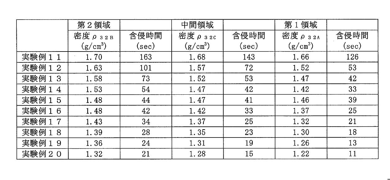
- the negative electrode 30 the density [rho 32B of the second region 32B, the density of the intermediate region 32C [rho 32C, and experimental examples of the density [rho 32A of the first region 32A is as follows.
- the following values are examples of average values of each density when graphite is used as the negative electrode active material, and the preferable range of each density varies depending on the type of the negative electrode active material and the like.
- the impregnation time is faster in the low density region in the high density region and the low density region of the positive electrode mixture layer and the negative electrode mixture layer. That is, the density [rho 22A and [rho 32A is lower than the density [rho 22C and [rho 32C, by the density [rho 22C and [rho 32C to form a lower-density pattern than the density [rho 22B and [rho 32B, liquid injection provided in the sealing plate 15
- the non-aqueous electrolyte solution injected from the portion 16 can smoothly move toward the bottom portion of the can on the opposite side of the injection portion. In other words, it means that the non-aqueous electrolyte solution can be evenly distributed throughout the electrode body.
- the outer can As described above, according to the non-aqueous electrolyte secondary battery 10 having the above configuration and having an electrode body 11 in which a plurality of positive electrodes and a plurality of negative electrodes are alternately laminated one by one via a separator, the outer can.
- the non-aqueous electrolyte solution is injected into the inside of 14, the entire electrode body 11 can be impregnated with the non-aqueous electrolyte solution, and the non-aqueous electrolyte solution can be evenly distributed over the entire electrode body 11. is there.
- the non-aqueous electrolyte solution is pushed out of the electrode body 11 due to the expansion of the electrode body 11 due to the charging and discharging of the battery, but the positive electrode body 11 and the negative electrode body 30 are alternately laminated one by one via the separator 40. Since it has a structure, the permeability of the non-aqueous electrolyte solution is better than that of the wound electrode body. That is, the non-aqueous electrolytic solution permeates from the top, bottom, left, and right of the electrode body 11.
- the impregnation property of the non-aqueous electrolyte solution into the electrode body 11 is greatly improved by the synergistic effect of the density pattern of the mixture layer and the laminated structure of the electrode body 11, so that the electrode body 11 is inside the electrode body. It is possible to suppress the performance deterioration caused by the variation in the amount of the non-aqueous electrolyte solution in.
- the design of the above embodiment can be appropriately changed as long as the object of the present disclosure is not impaired.
- the electrode body 11 including the first electrode group 11A and the second electrode group 11B is illustrated, but the electrode body 11 does not have to be divided into a plurality of electrode groups.
- the mixture layer having the above density pattern is formed only on a part of the plurality of positive electrodes 20 or only a part of the plurality of negative electrodes 30.
- Non-aqueous electrolyte secondary battery 11
- Electrode body 11A 1st electrode group 11B 2nd electrode group 12
- Positive electrode terminal 13
- Negative electrode terminal 14 Exterior can 15
- Seal plate 16 Liquid injection part 17
- Gas discharge valve 18
- Current cutoff mechanism 20
- Positive electrode 21
- Positive electrode Core body 22
- Positive electrode mixture layer 22A 1st area 22B 2nd area 22C
- Positive electrode tab 30
- Negative electrode Negative electrode core 32
- Negative electrode mixture layer 33
- Negative electrode tab 40
- Metal foil 51 51 Exposed part
Landscapes
- Chemical & Material Sciences (AREA)
- Chemical Kinetics & Catalysis (AREA)
- Electrochemistry (AREA)
- General Chemical & Material Sciences (AREA)
- Engineering & Computer Science (AREA)
- Manufacturing & Machinery (AREA)
- Materials Engineering (AREA)
- Secondary Cells (AREA)
- Battery Electrode And Active Subsutance (AREA)
- Sealing Battery Cases Or Jackets (AREA)
- Filling, Topping-Up Batteries (AREA)
Abstract
Description
正極20は、正極芯体21の表面のうち正極タブ23を除く部分(以下、「基部」とする)の全域に正極合材層22が形成された構造を有する。正極芯体21には、アルミニウムなどの電池作動電圧範囲で安定な金属の箔、当該金属を表層に配置したフィルム等を用いることができる。正極芯体21の厚みは、例えば5μm~20μmであり、好ましくは8μm~15μmである。正極芯体21の基部は正面視四角形状を有し、当該四角形の一辺から正極タブ23が突出している。一般的には、1枚の金属箔を加工して基部と正極タブ23が一体成形された正極芯体21が得られる。
密度ρ22Aは密度ρ22Cより低く、密度ρ22Cは密度ρ22Bより低い。正極合材層22にこのような密度パターンを形成することで、封口板15に設けられた注液部16から非水電解液を注液する際に、電極体11の全体にまんべんなく非水電解液を行き渡らせることが可能となる。
負極30は、負極芯体31の表面のうち負極タブ33を除く部分である基部の全域に負極合材層32が形成された構造を有する。負極芯体31には、銅などの電池作動電圧範囲で安定な金属の箔、当該金属を表層に配置したフィルム等を用いることができる。負極芯体31の厚みは、例えば3μm~15μmであり、好ましくは5μm~10μmである。正極20の場合と同様に、負極芯体31の基部は正面視四角形状を有し、当該四角形の一辺から負極タブ33が突出している。
負極合材層32の密度は、段階的に変化してもよいが、好ましくは負極合材層32の上端から下端に向かって徐々に低下する。
第2領域22Bの密度ρ22Bを3.72g/cm3、中間領域22Cの密度ρ22Cを3.62g/cm3、第1領域22Aの密度ρ22Aを3.52g/cm3となるように正極20を作製した。
第2領域22Bの密度ρ22Bを3.67g/cm3、中間領域22Cの密度ρ22Cを3.57g/cm3、第1領域22Aの密度ρ22Aを3.47g/cm3となるように正極20を作製した。
第2領域22Bの密度ρ22Bを3.62g/cm3、中間領域22Cの密度ρ22Cを3.52g/cm3、第1領域22Aの密度ρ22Aを3.42g/cm3となるように正極20を作製した。
第2領域22Bの密度ρ22Bを3.59g/cm3、中間領域22Cの密度ρ22Cを3.57g/cm3、第1領域22Aの密度ρ22Aを3.55g/cm3となるように正極20を作製した。
第2領域22Bの密度ρ22Bを3.57g/cm3、中間領域22Cの密度ρ22Cを3.47g/cm3、第1領域22Aの密度ρ22Aを3.37g/cm3となるように正極20を作製した。
第2領域22Bの密度ρ22Bを3.52g/cm3、中間領域22Cの密度ρ22Cを3.42g/cm3、第1領域22Aの密度ρ22Aを3.32g/cm3となるように正極20を作製した。
第2領域22Bの密度ρ22Bを3.44g/cm3、中間領域22Cの密度ρ22Cを3.34g/cm3、第1領域22Aの密度ρ22Aを3.23g/cm3となるように正極20を作製した。
第2領域22Bの密度ρ22Bを3.37g/cm3、中間領域22Cの密度ρ22Cを3.27g/cm3、第1領域22Aの密度ρ22Aを3.16g/cm3となるように正極20を作製した。
第2領域22Bの密度ρ22Bを3.30g/cm3、中間領域22Cの密度ρ22Cを3.20g/cm3、第1領域22Aの密度ρ22Aを3.08g/cm3となるように正極20を作製した。
第2領域22Bの密度ρ22Bを3.23g/cm3、中間領域22Cの密度ρ22Cを3.13g/cm3、第1領域22Aの密度ρ22Aを3.01g/cm3となるように正極20を作製した。
第2領域32Bの密度ρ32Bを1.70g/cm3、中間領域32Cの密度ρ32Cを1.68g/cm3、第1領域32Aの密度ρ32Aを1.66g/cm3となるように負極30を作製した。
第2領域32Bの密度ρ32Bを1.63g/cm3、中間領域32Cの密度ρ32Cを1.57g/cm3、第1領域32Aの密度ρ32Aを1.52g/cm3となるように負極30を作製した。
第2領域32Bの密度ρ32Bを1.58g/cm3、中間領域32Cの密度ρ32Cを1.52g/cm3、第1領域32Aの密度ρ32Aを1.47g/cm3となるように負極30を作製した。
第2領域32Bの密度ρ32Bを1.53g/cm3、中間領域32Cの密度ρ32Cを1.47g/cm3、第1領域32Aの密度ρ32Aを1.42g/cm3となるように負極30を作製した。
第2領域32Bの密度ρ32Bを1.48g/cm3、中間領域32Cの密度ρ32Cを1.47g/cm3、第1領域32Aの密度ρ32Aを1.46g/cm3となるように負極30を作製した。
第2領域32Bの密度ρ32Bを1.48g/cm3、中間領域32Cの密度ρ32Cを1.42g/cm3、第1領域32Aの密度ρ32Aを1.37g/cm3となるように負極30を作製した。
第2領域32Bの密度ρ32Bを1.43g/cm3、中間領域32Cの密度ρ32Cを1.37g/cm3、第1領域32Aの密度ρ32Aを1.32g/cm3となるように負極30を作製した。
第2領域32Bの密度ρ32Bを1.39g/cm3、中間領域32Cの密度ρ32Cを1.35g/cm3、第1領域32Aの密度ρ32Aを1.30g/cm3となるように負極30を作製した。
第2領域32Bの密度ρ32Bを1.36g/cm3、中間領域32Cの密度ρ32Cを1.31g/cm3、第1領域32Aの密度ρ32Aを1.26g/cm3となるように負極30を作製した。
第2領域32Bの密度ρ32Bを1.32g/cm3、中間領域32Cの密度ρ32Cを1.28g/cm3、第1領域32Aの密度ρ32Aを1.22g/cm3となるように負極30を作製した。
実験例1~20の正極20と負極30について、非水電解液の含侵速度の測定を行った。測定方法は、圧縮後の正極板に定量(1μml)の非水電解液を垂らして、完全に染み込むまでの時間を含侵時間としてストップウオッチで計測した。これらの結果を表1と表2に示す。

11 電極体
11A 第1の電極群
11B 第2の電極群
12 正極端子
13 負極端子
14 外装缶
15 封口板
16 注液部
17 ガス排出弁
18 電流遮断機構
20 正極
21 正極芯体
22 正極合材層
22A 第1領域
22B 第2領域
22C 中間領域
23 正極タブ
30 負極
31 負極芯体
32 負極合材層
33 負極タブ
40 セパレータ
50 金属箔
51 露出部
Claims (3)
- 複数の正極と複数の負極がセパレータを介して1枚ずつ交互に積層されてなる電極体と、
非水電解液と、
前記電極体及び前記非水電解液を収容する外装体と、
を備えた非水電解質二次電池であって、
前記外装体には、前記非水電解液を注液するための注液部が設けられ、
前記複数の正極は、正極芯体と、前記正極芯体の表面に形成された正極合材層とを含み、
前記複数の負極は、負極芯体と、前記負極芯体の表面に形成された負極合材層とを含み、
前記正極合材層及び前記負極合材層の少なくとも一方において、前記注液部から離れた第1領域の密度は、前記注液部に近接する第2領域の密度よりも低い、非水電解質二次電池。 - 前記外装体は、有底角筒状の外装缶と、前記外装缶の開口部を塞ぐ封口板とを含み、
前記注液部は、前記封口板に設けられ、
前記封口板側から前記外装缶の底部側に向かって前記正極合材層及び前記負極合材層の少なくとも一方を三等分し、前記封口板側から順に、前記第2領域、中間領域、及び前記第1領域と定義した場合に、当該各領域の密度は、前記第2領域の密度>前記中間領域の密度>前記第1領域の密度の関係を満たす、請求項1に記載の非水電解質二次電池。 - 複数の正極と複数の負極がセパレータを介して1枚ずつ交互に積層されてなる電極体と、非水電解液と、外装体とを備えた非水電解質二次電池の製造方法であって、
正極芯体の表面に前記正極合材層を形成して前記正極を作製する工程と、
負極芯体の表面に前記負極合材層を形成して前記負極を作製する工程と、
前記複数の正極及び前記複数の負極を用いて前記電極体を作製する工程と、
前記外装体の内部に前記電極体を収容した後、前記非水電解液を注液する工程と、
を含み、
前記正極合材層及び前記負極合材層を形成する少なくとも一方の工程において、合材層の第1の端部側に位置する領域の密度が、前記第1の端部と反対側の第2の端部側に位置する領域の密度よりも低くなるように合材層を形成し、
前記非水電解液を注液する工程では、前記第2の端部側から前記外装体の内部に前記非水電解液を注液する、非水電解質二次電池の製造方法。
Priority Applications (4)
| Application Number | Priority Date | Filing Date | Title |
|---|---|---|---|
| JP2021561291A JP7569801B2 (ja) | 2019-11-29 | 2020-11-12 | 非水電解質二次電池、及び非水電解質二次電池の製造方法 |
| US17/779,309 US20220399601A1 (en) | 2019-11-29 | 2020-11-12 | Non-aqueous electrolyte secondary cell and method for manufacturing non-aqueous electrolyte secondary cell |
| EP20892761.6A EP4068416A4 (en) | 2019-11-29 | 2020-11-12 | NON-AQUEOUS ELECTROLYTE ACCUMULATOR AND METHOD OF MANUFACTURING IT |
| CN202080082780.2A CN114762164B (zh) | 2019-11-29 | 2020-11-12 | 非水电解质二次电池、及非水电解质二次电池的制造方法 |
Applications Claiming Priority (2)
| Application Number | Priority Date | Filing Date | Title |
|---|---|---|---|
| JP2019216920 | 2019-11-29 | ||
| JP2019-216920 | 2019-11-29 |
Publications (1)
| Publication Number | Publication Date |
|---|---|
| WO2021106593A1 true WO2021106593A1 (ja) | 2021-06-03 |
Family
ID=76130207
Family Applications (1)
| Application Number | Title | Priority Date | Filing Date |
|---|---|---|---|
| PCT/JP2020/042220 Ceased WO2021106593A1 (ja) | 2019-11-29 | 2020-11-12 | 非水電解質二次電池、及び非水電解質二次電池の製造方法 |
Country Status (5)
| Country | Link |
|---|---|
| US (1) | US20220399601A1 (ja) |
| EP (1) | EP4068416A4 (ja) |
| JP (1) | JP7569801B2 (ja) |
| CN (1) | CN114762164B (ja) |
| WO (1) | WO2021106593A1 (ja) |
Cited By (2)
| Publication number | Priority date | Publication date | Assignee | Title |
|---|---|---|---|---|
| EP4366016A4 (en) * | 2021-06-28 | 2025-06-18 | Panasonic Energy Co., Ltd. | SECONDARY BATTERY WITH NON-AQUEOUS ELECTROLYTE |
| EP4510209A4 (en) * | 2022-09-28 | 2026-01-21 | Contemporary Amperex Technology Co Ltd | NEGATIVE ELECTRODE SHEET AND BATTERY MADE FROM IT |
Citations (6)
| Publication number | Priority date | Publication date | Assignee | Title |
|---|---|---|---|---|
| JP2000090980A (ja) * | 1998-09-10 | 2000-03-31 | Sanyo Electric Co Ltd | リチウム二次電池 |
| JP2001176558A (ja) | 1999-12-20 | 2001-06-29 | Toshiba Corp | 非水電解液二次電池 |
| JP2006278182A (ja) * | 2005-03-30 | 2006-10-12 | Sanyo Electric Co Ltd | 非水電解質二次電池とその製造方法 |
| JP2016058181A (ja) * | 2014-09-08 | 2016-04-21 | トヨタ自動車株式会社 | 非水系二次電池用電極板の製造方法 |
| WO2018021214A1 (ja) * | 2016-07-28 | 2018-02-01 | 三洋電機株式会社 | 二次電池及びその製造方法 |
| JP2018137187A (ja) | 2017-02-23 | 2018-08-30 | パナソニックIpマネジメント株式会社 | リチウムイオン二次電池およびその製造方法 |
Family Cites Families (8)
| Publication number | Priority date | Publication date | Assignee | Title |
|---|---|---|---|---|
| JP2004207253A (ja) * | 1997-04-23 | 2004-07-22 | Japan Storage Battery Co Ltd | 非水電解質二次電池 |
| EP0967672B1 (en) * | 1997-04-23 | 2005-06-29 | Japan Storage Battery Co., Ltd. | Electrode and battery |
| JP4649113B2 (ja) * | 2004-01-20 | 2011-03-09 | 株式会社東芝 | 非水電解質二次電池 |
| KR20120095122A (ko) * | 2011-02-18 | 2012-08-28 | 주식회사 엘지화학 | 전극 조립체 및 이를 이용한 이차 전지 |
| JP5957927B2 (ja) * | 2012-02-09 | 2016-07-27 | 日本電気株式会社 | 電池の製造方法及び電池の製造装置 |
| JP6017873B2 (ja) * | 2012-07-27 | 2016-11-02 | トヨタ自動車株式会社 | 密閉型電池 |
| JP5664608B2 (ja) * | 2012-08-06 | 2015-02-04 | トヨタ自動車株式会社 | 電池 |
| JP2014075187A (ja) * | 2012-10-02 | 2014-04-24 | Toyota Industries Corp | 蓄電装置の製造方法及び電極組立体 |
-
2020
- 2020-11-12 US US17/779,309 patent/US20220399601A1/en active Pending
- 2020-11-12 EP EP20892761.6A patent/EP4068416A4/en active Pending
- 2020-11-12 WO PCT/JP2020/042220 patent/WO2021106593A1/ja not_active Ceased
- 2020-11-12 CN CN202080082780.2A patent/CN114762164B/zh active Active
- 2020-11-12 JP JP2021561291A patent/JP7569801B2/ja active Active
Patent Citations (6)
| Publication number | Priority date | Publication date | Assignee | Title |
|---|---|---|---|---|
| JP2000090980A (ja) * | 1998-09-10 | 2000-03-31 | Sanyo Electric Co Ltd | リチウム二次電池 |
| JP2001176558A (ja) | 1999-12-20 | 2001-06-29 | Toshiba Corp | 非水電解液二次電池 |
| JP2006278182A (ja) * | 2005-03-30 | 2006-10-12 | Sanyo Electric Co Ltd | 非水電解質二次電池とその製造方法 |
| JP2016058181A (ja) * | 2014-09-08 | 2016-04-21 | トヨタ自動車株式会社 | 非水系二次電池用電極板の製造方法 |
| WO2018021214A1 (ja) * | 2016-07-28 | 2018-02-01 | 三洋電機株式会社 | 二次電池及びその製造方法 |
| JP2018137187A (ja) | 2017-02-23 | 2018-08-30 | パナソニックIpマネジメント株式会社 | リチウムイオン二次電池およびその製造方法 |
Non-Patent Citations (1)
| Title |
|---|
| See also references of EP4068416A4 |
Cited By (2)
| Publication number | Priority date | Publication date | Assignee | Title |
|---|---|---|---|---|
| EP4366016A4 (en) * | 2021-06-28 | 2025-06-18 | Panasonic Energy Co., Ltd. | SECONDARY BATTERY WITH NON-AQUEOUS ELECTROLYTE |
| EP4510209A4 (en) * | 2022-09-28 | 2026-01-21 | Contemporary Amperex Technology Co Ltd | NEGATIVE ELECTRODE SHEET AND BATTERY MADE FROM IT |
Also Published As
| Publication number | Publication date |
|---|---|
| JP7569801B2 (ja) | 2024-10-18 |
| EP4068416A1 (en) | 2022-10-05 |
| JPWO2021106593A1 (ja) | 2021-06-03 |
| US20220399601A1 (en) | 2022-12-15 |
| CN114762164B (zh) | 2025-09-02 |
| EP4068416A4 (en) | 2023-01-25 |
| CN114762164A (zh) | 2022-07-15 |
Similar Documents
| Publication | Publication Date | Title |
|---|---|---|
| RU2622108C1 (ru) | Литиевый электрод и содержащая его литиевая аккумуляторная батарея | |
| CN113632256B (zh) | 二次电池 | |
| KR102790285B1 (ko) | 음극의 전리튬화 방법 및 이로부터 제조된 음극 | |
| CN110970669B (zh) | 非水电解质二次电池 | |
| CN112335071B (zh) | 电池用电极、电池以及电池用电极的制造方法 | |
| CN110970653B (zh) | 非水电解质二次电池 | |
| JP7621246B2 (ja) | 極板、非水電解質二次電池、及び極板の製造方法 | |
| JP2014179240A (ja) | 正極及び電池 | |
| CN112204768B (zh) | 非水电解质二次电池 | |
| CN113614943B (zh) | 二次电池 | |
| US20220037643A1 (en) | Nonaqueous electrolyte secondary battery negative electrode and nonaqueous electrolyte secondary battery | |
| CN114830370B (zh) | 二次电池用电极及二次电池 | |
| JP7429706B2 (ja) | 組電池 | |
| US20080113260A1 (en) | Prismatic nonaqueous electrolyte secondary battery and method for manufacturing the same | |
| CN112204767B (zh) | 非水电解质二次电池 | |
| CN117178404A (zh) | 非水电解质二次电池 | |
| JP7569801B2 (ja) | 非水電解質二次電池、及び非水電解質二次電池の製造方法 | |
| JP7336680B2 (ja) | 二次電池 | |
| WO2024225018A1 (ja) | 二次電池用正極および二次電池 | |
| WO2022196445A1 (ja) | 非水電解質二次電池 | |
| CN113412547A (zh) | 正极及二次电池 | |
| EP4704166A1 (en) | Positive electrode for secondary battery, and secondary battery | |
| WO2024225019A1 (ja) | 二次電池用正極および二次電池 | |
| WO2022176629A1 (ja) | 非水電解質二次電池 |
Legal Events
| Date | Code | Title | Description |
|---|---|---|---|
| 121 | Ep: the epo has been informed by wipo that ep was designated in this application |
Ref document number: 20892761 Country of ref document: EP Kind code of ref document: A1 |
|
| ENP | Entry into the national phase |
Ref document number: 2021561291 Country of ref document: JP Kind code of ref document: A |
|
| NENP | Non-entry into the national phase |
Ref country code: DE |
|
| ENP | Entry into the national phase |
Ref document number: 2020892761 Country of ref document: EP Effective date: 20220629 |
|
| WWG | Wipo information: grant in national office |
Ref document number: 202080082780.2 Country of ref document: CN |