WO2021106837A1 - 端末装置、基地局装置および通信方法 - Google Patents
端末装置、基地局装置および通信方法 Download PDFInfo
- Publication number
- WO2021106837A1 WO2021106837A1 PCT/JP2020/043587 JP2020043587W WO2021106837A1 WO 2021106837 A1 WO2021106837 A1 WO 2021106837A1 JP 2020043587 W JP2020043587 W JP 2020043587W WO 2021106837 A1 WO2021106837 A1 WO 2021106837A1
- Authority
- WO
- WIPO (PCT)
- Prior art keywords
- signal
- base station
- signal waveform
- terminal device
- information
- Prior art date
- Legal status (The legal status is an assumption and is not a legal conclusion. Google has not performed a legal analysis and makes no representation as to the accuracy of the status listed.)
- Ceased
Links
Images





Classifications
-
- H—ELECTRICITY
- H04—ELECTRIC COMMUNICATION TECHNIQUE
- H04L—TRANSMISSION OF DIGITAL INFORMATION, e.g. TELEGRAPHIC COMMUNICATION
- H04L27/00—Modulated-carrier systems
- H04L27/0008—Modulated-carrier systems arrangements for allowing a transmitter or receiver to use more than one type of modulation
-
- H—ELECTRICITY
- H04—ELECTRIC COMMUNICATION TECHNIQUE
- H04W—WIRELESS COMMUNICATION NETWORKS
- H04W72/00—Local resource management
- H04W72/20—Control channels or signalling for resource management
- H04W72/23—Control channels or signalling for resource management in the downlink direction of a wireless link, i.e. towards a terminal
-
- H—ELECTRICITY
- H04—ELECTRIC COMMUNICATION TECHNIQUE
- H04L—TRANSMISSION OF DIGITAL INFORMATION, e.g. TELEGRAPHIC COMMUNICATION
- H04L27/00—Modulated-carrier systems
- H04L27/26—Systems using multi-frequency codes
- H04L27/2601—Multicarrier modulation systems
- H04L27/2602—Signal structure
-
- H—ELECTRICITY
- H04—ELECTRIC COMMUNICATION TECHNIQUE
- H04L—TRANSMISSION OF DIGITAL INFORMATION, e.g. TELEGRAPHIC COMMUNICATION
- H04L27/00—Modulated-carrier systems
- H04L27/26—Systems using multi-frequency codes
- H04L27/2601—Multicarrier modulation systems
- H04L27/2626—Arrangements specific to the transmitter only
- H04L27/2627—Modulators
- H04L27/2628—Inverse Fourier transform modulators, e.g. inverse fast Fourier transform [IFFT] or inverse discrete Fourier transform [IDFT] modulators
-
- H—ELECTRICITY
- H04—ELECTRIC COMMUNICATION TECHNIQUE
- H04L—TRANSMISSION OF DIGITAL INFORMATION, e.g. TELEGRAPHIC COMMUNICATION
- H04L27/00—Modulated-carrier systems
- H04L27/26—Systems using multi-frequency codes
- H04L27/2601—Multicarrier modulation systems
- H04L27/2626—Arrangements specific to the transmitter only
- H04L27/2627—Modulators
- H04L27/2634—Inverse fast Fourier transform [IFFT] or inverse discrete Fourier transform [IDFT] modulators in combination with other circuits for modulation
- H04L27/2636—Inverse fast Fourier transform [IFFT] or inverse discrete Fourier transform [IDFT] modulators in combination with other circuits for modulation with FFT or DFT modulators, e.g. standard single-carrier frequency-division multiple access [SC-FDMA] transmitter or DFT spread orthogonal frequency division multiplexing [DFT-SOFDM]
-
- H—ELECTRICITY
- H04—ELECTRIC COMMUNICATION TECHNIQUE
- H04L—TRANSMISSION OF DIGITAL INFORMATION, e.g. TELEGRAPHIC COMMUNICATION
- H04L27/00—Modulated-carrier systems
- H04L27/26—Systems using multi-frequency codes
- H04L27/2601—Multicarrier modulation systems
- H04L27/2626—Arrangements specific to the transmitter only
- H04L27/2627—Modulators
- H04L27/264—Pulse-shaped multi-carrier, i.e. not using rectangular window
-
- H—ELECTRICITY
- H04—ELECTRIC COMMUNICATION TECHNIQUE
- H04L—TRANSMISSION OF DIGITAL INFORMATION, e.g. TELEGRAPHIC COMMUNICATION
- H04L27/00—Modulated-carrier systems
- H04L27/26—Systems using multi-frequency codes
- H04L27/2601—Multicarrier modulation systems
- H04L27/2647—Arrangements specific to the receiver only
- H04L27/2649—Demodulators
- H04L27/265—Fourier transform demodulators, e.g. fast Fourier transform [FFT] or discrete Fourier transform [DFT] demodulators
-
- H—ELECTRICITY
- H04—ELECTRIC COMMUNICATION TECHNIQUE
- H04L—TRANSMISSION OF DIGITAL INFORMATION, e.g. TELEGRAPHIC COMMUNICATION
- H04L27/00—Modulated-carrier systems
- H04L27/26—Systems using multi-frequency codes
- H04L27/2601—Multicarrier modulation systems
- H04L27/2647—Arrangements specific to the receiver only
- H04L27/2649—Demodulators
- H04L27/26524—Fast Fourier transform [FFT] or discrete Fourier transform [DFT] demodulators in combination with other circuits for demodulation
- H04L27/26526—Fast Fourier transform [FFT] or discrete Fourier transform [DFT] demodulators in combination with other circuits for demodulation with inverse FFT [IFFT] or inverse DFT [IDFT] demodulators, e.g. standard single-carrier frequency-division multiple access [SC-FDMA] receiver or DFT spread orthogonal frequency division multiplexing [DFT-SOFDM]
-
- H—ELECTRICITY
- H04—ELECTRIC COMMUNICATION TECHNIQUE
- H04L—TRANSMISSION OF DIGITAL INFORMATION, e.g. TELEGRAPHIC COMMUNICATION
- H04L5/00—Arrangements affording multiple use of the transmission path
- H04L5/0001—Arrangements for dividing the transmission path
- H04L5/0003—Two-dimensional division
- H04L5/0005—Time-frequency
- H04L5/0007—Time-frequency the frequencies being orthogonal, e.g. OFDM(A) or DMT
-
- H—ELECTRICITY
- H04—ELECTRIC COMMUNICATION TECHNIQUE
- H04L—TRANSMISSION OF DIGITAL INFORMATION, e.g. TELEGRAPHIC COMMUNICATION
- H04L5/00—Arrangements affording multiple use of the transmission path
- H04L5/0001—Arrangements for dividing the transmission path
- H04L5/0003—Two-dimensional division
- H04L5/0005—Time-frequency
- H04L5/0007—Time-frequency the frequencies being orthogonal, e.g. OFDM(A) or DMT
- H04L5/001—Time-frequency the frequencies being orthogonal, e.g. OFDM(A) or DMT the frequencies being arranged in component carriers
-
- H—ELECTRICITY
- H04—ELECTRIC COMMUNICATION TECHNIQUE
- H04L—TRANSMISSION OF DIGITAL INFORMATION, e.g. TELEGRAPHIC COMMUNICATION
- H04L5/00—Arrangements affording multiple use of the transmission path
- H04L5/003—Arrangements for allocating sub-channels of the transmission path
- H04L5/0048—Allocation of pilot signals, i.e. of signals known to the receiver
- H04L5/005—Allocation of pilot signals, i.e. of signals known to the receiver of common pilots, i.e. pilots destined for multiple users or terminals
-
- H—ELECTRICITY
- H04—ELECTRIC COMMUNICATION TECHNIQUE
- H04L—TRANSMISSION OF DIGITAL INFORMATION, e.g. TELEGRAPHIC COMMUNICATION
- H04L5/00—Arrangements affording multiple use of the transmission path
- H04L5/003—Arrangements for allocating sub-channels of the transmission path
- H04L5/0053—Allocation of signalling, i.e. of overhead other than pilot signals
-
- H—ELECTRICITY
- H04—ELECTRIC COMMUNICATION TECHNIQUE
- H04W—WIRELESS COMMUNICATION NETWORKS
- H04W72/00—Local resource management
- H04W72/04—Wireless resource allocation
- H04W72/044—Wireless resource allocation based on the type of the allocated resource
- H04W72/0453—Resources in frequency domain, e.g. a carrier in FDMA
-
- H—ELECTRICITY
- H04—ELECTRIC COMMUNICATION TECHNIQUE
- H04W—WIRELESS COMMUNICATION NETWORKS
- H04W72/00—Local resource management
- H04W72/20—Control channels or signalling for resource management
- H04W72/23—Control channels or signalling for resource management in the downlink direction of a wireless link, i.e. towards a terminal
- H04W72/231—Control channels or signalling for resource management in the downlink direction of a wireless link, i.e. towards a terminal the control data signalling from the layers above the physical layer, e.g. RRC or MAC-CE signalling
-
- H—ELECTRICITY
- H04—ELECTRIC COMMUNICATION TECHNIQUE
- H04W—WIRELESS COMMUNICATION NETWORKS
- H04W72/00—Local resource management
- H04W72/20—Control channels or signalling for resource management
- H04W72/23—Control channels or signalling for resource management in the downlink direction of a wireless link, i.e. towards a terminal
- H04W72/232—Control channels or signalling for resource management in the downlink direction of a wireless link, i.e. towards a terminal the control data signalling from the physical layer, e.g. DCI signalling
-
- H—ELECTRICITY
- H04—ELECTRIC COMMUNICATION TECHNIQUE
- H04L—TRANSMISSION OF DIGITAL INFORMATION, e.g. TELEGRAPHIC COMMUNICATION
- H04L27/00—Modulated-carrier systems
- H04L27/26—Systems using multi-frequency codes
- H04L27/2601—Multicarrier modulation systems
- H04L27/2614—Peak power aspects
-
- H—ELECTRICITY
- H04—ELECTRIC COMMUNICATION TECHNIQUE
- H04W—WIRELESS COMMUNICATION NETWORKS
- H04W72/00—Local resource management
- H04W72/12—Wireless traffic scheduling
- H04W72/1263—Mapping of traffic onto schedule, e.g. scheduled allocation or multiplexing of flows
- H04W72/1273—Mapping of traffic onto schedule, e.g. scheduled allocation or multiplexing of flows of downlink data flows
Definitions
- This disclosure relates to terminal equipment, base station equipment and communication methods.
- LTE Long Term Evolution
- LTE-A Long Term Evolution
- LTE-A Pro Long Term Evolution Pro
- NR New Radio
- NRAT New Radio Access Technology
- EUTRA Evolved Universa LTErrestrial Radio Access
- FEUTRA Further EUTRA
- LTE includes LTE-A, LTE-A Pro, and EUTRA
- NR includes NRAT and FEUTRA.
- the base station device (base station) is also called eNodeB (evolved NodeB) in LTE and gNodeB in NR
- the terminal device (mobile station, mobile station device, terminal) is also called UE (User Equipment).
- LTE and NR are cellular communication systems in which a plurality of areas covered by base station devices are arranged in a cell shape. A single base station device may manage multiple cells.
- NR is RAT (Radio Access Technology), which is different from LTE, as a next-generation wireless access method for LTE.
- NR is an access technology that can support various use cases including eMMB (Enhanced mobile broadband), mMTC (Massive machine type communications) and URLLC (Ultra reliable and low latency communications).
- eMMB Enhanced mobile broadband
- mMTC Massive machine type communications
- URLLC Ultra reliable and low latency communications
- Non-Patent Document 1 A study on the utilization of millimeter waves in 3GPP is disclosed in, for example, Non-Patent Document 1.
- the signal waveform (Waveform) having a low PAPR Peak to Average Power RATio: peak to average power ratio
- PAPR Peak to Average Power RATio: peak to average power ratio
- CP-OFDM Cyclic Prefix-Orthogonal Frequency Division Multiplexing
- LTE and NR downlink communication has a problem that PAPR is large and it is difficult to satisfy the low PAPR required for millimeter waves.
- this disclosure proposes a mechanism that can meet the requirements of PAPR in downlink communication.
- a terminal device has a control unit.
- the control unit uses information on a signal waveform used for downlink communication with the base station device among a plurality of signal waveforms including a single carrier signal, and uses a predetermined signal waveform among the plurality of signal waveforms.
- the information to be transmitted is acquired from the base station apparatus. Based on the information, the control unit performs the downlink communication with the base station apparatus using the signal waveform used.
- a plurality of components having substantially the same functional configuration may be distinguished by adding different alphabets after the same reference numerals.
- a plurality of configurations having substantially the same functional configuration are distinguished as required by the terminal device 2A and the terminal device 2B.
- only the same reference numerals are given.
- the terminal device 2A and the terminal device 2B it is simply referred to as the terminal device 2.
- High data RATe eMBB Mobile data offloading ⁇ Short-range high data RATe D2D communications ⁇ Vertical industry factory application ⁇ Broadband distribution network ⁇ IntegRATed access backhaul (IAB) ⁇ Factory automation / Industrial IoT (IIoT) ⁇ Augmented reality / virtual reality headsets and other high-end wearables -Intelligent Transport System (ITS) and V2X ⁇ Data center inter-rack connectivity ⁇ Smart grid automation ⁇ Radar / positioning
- the signal waveform (waveform) with a low PAPR Peak to Average Power RATio: peak to average power ratio
- PAPR Peak to Average Power RATio: peak to average power ratio
- a single carrier signal is known as a signal waveform having such a low PAPR.
- Low PAPR can be achieved by using a single carrier signal for wireless communication using millimeter waves.
- the multi-carrier signal has the following advantages as compared with the single-carrier signal. ⁇ Easy separation for multipath ⁇ Easy digital precoding for each frequency ⁇ Easy non-contiguous allocation of resources on the frequency axis
- the ease of separation for multipath especially affects the MIMO multi-number. Since the multi-carrier signal is easy to separate for multi-pass, the MIMO multiple number can be increased as compared with the single-carrier signal.
- the base station device Since the base station device is connected to a plurality of terminal devices, it is required to improve the frequency utilization efficiency even in the millimeter wave band. As described above, in downlink communication in the millimeter wave band, low PAPR and improvement of the efficiency of the entire system are required.
- Embodiment> ⁇ 2.1. Overview of communication system> Therefore, in the technique of the present disclosure, downlink communication is performed using one of a plurality of signal waveforms including a single carrier signal in order to realize low PAPR and improvement of the efficiency of the entire system. The outline of the technique of the present disclosure will be described with reference to FIG.
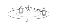
- FIG. 1 is a diagram for explaining an outline of the communication system according to the embodiment of the present disclosure.
- the communication system according to the present embodiment includes a base station device 1 and a plurality of terminal devices 2A and 2B.
- the base station device 1 determines a signal waveform to be used for downlink communication with the terminal device 2 from a plurality of signal waveforms including a single carrier signal. For example, the base station apparatus 1 determines that either the single carrier signal or the multicarrier signal is used for downlink communication.
- the multicarrier signal is, for example, CP-OFDM.
- examples of the single carrier signal include DFT-S-OFDM, SC-QAM, and Single carrier with zero padding / unique word.
- the base station device 1 determines, for example, a signal waveform to be used for each terminal device 2, and notifies the terminal device 2 of information regarding the determined signal waveform.
- the base station device 1 performs downlink communication with the terminal device 2 using the notified signal waveform.
- the base station device 1 selects a multicarrier signal and performs downlink communication S1 with respect to the terminal device 2A located closer to the center of the cell C. Further, the base station device 1 selects a single carrier signal and performs downlink communication S2 with respect to the terminal device 2B located closer to the edge of the cell C.
- the required transmission power is smaller than that of the cell edge, so that it is easy to secure the required transmission power even if the PAPR is high.
- the base station device 1 selects a multi-carrier signal for the terminal device 2A located closer to the center of the cell C, and selects a single carrier signal for the terminal device 2B located closer to the edge of the cell C. To do.
- the base station apparatus 1 allocates a single carrier signal for downlink communication in which low PAPR is strictly required, and a signal waveform other than the single carrier signal for downlink communication in which low PAPR is loosely required (here). Let's assign a multi-carrier signal). As a result, the base station apparatus 1 can realize low PAPR and improved efficiency of the entire system.
- the method for determining the signal waveform by the base station device 1 is not limited to this. Details of the method for determining the signal waveform by the base station apparatus 1 will be described later.
- the communication system according to the present embodiment includes a base station device 1 and a terminal device 2.
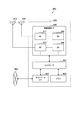
- FIG. 2 is a block diagram showing a configuration example of the base station device 1 according to the embodiment of the present disclosure.
- the base station apparatus 1 includes an upper layer processing unit 101, a control unit 103, a reception unit 105, a transmission unit 107, and a transmission / reception antenna 109.
- the base station device 1 can support one or more RATs (Radio Access Technology).
- base station equipment 1 may support both LTE and NR.
- a part or all of each part included in the base station apparatus 1 may be individually configured according to the RAT.
- the receiving unit 105 and the transmitting unit 107 are individually configured by LTE and NR.
- a part or all of each part included in the base station apparatus 1 shown in FIG. 2 may be individually configured according to a parameter set relating to a transmission signal.
- the radio receiver 1057 and radio transmitter 1077 may be individually configured depending on the set of parameters for the transmit signal.
- the upper layer processing unit 101 outputs downlink data (transport block) to the control unit 103.
- the upper layer processing unit 101 includes a medium access control (MAC) layer, a packet data integration protocol (PDCP) layer, a radio link control (RLC) layer, and a radio resource control (Radio). Resource Control: RRC) Performs layer processing. Further, the upper layer processing unit 101 generates control information for controlling the receiving unit 105 and the transmitting unit 107, and outputs the control information to the control unit 103.
- MAC medium access control
- PDCP packet data integration protocol
- RLC radio link control
- Radio Radio Resource Control
- the upper layer processing unit 101 performs processing and management related to RAT control, radio resource control, subframe setting, scheduling control, and / or CSI report control.
- the processing and management in the upper layer processing unit 101 are performed for each terminal device or common to the terminal devices connected to the base station device.
- the processing and management in the upper layer processing unit 101 may be performed only by the upper layer processing unit 101, or may be acquired from the upper node or another base station device. Further, the processing and management in the upper layer processing unit 101 may be performed individually according to the RAT. For example, the upper layer processing unit 101 individually performs processing and management in LTE and processing and management in NR.
- management related to RAT is performed. For example, in RAT control, LTE management and / or NR management is performed.
- Management of NR includes setting and processing parameter sets for transmitted signals in NR cells.
- the setting information in the own device is managed.
- downlink data transport block
- system information system information
- RRC message RRC parameter
- CE MAC control element
- the subframe setting in the upper layer processing unit 101 In the subframe setting in the upper layer processing unit 101, the subframe setting, the subframe pattern setting, the uplink downlink setting, the uplink reference UL-DL setting, and / or the downlink reference UL-DL setting are managed. ..
- the subframe setting in the upper layer processing unit 101 is also referred to as a base station subframe setting. Further, the subframe setting in the upper layer processing unit 101 can be determined based on the traffic amount of the uplink and the traffic amount of the downlink. Further, the subframe setting in the upper layer processing unit 101 can be determined based on the scheduling result of the scheduling control in the upper layer processing unit 101.
- the frequency, subframe, and physical channel to which the physical channel is assigned are based on the received channel state information, the estimated value of the propagation path input from the channel measurement unit 1059, the channel quality, and the like.
- the coding rate, modulation method, transmission power, etc. are determined.
- the control unit 103 generates control information (DCI format) based on the scheduling result of the scheduling control in the upper layer processing unit 101.
- the CSI report of the terminal device 2 is controlled.
- the terminal device 2 controls the settings related to the CSI reference resource to be assumed for calculating the CSI.
- the control unit 103 controls the receiving unit 105 and the transmitting unit 107 based on the control information from the upper layer processing unit 101.
- the control unit 103 generates control information for the upper layer processing unit 101 and outputs it to the upper layer processing unit 101.
- the control unit 103 inputs the decoded signal from the decoding unit 1051 and the channel estimation result from the channel measurement unit 1059.
- the control unit 103 outputs the coded signal to the coding unit 1071. Further, the control unit 103 is used to control all or a part of the base station apparatus 1.
- control unit 103 determines a signal waveform (hereinafter, also referred to as a signal waveform used) used for downlink communication with the terminal device 2 among the single carrier signal and the multicarrier signal.
- the control unit 103 controls the transmission unit 107 to notify the terminal device 2 of information regarding the signal waveform used by using a predetermined signal waveform (for example, a single carrier signal).
- the control unit 103 controls the transmission unit 107 to perform downlink communication with the terminal device 2 using the notified signal waveform. The details of the processing by the control unit 103 will be described later.
- the receiving unit 105 receives the signal transmitted from the terminal device 2 via the transmitting / receiving antenna 109 according to the control from the control unit 103, further performs reception processing such as separation, demodulation, and decoding, and the received information. Is output to the control unit 103.
- the reception process in the receiving unit 105 is performed based on a predetermined setting or a setting notified by the base station device 1 to the terminal device 2.
- the receiving unit 105 includes a decoding unit 1051, a demodulation unit 1053, a multiplex separation unit 1055, a wireless reception unit 1057, and a channel measurement unit 1059.
- the radio receiver 1057 converts the uplink signal received via the transmission / reception antenna 109 to an intermediate frequency (down-conversion), removes unnecessary frequency components, and maintains an appropriate signal level. Control of amplification level, orthogonal demodulation based on in-phase and orthogonal components of the received signal, conversion of analog and digital signals, removal of Guard Interval (GI), and / or Fast Fourier Transform. The frequency domain signal is extracted by Transform: FFT).
- the multiplex separation unit 1055 separates the uplink channel such as PUCCH or PUSCH and / or the uplink reference signal from the signal input from the radio reception unit 1057.
- the multiplex separation unit 1055 outputs an uplink reference signal to the channel measurement unit 1059.
- the multiple separation unit 1055 compensates the propagation path for the uplink channel from the estimated value of the propagation path input from the channel measurement unit 1059.
- the demodulator 1053 uses modulation methods such as BPSK (Binary Phase Shift Keying), ⁇ / 2BPSK, QPSK (Quadrature Phase shift Keying), 16QAM (Quadrature Amplitude Modulation), 64QAM, and 256QAM for the modulation symbols of the uplink channel. Use to demodulate the received signal.
- the demodulation unit 1053 separates and demodulates the MIMO-multiplexed uplink channels.
- the decoding unit 1051 performs decoding processing on the coded bits of the demodulated uplink channel.
- the decoded uplink data and / or uplink control information is output to the control unit 103.
- the decoding unit 1051 performs a decoding process on the PUSCH for each transport block.
- the channel measurement unit 1059 measures the estimated value of the propagation path and / or the quality of the channel from the uplink reference signal input from the multiplex separation unit 1055, and outputs the measurement to the multiplex separation unit 1055 and / or the control unit 103.
- the channel measurement unit 1059 uses UL-DMRS to measure the estimated value of the propagation path for performing propagation path compensation for PUCCH or PUSCH, and SRS to measure the quality of the channel in the uplink.
- the transmission unit 107 performs transmission processing such as coding, modulation, and multiplexing on the downlink control information and downlink data input from the upper layer processing unit 101 according to the control from the control unit 103. For example, the transmitter 107 generates and multiplexes PHICH, PDCCH, EPDCCH, PDSCH, and downlink reference signals to generate a transmit signal. The transmission process in the transmission unit 107 is based on a predetermined setting, a setting notified by the base station device 1 to the terminal device 2, or a setting notified through PDCCH or EPDCCH transmitted in the same subframe. Will be done.
- the transmission unit 107 includes a coding unit 1071, a modulation unit 1073, a multiplexing unit 1075, a radio transmission unit 1077, and a downlink reference signal generation unit 1079.
- the coding unit 1071 uses a predetermined code such as block coding, convolution coding, turbo coding, etc. for the HARQ indicator (HARQ-ACK), downlink control information, and downlink data input from the control unit 103. Encoding is performed using the conversion method.
- the modulation unit 1073 modulates the coding bits input from the coding unit 1071 by a predetermined modulation method such as BPSK, ⁇ / 2BPSK, QPSK, 16QAM, 64QAM, 256QAM.
- the downlink reference signal generation unit 1079 generates a downlink reference signal based on a physical cell identifier (PCI), an RRC parameter set in the terminal device 2, and the like.
- PCI physical cell identifier
- the multiplexing unit 1075 multiplexes the modulation symbols of each channel and the downlink reference signal and arranges them in a predetermined resource element.
- the radio transmission unit 1077 converts the signal from the multiplexing unit 1075 into a time region signal by an inverse fast Fourier transform (IFFT), adds a guard interval, and generates a baseband digital signal. Processes such as conversion to analog signal, orthogonal modulation, conversion from intermediate frequency signal to high frequency signal (up convert), removal of excess frequency components, power amplification, etc. are performed to generate a transmission signal. ..
- the transmission signal output by the wireless transmission unit 1077 is transmitted from the transmission / reception antenna 109.
- the wireless transmission unit 1077 can support a plurality of downlink signal waveforms.
- the details of the radio transmission unit 1077 in the base station apparatus 1 that supports both the first signal waveform (multicarrier signal) and the second signal waveform (single carrier signal) will be described with reference to FIGS. 3 to 5.
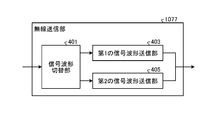
- FIG. 3 is a block diagram showing a configuration example of the wireless transmission unit 1077.
- the wireless transmission unit 1077 includes a signal waveform switching unit 401, a first signal waveform transmission unit 403, and a second signal waveform transmission unit 405.
- the signal waveform switching unit 401 switches whether the downlink communication to be transmitted is the first signal waveform or the second signal waveform according to a predetermined condition or situation.
- the downlink communication to be transmitted is the first signal waveform
- the downlink communication is transmitted by the first signal waveform transmission unit 403.
- the downlink communication is processed by the second signal waveform transmission unit 405.
- the switching conditions and situations in the signal waveform switching unit 401 will be described later.
- the signal waveform switching unit is also referred to as a signal waveform control unit. Further, in FIG. 3, the first signal waveform transmission unit 403 and the second signal waveform transmission unit 405 are described as different processing units, but only a part of the transmission processing is switched as one processing unit. It may be done.
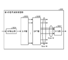
- FIG. 4 is a block diagram showing a configuration example of the first signal waveform transmission unit 403.
- the first signal waveform transmission unit 403 performs transmission processing on the downlink channel and the signal transmitted by CP-OFDM as the signal waveform of the uplink communication.
- the first signal waveform transmission unit 403 includes an S / P unit 4031, an IDFT (Inverse Discrete Fourier Transform) unit 4033, a P / S unit 4035, and a CP insertion unit 4037.
- S / P unit 4031 an IDFT (Inverse Discrete Fourier Transform) unit 4033, a P / S unit 4035, and a CP insertion unit 4037.
- IDFT Inverse Discrete Fourier Transform
- the S / P unit 4031 converts the input serial signal into a size M parallel signal.
- the size M is determined depending on the size of resources in the frequency domain used for downlink communication.
- the parallel signal of size M is input to the IDFT unit 4033 so as to correspond to a predetermined frequency region.
- the IDFT unit 4033 performs an inverse Fourier transform process on a parallel signal of size N.
- the Fourier transform process can be IFFT (Inverse Fast Fourier Transform) process.
- the P / S unit 4035 converts a size N parallel signal into a serial signal.
- the CP insertion unit 4037 inserts a predetermined CP for each OFDM symbol.
- FIG. 5 is a block diagram showing a configuration example of the second signal waveform transmission unit 405.
- the second signal waveform transmission unit 405 performs transmission processing on the downlink channel and the signal transmitted by, for example, SC-FDMA as the signal waveform of the downlink communication.
- the second signal waveform transmission unit 405 includes a DFT unit 4051, an IDFT (Inverse Discrete Fourier Transform) unit 4053, a P / S unit 4055, and a CP insertion unit 4057.
- the DFT unit 4051 performs DFT conversion into a parallel signal of size M.
- the size M is determined depending on the size of resources in the frequency domain used for downlink communication.
- the parallel signal of size M is input to the IDFT unit 4053 so as to correspond to a predetermined frequency region.
- the IDFT unit 4053 performs an inverse Fourier transform process on a parallel signal of size N.
- the Fourier transform process can be IFFT (Inverse Fast Fourier Transform) process.
- the P / S unit 4055 converts a size N parallel signal into a serial signal.
- the CP insertion unit 4057 inserts a predetermined CP for each SC-FDMA symbol.
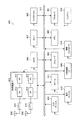
- FIG. 6 is a block diagram showing a configuration example of the terminal device 2 according to the embodiment of the present disclosure.
- the terminal device 2 includes an upper layer processing unit 201, a control unit 203, a reception unit 205, a transmission unit 207, and a transmission / reception antenna 209.
- the terminal device 2 can support one or more RATs (Radio Access Technology).
- the terminal device 2 may support both LTE and NR.
- a part or all of each part included in the terminal device 2 may be individually configured according to the RAT.
- the receiving unit 205 and the transmitting unit 207 are individually configured by LTE and NR.
- a part or all of each part included in the terminal device 2 shown in FIG. 6 may be individually configured according to a parameter set relating to a transmission signal.
- the radio receiver 2057 and radio transmitter 2077 may be individually configured depending on the set of parameters for the transmit signal.
- the upper layer processing unit 201 outputs uplink data (transport block) to the control unit 203.
- the upper layer processing unit 201 includes a medium access control (MAC) layer, a packet data integration protocol (PDCP) layer, a radio link control (RLC) layer, and a radio resource control (Radio). Resource Control: RRC) Performs layer processing. Further, the upper layer processing unit 201 generates control information for controlling the receiving unit 205 and the transmitting unit 207, and outputs the control information to the control unit 203.
- MAC medium access control
- PDCP packet data integration protocol
- RLC radio link control
- Radio Radio Resource Control
- the upper layer processing unit 201 performs processing and management related to RAT control, radio resource control, subframe setting, scheduling control, and / or CSI report control.
- the processing and management in the upper layer processing unit 201 are performed based on the predetermined settings and / or the settings based on the control information set or notified from the base station apparatus 1.
- the control information from the base station apparatus 1 includes RRC parameters, MAC control elements or DCI.
- the processing and management in the upper layer processing unit 201 may be performed individually according to the RAT.
- the upper layer processing unit 201 separately performs processing and management in LTE and processing and management in NR.
- management related to RAT is performed. For example, in RAT control, LTE management and / or NR management is performed.
- Management of NR includes setting and processing parameter sets for transmitted signals in NR cells.
- the setting information in the own device is managed.
- the generation and / or management of uplink data (transport block), system information, RRC message (RRC parameter), and / or MAC control element (CE: Control Element) is performed. Will be done.
- Subframe settings include uplink or downlink settings for subframes, subframe pattern settings, uplink downlink settings, uplink reference UL-DL settings, and / or downlink reference UL-DL settings.
- the subframe setting in the upper layer processing unit 201 is also referred to as a terminal subframe setting.
- control information for controlling scheduling for the receiving unit 205 and the transmitting unit 207 is generated based on the DCI (scheduling information) from the base station device 1.
- the control related to the CSI report to the base station apparatus 1 is performed.
- the channel measurement unit 2059 controls the settings related to the CSI reference resource to be assumed in order to calculate the CSI.
- CSI reporting control controls the resources (timing) used to report CSI based on DCI and / or RRC parameters.
- the control unit 203 controls the receiving unit 205 and the transmitting unit 207 based on the control information from the upper layer processing unit 201.
- the control unit 203 generates control information for the upper layer processing unit 201 and outputs it to the upper layer processing unit 201.
- the control unit 203 inputs the decoded signal from the decoding unit 2051 and the channel estimation result from the channel measurement unit 2059.
- the control unit 203 outputs the coded signal to the coding unit 2071. Further, the control unit 203 may be used to control the whole or a part of the terminal device 2.
- control unit 203 acquires information on the used signal waveform used for downlink communication with the base station device 1 from the base station device 1 via the receiving unit 205 among the single carrier signal and the multi-carrier signal.
- the information regarding the signal waveform used is information transmitted as a predetermined signal waveform (for example, a single carrier signal).
- the control unit 203 controls the reception unit 205 to perform downlink communication with the base station apparatus 1 using the signal waveform used.
- the receiving unit 205 receives the signal transmitted from the base station device 1 via the transmitting / receiving antenna 209 according to the control from the control unit 203, and further performs reception processing such as separation, demodulation, and decoding, and the reception processing is performed.
- the information is output to the control unit 203.
- the reception process in the receiving unit 205 is performed based on a predetermined setting or a notification or setting from the base station apparatus 1.
- the receiving unit 205 includes a decoding unit 2051, a demodulation unit 2053, a multiplex separation unit 2055, a radio receiving unit 2057, and a channel measuring unit 2059.
- the radio receiver 2057 converts the uplink signal received via the transmission / reception antenna 209 to an intermediate frequency (down-conversion), removes unnecessary frequency components, and maintains an appropriate signal level. Control of amplification level, orthogonal demodulation based on in-phase and orthogonal components of the received signal, conversion of analog and digital signals, removal of Guard Interval (GI), and / or Fast Fourier Transform. Extract the signal in the frequency domain by Transform: FFT).
- GI Guard Interval
- the wireless receiver 2057 can support a plurality of uplink signal waveforms.
- the details of the radio receiver 2057 in the terminal device 2 that supports both the first signal waveform (multicarrier signal) and the second signal waveform (single carrier signal) will be described with reference to FIGS. 7 to 9.
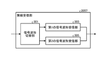
- FIG. 7 is a block diagram showing a configuration example of the wireless receiver 2057.
- the wireless reception unit 2057 includes a signal waveform switching unit 301, a first signal waveform reception unit 303, and a second signal waveform reception unit 305.
- the signal waveform switching unit 301 switches whether the received downlink communication is the first signal waveform or the second signal waveform according to a predetermined condition or situation.
- the received downlink communication is the first signal waveform
- the downlink communication is received and processed by the first signal waveform receiving unit 303.
- the received downlink communication is the second signal waveform
- the downlink communication is received and processed by the second signal waveform receiving unit 305.
- the switching conditions and situations in the signal waveform switching unit 301 will be described later.
- the signal waveform switching unit is also referred to as a signal waveform control unit. Further, in FIG. 7, the first signal waveform receiving unit 303 and the second signal waveform receiving unit 305 are described as different processing units, but only a part of the receiving processing is switched as one processing unit. It may be done.
- FIG. 8 is a block diagram showing a configuration example of the first signal waveform receiving unit 303.
- the first signal waveform receiving unit 303 performs reception processing on the downlink channel and the signal transmitted by CP-OFDM as the signal waveform of the downlink communication.
- the first signal waveform receiving unit 303 includes a CP removing unit 3031, an S / P unit 3033, a DFT (Discrete Fourier Transform) unit 3035, and a P / S unit 3037.
- the CP removal unit 3031 removes the CP (Cyclic prefix) added to the received downlink communication.
- the S / P unit 3033 converts the input serial signal into a parallel signal having a size of N.
- the DFT unit 3035 performs a Fourier transform process.
- the Fourier transform process can be FFT (Fast Fourier Transform) process.
- the P / S unit 3037 converts the input parallel signal of size M into a serial signal.
- a downlink communication signal transmitted by the terminal device 2 that performs reception processing is input to the P / S unit 3037.
- the size M is determined depending on the size of resources in the frequency domain used for downlink communication.
- FIG. 9 is a block diagram showing a configuration example of the second signal waveform receiving unit 305.
- the second signal waveform receiving unit 305 performs reception processing on the downlink channel and the signal transmitted by, for example, SC-FDMA as the signal waveform of the downlink communication.
- the second signal waveform receiving unit 305 includes a CP removing unit 3051, an S / P unit 3053, a DFT (Discrete Fourier Transform) unit 3055, and an IDFT (Inverse Discrete Fourier Transform) unit 3057.
- the CP removal unit 3051 removes the CP (Cyclic prefix) added to the received downlink communication.
- the S / P unit 3053 converts the input serial signal into a parallel signal having a size of N.
- the DFT unit 3055 performs a Fourier transform process.
- the Fourier transform process can be FFT (Fast Fourier Transform) process.
- the IDFT unit 3057 performs an inverse Fourier transform process on a signal having an input size of M.
- a downlink communication signal transmitted by the terminal device 2 that performs reception processing is input to the IDFT3057.
- the size M is determined depending on the size of resources in the frequency domain used for downlink communication.
- the multiplex separation unit 2055 separates the downlink channel such as PHICH, PDCCH, EPDCCH or PDSCH, the downlink synchronization signal and / or the downlink reference signal from the signal input from the radio reception unit 2057.
- the multiplex separation unit 2055 outputs a downlink reference signal to the channel measurement unit 2059.
- the multiple separation unit 2055 compensates the propagation path for the downlink channel from the estimated value of the propagation path input from the channel measurement unit 2059.
- the demodulation unit 2053 demodulates the received signal of the downlink channel modulation symbol using a modulation method such as BPSK, ⁇ / 2BPSK, QPSK, 16QAM, 64QAM, or 256QAM.
- the demodulation unit 2053 separates and demodulates the MIMO-multiplexed downlink channels.
- the decoding unit 2051 performs decoding processing on the coded bits of the demodulated downlink channel.
- the decoded downlink data and / or the downlink control information is output to the control unit 203.
- the decoding unit 2051 performs a decoding process for the PDSCH for each transport block.
- the channel measurement unit 2059 measures the estimated value of the propagation path and / or the quality of the channel from the downlink reference signal input from the multiplex separation unit 2055, and outputs the measurement to the multiplex separation unit 2055 and / or the control unit 203.
- the downlink reference signal used by the channel measurement unit 2059 for measurement may be determined based on at least the transmission mode set by the RRC parameter and / or other RRC parameters.
- DL-DMRS measures propagation path estimates for propagation path compensation for PDSCH or EPDCCH.
- the CRS measures propagation path estimates for propagation path compensation for PDCCH or PDSCH and / or channels on the downlink for reporting CSI.
- CSI-RS measures channels on the downlink for reporting CSI.
- the channel measurement unit 2059 calculates RSRP (Reference Signal Received Power) and / or RSRQ (Reference Signal Received Quality) based on the CRS, CSI-RS or the detection signal, and outputs the RSRP (Reference Signal Received Quality) to the upper layer processing unit 201.
- RSRP Reference Signal Received Power
- RSRQ Reference Signal Received Quality
- the transmission unit 207 performs transmission processing such as coding, modulation, and multiplexing on the uplink control information and uplink data input from the upper layer processing unit 201 according to the control from the control unit 203. For example, the transmission unit 207 generates and multiplexes an uplink channel such as PUSCH or PUCCH and / or an uplink reference signal to generate a transmission signal. The transmission process in the transmission unit 207 is performed based on a predetermined setting, or a setting or notification from the base station apparatus 1.
- the transmission unit 207 includes a coding unit 2071, a modulation unit 2073, a multiplexing unit 2075, a radio transmission unit 2077, and an uplink reference signal generation unit 2079.
- the coding unit 2071 converts the HARQ indicator (HARQ-ACK), uplink control information, and uplink data input from the control unit 203 into predetermined coding such as block coding, convolution coding, and turbo coding. Encoding is performed using the method.
- the modulation unit 2073 modulates the coding bits input from the coding unit 2071 by a predetermined modulation method such as BPSK, ⁇ / 2BPSK, QPSK, 16QAM, 64QAM, 256QAM.
- the uplink reference signal generation unit 2079 generates an uplink reference signal based on the RRC parameter or the like set in the terminal device 2.
- the multiplexing unit 2075 multiplexes the modulation symbols of each channel and the uplink reference signal and arranges them in a predetermined resource element.
- the radio transmission unit 2077 converts the signal from the multiplexing unit 2075 into a time region signal by an inverse fast Fourier transform (IFFT), adds a guard interval, and generates a baseband digital signal. Processes such as conversion to analog signal, orthogonal modulation, conversion from intermediate frequency signal to high frequency signal (up convert), removal of excess frequency components, power amplification, etc. are performed to generate a transmission signal. ..
- the transmission signal output by the wireless transmission unit 2077 is transmitted from the transmission / reception antenna 209.
- the base station device 1 and the terminal device 2 perform downlink communication using either a single carrier signal or a multi-carrier signal.
- the base station device 1 and the terminal device 2 each support one or more radio access technologies (RATs).
- RAT includes LTE and NR.
- One RAT corresponds to one cell (component carrier). That is, if multiple RATs are supported, each RAT corresponds to a different cell.
- the cell is a combination of downlink resources, uplink resources, and / or sidelinks.
- LTE Long Term Evolution
- NR New Radio Network
- the base station device 1 and the terminal device 2 can support communication using a set of one or more cells in the downlink, the uplink, and / or the side link.
- a collection of cells is also referred to as carrier aggregation or dual connectivity. Details of carrier aggregation and dual connectivity will be described later.
- each cell uses a predetermined frequency bandwidth. The maximum value, the minimum value, and the settable value in a predetermined frequency bandwidth can be specified in advance.
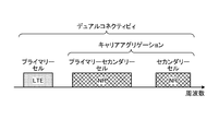
- FIG. 10 is a diagram showing an example of setting a component carrier in the embodiment of the present disclosure.
- one LTE cell and two NR cells are set.
- One LTE cell is set as the primary cell.
- the two NR cells are set as the primary secondary cell and the secondary cell, respectively.
- the two NR cells are integrated by carrier aggregation.
- LTE cells and NR cells will be integrated by dual connectivity.
- the LTE cell and the NR cell may be integrated by carrier aggregation.
- since the NR can be assisted by the LTE cell, which is the primary cell, it does not have to support some functions such as the function for communicating standalone.
- the functions for stand-alone communication include the functions required for the initial connection.
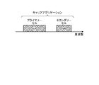
- FIG. 11 is a diagram showing an example of setting a component carrier in the embodiment of the present disclosure.
- two NR cells are set.
- the two NR cells are set as primary cells and secondary cells, respectively, and are integrated by carrier aggregation.
- the LTE cell assist is not required by supporting the function for the NR cell to communicate standalone.
- the two NR cells may be integrated by dual connectivity.
- FIG. 12 is an explanatory diagram showing an example of the frame configuration of NR.
- Each radio frame consisting of 10 ms is composed of two half frames.
- the time interval of the half frame is 5 ms.
- Each half frame consists of five subframes.
- one subframe is composed of one or more slots.
- One slot is composed of 14 symbols in the case of a normal CP and 12 symbols in the case of an extended CP.
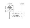
- FIG. 14 is a sequence diagram showing an example of the flow of communication processing according to the embodiment of the present disclosure.
- the base station apparatus 1 first determines whether or not to execute signal waveform switching (step S101). Subsequently, the base station apparatus 1 determines the signal waveform to be used when switching the signal waveform of the downlink communication (step S102). When the signal waveform switching is not executed, the base station apparatus 1 performs downlink communication using a signal waveform specified in advance.
- the base station device 1 notifies the terminal device 2 of the information (waveform information) regarding the determined signal used signal waveform (step S103). After that, the base station device 1 and the terminal device 2 perform downlink communication using the signal waveform used (step S104).
- downlink communication is performed by switching between a single carrier signal and a multicarrier signal.
- the base station apparatus 1 selects either a single carrier signal or a multicarrier signal.
- the base station apparatus 1 determines whether or not to execute the signal waveform switching process.
- the base station apparatus 1 determines whether or not to switch the signal waveform according to, for example, the capabilities of its own apparatus.
- the base station apparatus 1 determines whether or not to switch the signal waveform depending on, for example, the maximum transmission power of its own apparatus and the presence or absence of transmission circuits corresponding to a plurality of signal waveforms. For example, when the maximum transmission power of the base station device 1 is equal to or higher than a predetermined threshold value and the power amplifier can be operated in the linear region even if the multicarrier signal is transmitted, the base station device 1 does not switch the signal waveform.
- the base station device 1 has a transmission circuit corresponding to a single signal waveform, for example, when the base station device 1 has a transmission circuit corresponding to only a multi-carrier signal, the base station device 1 does not switch the signal waveform and the multi-carrier signal. Execute downlink communication with.
- the base station apparatus 1 may determine whether or not to switch the signal waveform according to the coverage and data throughput required for downlink communication. For example, when the required coverage is narrow, the transmission power can be small, so that the base station apparatus 1 selects a multicarrier signal having high frequency utilization efficiency and does not switch the signal waveform. Further, even when the required data throughput is high, the base station apparatus 1 selects a multicarrier signal having high frequency utilization efficiency and does not switch the signal waveform.
- the base station device 1 determines whether or not to switch the signal waveform according to the capability of the terminal device 2 which is the communication partner, for example. In this case, the base station device 1 determines whether or not to switch the signal waveform for each of the plurality of terminal devices 2. The base station device 1 determines whether or not to switch the signal waveform depending on whether or not the terminal device 2 has a receiving circuit corresponding to a plurality of signal waveforms, for example. For example, when the terminal device 2 has a receiving circuit corresponding to a single signal waveform, for example, when the terminal device 2 has a receiving circuit corresponding to only a multi-carrier signal, the base station device 1 does not switch the signal waveform and uses a multi-carrier signal. Executes downlink communication.
- the base station apparatus 1 determines that the switching process is to be executed, the base station apparatus 1 switches the signal waveform according to, for example, a physical channel or a frequency band.
- the base station device 1 switches signal waveforms for a predetermined physical channel or a predetermined frequency band.
- the target for which the base station apparatus 1 switches the signal waveform will be described.
- the base station apparatus 1 switches the signal waveform for, for example, a predetermined physical channel / signal.
- the base station apparatus 1 uses a signal waveform selected from a multi-carrier signal or a single-carrier signal for, for example, a physical channel / signal used for transmitting data information, more specifically, PDSCH or PDSCH DMRS.
- a physical channel / signal other than a predetermined physical channel for example, a physical channel / signal used for transmitting control information, more specifically, a predetermined signal waveform determined in advance for SSB, PDCCH, and CSI-RS.
- the base station apparatus 1 can widen the coverage and transmit control information more reliably by using a single carrier signal as a predetermined signal waveform.
- BWP bandwidth part
- the signal waveform is switched for a predetermined BWP.
- the base station apparatus 1 switches the signal waveform in other BWPs other than the initial active bandwidth, but transmits a signal in a predetermined signal waveform in the initial active bandwidth.
- the base station apparatus 1 uses, for example, the initial active bandwidth to notify information about other signal waveforms used in the BWP.
- the base station apparatus 1 switches the signal waveform for a predetermined cell. For example, the base station apparatus 1 switches signal waveforms in a secondary cell group (SCG) including a secondary cell and a secondary cell (Scell) for transmission.
- SCG secondary cell group
- Scell secondary cell
- the base station apparatus 1 transmits a signal with a predetermined signal waveform. In this case, the base station apparatus 1 uses, for example, Pcell or MCG to notify information about the signal waveform used in Scell or SCG.
- step S102 of FIG. 14 the selection criteria of the signal waveform used when the base station apparatus 1 selects the signal waveform used for the downlink communication will be described.
- the base station apparatus 1 switches the signal waveform according to the following selection criteria.
- the base station device 1 selects a signal waveform to be used according to the position of the terminal device 2. For example, when the base station device 1 and the terminal device 2 are separated from each other, a large transmission power is required. Since low PAPR is required to secure a large transmission power in the power amplifier, the base station apparatus 1 selects a single carrier signal as the signal waveform to be used when a large transmission power is required. On the other hand, when the distance between the base station device 1 and the terminal device is short, the transmission power may be small. Therefore, the PAPR may be high, and in this case, the base station apparatus 1 selects the multicarrier signal as the signal waveform to be used.
- FIG. 13 is a diagram showing the positional relationship between the base station device 1 and the terminal device 2.
- the base station apparatus 1 when the cell C is divided into two regions, the cell edge C1 and the cell center C2, the base station apparatus 1 is used as a signal waveform used for downlink communication with the terminal apparatus 2B at the cell edge C1. Select a single carrier signal. Further, the base station device 1 selects a multi-carrier signal as a signal waveform used for downlink communication with the terminal device 2A located at the cell center C2.
- the base station device 1 determines whether the terminal device 2 is at the cell edge C1 or at the cell center C2, for example, based on RSRP. More specifically, when the RSRP of the terminal device 2 is less than a predetermined threshold value, the base station device 1 determines that the distance from the terminal device 2 is long and the terminal device 2 is at the cell edge C1. On the other hand, when the RSRP of the terminal device 2 is equal to or higher than a predetermined threshold value, it is determined that the distance from the terminal device 2 is short and the terminal device 2 is located at the cell center C2.
- the base station device 1 may determine the position in the cell C based on the position information of the terminal device 2. For example, based on the position information acquired from GPS or the like mounted on the terminal device 2, the base station device 1 determines whether the terminal device 2 is at the cell edge C1 or at the cell center C2.
- the base station apparatus 1 may select a signal waveform according to the bandwidth or channel width used for downlink communication. For example, the wider the band, the lower the transmission power density. Therefore, in the case of a single carrier signal whose transmission power can be increased, the transmission power density can be ensured even if the band is widened. On the other hand, in the case of a multicarrier signal having a high PAPR and a difficulty in increasing the transmission power, the transmission power density decreases as the band becomes wider, so it is desirable to use the signal in a narrow band in order to secure the transmission power.
- the base station apparatus 1 selects a signal waveform according to the bandwidth or channel width used for downlink communication. Specifically, the base station apparatus 1 selects a single carrier signal when the bandwidth is equal to or more than a predetermined width, and selects a multicarrier signal when the bandwidth is less than the predetermined width.
- the base station apparatus 1 may select a signal waveform according to the time. For example, the base station apparatus 1 selects a single carrier signal at a predetermined time and selects a multicarrier signal at other times. In this way, the base station apparatus 1 can switch the signal waveform depending on the time.
- the base station device 1 switches the signal waveform for each slot, for example.
- the base station apparatus 1 selects a single carrier signal in a predetermined slot and a multicarrier signal in other slots.
- the time for selecting a single carrier signal may be the same as or different from the time for selecting a multicarrier signal (for example, the number of slots).
- the downlink communication time of the multi-carrier signal may be longer or shorter than that of the single-carrier signal.
- the multi-carrier signal and the single-carrier signal may be switched at the same cycle.
- the base station apparatus 1 selects the used signal waveform according to the used signal waveform in the uplink communication.
- uplink communication either a single carrier signal or a multicarrier signal is used.
- the base station apparatus 1 also uses the signal waveform used in the uplink communication in the downlink communication.
- the signal waveform to be used can be unified in the uplink communication and the downlink communication, and both the signal waveform used in the uplink communication and the downlink communication can be notified at one time. The details of the notification of information regarding the signal waveform used by the base station apparatus 1 will be described later.
- the base station apparatus 1 selects the used signal waveform according to the used signal waveform of another wireless communication system.
- the frequency band of 60 GHz is used not only for cellular communication but also for wireless communication according to the wireless LAN standard (for example, IEEE802.11ad, 11ay, etc.).
- the base station apparatus 1 selects a signal waveform used by the other wireless communication system as a signal waveform to be used.
- a single carrier signal is used in wireless communication according to IEEE802.11ad.
- the base station apparatus 1 that has detected the communication with the single carrier signal selects the single carrier signal as the signal waveform to be used.
- the other wireless communication system can more easily detect the signal transmitted by the base station apparatus 1. .. Similarly, the base station apparatus 1 can more easily detect signals transmitted and received by other wireless communication systems.
- the base station apparatus 1 switches the signal waveform at any of three frequencies of static, semi-static, and dynamic.
- the base station device 1 When statically switching the signal waveform, the base station device 1 once selects the signal waveform to be used and notifies the terminal device 2, and then uses the notified signal waveform.
- the base station apparatus 1 includes the information regarding the selected signal waveform used in the system information, for example, and notifies the terminal apparatus 2.
- the base station device 1 selects the signal waveform to be used at a predetermined cycle and notifies the terminal device 2.
- the base station apparatus 1 includes the information regarding the selected signal waveform used in the RRC signaling, for example, and notifies the terminal apparatus 2.
- the base station device 1 selects the signal waveform to be used each time the data information is transmitted and notifies the terminal device 2.
- the base station apparatus 1 includes the information regarding the selected signal waveform used in the PDCCH, for example, and notifies the terminal apparatus 2.
- the base station device 1 that has switched the used signal waveform notifies the terminal device 2 of the used signal waveform as shown in step S103 of FIG.
- a method of transmitting information about the signal waveform used by the base station device 1 to the terminal device 2 a method of transmitting it explicitly, a method of transmitting it implicitly, and a method of transmitting the signal waveform used by the terminal device 2 side.
- Three methods of blind detection can be considered.
- the base station apparatus 1 explicitly transmits information regarding the signal waveform used (hereinafter, also referred to as waveform information) will be described.
- the base station apparatus 1 includes the waveform information in, for example, system information, RRC signaling, or DCI and transmits the waveform information.
- System information System information is classified into MIB (Master Information Block) and SIB (System Information Block).
- the base station device 1 transmits the system information including the waveform information to the MIB, for example.
- Waveform information is added to the MIB, for example, as a 1-bit parameter.
- For the waveform information for example, by setting 1 or 0 for a 1-bit parameter, either a single carrier signal or a multi-carrier signal can be specified as the signal waveform.
- the waveform information is included in, for example, the SSB (Synchronization signal / PBCH block) of the MIB and transmitted.
- the base station apparatus 1 transmits the SSB with a predetermined signal waveform (for example, a single carrier signal), and transmits a physical downlink channel / signal other than the SSB with a signal waveform specified by the waveform information.
- the base station apparatus 1 transmits PDCCH and PDSCH included in the SIB as a signal waveform specified by waveform information.
- the base station apparatus 1 may transmit the system information including the waveform information to the SIB, for example.
- the base station apparatus 1 transmits the PDSCH scheduled by SSB, type0-PDCCH, and type0-PDCCH with a predetermined signal waveform (for example, a single carrier signal), and waveforms other physical downlink channels / signals.
- the signal waveform specified in the information is transmitted.
- the base station apparatus 1 transmits, for example, RRC signaling after RRC connection including a parameter indicating waveform information. As a result, the base station apparatus 1 can periodically notify the waveform information.
- the base station apparatus 1 transmits the waveform information including the waveform information to the DCC of the PDCCH.
- the base station apparatus 1 notifies the waveform information by the field included in DCI. As a result, the base station apparatus 1 can dynamically switch the signal waveform.
- the base station apparatus 1 when the base station apparatus 1 selects the same signal waveform as the uplink communication as the used signal waveform for the downlink communication, the base station apparatus 1 correlates with the notification regarding the used signal waveform for the uplink communication. Information may be notified.
- the base station device 1 notifies the notification regarding the signal waveform used for uplink communication as the signal waveform used for downlink communication.
- the base station apparatus 1 collectively notifies the information regarding the signal waveforms used in the uplink communication and the downlink communication as one piece of information.
- the waveform information is transmitted as a single carrier signal, for example, which complicates the multiplexing of resources between the single carrier signal and the multicarrier signal. Therefore, it is desirable to transmit the waveform information notification at the earliest possible stage, for example, system information such as MIB. However, if waveform information is notified by system information, it becomes difficult to assign a dynamic signal waveform.
- the base station apparatus 1 when the base station apparatus 1 first transmits the system information such as the MIB including the waveform information, and then switches the signal waveform to be used, it transmits the waveform information after switching to RRC signaling or DCI. You may do so.
- the base station apparatus 1 implicitly notifies the waveform information.
- the base station apparatus 1 notifies the terminal apparatus 2 of the waveform information by changing, for example, the SSB configuration, the PDCCH configuration, and the like according to the signal waveform used.
- the base station apparatus 1 For example, the correspondence between the signal waveform and the SSB configuration is predetermined, and the base station apparatus 1 notifies the terminal apparatus 2 of the waveform information by transmitting the SSB having the configuration corresponding to the selected signal waveform to be used. ..
- a PSS (Primary Synchronization Signal) and / or SSS (Secondary Synchronization Signal) sequence is defined for each signal waveform, and the base station apparatus 1 has a PSS and / or SSS according to the defined sequence.
- the terminal device 2 detects PSS and / or SSS, it determines that the signal waveform corresponding to the detected PSS and / or SSS is the signal waveform used.
- the base station apparatus 1 can notify the waveform information.
- the base station device 1 may notify the waveform information by allocating resources of PSS / SSS / PBCH (SSB block).
- PSS / SSS / PBCH (SSB block) resources are defined for each signal waveform.
- the terminal device 2 detects PSS / SSS / PBCH (SSB block)
- it determines that the signal waveform corresponding to the resource to which the detected PSS / SSS / PBCH (SSB block) is transmitted is the signal waveform used.
- the base station apparatus 1 can notify the waveform information by associating the signal waveform with the resource.
- the base station apparatus 1 For example, by associating the signal waveform with the CORESET of the PDCCH, the search space, the type of DCI, the RNTI, etc., the base station apparatus 1 notifies the terminal apparatus 2 of the waveform information by transmitting the PDCCH. You will be able to.
- the signal waveform is associated with each of CORESET, for example CORESET # 0 and other CORESET, and the base station apparatus 1 transmits either CORESET # 0 or other CORESET, so that the terminal apparatus 2 can perform. , Detects the signal waveform used.
- the signal waveform is associated with each of the CSS (Common Search Space) and USS (UE-specific Search Space) of the search space, and the base station device 1 is used depending on which search section the PDCCH is transmitted. Notify the terminal device 2 of the signal waveform.
- the signal waveform may be associated with each of the DCI types, for example, fallback DCI and non-fallback DCI.
- the base station device 1 transmits either the fallback DCI or the non-fallback DCI, so that the terminal device 2 detects the signal waveform used.
- the signal waveform may be associated with each of the RNTIs, such as C-RNTI and other RNTIs.
- the base station apparatus 1 transmits either C-RNTI or other RNTI, so that the terminal apparatus 2 detects the signal waveform used.
- the terminal device 2 acquires the waveform information by detecting the signal transmitted by the base station device 1 as the used signal waveform. There is a way to do it (blind detection).
- the single carrier signal has a low PAPR
- the multicarrier signal has a high PAPR. Therefore, for example, the terminal device 2 detects the amplitude fluctuation of the received signal to determine whether the signal waveform of the received signal is a single carrier signal or a multicarrier signal.
- the terminal device 2 blindly detects the state of the signal waveform of the downlink communication symbol. More specifically, the terminal device 2 detects an amplitude fluctuation (for example, PAPR) on the frequency axis, and if the detected fluctuation is less than a predetermined threshold value, determines that the signal waveform used is a single carrier signal. If it is equal to or higher than a predetermined threshold value, it is determined that the signal is a multicarrier signal.
- PAPR amplitude fluctuation
- the terminal device 2 can detect the used signal waveform even if the base station device 1 does not notify the waveform information.
- the base station apparatus 1 may change the frame configuration with the single carrier signal and the multicarrier signal so that the terminal apparatus 2 blindly detects the signal waveform.
- the base station device 1 changes the frame format, symbol length, CP configuration, etc. of the wireless frame for each signal waveform.
- the base station apparatus 1 changes the CP configuration between a single carrier signal and a multicarrier signal. More specifically, the base station apparatus 1 changes the configuration of the CP to, for example, zero padding or a unique word, depending on the signal waveform. If the CP configuration is zero padding, the power at the location corresponding to the CP of the wireless frame becomes zero. On the other hand, if the CP configuration is a unique word, the power of the part corresponding to the CP of the wireless frame does not become zero. Therefore, the terminal device 2 detects the signal waveform of the received signal by determining the power of the portion corresponding to the CP of the received signal as a threshold value.
- the base station device 1 can also include waveform information in the transmission signal and transmit the used signal waveform to the terminal device 2.
- the base station apparatus 1 includes the waveform information in the CP and transmits the waveform information.
- the base station device 1 and the terminal device 2 can perform communication using the used signal waveform even if the base station device 1 does not separately transmit the waveform information.
- the base station device 1 may change the symbol length according to, for example, the signal waveform used.
- one slot is composed of 14 symbols, but for example, the number of symbols in one slot may be changed according to the signal waveform. More specifically, in the base station device 1, for example, when communicating with a multi-carrier signal, the number of symbols in one slot is 14, and when communicating with a single carrier signal, the number of symbols in one slot is set as the multi-carrier signal. The number of symbols is 28, which is double the case of.
- the base station device 1 may change the number of CP symbols instead of the slots according to the signal waveform.
- the base station apparatus 1 continuously transmits a plurality of CPs in the case of a single carrier signal, and transmits one CP in the case of a multicarrier signal, for example.
- the base station apparatus 1 may change the number of CPs, that is, the CP length according to the signal waveform.
- the base station apparatus 1 changes the resource allocation method according to the signal waveform used. For example, the base station apparatus 1 allocates transmission signals to resources discontinuously when communicating with multicarrier signals. Further, in the case of a single carrier signal, the base station apparatus 1 continuously allocates the transmission signal to the resource.
- the base station apparatus 1 selects a single carrier signal when it wants to transmit the signal with low PAPR.
- Single carrier signals can be transmitted at low PAPR by combining them on the frequency. Therefore, when the single carrier signal is selected, the base station apparatus 1 selects discontinuous allocation (Resource allocation Type 1) as the resource allocation method.
- the base station device 1 selects discontinuous allocation (Resource allocation Type 0). As a result, the base station apparatus 1 can transmit a signal by utilizing a good characteristic on the frequency axis, and can improve the frequency utilization efficiency.
- the base station apparatus 1 determines the number of layers (multiplexed number) according to the signal waveform. For example, in the case of a single carrier signal, the number of layers is limited to two or less, vertically polarized wave and horizontally polarized wave. On the other hand, in the case of a multi-carrier signal, since the number of layers is not particularly limited, the base station apparatus 1 may transmit the multi-carrier signal, for example, by setting the number of layers to 3 or more.
- the base station apparatus 1 has 2 or less layers of MIMO, and in the case of a multi-carrier signal, the number of layers is 3 or more. In this way, the base station apparatus 1 determines the number of MIMO layers according to the signal waveform.
- the precoding and feedback from the terminal device 2 also differ depending on the signal waveform.
- CSI Channel State Information
- RI Rank Indicator
- PMI Precoding Matrix Indicator
- the base station apparatus 1 determines the modulation method according to the signal waveform. For example, the base station apparatus 1 performs downlink communication using a single carrier signal when low PAPR is required. Therefore, when the base station apparatus 1 uses a single carrier signal, the base station apparatus 1 selects a modulation method having a low PAPR. Examples of the modulation method having low PAPR include ⁇ / 2BPSK.
- the base station apparatus 1 performs downlink communication using a multi-carrier signal when there is no problem even if the PAPR is high. Therefore, when the base station apparatus 1 uses the multi-carrier signal, the base station apparatus 1 selects a modulation method other than the modulation method having a low PAPR. For example, the base station apparatus 1 selects a modulation method such as QPSK or 16QAM, which has better transmission efficiency than BPSK, as the modulation method of the multicarrier signal.
- a modulation method such as QPSK or 16QAM, which has better transmission efficiency than BPSK
- the base station apparatus 1 can improve the transmission efficiency while satisfying the demand for low PAPR by determining the modulation method according to the signal waveform.
- the base station apparatus 1 determines the signal waveform used for downlink communication from among a plurality of signal waveforms including the single carrier signal.
- the base station device 1 notifies the terminal device 2 of information (waveform information) regarding the determined signal used signal waveform.
- the terminal device 2 that has acquired the notification performs downlink communication with the base station device 1 using the signal waveform used.
- the base station apparatus 1 selects a single carrier signal to satisfy the low PAPR requirement, and the base station apparatus 1 selects a signal waveform other than the single carrier signal to further improve the transmission efficiency of the entire system. Can be made to.
- the base station apparatus 1 may be realized as any kind of eNB (evolved Node B) such as a macro eNB or a small eNB.
- the small eNB may be an eNB that covers cells smaller than the macro cell, such as a pico eNB, a micro eNB, or a home (femto) eNB.
- the base station apparatus 1 may be realized as another type of base station such as NodeB or BTS (Base Transceiver Station).
- the base station device 1 may include a main body (also referred to as a base station device) that controls wireless communication, and one or more RRHs (Remote Radio Heads) arranged at a location different from the main body. Further, various types of terminals, which will be described later, may operate as the base station device 1 by temporarily or semi-permanently executing the base station function.
- a main body also referred to as a base station device
- RRHs Remote Radio Heads
- the terminal device 2 is a smartphone, a tablet PC (Personal Computer), a notebook PC, a portable game terminal, a mobile terminal such as a portable / dongle type mobile router or a digital camera, or an in-vehicle terminal such as a car navigation device. It may be realized as. Further, the terminal device 2 may be realized as a terminal (also referred to as an MTC (Machine Type Communication) terminal) that performs M2M (Machine To Machine) communication. Further, the terminal device 2 may be a wireless communication module (for example, an integrated circuit module composed of one die) mounted on these terminals.
- MTC Machine Type Communication
- FIG. 15 is a block diagram showing a first example of a schematic configuration of an eNB to which the techniques according to the present disclosure can be applied.
- the eNB 800 has one or more antennas 810 and a base station device 820. Each antenna 810 and base station device 820 may be connected to each other via an RF cable.
- Each of the antennas 810 has a single antenna element or a plurality of antenna elements (for example, a plurality of antenna elements constituting a MIMO antenna), and is used for transmitting and receiving a radio signal by the base station apparatus 820.
- the eNB 800 has a plurality of antennas 810 as shown in FIG. 15, and the plurality of antennas 810 may correspond to a plurality of frequency bands used by the eNB 800, for example.
- FIG. 15 shows an example in which the eNB 800 has a plurality of antennas 810, the eNB 800 may have a single antenna 810.
- the base station device 820 includes a controller 821, a memory 822, a network interface 823, and a wireless communication interface 825.
- the controller 821 may be, for example, a CPU or a DSP, and operates various functions of the upper layer of the base station apparatus 820. For example, the controller 821 generates a data packet from the data in the signal processed by the wireless communication interface 825, and transfers the generated packet via the network interface 823. The controller 821 may generate a bundled packet by bundling data from a plurality of baseband processors and transfer the generated bundled packet. In addition, the controller 821 is a logic that executes control such as radio resource management (Radio Resource Control), radio bearer control (Radio Bearer Control), mobility management (Mobility Management), inflow control (Admission Control), or scheduling (Scheduling). Function.
- Radio Resource Control Radio Resource Control
- Radio Bearer Control Radio Bearer Control
- Mobility Management Mobility Management
- Admission Control Inflow control
- scheduling scheduling
- the control may be executed in cooperation with the peripheral eNB or the core network node.
- the memory 822 includes RAM and ROM, and stores a program executed by the controller 821 and various control data (for example, terminal list, transmission power data, scheduling data, and the like).
- the network interface 823 is a communication interface for connecting the base station device 820 to the core network 824. Controller 821 may communicate with a core network node or other eNB via network interface 823. In that case, the eNB 800 and the core network node or other eNB may be connected to each other by a logical interface (for example, S1 interface or X2 interface).
- the network interface 823 may be a wired communication interface or a wireless communication interface for a wireless backhaul. When the network interface 823 is a wireless communication interface, the network interface 823 may use a frequency band higher than the frequency band used by the wireless communication interface 825 for wireless communication.
- the wireless communication interface 825 supports either a cellular communication method such as LTE (Long Term Evolution) or LTE-Advanced, and provides a wireless connection to a terminal located in the cell of the eNB 800 via the antenna 810.
- the wireless communication interface 825 may typically include a baseband (BB) processor 826, an RF circuit 827, and the like.
- the BB processor 826 may perform, for example, coding / decoding, modulation / demodulation, and multiplexing / demultiplexing, and each layer (for example, L1, MAC (Medium Access Control), RLC (Radio Link Control), and PDCP. (Packet Data Convergence Protocol)) Performs various signal processing.
- L1, MAC Medium Access Control
- RLC Radio Link Control
- PDCP Packet Data Convergence Protocol
- the BB processor 826 may have some or all of the above-mentioned logical functions instead of the controller 821.
- the BB processor 826 may be a module including a memory for storing a communication control program, a processor for executing the program, and related circuits, and the function of the BB processor 826 may be changed by updating the above program. Good.
- the module may be a card or a blade inserted into the slot of the base station device 820, or may be a chip mounted on the card or the blade.
- the RF circuit 827 may include a mixer, a filter, an amplifier, and the like, and transmits and receives radio signals via the antenna 810.
- the wireless communication interface 825 includes a plurality of BB processors 826 as shown in FIG. 15, and the plurality of BB processors 826 may correspond to a plurality of frequency bands used by, for example, the eNB 800. Further, the wireless communication interface 825 includes a plurality of RF circuits 827 as shown in FIG. 15, and the plurality of RF circuits 827 may correspond to, for example, a plurality of antenna elements. Although FIG. 15 shows an example in which the wireless communication interface 825 includes a plurality of BB processors 826 and a plurality of RF circuits 827, the wireless communication interface 825 includes a single BB processor 826 or a single RF circuit 827. It may be.
- FIG. 16 is a block diagram showing a second example of a schematic configuration of an eNB to which the techniques according to the present disclosure can be applied.
- the eNB 830 has one or more antennas 840, a base station device 850, and an RRH 860.
- Each antenna 840 and RRH860 may be connected to each other via an RF cable.
- the base station apparatus 850 and RRH860 may be connected to each other by a high-speed line such as an optical fiber cable.
- Each of the antennas 840 has a single antenna element or a plurality of antenna elements (for example, a plurality of antenna elements constituting a MIMO antenna) and is used for transmitting and receiving a radio signal by the RRH860.
- the eNB 830 has a plurality of antennas 840 as shown in FIG. 16, and the plurality of antennas 840 may correspond to a plurality of frequency bands used by the eNB 830, for example.
- FIG. 16 shows an example in which the eNB 830 has a plurality of antennas 840, the eNB 830 may have a single antenna 840.
- the base station device 850 includes a controller 851, a memory 852, a network interface 853, a wireless communication interface 855, and a connection interface 857.
- the controller 851, memory 852, and network interface 853 are similar to the controller 821, memory 822, and network interface 823 described with reference to FIG.
- the wireless communication interface 855 supports either a cellular communication method such as LTE or LTE-Advanced, and provides a wireless connection to a terminal located in a sector corresponding to the RRH860 via the RRH860 and the antenna 840.
- the wireless communication interface 855 may typically include a BB processor 856 and the like.
- the BB processor 856 is similar to the BB processor 826 described with reference to FIG. 15, except that it is connected to the RF circuit 864 of the RRH860 via the connection interface 857.
- the wireless communication interface 855 includes a plurality of BB processors 856 as shown in FIG. 16, and the plurality of BB processors 856 may correspond to a plurality of frequency bands used by, for example, the eNB 830.
- FIG. 16 shows an example in which the wireless communication interface 855 includes a plurality of BB processors 856, the wireless communication interface 855 may include a single BB processor 856.
- connection interface 857 is an interface for connecting the base station device 850 (wireless communication interface 855) to the RRH860.
- the connection interface 857 may be a communication module for communication on the high-speed line connecting the base station device 850 (wireless communication interface 855) and the RRH 860.
- the RRH860 also includes a connection interface 861 and a wireless communication interface 863.
- connection interface 861 is an interface for connecting the RRH860 (wireless communication interface 863) to the base station device 850.
- the connection interface 861 may be a communication module for communication on the high-speed line.
- the wireless communication interface 863 transmits and receives wireless signals via the antenna 840.
- the wireless communication interface 863 may typically include RF circuits 864 and the like.
- the RF circuit 864 may include a mixer, a filter, an amplifier, and the like, and transmits and receives radio signals via the antenna 840.
- the wireless communication interface 863 includes a plurality of RF circuits 864, and the plurality of RF circuits 864 may correspond to, for example, a plurality of antenna elements.
- FIG. 16 shows an example in which the wireless communication interface 863 includes a plurality of RF circuits 864, the wireless communication interface 863 may include a single RF circuit 864.
- the eNB 800, eNB 830, base station device 820 or base station device 850 shown in FIGS. 15 and 16 can correspond to the base station device 1 described with reference to FIG. 2 and the like.
- FIG. 17 is a block diagram showing an example of a schematic configuration of a smartphone 900 to which the technology according to the present disclosure can be applied.
- the smartphone 900 includes a processor 901, a memory 902, a storage 903, an external connection interface 904, a camera 906, a sensor 907, a microphone 908, an input device 909, a display device 910, a speaker 911, a wireless communication interface 912, and one or more antenna switches 915. It comprises one or more antennas 916, bus 917, battery 918 and auxiliary controller 919.
- the processor 901 may be, for example, a CPU or a SoC (System on Chip), and controls the functions of the application layer and other layers of the smartphone 900.
- Memory 902 includes RAM and ROM and stores programs and data executed by processor 901.
- the storage 903 may include a storage medium such as a semiconductor memory or a hard disk.
- the external connection interface 904 is an interface for connecting an external device such as a memory card or a USB (Universal Serial Bus) device to the smartphone 900.
- the camera 906 has an image sensor such as a CCD (Charge Coupled Device) or a CMOS (Complementary Metal Oxide Semiconductor) and generates an captured image.
- the sensor 907 may include, for example, a group of sensors such as a positioning sensor, a gyro sensor, a geomagnetic sensor and an acceleration sensor.
- the microphone 908 converts the voice input to the smartphone 900 into a voice signal.
- the input device 909 includes, for example, a touch sensor, a keypad, a keyboard, a button, or a switch for detecting a touch on the screen of the display device 910, and receives an operation or information input from the user.
- the display device 910 has a screen such as a liquid crystal display (LCD) or an organic light emitting diode (OLED) display, and displays an output image of the smartphone 900.
- the speaker 911 converts the voice signal output from the smartphone 900 into voice.
- the wireless communication interface 912 supports either LTE or LTE-Advanced cellular communication method and executes wireless communication.
- the wireless communication interface 912 may typically include a BB processor 913, an RF circuit 914, and the like.
- the BB processor 913 may perform, for example, coding / decoding, modulation / demodulation, multiplexing / demultiplexing, and the like, and performs various signal processing for wireless communication.
- the RF circuit 914 may include a mixer, a filter, an amplifier, and the like, and transmits and receives radio signals via the antenna 916.
- the wireless communication interface 912 may be a one-chip module in which a BB processor 913 and an RF circuit 914 are integrated.
- the wireless communication interface 912 may include a plurality of BB processors 913 and a plurality of RF circuits 914 as shown in FIG. Although FIG. 17 shows an example in which the wireless communication interface 912 includes a plurality of BB processors 913 and a plurality of RF circuits 914, the wireless communication interface 912 includes a single BB processor 913 or a single RF circuit 914. It may be.
- the wireless communication interface 912 may support other types of wireless communication systems such as a short-range wireless communication system, a near field wireless communication system, or a wireless LAN (Local Area Network) system in addition to the cellular communication system.
- a short-range wireless communication system such as a Bluetooth Special Interest Group (SIG) system
- a near field wireless communication system such as a Wi-Fi Protected Access
- a wireless LAN Local Area Network
- the BB processor 913 and the RF circuit 914 for each wireless communication system may be included.
- Each of the antenna switches 915 switches the connection destination of the antenna 916 between a plurality of circuits (for example, circuits for different wireless communication methods) included in the wireless communication interface 912.
- Each of the antennas 916 has a single antenna element or a plurality of antenna elements (for example, a plurality of antenna elements constituting a MIMO antenna) and is used for transmitting and receiving a radio signal by the wireless communication interface 912.
- the smartphone 900 may have a plurality of antennas 916 as shown in FIG. Although FIG. 17 shows an example in which the smartphone 900 has a plurality of antennas 916, the smartphone 900 may have a single antenna 916.
- the smartphone 900 may be provided with an antenna 916 for each wireless communication method.
- the antenna switch 915 may be omitted from the configuration of the smartphone 900.
- the bus 917 connects the processor 901, the memory 902, the storage 903, the external connection interface 904, the camera 906, the sensor 907, the microphone 908, the input device 909, the display device 910, the speaker 911, the wireless communication interface 912, and the auxiliary controller 919 to each other. ..
- the battery 918 supplies electric power to each block of the smartphone 900 shown in FIG. 17 via a power supply line partially shown by a broken line in the figure.
- the auxiliary controller 919 operates the minimum necessary functions of the smartphone 900, for example, in the sleep mode.
- FIG. 18 is a block diagram showing an example of a schematic configuration of a car navigation device 920 to which the technique according to the present disclosure can be applied.
- the car navigation device 920 includes a processor 921, a memory 922, a GPS (Global Positioning System) module 924, a sensor 925, a data interface 926, a content player 927, a storage medium interface 928, an input device 929, a display device 930, a speaker 931, and wireless communication. It comprises an interface 933, one or more antenna switches 936, one or more antennas 937, and a battery 938.
- GPS Global Positioning System
- the processor 921 may be, for example, a CPU or an SoC, and controls the navigation function and other functions of the car navigation device 920.
- Memory 922 includes RAM and ROM and stores programs and data executed by processor 921.
- the GPS module 924 measures the position (eg, latitude, longitude and altitude) of the car navigation device 920 using GPS signals received from GPS satellites.
- the sensor 925 may include, for example, a group of sensors such as a gyro sensor, a geomagnetic sensor and a barometric pressure sensor.
- the data interface 926 is connected to the vehicle-mounted network 941 via a terminal (not shown), and acquires data generated on the vehicle side such as vehicle speed data.
- the content player 927 plays the content stored in the storage medium (for example, CD or DVD) inserted in the storage medium interface 928.
- the input device 929 includes, for example, a touch sensor, a button, or a switch that detects a touch on the screen of the display device 930, and accepts an operation or information input from the user.
- the display device 930 has a screen such as an LCD or an OLED display, and displays an image of a navigation function or a content to be reproduced.
- the speaker 931 outputs the sound of the navigation function or the content to be played.
- the wireless communication interface 933 supports either LTE or LTE-Advanced cellular communication method and executes wireless communication.
- the wireless communication interface 933 may typically include a BB processor 934, an RF circuit 935, and the like.
- the BB processor 934 may perform, for example, coding / decoding, modulation / demodulation and multiplexing / demultiplexing, and performs various signal processing for wireless communication.
- the RF circuit 935 may include a mixer, a filter, an amplifier, and the like, and transmits and receives radio signals via the antenna 937.
- the wireless communication interface 933 may be a one-chip module in which a BB processor 934 and an RF circuit 935 are integrated.
- the wireless communication interface 933 may include a plurality of BB processors 934 and a plurality of RF circuits 935 as shown in FIG. Although FIG. 18 shows an example in which the wireless communication interface 933 includes a plurality of BB processors 934 and a plurality of RF circuits 935, the wireless communication interface 933 includes a single BB processor 934 or a single RF circuit 935. It may be.
- the wireless communication interface 933 may support other types of wireless communication systems such as a short-range wireless communication system, a proximity wireless communication system, or a wireless LAN system in addition to the cellular communication system.
- a BB processor 934 and an RF circuit 935 for each communication method may be included.
- Each of the antenna switches 936 switches the connection destination of the antenna 937 between a plurality of circuits (for example, circuits for different wireless communication methods) included in the wireless communication interface 933.
- Each of the antennas 937 has a single antenna element or a plurality of antenna elements (for example, a plurality of antenna elements constituting a MIMO antenna) and is used for transmitting and receiving a radio signal by the wireless communication interface 933.
- the car navigation device 920 may have a plurality of antennas 937 as shown in FIG. Although FIG. 18 shows an example in which the car navigation device 920 has a plurality of antennas 937, the car navigation device 920 may have a single antenna 937.
- the car navigation device 920 may be provided with an antenna 937 for each wireless communication method.
- the antenna switch 936 may be omitted from the configuration of the car navigation device 920.
- the battery 938 supplies electric power to each block of the car navigation device 920 shown in FIG. 18 via a power supply line partially shown by a broken line in the figure. In addition, the battery 938 stores electric power supplied from the vehicle side.
- the technique according to the present disclosure may be realized as an in-vehicle system (or vehicle) 940 including one or more blocks of the car navigation device 920 described above, an in-vehicle network 941, and a vehicle-side module 942.
- the vehicle-side module 942 generates vehicle-side data such as vehicle speed, engine speed, or failure information, and outputs the generated data to the vehicle-mounted network 941.
- the case of switching the signal waveform of the downlink communication is mainly described in the cellular communication, but the signal waveform of the downlink communication may be switched in the communication other than the cellular communication.
- a signal is transmitted from a wireless communication device mounted on a satellite (hereinafter, also referred to as a satellite station) to a terrestrial wireless communication device (hereinafter, also referred to as a ground station), the satellite station switches the signal waveform. May be good.
- each component of each device shown in the figure is a functional concept, and does not necessarily have to be physically configured as shown in the figure. That is, the specific form of distribution / integration of each device is not limited to the one shown in the figure, and all or part of the device is functionally or physically dispersed / physically distributed in arbitrary units according to various loads and usage conditions. Can be integrated and configured.
- the information is acquired from the base station apparatus, and the information is obtained from the base station apparatus.
- a control unit that performs downlink communication with the base station device using the signal waveform used.
- a terminal device comprising.
- the control unit Regardless of the signal waveform used, at least one of the synchronization signal block, PDCCH (Physical Downlink Control Channel), or PDSCH (Physical Downlink Shared Channel) scheduled by PDCCH is received with a predetermined signal waveform.
- the terminal device according to (2) (4) The terminal device according to (1), wherein the information regarding the signal waveform used is transmitted using RRC signaling. (5) The terminal device according to (1), wherein the information regarding the signal waveform used is included in the DCI field in PDCCH. (6) The terminal device according to (1), wherein the signal waveform used is a signal waveform used for uplink communication with the base station device. (7)
- the plurality of signal waveforms correspond to a plurality of sequences of synchronous signals, respectively.
- the control unit The signal waveform used is determined according to the sequence of the received synchronization signals.
- the terminal device according to (1). (8)
- the control unit The usage signal waveform is used for communication with the secondary cell group based on the information regarding the usage signal waveform acquired through communication with the master cell group.
- the terminal device according to (1). (9) Determine the signal waveform to be used for downlink communication with the terminal device from multiple signal waveforms including the single carrier signal. Information on the signal waveform used is notified using a predetermined signal waveform among the plurality of signal waveforms.
- the control unit The signal waveform used is determined according to whether the terminal device is at the center of the cell or at the edge of the cell.
- the plurality of signal waveforms further include a multi-carrier signal.
- the predetermined signal waveform is a single carrier signal.
- (12) The control unit Allocate the multicarrier signal discontinuously to the resource
- the single carrier signal is continuously assigned to the resource.
- the control unit When multiplexing data signals to be transmitted to a plurality of the terminal devices to the same resource, the number of multiplexings is determined according to the signal waveform used.
- the control unit The modulation method of the signal to be transmitted to the terminal device is determined according to the signal waveform used.
- the base station apparatus according to (9).
- the information is acquired from the base station apparatus, and the information is obtained from the base station apparatus. Based on the information, the downlink communication is performed with the base station device using the signal waveform used.
- Communication method (16) Determine the signal waveform to be used for downlink communication with the terminal device from multiple signal waveforms including the single carrier signal. Information on the signal waveform used is notified using a predetermined signal waveform among the plurality of signal waveforms.
- the downlink communication is performed with the terminal device using the notified signal waveform. Communication method.
- Base station equipment 101 Upper layer processing unit 103 Control unit 105 Reception unit 1051 Decoding unit 1053 Decompression unit 1055 Multiple separation unit 1057 Wireless reception unit 1059 Channel measurement unit 107 Transmission unit 1071 Coding unit 1073 Modulation unit 1075 Multiplex unit 1077 Wireless transmission Part 1079 Downlink reference signal generation part 109 Transmission / reception antenna 2 Terminal device 201 Upper layer processing part 203 Control part 205 Reception part 2051 Decoding part 2053 Demodition part 2055 Multiplexing part 2057 Wireless reception part 2059 Channel measurement part 207 Transmission part 2071 Coding Part 2073 Modulation part 2075 Multiplexing part 2077 Wireless transmission part 2079 Uplink reference signal generation part 209 Transmission / reception antenna
Landscapes
- Engineering & Computer Science (AREA)
- Signal Processing (AREA)
- Computer Networks & Wireless Communication (AREA)
- Physics & Mathematics (AREA)
- Discrete Mathematics (AREA)
- General Physics & Mathematics (AREA)
- Mathematical Physics (AREA)
- Mobile Radio Communication Systems (AREA)
Abstract
Description
1.はじめに
2.実施形態
2.1.通信システムの概要
2.2.通信システムの構成例
2.2.1.基地局装置の構成例
2.2.2.端末装置の構成例
2.3.通信システムの処理
2.3.1.通信処理の流れ
2.3.2.基地局装置による信号波形の切り替え処理
2.3.3.使用信号波形の通知処理
2.3.4.使用信号波形に応じた通信処理
3.応用例
3.1.基地局に関する応用例
3.2.端末装置に関する応用例
4.その他の実施形態
5.補足
近年の多様な無線システムが混在する無線環境および無線を介したコンテンツ量の増加と多様化に伴い、無線システムに割り当て可能な電波資源(周波数)の枯渇が問題として表面化してきている。このような状況から、利用可能な電波資源を捻出するために、より周波数帯域が確保しやすいミリ波、特に52.6GHzから110GHzの周波数帯域のミリ波を用いた運用が検討されている。
・High data RATe eMBB
・Mobile data offloading
・Short-range high data RATe D2D communications
・Vertical industry factory application
・Broadband distribution network
・IntegRATed access backhaul (IAB)
・Factory automation/Industrial IoT (IIoT)
・Augmented reality/virtual reality headsets and other high-end wearables
・Intelligent Transport System (ITS) and V2X
・Data center inter-rack connectivity
・Smart grid automation
・Radar/positioning
・マルチパスに対しての分離が容易
・周波数ごとのデジタルプリコーディングが容易
・周波数軸上における、リソースのNon-contiguous allocationが容易
<2.1.通信システムの概要>
そこで、本開示の技術では、低PAPRおよびシステム全体の効率の向上を実現するために、シングルキャリア信号を含む複数の信号波形のうちの1つを使用して下りリンク通信を行う。本開示の技術の概要について図1を用いて説明する。
次に、本開示の実施形態に係る通信システムの構成例について説明する。上述したように、本実施形態に係る通信システムは、基地局装置1と端末装置2とを備える。
図2は、本開示の実施形態に係る基地局装置1の構成例を示すブロック図である。図2に示すように、基地局装置1は、上位層処理部101、制御部103、受信部105、送信部107、および、送受信アンテナ109、を含んで構成される。
上位層処理部101は、下りリンクデータ(トランスポートブロック)を、制御部103に出力する。上位層処理部101は、媒体アクセス制御(MAC: Medium Access Control)層、パケットデータ統合プロトコル(Packet Data Convergence Protocol: PDCP)層、無線リンク制御(Radio Link Control: RLC)層、無線リソース制御(Radio Resource Control: RRC)層の処理を行う。また、上位層処理部101は、受信部105、および送信部107の制御を行うために制御情報を生成し、制御部103に出力する。
制御部103は、上位層処理部101からの制御情報に基づいて、受信部105および送信部107の制御を行う。制御部103は、上位層処理部101への制御情報を生成し、上位層処理部101に出力する。制御部103は、復号化部1051からの復号化された信号およびチャネル測定部1059からのチャネル推定結果を入力する。制御部103は、符号化する信号を符号化部1071へ出力する。また、制御部103は、基地局装置1の全体または一部を制御するために用いられる。
受信部105は、制御部103からの制御にしたがって、送受信アンテナ109を介して端末装置2から送信された信号を受信し、さらに分離、復調、復号などの受信処理を行い、受信処理された情報を制御部103に出力する。なお、受信部105における受信処理は、あらかじめ規定された設定、または基地局装置1が端末装置2に通知した設定に基づいて行われる。受信部105は、復号化部1051、復調部1053、多重分離部1055、無線受信部1057、およびチャネル測定部1059を含んで構成される。
無線受信部1057は、送受信アンテナ109を介して受信された上りリンクの信号に対して、中間周波数への変換(ダウンコンバート)、不要な周波数成分の除去、信号レベルが適切に維持されるように増幅レベルの制御、受信された信号の同相成分および直交成分に基づく直交復調、アナログ信号からディジタル信号への変換、ガードインターバル(Guard Interval: GI)の除去、および/または、高速フーリエ変換(Fast Fourier Transform: FFT)による周波数領域信号の抽出を行う。
多重分離部1055は、無線受信部1057から入力された信号から、PUCCHまたはPUSCHなどの上りリンクチャネルおよび/または上りリンク参照信号を分離する。多重分離部1055は、上りリンク参照信号をチャネル測定部1059に出力する。多重分離部1055は、チャネル測定部1059から入力された伝搬路の推定値から、上りリンクチャネルに対する伝搬路の補償を行う。
復調部1053は、上りリンクチャネルの変調シンボルに対して、BPSK(Binary Phase Shift Keying)、π/2BPSK、QPSK(Quadrature Phase shift Keying)、16QAM(Quadrature Amplitude Modulation)、64QAM、256QAM等の変調方式を用いて受信信号の復調を行う。復調部1053は、MIMO多重された上りリンクチャネルの分離および復調を行う。
復号化部1051は、復調された上りリンクチャネルの符号化ビットに対して、復号処理を行う。復号された上りリンクデータおよび/または上りリンク制御情報は制御部103へ出力される。復号化部1051は、PUSCHに対しては、トランスポートブロック毎に復号処理を行う。
チャネル測定部1059は、多重分離部1055から入力された上りリンク参照信号から伝搬路の推定値および/またはチャネルの品質などを測定し、多重分離部1055および/または制御部103に出力する。例えば、チャネル測定部1059は、UL-DMRSを用いてPUCCHまたはPUSCHに対する伝搬路補償を行うための伝搬路の推定値を測定し、SRSを用いて上りリンクにおけるチャネルの品質を測定する。
送信部107は、制御部103からの制御にしたがって、上位層処理部101から入力された下りリンク制御情報および下りリンクデータに対して、符号化、変調および多重などの送信処理を行う。例えば、送信部107は、PHICH、PDCCH、EPDCCH、PDSCH、および下りリンク参照信号を生成および多重し、送信信号を生成する。なお、送信部107における送信処理は、あらかじめ規定された設定、基地局装置1が端末装置2に通知した設定、または、同一のサブフレームで送信されるPDCCHまたはEPDCCHを通じて通知される設定に基づいて行われる。送信部107は、符号化部1071、変調部1073、多重部1075、無線送信部1077、および下りリンク参照信号生成部1079を含んで構成される。
符号化部1071は、制御部103から入力されたHARQインディケータ(HARQ-ACK)、下りリンク制御情報、および、下りリンクデータを、ブロック符号化、畳込み符号化、ターボ符号化等の所定の符号化方式を用いて符号化を行う。変調部1073は、符号化部1071から入力された符号化ビットをBPSK、π/2BPSK、QPSK、16QAM、64QAM、256QAM等の所定の変調方式で変調する。下りリンク参照信号生成部1079は、物理セル識別子(PCI:Physical cell identification)、端末装置2に設定されたRRCパラメータなどに基づいて、下りリンク参照信号を生成する。
多重部1075は、各チャネルの変調シンボルと下りリンク参照信号を多重し、所定のリソースエレメントに配置する。
無線送信部1077は、多重部1075からの信号に対して、逆高速フーリエ変換(Inverse Fast Fourier Transform: IFFT)による時間領域の信号への変換、ガードインターバルの付加、ベースバンドのディジタル信号の生成、アナログ信号への変換、直交変調、中間周波数の信号から高周波数の信号への変換(アップコンバート: up convert)、余分な周波数成分の除去、電力の増幅などの処理を行い、送信信号を生成する。無線送信部1077が出力した送信信号は、送受信アンテナ109から送信される。
図6は、本開示の実施形態に係る端末装置2の構成例を示すブロック図である。図6に示すように、端末装置2は、上位層処理部201、制御部203、受信部205、送信部207、および、送受信アンテナ209を含んで構成される。
上位層処理部201は、上りリンクデータ(トランスポートブロック)を、制御部203に出力する。上位層処理部201は、媒体アクセス制御(MAC: Medium Access Control)層、パケットデータ統合プロトコル(Packet Data Convergence Protocol: PDCP)層、無線リンク制御(Radio Link Control: RLC)層、無線リソース制御(Radio Resource Control: RRC)層の処理を行なう。また、上位層処理部201は、受信部205、および送信部207の制御を行うために制御情報を生成し、制御部203に出力する。
制御部203は、上位層処理部201からの制御情報に基づいて、受信部205および送信部207の制御を行う。制御部203は、上位層処理部201への制御情報を生成し、上位層処理部201に出力する。制御部203は、復号化部2051からの復号化された信号およびチャネル測定部2059からのチャネル推定結果を入力する。制御部203は、符号化する信号を符号化部2071へ出力する。また、制御部203は、端末装置2の全体または一部を制御するために用いられてもよい。
受信部205は、制御部203からの制御にしたがって、送受信アンテナ209を介して基地局装置1から送信された信号を受信し、さらに分離、復調、復号などの受信処理を行い、受信処理された情報を制御部203に出力する。なお、受信部205における受信処理は、あらかじめ規定された設定、または基地局装置1からの通知または設定に基づいて行われる。受信部205は、復号化部2051、復調部2053、多重分離部2055、無線受信部2057、およびチャネル測定部2059を含んで構成される。
無線受信部2057は、送受信アンテナ209を介して受信された上りリンクの信号に対して、中間周波数への変換(ダウンコンバート)、不要な周波数成分の除去、信号レベルが適切に維持されるように増幅レベルの制御、受信された信号の同相成分および直交成分に基づく直交復調、アナログ信号からディジタル信号への変換、ガードインターバル(Guard Interval: GI)の除去、および/または、高速フーリエ変換(Fast Fourier Transform: FFT)による周波数領域の信号の抽出を行う。
図6に戻る多重分離部2055は、無線受信部2057から入力された信号から、PHICH、PDCCH、EPDCCHまたはPDSCHなどの下りリンクチャネル、下りリンク同期信号および/または下りリンク参照信号を分離する。多重分離部2055は、下りリンク参照信号をチャネル測定部2059に出力する。多重分離部2055は、チャネル測定部2059から入力された伝搬路の推定値から、下りリンクチャネルに対する伝搬路の補償を行う。
復調部2053は、下りリンクチャネルの変調シンボルに対して、BPSK、π/2BPSK、QPSK、16QAM、64QAM、256QAM等の変調方式を用いて受信信号の復調を行う。復調部2053は、MIMO多重された下りリンクチャネルの分離および復調を行う。
復号化部2051は、復調された下りリンクチャネルの符号化ビットに対して、復号処理を行う。復号された下りリンクデータおよび/または下りリンク制御情報は制御部203へ出力される。復号化部2051は、PDSCHに対しては、トランスポートブロック毎に復号処理を行う。
チャネル測定部2059は、多重分離部2055から入力された下りリンク参照信号から伝搬路の推定値および/またはチャネルの品質などを測定し、多重分離部2055および/または制御部203に出力する。チャネル測定部2059が測定に用いる下りリンク参照信号は、少なくともRRCパラメータによって設定される送信モードおよび/または他のRRCパラメータに基づいて決定されてもよい。例えば、DL-DMRSはPDSCHまたはEPDCCHに対する伝搬路補償を行うための伝搬路の推定値を測定する。CRSはPDCCHまたはPDSCHに対する伝搬路補償を行うための伝搬路の推定値、および/または、CSIを報告するための下りリンクにおけるチャネルを測定する。CSI-RSは、CSIを報告するための下りリンクにおけるチャネルを測定する。チャネル測定部2059は、CRS、CSI-RSまたは検出信号に基づいて、RSRP(Reference Signal Received Power)および/またはRSRQ(Reference Signal Received Quality)を算出し、上位層処理部201へ出力する。
送信部207は、制御部203からの制御にしたがって、上位層処理部201から入力された上りリンク制御情報および上りリンクデータに対して、符号化、変調および多重などの送信処理を行う。例えば、送信部207は、PUSCHまたはPUCCHなどの上りリンクチャネルおよび/または上りリンク参照信号を生成および多重し、送信信号を生成する。なお、送信部207における送信処理は、あらかじめ規定された設定、または、基地局装置1から設定または通知に基づいて行われる。送信部207は、符号化部2071、変調部2073、多重部2075、無線送信部2077、および上りリンク参照信号生成部2079を含んで構成される。
符号化部2071は、制御部203から入力されたHARQインディケータ(HARQ-ACK)、上りリンク制御情報、および上りリンクデータを、ブロック符号化、畳込み符号化、ターボ符号化等の所定の符号化方式を用いて符号化を行う。変調部2073は、符号化部2071から入力された符号化ビットをBPSK、π/2BPSK、QPSK、16QAM、64QAM、256QAM等の所定の変調方式で変調する。上りリンク参照信号生成部2079は、端末装置2に設定されたRRCパラメータなどに基づいて、上りリンク参照信号を生成する。
多重部2075は、各チャネルの変調シンボルと上りリンク参照信号を多重し、所定のリソースエレメントに配置する。
無線送信部2077は、多重部2075からの信号に対して、逆高速フーリエ変換(Inverse Fast Fourier Transform: IFFT)による時間領域の信号への変換、ガードインターバルの付加、ベースバンドのディジタル信号の生成、アナログ信号への変換、直交変調、中間周波数の信号から高周波数の信号への変換(アップコンバート: up convert)、余分な周波数成分の除去、電力の増幅などの処理を行い、送信信号を生成する。無線送信部2077が出力した送信信号は、送受信アンテナ209から送信される。
続いて、本開示の実施形態に係る通信システムの通信処理について説明する。上述したように、本実施形態に係る通信システムは、シングルキャリア信号またはマルチキャリア信号のいずれか一方を用いて、基地局装置1と端末装置2とが下りリンク通信を行う。
上述したように、本実施形態において、基地局装置1および端末装置2は、それぞれ1つ以上の無線アクセス技術(RAT)をサポートする。例えば、RATは、LTEおよびNRを含む。1つのRATは、1つのセル(コンポーネントキャリア)に対応する。すなわち、複数のRATがサポートされる場合、それらのRATは、それぞれ異なるセルに対応する。本実施形態において、セルは、下りリンクリソース、上りリンクリソース、および/または、サイドリンクの組み合わせである。また、以下の説明において、LTEに対応するセルはLTEセルと呼称され、NRに対応するセルはNRセルと呼称される。
次に、無線フレームの構成例として、NRのフレーム構成例について説明する。図12は、NRのフレーム構成の一例を示す説明図である。10msで構成される無線フレーム(radio frame)のそれぞれは2つのハーフフレームから構成される。ハーフフレームの時間間隔は、5msである。ハーフフレームのそれぞれは、5つのサブフレームから構成される。さらに、1つのサブフレームは、1つ以上のスロットで構成される。1つのスロットは、ノーマルCPの場合14個、拡張CPの場合12個のシンボルで構成される。
続いて、図14を用いて、本開示の実施形態に係る通信システムにおける通信処理の流れを説明する。図14は、本開示の実施形態に係る通信処理の流れの一例を示すシーケンス図である。
上述したように、本実施形態に係る通信システムでは、シングルキャリア信号およびマルチキャリア信号を切り替えて下りリンク通信を行う。下りリンク通信において、基地局装置1がシングルキャリア信号またはマルチキャリア信号のいずれかを選択する。
まず、基地局装置1は、図14のステップS101に示したように、信号波形の切り替え処理を実行するか否かを判定する。基地局装置1は、例えば自装置のケイパビリティに応じて信号波形を切り替えるか否かを判定する。基地局装置1は、例えば自装置の最大送信電力や、複数の信号波形に対応する送信回路の有無に応じて信号波形を切り替えるか否かを判定する。例えば、基地局装置1の最大送信電力が所定閾値以上であり、マルチキャリア信号を送信してもパワーアンプを線形領域で動作させることができる場合、基地局装置1は、信号波形を切り替えず、マルチキャリア信号で下りリンク通信を実行する。あるいは、基地局装置1が単一の信号波形に対応する送信回路を有する場合、例えばマルチキャリア信号のみに対応する送信回路を有する場合、基地局装置1は、信号波形を切り替えず、マルチキャリア信号で下りリンク通信を実行する。
基地局装置1は、切り替え処理を実行すると判定した場合に、例えば物理チャネルや周波数帯域に応じて信号波形を切り替える。基地局装置1は、所定の物理チャネルや所定の周波数帯域を対象として信号波形を切り替える。以下、基地局装置1が信号波形を切り替える対象について説明する。
基地局装置1は、例えば所定の物理チャネル/信号を対象に信号波形を切り替える。基地局装置1は、例えばデータ情報の伝送に使われる物理チャネル/信号、より具体的には、PDSCHやPDSCH DMRSには、マルチキャリア信号またはシングルキャリア信号のうち選択した信号波形を用いる。一方、所定の物理チャネル以外の物理チャネル/信号、例えば制御情報の伝送に使われる物理チャネル/信号、より具体的には、SSB、PDCCH、CSI-RSには、予め決められた所定の信号波形が使用される。例えば基地局装置1は、所定の信号波形としてシングルキャリア信号を使用することで、カバレッジを広くすることができ、制御情報をより確実に送信することができる。
例えば、帯域幅パート(Bandwidth part:BWP)と称される連続する共通リソースブロックのサブセットが設定される場合、所定のBWPを対象に信号波形を切り替える。例えば、基地局装置1は、initial active bandwidthを除く他のBWPでは、信号波形を切り替えるが、initial active bandwidthでは所定の信号波形で信号を送信する。この場合、基地局装置1は、例えばinitial active bandwidthを用いて、その他のBWPで使用する信号波形に関する情報を通知する。
上述したように、通信システムがキャリアアグリゲーションまたはデュアルコネクティビティを用いる通信をサポートする場合、基地局装置1は、所定のセルを対象に信号波形を切り替える。例えば、基地局装置1は、セカンダリーセルやセカンダリーセル(Scell)を含むセカンダリーセルグループ(SCG)では信号波形を切り替えて送信を行う。一方、プライマリーセル(Pcell)や、プライマリーセルを含むマスタセルグループ(MCG)では、基地局装置1は所定の信号波形で信号を送信する。この場合、基地局装置1は、例えばPcellあるいはMCGを用いて、ScellあるいはSCGで使用する信号波形に関する情報を通知する。
続いて、図14のステップS102で、基地局装置1が下りリンク通信に使用する信号波形を選択する場合の、使用信号波形の選択基準について説明する。基地局装置1は、以下の選択基準に応じて信号波形を切り替える。
・帯域幅あるいはチャネル幅
・時間
・上りリンク通信での使用信号波形
・他の無線通信システムの使用信号波形
基地局装置1は、端末装置2の位置に応じて、使用信号波形を選択する。例えば、基地局装置1と端末装置2との距離が離れている場合、大きな送信電力が必要となる。パワーアンプで大きな送信電力を確保するためには低PAPRが求められるため、基地局装置1は、大きな送信電力が必要な場合、使用信号波形としてシングルキャリア信号を選択する。一方、基地局装置1と端末装置との距離が近い場合、送信電力は小さくてもよい。そのため、PAPRが高くてもよく、この場合、基地局装置1は、使用信号波形としてマルチキャリア信号を選択する。
あるいは、基地局装置1が、下りリンク通信に使用する帯域幅またはチャネル幅に応じて信号波形を選択してもよい。例えば、帯域が広くなるほど、送信電力密度が小さくなる。そのため、送信電力を大きくできるシングルキャリア信号の場合、帯域を広くしても送信電力密度を確保することができる。一方、PAPRが高く、送信電力が大きくしづらいマルチキャリア信号の場合、帯域が広くなると送信電力密度が小さくなるため、送信電力を確保するために狭い帯域で使用することが望ましい。
あるいは、基地局装置1が時間に応じて信号波形を選択してもよい。例えば、基地局装置1は、所定の時間ではシングルキャリア信号を選択し、それ以外の時間ではマルチキャリア信号を選択する。このように、基地局装置1は、時間によって信号波形を切り替えることができる。
基地局装置1は、上りリンク通信での使用信号波形に応じて、使用信号波形を選択する。上りリンク通信では、シングルキャリア信号またはマルチキャリア信号のいずれかが使用される。この場合、基地局装置1は、上りリンク通信で使用する信号波形を、下りリンク通信でも使用する。これにより、例えば、使用する信号波形を上りリンク通信および下りリンク通信で統一することができ、1度で上りリンク通信および下りリンク通信の使用信号波形の両方を通知することができるようになる。なお、基地局装置1による使用信号波形に関する情報の通知について、詳細は後述する。
基地局装置1は、他の無線通信システムの使用信号波形に応じて、使用信号波形を選択する。例えば、60GHzの周波数帯域は、セルラー通信以外にも例えば無線LAN規格に従った無線通信(例えばIEEE802.11ad、11ay等)でも使用される。基地局装置1は、同じ周波数帯域で通信を行う他の無線通信システムが検出された場合、他の無線通信システムが使用する信号波形を、使用信号波形として選択する。例えば、IEEE802.11adに従った無線通信ではシングルキャリア信号が使用される。かかるシングルキャリア信号での通信を検出した基地局装置1は、シングルキャリア信号を使用信号波形として選択する。
基地局装置1は、スタティック、セミスタティック、および、ダイナミックの3つの頻度のいずれかで信号波形を切り替える。
使用信号波形を切り替えた基地局装置1は、図14のステップS103に示すように、使用信号波形を端末装置2に通知する。基地局装置1が使用信号波形に関する情報を端末装置2に送信する方法として、Explicit(明示的)に送信する方法と、Implicit(暗黙的)に送信する方法と、端末装置2側が使用信号波形をブラインド検出する方法の3つの方法が考えられる。
まず、基地局装置1が明示的に使用信号波形に関する情報(以下、波形情報ともいう)を送信する場合について説明する。この場合、基地局装置1は、波形情報を、例えばシステム情報、RRCシグナリングまたはDCIに含めて送信する。
システム情報は、MIB(Master Information Block)と、SIB(System Information Block)とに分類される。
基地局装置1は、例えばRRC接続後のRRCシグナリングに波形情報を示すパラメータを含めて送信する。これにより基地局装置1は、周期的に波形情報を通知することができる。
基地局装置1は、PDCCHのDCIに波形情報を含めて送信する。基地局装置1は、DCIに含まれるfieldによって波形情報を通知する。これにより、基地局装置1は、ダイナミックに信号波形を切り替えることができる。
上述したように、基地局装置1が上りリンク通信と同じ信号波形を下りリンク通信の使用信号波形として選択した場合、基地局装置1は、上りリンク通信の使用信号波形に関する通知に対応付けて波形情報を通知するようにしてもよい。
次に、基地局装置1が暗黙的に波形情報を通知する場合について説明する。この場合、基地局装置1は、使用信号波形に応じて、例えばSSBの構成、PDCCHの構成等を変更することで、端末装置2に波形情報を通知する。
例えば、信号波形とSSBの構成との対応関係が予め決められており、基地局装置1は選択した使用信号波形に対応する構成のSSBを送信することで、端末装置2に波形情報を通知する。
例えば、信号波形をPDCCHのCORESETや探索空間(search space)、DCIの種類、RNTI等に対応付けておくことにより、基地局装置1が、PDCCHを送信することで波形情報を端末装置2に通知することができるようになる。
上述したように、基地局装置1が明示的あるいは暗黙的に波形情報を送る以外にも、基地局装置1が使用信号波形で送信した信号を、端末装置2が検出することで波形情報を取得する方法(ブラインド検出)がある。
上述したようにシングルキャリア信号は低PAPRであるのに対し、マルチキャリア信号は高PAPRである。そこで、例えば端末装置2が受信信号の振幅変動を検出することで、受信信号の信号波形がシングルキャリア信号またはマルチキャリア信号のどちらかを判定する。
PAPRによる検出以外にも、例えば基地局装置1がシングルキャリア信号およびマルチキャリア信号でフレーム構成を変更することで、端末装置2が信号波形をブラインド検出するようにしてもよい。
基地局装置1は、上述した方法で使用信号波形に関する情報を通知すると、図14のステップS104に示すように、使用信号波形を用いて端末装置2と下りリンク通信を行う。ここでは、使用信号波形に応じて基地局装置1が実行する通信処理について説明する。
基地局装置1は、使用信号波形に応じてリソースの割り当て方法を変更する。例えば、基地局装置1は、マルチキャリア信号で通信を行う場合、送信信号を非連続的にリソースに割り当てる。また、シングルキャリア信号の場合、基地局装置1は、送信信号を連続的にリソースに割り当てる。
基地局装置1は、例えばMIMOのように、データ信号を同一リソースに多重化して送信する場合、信号波形に応じてlayer数(多重化数)を決定する。例えば、シングルキャリア信号の場合、layer数は、垂直偏波、水平偏波の2つ以下に制限される。一方、マルチキャリア信号の場合、layer数に特に制限がないため、基地局装置1は、例えばlayer数を3以上にしてマルチキャリア信号を送信してもよい。
また、基地局装置1は、信号波形に応じて変調方式を決定する。例えば、基地局装置1は、低PAPRが求められる場合に、シングルキャリア信号を用いて下りリンク通信を行う。そこで、基地局装置1は、シングルキャリア信号を使用する場合、低PAPRである変調方式を選択する。低PAPRである変調方式としては、例えばπ/2BPSKが挙げられる。
本開示に係る技術は、様々な製品へ応用可能である。例えば、基地局装置1は、マクロeNB又はスモールeNBなどのいずれかの種類のeNB(evolved Node B)として実現されてもよい。スモールeNBは、ピコeNB、マイクロeNB又はホーム(フェムト)eNBなどの、マクロセルよりも小さいセルをカバーするeNBであってよい。その代わりに、基地局装置1は、NodeB又はBTS(Base Transceiver Station)などの他の種類の基地局として実現されてもよい。基地局装置1は、無線通信を制御する本体(基地局装置ともいう)と、本体とは別の場所に配置される1つ以上のRRH(Remote Radio Head)とを含んでもよい。また、後述する様々な種類の端末が一時的に又は半永続的に基地局機能を実行することにより、基地局装置1として動作してもよい。
(第1の応用例)
図15は、本開示に係る技術が適用され得るeNBの概略的な構成の第1の例を示すブロック図である。eNB800は、1つ以上のアンテナ810、および基地局装置820を有する。各アンテナ810および基地局装置820は、RFケーブルを介して互いに接続され得る。
図16は、本開示に係る技術が適用され得るeNBの概略的な構成の第2の例を示すブロック図である。eNB830は、1つ以上のアンテナ840、基地局装置850、およびRRH860を有する。各アンテナ840およびRRH860は、RFケーブルを介して互いに接続され得る。また、基地局装置850およびRRH860は、光ファイバケーブルなどの高速回線で互いに接続され得る。
(第1の応用例)
図17は、本開示に係る技術が適用され得るスマートフォン900の概略的な構成の一例を示すブロック図である。スマートフォン900は、プロセッサ901、メモリ902、ストレージ903、外部接続インタフェース904、カメラ906、センサ907、マイクロフォン908、入力デバイス909、表示デバイス910、スピーカ911、無線通信インタフェース912、1つ以上のアンテナスイッチ915、1つ以上のアンテナ916、バス917、バッテリー918および補助コントローラ919を備える。
図18は、本開示に係る技術が適用され得るカーナビゲーション装置920の概略的な構成の一例を示すブロック図である。カーナビゲーション装置920は、プロセッサ921、メモリ922、GPS(Global Positioning System)モジュール924、センサ925、データインタフェース926、コンテンツプレーヤ927、記憶媒体インタフェース928、入力デバイス929、表示デバイス930、スピーカ931、無線通信インタフェース933、1つ以上のアンテナスイッチ936、1つ以上のアンテナ937およびバッテリー938を備える。
上述した各実施形態に係る処理は、上記各実施形態以外にも種々の異なる形態にて実施されてよい。
以上、添付図面を参照しながら本開示の好適な実施形態について詳細に説明したが、本開示の技術的範囲はかかる例に限定されない。本開示の技術分野における通常の知識を有する者であれば、請求の範囲に記載された技術的思想の範疇内において、各種の変更例又は修正例に想到し得ることは明らかであり、これらについても、当然に本開示の技術的範囲に属するものと了解される。
(1)
シングルキャリア信号を含む複数の信号波形のうち、基地局装置との下りリンク通信に使用する使用信号波形に関する情報であって、前記複数の信号波形のうちの所定の信号波形を用いて送信される前記情報を、前記基地局装置から取得し、
前記情報に基づき、前記使用信号波形で前記基地局装置と前記下りリンク通信を行う制御部、
を備える端末装置。
(2)
前記使用信号波形に関する情報は、システム情報に含まれる、(1)に記載の端末装置。
(3)
前記制御部は、
前記使用信号波形にかかわらず、同期信号ブロック、PDCCH(Physical Downlink Control Channel)、または、PDCCHによりスケジュールされたPDSCH(Physical Downlink Shared Channel)の少なくとも1つを所定の信号波形で受信する、
(2)に記載の端末装置。
(4)
前記使用信号波形に関する情報は、RRCシグナリングを用いて送信される、(1)に記載の端末装置。
(5)
前記使用信号波形に関する情報は、PDCCHにおけるDCIのfieldに含まれる、(1)に記載の端末装置。
(6)
前記使用信号波形は、前記基地局装置との上りリンク通信に使用される信号波形である、(1)に記載の端末装置。
(7)
前記複数の信号波形は、複数の同期信号のシーケンスにそれぞれ対応し、
前記制御部は、
受信した前記同期信号のシーケンスに応じて前記使用信号波形を決定する、
(1)に記載の端末装置。
(8)
前記制御部は、
マスタセルグループとの通信を介して取得した前記使用信号波形に関する前記情報に基づき、セカンダリーセルグループとの通信に前記使用信号波形を使用する、
(1)に記載の端末装置。
(9)
シングルキャリア信号を含む複数の信号波形から端末装置との下りリンク通信に使用する使用信号波形を決定し、
前記複数の信号波形のうち所定の信号波形を用いて前記使用信号波形に関する情報を通知し、
通知した前記使用信号波形を用いて前記端末装置と前記下りリンク通信を行う制御部、
を備える基地局装置。
(10)
前記制御部は、
前記端末装置がセルのセル中心にいるかセルエッジにいるかに応じて前記使用信号波形を決定する、
(9)に記載の基地局装置。
(11)
前記複数の信号波形は、マルチキャリア信号をさらに含み、
前記所定の信号波形は、シングルキャリア信号である、
(9)に記載の基地局装置。
(12)
前記制御部は、
前記マルチキャリア信号を非連続的にリソースに割り当て、
前記シングルキャリア信号を連続的にリソースに割り当てる、
(11)に記載の基地局装置。
(13)
前記制御部は、
複数の前記端末装置に送信するデータ信号を同一リソースに多重化する場合、前記使用信号波形に応じて多重化数を決定する、
(9)に記載の基地局装置。
(14)
前記制御部は、
前記使用信号波形に応じて、前記端末装置に送信する信号の変調方式を決定する、
(9)に記載の基地局装置。
(15)
シングルキャリア信号を含む複数の信号波形のうち、基地局装置との下りリンク通信に使用する使用信号波形に関する情報であって、前記複数の信号波形のうちの所定の信号波形を用いて送信される前記情報を、前記基地局装置から取得し、
前記情報に基づき、前記使用信号波形で前記基地局装置と前記下りリンク通信を行う、
通信方法。
(16)
シングルキャリア信号を含む複数の信号波形から端末装置との下りリンク通信に使用する使用信号波形を決定し、
前記複数の信号波形のうち所定の信号波形を用いて前記使用信号波形に関する情報を通知し、
通知した前記使用信号波形を用いて前記端末装置と前記下りリンク通信を行う、
通信方法。
101 上位層処理部
103 制御部
105 受信部
1051 復号化部
1053 復調部
1055 多重分離部
1057 無線受信部
1059 チャネル測定部
107 送信部
1071 符号化部
1073 変調部
1075 多重部
1077 無線送信部
1079 下りリンク参照信号生成部
109 送受信アンテナ
2 端末装置
201 上位層処理部
203 制御部
205 受信部
2051 復号化部
2053 復調部
2055 多重分離部
2057 無線受信部
2059 チャネル測定部
207 送信部
2071 符号化部
2073 変調部
2075 多重部
2077 無線送信部
2079 上りリンク参照信号生成部
209 送受信アンテナ
Claims (16)
- シングルキャリア信号を含む複数の信号波形のうち、基地局装置との下りリンク通信に使用する使用信号波形に関する情報であって、前記複数の信号波形のうちの所定の信号波形を用いて送信される前記情報を、前記基地局装置から取得し、
前記情報に基づき、前記使用信号波形で前記基地局装置と前記下りリンク通信を行う制御部、
を備える端末装置。 - 前記使用信号波形に関する情報は、システム情報に含まれる、請求項1に記載の端末装置。
- 前記制御部は、
前記使用信号波形にかかわらず、同期信号ブロック、PDCCH(Physical Downlink Control Channel)、または、PDCCHによりスケジュールされたPDSCH(Physical Downlink Shared Channel)の少なくとも1つを所定の信号波形で受信する、
請求項2に記載の端末装置。 - 前記使用信号波形に関する情報は、RRCシグナリングを用いて送信される、請求項1に記載の端末装置。
- 前記使用信号波形に関する情報は、PDCCHにおけるDCIのfieldに含まれる、請求項1に記載の端末装置。
- 前記使用信号波形は、前記基地局装置との上りリンク通信に使用される信号波形である、請求項1に記載の端末装置。
- 前記複数の信号波形は、複数の同期信号のシーケンスにそれぞれ対応し、
前記制御部は、
受信した前記同期信号のシーケンスに応じて前記使用信号波形を決定する、
請求項1に記載の端末装置。 - 前記制御部は、
マスタセルグループとの通信を介して取得した前記使用信号波形に関する前記情報に基づき、セカンダリーセルグループとの通信に前記使用信号波形を使用する、
請求項1に記載の端末装置。 - シングルキャリア信号を含む複数の信号波形から端末装置との下りリンク通信に使用する使用信号波形を決定し、
前記複数の信号波形のうち所定の信号波形を用いて前記使用信号波形に関する情報を通知し、
通知した前記使用信号波形を用いて前記端末装置と前記下りリンク通信を行う制御部、
を備える基地局装置。 - 前記制御部は、
前記端末装置がセルのセル中心にいるかセルエッジにいるかに応じて前記使用信号波形を決定する、
請求項9に記載の基地局装置。 - 前記複数の信号波形は、マルチキャリア信号をさらに含み、
前記所定の信号波形は、シングルキャリア信号である、
請求項9に記載の基地局装置。 - 前記制御部は、
前記マルチキャリア信号を非連続的にリソースに割り当て、
前記シングルキャリア信号を連続的にリソースに割り当てる、
請求項11に記載の基地局装置。 - 前記制御部は、
複数の前記端末装置に送信するデータ信号を同一リソースに多重化する場合、前記使用信号波形に応じて多重化数を決定する、
請求項9に記載の基地局装置。 - 前記制御部は、
前記使用信号波形に応じて、前記端末装置に送信する信号の変調方式を決定する、
請求項9に記載の基地局装置。 - シングルキャリア信号を含む複数の信号波形のうち、基地局装置との下りリンク通信に使用する使用信号波形に関する情報であって、前記複数の信号波形のうちの所定の信号波形を用いて送信される前記情報を、前記基地局装置から取得し、
前記情報に基づき、前記使用信号波形で前記基地局装置と前記下りリンク通信を行う、
通信方法。 - シングルキャリア信号を含む複数の信号波形から端末装置との下りリンク通信に使用する使用信号波形を決定し、
前記複数の信号波形のうち所定の信号波形を用いて前記使用信号波形に関する情報を通知し、
通知した前記使用信号波形を用いて前記端末装置と前記下りリンク通信を行う、
通信方法。
Priority Applications (4)
| Application Number | Priority Date | Filing Date | Title |
|---|---|---|---|
| CN202080081028.6A CN114731667B (zh) | 2019-11-29 | 2020-11-24 | 终端装置、基站设备和通信方法 |
| US17/770,057 US12641615B2 (en) | 2019-11-29 | 2020-11-24 | Terminal device, base station apparatus, and communication method |
| EP20893805.0A EP4068885A4 (en) | 2019-11-29 | 2020-11-24 | TERMINAL DEVICE, BASE STATION DEVICE AND COMMUNICATION METHOD |
| KR1020227015776A KR20220108042A (ko) | 2019-11-29 | 2020-11-24 | 단말 장치, 기지국 장치 및 통신 방법 |
Applications Claiming Priority (2)
| Application Number | Priority Date | Filing Date | Title |
|---|---|---|---|
| JP2019-217326 | 2019-11-29 | ||
| JP2019217326 | 2019-11-29 |
Publications (1)
| Publication Number | Publication Date |
|---|---|
| WO2021106837A1 true WO2021106837A1 (ja) | 2021-06-03 |
Family
ID=76130471
Family Applications (1)
| Application Number | Title | Priority Date | Filing Date |
|---|---|---|---|
| PCT/JP2020/043587 Ceased WO2021106837A1 (ja) | 2019-11-29 | 2020-11-24 | 端末装置、基地局装置および通信方法 |
Country Status (5)
| Country | Link |
|---|---|
| US (1) | US12641615B2 (ja) |
| EP (1) | EP4068885A4 (ja) |
| KR (1) | KR20220108042A (ja) |
| CN (1) | CN114731667B (ja) |
| WO (1) | WO2021106837A1 (ja) |
Cited By (7)
| Publication number | Priority date | Publication date | Assignee | Title |
|---|---|---|---|---|
| WO2022190379A1 (ja) * | 2021-03-12 | 2022-09-15 | 株式会社Nttドコモ | 端末及び通信方法 |
| WO2023095708A1 (ja) * | 2021-11-26 | 2023-06-01 | ソニーグループ株式会社 | 基地局装置、無線通信装置および無線通信システム |
| WO2023134585A1 (zh) * | 2022-01-12 | 2023-07-20 | 维沃移动通信有限公司 | 下行传输方法、终端及网络侧设备 |
| US20230328719A1 (en) * | 2022-04-12 | 2023-10-12 | Qualcomm Incorporated | Semi-persistent waveform switching for uplink |
| WO2025099840A1 (ja) * | 2023-11-07 | 2025-05-15 | 株式会社Nttドコモ | 端末、無線通信方法及び基地局 |
| US20250233693A1 (en) * | 2022-02-01 | 2025-07-17 | Sony Group Corporation | Wireless telecommunications apparatuses and methods |
| WO2025173433A1 (ja) * | 2024-02-16 | 2025-08-21 | ソニーグループ株式会社 | 基地局装置、無線通信装置、無線通信方法およびプログラム |
Families Citing this family (9)
| Publication number | Priority date | Publication date | Assignee | Title |
|---|---|---|---|---|
| CN116506951B (zh) * | 2022-01-18 | 2026-08-11 | 维沃移动通信有限公司 | Bwp上的波形确定方法及终端 |
| US20260181642A1 (en) * | 2022-01-20 | 2026-06-25 | Beijing Xiaomi Mobile Software Co., Ltd. | Method and apparatus for switching bwp, and communication device and storage medium |
| JP7647941B2 (ja) * | 2022-02-07 | 2025-03-18 | 日本電信電話株式会社 | 無線通信方法、無線通信システムおよび無線送信装置 |
| US11632271B1 (en) * | 2022-02-24 | 2023-04-18 | T-Mobile Usa, Inc. | Location-based channel estimation in wireless communication systems |
| US12689991B2 (en) * | 2022-11-06 | 2026-07-21 | Qualcomm Incorporated | Techniques for power headroom reporting for dynamic waveform switching |
| US12581321B2 (en) | 2023-04-11 | 2026-03-17 | Dish Wireless L.L.C. | Carrier aggregation and dual connectivity switching in a cellular network |
| WO2025086074A1 (zh) * | 2023-10-23 | 2025-05-01 | 北京小米移动软件有限公司 | 通信方法、终端、网络设备、通信系统及存储介质 |
| CN118101029A (zh) * | 2024-02-01 | 2024-05-28 | 上海星思半导体有限责任公司 | 波形模式的确定方法及装置 |
| KR20260103542A (ko) * | 2024-12-26 | 2026-07-03 | 삼성전자주식회사 | 무선 통신 시스템에서 다수의 파형들을 기반으로 하향링크 채널을 수신하는 방법 및 장치 |
Citations (3)
| Publication number | Priority date | Publication date | Assignee | Title |
|---|---|---|---|---|
| JP2012524487A (ja) * | 2009-04-24 | 2012-10-11 | 聯發科技股▲ふん▼有限公司 | マルチキャリアofdmシステムのキャリア割り当ての方法及び装置 |
| WO2018057431A1 (en) * | 2016-09-26 | 2018-03-29 | Qualcomm Incorporated | Waveform selection in wireless communications |
| WO2018186938A1 (en) * | 2017-04-06 | 2018-10-11 | Qualcomm Incorporated | Systems and methods for dynamic switching between waveforms on downlink |
Family Cites Families (24)
| Publication number | Priority date | Publication date | Assignee | Title |
|---|---|---|---|---|
| US6947748B2 (en) * | 2000-12-15 | 2005-09-20 | Adaptix, Inc. | OFDMA with adaptive subcarrier-cluster configuration and selective loading |
| JP5366946B2 (ja) * | 2008-06-17 | 2013-12-11 | パナソニック株式会社 | 無線送信装置及び無線送信方法 |
| JP5213586B2 (ja) * | 2008-08-25 | 2013-06-19 | 株式会社エヌ・ティ・ティ・ドコモ | ユーザ装置及び基地局装置並びに通信制御方法 |
| CN102257860A (zh) * | 2008-12-22 | 2011-11-23 | 日本电气株式会社 | 通信系统、用户设备、基站、发射功率确定方法和程序 |
| US9622228B2 (en) * | 2009-05-04 | 2017-04-11 | Qualcomm Incorporated | Data and control multiplexing in wireless communications |
| US9883454B2 (en) | 2013-04-15 | 2018-01-30 | Qualcomm Incorporated | Feedback message alignment for multicarrier systems with flexible bandwidth carrier |
| EP2996418B1 (en) * | 2013-06-27 | 2018-03-14 | Huawei Technologies Co., Ltd. | Carrier switching method and base station |
| JP2019516256A (ja) * | 2016-04-25 | 2019-06-13 | エレクトロニクス アンド テレコミュニケーションズ リサーチ インスチチュートElectronics And Telecommunications Research Institute | ディスカバリー信号を伝送する方法および装置、そしてディスカバリー信号を受信する方法および装置 |
| US10419086B2 (en) * | 2016-04-26 | 2019-09-17 | Samsung Electronics Co., Ltd. | Method and apparatus for enabling uplink MIMO |
| CN107733830B (zh) * | 2016-08-12 | 2021-12-10 | 中兴通讯股份有限公司 | 一种多载波信号产生的方法、装置及系统 |
| JP6876238B2 (ja) * | 2016-11-02 | 2021-05-26 | ソニーグループ株式会社 | 端末装置、基地局装置および通信方法 |
| ES3046365T3 (en) * | 2016-11-03 | 2025-12-01 | Samsung Electronics Co Ltd | Method and device for supporting various services in mobile communication system |
| RU2725407C1 (ru) | 2016-11-16 | 2020-07-02 | Гуандун Оппо Мобайл Телекоммьюникейшнс Корп., Лтд. | Устройство и способ передачи сигнала восходящего канала |
| US11012280B2 (en) * | 2017-02-03 | 2021-05-18 | Ntt Docomo, Inc. | User terminal and radio communication method |
| US10667244B2 (en) * | 2017-03-23 | 2020-05-26 | Qualcomm Incorporated | Techniques and apparatuses for waveform signaling for downlink communications |
| US11063800B2 (en) * | 2017-04-04 | 2021-07-13 | Qualcomm Incorporated | Synchronization signaling supporting multiple waveforms |
| JP2019004246A (ja) * | 2017-06-13 | 2019-01-10 | シャープ株式会社 | 端末装置、基地局装置、および、通信方法 |
| CN109151981B (zh) | 2017-06-16 | 2020-10-23 | 华为技术有限公司 | 一种上行波形指示方法及相关设备 |
| WO2020060875A1 (en) * | 2018-09-17 | 2020-03-26 | Intel Corporation | UNLICENSED NARROWBAND INTERNET OF THINGS (NB-IoT) OPERATION ON BAND 47b |
| CN112335210B (zh) * | 2018-11-01 | 2024-06-21 | 松下电器(美国)知识产权公司 | 移动台、基站、发送方法及接收方法 |
| KR102499121B1 (ko) * | 2018-11-02 | 2023-02-16 | 후지쯔 가부시끼가이샤 | 신호 전송 방법, 신호 수신 방법, 신호 전송 장치 및 신호 수신 장치, 및 통신 시스템 |
| US11265197B2 (en) * | 2019-06-25 | 2022-03-01 | Qualcomm Incorporated | Synchronization signal block design |
| KR102933118B1 (ko) * | 2019-08-23 | 2026-02-27 | 엘지전자 주식회사 | 무선 통신 시스템에서 무선 신호 송수신 방법 및 장치 |
| WO2021077277A1 (en) * | 2019-10-22 | 2021-04-29 | Qualcomm Incorporated | Secondary cell dormancy using dormancy profile |
-
2020
- 2020-11-24 EP EP20893805.0A patent/EP4068885A4/en active Pending
- 2020-11-24 WO PCT/JP2020/043587 patent/WO2021106837A1/ja not_active Ceased
- 2020-11-24 CN CN202080081028.6A patent/CN114731667B/zh active Active
- 2020-11-24 US US17/770,057 patent/US12641615B2/en active Active
- 2020-11-24 KR KR1020227015776A patent/KR20220108042A/ko active Pending
Patent Citations (3)
| Publication number | Priority date | Publication date | Assignee | Title |
|---|---|---|---|---|
| JP2012524487A (ja) * | 2009-04-24 | 2012-10-11 | 聯發科技股▲ふん▼有限公司 | マルチキャリアofdmシステムのキャリア割り当ての方法及び装置 |
| WO2018057431A1 (en) * | 2016-09-26 | 2018-03-29 | Qualcomm Incorporated | Waveform selection in wireless communications |
| WO2018186938A1 (en) * | 2017-04-06 | 2018-10-11 | Qualcomm Incorporated | Systems and methods for dynamic switching between waveforms on downlink |
Non-Patent Citations (3)
| Title |
|---|
| "3rd GeneRATion Partnership Project; Technical Specification Group Radio Access Network; Study oNRequirements for NR beyond 52.6 GHz (Release 16)", 3GPP TR 38.807, June 2019 (2019-06-01) |
| PANASONIC: "PDCCH enhancements for NR URLLC", 3GPP DRAFT; R1-1912747, 3RD GENERATION PARTNERSHIP PROJECT (3GPP), MOBILE COMPETENCE CENTRE ; 650, ROUTE DES LUCIOLES ; F-06921 SOPHIA-ANTIPOLIS CEDEX ; FRANCE, vol. RAN WG1, no. Reno, USA; 20191118 - 20191122, 8 November 2019 (2019-11-08), Mobile Competence Centre ; 650, route des Lucioles ; F-06921 Sophia-Antipolis Cedex ; France, XP051820183 * |
| See also references of EP4068885A1 |
Cited By (10)
| Publication number | Priority date | Publication date | Assignee | Title |
|---|---|---|---|---|
| WO2022190379A1 (ja) * | 2021-03-12 | 2022-09-15 | 株式会社Nttドコモ | 端末及び通信方法 |
| WO2023095708A1 (ja) * | 2021-11-26 | 2023-06-01 | ソニーグループ株式会社 | 基地局装置、無線通信装置および無線通信システム |
| US12676779B2 (en) | 2021-11-26 | 2026-07-07 | Sony Group Corporation | Base station device, radio communication device, and radio communication system |
| WO2023134585A1 (zh) * | 2022-01-12 | 2023-07-20 | 维沃移动通信有限公司 | 下行传输方法、终端及网络侧设备 |
| CN116489792A (zh) * | 2022-01-12 | 2023-07-25 | 维沃移动通信有限公司 | 下行传输方法、终端及网络侧设备 |
| US20250233693A1 (en) * | 2022-02-01 | 2025-07-17 | Sony Group Corporation | Wireless telecommunications apparatuses and methods |
| US20230328719A1 (en) * | 2022-04-12 | 2023-10-12 | Qualcomm Incorporated | Semi-persistent waveform switching for uplink |
| US12376100B2 (en) * | 2022-04-12 | 2025-07-29 | Qualcomm Incorporated | Semi-persistent waveform switching for uplink |
| WO2025099840A1 (ja) * | 2023-11-07 | 2025-05-15 | 株式会社Nttドコモ | 端末、無線通信方法及び基地局 |
| WO2025173433A1 (ja) * | 2024-02-16 | 2025-08-21 | ソニーグループ株式会社 | 基地局装置、無線通信装置、無線通信方法およびプログラム |
Also Published As
| Publication number | Publication date |
|---|---|
| CN114731667B (zh) | 2025-09-23 |
| US20220400470A1 (en) | 2022-12-15 |
| KR20220108042A (ko) | 2022-08-02 |
| US12641615B2 (en) | 2026-05-26 |
| EP4068885A4 (en) | 2022-12-21 |
| EP4068885A1 (en) | 2022-10-05 |
| CN114731667A (zh) | 2022-07-08 |
Similar Documents
| Publication | Publication Date | Title |
|---|---|---|
| CN114731667B (zh) | 终端装置、基站设备和通信方法 | |
| US11929954B2 (en) | Communication apparatus and communication method | |
| EP3537757B1 (en) | Conditional selection of uplink reference signal transmission | |
| US12095696B2 (en) | Device, method and medium for performing processing based on control information | |
| WO2014175923A1 (en) | Hybrid reference signals for wireless communication | |
| WO2018083957A1 (ja) | 端末装置、基地局装置および通信方法 | |
| JP2017208587A (ja) | 端末装置、基地局装置、通信方法 | |
| WO2018128031A1 (ja) | 基地局装置、端末装置、方法及び記録媒体 | |
| WO2018030158A1 (ja) | 通信装置、通信方法及びプログラム | |
| WO2018030021A1 (ja) | 通信装置、通信方法、及びプログラム | |
| US11516790B2 (en) | Wireless communication apparatus and wireless communication method | |
| WO2017195479A1 (ja) | 端末装置、基地局装置、通信方法 | |
| US11425640B2 (en) | Communication device, base station apparatus, method, and program | |
| US20250344224A1 (en) | Method for node used for wireless communication and apparatus | |
| JP2024507967A (ja) | Ul tx切替えのアンテナポート決定 | |
| CN110945930A (zh) | 通信设备和通信方法 | |
| CN117501791B (zh) | 用于无线通信的节点中的方法和装置 | |
| CN117413603A (zh) | 用于无线通信的节点中的方法和装置 |
Legal Events
| Date | Code | Title | Description |
|---|---|---|---|
| 121 | Ep: the epo has been informed by wipo that ep was designated in this application |
Ref document number: 20893805 Country of ref document: EP Kind code of ref document: A1 |
|
| NENP | Non-entry into the national phase |
Ref country code: DE |
|
| ENP | Entry into the national phase |
Ref document number: 2020893805 Country of ref document: EP Effective date: 20220629 |
|
| NENP | Non-entry into the national phase |
Ref country code: JP |
|
| WWG | Wipo information: grant in national office |
Ref document number: 202080081028.6 Country of ref document: CN |
|
| WWG | Wipo information: grant in national office |
Ref document number: 17770057 Country of ref document: US |