WO2021111695A1 - 電力変換装置 - Google Patents
電力変換装置 Download PDFInfo
- Publication number
- WO2021111695A1 WO2021111695A1 PCT/JP2020/034294 JP2020034294W WO2021111695A1 WO 2021111695 A1 WO2021111695 A1 WO 2021111695A1 JP 2020034294 W JP2020034294 W JP 2020034294W WO 2021111695 A1 WO2021111695 A1 WO 2021111695A1
- Authority
- WO
- WIPO (PCT)
- Prior art keywords
- axis
- value
- power
- magnetic flux
- conversion device
- Prior art date
- Legal status (The legal status is an assumption and is not a legal conclusion. Google has not performed a legal analysis and makes no representation as to the accuracy of the status listed.)
- Ceased
Links
Images


Classifications
-
- H—ELECTRICITY
- H02—GENERATION; CONVERSION OR DISTRIBUTION OF ELECTRIC POWER
- H02P—CONTROL OR REGULATION OF ELECTRIC MOTORS, ELECTRIC GENERATORS OR DYNAMO-ELECTRIC CONVERTERS; CONTROLLING TRANSFORMERS, REACTORS OR CHOKE COILS
- H02P21/00—Arrangements or methods for the control of electric machines by vector control, e.g. by control of field orientation
- H02P21/14—Estimation or adaptation of machine parameters, e.g. flux, current or voltage
- H02P21/141—Flux estimation
-
- H—ELECTRICITY
- H02—GENERATION; CONVERSION OR DISTRIBUTION OF ELECTRIC POWER
- H02P—CONTROL OR REGULATION OF ELECTRIC MOTORS, ELECTRIC GENERATORS OR DYNAMO-ELECTRIC CONVERTERS; CONTROLLING TRANSFORMERS, REACTORS OR CHOKE COILS
- H02P21/00—Arrangements or methods for the control of electric machines by vector control, e.g. by control of field orientation
- H02P21/0003—Control strategies in general, e.g. linear type, e.g. P, PI, PID, using robust control
- H02P21/0017—Model reference adaptation, e.g. MRAS or MRAC, useful for control or parameter estimation
-
- H—ELECTRICITY
- H02—GENERATION; CONVERSION OR DISTRIBUTION OF ELECTRIC POWER
- H02P—CONTROL OR REGULATION OF ELECTRIC MOTORS, ELECTRIC GENERATORS OR DYNAMO-ELECTRIC CONVERTERS; CONTROLLING TRANSFORMERS, REACTORS OR CHOKE COILS
- H02P21/00—Arrangements or methods for the control of electric machines by vector control, e.g. by control of field orientation
- H02P21/0085—Arrangements or methods for the control of electric machines by vector control, e.g. by control of field orientation specially adapted for high speeds, e.g. above nominal speed
-
- H—ELECTRICITY
- H02—GENERATION; CONVERSION OR DISTRIBUTION OF ELECTRIC POWER
- H02P—CONTROL OR REGULATION OF ELECTRIC MOTORS, ELECTRIC GENERATORS OR DYNAMO-ELECTRIC CONVERTERS; CONTROLLING TRANSFORMERS, REACTORS OR CHOKE COILS
- H02P21/00—Arrangements or methods for the control of electric machines by vector control, e.g. by control of field orientation
- H02P21/14—Estimation or adaptation of machine parameters, e.g. flux, current or voltage
- H02P21/18—Estimation of position or speed
Definitions
- the present invention relates to a power conversion device that drives an induction motor.
- the induction motor is based on the difference between the output voltage from the power converter to the induction motor and the voltage drop caused by the winding resistance of the motor.
- the technique for estimating the stator magnetic flux vector is a description of the technique for estimating the stator magnetic flux vector.
- the magnetic flux vector is estimated using the rest coordinate systems ⁇ and ⁇ . At each axis component of ⁇ , the magnetic flux vector changes into a sine wave shape. Therefore, in the high-speed range, the value of the amplitude of the sine wave cannot be accurately detected unless the sampling period for detecting the change in the sine wave is sufficiently short. However, since there is a limit to the sampling period, it is difficult to improve the accuracy of magnetic flux estimation in the high-speed range exceeding the limit.
- Patent Document 1 it is considered that the speed command value and the actual rotation speed of the induction motor deviate from each other due to insufficient accuracy of magnetic flux estimation, resulting in poor speed characteristics. Further, when estimating the magnetic flux in the high speed range, there is a problem that the speed characteristic deteriorates due to an error of the electric circuit constant.
- An object of the present invention is to provide a power conversion device that prevents deterioration of speed characteristics in a high speed range.
- a power converter having a switching element and It has a control unit that controls the power converter from the voltage information and current information of the induction motor.
- the control unit The first power information calculated from the voltage information and the current information of the induction motor is calculated, and the first power information is calculated.
- the second power information is calculated from the electric circuit constant, the current command value, the output frequency command value, and the magnetic flux estimated value of the induction motor. It is a power conversion device that calculates the magnetic flux estimation value so that the second power information follows the first power information.
- deterioration of speed characteristics can be prevented in a high speed range.
- FIG. FIG. 5 is a configuration diagram of a d-axis secondary magnetic flux estimation calculation unit according to the first embodiment. The figure which shows the control characteristic when the comparative example is used. The figure which shows the control characteristic at the time of using Example 1.
- FIG. FIG. 6 is a configuration diagram of a d-axis secondary magnetic flux estimation calculation unit as a modification of the first embodiment. The block diagram for confirming the manifestation in Example 1.
- FIG. FIG. 5 is a configuration diagram of a d-axis secondary magnetic flux estimation calculation unit according to the fifth embodiment.
- FIG. 6 is a configuration diagram of a system having a power conversion device and an induction motor according to the sixth embodiment.
- FIG. 1 shows a configuration diagram of the power conversion device according to the first embodiment.
- the induction motor 1 generates torque by the magnetic flux generated by the current of the magnetic flux axis (d-axis) component and the current of the torque axis (q-axis) component orthogonal to the magnetic flux axis.
- the power converter 2 includes a semiconductor element as a switching element.
- Power converter 2 the voltage command value of three-phase AC v u *, v v *, v enter a w *, the voltage command value of three-phase AC v u *, v v *, v voltage proportional to w * Output the value.
- the output voltage value and output frequency value of the induction motor 1 are changed based on the output of the power converter 2.
- An IGBT may be used as the switching element.
- the DC power supply 3 supplies a DC voltage and a DC current to the power converter 2.
- the control unit includes a coordinate conversion unit 5, a speed control calculation unit 6, a d-axis secondary magnetic flux estimation calculation unit 7, a vector control calculation unit 8, a frequency / phase estimation calculation unit 9, and a coordinate conversion unit 10 described below. .. Then, the control unit controls the power converter 2.
- the control unit is composed of semiconductor integrated circuits (arithmetic control means) such as a microcomputer (microcomputer) and a DSP (Digital Signal Processor). Either or all of the control unit can be configured with hardware such as an ASIC (Application Specific Integrated Circuit) or an FPGA (Field Programmable Gate Array).
- ASIC Application Specific Integrated Circuit
- FPGA Field Programmable Gate Array
- the coordinate conversion unit 5 has three-phase AC currents i u , i v , i w AC current detection values i uc , i vc , i w c and phase calculation values ⁇ dc to d-axis current detection values i dc and q-axis. Outputs the current detection value i qc of.
- the speed control calculation unit 6 outputs the q-axis current command value i q * calculated based on the frequency command value ⁇ r * and the frequency estimation value ⁇ r ⁇ .
- the d-axis secondary magnetic flux estimation calculation unit 7 has voltage command values v dc ** , v qc ** , current detection values i dc , i qc , current command values i d * , i q * on the d-axis and q-axis. And output The d-axis magnetic flux estimated value ⁇ 2d ** calculated based on the output frequency command value ⁇ 1 * is output.
- the vector control calculation unit 8 uses the d-axis secondary magnetic flux estimated value ⁇ 2d ** , the d-axis and q-axis current command values i d * , i q * , the current detection values i dc , i q c, and the output frequency command value. Outputs the d-axis and q-axis voltage command values v dc ** and v qc ** calculated based on ⁇ 1 *.
- the frequency / phase estimation calculation unit 9 has a q-axis voltage command value v qc ** , a d-axis current command value i d * , a q-axis current command value i q *, and a current detection value i qc and d-axis. Outputs the frequency estimation value ⁇ r ⁇ calculated based on the next magnetic flux estimation value ⁇ 2d ** , the output frequency command value ⁇ 1 *, and the phase calculation value ⁇ dc .
- the coordinate conversion unit 10 has a voltage command value v dc ** on the d-axis, a voltage command value v qc ** on the q-axis, and a voltage command value v u * , v v * , for three-phase AC from the phase calculation value ⁇ dc. v Output w *.
- the speed control calculation unit 6 performs the q-axis current command value i q, which is a torque current command according to (Equation 1) by proportional control and integral control so that the frequency estimated value ⁇ r ⁇ follows the frequency command value ⁇ r *. Calculate *.
- K sp is the proportional gain of speed control and K si is the integrated gain of speed control.
- the vector control calculation unit 8 uses the d-axis secondary magnetic flux estimated value ⁇ 2d ** , the d-axis and q-axis current command values i d * , i q *, and the output frequency command value ⁇ 1 * .
- the d-axis and q-axis voltage command values v dc * and v qc * are output according to (Equation 2).
- T acr is the time constant corresponding to the current control delay
- R 1 is the primary resistance value
- L ⁇ is the leakage inductance value
- M is the mutual inductance value
- L 2 is the secondary side inductance value.
- K pd is a proportional gain of the current control of the d-axis
- K id is an integral gain of the current control in the d-axis
- K pq is a proportional gain of the current control of the q-axis
- K iq is the integral gain of the current control of the q-axis is there.
- the q-axis voltage command value v qc ** , the d-axis current command value i d * , the q-axis current command value i q *, and the current detection value i qc and the d-axis are two.
- the phase calculation value ⁇ dc according to (Equation 7).
- R * is the set value obtained by adding the primary resistance and the secondary resistance
- To obs is the time constant for speed estimation.
- FIG. 2 shows a block of the d-axis secondary magnetic flux estimation calculation unit 7, which is a feature of this embodiment.
- the LPF (Low Pass Filter) 71 has a gain of mutual inductance M and a time constant of secondary time constant T 2 , and a d-axis current command value i d * is input, and a d-axis secondary magnetic flux command value ⁇ 2 d. Calculate *.
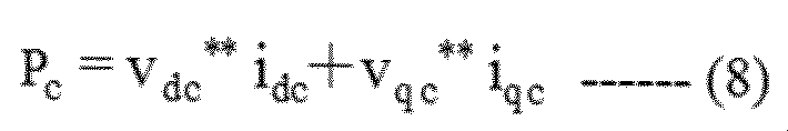
- the first active power calculation unit 72 uses the d-axis and q-axis voltage command values v dc ** and v qc ** and the current detection values i dc and i q c to set the first active power P c (. Calculate according to Eq. 8).
- the output of the first active power calculation unit 72 is passed through the absolute value calculation unit 73 to calculate the absolute value
- the second active power calculation unit 74 has current command values i d * , i q * , output frequency command value ⁇ 1 * for the d-axis and q-axis, and electric circuit constants R1, M, and L 2 of the induction motor 1. Then, using the d-axis secondary magnetic flux estimated value ⁇ 2d ** , the second active power P c ⁇ is calculated according to (Equation 9).
- the output of the second active power calculation unit 74 is passed through the absolute value calculation unit 75, and the absolute value of the second active power P c ⁇
- is the absolute value of the first active power P c
- the LPF77 has a gain with a time constant of T, a secondary magnetic flux command correction value ⁇ 2d0 * is input, and a d-axis secondary magnetic flux correction value ⁇ 2d * is output.
- the d-axis secondary magnetic flux estimated value ⁇ 2d ** is calculated according to (Equation 10).
- the formulas for the d-axis and q-axis voltage command values v dc ** and v dc ** shown in (Equation 2) and the frequency estimation value (speed estimation value) ⁇ r ⁇ shown in (Equation 5) This is a simulation result when there is an error of + 20% in the set value L ⁇ * of the included leakage inductance.
- the upper vertical axis is the load torque T L (Nm)
- the middle vertical axis is the frequency estimate ⁇ r ⁇ (Hz) and the induction motor frequency ⁇ r (Hz)
- the lower vertical axis is the secondary of the d-axis.
- the magnetic flux ⁇ 2d (pu) and its command value ⁇ 2d * (pu) are displayed, and the horizontal axis shows the time (seconds).
- the ramp-shaped load torque T L was started from point A in the figure, and at point B in the figure, it was twice as large as the rated torque (100%) torque, and 200% torque was applied from point B to the right. It is in a state of being. It can be seen that the frequency ⁇ r of the induction motor is faster than the frequency command value ⁇ r * of 30 Hz.
- the frequency estimation value ⁇ r ⁇ is about 30 Hz
- the output frequency command value ⁇ 1 * is calculated by (Equation 6)
- the slip error ⁇ s of the motor is ( ⁇ s ⁇ s ⁇ ).
- Secondary flux phi 2d of d-axis is increased by the slip error [Delta] [omega s.
- the control characteristics characteristics of velocity ⁇
- the rotation speed of the induction motor deviates from the speed command value, resulting in deterioration of the speed characteristics.
- the d-axis voltage command value v dc ** and the q-axis voltage command value v qc ** as the voltage information of the induction motor and the d-axis current detection value i dc as the current information of the induction motor is calculated from (Equation 8).
- the second active power information P c ⁇ which also does not include the information of the leakage inductance L ⁇ , is calculated from (Equation 9).
- is the absolute value of Pc
- Example 1 The control characteristics in Example 1 are shown in FIG. In FIG. 4, the horizontal axis and the vertical axis of FIG. 3 are the same.
- the secondary magnetic flux estimation calculation unit 7 on the d-axis is operated to give a load torque T L similar to that in FIG. Since the secondary magnetic flux ⁇ 2d on the d-axis is estimated with high accuracy ( ⁇ 2d ⁇ ⁇ 2d ** ), the frequency estimation value ⁇ r ⁇ almost matches the frequency ⁇ r of the induction motor, and the effect of this embodiment is obtained. It turns out that is clear.
- the gains (K p , K i ) of the proportional control and the integral control are set to fixed values in the secondary magnetic flux estimation calculation unit 7 of the d-axis, but the output frequency command value is as shown in FIG. It may be changed according to ⁇ 1 * or the current command value i q * of the q axis.
- 7a in FIG. 5 corresponds to the secondary magnetic flux estimation calculation unit 7 on the d-axis of FIG. 7a1, 7a2, 7a3, 7a4, 7a5, 7a7 in FIG. 5 are LPF71, first active power calculation unit 72, absolute value calculation unit 73, second active power calculation unit 74, and absolute value calculation in FIG. 2, respectively. It is the same as the part 75 and LPF77.
- the gains (K p , K i ) of the proportional control and the integral control are changed substantially in proportion to the magnitude of the output frequency command value ⁇ 1 * and the current command value i q * of the q axis.
- of the first active power P c changes to the absolute value
- a voltage detector 21 and a current detector 22 are attached to the power conversion device 20 that drives the induction motor 1, and an encoder 23 is attached to the shaft of the induction motor 1.
- the vector voltage / current component calculation unit 24 contains the three-phase AC voltage detection values (v uc , v vc , v wc ) and the three-phase AC current detection values (i uc , i), which are the outputs of the voltage detector 21.
- vc , i wc ) and the position ⁇ , which is the output of the encoder, are input, and the vector voltage components v dc , v qc , the vector current components i dc , i qc, and the detected value ⁇ r obtained by differentiating the position ⁇ are calculated. ..
- the secondary magnetic flux estimated value ⁇ 2d ⁇ of the d-axis is calculated by using (Equation 11).
- an encoder may be attached to the induction motor 1 to detect the frequency ⁇ r ⁇ . Since the secondary magnetic flux of the d-axis can be estimated with high accuracy, highly accurate control characteristics can be realized by correcting the slip command value.
- FIG. 7 is a configuration diagram of the d-axis secondary magnetic flux estimation calculation unit in the second embodiment.
- the configuration other than the d-axis secondary magnetic flux estimation calculation unit is the same as that in the first embodiment.
- the first active power P c was calculated from the voltage command values v dc ** and v q c ** on the d-axis and q-axis and the current detection values i dc and i q c.
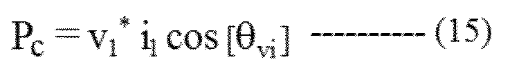
- the amplitude value V 1 * of the voltage command of the three-phase AC as the voltage information of the induction motor, the amplitude value i 1 of the current detection as the current information of the induction motor, and the cosine signal of the phase ⁇ vi are used. , Calculate the active power P c.
- 7b in FIG. 7 corresponds to the secondary magnetic flux estimation calculation unit 7 on the d-axis in FIG. Further, 7b1, 7b3, 7b4, 7b5, 7b6, and 7b7 in FIG. 7 are the LPF71, the absolute value calculation unit 73, the second active power calculation unit 74, the absolute value calculation unit 75, and the PI control unit 76 in FIG. 2, respectively. It is the same as LPF77.
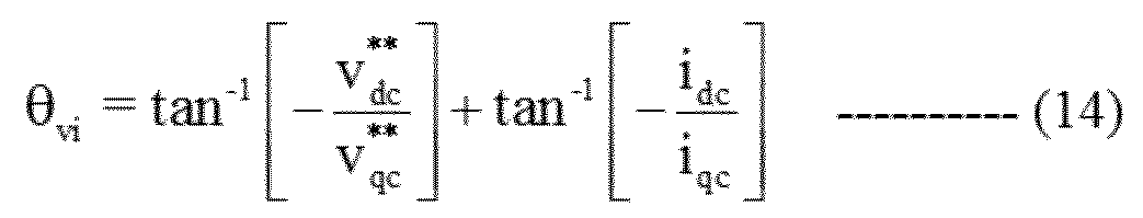
- the first active power calculation unit 7b2 sets the amplitude value V 1 * of the three-phase AC voltage command (Equation 12), the amplitude value i 1 of the current detection value (Equation 13), and the phase ⁇ vi . Obtained from (Equation 14), and the active power P c is calculated using (Equation 15).
- the proportional control and the integral control are substantially proportional to the magnitude of the output frequency command value ⁇ 1 * and the current command value i q * of the q axis.
- the gain (K p , K i ) of may be changed.
- FIG. 8 is a configuration diagram of the d-axis secondary magnetic flux estimation calculation unit in the third embodiment.
- the configuration other than the d-axis secondary magnetic flux estimation calculation unit is the same as that in the first embodiment.
- the first active power P c was calculated from the voltage command values v dc ** and v q c ** on the d-axis and q-axis and the current detection values i dc and i q c.
- the DC voltage value E DC of the DC power supply 3 that supplies the DC voltage to the power converter 2 as the voltage information of the induction motor and the DC current value I that is supplied from the DC power supply 3 as the current information of the induction motor. Calculate the active power P c using DC.
- 7c in FIG. 8 corresponds to the secondary magnetic flux estimation calculation unit 7 on the d-axis in FIG. 7c1, 7c3, 7c4, 7c5, 7c6, 7c7 in FIG. 7 are LPF71, absolute value calculation unit 73, second active power calculation unit 74, absolute value calculation unit 75, PI control unit 76, LPF77 in FIG. Is the same as.
- the active power P c is calculated using (Equation 16) using the DC voltage detection value E DC and the DC current detection value I DC of the power converter.
- the gains of the proportional control and the integral control are substantially proportional to the magnitude of the output frequency command value ⁇ 1 * and the current command value i q * of the q axis, as in FIG. (K p , K i ) may be changed.
- FIG. 9 is a configuration diagram of the d-axis secondary magnetic flux estimation calculation unit in the fourth embodiment.
- the configuration other than the d-axis secondary magnetic flux estimation calculation unit is the same as that in the first embodiment.
- two active power information is used, but from this embodiment, two active power information is used.
- 7d in FIG. 9 corresponds to the secondary magnetic flux estimation calculation unit 7 on the d-axis in FIG. Further, 7d1, 7d3, 7d5, 7d6, and 7d7 in FIG. 7 are the same as L.P.F71, absolute value calculation unit 73, absolute value calculation unit 75, PI control unit 76, and L.P.F77 in FIG.
- the first reactive power calculation unit 7d2 has a d-axis voltage command value v dc ** and a q-axis voltage command value v qc ** as the voltage information of the induction motor, and a current detection value as the current information of the induction motor.
- the first reactive power Q c is calculated according to (Equation 17).
- the output of the first ineffective power calculation unit 7d2 is passed through the absolute value calculation unit 7d3 to calculate the absolute value
- the second ineffective power calculation unit 7d4 has current command values i d * , i q * , output frequency command value ⁇ 1 * for the d-axis and q-axis, and electric circuit constants R1, M, and L 2 of the induction motor 1. Then, using the d-axis magnetic flux estimated value ⁇ 2d ** , the second ineffective power Q c ⁇ is calculated according to (Equation 18).
- the output of the second invalid power calculation unit 7d4 is passed through the absolute value calculation unit 7d5, and the absolute value
- is the absolute value of the first reactive power Q c
- the LPF7d7 has a gain with a time constant of T, a d-axis secondary magnetic flux command correction value ⁇ 2d0 * is input, and a d-axis secondary magnetic flux correction value ⁇ 2d * is calculated.
- the d-axis secondary magnetic flux estimated value ⁇ 2d ** is calculated according to the above (Equation 10).
- is the absolute value of the first reactive power Q c
- the gain of the proportional control and the integral control is substantially proportional to the magnitude of the output frequency command value ⁇ 1 * and the current command value i q * of the q axis. (K p , K i ) may be changed. By doing so, it is possible to realize highly accurate control characteristics in a shorter time even in a low speed range to a high speed range and from a light load to a heavy load.
- FIG. 10 is a configuration diagram of the d-axis secondary magnetic flux estimation calculation unit in the fifth embodiment.
- the configuration other than the d-axis secondary magnetic flux estimation calculation unit is the same as that in the first embodiment.
- the first reactive power Q c was calculated from the voltage command values v dc ** and v q c ** on the d-axis and q-axis and the current detection values i dc and i q c.
- the amplitude value V 1 * of the voltage command of the three-phase AC as the voltage information of the induction motor, the amplitude value i 1 of the current detection as the current information of the induction motor, and the phase ⁇ vi are used and invalid. Calculate the power Q c.
- 7e in FIG. 10 corresponds to the secondary magnetic flux estimation calculation unit 7d on the d-axis in FIG. Further, 7e1, 7e3, 7e4, 7e5, 7e6, 7e7 in FIG. 10 are LPF7d1, absolute value calculation unit 7d3, second invalid power calculation unit 7d4, absolute value calculation unit 7d5, PI control unit 7d6, LP in FIG. It is the same as F7d7.
- the amplitude value V 1 * of the voltage command of the three-phase AC is the above-mentioned (Equation 12)
- the amplitude value i 1 of the current detection value is the above-mentioned (Equation 13)
- the sine signal of the phase ⁇ vi is calculated by (Equation 19).
- the gain of the proportional control and the integral control is substantially proportional to the magnitude of the output frequency command value ⁇ 1 * and the current command value i q * of the q axis. (K p , K i ) may be changed. By doing so, it is possible to realize highly accurate control characteristics in a shorter time even in a low speed range to a high speed range and from a light load to a heavy load.
- FIG. 11 is a configuration diagram of a system having a power conversion device and an induction motor according to the sixth embodiment.
- This embodiment is an application of this embodiment to an induction motor drive system.
- the induction motor 1, the coordinate conversion unit 5, the speed control calculation unit 6, the d-axis secondary magnetic flux estimation calculation unit 7, the vector control calculation unit 8, and the frequency / phase estimation calculation unit 9 have the configuration of FIG. It is the same.
- the induction motor 1, which is a component of FIG. 1, is driven by the power conversion device 20.
- the power conversion device 20 is divided into software 20a and hardware.
- the coordinate conversion unit 5, the speed control calculation unit 6, the d-axis secondary magnetic flux estimation calculation unit 7, the vector control calculation unit 8, the frequency / phase estimation calculation unit 9, and the coordinate conversion unit 10 of FIG. 1 are software 20a.
- the same parts as those in FIG. 1 of the software 20a in FIG. 11 are partially omitted.
- the power converter 2, DC power supply 3, and current detector 4 of FIG. 1 are mounted as hardware. Further, a predetermined proportional gain 31 and a predetermined integrated gain 32 of the software 20a are obtained by a higher-level device such as a digital operator 20b that operates and displays the power conversion device 20 and a personal computer 28, a tablet 29, and a smartphone 30. It can be set in the recording unit of the control unit or the recorded gain can be changed.
- a higher-level device such as a digital operator 20b that operates and displays the power conversion device 20 and a personal computer 28, a tablet 29, and a smartphone 30. It can be set in the recording unit of the control unit or the recorded gain can be changed.
- the proportional gain Kp1 or the integrated gain Ki1 of the PI control unit 76 in the d-axis secondary magnetic flux estimation calculation unit 7 can be set externally or the gain can be changed.
- the predetermined proportional gain 31 and the predetermined integrated gain 32 may be set on the fieldbus of the programmable logic controller, the local area network connected to the computer, or the control device.
- Example 6 is disclosed using Example 1, any of Examples 2 to 5 may be used.
- Example 5 In Example 5 from Example 1, * current command value i d, i q * and the current detection value i dc, i voltage correction value from the qc Delta] v dc, to create a Delta] v qc, the voltage correction value and a vector control The calculation shown in (Equation 3) of adding the voltage reference values was performed.
- K pd1 is the proportional gain of d-axis current control
- K id1 is the integrated gain of d-axis current control
- K pq1 is the proportional gain of q-axis current control
- K iq1 is the integrated gain of q-axis current control.
- T d is the d-axis electrical time constant (L ⁇ / R)
- T q is the q-axis electrical time constant (L ⁇ / R).
- K pd2 is the proportional gain of the d-axis current control
- K id2 is the integrated gain of the d-axis current control
- K pq2 the proportional gain of the q-axis current control
- K iq2 the integrated gain of the q-axis current control.
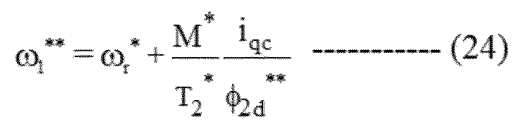
- the d-axis current command value i d *, the q-axis current detection value i qc primary delay signal i qctd , the frequency command value ⁇ r *, and the electric circuit constants of the induction motor 1 are shown in (Equation 24).
- the output frequency command value ⁇ 1 ** and the vector control operation shown in (Equation 25) may be performed.
- i qctd is a signal that has passed i qc through a first-order lag filter.
- the frequency / phase estimation calculation unit 9 calculates the frequency estimation value according to (Equation 5). Current control and velocity estimation may be used together in q-axis current control. The frequency estimate ⁇ r ⁇ is calculated as shown in (Equation 26).
- K pq 3 is the proportional gain of current control
- K iq 3 is the integrated gain of current control
- the frequency / phase estimation calculation unit 9 calculated the frequency estimation value according to (Equation 5) or (Equation 26), but an encoder may be attached to the induction motor 1 and the frequency detection value may be calculated from the encoder signal.
- the switching element constituting the power converter 2 is a wide band such as SiC (silicon carbide) or GaN (galium nitride) even if it is a Si (silicon) semiconductor element. It may be a gap semiconductor element.
Landscapes
- Engineering & Computer Science (AREA)
- Power Engineering (AREA)
- Control Of Ac Motors In General (AREA)
Abstract
電力変換装置は、スイッチング素子を有する電力変換器と、誘導モータの電圧情報および電流情報から電力変換器を制御する制御部とを有し、 制御部は、誘導モータの電圧情報と電流情報から演算した第1の電力情報を演算し、誘導モータの電気回路定数、電流指令値、出力周波数指令値および磁束推定値から第2の電力情報を演算し、第2の電力情報が、第1の電力情報に追従するように磁束推定値を演算する。
Description
本発明は、誘導モータを駆動する電力変換装置に関する。
誘導モータの高精度な制御方法としては、特許文献1に記載のように、電力変換部から誘導モータへの出力電圧と電動機の巻線抵抗により生じる電圧降下量の差分に基づいて、誘導モータの固定子磁束ベクトルを推定する技術の記載がある。
特許文献1に記載された技術では、静止座標系α、βを使い、磁束ベクトルを推定する。αβの各軸成分では、磁束ベクトルは正弦波の形状に変化する。そのため、高速域では、正弦波の変化を検出するサンプリング周期が十分に短くないと、正弦波の振幅の値を正確に検出できない。しかし、サンプリング周期には限界が有るので、その限界を超える高速域では磁束の推定の精度を高めるのは困難である。
磁束推定の精度が十分ではないことにより、特許文献1では、速度指令値と実際の誘導モータの回転速度にずれが生じ速度特性が悪くなることが考えられる。また、高速域で磁束を推定する場合に、電気回路定数の誤差で速度特性が悪くなるという課題がある。
本発明の目的は、高速域で速度特性が悪化することを防ぐ電力変換装置を提供することにある。
本発明の好ましい一例としては、スイッチング素子を有する電力変換器と、
誘導モータの電圧情報および電流情報から前記電力変換器を制御する制御部とを有し、
前記制御部は、
前記誘導モータの電圧情報と電流情報から演算した第1の電力情報を演算し、
前記誘導モータの電気回路定数、電流指令値、出力周波数指令値および磁束推定値から第2の電力情報を演算し、
前記第2の電力情報が、前記第1の電力情報に追従するように前記磁束推定値を演算する電力変換装置である。
誘導モータの電圧情報および電流情報から前記電力変換器を制御する制御部とを有し、
前記制御部は、
前記誘導モータの電圧情報と電流情報から演算した第1の電力情報を演算し、
前記誘導モータの電気回路定数、電流指令値、出力周波数指令値および磁束推定値から第2の電力情報を演算し、
前記第2の電力情報が、前記第1の電力情報に追従するように前記磁束推定値を演算する電力変換装置である。
本発明によれば、高速域で速度特性の悪化を防ぐことができる。
以下、図面を用いて実施例を詳細に説明する。
図1は、実施例1における電力変換装置の構成図を示す。誘導モータ1は、磁束軸(d軸)成分の電流により発生する磁束と、磁束軸に直行するトルク軸(q軸)成分の電流によりトルクを発生する。
電力変換器2は、スイッチング素子としての半導体素子を備える。電力変換器2は、3相交流の電圧指令値vu
*、vv
*、vw
*を入力し、3相交流の電圧指令値vu
*、vv
*、vw
*に比例した電圧値を出力する。電力変換器2の出力に基づいて、誘導モータ1の出力電圧値と出力周波数値を可変する。スイッチング素子としてIGBTを使うようにしてもよい。
直流電源3は、電力変換器2に直流電圧および直流電流を供給する。
電流検出器4は、誘導モータ1の3相の交流電流iu、iv、iwの検出値であるiuc、ivc、iwcを出力する。また電流検出器4は、誘導モータ1の3相の内の2相、例えば、u相とw相の交流電流を検出し、v相の交流電流は、交流条件(iu+iv+iw=0)から、iv=-(iu+iw)として求めてもよい。本実施例では、電流検出器4は、電力変換装置内に設けた例を示したが、電力変換装置の外部に設けてもよい。
制御部は、以下に説明する座標変換部5、速度制御演算部6、d軸の二次磁束推定演算部7、ベクトル制御演算部8、周波数・位相推定演算部9、座標変換部10を備える。そして、制御部は、電力変換器2を制御する。
制御部は、マイコン(マイクロコンピュータ)やDSP(Digital Signal Processor)などの半導体集積回路(演算制御手段)によって構成される。制御部は、いずれかまたは全部をASIC(Application Specific Integrated Circuit)やFPGA(Field Programmable Gate Array)などのハードウェアで構成することができる。
次に、電力変換器2を制御する制御部の各構成要素について、説明する。
座標変換部5は、3相の交流電流iu、iv、iwの交流電流検出値iuc、ivc、iwcと位相演算値θdcからd軸の電流検出値idcおよびq軸の電流検出値iqcを出力する。
速度制御演算部6は、周波数指令値ωr
*と周波数推定値ωr
^に基づいて演算したq軸の電流指令値iq
*を出力する。
d軸の二次磁束推定演算部7は、d軸およびq軸の電圧指令値vdc
**、vqc
**、電流検出値idc、iqc、電流指令値id
*、iq
*と出力周波数指令値ω1
*に基づいて演算したd軸の磁束推定値φ2d
**を出力する。
ベクトル制御演算部8は、d軸の二次磁束推定値φ2d
**、d軸およびq軸の電流指令値id
*、iq
*、電流検出値idc、iqcと出力周波数指令値ω1
*に基づいて演算したd軸およびq軸の電圧指令値vdc
**、vqc
**を出力する。
周波数・位相推定演算部9は、q軸の電圧指令値vqc
**、d軸の電流指令値id
*、q軸の電流指令値iq
*および電流検出値iqcとd軸の二次磁束推定値φ2d
**に基づいて演算した周波数推定値ωr
^、出力周波数指令値ω1
*と位相演算値θdcを出力する。
座標変換部10は、d軸の電圧指令値vdc
**とq軸の電圧指令値vqc
**と、位相演算値θdcから3相交流の電圧指令値vu
*、vv
*、vw
*を出力する。
最初に、d軸の二次磁束推定演算部7を用いた場合のセンサレスベクトル制御の基本動作について説明する。
速度制御演算部6は、周波数指令値ωr
*に周波数推定値ωr
^が追従するように、比例制御と積分制御により(数1)に従いトルク電流指令であるq軸の電流指令値iq
*を演算する。

ベクトル制御演算部8では、第1に、d軸の二次磁束推定値φ2d
**、d軸およびq軸の電流指令値id
*、iq
*と出力周波数指令値ω1
*を用いて(数2)に従いd軸およびq軸の電圧指令値vdc
*、vqc
*を出力する。

第2に、d軸およびq軸の電流指令値id
*、iq
*に、各成分の電流検出値idc、iqcが追従するよう比例制御と積分制御により、(数3)に従いd軸およびq軸の電圧補正値Δvdc、Δvqcを演算する。

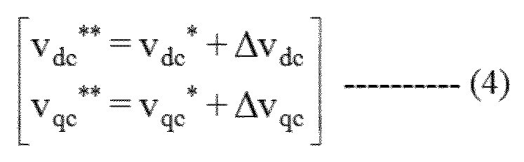
さらに(数4)に従い、d軸およびq軸の電圧指令値vdc
**、vdc
**を演算する。
周波数・位相推定演算部9では、q軸の電圧指令値vqc
**、d軸の電流指令値id
*、q軸の電流指令値iq
*および電流検出値iqcとd軸の二次磁束推定値φ2d
**に基づいて、(数5)に従い周波数推定値ωr
^を、(数6)に従い出力周波数指令値ω1
*を、(数7)に従い位相演算値θdcをそれぞれ演算する。
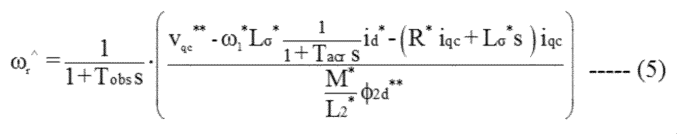
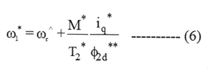

図2に本実施例の特徴であるd軸の二次磁束推定演算部7のブロックを示す。
L.P.F(Low Pass Filter)71は、ゲインが相互インダクタンスM、時定数が二次時定数T2であり、d軸の電流指令値id
*が入力され、d軸の二次磁束指令値φ2d
*を演算する。
第1の有効電力演算部72は、d軸およびq軸の電圧指令値vdc
**、vqc
**と電流検出値idc、iqcを用いて、第1の有効電力Pcを(数8)に従い演算する。
力行/回生の両方の運転モードに対応するため、第1の有効電力演算部72の出力を絶対値演算部73に通して、第1の有効電力Pcの絶対値|Pc|を演算する。
第2の有効電力演算部74は、d軸およびq軸の電流指令値id
*、iq
*、出力周波数指令値ω1
*、誘導モータ1の電気回路定数であるR1、M、L2と、d軸の二次磁束推定値φ2d
**を用いて、第2の有効電力Pc
^を(数9)に従い演算する。

力行/回生の両方の運転モードに対応するため、第2の有効電力演算部74の出力を絶対値演算部75に通して、第2の有効電力Pc
^の絶対値| Pc
^|を演算する。
PI制御部76は、第2の有効電力Pc
^の絶対値|Pc
^|が、第1の有効電力Pcの絶対値|Pc|に追従するように、P(比例)制御とI(積分)制御を行い、d軸の二次磁束指令補正値Δφ2d0
*を演算する。
L.P.F77は、時定数がTのゲインを持ち、二次磁束指令補正値Δφ2d0
*が入力され、d軸の二次磁束補正値Δφ2d
*を出力する。前記Δφ2d
*とd軸の二次磁束指令値φ2d
*を用いて、d軸の二次磁束推定値φ2d
**を(数10)に従い演算する。

つぎに、本実施例が高精度な制御特性となる原理について説明する。
図3は、d軸の二次磁束推定演算部7を用いない(Δφ2d
*=0)比較例としての制御特性を示す。(数2)に示すd軸およびq軸の電圧指令値vdc
**、vdc
**の演算式と、(数5)に示す周波数推定値(速度推定値)ωr^の演算式に含まれる漏れインダクタンスの設定値Lσ
*に、+20%の誤差がある場合のシミュレーション結果である。
上段の縦軸は負荷トルクTL(N・m)、中段の縦軸は周波数推定値ωr^(Hz)と誘導モータの周波数ωr(Hz)、下段の縦軸はd軸の二次磁束φ2d(p.u)とその指令値φ2d
*(p.u)を、横軸は時間(秒)を表示している。
ランプ状の負荷トルクTLを図中のA点から与え始め、図中のB点で定格トルク(100%)トルクの2倍の大きさとなり、B点より右以降は200%トルクを与えたままの状態である。誘導モータの周波数ωrが周波数指令値ωr
*である30Hzより増速していることがわかる。
一方、周波数推定値ωr
^は約30Hzであり、(数6)により出力周波数指令値ω1
*を演算するため、周波数の推定誤差はΔω=(ωr―ωr
^)であり、誘導モータのすべり誤差Δωsは(ωs―ωs
^)となる。このすべり誤差Δωsによりd軸の二次磁束φ2dが増加してしまう。そのようになると漏れインダクタンスの設定値Lσ
*によっては制御特性(速度ωの特性)が劣化する。つまり誘導モータの回転速度が速度指令値からずれるという速度特性の悪化が生じる問題があった。
本実施例では、誘導モータの電圧情報としてのd軸の電圧指令値vdc
**およびq軸の電圧指令値vqc
**と、誘導モータの電流情報としてのd軸の電流検出値idc、q軸の電流検出値iqcを用いて、電気回路定数である漏れインダクタンスLσの情報を含まない第1の有効電力Pcを(数8)より演算する。
また、d軸の電流指令値id
*およびq軸の電流指令値iq
*、出力周波数指令値ω1
*、誘導モータの電気回路定数R1、M、L2とd軸の二次磁束の推定値φ2d
**を用いて、こちらも漏れインダクタンスLσの情報を含まない第2の有効電力情報Pc
^を(数9)より演算する。
上記のPc
^の絶対値|Pc
^|が、Pcの絶対値|Pc|に追従するように前記φ2d
**を推定し、推定値φ2d
^をベクトル制御演算部8、周波数・位相推定演算部9に用いることで、制御特性を改善することができる。
実施例1における制御特性を図4に示す。図4は、図3の横軸と縦軸は同じである。d軸の二次磁束推定演算部7を動作させ、図3と同様な負荷トルクTLを与えている。d軸の二次磁束φ2dを高精度に推定する(φ2d≒φ2d
**)ため、周波数推定値ωr
^は誘導モータの周波数ωrにほぼ一致しており、本実施例の効果が明白であることがわかる。
また上記の実施例では、d軸の二次磁束推定演算部7において、比例制御と積分制御のゲイン(Kp、Ki)を固定値としているが、図5に示すように出力周波数指令値ω1
*やq軸の電流指令値iq
*に応じて変化させてもよい。
図5における7aは図2のd軸の二次磁束推定演算部7に相当する。図5における7a1、7a2、7a3、7a4、7a5、7a7は、それぞれ図2のL.P.F71、第1の有効電力演算部72、絶対値演算部73、第2の有効電力演算部74、絶対値演算部75、L.P.F77と同一である。
図5のPI制御部7a6において、出力周波数指令値ω1
*の大きさやq軸の電流指令値iq
*に略比例して、比例制御と積分制御のゲイン(Kp、Ki)を変化させることで、第1の有効電力Pcの絶対値|Pc|が、第2の有効電量Pc
^の絶対値|Pc
^|に、周波数や電流値に応じて変化する。つまり低速域から高速域、軽負荷から重負荷においても、より短時間で高精度な制御特性を実現できる。
ここで、図6を用いて本実施例を採用した場合の検証方法について説明する。誘導モータ1を駆動する電力変換装置20に、電圧検出器21、電流検出器22を取り付け、誘導モータ1のシャフトにはエンコーダ23を取り付ける。
ベクトル電圧・電流成分の計算部24には、電圧検出器21の出力である三相交流の電圧検出値(vuc、vvc、vwc)、三相交流の電流検出値(iuc、ivc、iwc)とエンコーダの出力である位置θが入力され、ベクトル電圧成分のvdc、vqc、ベクトル電流成分のidc、iqcと、位置θを微分した検出値ωrを演算する。
各部波形の観測部25では、(数11)を用いて、d軸の二次磁束推定値φ2d
^を演算する。

電力変換器2に設定する漏れインダクタンスLσ
*の大きさを変更すると、上記φ2d
^の大きさが変更され、検出値ωrがほぼ指令値に一致していれば、本実施例を採用していることが明白となる。
なお、本実施例では周波数推定値ωr
^を演算しているが、誘導モータ1にエンコーダを取り付けて、周波数ωrを検出するようにしてもよい。d軸の二次磁束を高精度に推定できるので、すべり指令値を修正することで高精度な制御特性を実現できる。
図7は、実施例2におけるd軸の二次磁束推定演算部の構成図である。本実施例は、d軸の二次磁束推定演算部以外の構成は実施例1と同じである。実施例1では、d軸およびq軸の電圧指令値vdc
**、vqc
**と電流検出値idc、iqcから、第1の有効電力Pcを演算した。
実施例2では、誘導モータの電圧情報としての三相交流の電圧指令の振幅値V1
*と、誘導モータの電流情報としての電流検出の振幅値i1および位相θviの余弦信号を用いて、有効電力Pcを演算する。
図7における7bは、図2におけるd軸の二次磁束推定演算部7に相当するものである。また図7における7b1、7b3、7b4、7b5、7b6、7b7は、それぞれ図2のL.P.F71、絶対値演算部73、第2の有効電力演算部74、絶対値演算部75、PI制御部76、L.P.F77と同一である。
図7において、第1の有効電力演算部7b2では三相交流の電圧指令の振幅値V1
*を(数12)、電流検出値の振幅値i1を(数13)、および位相θviを(数14)より求め、(数15)を用いて有効電力Pcを演算する。


本実施例を用いても実施例1と同様に、高精度な制御特性を実現することができる。
また、実施例2においても、図5と同様に、PI制御部7b6において、出力周波数指令値ω1
*の大きさやq軸の電流指令値iq
*に略比例して、比例制御と積分制御のゲイン(Kp、Ki)を変化させるようにしてもよい。そのようにすることで、低速域から高速域、軽負荷から重負荷においても、より短時間で高精度な制御特性を実現できる。
図8は、実施例3におけるd軸の二次磁束推定演算部の構成図である。本実施例は、d軸の二次磁束推定演算部以外の構成は実施例1と同じである。実施例1では、d軸およびq軸の電圧指令値vdc
**、vqc
**と電流検出値idc、iqcから、第1の有効電力Pcを演算した。
実施例3では、誘導モータの電圧情報として電力変換器2に直流電圧を供給する直流電源3の直流電圧値EDCと、誘導モータの電流情報として、直流電源3から供給される直流電流値IDCを用いて有効電力Pcを演算する。
図8における7cは、図2におけるd軸の二次磁束推定演算部7に相当するものである。図7における7c1、7c3、7c4、7c5、7c6、7c7は、図2のL.P.F71、絶対値演算部73、第2の有効電力演算部74、絶対値演算部75、PI制御部76、L.P.F77と同一である。
図7において、7c2では電力変換器の直流電圧検出値EDC、直流電流検出値IDCを用いて、有効電力Pcを(数16)を用いて演算する。

本実施例を用いても、実施例1と同様に、高精度な制御特性を実現することができる。
実施例3においても、図5と同様に、PI制御部7c6において、出力周波数指令値ω1
*の大きさやq軸の電流指令値iq
*に略比例して、比例制御と積分制御のゲイン(Kp、Ki)を変化させるようにしてもよい。
図9は、実施例4におけるd軸の二次磁束推定演算部の構成図である。本実施例は、d軸の二次磁束推定演算部以外の構成は実施例1と同じである。実施例1では、2つの有効電力情報を用いたが、本実施例からは、2つの無効電力情報を用いる。
図9における7dは、図2におけるd軸の二次磁束推定演算部7に相当するものである。また図7における7d1、7d3、7d5、7d6、7d7は、図2のL.P.F71、絶対値演算部73、絶対値演算部75、PI制御部76、L.P.F77と同一である。
第1の無効電力演算部7d2は、誘導モータの電圧情報としてのd軸の電圧指令値vdc
**およびq軸の電圧指令値vqc
**と、誘導モータの電流情報としての電流検出値idc、iqcを用いて、第1の無効電力Qcを(数17)に従い演算する。

力行/回生の両方の運転モードに対応するため、第1の無効電力演算部7d2の出力を絶対値演算部7d3に通して、第1の無効電力Qcの絶対値|Qc|を演算する。
第2の無効電力演算部7d4は、d軸およびq軸の電流指令値id
*、iq
*、出力周波数指令値ω1
*、誘導モータ1の電気回路定数であるR1、M、L2と、d軸の磁束推定値φ2d
**を用いて、第2の無効電力Qc
^を(数18)に従い演算する。

力行/回生の両方の運転モードに対応するため、第2の無効電力演算部7d4の出力を絶対値演算部7d5に通して、第2の無効電力Qc
^の絶対値|Qc
^|を演算する。
PI制御部7d6は、第2の無効電力Qc
^の絶対値|Qc
^|が第1の無効電力Qcの絶対値|Qc|に追従するように、P(比例)+I(積分)制御を行い、d軸の二次磁束指令補正値Δφ2d0
*を演算する。
L.P.F7d7は、時定数がTのゲインを持ち、d軸の二次磁束指令補正値Δφ2d0
*が入力され、d軸の二次磁束補正値Δφ2d
*を演算する。前記Δφ2d
*とd軸の二次磁束指令値φ2d
*を用いて、d軸の二次磁束推定値φ2d
**を前記の(数10)に従い演算する。
本実施例は、第2の無効電力Qc
^の絶対値|Qc
^|が、第1の無効電力Qcの絶対値|Qc|に追従するように、d軸の二次磁束指令値φ2d
*を修正することにより、電気回路定数である抵抗の設定値R1
*に誤差があっても、力行/回生の運転モードに係わらず高精度な制御特性を実現することができる。
実施例4においても、図5と同様に、PI制御部7d6において、出力周波数指令値ω1
*の大きさやq軸の電流指令値iq
*に略比例して、比例制御と積分制御のゲイン(Kp、Ki)を変化させるようにしてもよい。そのようにすることで、低速域から高速域、軽負荷から重負荷においても、より短時間で高精度な制御特性を実現できる。
図10は、実施例5におけるd軸の二次磁束推定演算部の構成図である。本実施例は、d軸の二次磁束推定演算部以外の構成は実施例1と同じである。実施例4では、d軸およびq軸の電圧指令値vdc
**、vqc
**と電流検出値idc、iqcから、第1の無効電力Qcを演算した。
実施例5では、誘導モータの電圧情報としての三相交流の電圧指令の振幅値V1
*と、誘導モータの電流情報としての電流検出の振幅値i1、および位相θviを用いて、無効電力Qcを演算する。
図10における7eは、図9におけるd軸の二次磁束推定演算部7dに相当するものである。また図10における7e1、7e3、7e4、7e5、7e6、7e7は、図9のL.P.F7d1、絶対値演算部7d3、第2の無効電力演算部7d4、絶対値演算部7d5、PI制御部7d6、L.P.F7d7と同一である。
図10において、7e2では三相交流の電圧指令の振幅値V1
*を前述の(数12)、電流検出値の振幅値i1を前述の(数13)、および位相θviの正弦信号を用いて、無効電力Qcを(数19)により演算する。

本実施例を用いても、実施例4と同様に、抵抗の設定値R1
*に誤差があっても、力行/回生の両方のトルクモードに係わらず、高精度な制御特性を実現することができる。
実施例5においても、図5と同様に、PI制御部7e6において、出力周波数指令値ω1
*の大きさやq軸の電流指令値iq
*に略比例して、比例制御と積分制御のゲイン(Kp、Ki)を変化させるようにしてもよい。そのようにすることで、低速域から高速域、軽負荷から重負荷においても、より短時間で高精度な制御特性を実現できる。
図11は、実施例6における電力変換装置と誘導モータを有するシステムの構成図である。本実施例は、誘導モータ駆動システムに本実施例を適用したものである。図11において、誘導モータ1、座標変換部5、速度制御演算部6、d軸の二次磁束推定演算部7、ベクトル制御演算部8、周波数・位相推定演算部9は、図1の構成と同一である。
図1の構成要素である誘導モータ1は、電力変換装置20により駆動される。電力変換装置20は、ソフトウェア20aとハードウェアに分かれている。図1の座標変換部5、速度制御演算部6、d軸の二次磁束推定演算部7、ベクトル制御演算部8、周波数・位相推定演算部9、座標変換部10がソフトウェア20aである。図11のソフトウェア20aの図1と同じところは記載を一部省略した。
図1の電力変換器2、直流電源3、電流検出器4がハードウェアとして実装されている。また、電力変換装置20の操作や表示をするデジタル・オペレータ20bや、パーソナル・コンピュータ28、タブレット29、スマートフォン30などの上位装置により、ソフトウェア20aの所定の比例ゲイン31、所定の積分ゲイン32を、制御部の記録部に設定するか、記録しておいたゲインの変更をすることができる。
例えば、d軸の二次磁束推定演算部7におけるPI制御部76の比例ゲインKp1もしくは積分ゲインKi1を、外部から設定するか、もしくは、そのゲインを変更することができる。
本実施例を誘導モータ駆動システムに適用すれば、速度センサレスベクトル制御において高精度な制御特性を実現することができる。また所定の比例ゲイン31、所定の積分ゲイン32は、プログラマブル・ロジック・コントローラ、コンピュータと接続するローカル・エリア・ネットワーク、制御装置のフィールドバス上で設定してもよい。
実施例6は実施例1を用いて開示してあるが、実施例2から実施例5のいずれを用いても良い。
実施例1から実施例5においては、電流指令値id
*、iq
*と電流検出値idc、iqcから電圧修正値Δvdc、Δvqcを作成し、この電圧修正値とベクトル制御の電圧基準値を加算する(数3)に示す演算を行った。
電流指令値id
*、iq
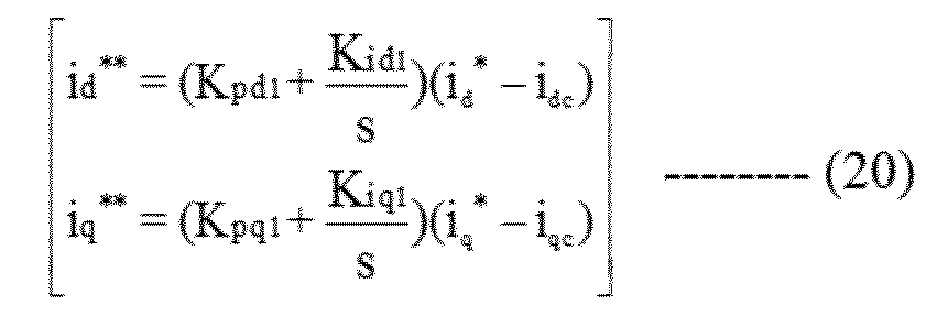
*と電流検出値idc、iqcからベクトル制御演算に使用する(数20)に示す中間的な電流指令値id
**、iq
**を作成し、出力周波数指令値ω1
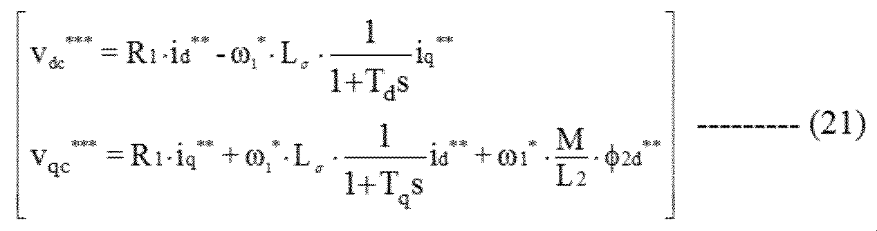
*および誘導モータ1の電気回路定数を用いて(数21)に示すベクトル制御演算を行ってもよい。
電流指令値id
**、iq
*と電流検出値idc、iqcから、ベクトル制御演算に使用するd軸の比例演算成分の電圧修正値Δvd_p
*、d軸の積分演算成分の電圧修正値Δvd_i
*、q軸の比例演算成分の電圧修正値Δvq_p
*、q軸の積分演算成分の電圧修正値Δvq_i
*を(数22)により作成し、出力周波数指令値ω1
*および誘導モータ1の電気回路定数を用いた(数23)に示すベクトル制御演算を行ってもよい。


d軸の電流指令値id
*およびq軸の電流検出値iqcの一次遅れ信号iqctd、周波数指令値ωr
*と、誘導モータ1の電気回路定数を用いて、(数24)に示す出力周波数指令値ω1
**と、(数25)に示すベクトル制御演算を行ってもよい。

実施例1から実施例5においては、周波数・位相推定演算部9では(数5)に従い周波数推定値を演算していた。q軸電流制御で電流制御と速度推定を併用しても良い。(数26)に示すように周波数推定値ωr
^^を演算する。

さらに周波数・位相推定演算部9において、(数5)あるいは(数26)に従い周波数推定値を演算したが、誘導モータ1にエンコーダを取りつけ、エンコーダ信号から周波数検出値を演算しても良い。
実施例1から実施例6において、電力変換器2を構成するスイッチング素子としては、Si(シリコン)半導体素子であっても、SiC(シリコンカーバイト)やGaN(ガリュームナイトライド)などのワイドバンドギャップ半導体素子であってもよい。
1…誘導モータ、2…電力変換器、3…直流電源、4…電流検出器、5…座標変換部、6…速度制御演算部、7…d軸の二次磁束推定演算部、8…ベクトル制御演算部、9…周波数・位相推定演算部、10…座標変換部
Claims (12)
- スイッチング素子を有する電力変換器と、
誘導モータの電圧情報および電流情報から前記電力変換器を制御する制御部とを有し、
前記制御部は、
前記誘導モータの電圧情報と電流情報から演算した第1の電力情報を演算し、
前記誘導モータの電気回路定数、電流指令値、出力周波数指令値および磁束推定値から第2の電力情報を演算し、
前記第2の電力情報が、前記第1の電力情報に追従するように前記磁束推定値を演算する
電力変換装置。 - 請求項1に記載の電力変換装置において、
前記第1の電力情報および前記第2の電力情報は、有効電力である電力変換装置。 - 請求項2に記載の電力変換装置において、
前記制御部は、
d軸およびq軸の電圧指令値とd軸およびq軸の検出電流から前記第1の電力情報を演算し、
前記誘導モータの前記電気回路定数、d軸およびq軸の前記電流指令値、前記出力周波数指令値およびd軸の前記磁束推定値から前記第2の電力情報を演算し、
前記第2の電力情報が、前記第1の電力情報に追従するようにd軸の前記磁束推定値を演算する
電力変換装置。 - 請求項2に記載の電力変換装置において、
前記制御部は、
三相交流の電圧指令値および電流検出値の振幅値から前記第1の電力情報を演算し、
前記誘導モータの電気回路定数、d軸およびq軸の前記電流指令値、前記出力周波数指令値およびd軸の前記磁束推定値から前記第2の電力情報を演算し、
前記第2の電力情報が、前記第1の電力情報に追従するようにd軸の前記磁束推定値を演算する
電力変換装置。 - 請求項2に記載の電力変換装置において、
前記制御部は、
前記電力変換器の直流電圧値と直流電流値から前記第1の電力情報を演算し、
前記誘導モータの前記電気回路定数、d軸およびq軸の前記電流指令値、前記出力周波数指令値およびd軸の前記磁束推定値から前記第2の電力情報を演算し、
前記第2の電力情報が、前記第1の電力情報に追従するようにd軸の前記磁束推定値を演算する
電力変換装置。 - 請求項1に記載の電力変換装置において、
前記第1の電力情報および前記第2の電力情報は、無効電力である電力変換装置。 - 請求項6に記載の電力変換装置において、
前記制御部は、
d軸およびq軸の電圧指令値とd軸およびq軸の検出電流から前記第1の電力情報を演算し、
前記誘導モータの前記電気回路定数、d軸およびq軸の前記電流指令値、前記出力周波数指令値およびd軸の前記磁束推定値から前記第2の電力情報を演算し、
前記第2の電力情報が、前記第1の電力情報に追従するようにd軸の前記磁束推定値を演算する
電力変換装置。 - 請求項6に記載の電力変換装置において、
前記制御部は、
三相交流の電圧指令値および電流検出値の振幅値から前記第1の電力情報を演算し、
前記誘導モータの前記電気回路定数、d軸およびq軸の前記電流指令値、前記出力周波数指令値およびd軸の前記磁束推定値から前記第2の電力情報を演算し、
前記第2の電力情報が、前記第1の電力情報に追従するようにd軸の前記磁束推定値を演算する
電力変換装置。 - 請求項1に記載の電力変換装置において、
前記制御部は、
前記第1の電力情報と前記第2の電力情報との偏差を零とするように比例制御と積分制御により前記磁束推定値を演算する
電力変換装置。 - 請求項9に記載の電力変換装置において、
前記誘導モータの前記出力周波数指令値あるいはq軸の前記電流指令値の少なくともどちらか一方に基づいて、
前記比例制御と前記積分制御の制御ゲインを修正する
電力変換装置。 - 請求項1に記載の電力変換装置において、
デジタル・オペレータやパーソナル・コンピュータあるいはタブレット、スマートフォン機器から、
比例制御あるいは積分制御に設定する制御ゲインを、記録部に設定するか、もしくは設定した制御ゲインを変更する
電力変換装置。 - 請求項1に記載の電力変換装置において、
前記磁束推定値に基づいて電圧指令値を出力するベクトル制御演算部と、
前記磁束推定値に基づいて前記出力周波数指令値と周波数推定値を出力する周波数・位相推定演算部とを
有する電力変換装置。
Priority Applications (2)
| Application Number | Priority Date | Filing Date | Title |
|---|---|---|---|
| EP20897399.0A EP4072005A4 (en) | 2019-12-05 | 2020-09-10 | Power conversion device |
| CN202080045421.XA CN114008912B (zh) | 2019-12-05 | 2020-09-10 | 电力转换装置 |
Applications Claiming Priority (2)
| Application Number | Priority Date | Filing Date | Title |
|---|---|---|---|
| JP2019220626A JP7287885B2 (ja) | 2019-12-05 | 2019-12-05 | 電力変換装置 |
| JP2019-220626 | 2019-12-05 |
Publications (1)
| Publication Number | Publication Date |
|---|---|
| WO2021111695A1 true WO2021111695A1 (ja) | 2021-06-10 |
Family
ID=76220761
Family Applications (1)
| Application Number | Title | Priority Date | Filing Date |
|---|---|---|---|
| PCT/JP2020/034294 Ceased WO2021111695A1 (ja) | 2019-12-05 | 2020-09-10 | 電力変換装置 |
Country Status (4)
| Country | Link |
|---|---|
| EP (1) | EP4072005A4 (ja) |
| JP (1) | JP7287885B2 (ja) |
| CN (1) | CN114008912B (ja) |
| WO (1) | WO2021111695A1 (ja) |
Cited By (2)
| Publication number | Priority date | Publication date | Assignee | Title |
|---|---|---|---|---|
| JPWO2023286272A1 (ja) * | 2021-07-16 | 2023-01-19 | ||
| US20230299700A1 (en) * | 2020-09-09 | 2023-09-21 | Hitachi Industrial Equipment Systems Co., Ltd. | Power Conversion Device |
Families Citing this family (2)
| Publication number | Priority date | Publication date | Assignee | Title |
|---|---|---|---|---|
| JP7627204B2 (ja) * | 2021-11-18 | 2025-02-05 | 株式会社日立産機システム | 電力変換装置 |
| JP7628071B2 (ja) | 2021-12-01 | 2025-02-07 | 株式会社日立産機システム | 電力変換装置 |
Citations (5)
| Publication number | Priority date | Publication date | Assignee | Title |
|---|---|---|---|---|
| JPH09163782A (ja) * | 1995-12-11 | 1997-06-20 | Toyo Electric Mfg Co Ltd | 速度センサレス制御インバ−タ |
| JPH11151000A (ja) * | 1997-11-14 | 1999-06-02 | Toyo Electric Mfg Co Ltd | 誘導電動機の制御装置 |
| JP2016032364A (ja) | 2014-07-29 | 2016-03-07 | 株式会社安川電機 | 電動機制御装置、電動機の磁束推定装置および電動機の磁束推定方法 |
| JP2017070118A (ja) * | 2015-09-30 | 2017-04-06 | 株式会社日立産機システム | 電力変換装置およびそのオートチューニング法 |
| JP2019022446A (ja) * | 2018-10-26 | 2019-02-07 | 株式会社日立産機システム | 電力変換装置の制御方法および電力変換装置 |
Family Cites Families (4)
| Publication number | Priority date | Publication date | Assignee | Title |
|---|---|---|---|---|
| FI112414B (fi) * | 2001-03-19 | 2003-11-28 | Abb Industry Oy | Menetelmä vaihtosuuntaajan yhteydessä |
| JP6261396B2 (ja) | 2014-03-13 | 2018-01-17 | 日本特殊陶業株式会社 | 永久磁石式同期モータのベクトル制御装置及び磁石磁束推定装置 |
| JP6447183B2 (ja) * | 2015-01-30 | 2019-01-09 | 富士電機株式会社 | 誘導電動機の制御装置 |
| JP2017153273A (ja) * | 2016-02-25 | 2017-08-31 | 富士電機株式会社 | 誘導電動機の制御装置 |
-
2019
- 2019-12-05 JP JP2019220626A patent/JP7287885B2/ja active Active
-
2020
- 2020-09-10 WO PCT/JP2020/034294 patent/WO2021111695A1/ja not_active Ceased
- 2020-09-10 CN CN202080045421.XA patent/CN114008912B/zh active Active
- 2020-09-10 EP EP20897399.0A patent/EP4072005A4/en active Pending
Patent Citations (5)
| Publication number | Priority date | Publication date | Assignee | Title |
|---|---|---|---|---|
| JPH09163782A (ja) * | 1995-12-11 | 1997-06-20 | Toyo Electric Mfg Co Ltd | 速度センサレス制御インバ−タ |
| JPH11151000A (ja) * | 1997-11-14 | 1999-06-02 | Toyo Electric Mfg Co Ltd | 誘導電動機の制御装置 |
| JP2016032364A (ja) | 2014-07-29 | 2016-03-07 | 株式会社安川電機 | 電動機制御装置、電動機の磁束推定装置および電動機の磁束推定方法 |
| JP2017070118A (ja) * | 2015-09-30 | 2017-04-06 | 株式会社日立産機システム | 電力変換装置およびそのオートチューニング法 |
| JP2019022446A (ja) * | 2018-10-26 | 2019-02-07 | 株式会社日立産機システム | 電力変換装置の制御方法および電力変換装置 |
Non-Patent Citations (1)
| Title |
|---|
| See also references of EP4072005A4 |
Cited By (7)
| Publication number | Priority date | Publication date | Assignee | Title |
|---|---|---|---|---|
| US20230299700A1 (en) * | 2020-09-09 | 2023-09-21 | Hitachi Industrial Equipment Systems Co., Ltd. | Power Conversion Device |
| US12341447B2 (en) * | 2020-09-09 | 2025-06-24 | Hitachi Industrial Equipment Systems Co., Ltd. | Power conversion device |
| JPWO2023286272A1 (ja) * | 2021-07-16 | 2023-01-19 | ||
| WO2023286272A1 (ja) * | 2021-07-16 | 2023-01-19 | 三菱電機株式会社 | モータ制御装置およびモータ制御方法、電気回路定数測定装置および電気回路定数測定方法 |
| KR20240017072A (ko) * | 2021-07-16 | 2024-02-06 | 미쓰비시덴키 가부시키가이샤 | 모터 제어 장치 및 모터 제어 방법, 전기 회로 상수 측정 장치 및 전기 회로 상수 측정 방법 |
| JP7531717B2 (ja) | 2021-07-16 | 2024-08-09 | 三菱電機株式会社 | モータ制御装置およびモータ制御方法、電気回路定数測定装置および電気回路定数測定方法 |
| KR102804043B1 (ko) | 2021-07-16 | 2025-05-07 | 미쓰비시덴키 가부시키가이샤 | 모터 제어 장치 및 모터 제어 방법, 전기 회로 상수 측정 장치 및 전기 회로 상수 측정 방법 |
Also Published As
| Publication number | Publication date |
|---|---|
| JP2021090313A (ja) | 2021-06-10 |
| JP7287885B2 (ja) | 2023-06-06 |
| EP4072005A1 (en) | 2022-10-12 |
| EP4072005A4 (en) | 2023-12-06 |
| CN114008912A (zh) | 2022-02-01 |
| CN114008912B (zh) | 2023-10-24 |
Similar Documents
| Publication | Publication Date | Title |
|---|---|---|
| CN114008912B (zh) | 电力转换装置 | |
| JP5130031B2 (ja) | 永久磁石モータの位置センサレス制御装置 | |
| JP5223109B2 (ja) | 永久磁石形同期電動機の制御装置 | |
| WO2017187599A1 (ja) | 回転機制御装置の故障判定装置および故障判定方法 | |
| WO2015019495A1 (ja) | モータ駆動システムおよびモータ制御装置 | |
| CN116057827B (zh) | 电力转换装置 | |
| WO2015025356A1 (ja) | モータ駆動システムおよびモータ制御装置 | |
| JP5428202B2 (ja) | 永久磁石形同期電動機の制御装置 | |
| JP2014225993A (ja) | 同期機制御装置 | |
| JP2016163501A (ja) | 電力変換装置およびその制御法 | |
| WO2018193697A1 (ja) | 誘導モータの速度推定方法およびそれを用いた電力変換装置 | |
| JP2015180130A (ja) | 永久磁石形同期電動機の制御装置 | |
| JP4895120B2 (ja) | 電圧形インバータの制御装置 | |
| JP2010035352A (ja) | 同期電動機のロータ位置推定装置 | |
| JP5150366B2 (ja) | ベクトル制御装置 | |
| JP2008206330A (ja) | 同期電動機の磁極位置推定装置および磁極位置推定方法 | |
| JP5509538B2 (ja) | 永久磁石形同期電動機の制御装置 | |
| JP4889329B2 (ja) | 電圧形インバータの制御装置 | |
| JP5499594B2 (ja) | 永久磁石形同期電動機の制御装置 | |
| JP6591794B2 (ja) | 誘導機の電力変換装置と二次時定数測定方法及び速度制御方法 | |
| JP5744151B2 (ja) | 電動機の駆動装置および電動機の駆動方法 | |
| JP5106295B2 (ja) | 同期電動機のロータ位置推定装置 | |
| JP6675579B2 (ja) | 永久磁石形同期電動機の制御装置 | |
| JP6108114B2 (ja) | 永久磁石形同期電動機の制御装置 | |
| CN113939993B (zh) | 电力转换装置 |
Legal Events
| Date | Code | Title | Description |
|---|---|---|---|
| 121 | Ep: the epo has been informed by wipo that ep was designated in this application |
Ref document number: 20897399 Country of ref document: EP Kind code of ref document: A1 |
|
| NENP | Non-entry into the national phase |
Ref country code: DE |
|
| ENP | Entry into the national phase |
Ref document number: 2020897399 Country of ref document: EP Effective date: 20220705 |