WO2021111704A1 - 情報処理方法、情報処理システム及びプログラム - Google Patents
情報処理方法、情報処理システム及びプログラム Download PDFInfo
- Publication number
- WO2021111704A1 WO2021111704A1 PCT/JP2020/035522 JP2020035522W WO2021111704A1 WO 2021111704 A1 WO2021111704 A1 WO 2021111704A1 JP 2020035522 W JP2020035522 W JP 2020035522W WO 2021111704 A1 WO2021111704 A1 WO 2021111704A1
- Authority
- WO
- WIPO (PCT)
- Prior art keywords
- object detection
- results
- inference
- detection result
- information processing
- Prior art date
- Legal status (The legal status is an assumption and is not a legal conclusion. Google has not performed a legal analysis and makes no representation as to the accuracy of the status listed.)
- Ceased
Links
Images



Classifications
-
- G—PHYSICS
- G06—COMPUTING OR CALCULATING; COUNTING
- G06V—IMAGE OR VIDEO RECOGNITION OR UNDERSTANDING
- G06V10/00—Arrangements for image or video recognition or understanding
- G06V10/70—Arrangements for image or video recognition or understanding using pattern recognition or machine learning
- G06V10/77—Processing image or video features in feature spaces; using data integration or data reduction, e.g. principal component analysis [PCA] or independent component analysis [ICA] or self-organising maps [SOM]; Blind source separation
- G06V10/776—Validation; Performance evaluation
-
- G—PHYSICS
- G06—COMPUTING OR CALCULATING; COUNTING
- G06T—IMAGE DATA PROCESSING OR GENERATION, IN GENERAL
- G06T7/00—Image analysis
- G06T7/70—Determining position or orientation of objects or cameras
- G06T7/73—Determining position or orientation of objects or cameras using feature-based methods
-
- G—PHYSICS
- G06—COMPUTING OR CALCULATING; COUNTING
- G06V—IMAGE OR VIDEO RECOGNITION OR UNDERSTANDING
- G06V10/00—Arrangements for image or video recognition or understanding
- G06V10/20—Image preprocessing
- G06V10/255—Detecting or recognising potential candidate objects based on visual cues, e.g. shapes
-
- G—PHYSICS
- G06—COMPUTING OR CALCULATING; COUNTING
- G06V—IMAGE OR VIDEO RECOGNITION OR UNDERSTANDING
- G06V10/00—Arrangements for image or video recognition or understanding
- G06V10/70—Arrangements for image or video recognition or understanding using pattern recognition or machine learning
- G06V10/764—Arrangements for image or video recognition or understanding using pattern recognition or machine learning using classification, e.g. of video objects
-
- G—PHYSICS
- G06—COMPUTING OR CALCULATING; COUNTING
- G06V—IMAGE OR VIDEO RECOGNITION OR UNDERSTANDING
- G06V10/00—Arrangements for image or video recognition or understanding
- G06V10/70—Arrangements for image or video recognition or understanding using pattern recognition or machine learning
- G06V10/77—Processing image or video features in feature spaces; using data integration or data reduction, e.g. principal component analysis [PCA] or independent component analysis [ICA] or self-organising maps [SOM]; Blind source separation
- G06V10/80—Fusion, i.e. combining data from various sources at the sensor level, preprocessing level, feature extraction level or classification level
- G06V10/809—Fusion, i.e. combining data from various sources at the sensor level, preprocessing level, feature extraction level or classification level of classification results, e.g. where the classifiers operate on the same input data
-
- G—PHYSICS
- G06—COMPUTING OR CALCULATING; COUNTING
- G06V—IMAGE OR VIDEO RECOGNITION OR UNDERSTANDING
- G06V10/00—Arrangements for image or video recognition or understanding
- G06V10/94—Hardware or software architectures specially adapted for image or video understanding
- G06V10/945—User interactive design; Environments; Toolboxes
-
- G—PHYSICS
- G06—COMPUTING OR CALCULATING; COUNTING
- G06V—IMAGE OR VIDEO RECOGNITION OR UNDERSTANDING
- G06V2201/00—Indexing scheme relating to image or video recognition or understanding
- G06V2201/07—Target detection
-
- H—ELECTRICITY
- H04—ELECTRIC COMMUNICATION TECHNIQUE
- H04N—PICTORIAL COMMUNICATION, e.g. TELEVISION
- H04N7/00—Television systems
- H04N7/18—Closed-circuit television [CCTV] systems, i.e. systems in which the video signal is not broadcast
Definitions
- This disclosure relates to an information processing method executed by a computer.
- Patent Document 1 A technique used for presenting the result of object detection in an image has been proposed (see, for example, Patent Document 1 and Non-Patent Document 1).
- the present disclosure provides an information processing method and the like capable of evaluating the behavior of each of a plurality of different inference devices in parallel.
- the information processing method is a method executed by a computer, and obtains a plurality of inference results which are the results of inference for the same input data by each of the plurality of inference devices, and obtains the plurality of inference results.
- the influence of the input data on each is acquired for each of the plurality of inference results, one or more combinations of the plurality of inference results are determined based on the plurality of inference results, and the plurality of inference results are determined.
- the information processing system includes an inference result acquisition unit that acquires a plurality of inference results that are the results of inference for the same input data by each of the plurality of inference devices, and the inference result acquisition unit for each of the plurality of inference results.
- An input data influence acquisition unit that acquires the influence of the input data for each of the plurality of inference results, and a determination unit that determines one or more combinations of the plurality of inference results based on the plurality of inference results.
- An influence presenting unit is provided, which presents the influences acquired for each of the inference results included in the same combination among the plurality of inference results in parallel or in an overlapping manner via a presenting device.
- these comprehensive or specific aspects may be realized by a device, an integrated circuit, or a recording medium such as a computer-readable CD-ROM, and the device, system, or the like. It may be realized by any combination of integrated circuits, methods, computer programs and recording media.
- the information processing method and the like according to the present disclosure make it possible to evaluate the behavior of each of a plurality of different inference devices in parallel.
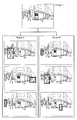
- FIG. 1 is a schematic view of a screen to which the information processing method according to the embodiment can be applied.
- FIG. 2 is a schematic diagram for explaining the difference in the result of object detection by each of the different object detection models.
- FIG. 3A is a diagram schematically showing an object detection result by three object detection models for a common input image.
- FIG. 3B is a diagram showing an example of data of the object detection result set output from the object detection model.
- FIG. 4A is a diagram schematically showing an example of a state after applying the information processing method according to the embodiment to the object detection result shown in FIG. 3A.
- FIG. 4B shows an example of data of the object detection result set after applying the information processing method according to the embodiment.
- FIG. 4A is a diagram schematically showing an example of a state after applying the information processing method according to the embodiment to the object detection result shown in FIG. 3A.
- FIG. 4B shows an example of data of the object detection result set after applying the information processing method according to the embodiment.
- FIG. 5A is a diagram for explaining the result of the processing of inserting alternative data performed in the information processing method according to the embodiment.
- FIG. 5B is a diagram showing an example of data of the object detection result set corresponding to the result of the processing shown in FIG. 5A.
- FIG. 6 is a diagram for explaining a mode different from the example shown in FIG. 5A in the insertion of alternative data performed by the information processing method according to the embodiment.
- FIG. 7A shows a display example on the UI screen to which the information processing method according to the embodiment is applied.
- FIG. 7B shows a display example on the UI screen to which the information processing method according to the embodiment is applied.
- FIG. 7C shows a display example on the UI screen to which the information processing method according to the embodiment is applied.
- FIG. 7D shows a display example on the UI screen to which the information processing method according to the embodiment is applied.
- FIG. 8 is a block diagram showing a configuration example of a computer that executes the information processing method according to the embodiment.
- FIG. 9A is a schematic diagram for explaining the analysis frame acquired by the above information processing method.
- FIG. 9B shows an example of the data of the object detection result set to which the data related to the analysis frame is added.
- FIG. 10 is a flow chart showing the procedure of the information processing method according to the present embodiment.
- the number of detected subjects may be different.
- the creator of the inference model tries to compare and analyze the detection results for each inference model between the inference models, the result for the same inference model is searched from the detection results output by each inference model. It is troublesome, inconvenient and inefficient.
- the estimated position or the range of the image to be detected may differ between the inference models, and the visual association may be troublesome or mistaken. Easy and inefficient.
- the information processing method which was devised in view of the problem of such inefficiency, is a method executed by a computer for the same input data by a plurality of inference devices.
- a plurality of inference results that are the results of inference are acquired, the influence of the input data on each of the plurality of inference results is acquired for each of the plurality of inference results, and the plurality of inference results are obtained based on the plurality of inference results.
- One or more combinations of the inference results of the above are determined, and among the plurality of inference results, the influences acquired for each of the inference results included in the same combination are presented in parallel or superimposed via the presenting device. It is an information processing method to be performed.
- inference results for a common object are selected and combined from the inference results of each of a plurality of inference models (inference devices). Then, the influence of the input data on the inference result included in this combination is presented in parallel or superimposed at one time. Therefore, the behavior (that is, the influence) of each of the plurality of different inferiors can be evaluated in parallel. As a result, the user's time and effort required to analyze the inference result is reduced as compared with the conventional case. Therefore, the user can analyze the inference result more efficiently than in the past.
- each of the plurality of inference devices is an object detector
- each of the plurality of inference results is an object detection result set including a plurality of object detection results
- each of the plurality of inference results is acquired.
- the influence is the influence of the input data on each of the plurality of object detection results included in the object detection result set, and each of the one or more combinations is different from each other among the plurality of the object detection result sets.
- the effects presented in parallel or superimposed on the plurality of object detection results included in the object detection result set are acquired for each of the plurality of object detection results included in the same combination. It may be an effect.
- the influence of the input data on the object detection result included in this combination is displayed in parallel or superimposed at one time.
- the user's labor required to analyze the object detection result is reduced as compared with the conventional case, so that the user can analyze the object detection result more efficiently than in the conventional case.
- Object detection is particularly meaningful because the time and effort required for analysis is enormous because a plurality of objects are detected by each object detector.
- each of the plurality of object detection results includes a class based on the detected object, and even if the class included in each of the plurality of object detection results included in each of the one or more combinations is common. Good.
- each of the plurality of object detection results includes a detection frame
- the one or more combinations include the detection frame included in the plurality of object detection results included in the plurality of object detection result sets different from each other. It may be determined based on the overlap or positional relationship between the two.
- each of the plurality of object detection results includes the likelihood of detection
- the combination of the one or more is the detection included in the plurality of object detection results included in the plurality of object detection result sets different from each other. It may be determined based on the closeness of the likelihoods of each other.
- the same combination when the same combination does not include the plurality of object detection results included in the object detection result set by any of the plurality of object detectors, the same combination is included in the same combination.
- the influence acquired for each of the plurality of object detection results and the alternative data may be presented in parallel.
- the influence and alternative data acquired on the isolated object detection result when there is an isolated object detection result that is not included in any of the one or more combinations among the plurality of object detection results, the influence and alternative data acquired on the isolated object detection result. And may be presented in parallel.
- the user can easily grasp which object detector did not detect which object detector or only which object detector detected. can do.
- the presentation of the influence it was acquired for the reference object detection result which is one of the plurality of object detection results included in the reference object detection result set which is one of the plurality of object detection result sets.
- the influence and the influence obtained for each of the plurality of object detection results included in the combination including the reference object detection result may be presented. Further, the operation of selecting the reference object detection result set may be accepted, and the reference object detection result set may be switched to the object detection result set selected by the operation.
- the user can focus on a specific object detector and analyze the object detection result more efficiently than before.
- analysis by changing the object detector of interest can be performed more efficiently than in the past.
- the operation of selecting the input data is accepted, the input data is switched to the input data selected by the operation, and in the presentation of the influence, each of the plurality of inferiors with respect to the selected input data.
- the obtained influence may be presented for each of the plurality of inference results.
- the user can analyze the object detection result of each object detector more efficiently than before.
- the operation of selecting the group of the object detection results is accepted, and the object detection result or the presented object detection result for the presented influence is switched to the object detection result of the group selected by the operation. You may.
- the user can select the object detection result related to the presentation on the UI screen according to the attribute, and the object detection result can be analyzed more efficiently than in the past.
- information indicating the inference device that outputs the inference result for each of the presented influences may be presented among the plurality of inference devices.
- the information processing method is a method executed by a computer, and includes a plurality of object detection result sets including a plurality of object detection results for the same input data by each of the plurality of object detectors.
- One or more combinations of one or more of the plurality of object detection results included in each of the plurality of object detection result sets are determined based on the plurality of object detection results included in the plurality of object detection result sets. Then, among the plurality of object detection results included in each of the plurality of object detection result sets, the object detection results included in the same combination may be presented in parallel or in superposition via the presenting device.
- the information processing system includes an inference result acquisition unit that acquires a plurality of inference results that are the results of inference for the same input data by each of the plurality of inference devices, and the inference result acquisition unit for each of the plurality of inference results.
- An input data influence acquisition unit that acquires the influence of the input data for each of the plurality of inference results, and a determination unit that determines one or more combinations of the plurality of inference results based on the plurality of inference results.
- An influence presenting unit is provided, which presents the influences acquired for each of the inference results included in the same combination among the plurality of inference results in parallel or in an overlapping manner via a presenting device.
- inference results for a common object are selected and combined from the inference results of each of a plurality of inference models (inference devices). Then, the influence of the input data on the inference result included in this combination is presented in parallel or superimposed at one time. Therefore, the behavior of each of the plurality of different inferiors can be evaluated in parallel. As a result, the user's time and effort required to analyze the inference result is reduced as compared with the conventional case. Therefore, the user can analyze the inference result more efficiently than in the past.
- these comprehensive or specific aspects may be realized by a device, an integrated circuit, or a recording medium such as a computer-readable CD-ROM, and the device, system. , Integrated circuits, methods, computer programs and any combination of recording media.
- FIG. 1 is a schematic view of a screen to which the information processing method according to the embodiment can be applied.
- This screen functions as a user interface of application software used for analyzing the result of inference by an inference device (hereinafter, the user interface, which is written in English, is abbreviated as UI).
- the application software may be a web application that displays this screen (hereinafter referred to as a UI screen) on a web browser, or may be a native application or a hybrid application.
- This application software is executed by a processor provided in various business or personal computers such as a tower type, a desktop type, and a tablet type, and displays such a UI screen on a monitor used by a user.
- the UI screen 10 accepts a user's operation and displays the result of inference by the inference device or information related to the result according to the user's operation.
- the inference device is an object detector that detects an object appearing in the input image indicated by the input data
- the information related to the inference result in this example is, for example, whether or not each part of the input data has an influence on the inference result by the object detector, and if there is an influence, its magnitude and direction (positive influence). Information about either or both).
- the effect is, for example, the reaction of the inference device to the input data in the inference process for outputting the inference result.
- the effect may be expressed as an analysis result (that is, an analysis frame or an analysis value) of the reaction.
- the UI screen 10 is divided into three parts, an input data field, a model field, and a result field, in order from the left.
- the frame individual switching unit 50C is included.
- the input data selection unit 20A presents a candidate of input data for displaying the inference result or the analysis result (hereinafter, also referred to as the result information without distinguishing the inference result and the analysis result) in the result column, and presents the user. Let me choose.
- the input data in this example is image data, and the input data is presented as a thumbnail of the image. Images selected by the user, thumbnails of all images in the example shown in FIG. 1, are surrounded by a thick frame.
- the input data is also referred to as an input image.
- the model selection unit 20B presents a candidate for an inferior to display the result information and causes the user to select it.
- the inference device here is an inference model for machine learning (hereinafter, also simply referred to as a model for convenience).
- the user narrows down the candidate inference models to those used for object detection, and then selects two of "Model A" and "Model E".
- the plurality of models selected by the model selection unit 20B have the same purpose, they are different in terms of training method or network configuration, data set used for training, or training amount. Different from each other.
- the display result selection unit 20C allows the user to select an item of result information to be displayed.
- object detection it is, for example, the type (class) of the detected object that is selected by the user as an item of result information.
- the type (class) of the detected object In the example shown in FIG. 1, cars, bicycles, pedestrians and motorcycles are presented as selectable classes, and pedestrians are selected.
- the user is made to select the result type (TP: True Positive, FP: False Positive, FN: False Negative) as another item of the result information to be displayed.
- TP and FN are selected.
- the model selection unit 20B and the display result selection unit 20C clicks or taps the display button under the display result selection unit 20C, the result information corresponds to the content of the selection. Is displayed on the result display unit 40 in the result column.
- the input image selected by the input data selection unit 20A and the information about the object detection result which is the inference result for the input image are the objects for which the object detection result is output. Displayed with the name of the model for detection.
- the influences of the two models (Model A and Model E) selected by the model selection unit 20B on the inference result on the input image selected by the input data selection unit 20A are superimposed.
- the displayed images are displayed side by side on the result display unit 40.
- the displayed images may be displayed side by side.
- the display data switching unit 50A is a slider, and the input image displayed on the result display unit 40 is switched according to the position of the knob moved by the user. Along with the switching of the input image, the result information superimposed on the input image is also switched. Further, in this example, the name of the input image currently displayed on the result display unit 40 and the order in the selected input image are displayed on the display data switching unit 50A.
- the analysis frame batch switching unit 50B and the analysis frame individual switching unit 50C switch the analysis frame, which is an aspect of the influence on the inference result, which is superimposed on the input image and displayed as a part of the display image in the result display unit 40. Let me do it.
- the switched analysis frame is superimposed on the input image to generate a display image. For example, when each model executes object detection on one input image and a plurality of objects are detected, one analysis frame is generated for each of the plurality of detection results (that is, detection frames). However, what is temporarily superimposed on each input image in the result display unit 40 is one of the plurality of analysis frames generated for the plurality of detection frames. In the example of FIG.
- pressing among the analysis frames generated for the detection results of each of the plurality of models, the analysis frames superimposed on the input image displayed on the result display unit 40 are collectively advanced. It switches with.
- the analysis frame individual switching unit 50C which is a slider, is provided for each input image, that is, the display image on which the analysis frame related to each model is superimposed on the result display unit 40. When the user moves the knob of the slider, the analysis frame superimposed on the input image can be individually switched for each image.
- the information processing method according to the present embodiment By applying the information processing method according to the present embodiment to the UI screen 10, it is possible to analyze the inference result more efficiently using the UI screen 10. In other words, the user can analyze the inference result more efficiently by using the UI screen that can be operated in the same way as before.
- FIG. 2 is a schematic diagram for explaining the difference in the object detection result between such models.
- FIG. 2 shows a detection frame surrounding a pedestrian or a vehicle as a detected object among the object detection results in the input image Image 1 by each of the two models Model A and Model B. Comparing the two object detection results, the number of detected pedestrians is different, and although the size and range of what seems to be a common pedestrian detection frame are similar, they do not match.
- the third detection frame from the top by Model B surrounds a road cone on the road that is erroneously detected as a pedestrian or a car, and is an example of a result type FP. And the car shown at the right end of the image detected in Model A is not detected in Model B. Further, these detection frames are arranged from the top in the order included in the detection result data output from each model, but the order may differ between the models as shown in FIG.
- the user uses the UI screen 10 to compare and analyze the object detection results output by the plurality of models for each object to be detected. At that time, there may be a request to display the results of the common detected objects side by side on the UI screen 10 at one time.
- the user uses the analysis frame individual switching unit 50C to output a common object to be detected, for example, an object that is considered to be the result of detection of a pedestrian appearing near the left end of the image by each model.
- the result display unit 40 displays what is found from the detection results.
- the analysis frame batch switching unit 50B is used after the object detection results output by each model are rearranged and arranged in a desired order by the user.
- the information processing method according to the present embodiment saves the user's trouble in this sorting, so to speak.
- the details of sorting by this method will be described with reference to an example.
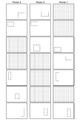
- FIG. 3A is a diagram schematically showing the object detection results by the three object detection models for a common input image.
- the solid rectangle represents the entire area of the input image that is the target of the object detection process.
- the broken line frame and the alternate long and short dash line frame in the solid line rectangle are the detection frames acquired as a result of the object detection process by each model, and the difference in line type is different, for example, pedestrian and car.
- the vertical arrangement of these detection frames corresponds to the order in which the data related to the detection frames are arranged in the object detection result data output by each object detection model.
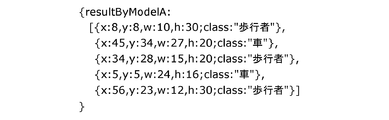
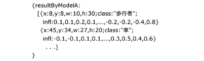
- FIG. 3B shows an example of the object detection result data output from the model Model A.
- Each line from the second line to the sixth line of this data includes an output value related to the detection frame.
- the content of this output value shows the position and size (range) of each detection frame included in the object detection result by Model A in FIG. 3A in the entire image area and the class of the detected object.
- Similar data is output from Model B and C, which are other object detection models.
- a plurality of object detection results output by each object detection model are collectively referred to, and hereinafter also referred to as an object detection result set. That is, the data illustrated in FIG. 3B is the data of the object detection result set consisting of five detection frames acquired as a result of Model A executing object detection on one input image.
- FIG. 3B is the data of the object detection result set consisting of five detection frames acquired as a result of Model A executing object detection on one input image.
- FIG. 3B is the data of the object detection result set consisting of five detection frames acquired as a result of Model A executing object detection on one input image.
- FIG. 3B is the
- FIGS. 4B, 5B and 9B show an example of the structure and numerical values of such data, and the data format and numerical values of the object detection result set are not limited to this example. Further, the items included in each object detection result are not limited to this example. For example, the type of the result described above may be included in the object detection result. The same applies to FIGS. 4B, 5B and 9B used in the following description.
- the result display unit 40 is included in the display image by the operation of the analysis frame batch switching unit 50B and the analysis frame individual switching unit 50C.
- the object detection result (detection frame) is switched in the order in which they are arranged vertically in the figure.
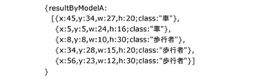
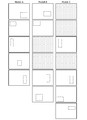
- FIG. 4A is a diagram schematically showing an example of a state after applying the information processing method according to the present embodiment to the object detection result shown in FIG. 3A.
- the detection frames that are the object detection results by each object detection model are sorted according to the class of the object to be detected. This is because the output value of each detection frame in the data of the object detection result set output by each object detection model by this information processing method depends on the class of the object to be detected ("car", "pedestrian"). Reflects that it has been sorted.
- the output value of each detection frame in the second to sixth rows is the class of the object to be detected ("". It is sorted in the order of "car", "pedestrian”). The same sorting is performed on the data of the object detection result set output from Models B and C.
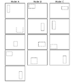
- FIG. 5A is a diagram for explaining the result of processing performed following the above-mentioned sorting performed according to the class of the detected object in the information processing method according to the present embodiment. The results shown in FIG. 5A will be described focusing on the differences from the states shown in FIG. 4A.
- FIG. 5A it is a detection result for a common object to be detected (or a detection result for a common object to be detected) among the object detection result sets output by each of the object detection models of Models A, B, and C. (Most likely) are placed in the same position (in order) in the vertical direction.
- the object detection results in the object detection result set output by the other model are displayed based on the order of the object detection results in the object detection result set output by one of the models. Rearranges.
- the model in the detection result set output by the model that is not the reference of the order is The order of the object detection results may be determined.
- the overlap between the detection frames is, for example, IoU (Intersection over Union), that is, the ratio of the intersection to the union of the detection frames. Or, more simply, it may be decided whether or not to place them in the same order based on the size of the overlapping portion between the detection frames of the same class.
- the positional relationship of each detection frame of the same class is set between the object detection result sets output by each of the plurality of object detection models. It may be determined based on. As a specific example based on the positional relationship of the detection frames, the distance between the corresponding vertices or the corresponding sides of the two detection frames, or the distance between the geometric centers of gravity of the two detection frames may be used.
- the detection results for each object to be detected are placed in the same order in the object detection result set output by each of the plurality of object detection models. It is also called determining the combination.
- the two or three object detection results contained in the same row in FIG. 5A are included in the same combination.
- the object detection results included in the same combination are temporarily displayed on the result display unit 40 without the user searching for or rearranging them.
- the detection frames that are the object detection results by the models placed in the same row are the same class of detection frames, and the IoU is larger than the detection frames in the other rows. , Or the position in the image is closer.
- Whether or not to include the detection results of different models based on the overlap between the detection frames such as IoU or the positional relationship of the detection frames in the same combination is determined by, for example, the overlap or the distance and the predetermined threshold value. It may be determined by comparison. Even if the detection results are in the same class and have a larger IoU than the detection frames in other rows, if the IoU is below a predetermined threshold, it is decided not to include them in the same combination. Will be done. Further, as another example, the determination may be made by optimizing the whole by the Hungarian method or the like.
- the object detection result set (hereinafter, also referred to as the reference object detection result set) used by the computer that executes the information processing method according to the present embodiment as a reference for rearranging the object detection results in each object detection result set.
- the selection method is not particularly limited.
- the user may be allowed to select a reference object detection result set.
- the one having the smallest number of detection results (detection frames) included in the object detection result, or the one having the largest number of detection results (detection frame) may be selected as the reference object detection result set. Further, for example, it may be randomly selected at the time of sorting.
- FIG. 5A shows the result of using the order of the object detection results in the object detection results by Model A as a reference in such processing performed in the information processing method according to the present embodiment.
- results shown in FIG. 5A include rectangles with halftone dots that are not shown in FIG. 4A. This is inserted into the object detection result set by the model that did not detect the detected object when there is a detected object detected by only a part of the models selected by the model selection unit 20B.
- Data indicating alternative information (hereinafter referred to as alternative data) is shown.
- FIG. 5B is a diagram showing an example of inserting alternative information into the object detection result set output by Model A. It is an example of the alternative information in which " ⁇ blanc ⁇ " of the 4th line and the 5th line in FIG. 5B is inserted. This information corresponds to the two dots with halftone dots found in the column of object detection results by Model A in FIG. 5A.
- the alternative data is presented in parallel with the display image based on the object detection result by another model in the result display unit 40, so that the user is provided with the information that the detected object was not detected in the model.
- Such alternative data may be presented in the result display unit 40 as, for example, a blank frame or a simple blank area without a frame, or presented as characters, symbols, patterns or figures indicating that the data has not been detected. May be done.
- FIG. 6 is a diagram for explaining a mode different from the example of FIG. 5A for inserting alternative data.
- the order of the object detection results in the object detection result set by Model A was used as the reference for the order of the object detection results.
- alternative data is not inserted into the object detection result set of Model A, and the sorted state based on the class shown in FIG. 4A is maintained.
- the detection results of the objects to be detected that are not detected by Model A are collected at the end (bottom) of the order.
- Sorting of object detection results in such an object detection result set may be automatically executed, for example, when the user presses the display button.
- the UI screen 10 may include an operation component (not shown) that receives an instruction to execute such a rearrangement from the user, and the rearrangement may be executed in response to an operation on the operation component.
- the fourth and sixth from the top of Model A, and in FIG. 6, the fourth from the top of Model A are the detected objects that were detected in only one of the three models.
- Corresponds to the detection result of (hereinafter referred to as the isolated object detection result).
- the isolated object detection result is not included in any of the combinations of the object detection results determined as described above.
- a display image based on such an isolated object detection result may also be presented in parallel with the alternative data in the result display unit 40.
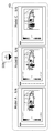
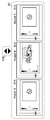
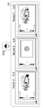
- FIGS. 7A to 7D show an example of display on the UI screen 10 after such rearrangement is performed.
- 7A to 7D show an excerpt of a part of the result display unit 40 and the analysis frame batch switching unit 50B in the result column of the UI screen 10.
- For the image to be detected by the object refer to the image Image 1 in FIG.
- the display images including the analysis results of the detection results of the pedestrians reflected slightly to the left from the center, which were detected in all three models, are shown in parallel.
- the analysis result magnitude and directionality of influence
- the analysis frame is schematically represented by a patterned region superimposed on the image. The part where the analysis frame is not superimposed indicates that the part of the input image did not affect the object detection result or the influence was very small.
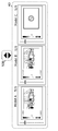
- FIG. 7B shows the state of the result display unit 40 after the downward-pointing triangle included in the analysis frame batch switching unit 50B is pressed once in the state shown in FIG. 7A.
- a display image including the analysis result of the detection result of the pedestrian near the left end of the input image is shown.
- Model C since this pedestrian was not detected, a frame including a figure as alternative data is displayed side by side with other display images.
- FIG. 7C shows the state of the result display unit 40 after the downward-pointing triangle included in the analysis frame batch switching unit 50B is pressed once more in the state shown in FIG. 7B.
- the display image including the analysis result of the pedestrian detection result included only in the object detection result set output by Model B and the frame including the figure as alternative data for Model A and Model C are parallel. It is shown in.
- FIG. 7D shows the state of the result display unit 40 after the downward-pointing triangle included in the analysis frame batch switching unit 50B is pressed once more in the state shown in FIG. 7C.
- two display images including the analysis result of the vehicle detection result commonly included in the object detection result set by Model A and the object detection result set by Model C, and Model B as alternative data.
- the frame containing the figure is shown in parallel.
- the combinations determined in this way in the object detection process by each model, the influence of the input image on the object detection results included in the same combination is presented to the user in parallel. As a result, the user can simultaneously view the detection results for the same detected object for analysis without having to search for the detection results for the same detected object or rearrange the searched detection results. Can be done.
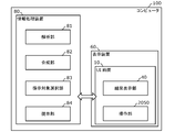
- FIG. 8 is a block diagram showing a configuration example of a computer 100 on which the information processing method according to the present embodiment is executed.
- the computer 100 is the various computers described above, and includes an information processing device 80 and a display device 60.
- the information processing device 80 includes a storage unit that stores the above-mentioned application software and an arithmetic processing unit that reads and executes the application software.
- the information processing device 80 includes an analysis unit 81, a synthesis unit 82, a presentation target selection unit 83, and a presentation unit 84 as functional components provided by executing the application software.
- the analysis unit 81 has each of the images (hereinafter referred to as input images) to be object detection processed for each of the plurality of object detection results (that is, each detection frame) included in the object detection result set output by the object detection model. Calculate the presence or absence of influence by the part (size and directionality if any). Such effects are calculated using various methods. For example, the impact can be calculated using the methods disclosed in the following documents.
- the analysis unit 81 is an example of the inference result acquisition unit and the input data influence acquisition unit in the present embodiment.
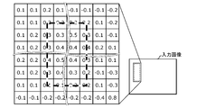
- FIG. 9A is a schematic diagram for explaining the calculation of the influence by the analysis unit 81.
- the broken line frame in the input image represents the detection frame which is the object detection result.
- the left side of the input image is an excerpt of the area including the detection frame, and the squares are the pixels (partially omitted) that make up the input image.
- the numerical value in the grid is a value calculated by the analysis unit 81 and representing the influence of the value of each pixel on the object detection result (hereinafter, also referred to as an analysis value).
- an analysis value is input to each pixel for convenience of explanation, but such data is not added to the value possessed by each pixel. Further, in the above description, the analysis value is described as being calculated for each pixel, but the analysis value is not limited to this. After grouping a plurality of pixels into super pixels, the analysis value may be calculated for each super pixel.
- the range of pixels from which the analysis value is calculated differs depending on the design value of the object detection model and the size of the detection frame.
- the analysis value is calculated for a range in which the pixels overlapping the detection frame are expanded by 2 pixels vertically and 4 pixels horizontally.
- the above-mentioned analysis frame corresponds to the outline of the entire set of pixels for which the influence is calculated in this way, or the contour of the set of pixels whose magnitude of the calculated influence is within a specific range.
- FIG. 9B is a diagram showing an example of data of the object detection result set in which the analysis value calculated by the analysis unit 81 is added to the object detection result.
- the data of the analysis value calculated by the analysis unit 81 as shown in FIG. 9A is inserted into the data of the object detection result set output by Model A also shown in FIG. 3B.
- the second line is data showing the position and size of the detection frame and the class of the object to be detected to which the detection frame is attached
- the third line is the analysis unit 81 for this detection frame. Is the data of the analysis value calculated by (omitted in the middle). From the fourth line onward, the position and size of other detection frames included in the data of this object detection result set, the class of the object to be detected, and the data of the analysis value calculated for this detection frame follow.
- the synthesis unit 82 synthesizes and outputs an image in which an analysis frame is superimposed on an input image, that is, a display image, based on the analysis value calculated by the analysis unit 81.
- this analysis frame is represented by a patterned region as illustrated in FIGS. 1 and 7A to 7D.
- one display image is combined for each detection frame. Such a display image is the influence of one input image and the input image on the object detection result executed on the input image, and the analysis result calculated by the analysis unit 81 is collectively shown.
- the presentation target selection unit 83 selects a display image to be displayed on the result display unit 40 via the presentation unit 84 in response to an input from the operation unit 2050 included in the UI screen 10 displayed on the display device 60 such as a monitor. To do.
- the operation unit 2050 is a component on the UI screen 10 that accepts an operation in which the user selects a group of object detection results for which the analysis result is included in the display image displayed on the result display unit 40. This group is defined by the attributes of the object detection result such as the class of the object to be detected and the result type.
- the operation unit 2050 in the present embodiment includes an input data selection unit 20A, a model selection unit 20B, a display result selection unit 20C, a display data switching unit 50A, an analysis frame batch switching unit 50B, and an analysis frame individual switching unit 50C. ..
- the input from the operation unit 2050 includes information on the input image and model selected by the user, and information on the group of object detection results, that is, information on the class or result type of the object to be detected.
- the presentation target selection unit 83 selects the display image output by the synthesis unit 82 to be displayed on the result display unit 40. Further, the presentation target selection unit 83 rearranges the selected display images in each object detection result set to determine the combination. Furthermore, alternative information is inserted into the object detection result set, which lacks the detection result for the object to be detected in common with other models, depending on the setting or specification.
- the presentation target selection unit 83 is an example of the determination unit in the present embodiment.
- the presentation unit 84 outputs to the display device 60 so that the display images included in the same combination among the combinations determined by the presentation target selection unit 83 are displayed in parallel on the result display unit 40.
- alternative data is output so as to be displayed on the result display unit 40 in parallel with the display image according to the setting or the specification.
- the result display unit 40 of the presentation unit 84 and the display device 60 is an example of the influence presentation unit in the present embodiment. Further, the display device 60 is an example of the presentation device in the present embodiment.
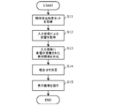
- the flow chart shown in FIG. 10 shows the procedure of the information processing method according to the present embodiment executed by the computer 100 having such a configuration.
- the processing by each of the above functional components will be described below as a processing by the computer 100.
- the computer 100 acquires an object detection result set output by executing object detection on a common input image by a plurality of different object detection models (step S11).
- This object detection result set includes output values for individual detection frames that are object detection results (see FIG. 3B).
- it may be the computer 100 or a device other than the computer 100 that actually acquires the data of the input image and executes the object detection by the object detection model on the data.
- an information processing terminal such as a smartphone or an information processing device provided in a device such as a camera may execute object detection on an image captured by an image sensor included in each device.
- the computer 100 calculates the influence of each part of the input image on the calculation of the output value related to the detection frame for each detection frame which is the object detection result included in each object detection result set (step S12). ..
- the calculation of the effect is specifically to calculate an analysis value indicating either or both of the magnitude (including the presence or absence) and the direction of the effect.
- the computer 100 synthesizes a display image in which the influence calculated in step S12 is superimposed on the input image (step S13). Specifically, based on the calculated analysis value, a display image in which an analysis frame is superimposed on the input image is synthesized.
- the computer 100 determines the combination of the detection results (detection frames) included in the object detection result sets output by different object detection models (step S14).
- the detection results included in the same combination may be the detection results for a common detected object or the detection results for a common detected object based on the overlap or positional relationship between the detection frames. It is judged that the sex is higher than the predetermined standard.
- the process of determining this combination may also include inserting alternative information into the object detection result set, depending on the settings or specifications.
- the computer 100 presents a display image selected according to the setting of the object detection result group defined by the attributes such as class and result type (step S15). Since this selection is performed in the unit of the combination determined in step S14, the display images including the analysis results of the detection results of the common detected bodies (or the detected bodies that are likely to be common) are presented in parallel. Will be done.
- the composition of the analysis image (S13), the acquisition of the influence (S12), and the composition of the analysis image (S13) may be executed after the combination is determined (S14) and before the display image is actually presented. ..
- the input image to be included in the display image to be displayed on the result display unit 40 is first selected based on the object detection result. Then, the acquisition of the influence and the synthesis of the analysis image may be synthesized only for the object detection result for the selected input image.
- step S15 the user's operation regarding the group setting on the UI screen 10 is accepted at any stage before step S15, and the display target according to this setting becomes the processing target in the unexecuted procedure. May be good.
- the result display unit 40 switches to the display image based on the object detection result selected according to the latest group setting.
- the displayed image may be displayed once without executing the combination determination (step S14).
- step S14 may be executed, and the display content on the result display unit 40 may be updated according to the result.
- the display content reflecting the result of step S14 and the display content not reflecting the result may be reversibly switchable.
- the calculation of the influence is executed by the computer 100, but the calculation is not limited to this.
- the calculation of the influence may be executed by a device other than the computer 100 provided with the information processing device, and the computer 100 may directly or indirectly receive and acquire the input of the influence output from this device.
- the expression mode of the influence is exemplified only by the frame (analysis frame) along the region or its outline, but is not limited to this.
- the frame analysis frame
- it may be represented by a figure such as a point or a cross placed at the center of an area or a geometric center of gravity.
- a plurality of object recognition results included in the same combination and individually acquired effects on these object recognition results are superimposed.
- a plurality of display images are presented in parallel on the left and right lines on the result display unit 40, but the form of presentation is not limited to this. For example, they may be presented in parallel in one upper and lower column, or may be arranged and presented on a matrix consisting of a plurality of rows and a plurality of columns such as a rice field shape.
- the detection frame which is the object detection result by each of the plurality of models, or the analysis frame acquired for the detection frame may be superimposed on one input image collectively.
- the analysis frame in this case may be shown only by the outline or by a region painted with higher transparency, instead of the region with the pattern as illustrated in FIGS. 7A to 7D.
- the result display unit 40 may present an input image on which a detection frame, which is an object detection result, is superimposed, instead of or in addition to the influence. Further, the information superimposed on the input image may be switchable according to the operation of the user.
- the object detection result included in one combination and the object are temporarily displayed on the UI screen 10 on the result display unit 40. It was only the effect obtained on the detection result, but it is not limited to this.
- the result display unit 40 supports a plurality of combinations as long as the display images based on the object detection results included in the same combination can be easily grasped by the user by collecting and arranging them or enclosing them in a frame.
- the display image may be presented at one time.
- the combination is determined by rearranging the contents of the data of the object detection result set and placing them in the same order, but the realization form of the combination is not limited to this.
- an identifier indicating the combination to which each object detection result belongs can be added, or a table that holds the combination information separately from the object detection result set is generated or updated. You may do it.
- a combination that determines the display image to be presented by the result display unit 40 may be determined by being calculated each time according to the operation of the user.
- Sorting according to the class of the detected object described with reference to FIGS. 3A and 4A is not only for comparing inference results between a plurality of models, but also for organizing the inference results by one model. It may be executed.
- sorting according to the class is not essential. That is, the combination may be determined based on the overlap or positional relationship between the detection frames without sorting according to the class.
- the determination of the combination of the object detection results is executed based on the overlap or the positional relationship between the detection frames, but the determination of the combination is performed.
- the method is not limited to this.
- the combination may be determined based on the similarity between the influences.
- the degree of similarity of the influence is, for example, the size of the vector whose element is the size of the pixel area (vertical x horizontal) in which the analysis unit 81 calculates the analysis value for the object detection result output by each of the two object detection models. It can be determined based on comparison or similarity between these vectors (eg, cosine distance).
- the combination of the object detection results may be determined based on the overlap or position of the detection frames and the closeness of the likelihood of the detection results. For example, a score may be given so as to give a higher score to those having a larger overlap of detection frames and those having a closer likelihood of detection results, and the combination may be determined based on the scoring results.
- a part or all of the functional components included in each of the above-mentioned information processing systems may be composed of one system LSI (Large Scale Integration).
- a system LSI is an ultra-multifunctional LSI manufactured by integrating a plurality of components on a single chip. Specifically, a microprocessor, a ROM (Read-Only Memory), and a RAM (Random Access Memory) are used. It is a computer system that includes such as. A computer program is stored in the ROM. When the microprocessor operates according to this computer program, the system LSI achieves the function of each component.
- system LSI Although it is referred to as a system LSI here, it may be referred to as an IC, an LSI, a super LSI, or an ultra LSI due to the difference in the degree of integration. Further, the method of making an integrated circuit is not limited to LSI, and may be realized by a dedicated circuit or a general-purpose processor. An FPGA (Field Programmable Gate Array) that can be programmed after the LSI is manufactured, or a reconfigurable processor that can reconfigure the connection and settings of the circuit cells inside the LSI may be used.
- FPGA Field Programmable Gate Array
- One aspect of the present disclosure is not limited to the information processing method described above using the flow chart of FIG. 10, and may be a program executed by the computer 100 and an information processing system including the computer 100. Also, one aspect of the present disclosure may be a computer-readable, non-temporary recording medium on which such a computer program is recorded.
- the information processing method and the like according to the present disclosure can be used as a user interface used for comparing the results of inference processing by a computer.
Landscapes
- Engineering & Computer Science (AREA)
- Theoretical Computer Science (AREA)
- Physics & Mathematics (AREA)
- General Physics & Mathematics (AREA)
- Computer Vision & Pattern Recognition (AREA)
- Multimedia (AREA)
- Software Systems (AREA)
- Health & Medical Sciences (AREA)
- Artificial Intelligence (AREA)
- Computing Systems (AREA)
- Databases & Information Systems (AREA)
- Evolutionary Computation (AREA)
- General Health & Medical Sciences (AREA)
- Medical Informatics (AREA)
- Image Analysis (AREA)
- Closed-Circuit Television Systems (AREA)
- User Interface Of Digital Computer (AREA)
Abstract
Description
発明者らは、上述した提案されている従来の技術では、以下の問題が生じることを見出した。
図1は、実施の形態に係る情報処理方法が適用可能な画面の模式図である。この画面は、推論器による推論の結果の解析に用いられるアプリケーションソフトウェアのユーザインタフェース(以下、英文表記であるUser Interfaceを略してUIと表記する)として機能する。このアプリケーションソフトウェアは、この画面(以下、UI画面と呼ぶ)をウェブブラウザで表示させるウェブアプリケーションであってもよいし、ネイティブアプリケーション又はハイブリッドアプリケーションであってもよい。このアプリケーションソフトウェアは、例えばタワー型、デスクトップ型、タブレット型等の各種の業務用又は個人用のコンピュータが備えるプロセッサによって実行されて、ユーザが使用するモニタにこのようなUI画面を表示させる。
本開示の一又は複数の態様に係る情報処理方法は、上記の実施の形態の説明に限定されるものではない。本開示の趣旨を逸脱しない限り、当業者が想到する各種の変形を上記の実施の形態に施したものも、本開示の態様に含まれてもよい。下記にそのような変形の例、及び実施の形態の説明へのその他の補足事項を挙げる。
20A 入力データ選択部
20B モデル選択部
20C 表示結果選択部
40 結果表示部
50A 表示データ切替部
50B 解析枠一括切替部
50C 解析枠個別切替部
60 表示装置
80 情報処理装置
81 解析部
82 合成部
83 提示対象選択部
84 提示部
100 コンピュータ
2050 操作部
Claims (15)
- コンピュータにより実行される方法であって、
複数の推論器それぞれによる同じ入力データに対する推論の結果である複数の推論結果を取得し、
前記複数の推論結果それぞれに前記入力データが及ぼした影響を、前記複数の推論結果のそれぞれについて取得し、
前記複数の推論結果に基づいて前記複数の推論結果同士の組合せを1つ以上決定し、
前記複数の推論結果のうち、同一の前記組合せに含まれる推論結果それぞれについて取得した前記影響同士を並列に又は重畳して提示装置を介して提示する
情報処理方法。 - 前記複数の推論器のそれぞれは、物体検出器であり、
前記複数の推論結果のそれぞれは、複数の物体検出結果を含む物体検出結果セットであり、
前記複数の推論結果のそれぞれについて取得する前記影響は、前記物体検出結果セットが含む前記複数の物体検出結果それぞれに前記入力データが及ぼした影響であり、
前記1つ以上の組合せのそれぞれは、複数の前記物体検出結果セットのうち互いに異なる物体検出結果セットに含まれている複数の物体検出結果を含み、
前記並列に又は重畳して提示される影響は、前記同一の組合せに含まれる前記複数の物体検出結果のそれぞれに対して取得された影響である
請求項1に記載の情報処理方法。 - 前記複数の物体検出結果のそれぞれは、検出された物体に基づくクラスを含み、
前記1つ以上の組合せのそれぞれに含まれる前記複数の物体検出結果がそれぞれ含む前記クラスは共通である
請求項2に記載の情報処理方法。 - 前記複数の物体検出結果のそれぞれは、検出枠を含み、
前記1つ以上の組合せは、互いに異なる前記複数の物体検出結果セットに含まれる前記複数の物体検出結果が含む前記検出枠同士の重なり又は位置関係に基づいて決定される
請求項2又は3に記載の情報処理方法。 - 前記複数の物体検出結果のそれぞれは、検出の尤度を含み、
前記1つ以上の組合せは、互いに異なる前記複数の物体検出結果セットに含まれる前記複数の物体検出結果が含む前記検出の尤度同士の近さにさらに基づいて決定される
請求項4に記載の情報処理方法。 - 前記影響の提示では、前記同一の組合せが、複数の前記物体検出器のいずれかによる前記物体検出結果セットに含まれる前記複数の物体検出結果を含まない場合、前記同一の組合せに含まれる前記複数の物体検出結果それぞれに対して取得された前記影響と代替データとを並列に提示する
請求項2~5のいずれか一項に記載の情報処理方法。 - さらに、前記複数の物体検出結果のうち、前記1つ以上の組合せのいずれにも含まれていない孤立物体検出結果がある場合、前記孤立物体検出結果に対して取得された影響と代替データとを並列に提示する
請求項2~6のいずれか一項に記載の情報処理方法。 - 前記影響の提示では、前記複数の物体検出結果セットのうちの1つである基準物体検出結果セットが含む前記複数の物体検出結果の1つである基準物体検出結果に対して取得された影響と、前記基準物体検出結果が含まれる前記組合せに含まれる前記複数の物体検出結果のそれぞれに対して取得された影響と、を提示する
請求項2~7のいずれか一項に記載の情報処理方法。 - さらに、前記基準物体検出結果セットを選択する操作を受け付け、
前記基準物体検出結果セットを、前記操作によって選択された物体検出結果セットに切り替える
請求項8に記載の情報処理方法。 - さらに、前記入力データを選択する操作を受け付け、
前記入力データを、前記操作によって選択された入力データに切り替え、
前記影響の提示では、前記選択された入力データに対する前記複数の推論器のそれぞれによる前記複数の推論結果それぞれに対して取得された影響を提示する
請求項1~9のいずれか一項に記載の情報処理方法。 - さらに、前記物体検出結果のグループを選択する操作を受け付け、
提示される前記影響に対する前記物体検出結果又は提示される前記物体検出結果を、前記操作によって選択されたグループの物体検出結果に切り替える
請求項2~10のいずれか一項に記載の情報処理方法。 - 前記影響の提示では、さらに、前記複数の推論器のうち、提示される前記影響それぞれについての前記推論結果を出力した推論器を示す情報を提示する
請求項1~11のいずれか一項に記載の情報処理方法。 - コンピュータにより実行される方法であって、
複数の物体検出器それぞれによる同じ入力データに対する複数の物体検出結果をそれぞれ含む複数の物体検出結果セットを取得し、
前記複数の物体検出結果セットがそれぞれ含む前記複数の物体検出結果に基づいて、前記複数の物体検出結果セットがそれぞれ含む前記複数の物体検出結果の一つ同士の組合せを一つ以上決定し、
前記複数の物体検出結果セットがそれぞれ含む前記複数の物体検出結果のうち、同一の前記組合せに含まれる物体検出結果を、並列に又は重畳して提示装置を介して提示する
情報処理方法。 - 複数の推論器それぞれによる同じ入力データに対する推論の結果である複数の推論結果を取得する推論結果取得部と、
前記複数の推論結果それぞれに前記入力データが及ぼした影響を、前記複数の推論結果のそれぞれについて取得する入力データ影響取得部と、
前記複数の推論結果に基づいて前記複数の推論結果同士の組合せを1つ以上決定する決定部と、
前記複数の推論結果のうち、同一の前記組合せに含まれる推論結果それぞれについて取得された前記影響同士を並列に又は重畳して提示装置を介して提示する影響提示部と、
を備える情報処理システム。 - プロセッサを備える情報処理装置において、前記プロセッサによって実行されることで前記プロセッサに、
複数の推論器それぞれによる同じ入力データに対する推論の結果である複数の推論結果を取得させ、
前記複数の推論結果それぞれに前記入力データが及ぼした影響を、前記複数の推論結果のそれぞれについて取得させ、
前記複数の推論結果に基づいて前記複数の推論結果同士の組合せを1つ以上決定させ、
前記複数の推論結果のうち、同一の前記組合せに含まれる推論結果それぞれについて取得させた前記影響同士を並列に又は重畳して提示装置を介して提示させる
プログラム。
Priority Applications (4)
| Application Number | Priority Date | Filing Date | Title |
|---|---|---|---|
| EP20896142.5A EP4072129A4 (en) | 2019-12-02 | 2020-09-18 | INFORMATION PROCESSING METHOD, INFORMATION PROCESSING SYSTEM AND PROGRAM |
| CN202080082714.5A CN114788265B (zh) | 2019-12-02 | 2020-09-18 | 信息处理方法、信息处理系统和存储介质 |
| JP2021562462A JP7478960B2 (ja) | 2019-12-02 | 2020-09-18 | 情報処理方法、情報処理システム及びプログラム |
| US17/826,990 US12260624B2 (en) | 2019-12-02 | 2022-05-27 | Information processing method for presenting influences obtained for prediction results, information processing system, and recording medium |
Applications Claiming Priority (2)
| Application Number | Priority Date | Filing Date | Title |
|---|---|---|---|
| JP2019-218153 | 2019-12-02 | ||
| JP2019218153 | 2019-12-02 |
Related Child Applications (1)
| Application Number | Title | Priority Date | Filing Date |
|---|---|---|---|
| US17/826,990 Continuation US12260624B2 (en) | 2019-12-02 | 2022-05-27 | Information processing method for presenting influences obtained for prediction results, information processing system, and recording medium |
Publications (1)
| Publication Number | Publication Date |
|---|---|
| WO2021111704A1 true WO2021111704A1 (ja) | 2021-06-10 |
Family
ID=76221719
Family Applications (1)
| Application Number | Title | Priority Date | Filing Date |
|---|---|---|---|
| PCT/JP2020/035522 Ceased WO2021111704A1 (ja) | 2019-12-02 | 2020-09-18 | 情報処理方法、情報処理システム及びプログラム |
Country Status (5)
| Country | Link |
|---|---|
| US (1) | US12260624B2 (ja) |
| EP (1) | EP4072129A4 (ja) |
| JP (1) | JP7478960B2 (ja) |
| CN (1) | CN114788265B (ja) |
| WO (1) | WO2021111704A1 (ja) |
Cited By (2)
| Publication number | Priority date | Publication date | Assignee | Title |
|---|---|---|---|---|
| JP2023113172A (ja) * | 2022-02-03 | 2023-08-16 | 株式会社デンソーテン | 画像認識装置及び方法並びに学習用データセット生成装置 |
| JP2026509783A (ja) * | 2023-03-08 | 2026-03-25 | 日本電気株式会社 | ビデオストリームを処理するためのハードウェアリソースを割り当てる方法、装置、システムおよびプログラム |
Citations (2)
| Publication number | Priority date | Publication date | Assignee | Title |
|---|---|---|---|---|
| JP2018077829A (ja) * | 2016-11-09 | 2018-05-17 | パナソニックIpマネジメント株式会社 | 情報処理方法、情報処理装置およびプログラム |
| JP2018181273A (ja) | 2017-04-21 | 2018-11-15 | キヤノン株式会社 | 画像処理装置及びその方法、プログラム |
Family Cites Families (11)
| Publication number | Priority date | Publication date | Assignee | Title |
|---|---|---|---|---|
| JP4161769B2 (ja) * | 2003-03-31 | 2008-10-08 | カシオ計算機株式会社 | 画像出力装置、画像出力方法、画像出力処理プログラム、および画像配信サーバ、画像配信処理プログラム |
| JP4949924B2 (ja) * | 2007-05-17 | 2012-06-13 | オリンパス株式会社 | 撮影システム及び撮影装置 |
| AU2011203219B2 (en) * | 2011-06-30 | 2013-08-29 | Canon Kabushiki Kaisha | Mode removal for improved multi-modal background subtraction |
| JP6474107B2 (ja) * | 2013-06-28 | 2019-02-27 | 日本電気株式会社 | 映像監視システム、映像処理装置、映像処理方法および映像処理プログラム |
| EP3118813B1 (en) * | 2014-03-14 | 2021-06-02 | Omron Corporation | Image recognition device, image sensor, and image recognition method |
| CN105892787B (zh) * | 2015-08-03 | 2019-06-25 | 中国电建集团昆明勘测设计研究院有限公司 | 一种多机、多模型与多窗口同步浏览与分析方法 |
| US10269135B2 (en) * | 2017-03-14 | 2019-04-23 | Qualcomm Incorporated | Methods and systems for performing sleeping object detection in video analytics |
| CN107886539B (zh) * | 2017-10-19 | 2021-05-14 | 昆明理工大学 | 一种工业场景下高精度齿轮视觉检测方法 |
| JP2019159553A (ja) * | 2018-03-09 | 2019-09-19 | 株式会社東芝 | 情報処理装置、情報処理方法およびプログラム |
| JP7151787B2 (ja) * | 2018-12-26 | 2022-10-12 | 日本電気株式会社 | 情報処理装置、情報処理方法、およびプログラム |
| CN110008853B (zh) * | 2019-03-15 | 2023-05-30 | 华南理工大学 | 行人检测网络及模型训练方法、检测方法、介质、设备 |
-
2020
- 2020-09-18 EP EP20896142.5A patent/EP4072129A4/en not_active Withdrawn
- 2020-09-18 JP JP2021562462A patent/JP7478960B2/ja active Active
- 2020-09-18 CN CN202080082714.5A patent/CN114788265B/zh active Active
- 2020-09-18 WO PCT/JP2020/035522 patent/WO2021111704A1/ja not_active Ceased
-
2022
- 2022-05-27 US US17/826,990 patent/US12260624B2/en active Active
Patent Citations (2)
| Publication number | Priority date | Publication date | Assignee | Title |
|---|---|---|---|---|
| JP2018077829A (ja) * | 2016-11-09 | 2018-05-17 | パナソニックIpマネジメント株式会社 | 情報処理方法、情報処理装置およびプログラム |
| JP2018181273A (ja) | 2017-04-21 | 2018-11-15 | キヤノン株式会社 | 画像処理装置及びその方法、プログラム |
Non-Patent Citations (5)
| Title |
|---|
| BOCHINSKI, ERIK; EISELEIN VOLKER; SIKORA THOMAS: "High-Speed tracking-by-detection without using image information", 2017 14TH IEEE INTERNATIONAL CONFERENCE ON ADVANCED VIDEO SIGNAL BASED SURVEILLANCE (AVSS, 29 August 2017 (2017-08-29), pages 1 - 6, XP033233368, DOI: 10.1109/AVSS.2017.8078516 * |
| DENIS GUDOVSKIYALEC HODGKINSONTAKUYA YAMAGUCHIYASUNORI ISHIISOTARO TSUKIZAWA: "Explain to Fix: A Framework to Interpret and Correct DNN Object Detector Predictions", ARXIV: 1811.08011V1, 19 November 2018 (2018-11-19) |
| ERIK BOCHINSKI ET AL.: "High-Speed tracking-by-detection without using image information", 14TH IEEE INTERNATIONAL CONFERENCE ON ADVANCED VIDEO AND SIGNAL BASED SURVEILLANCE (AVSS, August 2017 (2017-08-01) |
| KUBOTA,TOMONORI, MURATA, YASUYUKI, UEHARA, YOSHIFUMI, NAKACAWA, AKIRA: "A method for visualizing the cause of misrecognition in object recognition using CNN", IPSJ SIG NOTES, vol. 2019-CVIM-218, no. 20, 28 August 2019 (2019-08-28), pages 1 - 6, XP009536087 * |
| See also references of EP4072129A4 |
Cited By (4)
| Publication number | Priority date | Publication date | Assignee | Title |
|---|---|---|---|---|
| JP2023113172A (ja) * | 2022-02-03 | 2023-08-16 | 株式会社デンソーテン | 画像認識装置及び方法並びに学習用データセット生成装置 |
| JP7826032B2 (ja) | 2022-02-03 | 2026-03-09 | 株式会社デンソーテン | 画像認識装置及び方法並びに学習用データセット生成装置 |
| JP2026509783A (ja) * | 2023-03-08 | 2026-03-25 | 日本電気株式会社 | ビデオストリームを処理するためのハードウェアリソースを割り当てる方法、装置、システムおよびプログラム |
| JP7889750B2 (ja) | 2023-03-08 | 2026-07-14 | 日本電気株式会社 | ビデオストリームを処理するためのハードウェアリソースを割り当てる方法、装置、システムおよびプログラム |
Also Published As
| Publication number | Publication date |
|---|---|
| CN114788265B (zh) | 2026-05-08 |
| JP7478960B2 (ja) | 2024-05-08 |
| EP4072129A4 (en) | 2023-05-03 |
| US20220292816A1 (en) | 2022-09-15 |
| US12260624B2 (en) | 2025-03-25 |
| CN114788265A (zh) | 2022-07-22 |
| JPWO2021111704A1 (ja) | 2021-06-10 |
| EP4072129A1 (en) | 2022-10-12 |
Similar Documents
| Publication | Publication Date | Title |
|---|---|---|
| US12229643B2 (en) | Teaching data extending device, teaching data extending method, and program | |
| JP2015143951A (ja) | 物体判別装置、画像センサ、物体判別方法 | |
| US7931602B2 (en) | Gaze guidance degree calculation system, gaze guidance degree calculation program, storage medium, and gaze guidance degree calculation method | |
| KR20230073875A (ko) | 이미지를 적응적으로 디스플레이하는 전자 장치 및 그 동작 방법 | |
| CN113283513A (zh) | 基于目标互换和度量学习的小样本目标检测方法及系统 | |
| CN114510142B (zh) | 基于二维图像的手势识别方法及其系统和电子设备 | |
| CN108520263B (zh) | 一种全景图像的识别方法、系统及计算机存储介质 | |
| JP2020042684A (ja) | 検索装置、検索方法及びプログラム | |
| US12260624B2 (en) | Information processing method for presenting influences obtained for prediction results, information processing system, and recording medium | |
| CN113313066A (zh) | 图像识别方法、装置、存储介质以及终端 | |
| US12254654B2 (en) | Microstructural image analysis device and microstructural image analysis method | |
| CN116229497B (zh) | 版面文本的识别方法、装置及电子设备 | |
| JP5104291B2 (ja) | 画像解析プログラム、画像解析装置、および画像解析方法 | |
| CN112818894B (zh) | 识别pdf文件中文本框的方法、装置及计算机设备及存储介质 | |
| JP2007034525A (ja) | 情報処理装置、および情報処理方法、並びにコンピュータ・プログラム | |
| CN110750501A (zh) | 文件检索方法和装置、存储介质及相关设备 | |
| CN110597593A (zh) | 用户引导任务的处理方法、装置、计算机设备及存储介质 | |
| JP7648192B2 (ja) | モデル生成システム、形状認識システム、モデル生成方法、形状認識方法、及びコンピュータプログラム | |
| JPWO2016117564A1 (ja) | プログラム、情報記憶媒体及び認識装置 | |
| CN114730487A (zh) | 目标检测方法、装置、设备及计算机可读存储介质 | |
| CN115700825B (zh) | 白板的笔迹识别方法、装置和电子设备 | |
| CN113573153B (zh) | 图像处理方法、装置及设备 | |
| JP7556463B2 (ja) | 画像処理装置、画像処理方法、及びプログラム | |
| JP7107544B2 (ja) | 情報処理装置、制御方法、及びプログラム | |
| JP2018005612A (ja) | 画像処理装置、画像処理方法およびプログラム |
Legal Events
| Date | Code | Title | Description |
|---|---|---|---|
| 121 | Ep: the epo has been informed by wipo that ep was designated in this application |
Ref document number: 20896142 Country of ref document: EP Kind code of ref document: A1 |
|
| ENP | Entry into the national phase |
Ref document number: 2021562462 Country of ref document: JP Kind code of ref document: A |
|
| NENP | Non-entry into the national phase |
Ref country code: DE |
|
| ENP | Entry into the national phase |
Ref document number: 2020896142 Country of ref document: EP Effective date: 20220704 |
|
| WWW | Wipo information: withdrawn in national office |
Ref document number: 2020896142 Country of ref document: EP |