WO2021111949A1 - Matériau composite - Google Patents
Matériau composite Download PDFInfo
- Publication number
- WO2021111949A1 WO2021111949A1 PCT/JP2020/043844 JP2020043844W WO2021111949A1 WO 2021111949 A1 WO2021111949 A1 WO 2021111949A1 JP 2020043844 W JP2020043844 W JP 2020043844W WO 2021111949 A1 WO2021111949 A1 WO 2021111949A1
- Authority
- WO
- WIPO (PCT)
- Prior art keywords
- base material
- composite material
- less
- emissivity
- glass
- Prior art date
- Legal status (The legal status is an assumption and is not a legal conclusion. Google has not performed a legal analysis and makes no representation as to the accuracy of the status listed.)
- Ceased
Links
Images


Classifications
-
- B—PERFORMING OPERATIONS; TRANSPORTING
- B32—LAYERED PRODUCTS
- B32B—LAYERED PRODUCTS, i.e. PRODUCTS BUILT-UP OF STRATA OF FLAT OR NON-FLAT, e.g. CELLULAR OR HONEYCOMB, FORM
- B32B17/00—Layered products essentially comprising sheet glass, or glass, slag, or like fibres
- B32B17/06—Layered products essentially comprising sheet glass, or glass, slag, or like fibres comprising glass as the main or only constituent of a layer, next to another layer of a specific material
-
- B—PERFORMING OPERATIONS; TRANSPORTING
- B32—LAYERED PRODUCTS
- B32B—LAYERED PRODUCTS, i.e. PRODUCTS BUILT-UP OF STRATA OF FLAT OR NON-FLAT, e.g. CELLULAR OR HONEYCOMB, FORM
- B32B7/00—Layered products characterised by the relation between layers; Layered products characterised by the relative orientation of features between layers, or by the relative values of a measurable parameter between layers, i.e. products comprising layers having different physical, chemical or physicochemical properties; Layered products characterised by the interconnection of layers
- B32B7/02—Physical, chemical or physicochemical properties
- B32B7/023—Optical properties
-
- B—PERFORMING OPERATIONS; TRANSPORTING
- B32—LAYERED PRODUCTS
- B32B—LAYERED PRODUCTS, i.e. PRODUCTS BUILT-UP OF STRATA OF FLAT OR NON-FLAT, e.g. CELLULAR OR HONEYCOMB, FORM
- B32B9/00—Layered products comprising a layer of a particular substance not covered by groups B32B11/00 - B32B29/00
-
- C—CHEMISTRY; METALLURGY
- C03—GLASS; MINERAL OR SLAG WOOL
- C03C—CHEMICAL COMPOSITION OF GLASSES, GLAZES OR VITREOUS ENAMELS; SURFACE TREATMENT OF GLASS; SURFACE TREATMENT OF FIBRES OR FILAMENTS MADE FROM GLASS, MINERALS OR SLAGS; JOINING GLASS TO GLASS OR OTHER MATERIALS
- C03C17/00—Surface treatment of glass, not in the form of fibres or filaments, by coating
- C03C17/22—Surface treatment of glass, not in the form of fibres or filaments, by coating with other inorganic material
- C03C17/23—Oxides
-
- C—CHEMISTRY; METALLURGY
- C03—GLASS; MINERAL OR SLAG WOOL
- C03C—CHEMICAL COMPOSITION OF GLASSES, GLAZES OR VITREOUS ENAMELS; SURFACE TREATMENT OF GLASS; SURFACE TREATMENT OF FIBRES OR FILAMENTS MADE FROM GLASS, MINERALS OR SLAGS; JOINING GLASS TO GLASS OR OTHER MATERIALS
- C03C17/00—Surface treatment of glass, not in the form of fibres or filaments, by coating
- C03C17/34—Surface treatment of glass, not in the form of fibres or filaments, by coating with at least two coatings having different compositions
- C03C17/36—Surface treatment of glass, not in the form of fibres or filaments, by coating with at least two coatings having different compositions at least one coating being a metal
-
- C—CHEMISTRY; METALLURGY
- C03—GLASS; MINERAL OR SLAG WOOL
- C03C—CHEMICAL COMPOSITION OF GLASSES, GLAZES OR VITREOUS ENAMELS; SURFACE TREATMENT OF GLASS; SURFACE TREATMENT OF FIBRES OR FILAMENTS MADE FROM GLASS, MINERALS OR SLAGS; JOINING GLASS TO GLASS OR OTHER MATERIALS
- C03C27/00—Joining pieces of glass to pieces of other inorganic material; Joining glass to glass other than by fusing
- C03C27/06—Joining glass to glass by processes other than fusing
Definitions
- the present invention relates to a composite material, and specifically, blocks or suppresses heat transfer between spaces partitioned by the composite member to maintain a substantially constant temperature in the partitioned space.
- composite materials that can be.
- Insulation materials are used on the walls and glass of buildings to prevent the inflow and outflow of heat from the outside air and to maintain the indoor temperature at a substantially constant temperature.
- heat insulating materials due to heightened awareness of ecology and soaring electricity prices, attention has been focused on heat insulating materials with better heat insulating performance in order to improve heating and cooling efficiency and reduce energy consumption.
- Patent Document 1 includes a light-transmitting base material layer and a light absorbing layer laminated on the base material layer, and is provided with a solar radiation transmission defined in JIS A 5759: 2008. Sheet members having a solar absorption rate of 40% or more and 60% or less based on the rate and the solar reflectance have been proposed. When this sheet member is attached to glass and used, the light absorbing layer of the sheet member stores heat, the temperature difference between the room temperature and the temperature of the sheet member itself becomes small, and the temperature gradient becomes gentle. Thermal transmission (heat conduction and heat transfer) to the outdoor side is suppressed, and a high heat insulating effect can be obtained.
- Expectations for heat insulating materials with higher heat insulating performance are increasing in order to improve the cooling and heating efficiency of the partitioned space, reduce the amount of electricity used, and further reduce electricity charges and environmental load.
- the present invention has been made in view of the above circumstances, and an object of the present invention is to provide a composite material having higher heat insulating performance, thereby increasing the cooling and heating efficiency of the partitioned space and further reducing the amount of electricity used. To do.
- the present inventors have an emissivity of 0.65 or more measured in accordance with JIS Z 8117: 2002 on at least one of the first base material and both sides of the first base material.
- a composite material having at least a high emissivity with a solar emissivity of 40% or more measured in accordance with JIS A 5759: 2016 has higher heat insulation performance, thereby increasing the cooling and heating efficiency of the partitioned space.
- the present invention provides the following.
- the emissivity measured in accordance with JIS Z 8117: 2002 on at least one of the first base material and both sides of the first base material is 0.65 or more, and JIS A.
- the first base material is a material selected from the group consisting of plastic, glass, mortar, concrete, tile, ceramic products, wood, galvalume, clay roof tile, slate roof tile, asphalt single, zinc potassium and glass fiber.
- a low emissivity coating having an emissivity of 0.5 or less formed on the other surface side of the first base material and a surface on the high emissivity coating side are located so as to face each other with an air layer in between.
- the low radiation coating includes aluminum, silver, brass, chromium, copper, gold, iron, lead, molybdenum, magnesium, nickel, platinum, steel, steel alloy, stellite, tantalum, tin, titanium, tungsten, zinc and
- the composite material of the present invention has an emissivity of 0.65 or more measured on at least one of both sides of the first base material and the first base material in accordance with JIS Z 8117: 2002. Moreover, it has at least a high emissivity having a solar emissivity of 40% or more measured in accordance with JIS A 5759: 2016.
- thermal transmissivity U is a numerical value indicating the ease of heat transfer from one surface side to the other surface side, and it is said that the smaller the thermal transmission rate U, the more difficult it is to transfer heat and the higher the heat insulating performance.
- the thermal transmissivity U is represented by the following equation (1).
- ⁇ e is the modified emissivity of the outdoor surface
- ⁇ i is the emissivity of the indoor surface
- JIS A 5759: 2016 is based on the idea that the amount of infrared transmission is reduced by reflecting the infrared rays of warm air in the room, and the heat transmission flow rate Q (that is, the amount of heat escaping) is also reduced.
- the condition that JIS A 5759: 2016, which states that the smaller the U value, the better the heat insulation, is that there is no sunlight and the heat source of the warm air in the room is radiant heat (released at the time of transition).
- the photons are heat that can be moved even in a vacuum, and some of the photons have the property of being reflected, for example, the heat in the horizontal direction of a kerosene heater.)
- air conditioners air conditioners
- the heat source of the warm air in the room is conduction heat (heat that moves from a molecule with a large vibration to a molecule with a small vibration in only one direction and cannot be transferred in a vacuum, and moves from a small vibration to a large vibration, that is, It does not have the property of reflecting, for example, the heat in the vertical direction of the kerosene stove.) Or when there is sunlight, the higher the radiation coefficient, the higher the heat transmission coefficient, regardless of whether the heat source is radiated heat or conduction heat. It has been found that as U becomes smaller, the amount of heat escaping is suppressed and the heat insulating performance becomes higher.
- the emissivity is the ratio of thermal radiant energy in the wavelength range of 5.5 to 50 ⁇ m, and the entire wavelength range is the infrared region.
- the emissivity is the ratio of thermal radiant energy in the wavelength range of 5.5 to 50 ⁇ m, and the entire wavelength range is the infrared region.
- the solar radiation absorption rate is 40% or more, it is easy to absorb sunlight and store heat, it is possible to take in solar energy indoors and suppress heat dissipation to the outside, and energy consumption in winter or cold regions. Can be reduced.
- the heat insulation performance can be further improved as compared with a sheet member having a low solar radiation absorption rate. it can.
- the first base material has sufficient strength to partition the space depending on the application, and can be composited by applying a high radiation coating on at least one of both sides thereof, by vapor deposition, or the like. If so, it is not particularly limited.
- the first base material is not particularly limited, but is selected from the group consisting of, for example, plastic, glass, mortar, concrete, tile, ceramic products, wood, galvalume, clay roof tile, slate roof tile, asphalt single, zinc potassium, and glass fiber. It is a material to be used.
- plastic glass, mortar, concrete, tile, ceramic products, wood, galvalume, clay roof tile, slate roof tile, asphalt single, zinc potassium, and glass fiber.
- glass tempered glass and heat-resistant glass can be used in addition to ordinary glass.
- examples of plastic include polyethylene terephthalate (PET), acrylic resin, and polycarbonate resin.
- the first base material may be either a material having translucency or a material having no translucency.
- the thickness of the first base material is not particularly limited, but is preferably, for example, 10 ⁇ m or more, more preferably 20 ⁇ m or more, and further preferably 50 ⁇ m or more.
- the thickness of the first base material is, for example, preferably 300 mm or less, more preferably 30 mm or less, and further preferably 3 mm or less.
- the thickness of the first base material is not particularly limited, but is preferably 10 ⁇ m or more, more preferably 20 ⁇ m or more, and further preferably 50 ⁇ m or more. preferable.
- the thickness of the first base material is, for example, preferably 600 ⁇ m or less, more preferably 130 ⁇ m or less, and further preferably 100 ⁇ m or less.
- the thickness of the first base material is not particularly limited, but is preferably 1 mm or more, more preferably 2 mm or more. It is more preferably 3 mm or more.
- the thickness of the first base material is preferably, for example, 300 mm or less, more preferably 25 mm or less, and 10 mm or less. It is more preferable to have.
- the thickness of the first base material is not particularly limited, but is preferably 3 mm or more, more preferably 10 mm or more, and 22 mm or more. Is even more preferable.
- the thickness of the first base material may be, for example, 1 m or less, 120 mm or less, and 92 mm or less.
- the thickness of the first base material is not particularly limited, but is preferably 1 mm or more, more preferably 5 mm or more, and preferably 7 mm or more. More preferred.
- the thickness of the first base material is, for example, preferably 100 mm or less, more preferably 70 mm or less, still more preferably 50 mm or less. It is particularly preferably 40 mm or less.
- the thickness of the first base material is not particularly limited, but is preferably 50 mm or more, more preferably 100 mm or more, and further preferably 150 mm or more. preferable.
- the thickness of the first base material is, for example, preferably 1 m or less, more preferably 900 mm or less, and further preferably 800 mm or less.
- the high radiation coating is a material having an emissivity of 0.65 or more measured in accordance with JIS Z 8117: 2002 and a solar absorptivity of 40% or more measured in accordance with JIS A 5759: 2016. It is a coating composed of, and is arranged on at least one surface of both surfaces of the first base material described above.
- the high radiation coating examples include antimony-doped tin oxide (ATO), tin-doped indium oxide (ITO), tungsten, stainless alloy, carbon, copper, Haynes alloy, iron, cast iron, molybdenum, nickel, platinum black, steel, and steel alloy. (303, 347), black body paint, black pigment, each color of pigment and the like can be used.
- ATO antimony-doped tin oxide
- ITO tin-doped indium oxide
- tungsten stainless alloy
- carbon copper
- Haynes alloy iron, cast iron, molybdenum, nickel, platinum black, steel, and steel alloy.
- black body paint black pigment, each color of pigment and the like can be used.
- the emissivity depends on the degree and combination thereof. The higher the degree of adjustment, the closer the emissivity to 1.
- the emissivity is not a property peculiar to the substance, but changes depending on the color of the surface of the substance, the polishing state, etc.
- the above-mentioned antimony-doped tin oxide or tin-doped indium oxide always emits 0.65 or more. It does not have emissivity.
- the emissivity of the high radiation coating is not particularly limited as long as it is 0.65 or more, but for example, it is preferably 0.70 or more, more preferably 0.75 or more, and 0.80 or more. More preferably, it is more preferably 0.85 or more, and most preferably 0.86 or more. Since the higher the emissivity is, the more preferable it is, the upper limit thereof may be 1 or less, but may be, for example, 0.99 or less and 0.98 or less.
- the solar radiation absorption rate of the high radiation coating is not particularly limited as long as it is 40% or more, but the larger the value, the more preferable, for example, 42% or more, more preferably 45% or more, and 50%. It is more preferably more than 60%, particularly preferably more than 60%, and most preferably more than 65%.
- the solar radiation absorption rate may be 100% or less, and may be 98% or less.
- the "solar absorption rate" is measured in accordance with JIS A 5759: 2016.
- the thickness of the high radiation coating is not particularly limited, but is, for example, preferably 0.1 nm or more, more preferably 1 nm or more, further preferably 10 nm or more, and more than 100 nm. It is particularly preferable, and most preferably 500 nm or more.
- the thickness of the high radiation coating may be, for example, 3 mm or less, 1 mm or less, 200 ⁇ m or less, 100 ⁇ m or less, 50 ⁇ m or less, 20 ⁇ m or less, 10 ⁇ m or less, and 1 ⁇ m or less.
- the thickness of the high-radiation coating is not particularly limited, but is preferably 0.1 nm or more, more preferably 1 nm or more, and 10 nm or more. Is more preferable.
- the thickness of the high radiation coating is, for example, preferably 256 ⁇ m or less, more preferably 10 ⁇ m or less, and further preferably 8 ⁇ m or less. , 7 ⁇ m or less is particularly preferable.
- the thickness of the low emissivity coating is 0.1 nm or more and 256 ⁇ m or less, appropriate translucency can be obtained.
- the thickness of the high radiation coating is not particularly limited, but is preferably 50 nm or more, more preferably 100 nm or more, and further preferably 1 ⁇ m or more. preferable.
- the thickness of the high radiation coating is, for example, preferably 3 mm or less, more preferably 500 ⁇ m or less, and further preferably 100 ⁇ m or less.
- the thickness is 3 mm or less, 1 mm or less, 200 ⁇ m or less, 100 ⁇ m or less, 50 ⁇ m or less, 20 ⁇ m or less, 10 ⁇ m or less, 1 ⁇ m or less, regardless of the material. May be.
- the high radiation coating preferably covers 80% or more and 100% or less of both sides of the first base material in contact with the high radiation coating, and more preferably 85% or more and 100% or less. It is more preferable to cover% or more and 100% or less, and it is further preferable to cover 95% or more and 100% or less. By covering 80% or more and 100% or less of the surface of the first base material in contact with the high radiation coating, the heat insulating performance can be further improved.
- the composite material of the present invention separates the room from the outside air, it is preferable not to arrange the translucent material at least on the outside air side of the high radiation coating.
- the composite material of the present invention has, in addition to the above-mentioned first base material and high radiation coating, the side surface (first) of both sides of the first base material on which the high radiation coating is not arranged.
- High radiation coating on only one side of both sides of the substrate) or side surface on which the high radiation coating is located (high radiation coating on only one side of both sides of the first substrate) When the high radiation coating is arranged on both sides of the first base material) and when the second base material is located opposite to each other with the air layer in between. May be good.
- the air layer with air having low thermal conductivity in this way, the heat insulating property of the composite material can be further enhanced.
- the second base material is not particularly limited, but for example, it is preferable to use a material having translucency such as glass and capable of forming an air layer by sealing with the first base material or a highly radiating coating. .. By forming the air layer in this way, it is less likely to be affected by the wind, and the heat insulating performance can be improved.
- the thickness of the second base material is not particularly limited, but is preferably, for example, 10 ⁇ m or more, more preferably 20 ⁇ m or more, and 50 ⁇ m or more. Is even more preferable.
- the thickness of the second base material is, for example, preferably 600 ⁇ m or less, more preferably 200 ⁇ m or less, and further preferably 100 ⁇ m or less.
- the thickness of the second base material is not particularly limited, but is preferably 1 mm or more, and more preferably 2 mm or more. It is preferably 3 mm or more, and more preferably 3 mm or more.
- the thickness of the second base material is, for example, preferably 300 mm or less, more preferably 25 mm or less, and 10 mm or less. Is more preferable.
- the thickness of the second base material is not particularly limited, but is preferably, for example, 3 mm or more, more preferably 10 mm or more, and 22 mm or more. It is more preferable to have.
- the thickness of the second base material may be, for example, 1 m or less, 120 mm or less, and 92 mm or less.
- the thickness of the second base material is not particularly limited, but is, for example, preferably 1 mm or more, more preferably 5 mm or more, and 7 mm or more. Is even more preferable.
- the thickness of the second base material is, for example, preferably 100 mm or less, more preferably 70 mm or less, still more preferably 50 mm or less. , 40 mm or less is particularly preferable.
- the thickness of the second base material is not particularly limited, but is preferably, for example, 50 mm or more, more preferably 100 mm or more, and 150 mm or more. Is even more preferable.
- the thickness of the second base material is, for example, preferably 1 m or less, more preferably 900 mm or less, and further preferably 800 mm or less.
- the composite material of the present invention may further have an air layer partitioned by the second substrate described above, in addition to the first substrate and the highly radiating coating described above. ..
- the thickness of the air layer is not particularly limited, but is preferably 2 mm or more, more preferably 3 mm or more, further preferably 4 mm or more, and particularly preferably 5 mm or more.
- the thickness of the air layer is 2 mm, the influence of wind and the like can be suppressed and the heat insulating effect can be further enhanced.
- the thickness of the air layer is preferably as long as the thickness of the air layer reaches from one surface to the other, and may be, for example, 5000 mm or less, 2000 mm or less, 1000 mm or less.
- the composite material of the present invention has a low emissivity coating with an emissivity of 0.5 or less and a high emission when a high radiation coating is arranged on only one of both sides of the first substrate. It is preferable to further have a second base material located opposite to the coating film with an air layer in between.
- the low radiation coating is not particularly limited as long as it has a radiation coefficient of 0.5 or less, but for example, aluminum, silver, brass, chromium, copper, gold, iron, lead, molybdenum, magnesium, nickel, platinum, steel, etc. It is a material selected from the group consisting of various metals and ceramics such as steel alloys, sterite, tantalum, tin, titanium, tungsten and zinc, but it is aluminum or silver in that the reflectance can be easily increased. Is preferable.
- the reflectance is not a property peculiar to the substance, but changes depending on the polishing state of the surface of the substance. For example, the above-mentioned aluminum, silver, titanium, nickel, etc. always reflect infrared rays having an emissivity of 0.5 or less. It does not have a rate.
- the thickness of the low emissivity coating is not particularly limited, but is preferably 0.1 nm or more, more preferably 1 nm or more, and 1.5 nm or more. It is more preferable to have. Further, for example, when aluminum is used as the low emissivity coating, the thickness of the low emissivity coating is, for example, preferably 5 nm or less, more preferably 4.7 nm or less, and preferably 4.5 nm or less. More preferred. When the thickness of the low emissivity coating is 0.1 nm or more and 5 nm or less, appropriate translucency can be obtained.
- the thickness of the low emissivity coating is not particularly limited, but is preferably 0.1 nm or more, more preferably 1 nm or more, and 1.5 nm or more. It is more preferable to have. Further, for example, when silver is used as the low emissivity coating, the thickness of the low emissivity coating is preferably, for example, 5 nm or less, more preferably 4.7 nm or less, and 4.5 nm or less. More preferred. When the thickness of the low emissivity coating is 0.1 nm or more and 5 nm or less, appropriate translucency can be obtained.
- the thickness of the low emissivity coating is not particularly limited, but is, for example, preferably 0.1 nm or more, more preferably 1 nm or more, and more preferably 10 nm or more. Is even more preferable.
- the thickness of the low emissivity coating is, for example, preferably 256 ⁇ m or less, more preferably 10 ⁇ m or less, further preferably 8 ⁇ m or less, and further preferably 7 ⁇ m or less. Is particularly preferable.
- the thickness of the low emissivity coating is 0.1 nm or more and 256 ⁇ m or less, appropriate translucency can be obtained.
- the thickness of the low emissivity coating is not particularly limited, but is preferably 50 nm or more, more preferably 500 nm or more, regardless of the material. It is preferably 1000 nm or more, and more preferably 1000 nm or more.
- the thickness of the low emissivity coating is preferably 200 ⁇ m or less, more preferably 100 ⁇ m or less, and 20 ⁇ m or less, regardless of the material. It is more preferable to have.
- the thickness is 3 mm or less, 1 mm or less, 200 ⁇ m or less, 100 ⁇ m or less, 50 ⁇ m or less, 20 ⁇ m or less, 10 ⁇ m or less, 1 ⁇ m or less, regardless of the material. May be.
- the composite material as described above may be further laminated with a base material, another layer, or a film as long as the effect of the present invention is not impaired.
- the composite material of the present invention will be described in more detail together with specific materials, structures, and uses, but the present invention is not limited to the following specific examples.
- FIGS. 1 to 6 below it is intended that the left side of the paper surface is the outside air and the right side is the indoor air.
- the composite material shown in FIG. 3 has high heat insulating properties even in the opposite direction.
- other composite materials can also be used in the opposite directions when all the components are composed of a material having translucency.
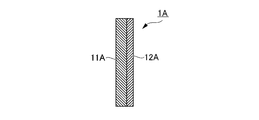
- FIG. 1 is a schematic view of a vertical cross section parallel to the laminating direction of the composite material of the first aspect.
- the composite material 1A of the first aspect is formed by forming an antimony-doped tin oxide film 12A on one of the two surfaces of the plastic sheet base material 11A.
- the antimony-doped tin oxide film 12A is processed so that the emissivity is 0.65 or more and the solar radiation absorption rate is 40% or more.
- Such a composite material 1A can be used, for example, in an agricultural greenhouse.
- the constituent materials need to have translucency in order to collect light from the crops inside.
- a translucent material can be used as the plastic sheet base material 11A.
- the antimony-doped tin oxide film 12A also has translucency, the composite material as a whole also has translucency.
- heating may be used to prevent the temperature from dropping and frosting, or to maintain an appropriate temperature for year-round cultivation.
- the efficiency of heating can be increased and the productivity of agricultural products can be increased.
- the composite material 1A When the composite material 1A is used for an agricultural greenhouse or the like, when the composite material 1A is used to separate the room from the outside air, even if the plastic sheet base material 11A is arranged on the outside air side, the antimony-doped tin oxide film 12A is applied. It may be arranged on the outside air side.
- a protective layer may be formed on the surface of the antimony-doped tin oxide film 12A (the surface that is not adhered to the plastic sheet base material 11A) (shown). Z).
- the protective layer for example, a plastic sheet, PET (superimposition of base materials), glass coating, or the like can be used.
- FIG. 2 is a schematic view of a vertical cross section parallel to the laminating direction of the composite material of the second aspect.
- the composite material 1B of the second aspect is formed by forming a blackbody paint film 12B on one of the two surfaces of the mortar base material 11B.
- the blackbody paint film 12B is processed so that the emissivity is 0.65 or more and the solar radiation absorption rate is 40% or more.
- Such a composite material 1B can be used for the outer wall of a building such as a house or a warehouse, and blocks or suppresses heat transfer inside the building (indoor) to maintain a substantially constant temperature for heating and cooling. It can increase efficiency.
- the blackbody paint film 12B is arranged on the outside air side.
- a protective layer may be formed on the surface of the blackbody paint film 12B (the surface that is not adhered to the mortar base material 11B) (not shown).
- the protective layer for example, a transparent paint, a glass coating, or the like can be used.
- FIG. 3 is a schematic view of a vertical cross section parallel to the laminating direction of the composite material of the third aspect.
- an antimony-doped tin oxide film 12C having an emissivity of 0.65 or more and a solar radiation absorption rate of 40% or more is formed on one of both surfaces of the glass base material 11C. Further has a glass base material 14C located opposite to the antimony-doped tin oxide film 12C with the air layer 13C in between.
- the heat insulation of the composite material 1C is derived from the low thermal conductivity of air as in the case of so-called double glazing. You can improve your sex.
- Such a composite material 1C has translucency because the glass base material 11C, the antimony-doped tin oxide coating 12C, and the glass base material 14C all have translucency, and is used for, for example, window glass. Can be used.
- FIG. 4 is a schematic view of a vertical cross section parallel to the laminating direction of the composite material of the fourth aspect.
- an antimony-doped tin oxide film 12D having an emissivity of 0.65 or more and a solar absorption rate of 40% or more is formed on one of both surfaces of the glass base material 11D.
- a glass base material 14D located opposite to the air layer 13D is further provided on the other side of the glass base material 11D on which the antimony-doped tin oxide film 12D is not formed.
- the difference between the composite material 1C of the third aspect and the composite material 1D of the fourth aspect is that in the composite material 1C of the third aspect described above, the surface facing the air layer 13C is the glass base material 11C.
- the surface facing the air layer 13D is the surface of both sides of the glass substrate 11D that is antimony. The other surface on which the dope tin oxide coating 12D is not formed.
- Such a composite material 1D has translucency because the glass base material 11D, the antimony-doped tin oxide coating 12D, and the glass base material 14D all have translucency, and can be used for, for example, window glass. Can be used.
- a blackbody paint is used instead of the antimony-doped tin oxide coatings 12C and 12D to be used as a translucent window glass. You can also.
- FIG. 5 is a schematic view of a vertical cross section parallel to the laminating direction of the composite material of the fifth aspect.
- a blackbody paint film 12E having an emissivity of 0.65 or more and a solar radiation absorption rate of 40% or more is formed on one of both surfaces of the heat-resistant glass base material 11E. Further, the black body paint film 12E and the glass base material 14E located opposite to each other with the air layer 13E in between are further provided.
- the composite material 1E can be used for a curtain wall or the like.
- tempered glass may be used instead of the heat-resistant glass base material 11E when it is placed at a higher temperature.
- FIG. 6 is a schematic view of a vertical cross section parallel to the laminating direction of the composite material of the sixth aspect.
- a blackbody paint film 12F having an emissivity of 0.65 or more and a solar radiation absorption rate of 40% or more is formed on one of both surfaces of the heat-resistant glass base material 11F.
- the black body paint film 12F and the glass base material 14F located opposite to each other with the air layer 13F in between are further provided.
- an aluminum film 15F having an emissivity of 0.5 or less is formed on the other surface of the heat-resistant glass base material 11F on which the blackbody paint film 12F is not formed.
- the composite material 1F of the sixth aspect is lower than that of the composite material 1E of the fifth aspect on both sides of the heat-resistant glass base material 11F on which the blackbody paint film 12F is not formed.
- An aluminum film 15F which is a radial film, is formed. By forming the aluminum film 15F in this way, it is possible to further enhance the heat insulating property when the heat source on one side is radiant heat and the heat insulating property in summer.
- the composite material shown above can be used as a heat insulating material. According to such a heat insulating material, it is possible to provide a material having higher heat insulating performance, thereby increasing the cooling / heating efficiency of the partitioned space and further reducing the amount of electricity used.
- a sample in which a silver layer and an aluminum layer were laminated was prepared and attached to a glass case to prepare a composite material of Comparative Example 1.
- the obtained composite material had an emissivity (on each side) of 0.6 and a solar absorptivity of 47%.
- Example 1 After applying the primer to all the surfaces of the glass case prepared in Comparative Example 1, the black body paint was repeatedly applied by spraying 2-3 times to prepare the composite material of Example 1.
- the obtained composite material had an emissivity (on each side) of 0.92 and a solar absorption rate of 95.60%.
- Example 2 Tungsten was vapor-deposited on all surfaces of the glass case prepared in Comparative Example 1 to prepare a composite material of Example 2.
- the obtained composite material had an emissivity (on each side) of 0.878 and a solar absorptivity of 45.50%.
- the glass cases of Examples 1 and 2 and Comparative Example 1 were placed in a sufficiently large room, four 60 W light bulbs were prepared as pseudo-suns on the upper surface of the glass case, and the upper surface of the glass case was about 2 MJ / m 2 (555 W / m). It was adjusted so that 2 ⁇ 60 minutes) of light was acquired.
- the outside of the glass case was the outside air, and the inside of the glass case was the inside.
- One 100W light bulb was installed inside the glass case, and the 100W light bulb was lit and heated once until the temperature inside the glass case became 21 ° C. higher than the outside of the glass case. When the temperature inside the glass case dropped by 1 ° C from here, the 100W bulb was turned on again. By repeating such an operation, the inside of the glass case maintained a temperature range of 20 to 21 ° C. higher than the outside of the glass case for 60 minutes, and the power consumption was recorded.
- FIG. 7 shows the time course (integration) of the power consumption of the 100 W light bulb when the inside of the glass case was maintained in a temperature range of 20 to 21 ° C. higher than the outside air for 60 minutes for the composite materials of Examples 1 and 2 and Comparative Example 1. Value) graph.
- Table 1 the emissivity and solar absorptivity of the high radiation coating in the composite materials of Examples 1 and 2 and Comparative Example 1 and the inside of the glass case were maintained in a temperature range of 20 to 21 ° C. higher than the outside air for 60 minutes.
- the power consumption (integrated value) of the 100W light bulb at that time is shown.
- FIG. 7 it was found that the composite materials of Examples 1 and 2 were superior in the ability to maintain the indoor temperature as compared with Comparative Example 1.
- the composite material of the present invention has high heat insulating performance, thereby increasing the cooling and heating efficiency of the partitioned space, and significantly reducing the amount of electricity used as compared with the conventional heat insulating material. ..
Landscapes
- Chemical & Material Sciences (AREA)
- Engineering & Computer Science (AREA)
- Life Sciences & Earth Sciences (AREA)
- Chemical Kinetics & Catalysis (AREA)
- General Chemical & Material Sciences (AREA)
- Geochemistry & Mineralogy (AREA)
- Materials Engineering (AREA)
- Organic Chemistry (AREA)
- Ceramic Engineering (AREA)
- Laminated Bodies (AREA)
- Surface Treatment Of Glass (AREA)
- Joining Of Glass To Other Materials (AREA)
Abstract
Le matériau composite selon la présente invention comprend au moins : un premier matériau de base ; et, sur au moins une des deux surfaces du premier matériau de base, un film de revêtement à haute émission qui présente une émissivité supérieure ou égale à 0,65, telle que mesurée conformément à JIS Z 8117:2002, et présente une absorptivité de rayonnement solaire de 40 % ou plus, telle que mesurée conformément à JIS A 5759:2016.
Applications Claiming Priority (2)
| Application Number | Priority Date | Filing Date | Title |
|---|---|---|---|
| JP2019218496A JP2022191538A (ja) | 2019-12-03 | 2019-12-03 | 複合材料 |
| JP2019-218496 | 2019-12-03 |
Publications (1)
| Publication Number | Publication Date |
|---|---|
| WO2021111949A1 true WO2021111949A1 (fr) | 2021-06-10 |
Family
ID=76222361
Family Applications (1)
| Application Number | Title | Priority Date | Filing Date |
|---|---|---|---|
| PCT/JP2020/043844 Ceased WO2021111949A1 (fr) | 2019-12-03 | 2020-11-25 | Matériau composite |
Country Status (2)
| Country | Link |
|---|---|
| JP (1) | JP2022191538A (fr) |
| WO (1) | WO2021111949A1 (fr) |
Citations (7)
| Publication number | Priority date | Publication date | Assignee | Title |
|---|---|---|---|---|
| JPS61179881A (ja) * | 1985-02-04 | 1986-08-12 | Ibiden Co Ltd | 金属基材の赤外線放射体とその製造方法 |
| JPS63129986U (fr) * | 1987-02-18 | 1988-08-25 | ||
| JPS63297245A (ja) * | 1987-05-29 | 1988-12-05 | Yasuro Kuratomi | 遠赤外線放射硝子 |
| JPH01129235U (fr) * | 1988-02-26 | 1989-09-04 | ||
| JP2010096485A (ja) * | 2008-04-23 | 2010-04-30 | Ishinoyu Co Ltd | 室内環境調整システム |
| WO2011108323A1 (fr) * | 2010-03-02 | 2011-09-09 | 株式会社ブリヂストン | Verre multicouche bloquant les radiations thermiques |
| JP2015189086A (ja) * | 2014-03-28 | 2015-11-02 | 崇治 二枝 | 断熱遮熱シート |
-
2019
- 2019-12-03 JP JP2019218496A patent/JP2022191538A/ja active Pending
-
2020
- 2020-11-25 WO PCT/JP2020/043844 patent/WO2021111949A1/fr not_active Ceased
Patent Citations (7)
| Publication number | Priority date | Publication date | Assignee | Title |
|---|---|---|---|---|
| JPS61179881A (ja) * | 1985-02-04 | 1986-08-12 | Ibiden Co Ltd | 金属基材の赤外線放射体とその製造方法 |
| JPS63129986U (fr) * | 1987-02-18 | 1988-08-25 | ||
| JPS63297245A (ja) * | 1987-05-29 | 1988-12-05 | Yasuro Kuratomi | 遠赤外線放射硝子 |
| JPH01129235U (fr) * | 1988-02-26 | 1989-09-04 | ||
| JP2010096485A (ja) * | 2008-04-23 | 2010-04-30 | Ishinoyu Co Ltd | 室内環境調整システム |
| WO2011108323A1 (fr) * | 2010-03-02 | 2011-09-09 | 株式会社ブリヂストン | Verre multicouche bloquant les radiations thermiques |
| JP2015189086A (ja) * | 2014-03-28 | 2015-11-02 | 崇治 二枝 | 断熱遮熱シート |
Also Published As
| Publication number | Publication date |
|---|---|
| JP2022191538A (ja) | 2022-12-28 |
Similar Documents
| Publication | Publication Date | Title |
|---|---|---|
| Li et al. | Fundamentals, materials, and applications for daytime radiative cooling | |
| Ao et al. | Preliminary experimental study of a specular and a diffuse surface for daytime radiative cooling | |
| Gentle et al. | A subambient open roof surface under the Mid‐Summer sun | |
| Al-Obaidi et al. | Passive cooling techniques through reflective and radiative roofs in tropical houses in Southeast Asia: A literature review | |
| Pacheco et al. | Energy efficient design of building: A review | |
| JP6181210B2 (ja) | 熱放射反射コーティングを有する板ガラス | |
| ES2873150T3 (es) | Luna con revestimiento reflectante de la radiación térmica | |
| Dang et al. | A visible transparent solar infrared reflecting film with a low long-wave emittance | |
| KR101901486B1 (ko) | 열발생 기기용 방열 보호구조와 풍력 발전유닛 | |
| JPH08500966A (ja) | 曇天冬季用太陽熱暖房建造物 | |
| US20220381524A1 (en) | Systems and Methods for Spectrally Selective Thermal Radiators with Partial Exposures to Both the Sky and the Terrestrial Environment | |
| Kim et al. | Optical and thermal filtering nanoporous materials for sub-ambient radiative cooling | |
| Xuan et al. | Development, testing, and evaluation of the daylighting, thermal, and energy-saving performance of semitransparent radiative cooling glass in cooling-dominated regions | |
| Kumar et al. | Study of various glass window and building wall materials in different climatic zones of India for energy efficient building construction | |
| Mainini et al. | Lean strategies for window retrofit of Italian office buildings: Impact on energy use, thermal and visual comfort | |
| Mandal et al. | Radiative cooling and thermoregulation in the earth's glow | |
| Degeorges et al. | Beyond cooling: Radiative thermoregulation in the Earth’s glow with micropatterned directional emitters | |
| JP2019066101A (ja) | 天空放射冷却装置 | |
| Huang et al. | A Janus Spectrally Selective Glazing Toward All‐Season Energy‐Efficient Windows | |
| JP2014523007A (ja) | 光透過を制御するための層配列 | |
| CN201864664U (zh) | 一种双银low-e玻璃 | |
| WO2021111949A1 (fr) | Matériau composite | |
| Kumar et al. | Study of various glass materials to provide adequate day lighting in office buildings of warm and humid climatic zone in India | |
| JP7320982B2 (ja) | 農業用ハウス | |
| CN102010139A (zh) | 可钢化双银low-e玻璃 |
Legal Events
| Date | Code | Title | Description |
|---|---|---|---|
| 121 | Ep: the epo has been informed by wipo that ep was designated in this application |
Ref document number: 20895322 Country of ref document: EP Kind code of ref document: A1 |
|
| NENP | Non-entry into the national phase |
Ref country code: DE |
|
| 122 | Ep: pct application non-entry in european phase |
Ref document number: 20895322 Country of ref document: EP Kind code of ref document: A1 |
|
| NENP | Non-entry into the national phase |
Ref country code: JP |