WO2021117507A1 - 非接触給電システム - Google Patents
非接触給電システム Download PDFInfo
- Publication number
- WO2021117507A1 WO2021117507A1 PCT/JP2020/044215 JP2020044215W WO2021117507A1 WO 2021117507 A1 WO2021117507 A1 WO 2021117507A1 JP 2020044215 W JP2020044215 W JP 2020044215W WO 2021117507 A1 WO2021117507 A1 WO 2021117507A1
- Authority
- WO
- WIPO (PCT)
- Prior art keywords
- coil
- relay power
- relay
- power transmission
- power receiving
- Prior art date
- Legal status (The legal status is an assumption and is not a legal conclusion. Google has not performed a legal analysis and makes no representation as to the accuracy of the status listed.)
- Ceased
Links
Images




Classifications
-
- H—ELECTRICITY
- H02—GENERATION; CONVERSION OR DISTRIBUTION OF ELECTRIC POWER
- H02J—ELECTRIC POWER NETWORKS; CIRCUIT ARRANGEMENTS OR SYSTEMS FOR SUPPLYING OR DISTRIBUTING ELECTRIC POWER; SYSTEMS FOR STORING ELECTRIC ENERGY
- H02J50/00—Circuit arrangements or systems for wireless supply or distribution of electric power
- H02J50/50—Circuit arrangements or systems for wireless supply or distribution of electric power using additional energy repeaters between transmitting devices and receiving devices
-
- H—ELECTRICITY
- H01—ELECTRIC ELEMENTS
- H01F—MAGNETS; INDUCTANCES; TRANSFORMERS; SELECTION OF MATERIALS FOR THEIR MAGNETIC PROPERTIES
- H01F38/00—Adaptations of transformers or inductances for specific applications or functions
- H01F38/14—Inductive couplings
-
- B—PERFORMING OPERATIONS; TRANSPORTING
- B60—VEHICLES IN GENERAL
- B60L—PROPULSION OF ELECTRICALLY-PROPELLED VEHICLES; SUPPLYING ELECTRIC POWER FOR AUXILIARY EQUIPMENT OF ELECTRICALLY-PROPELLED VEHICLES; ELECTRODYNAMIC BRAKE SYSTEMS FOR VEHICLES IN GENERAL; MAGNETIC SUSPENSION OR LEVITATION FOR VEHICLES; MONITORING OPERATING VARIABLES OF ELECTRICALLY-PROPELLED VEHICLES; ELECTRIC SAFETY DEVICES FOR ELECTRICALLY-PROPELLED VEHICLES
- B60L53/00—Methods of charging batteries, specially adapted for electric vehicles; Charging stations or on-board charging equipment therefor; Exchange of energy storage elements in electric vehicles
- B60L53/10—Methods of charging batteries, specially adapted for electric vehicles; Charging stations or on-board charging equipment therefor; Exchange of energy storage elements in electric vehicles characterised by the energy transfer between the charging station and the vehicle
- B60L53/12—Inductive energy transfer
-
- B—PERFORMING OPERATIONS; TRANSPORTING
- B60—VEHICLES IN GENERAL
- B60L—PROPULSION OF ELECTRICALLY-PROPELLED VEHICLES; SUPPLYING ELECTRIC POWER FOR AUXILIARY EQUIPMENT OF ELECTRICALLY-PROPELLED VEHICLES; ELECTRODYNAMIC BRAKE SYSTEMS FOR VEHICLES IN GENERAL; MAGNETIC SUSPENSION OR LEVITATION FOR VEHICLES; MONITORING OPERATING VARIABLES OF ELECTRICALLY-PROPELLED VEHICLES; ELECTRIC SAFETY DEVICES FOR ELECTRICALLY-PROPELLED VEHICLES
- B60L53/00—Methods of charging batteries, specially adapted for electric vehicles; Charging stations or on-board charging equipment therefor; Exchange of energy storage elements in electric vehicles
- B60L53/30—Constructional details of charging stations
-
- H—ELECTRICITY
- H02—GENERATION; CONVERSION OR DISTRIBUTION OF ELECTRIC POWER
- H02J—ELECTRIC POWER NETWORKS; CIRCUIT ARRANGEMENTS OR SYSTEMS FOR SUPPLYING OR DISTRIBUTING ELECTRIC POWER; SYSTEMS FOR STORING ELECTRIC ENERGY
- H02J50/00—Circuit arrangements or systems for wireless supply or distribution of electric power
- H02J50/05—Circuit arrangements or systems for wireless supply or distribution of electric power using capacitive coupling
-
- H—ELECTRICITY
- H02—GENERATION; CONVERSION OR DISTRIBUTION OF ELECTRIC POWER
- H02J—ELECTRIC POWER NETWORKS; CIRCUIT ARRANGEMENTS OR SYSTEMS FOR SUPPLYING OR DISTRIBUTING ELECTRIC POWER; SYSTEMS FOR STORING ELECTRIC ENERGY
- H02J50/00—Circuit arrangements or systems for wireless supply or distribution of electric power
- H02J50/10—Circuit arrangements or systems for wireless supply or distribution of electric power using inductive coupling
- H02J50/12—Circuit arrangements or systems for wireless supply or distribution of electric power using inductive coupling of the resonant type
-
- H—ELECTRICITY
- H02—GENERATION; CONVERSION OR DISTRIBUTION OF ELECTRIC POWER
- H02J—ELECTRIC POWER NETWORKS; CIRCUIT ARRANGEMENTS OR SYSTEMS FOR SUPPLYING OR DISTRIBUTING ELECTRIC POWER; SYSTEMS FOR STORING ELECTRIC ENERGY
- H02J50/00—Circuit arrangements or systems for wireless supply or distribution of electric power
- H02J50/40—Circuit arrangements or systems for wireless supply or distribution of electric power using two or more transmitting or receiving devices
-
- H—ELECTRICITY
- H02—GENERATION; CONVERSION OR DISTRIBUTION OF ELECTRIC POWER
- H02J—ELECTRIC POWER NETWORKS; CIRCUIT ARRANGEMENTS OR SYSTEMS FOR SUPPLYING OR DISTRIBUTING ELECTRIC POWER; SYSTEMS FOR STORING ELECTRIC ENERGY
- H02J50/00—Circuit arrangements or systems for wireless supply or distribution of electric power
- H02J50/50—Circuit arrangements or systems for wireless supply or distribution of electric power using additional energy repeaters between transmitting devices and receiving devices
- H02J50/502—Circuit arrangements or systems for wireless supply or distribution of electric power using additional energy repeaters between transmitting devices and receiving devices the energy repeater being integrated together with the emitter or the receiver
-
- Y—GENERAL TAGGING OF NEW TECHNOLOGICAL DEVELOPMENTS; GENERAL TAGGING OF CROSS-SECTIONAL TECHNOLOGIES SPANNING OVER SEVERAL SECTIONS OF THE IPC; TECHNICAL SUBJECTS COVERED BY FORMER USPC CROSS-REFERENCE ART COLLECTIONS [XRACs] AND DIGESTS
- Y02—TECHNOLOGIES OR APPLICATIONS FOR MITIGATION OR ADAPTATION AGAINST CLIMATE CHANGE
- Y02T—CLIMATE CHANGE MITIGATION TECHNOLOGIES RELATED TO TRANSPORTATION
- Y02T90/00—Enabling technologies or technologies with a potential or indirect contribution to GHG emissions mitigation
- Y02T90/10—Technologies relating to charging of electric vehicles
- Y02T90/12—Electric charging stations
Definitions
- This disclosure relates to a non-contact power supply system.
- a non-contact power supply system for vehicles has a first capacitor, a transmission coil for transmitting AC power, a transmitter having a first resonance frequency defined by the transmission coil and the first capacitor, and a second capacitor.
- a power receiver having a power receiving coil that receives AC power and having a second resonance frequency defined by the power receiving coil and the second capacitor, and an AC power received from the power transmitting coil are transmitted to the power receiving coil. It is equipped with a repeater.
- the repeater is a relay power receiving coil unit for receiving AC power transmitted from the transmission coil, and is a first for forming a first self-resonant frequency which is the same frequency as the first resonance frequency.
- a relay power receiving coil unit including at least one coil that defines stray capacitance, and a relay power transmitting coil unit for transmitting AC power to the power receiver, which is the same frequency as the second resonance frequency. It may include a relay transmission coil unit including at least one coil that defines a second stray capacitance for forming a resonant frequency.
- a repeater is provided to transmit the AC power received from the power transmission coil to the power reception coil.
- the relay power receiving coil portion of the repeater defines a first stray capacitance for forming a first self-resonant frequency, which is the same frequency as the first resonance frequency, by at least one coil.
- the relay power transmission coil unit defines a second stray capacitance for forming a second self-resonant frequency that is the same frequency as the second resonance frequency by at least one coil. Therefore, the repeater can receive AC power from the transmitter and transmit the AC power to the receiver without providing a capacitor. Therefore, the repeater can be miniaturized, and the degree of freedom in arranging the repeater can be improved.
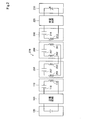
- FIG. 1 is an explanatory diagram showing the configuration of a contactless power supply system.
- FIG. 2 is an explanatory diagram showing a circuit configuration of a non-contact power supply system.
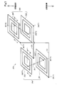
- FIG. 3 is an explanatory diagram showing the configuration of the coil included in the repeater.
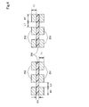
- FIG. 4 is a cross-sectional view of the IV-IV position of FIG.
- FIG. 5 is a cross-sectional view of the VV position of FIG.
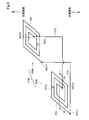
- FIG. 6 is an explanatory diagram showing the configuration of the coil of the repeater according to the second embodiment.
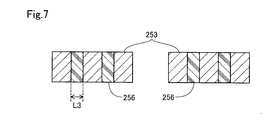
- FIG. 7 is a cross-sectional view of the VII-VII position of FIG. FIG.
- FIG. 8 is an explanatory diagram showing a circuit configuration of the non-contact power supply system of the second embodiment.
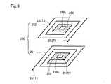
- FIG. 9 is a diagram showing a configuration of a relay power receiving coil unit in another embodiment.
- FIG. 10 is a diagram showing a configuration of a relay power receiving coil unit in another embodiment.
- FIG. 11 is a diagram showing a configuration of a relay power receiving coil unit in another embodiment.
- the non-contact power supply system 300 of the present embodiment is a system capable of non-contactly supplying electric power to the vehicle 200 from the transmitter 100.
- the non-contact power supply system 300 includes a transmitter 100 installed on the road RS, a receiver 205 mounted on the vehicle 200, and a repeater 270 that receives AC power from the transmitter 100 and transmits it to the receiver 205. including.
- the power transmission 100 includes a power transmission resonance circuit 110, a power transmission circuit 120, and a power supply circuit 130.
- the power transmission resonance circuit 110, the power transmission circuit 120, and the power supply circuit 130 are embedded inside the road RS.
- a plurality of the power transmission resonance circuit 110 and the power transmission circuit 120 may be provided, and the power transmission resonance circuit 110 and the power transmission circuit 120 may be continuously provided along the extending direction of the road RS, which is the traveling direction of the vehicle 200.
- the power transmission circuit 120 and the power supply circuit 130 do not need to be buried inside the road RS, and may be provided, for example, on the road RS at a position that does not adversely affect the traveling of the vehicle 200.
- the power transmission circuit 120 and the power supply circuit 130 are preferably provided in the vicinity of the power transmission resonance circuit 110.
- the power supply circuit 130 supplies DC power to the power transmission circuit 120.
- the power transmission circuit 120 is an AC conversion circuit having an inverter circuit and a filter circuit.
- the power transmission circuit 120 converts the DC power supplied from the power supply circuit 130 into high-frequency AC power and supplies it to the power transmission resonance circuit 110.
- the power transmission resonance circuit 110 transmits the AC power induced in the power transmission coil 112 to the relay power reception coil unit 250 of the repeater 270 by utilizing the electromagnetic induction phenomenon.
- the power transmission resonance circuit 110 includes a power transmission coil 112 and a first capacitor 116 that functions as a resonance capacitor.
- the resonance frequency defined by the electric capacity of the first capacitor 116 and the self-inductance of the power transmission coil 112 is also hereinafter referred to as the first resonance frequency.
- the vehicle 200 is composed of a vehicle equipped with a drive motor such as an electric vehicle or a hybrid vehicle, for example. As shown in FIG. 1, the vehicle 200 includes a repeater 270, a power receiver 205, and a battery 230.
- the power receiving device 205 has a power receiving resonance circuit 210 and a power receiving circuit 220.
- the power receiving resonance circuit 210 includes a power receiving coil 212 and a second capacitor 216 that functions as a resonance capacitor.
- the power receiving resonance circuit 210 receives the AC power induced in the relay power transmission coil unit 260 of the repeater 270 from the power receiving coil 212.
- the resonance frequency defined by the electric capacity of the second capacitor 216 and the self-inductance of the power receiving coil 212 is hereinafter also referred to as a second resonance frequency.
- the power receiving circuit 220 converts the AC power output from the power receiving resonance circuit 210 into DC power.
- the power receiving circuit 220 includes, for example, a filter circuit, a rectifier circuit that converts AC power into DC power, and a power conversion circuit that converts AC power into DC power suitable for charging the battery 230 as a load.
- the battery 230 is a secondary battery that outputs DC power for driving a drive motor that is a drive source of the vehicle 200.
- the DC power output from the power receiving circuit 220 can be used to charge the battery 230.
- the DC power from the power receiving circuit 220 may be used for charging an auxiliary battery (not shown) or driving a drive motor or auxiliary equipment.
- the repeater 270 transmits the AC power received from the power transmission resonance circuit 110 to the power reception resonance circuit 210.
- the repeater 270 includes a relay power receiving coil unit 250 that receives AC power transmitted from the power transmission coil 112, and a relay power transmission coil unit 260 that transmits AC power to the power receiver 205.
- the relay power receiving coil unit 250 includes two coils, a first relay power receiving coil 251 and a second relay power receiving coil 252, in the present embodiment.
- the relay power transmission coil unit 260 includes two coils, a first relay power transmission coil 261 and a second relay power transmission coil 262.
- the first relay power receiving coil 251 and the second relay power receiving coil 252, and the first relay power transmission coil 261 and the second relay power transmission coil 262 have a substantially flat plate shape, and the copper wiring has a substantially rectangular cross-sectional shape. Is formed by being wound multiple times.
- the first relay power receiving coil 251 and the second relay power receiving coil 252, and the first relay power transmission coil 261 and the second relay power transmission coil 262 can be obtained, for example, by cutting out a copper plate into a coil shape and molding it with resin. ..
- the repeater 270 includes a so-called open coil as shown in FIG. More specifically, one end 251T1 of the first relay power receiving coil 251 and one end 261T1 of the first relay power transmission coil 261 are electrically connected by wiring C1. The other end 251T2 of the first relay power receiving coil 251 and the other end 261T2 of the first relay power transmission coil 261 are open. One end 252T1 of the second relay power receiving coil 252 and one end 262T1 of the second relay power transmission coil 262 are electrically connected by wiring C2. The other end 252T2 of the second relay power receiving coil 252 and the other end 262T2 of the second relay power transmission coil 262 are open.
- the first relay power receiving coil 251 is a coil that is right-handed toward the coil center from one end 251T1 that is arranged on the outer peripheral side of the coil and is electrically connected to the first relay power transmission coil 261.
- the second relay power receiving coil 252 is a coil that is left-handed toward the center of the coil from one end 252T1 that is arranged on the outer peripheral side of the coil and is electrically connected to the second relay power transmission coil 262.
- the second relay power receiving coil 252 may be a coil that is right-handed from one end 252T1 toward the center of the coil.
- the configuration of each coil of the first relay power receiving coil 251 and the second relay power receiving coil 252 may be reversed.
- the first relay power receiving coil 251 is arranged on the outer peripheral side of the coil to transmit the first relay power. It is a left-handed coil from one end 251T1 electrically connected to the coil 261 toward the center of the coil, and the second relay power receiving coil 252 is arranged on the outer peripheral side of the coil and electrically connected to the second relay power transmitting coil 262.
- the coil may be right-handed from one end 252T1 toward the center of the coil.
- the combination of the coil configurations of the relay power receiving coil unit 250 including the first relay power receiving coil 251 and the second relay power receiving coil 252 is also referred to as a "first combination".
- the first relay power receiving coil 251 and the second relay power receiving coil 252 face each other in a state where their surfaces are parallel to each other, and are arranged at the lower part of the vehicle 200 in a state where their axes are aligned with each other.
- the first relay power receiving coil 251 is arranged below the vehicle 200, that is, on the transmitter 100 side of the second relay power receiving coil 252.
- the first relay power receiving coil 251 and the second relay power receiving coil 252 function as resonance coils for magnetic resonance with the power transmission coil 112.
- the width W1 in the vertical cross section of the conductor wiring constituting the coil is larger than the thickness T1.
- the distance L1 between the conductor wirings of the first relay power receiving coil 251 is larger than the distance G1 between the first relay power receiving coil 251 and the second relay power receiving coil 252.
- the distance G1 between the first relay power receiving coil 251 and the second relay power receiving coil 252 means the shortest distance between the first relay power receiving coil 251 and the second relay power receiving coil 252.
- the second relay power receiving coil 252 is also configured in the same manner as the first relay power receiving coil 251.
- the first relay power receiving coil 251 and the second relay power receiving coil 252 are fixed so close to each other that they generate stray capacitance connected in series. In other words, the distance G1 between the first relay power receiving coil 251 and the second relay power receiving coil 252 is adjusted so as to be small enough to generate stray capacitance in series.
- the stray capacitance generated in the first relay power receiving coil 251 and the second relay power receiving coil 252 includes the stray capacitance connected in series between the first relay power receiving coil 251 and the second relay power receiving coil 252, for example, of each coil. A stray capacitance is generated that is connected in parallel between the conductor wires.
- the stray capacitance in series is configured to be significantly larger than the stray capacitance in parallel, it is treated as generating only the stray capacitance in series.
- the combined capacitance of the stray capacitance in series generated between the first relay power receiving coil 251 and the second relay power receiving coil 252 is also hereinafter referred to as the first stray capacitance 257.
- a dielectric material 256 is arranged between the first relay power receiving coil 251 and the second relay power receiving coil 252.
- the dielectric material 256 is a ferroelectric material such as barium titanate.
- the dielectric material 256 may be a ferroelectric material, an ordinary dielectric material such as aluminum oxide or forsterite, or any dielectric material having a relative permittivity of 1 or more.
- the relay power receiving coil unit 250 has a first self-resonant frequency defined by a first relay power receiving coil 251, a second relay power receiving coil 252, and a first stray capacitance 257.
- the first self-resonant frequency is set to be the same as the first resonance frequency of the power transmission resonance circuit 110 of the power transmission 100.
- the series resonance frequency of the first self-resonance frequency is a frequency smaller than the parallel resonance frequency.
- the first relay power receiving coil 251 and the second relay power receiving coil 252 are magnetically coupled with the power transmission coil 112 to receive AC power from the power transmission 100.
- the relay power transmission coil unit 260 includes a first relay power transmission coil 261 and a second relay power transmission coil 262.
- the first relay power transmission coil 261 is a coil that is right-handed toward the coil center from one end 261T1 that is arranged on the outer peripheral side of the coil and is electrically connected to the first relay power transmission coil 261.
- the second relay power transmission coil 262 is a coil that is left-handed from one end 262T1 that is arranged on the outer peripheral side of the coil and is electrically connected to the second relay power reception coil 252 toward the center of the coil.
- the second relay power transmission coil 262 may be a coil that is right-handed from one end 262T1 toward the center of the coil.
- each coil of the first relay transmission coil 261 and the second relay transmission coil 262 may be reversed. More specifically, the first relay transmission coil 261 is arranged on the outer peripheral side of the coil to receive the first relay power. It is a coil that is left-handed from one end 261T1 that is electrically connected to the coil 251 toward the center of the coil, and the second relay transmission coil 262 is arranged on the outer peripheral side of the coil and is electrically connected to the second relay power receiving coil 252. The coil may be right-handed from one end 262T1 toward the center of the coil.
- the combination of the coil configurations of the relay power transmission coil unit 260 including the first relay power transmission coil 261 and the second relay power transmission coil 262 is also referred to as a "fourth combination".
- the first relay power transmission coil 261 and the second relay power transmission coil 262 are arranged in the vehicle 200 so that their surfaces are parallel to each other and their axes are aligned with each other.
- the second relay power transmission coil 262 is located closer to the power receiver 205 than the first relay power transmission coil 261 and is arranged so that the axes of the second relay power transmission coil 212 coincide with each other.
- the first relay power transmission coil 261 and the second relay power transmission coil 262 function as resonance coils for magnetic resonance with the power receiving coil 212.
- the axes of the first relay power transmission coil 261 and the second relay power transmission coil 262 do not have to coincide with the axes of the first relay power reception coil 251 and the second relay power reception coil 252.
- the width W2 in the vertical cross section of the conductor wiring constituting the coil is larger than the thickness T2.
- the distance L2 between the conductor wirings of the first relay power transmission coil 261 is larger than the distance G2 between the first relay power transmission coil 261 and the second relay power transmission coil 262.
- the distance G2 between the first relay power transmission coil 261 and the second relay power transmission coil 262 means the shortest distance between the first relay power transmission coil 261 and the second relay power transmission coil 262.
- the second relay power transmission coil 262 is also configured in the same manner as the first relay power transmission coil 261.
- the dielectric material 256 is arranged between the first relay power transmission coil 261 and the second relay power transmission coil 262.
- the first relay power transmission coil 261 and the second relay power transmission coil 262 are fixed so close to each other that they generate stray capacitance connected in series. In other words, the distance G2 between the first relay power transmission coil 261 and the second relay power transmission coil 262 is adjusted to be small enough to generate stray capacitance in series.
- the stray capacitance in series is configured to be significantly larger than the stray capacitance in parallel, it is treated as generating only the stray capacitance in series.
- the combined capacitance of the stray capacitance in series generated between the first relay transmission coil 261 and the second relay transmission coil 262 is also hereinafter referred to as the second stray capacitance 267.
- the relay power transmission coil unit 260 has a second self-resonant frequency defined by the first relay power transmission coil 261 and the second relay power transmission coil 262 and the second stray capacitance 267.
- the second self-resonant frequency is set to be the same as the second resonance frequency of the power receiving resonance circuit 210 of the power receiving device 205.
- the series resonance frequency of the second self-resonance frequency is a frequency smaller than the parallel resonance frequency.
- the first relay power transmission coil 261 and the second relay power transmission coil 262 magnetically couple with the power reception coil 212 to transmit AC power to the power receiver 205.
- the repeater 270 that transmits the AC power received from the power transmission coil 112 to the power reception coil 212 is provided.
- the relay power receiving coil unit 250 defines a first stray capacitance 257 for forming a first self-resonant frequency having the same frequency as the first resonance frequency by the first relay power receiving coil 251 and the second relay power receiving coil 252.
- the relay power transmission coil unit 260 has a second stray capacitance 267 for forming a second self-resonant frequency that is the same frequency as the second resonance frequency by the first relay power transmission coil 261 and the second relay power transmission coil 262.
- the repeater 270 can receive AC power from the transmitter 100 and transmit the AC power to the power receiver 205 without providing a capacitor. Therefore, the repeater 270 can be miniaturized, and the degree of freedom in arranging the repeater 270 can be improved.
- the first relay power receiving coil 251 and the second relay power receiving coil 252 that generate the first stray capacitance 257 connected in series are connected in series with the second stray capacitance. It includes an open type coil including a first relay transmission coil 261 for generating 267 and a second relay transmission coil 262. Since the relay power receiving coil unit 250 and the relay power transmission coil unit 260 are electrically connected, the axes of the relay power receiving coil unit 250 and the relay power transmission coil unit 260 are aligned with each other, for example, the relay power receiving coil unit 250 and the relay power transmission coil unit 260 are arranged apart from each other.
- the circuit design becomes easy.
- each coil of the relay power receiving coil unit 250 is composed of the first combination. More specifically, the first relay power receiving coil 251 is a coil that is right-handed from one end 251T1 on the outer peripheral side of the coil that is electrically connected, and the second relay power receiving coil 252 is the outer circumference of the coil that is electrically connected. It is a left-handed coil from one end 252T1 on the side. In each coil, one end side that is electrically connected is arranged on the outer peripheral side of the coil, so that the conductor wiring in the axial direction of each coil does not overlap. Therefore, it is possible to facilitate the processing of each coil from the copper plate.
- each coil of the relay power transmission coil unit 260 is composed of a fourth combination. More specifically, the first relay power transmission coil 261 is a right-handed coil from one end 261T1 on the outer peripheral side of the coil that is electrically connected, and the second relay power transmission coil 262 is the outer circumference of the coil that is electrically connected. It is a left-handed coil from one end 262T1 on the side. In each coil, one end side that is electrically connected is arranged on the outer peripheral side of the coil, so that the conductor wiring in the axial direction of each coil does not overlap. Therefore, it is possible to facilitate the processing of each coil from the copper plate.
- the width W1 in the vertical cross section of the conductor wiring in the first relay power receiving coil 251 is larger than the thickness T1.
- the area facing each other is large, and the area facing each other is small in each coil.
- the distance L1 between the conductor wirings of the first relay power receiving coil 251 is larger than the distance G1 between the first relay power receiving coil 251 and the second relay power receiving coil 252.
- the distance between the conductor wirings of the first relay power receiving coil 251 and the second relay power receiving coil 252 is reduced, and the distance between the conductor wirings is increased in each coil. Therefore, the first stray capacitance 257 connected in series between the first relay power receiving coil 251 and the second relay power receiving coil 252 can be increased.
- the width W2 in the vertical cross section of the conductor wiring in the first relay power transmission coil 261 is larger than the thickness T2.
- the area facing each other is increased, and the area facing each other is small in each coil.
- the distance L2 between the conductor wirings of the first relay power transmission coil 261 is larger than the distance G2 between the first relay power transmission coil 261 and the second relay power transmission coil 262.
- the distance between the first relay power transmission coil 261 and the second relay power transmission coil 262 is reduced, and the distance between the conductor wirings in each coil is increased. Therefore, the second stray capacitance 267 connected in series between the first relay power transmission coil 261 and the second relay power transmission coil 262 can be increased.
- the dielectric material 256 is arranged between the first relay power receiving coil 251 and the second relay power receiving coil 252, and between the first relay power transmission coil 261 and the second relay power transmission coil 262, The dielectric material 256 is arranged. Since the first stray capacitance 257 and the second stray capacitance 267 can be increased by the dielectric material 256, for example, the number of turns of each coil of the first relay transmission coil 261 and the second relay transmission coil 262 is reduced. be able to.
- the non-contact power feeding system 300 of the second embodiment includes a repeater 270b having a short-circuit coil.
- the non-contact power supply system 300 of the second embodiment is different from the non-contact power supply system 300 of the first embodiment in that the repeater 270b is provided instead of the repeater 270, and the other configurations are the non-contact power supply system 300 of the first embodiment. It is the same as the power supply system 300.
- the repeater 270b includes a relay power receiving coil unit 250b and a relay power transmission coil unit 260b.
- the relay power receiving coil unit 250b includes a third relay power receiving coil 253, and the relay power transmission coil unit 260b includes a third relay power transmission coil 263.
- the third relay power receiving coil 253 and the third relay power transmission coil 263 have a substantially flat plate shape, and are formed by winding copper wiring having a substantially rectangular cross-sectional shape a plurality of times. ..
- the third relay power receiving coil 253 and the third relay power transmission coil 263 can be obtained, for example, by cutting out a copper plate into a coil shape and filling the conductor wiring with a dielectric material 256.
- the third relay power receiving coil 253 and the third relay power transmitting coil 263 include a flat plate coil and a spring-shaped winding coil (also called a spring type coil) in which a conductor having a circular or square cross section is spirally wound.
- a spring-shaped winding coil also called a spring type coil
- various coils such as a laminated coil in which a plurality of flat plates are laminated may be used.
- the dielectric material 256 may be arranged at a corresponding position between the conductor wirings for each type of coil.
- the third relay power receiving coil 253 is arranged at the lower part of the vehicle 200.
- the third relay power transmission coil 263 is located closer to the power receiver 205 than the third relay power transmission coil 263, and is arranged so that the axes of the third relay power transmission coil 212 coincide with each other.
- the axis of the third relay power receiving coil 253 and the axis of the third relay power transmission coil 263 do not have to coincide with each other.
- one end 253T1 of the third relay power receiving coil 253 is electrically connected to one end 263T1 of the third relay power transmission coil 263 by the wiring C31.
- the third relay power receiving coil 253 is a right-handed coil from one end 253T1 which is arranged on the outer peripheral side of the coil and is electrically connected to the third relay power transmission coil 263.
- the other end 253T2 of the third relay power receiving coil 253 is electrically connected to the other end 263T2 of the third relay power transmission coil 263 by the wiring C32.
- the third relay power transmission coil 263 is a right-handed coil from one end 263T1 which is arranged on the outer peripheral side of the coil and is electrically connected to the third relay power reception coil 253.
- the distance L3 between the conductor wirings of the third relay power receiving coil 253 is adjusted to be small enough to generate stray capacitance connected in parallel.
- the dielectric material 256 is arranged between the conductor wirings of the third relay power receiving coil 253.
- the stray capacitance connected in parallel between the conductor wirings of the third relay power receiving coil 253 is increased. Since the configuration of the third relay power transmission coil 263 is the same as the configuration of the third relay power reception coil 253, the description thereof will be omitted.
- the combined capacitance of the parallel stray capacitance generated in the third relay power receiving coil 253 is also called the first stray capacitance 257b, and the combined capacitance of the parallel stray capacitance generated in the third relay power transmission coil 263 is also referred to as the second stray capacitance 267b.
- the repeater 270b can be represented by the circuit shown in FIG.
- the relay power receiving coil unit 250b has a first self-resonant frequency defined by a third relay power receiving coil 253 and a first stray capacitance 257b.
- the first self-resonant frequency is set to be the same as the first resonance frequency of the power transmission resonance circuit 110 of the power transmission 100.
- the third relay power receiving coil 253 functions as a resonance coil for magnetic resonance with the power transmission coil 112, and receives AC power from the power transmission 100 by being magnetically coupled with the power transmission coil 112.
- the relay power transmission coil unit 260b has a second self-resonant frequency defined by the third relay power transmission coil 263 and the second stray capacitance 267b.
- the second self-resonant frequency is set to be the same as the second resonance frequency of the power receiving resonance circuit 210 of the power receiving device 205.
- the third relay power transmission coil 263 functions as a resonance coil for magnetic resonance with the power receiving coil 212, and transmits AC power to the power receiving coil 205 by being magnetically coupled with the power receiving coil 212.
- the third relay power receiving coil 253 that generates the first stray capacitance 257b connected in parallel and the second stray capacitance 267b connected in parallel. It is provided with a short-type coil including a third relay transmission coil 263 for generating the above. Therefore, the AC power can be received from the transmitter 100 and the AC power can be transmitted to the power receiver 205 without providing the repeater 270b with a capacitor. Since the relay power receiving coil unit 250b and the relay power transmission coil unit 260b are electrically connected, positions where the axes of the relay power receiving coil unit 250b and the relay power transmission coil unit 260b do not match each other, such as being arranged apart from each other. It is possible to improve the degree of freedom of arrangement of the repeater 270b.
- the dielectric material 256 is arranged between the conductor wirings of the third relay power receiving coil 253 and between the conductor wirings of the third relay power transmission coil 263.
- the first stray capacitance 257b and the second stray capacitance 267b connected in parallel by the dielectric material 256 can be increased, for example, winding of each coil of the third relay power receiving coil 253 and the third relay power transmission coil 263. The number of turns can be reduced.
- the first conductive plate 259 is further provided at the center of the first relay power receiving coil 251 and the second relay power receiving coil.
- a second conductive plate 258 facing the first conductive plate 259 may be provided at the center of the 252. According to the non-contact power feeding system 300 of this form, the facing area between the conductor wirings of the first relay power receiving coil 251 and the second relay power receiving coil 252 can be increased, and the first stray capacitance connected in series can be increased. 257 can be increased.
- Each of the conductive plates 258 and 259 may be integrally formed with the coil in the processing at the time of forming the coil, or a flat conductor which is a separate body from the coil may be attached to the center of the coil.
- the first conductive plate 259 is provided with an opening 259c for passing the magnetic flux of the first relay power receiving coil 251 at a position serving as the axis of the first relay power receiving coil 251.
- the plate 258 is provided with an opening 258c for passing the magnetic flux of the second relay power receiving coil 252 at a position serving as the axis of the second relay power receiving coil 252.
- the conductive plates 258 and 259 may be provided with openings 258c and 259c, and may be arranged at positions that do not hinder the formation of magnetic flux in each coil.
- a third conductive plate is further provided at the center of the first relay power transmission coil 261 and a third conductive plate is provided at the center of the second relay power transmission coil 262.
- a fourth conductive plate facing the plate may be provided.
- the configurations of the third conductive plate and the fourth conductive plate may be the same as the configurations of the first conductive plate 259 and the second conductive plate 258. According to the non-contact power feeding system 300 of this form, the facing area between the conductor wirings of the first relay power transmission coil 261 and the second relay power transmission coil 262 can be increased, and the second stray capacitance 267 can be increased. Can be done.
- Each conductive plate may be formed integrally with the coil in the processing at the time of forming the coil, or a flat conductor which is a separate body from the coil may be attached to the center of the coil.
- the third conductive plate and the fourth conductive plate may be arranged at positions that do not hinder the formation of the magnetic flux of each coil, in addition to providing an opening.
- the first relay power receiving coil 251 and the second relay power receiving coil 252 of the relay power receiving coil unit 250 are configured by the first combination.
- the first relay power receiving coil 251 and the second relay power receiving coil 252 may be configured by the following second combination. More specifically, as shown in FIG. 10, the second relay power receiving coil 252 is right-handed toward the coil center from one end 252T1 which is arranged on the outer peripheral side of the coil and is electrically connected to the second relay power transmission coil 262. It is a coil of.
- the first relay power receiving coil 251 is a coil that is arranged on the outer peripheral side of the coil and is right-handed toward the center of the coil from the other end 251T2 that is opened.
- one end 251T1 of the first relay power receiving coil 251 may be extended from the center of the coil to the outer peripheral side of the coil.
- the first relay power receiving coil 251 may be a coil that is left-handed from the other end 251T2 toward the center of the coil.
- the configuration of each coil of the first relay power receiving coil 251 and the second relay power receiving coil 252 may be reversed. More specifically, the first relay power receiving coil 251 is arranged on the outer peripheral side of the coil to transmit the first relay power.
- the coil may be right-handed from one end 251T1 electrically connected to the coil 261 toward the coil center, and the second relay power receiving coil 252 is arranged on the outer peripheral side of the coil and is opened from the other end 252T2 to the coil center. It may be a right-handed coil toward.
- the first relay power receiving coil 251 and the second relay power receiving coil 252 of the relay power receiving coil unit 250 are configured by the first combination.
- the first relay power receiving coil 251 and the second relay power receiving coil 252 may be configured by the following third combination. More specifically, as shown in FIG. 11, the second relay power receiving coil 252 is a coil that is left-handed toward the center of the coil from the other end 252T2 that is arranged and opened on the outer peripheral side of the coil. As shown in FIG. 11, one end 252T1 of the second relay power receiving coil 252 may be extended from the center of the coil to the outer peripheral side of the coil.
- the first relay power receiving coil 251 is a coil that is arranged on the outer peripheral side of the coil and is right-handed toward the center of the coil from the other end 251T2 that is opened. As shown in FIG. 11, one end 251T1 of the first relay power receiving coil 251 may be extended from the center of the coil to the outer peripheral side of the coil.
- the first relay power receiving coil 251 may be a coil that is left-handed from the other end 251T2 toward the center of the coil.
- the configuration of each coil of the first relay power receiving coil 251 and the second relay power receiving coil 252 may be reversed, and more specifically, the first relay power receiving coil 251 is arranged and opened on the outer peripheral side of the coil.
- the second relay power receiving coil 252 is a right-handed coil from the other end 252T2 which is arranged and opened on the outer peripheral side of the coil and is opened toward the coil center. Good.
- the first relay power transmission coil 261 and the second relay power transmission coil 262 of the relay power transmission coil unit 260 are configured by a fourth combination.
- the first relay power transmission coil 261 and the second relay power transmission coil 262 may be configured by the following fifth combination.
- the second relay power transmission coil 262 is a coil that is right-handed toward the center of the coil from one end 262T1 that is arranged on the outer peripheral side of the coil and is electrically connected to the second relay power transmission coil 262.
- the first relay power transmission coil 261 is a coil that is arranged on the outer peripheral side of the coil and is right-handed toward the center of the coil from the other end 261T2 that is opened.
- the first relay power transmission coil 261 may be extended from the center of the coil to the outer peripheral side of the coil.
- the first relay power transmission coil 261 may be a coil that is left-handed from the other end 261T2 toward the center of the coil.
- the configuration of each coil of the first relay transmission coil 261 and the second relay transmission coil 262 may be reversed. More specifically, the first relay transmission coil 261 is arranged on the outer peripheral side of the coil to receive the first relay power.
- the coil may be right-handed from one end 261T1 electrically connected to the coil 251 toward the coil center, and the second relay transmission coil 262 is arranged on the outer peripheral side of the coil and is opened from the other end 262T2 to the coil center. It may be a right-handed coil toward.
- the first relay power transmission coil 261 and the second relay power transmission coil 262 of the relay power transmission coil unit 260 are configured by a fourth combination.
- the first relay power transmission coil 261 and the second relay power transmission coil 262 may be configured by the following sixth combination.
- the second relay power transmission coil 262 is a coil that is left-handed toward the center of the coil from the other end 262T2 that is arranged and opened on the outer peripheral side of the coil.
- One end 262T1 of the second relay power transmission coil 262 may be extended from the center of the coil to the outer peripheral side of the coil.
- the first relay power transmission coil 261 is a coil that is arranged on the outer peripheral side of the coil and is right-handed toward the center of the coil from the other end 261T2 that is opened.
- One end 261T1 of the first relay power transmission coil 261 may be extended from the center of the coil to the outer peripheral side of the coil.
- the first relay power transmission coil 261 may be a coil that is left-handed from the other end 261T2 toward the center of the coil.
- the configuration of each coil of the first relay transmission coil 261 and the second relay transmission coil 262 may be reversed, and more specifically, the first relay transmission coil 261 is arranged and opened on the outer peripheral side of the coil.
- the second relay transmission coil 262 is a right-handed coil from the other end 262T2 which is arranged and opened on the outer peripheral side of the coil and is opened toward the coil center. Good.
- the relay power receiving coil units 250 and 250b are arranged at the lower part of the vehicle 200, but the relay power receiving coil units 250 and 250b are the vehicle 200 such as tires and wheels of the vehicle 200, for example. It may be arranged at an arbitrary position where it can be magnetically coupled with the power transmission resonance circuit 110.
- the relay power transmission coil units 260 and 260b may be arranged at arbitrary positions of the vehicle 200 that can be magnetically coupled to the power receiving resonance circuit 210. Both the relay power receiving coil unit and the relay power transmission coil unit may be arranged on the road RS.
- the first relay power receiving coil 251 and the second relay power receiving coil 252 show an example in which the width W1 in the vertical cross section of the conductor wiring constituting the coil is shown, and the first relay power transmission coil 261 is shown.
- the second relay transmission coil 262 an example in which the width W2 of the conductor wiring is shown is shown.
- the first relay power transmitting coil 261 and the second relay power transmitting coil 262 for example, the width on the outer peripheral side of the coil.
- the width on the outer peripheral side of the coil and the width on the center side of the coil may be set differently so that the stray capacitance in series becomes larger, such as the width on the center side of the coil being larger than that on the center side of the coil. According to the non-contact power feeding system 300 of this form, the stray capacitance connected in series can be increased without changing the outer area of the coil.
- the width W1 in the vertical cross section of the conductor wiring is larger than the thickness T1, and the distance L1 between the conductor wirings is the same as that of the first relay power receiving coil 251.
- An example in which the distance from the second relay power receiving coil 252 is larger than G1 is shown.
- the width W1 in the vertical cross section of the conductor wiring may be smaller than the thickness T1, and the distance L1 between the conductor wirings is the first relay power receiving coil 251 and the second.
- the distance from the relay power receiving coil 252 may be smaller than G1.
- the width W2 of the conductor wiring is larger than the thickness T2, and the distance L2 between the conductor wirings is the first relay power transmission coil 261 and the second relay power transmission.
- the distance to the coil 262 is larger than the distance G2 is shown.
- the width W2 of the conductor wiring is smaller than the thickness T2, and the distance L2 between the conductor wirings is the distance between the first relay power transmission coil 261 and the second relay power transmission coil 262. It may be smaller than G2.
- a dielectric material is used between the first relay power receiving coil 251 and the second relay power receiving coil 252, and between the first relay power transmission coil 261 and the second relay power transmission coil 262.
- the dielectric material 256 may not be arranged.
- the dielectric material 256 is arranged between the conductor wirings of the third relay power receiving coil 253, but the dielectric material 256 may not be arranged.
- one kind of dielectric material is used between the first relay power receiving coil 251 and the second relay power receiving coil 252, and between the first relay power transmission coil 261 and the second relay power transmission coil 262.
- An example in which the material 256 is arranged is shown.
- at least one of the space between the first relay power receiving coil 251 and the second relay power receiving coil 252 and between the first relay power transmitting coil 261 and the second relay power transmitting coil 262 is, for example, a coil center.
- Different ratios such as arranging a dielectric material having a high specific dielectric constant on the side and arranging a dielectric material having a lower specific dielectric constant than the coil center side on the outer peripheral side of the coil so that the floating capacitance in series becomes large.
- a plurality of dielectric materials having a dielectric constant may be arranged between the coils. According to this form of non-contact power feeding system 300, the stray capacitance connected in series can be increased.
- one end 251T1 of the first relay power receiving coil 251 is electrically connected to one end 262T1 of the second relay power transmission coil 262, and one end of the second relay power receiving coil 252.
- the 252T1 may be electrically connected to one end 261T1 of the first relay power transmission coil 261.
- the present disclosure is not limited to the above-described embodiment, and can be realized by various configurations within a range not deviating from the purpose.
- the technical features in the embodiments corresponding to the technical features described in the column of the outline of the invention may be used to solve some or all of the above-mentioned problems, or some or all of the above-mentioned effects. It is possible to replace or combine as appropriate to achieve this. Further, if the technical feature is not described as essential in the present specification, it can be deleted as appropriate.
Landscapes
- Engineering & Computer Science (AREA)
- Power Engineering (AREA)
- Computer Networks & Wireless Communication (AREA)
- Transportation (AREA)
- Mechanical Engineering (AREA)
- Electric Propulsion And Braking For Vehicles (AREA)
- Current-Collector Devices For Electrically Propelled Vehicles (AREA)
Abstract
非接触給電システムは、第一コンデンサ(116)と送電コイル(112)とを有し、第一共振周波数を有する送電器(100)と、第二コンデンサ(216)と受電コイル(212)とを有し、第二共振周波数を有する受電器(205)と、送電コイルから受電した交流電力を受電コイルに送電する中継器(270)と、を備える。中継器は、交流電力を受電するための中継受電コイル部(250)であって、第一共振周波数と同一の周波数である第一自己共振周波数を形成するための第一浮遊容量(257)を規定する少なくとも一のコイルを備える中継受電コイル部と、交流電力を送電するための中継送電コイル部(260)であって、第二共振周波数と同一の周波数である第二自己共振周波数を形成するための第二浮遊容量(267)を規定する少なくとも一のコイルを備える中継送電コイル部とを含んでよい。
Description
本出願は、2019年12月12日に出願された日本出願番号2019-224374号に基づくもので、ここにその記載内容を援用する。
本開示は、非接触給電システムに関する。
路面に配置される送電コイルから車両側の受電コイルに非接触で給電する電気自動車が知られている。このような電気自動車において、電力伝送効率を高くするために、車両中の送電コイルと受電コイルとの間となる位置に、コイルとコンデンサとを用いた共振回路を有する中継器を備える技術が知られている(例えば、国際公開第2011/108403号)。
このような中継器において、装置全体を小型化し、車両や路面への配置の自由度を向上したいといった要望がある。
本開示は、以下の形態として実現することが可能である。
本開示の一形態によれば、車両用の非接触給電システムが提供される。この非接触給電システムは、第一コンデンサと交流電力を送電する送電コイルとを有し、前記送電コイルと前記第一コンデンサとによって規定される第一共振周波数を有する送電器と、第二コンデンサと交流電力を受電する受電コイルとを有し、前記受電コイルと前記第二コンデンサとによって規定される第二共振周波数を有する受電器と、前記送電コイルから受電した交流電力を前記受電コイルに送電する中継器と、を備える。前記中継器は、前記送電コイルから送電される交流電力を受電するための中継受電コイル部であって、前記第一共振周波数と同一の周波数である第一自己共振周波数を形成するための第一浮遊容量を規定する少なくとも一のコイルを備える中継受電コイル部と、前記受電器に交流電力を送電するための中継送電コイル部であって、前記第二共振周波数と同一の周波数である第二自己共振周波数を形成するための第二浮遊容量を規定する少なくとも一のコイルを備える中継送電コイル部と、を含んでよい。
この形態の非接触給電システムによれば、送電コイルから受電した交流電力を受電コイルに送電する中継器が備えられる。中継器の中継受電コイル部は、少なくとも一のコイルによって、第一共振周波数と同一の周波数である第一自己共振周波数を形成するための第一浮遊容量を規定する。中継送電コイル部は、少なくとも一のコイルによって、第二共振周波数と同一の周波数となる第二自己共振周波数を形成するための第二浮遊容量を規定する。そのため、中継器は、コンデンサを備えることなく、送電器から交流電力を受電し、受電器に交流電力を送電することができる。したがって、中継器を小型化することができ、中継器の配置の自由度を向上することができる。
本開示についての上記目的およびその他の目的、特徴や利点は、添付の図面を参照しながら下記の詳細な記述により、より明確になる。その図面は、
図1は、非接触給電システムの構成を表す説明図であり、
図2は、非接触給電システムの回路構成を表す説明図であり、
図3は、中継器に含まれるコイルの構成を表す説明図であり、
図4は、図3のIV-IV位置の断面図であり、
図5は、図3のV-V位置の断面図であり、
図6は、第2実施形態での中継器のコイルの構成を表す説明図であり、
図7は、図6のVII-VII位置の断面図であり、
図8は、第2実施形態の非接触給電システムの回路構成を表す説明図であり、
図9は、他の実施形態での中継受電コイル部の構成を表す図であり、
図10は、他の実施形態での中継受電コイル部の構成を表す図であり、
図11は、他の実施形態での中継受電コイル部の構成を表す図である。
A.第1実施形態:
図1および図2を用いて本実施形態の非接触給電システム300の構成について説明する。図1に示すように、本実施形態の非接触給電システム300は、送電器100から非接触で車両200に電力を供給することが可能なシステムである。非接触給電システム300は、道路RSに設置される送電器100と、車両200に搭載される受電器205と、送電器100からの交流電力を受電して受電器205に送電する中継器270とを含む。
図1および図2を用いて本実施形態の非接触給電システム300の構成について説明する。図1に示すように、本実施形態の非接触給電システム300は、送電器100から非接触で車両200に電力を供給することが可能なシステムである。非接触給電システム300は、道路RSに設置される送電器100と、車両200に搭載される受電器205と、送電器100からの交流電力を受電して受電器205に送電する中継器270とを含む。
送電器100は、送電共振回路110と、送電回路120と、電源回路130とを備えている。送電共振回路110と、送電回路120と、電源回路130とは、道路RSの内部に埋設されている。送電共振回路110および送電回路120は、複数を備えてよく、車両200の進行方向となる道路RSの延在方向に沿って連続的に備えられてよい。送電回路120および電源回路130は、道路RS内部に埋設されている必要はなく、例えば、道路RS上において、車両200の走行の弊害とならない位置に備えられてよい。送電回路120および電源回路130は、送電共振回路110近傍に備えられることが好ましい。
電源回路130は、直流電力を送電回路120に供給する。送電回路120は、インバータ回路やフィルタ回路を有する交流変換回路である。送電回路120は、電源回路130から供給される直流電力を高周波の交流電力に変換して送電共振回路110に供給する。
送電共振回路110は、電磁誘導現象を利用して送電コイル112に誘導された交流電力を中継器270の中継受電コイル部250に送電する。送電共振回路110は、図2に示すように、送電コイル112と、共振コンデンサとして機能する第一コンデンサ116とを含んでいる。第一コンデンサ116の電気容量と、送電コイル112の自己インダクタンスとによって規定される共振周波数を、以下、第一共振周波数とも呼ぶ。
車両200は、例えば、電気自動車やハイブリッド車等の駆動モータを搭載する車両で構成される。車両200は、図1に示すように、中継器270と、受電器205と、バッテリ230とを備えている。受電器205は、受電共振回路210と、受電回路220とを有している。
受電共振回路210は、図2に示すように、受電コイル212と、共振コンデンサとして機能する第二コンデンサ216とを含んでいる。受電共振回路210は、中継器270の中継送電コイル部260に誘導された交流電力を受電コイル212から受電する。第二コンデンサ216の電気容量と、受電コイル212の自己インダクタンスとによって規定される共振周波数を、以下、第二共振周波数とも呼ぶ。
受電回路220は、受電共振回路210から出力される交流電力を直流電力に変換する。受電回路220は、例えば、フィルタ回路と、交流電力を直流電力に変換する整流回路と、負荷としてのバッテリ230の充電に適した直流電力に変換する電力変換回路とを有する。バッテリ230は、車両200の駆動源である駆動モータを駆動するための直流電力を出力する2次電池である。受電回路220から出力される直流電力は、バッテリ230の充電に利用することができる。受電回路220からの直流電力は、図示しない補機バッテリの充電や、駆動モータや補機の駆動に利用されてよい。
中継器270は、送電共振回路110から受電した交流電力を、受電共振回路210に送電する。中継器270は、図1に示すように、送電コイル112から送電される交流電力を受電する中継受電コイル部250と、受電器205に交流電力を送電する中継送電コイル部260とを備える。
図3に示すように、中継受電コイル部250は、本実施形態において、第一中継受電コイル251と、第二中継受電コイル252との2つのコイルを備える。中継送電コイル部260は、第一中継送電コイル261と、第二中継送電コイル262との2つのコイルを備える。第一中継受電コイル251と第二中継受電コイル252、および第一中継送電コイル261と第二中継送電コイル262は、略平板状の形状を有しており、略矩形の断面形状を有する銅配線が複数回巻き回されて形成される。第一中継受電コイル251と第二中継受電コイル252、および第一中継送電コイル261と第二中継送電コイル262は、例えば、銅板をコイル状に切り出したものを樹脂モールドすることによって得ることができる。
本実施形態において、中継器270は、図3に示すように、いわゆるオープン方式のコイルを備えている。より具体的には、第一中継受電コイル251の一端251T1と第一中継送電コイル261の一端261T1とは、配線C1によって電気的に接続されている。第一中継受電コイル251の他端251T2および第一中継送電コイル261の他端261T2は、開放されている。第二中継受電コイル252の一端252T1と第二中継送電コイル262の一端262T1とは、配線C2によって電気的に接続されている。第二中継受電コイル252の他端252T2および第二中継送電コイル262の他端262T2は、開放されている。
第一中継受電コイル251は、図3に示すように、コイル外周側に配置され第一中継送電コイル261と電気的に接続される一端251T1からコイル中心に向かって右巻きのコイルである。第二中継受電コイル252は、コイル外周側に配置され第二中継送電コイル262と電気的に接続される一端252T1からコイル中心に向かって左巻きのコイルである。第二中継受電コイル252は、一端252T1からコイル中心に向かって右巻きのコイルであってもよい。第一中継受電コイル251と第二中継受電コイル252との各コイルの構成が逆であってよく、より具体的には、第一中継受電コイル251が、コイル外周側に配置され第一中継送電コイル261と電気的に接続される一端251T1からコイル中心に向かって左巻きのコイルであり、第二中継受電コイル252が、コイル外周側に配置され第二中継送電コイル262と電気的に接続される一端252T1からコイル中心に向かって右巻きのコイルであってよい。これら第一中継受電コイル251と第二中継受電コイル252とからなる中継受電コイル部250のコイル構成の組み合わせを、「第一の組み合わせ」とも呼ぶ。
第一中継受電コイル251と、第二中継受電コイル252とは、互いの面が平行な状態で対向し、互いの軸心が一致する状態で車両200の下部に配置されている。第一中継受電コイル251は、第二中継受電コイル252よりも車両200の下側、すなわち送電器100側に配置される。第一中継受電コイル251と第二中継受電コイル252とは、送電コイル112と磁気共鳴するための共振コイルとして機能する。
第一中継受電コイル251では、図4に示すように、コイルを構成する導体配線の垂直断面での幅W1が、厚みT1よりも大きい。第一中継受電コイル251の導体配線間の距離L1は、第一中継受電コイル251と第二中継受電コイル252との距離G1よりも大きい。第一中継受電コイル251と第二中継受電コイル252との距離G1とは、第一中継受電コイル251と第二中継受電コイル252との最短距離のことを意味する。第二中継受電コイル252も第一中継受電コイル251と同様に構成されている。
第一中継受電コイル251と第二中継受電コイル252とは、直列に接続される浮遊容量を発生させる程度に互いに近接した状態で固定されている。換言すれば、第一中継受電コイル251と第二中継受電コイル252との距離G1が、直列の浮遊容量を発生させる程度に小さくなるように調整されている。第一中継受電コイル251と第二中継受電コイル252とに発生する浮遊容量は、第一中継受電コイル251および第二中継受電コイル252間で直列に接続される浮遊容量のほか、例えば各コイルの導体配線間で並列に接続される浮遊容量が発生する。本実施形態において、直列の浮遊容量が、並列の浮遊容量よりも優位な程度に大きくなるように構成されているので、直列の浮遊容量のみを発生させるものとして扱う。第一中継受電コイル251と第二中継受電コイル252との間に発生する直列の浮遊容量の合成容量を、以下、第一浮遊容量257とも呼ぶ。
本実施形態において、図4に示すように、第一中継受電コイル251と第二中継受電コイル252との間には、誘電体材料256が配置されている。誘電体材料256は、例えばチタン酸バリウムのような強誘電体である。誘電体材料256は、強誘電体のほか、酸化アルミニウムやフォルステライトなどの常誘電体であってよく、比誘電率が1以上の任意の誘電体材料であってよい。
中継受電コイル部250は、第一中継受電コイル251と、第二中継受電コイル252と、第一浮遊容量257とによって規定される第一自己共振周波数を有する。第一自己共振周波数は、送電器100の送電共振回路110の第一共振周波数と同一となるように設定されている。第一自己共振周波数の直列共振周波数は、並列共振周波数よりも小さい周波数である。第一中継受電コイル251および第二中継受電コイル252は、送電コイル112と磁気結合して送電器100から交流電力を受電する。
図3に示すように、中継送電コイル部260は、第一中継送電コイル261と、第二中継送電コイル262とを備える。第一中継送電コイル261は、図3に示すように、コイル外周側に配置され第一中継送電コイル261と電気的に接続される一端261T1からコイル中心に向かって右巻きのコイルである。第二中継送電コイル262は、コイル外周側に配置され第二中継受電コイル252と電気的に接続される一端262T1からコイル中心に向かって左巻きのコイルである。第二中継送電コイル262は、一端262T1からコイル中心に向かって右巻きのコイルであってもよい。第一中継送電コイル261と第二中継送電コイル262との各コイルの構成が逆であってよく、より具体的には、第一中継送電コイル261が、コイル外周側に配置され第一中継受電コイル251と電気的に接続される一端261T1からコイル中心に向かって左巻きのコイルであり、第二中継送電コイル262が、コイル外周側に配置され第二中継受電コイル252と電気的に接続される一端262T1からコイル中心に向かって右巻きのコイルであってよい。これら第一中継送電コイル261と第二中継送電コイル262とからなる中継送電コイル部260のコイル構成の組み合わせを、「第四の組み合わせ」とも呼ぶ。
第一中継送電コイル261と第二中継送電コイル262とは、互いの面が平行な状態で対向し、互いの軸心が一致する状態で車両200内に配置されている。第二中継送電コイル262は、第一中継送電コイル261よりも受電器205側に位置し、受電コイル212と互いの軸心が一致するように配置されている。第一中継送電コイル261と第二中継送電コイル262とは、受電コイル212と磁気共鳴するための共振コイルとして機能する。第一中継送電コイル261および第二中継送電コイル262の軸心と、第一中継受電コイル251および第二中継受電コイル252の軸心とは一致しなくともよい。
第一中継送電コイル261では、図5に示すように、コイルを構成する導体配線の垂直断面での幅W2が、厚みT2よりも大きい。第一中継送電コイル261の導体配線間の距離L2は、第一中継送電コイル261と第二中継送電コイル262との距離G2よりも大きい。第一中継送電コイル261と第二中継送電コイル262との距離G2とは、第一中継送電コイル261と第二中継送電コイル262との最短距離のことを意味する。第二中継送電コイル262も第一中継送電コイル261と同様に構成されている。本実施形態において、第一中継送電コイル261と第二中継送電コイル262との間には、誘電体材料256が配置されている。
第一中継送電コイル261と第二中継送電コイル262とは、直列に接続される浮遊容量を発生させる程度に互いに近接した状態で固定されている。換言すれば、第一中継送電コイル261と第二中継送電コイル262との距離G2が、直列の浮遊容量を発生させる程度に小さくなるように調整されている。本実施形態において、直列の浮遊容量が、並列の浮遊容量よりも優位な程度に大きくなるように構成されているので、直列の浮遊容量のみを発生させるものとして扱う。第一中継送電コイル261と第二中継送電コイル262との間に発生する直列の浮遊容量の合成容量を、以下、第二浮遊容量267とも呼ぶ。
中継送電コイル部260は、第一中継送電コイル261と、第二中継送電コイル262と、第二浮遊容量267とによって規定される第二自己共振周波数を有する。第二自己共振周波数は、受電器205の受電共振回路210の第二共振周波数と同一となるように設定されている。第二自己共振周波数の直列共振周波数は、並列共振周波数よりも小さい周波数である。第一中継送電コイル261および第二中継送電コイル262は、受電コイル212と磁気結合して受電器205に交流電力を送電する。
以上説明したように、本実施形態の非接触給電システム300によれば、送電コイル112から受電した交流電力を受電コイル212に送電する中継器270が備えられる。中継受電コイル部250は、第一中継受電コイル251と第二中継受電コイル252とによって、第一共振周波数と同一の周波数となる第一自己共振周波数を形成するための第一浮遊容量257を規定する。中継送電コイル部260は、第一中継送電コイル261と、第二中継送電コイル262とによって、第二共振周波数と同一の周波数となる第二自己共振周波数を形成するための第二浮遊容量267を規定する。そのため、中継器270は、コンデンサを備えることなく、送電器100から交流電力を受電し、受電器205に交流電力を送電することができる。したがって、中継器270を小型化することができ、中継器270の配置の自由度を向上することができる。
本実施形態の非接触給電システム300によれば、直列に接続される第一浮遊容量257を発生させる第一中継受電コイル251と第二中継受電コイル252と、直列に接続される第二浮遊容量267を発生させる第一中継送電コイル261と第二中継送電コイル262とを含むオープン方式のコイルを備えている。中継受電コイル部250と中継送電コイル部260とが電気的に接続されるので、例えば、中継受電コイル部250と中継送電コイル部260とを互いに離間して配置するなど、互いの軸心が一致しない位置に配置することができるので、中継器270の配置の自由度を向上することができる。中継受電コイル部250と中継送電コイル部260とは、直列の浮遊容量を利用して共振させるので、回路設計が容易となる。
本実施形態の非接触給電システム300によれば、中継受電コイル部250の各コイルが第一の組み合わせで構成されている。より具体的には、第一中継受電コイル251は、電気的に接続されるコイル外周側の一端251T1から右巻きのコイルであり、第二中継受電コイル252は、電気的に接続されるコイル外周側の一端252T1から左巻きのコイルである。各コイルにおいて、電気的に接続される一端側がコイル外周側に配置されているので、各コイルの軸方向での導体配線の重複が発生しない。したがって、各コイルの銅板からの加工を容易にすることができる。
本実施形態の非接触給電システム300によれば、中継送電コイル部260の各コイルが第四の組み合わせで構成されている。より具体的には、第一中継送電コイル261は、電気的に接続されるコイル外周側の一端261T1から右巻きのコイルであり、第二中継送電コイル262は、電気的に接続されるコイル外周側の一端262T1から左巻きのコイルである。各コイルにおいて、電気的に接続される一端側がコイル外周側に配置されているので、各コイルの軸方向での導体配線の重複が発生しない。したがって、各コイルの銅板からの加工を容易にすることができる。
本実施形態の非接触給電システム300によれば、第一中継受電コイル251における導体配線の垂直断面での幅W1が、厚みT1よりも大きい。第一中継受電コイル251と第二中継受電コイル252との導体配線において、互いに対向し合う面積が大きくされ、各コイルにおいて導体配線間で対向する面積が小さく構成されている。第一中継受電コイル251の導体配線間の距離L1は、第一中継受電コイル251と第二中継受電コイル252との距離G1よりも大きい。第一中継受電コイル251と第二中継受電コイル252との導体配線間の距離が小さくされ、各コイルにおいて導体配線間の距離が大きくなるように構成されている。したがって、第一中継受電コイル251と第二中継受電コイル252とで直列に接続される第一浮遊容量257を大きくすることができる。
本実施形態の非接触給電システム300によれば、第一中継送電コイル261における導体配線の垂直断面での幅W2が、厚みT2よりも大きい。第一中継送電コイル261と第二中継送電コイル262との導体配線において、互いに対向し合う面積が大きくされ、各コイルにおいて導体配線間で対向する面積が小さく構成されている。第一中継送電コイル261の導体配線間の距離L2は、第一中継送電コイル261と第二中継送電コイル262との距離G2よりも大きい。第一中継送電コイル261と第二中継送電コイル262との間の距離が小さくされ、各コイルにおいて導体配線間の距離が大きくなるように構成されている。したがって、第一中継送電コイル261と第二中継送電コイル262とで直列に接続される第二浮遊容量267を大きくすることができる。
本実施形態の非接触給電システム300によれば、第一中継受電コイル251と第二中継受電コイル252との間、および第一中継送電コイル261と第二中継送電コイル262との間には、誘電体材料256が配置されている。誘電体材料256によって第一浮遊容量257および第二浮遊容量267を大きくすることができるので、例えば、第一中継送電コイル261と第二中継送電コイル262との各コイルの巻き回し数を削減することができる。
B.第2実施形態:
第2実施形態の非接触給電システム300では、ショート方式のコイルを有する中継器270bを備えている。第2実施形態の非接触給電システム300は、中継器270に代えて中継器270bを備える点で第1実施形態の非接触給電システム300と相違し、その他の構成は第1実施形態の非接触給電システム300と同様である。図6に示すように、中継器270bは、中継受電コイル部250bと、中継送電コイル部260bとを備える。
第2実施形態の非接触給電システム300では、ショート方式のコイルを有する中継器270bを備えている。第2実施形態の非接触給電システム300は、中継器270に代えて中継器270bを備える点で第1実施形態の非接触給電システム300と相違し、その他の構成は第1実施形態の非接触給電システム300と同様である。図6に示すように、中継器270bは、中継受電コイル部250bと、中継送電コイル部260bとを備える。
中継受電コイル部250bは、第三中継受電コイル253を備え、中継送電コイル部260bは、第三中継送電コイル263を備える。本実施形態において、第三中継受電コイル253および第三中継送電コイル263は、略平板状の形状を有しており、略矩形の断面形状を有する銅配線が複数回巻き回されて形成される。第三中継受電コイル253および第三中継送電コイル263は、例えば、銅板をコイル状に切り出して、導体配線間に誘電体材料256を充填することによって得ることができる。第三中継受電コイル253および第三中継送電コイル263には、平板状のコイルのほか、断面形状が円形や角形の導体をらせんに巻き回したばね状の巻き線コイル(スプリング型コイルとも呼ばれる)や、平板状のコイルを複数積層した積層コイルなどの種々のコイルが用いられてよい。誘電体材料256は、コイルの種類ごとの導体配線間に対応する位置に配置されてよい。
第三中継受電コイル253は、車両200の下部に配置されている。第三中継送電コイル263は、第三中継送電コイル263よりも受電器205側に位置し、受電コイル212と互いの軸心が一致するように配置されている。第三中継受電コイル253の軸心と、第三中継送電コイル263の軸心とは一致しなくともよい。
図6に示すように、第三中継受電コイル253の一端253T1は、配線C31によって第三中継送電コイル263の一端263T1と電気的に接続されている。第三中継受電コイル253は、コイル外周側に配置され第三中継送電コイル263と電気的に接続される一端253T1から右巻きのコイルである。第三中継受電コイル253の他端253T2は、配線C32によって第三中継送電コイル263の他端263T2と電気的に接続されている。第三中継送電コイル263は、コイル外周側に配置され、第三中継受電コイル253と電気的に接続される一端263T1から右巻きのコイルである。
図7に示すように、第三中継受電コイル253の導体配線間の距離L3は、並列に接続される浮遊容量を発生させる程度に小さくなるように調整されている。本実施形態において、誘電体材料256は、第三中継受電コイル253の導体配線間に配置されている。このように、本実施形態では、第三中継受電コイル253の導体配線間において並列に接続される浮遊容量が大きくなるように構成されている。なお、第三中継送電コイル263の構成は、第三中継受電コイル253の構成と同様であるので説明を省略する。
第三中継受電コイル253に発生する並列の浮遊容量の合成容量を、第一浮遊容量257bとも呼び、第三中継送電コイル263に発生する並列の浮遊容量の合成容量を、第二浮遊容量267bとも呼ぶ。中継器270bは、図8に示す回路で表すことができる。
中継受電コイル部250bは、第三中継受電コイル253と、第一浮遊容量257bとによって規定される第一自己共振周波数を有する。第一自己共振周波数は、送電器100の送電共振回路110の第一共振周波数と同一となるように設定されている。第三中継受電コイル253は、送電コイル112と磁気共鳴するための共振コイルとして機能し、送電コイル112と磁気結合されることにより、送電器100から交流電力を受電する。
中継送電コイル部260bは、第三中継送電コイル263と、第二浮遊容量267bとによって規定される第二自己共振周波数を有する。第二自己共振周波数は、受電器205の受電共振回路210の第二共振周波数と同一となるように設定されている。第三中継送電コイル263は、受電コイル212と磁気共鳴するための共振コイルとして機能し、受電コイル212と磁気結合されることにより、受電器205に交流電力を送電する。
以上説明したように、本実施形態の非接触給電システム300によれば、並列に接続される第一浮遊容量257bを発生させる第三中継受電コイル253と、並列に接続される第二浮遊容量267bを発生させる第三中継送電コイル263とを含むショート方式のコイルを備えている。したがって、中継器270bにコンデンサを備えることなく、送電器100から交流電力を受電し、受電器205に交流電力を送電することができる。中継受電コイル部250bと中継送電コイル部260bとが電気的に接続されるので、中継受電コイル部250bと中継送電コイル部260bとを互いに離間して配置するなど、互いの軸心が一致しない位置に配置することができ、中継器270bの配置の自由度を向上することができる。
本実施形態の非接触給電システム300によれば、第三中継受電コイル253の導体配線間、および第三中継送電コイル263の導体配線間に、誘電体材料256が配置されている。誘電体材料256によって並列に接続される第一浮遊容量257bおよび第二浮遊容量267bを大きくすることができ、例えば、第三中継受電コイル253と、第三中継送電コイル263との各コイルの巻き回し数を削減することができる。
C.他の実施形態:
(C1)図9に示すように、上記第1実施形態での中継受電コイル部250において、更に、第一中継受電コイル251の中心に、第一導電板259が備えられ、第二中継受電コイル252の中心に、第一導電板259に対向する第二導電板258が備えられてもよい。この形態の非接触給電システム300によれば、第一中継受電コイル251と第二中継受電コイル252との導体配線間での対向面積を大きくすることができ、直列に接続される第一浮遊容量257を大きくすることができる。各導電板258,259は、コイルの形成時の加工においてコイルと一体的に形成されてもよく、コイルとは別体である平板状の導電体をコイル中心に取り付けてもよい。図9に示すように、第一導電板259には、第一中継受電コイル251の軸心となる位置に、第一中継受電コイル251の磁束を通すための開口259cが備えられ、第二導電板258には、第二中継受電コイル252の軸心となる位置に、第二中継受電コイル252の磁束を通すための開口258cが備えられる。各導電板258,259は、開口258c、259cを設けるほか、各コイルの磁束の形成を阻害しない位置に配置されてもよい。
(C1)図9に示すように、上記第1実施形態での中継受電コイル部250において、更に、第一中継受電コイル251の中心に、第一導電板259が備えられ、第二中継受電コイル252の中心に、第一導電板259に対向する第二導電板258が備えられてもよい。この形態の非接触給電システム300によれば、第一中継受電コイル251と第二中継受電コイル252との導体配線間での対向面積を大きくすることができ、直列に接続される第一浮遊容量257を大きくすることができる。各導電板258,259は、コイルの形成時の加工においてコイルと一体的に形成されてもよく、コイルとは別体である平板状の導電体をコイル中心に取り付けてもよい。図9に示すように、第一導電板259には、第一中継受電コイル251の軸心となる位置に、第一中継受電コイル251の磁束を通すための開口259cが備えられ、第二導電板258には、第二中継受電コイル252の軸心となる位置に、第二中継受電コイル252の磁束を通すための開口258cが備えられる。各導電板258,259は、開口258c、259cを設けるほか、各コイルの磁束の形成を阻害しない位置に配置されてもよい。
(C2)上記第1実施形態での中継送電コイル部260において、更に、第一中継送電コイル261の中心に、第三導電板が備えられ、第二中継送電コイル262の中心に、第三導電板に対向する第四導電板が備えられてもよい。第三導電板および第四導電板の構成は第一導電板259および第二導電板258の構成と同様であってよい。この形態の非接触給電システム300によれば、第一中継送電コイル261と第二中継送電コイル262との導体配線間での対向面積を大きくすることができ、第二浮遊容量267を大きくすることができる。各導電板は、コイルの形成時の加工においてコイルと一体的に形成されてもよく、コイルとは別体である平板状の導電体をコイル中心に取り付けてもよい。第三導電板および第四導電板は、開口を設けるほか、各コイルの磁束の形成を阻害しない位置に配置されてもよい。
(C3)上記第1実施形態において、中継受電コイル部250の第一中継受電コイル251と第二中継受電コイル252とが第一の組み合わせで構成されている。これに対して、図10に示すように、第一中継受電コイル251と第二中継受電コイル252とが、以下の第二の組み合わせで構成されていてもよい。より具体的には、図10に示すように、第二中継受電コイル252は、コイル外周側に配置され第二中継送電コイル262と電気的に接続される一端252T1からコイル中心に向かって右巻きのコイルである。第一中継受電コイル251は、コイル外周側に配置され、開放される他端251T2からコイル中心に向かって右巻きのコイルである。第一中継受電コイル251の一端251T1は、図10に示すように、コイル中心からコイル外周側に至るまで延伸されてよい。第一中継受電コイル251は、他端251T2からコイル中心に向かって左巻きのコイルであってもよい。第一中継受電コイル251と第二中継受電コイル252との各コイルの構成が逆であってよく、より具体的には、第一中継受電コイル251が、コイル外周側に配置され第一中継送電コイル261と電気的に接続される一端251T1からコイル中心に向かって右巻きのコイルであってよく、第二中継受電コイル252が、コイル外周側に配置され、開放される他端252T2からコイル中心に向かって右巻きのコイルであってよい。
(C4)上記第1実施形態において、中継受電コイル部250の第一中継受電コイル251と第二中継受電コイル252とが第一の組み合わせで構成されている。これに対して、図11に示すように、第一中継受電コイル251と第二中継受電コイル252とが、以下の第三の組み合わせで構成されていてもよい。より具体的には、図11に示すように、第二中継受電コイル252は、コイル外周側に配置され開放される他端252T2からコイル中心に向かって左巻きのコイルである。第二中継受電コイル252の一端252T1は、図11に示すように、コイル中心からコイル外周側に至るまで延伸されてよい。第一中継受電コイル251は、コイル外周側に配置され、開放される他端251T2からコイル中心に向かって右巻きのコイルである。第一中継受電コイル251の一端251T1は、図11に示すように、コイル中心からコイル外周側に至るまで延伸されてよい。第一中継受電コイル251は、他端251T2からコイル中心に向かって左巻きのコイルであってもよい。第一中継受電コイル251と第二中継受電コイル252との各コイルの構成が逆であってよく、より具体的には、第一中継受電コイル251が、コイル外周側に配置され開放される他端251T2からコイル中心に向かって左巻きのコイルであってよく、第二中継受電コイル252が、コイル外周側に配置され、開放される他端252T2からコイル中心に向かって右巻きのコイルであってよい。
(C5)上記第1実施形態において、中継送電コイル部260の第一中継送電コイル261と第二中継送電コイル262とが第四の組み合わせで構成されている。これに対して、第一中継送電コイル261と第二中継送電コイル262とが、以下の第五の組み合わせで構成されていてもよい。より具体的には、第二中継送電コイル262は、コイル外周側に配置され第二中継送電コイル262と電気的に接続される一端262T1からコイル中心に向かって右巻きのコイルである。第一中継送電コイル261は、コイル外周側に配置され、開放される他端261T2からコイル中心に向かって右巻きのコイルである。第一中継送電コイル261の一端261T1は、コイル中心からコイル外周側に至るまで延伸されてよい。第一中継送電コイル261は、他端261T2からコイル中心に向かって左巻きのコイルであってもよい。第一中継送電コイル261と第二中継送電コイル262との各コイルの構成が逆であってよく、より具体的には、第一中継送電コイル261が、コイル外周側に配置され第一中継受電コイル251と電気的に接続される一端261T1からコイル中心に向かって右巻きのコイルであってよく、第二中継送電コイル262が、コイル外周側に配置され、開放される他端262T2からコイル中心に向かって右巻きのコイルであってよい。
(C6)上記第1実施形態において、中継送電コイル部260の第一中継送電コイル261と第二中継送電コイル262とが第四の組み合わせで構成されている。これに対して、第一中継送電コイル261と第二中継送電コイル262とが、以下の第六の組み合わせで構成されていてもよい。より具体的には、第二中継送電コイル262は、コイル外周側に配置され開放される他端262T2からコイル中心に向かって左巻きのコイルである。第二中継送電コイル262の一端262T1は、コイル中心からコイル外周側に至るまで延伸されてよい。第一中継送電コイル261は、コイル外周側に配置され、開放される他端261T2からコイル中心に向かって右巻きのコイルである。第一中継送電コイル261の一端261T1は、コイル中心からコイル外周側に至るまで延伸されてよい。第一中継送電コイル261は、他端261T2からコイル中心に向かって左巻きのコイルであってもよい。第一中継送電コイル261と第二中継送電コイル262との各コイルの構成が逆であってよく、より具体的には、第一中継送電コイル261が、コイル外周側に配置され開放される他端261T2からコイル中心に向かって左巻きのコイルであってよく、第二中継送電コイル262が、コイル外周側に配置され、開放される他端262T2からコイル中心に向かって右巻きのコイルであってよい。
(C7)上記各実施形態において、中継受電コイル部250,250bは、車両200の下部に配置されているが、中継受電コイル部250,250bは、例えば、車両200のタイヤやホイールなど、車両200において送電共振回路110と磁気結合できる任意の位置に配置されてよい。中継送電コイル部260,260bは、受電共振回路210と磁気結合できる車両200の任意の位置に配置されてよい。中継受電コイル部および中継送電コイル部の双方が、道路RSに配置されてもよい。
(C8)上記第1実施形態において、第一中継受電コイル251および第二中継受電コイル252では、コイルを構成する導体配線の垂直断面での幅W1である例を示し、第一中継送電コイル261および第二中継送電コイル262では、導体配線の幅W2である例を示した。これに対して、第一中継受電コイル251、第二中継受電コイル252、第一中継送電コイル261、第二中継送電コイル262の少なくともいずれかの導体配線において、例えば、コイルの外周側での幅よりもコイルの中心側での幅の方が大きくなる等、直列の浮遊容量が大きくなるように、コイルの外周側の幅とコイルの中心側の幅とが異なるように設定されてよい。この形態の非接触給電システム300によれば、コイルの外形面積を変えることなく、直列に接続される浮遊容量を増大させることができる。
(C9)上記第1実施形態において、第一中継受電コイル251では、導体配線の垂直断面での幅W1が、厚みT1よりも大きく、導体配線間の距離L1は、第一中継受電コイル251と第二中継受電コイル252との距離G1よりも大きい例を示した。これに対して、第一中継受電コイル251では、導体配線の垂直断面での幅W1が、厚みT1よりも小さくてもよく、導体配線間の距離L1は、第一中継受電コイル251と第二中継受電コイル252との距離G1よりも小さくてもよい。
(C10)上記第1実施形態において、第一中継送電コイル261では、導体配線の幅W2が、厚みT2よりも大きく、導体配線間の距離L2は、第一中継送電コイル261と第二中継送電コイル262との距離G2よりも大きい例を示した。これに対して、第一中継送電コイル261では、導体配線の幅W2が、厚みT2よりも小さく、導体配線間の距離L2は、第一中継送電コイル261と第二中継送電コイル262との距離G2よりも小さくてもよい。
(C11)上記第1実施形態において、第一中継受電コイル251と第二中継受電コイル252との間、および第一中継送電コイル261と第二中継送電コイル262との間には、誘電体材料256が配置されているが、誘電体材料256は配置されていなくてもよい。
(C12)上記第2実施形態において、誘電体材料256が、第三中継受電コイル253の導体配線間に配置されているが、誘電体材料256は配置されていなくてもよい。
(C13)上記第1実施形態において、第一中継受電コイル251と第二中継受電コイル252との間、および第一中継送電コイル261と第二中継送電コイル262との間に一種類の誘電体材料256が配置されている例を示した。これに対して、第一中継受電コイル251と第二中継受電コイル252との間、第一中継送電コイル261と第二中継送電コイル262との間の少なくともいずれか一方には、例えば、コイル中心側に高い比誘電率を有する誘電体材料を配置し、コイル外周側にコイル中心側よりも低い比誘電率を有する誘電体材料を配置するなど、直列の浮遊容量が大きくなるように、異なる比誘電率を有する複数の誘電材料がコイル間に配置されてもよい。この形態の非接触給電システム300によれば、直列に接続される浮遊容量をより大きくさせることができる。
(C14)上記第一の組み合わせから第六の組み合わせにおいて、第一中継受電コイル251の一端251T1が、第二中継送電コイル262の一端262T1と電気的に接続され、第二中継受電コイル252の一端252T1が、第一中継送電コイル261の一端261T1と電気的に接続されてよい。
本開示は、上述の実施形態に限られるものではなく、その趣旨を逸脱しない範囲において種々の構成で実現することができる。例えば、発明の概要の欄に記載した技術的特徴に対応する実施形態中の技術的特徴は、上述の課題の一部又は全部を解決するために、あるいは、上述の効果の一部又は全部を達成するために、適宜、差し替えや、組み合わせを行うことが可能である。また、その技術的特徴が本明細書中に必須なものとして説明されていなければ、適宜、削除することが可能である。
Claims (13)
- 車両用の非接触給電システム(300)であって、
第一コンデンサ(116)と、交流電力を送電する送電コイル(112)とを有し、前記送電コイルと前記第一コンデンサとによって規定される第一共振周波数を有する送電器(100)と、
第二コンデンサ(216)と、交流電力を受電する受電コイル(212)とを有し、前記受電コイルと前記第二コンデンサとによって規定される第二共振周波数を有する受電器(205)と、
前記送電コイルから受電した交流電力を前記受電コイルに送電する中継器(270,270b)と、を備え、
前記中継器は、
前記送電コイルから送電される交流電力を受電するための中継受電コイル部(250,250b)であって、前記第一共振周波数と同一の周波数である第一自己共振周波数を形成するための第一浮遊容量(257,257b)を規定する少なくとも一のコイルを備える中継受電コイル部と、
前記受電器に交流電力を送電するための中継送電コイル部(260,260b)であって、前記第二共振周波数と同一の周波数である第二自己共振周波数を形成するための第二浮遊容量(267,267b)を規定する少なくとも一のコイルを備える中継送電コイル部と、を含む、
非接触給電システム。 - 請求項1に記載の非接触給電システムであって、
前記中継受電コイル部は、2つのコイルとして、第一中継受電コイル(251)と、前記第一中継受電コイルに対して前記受電器側で近接して対向し、直列に接続される前記第一浮遊容量を発生させるための第二中継受電コイル(252)とを備え、
前記中継送電コイル部は、2つのコイルとして、第一中継送電コイル(261)と、前記第一中継送電コイルに対して前記送電器側で近接して対向し、直列に接続される前記第二浮遊容量を発生させるための第二中継送電コイル(262)とを備え、
前記第一中継受電コイルの一端(251T1)と前記第一中継送電コイルの一端(261T1)とが電気的に接続され、前記第一中継受電コイルの他端(251T2)および前記第一中継送電コイルの他端(262T2)が開放され、
前記第二中継受電コイルの一端(252T1)と前記第二中継送電コイルの一端(262T1)とが電気的に接続され、前記第二中継受電コイルの他端(252T2)および前記第二中継送電コイルの他端(262T2)が開放され、
前記第一自己共振周波数の直列共振周波数は、前記送電コイルから送電される交流電力の周波数と一致するように設定され、前記第一自己共振周波数の並列共振周波数よりも小さい周波数であり、
前記第二自己共振周波数の直列共振周波数は、前記受電コイルが受電する交流電力の周波数と一致するように設定され、前記第二自己共振周波数の並列共振周波数よりも小さい周波数である、
非接触給電システム。 - 請求項2に記載の非接触給電システムであって、
前記中継受電コイル部の前記第一中継受電コイルおよび前記第二中継受電コイルは、
一方のコイルが、コイル外周側に配置され電気的に接続される一端から右巻きの平面状のコイルであり、他方のコイルが、電気的に接続される一端をコイル外周側に配置される平面状のコイルである第一の組み合わせと、
一方のコイルが、コイル外周側に配置され電気的に接続される一端から右巻きの平面状のコイルであり、他方のコイルが、開放される他端をコイル外周側に配置される平面状のコイルである第二の組み合わせと、
一方のコイルが、コイル外周側に配置され開放される他端から左巻きの平面状のコイルであり、他方のコイルが、開放される他端をコイル外周側に配置される平面状のコイルである第三の組み合わせと、の少なくともいずれかの組み合わせを有する、
非接触給電システム。 - 請求項2または請求項3に記載の非接触給電システムであって、
前記中継送電コイル部の前記第一中継送電コイルおよび前記第二中継送電コイルは、
一方のコイルが、コイル外周側に配置され電気的に接続される一端から右巻きの平面状のコイルであり、他方のコイルが、電気的に接続される一端をコイル外周側に配置される平面状のコイルである第四の組み合わせと、
一方のコイルが、コイル外周側に配置され電気的に接続される一端から右巻きの平面状のコイルであり、他方のコイルが、開放される他端をコイル外周側に配置される平面状のコイルである第五の組み合わせと、
一方のコイルが、コイル外周側に配置され開放される他端から左巻きの平面状のコイルであり、他方のコイルが、開放される他端をコイル外周側に配置される平面状のコイルである第六の組み合わせと、の少なくともいずれかの組み合わせを有する、
非接触給電システム。 - 請求項2から請求項4までのいずれか一項に記載の非接触給電システムであって、
前記中継受電コイル部は
前記第一中継受電コイルの中心に、第一導電板(259)が備えられ、
前記第二中継受電コイルの中心に、前記第一導電板に対向する第二導電板(258)が備えられる、
非接触給電システム。 - 請求項2から請求項5までのいずれか一項に記載の非接触給電システムであって、
前記中継送電コイル部は
前記第一中継送電コイルの中心に、第三導電板が備えられ、
前記第二中継送電コイルの中心に、前記第三導電板に対向する第四導電板が備えられる、
非接触給電システム。 - 請求項2から請求項6までのいずれか一項に記載の非接触給電システムであって、
前記中継受電コイル部と、前記中継送電コイル部との少なくともいずれか一方に含まれるコイルにおいて、コイル外周側の線幅とコイル中心側の線幅とが異なる、
非接触給電システム。 - 請求項2から請求項7までのいずれか一項に記載の非接触給電システムであって、
前記中継受電コイル部の前記第一中継受電コイルと、前記第二中継受電コイルとにおいて、
コイルを構成する導体の間の距離L1は、前記第一中継受電コイルと前記第二中継受電コイルとの最短距離G1よりも大きく、
導体の断面における幅W1は、導体の断面における厚みT1よりも大きい、
非接触給電システム。 - 請求項2から請求項8までのいずれか一項に記載の非接触給電システムであって、
前記中継送電コイル部の前記第一中継送電コイルと、前記第二中継送電コイルとにおいて、
コイルを構成する導体の間の距離L2は、前記第一中継送電コイルと前記第二中継送電コイルとの間の最短距離G2よりも大きく、
導体の断面における幅W2は、導体の断面における厚みT2よりも大きい、
非接触給電システム。 - 請求項2から請求項9までのいずれか一項に記載の非接触給電システムであって、
前記中継受電コイル部の前記第一中継受電コイルと前記第二中継受電コイルとの間、もしくは前記中継送電コイル部の前記第一中継送電コイルと前記第二中継送電コイルとの間の少なくともいずれか一方に、誘電体材料(256)が配置される、
非接触給電システム。 - 請求項10に記載の非接触給電システムであって、
前記誘電体材料は、異なる比誘電率を有する複数の誘電体材料を含む、
非接触給電システム。 - 請求項1に記載の非接触給電システムであって、
前記中継受電コイル部は、並列に接続される前記第一浮遊容量を発生させる第三中継受電コイル(253)を備え、
前記中継送電コイル部は、並列に接続される前記第二浮遊容量を発生させる第三中継送電コイル(263)を備え、
前記第三中継受電コイルの一端(253T1)と、前記第三中継送電コイルの一端(263T1)とが電気的に接続され、前記第三中継受電コイルの他端(253T2)と、前記第三中継送電コイルの他端(263T2)とが電気的に接続され、
前記第一自己共振周波数の並列共振周波数は、前記送電コイルから送電される交流電力の周波数と一致するように設定され、
前記第二自己共振周波数の並列共振周波数は、前記受電コイルが受電する交流電力の周波数と一致するように設定される、
非接触給電システム。 - 請求項12に記載の非接触給電システムであって、
前記中継受電コイル部の前記第三中継受電コイル、もしくは前記中継送電コイル部の前記第三中継送電コイルの少なくともいずれか一方において、コイルの線間に誘電体材料(256)が配置される、
非接触給電システム。
Priority Applications (3)
| Application Number | Priority Date | Filing Date | Title |
|---|---|---|---|
| EP20898414.6A EP4074535A4 (en) | 2019-12-12 | 2020-11-27 | CONTACTLESS POWER SUPPLY SYSTEM |
| CN202080086124.XA CN114788130A (zh) | 2019-12-12 | 2020-11-27 | 非接触供电系统 |
| US17/837,583 US12068619B2 (en) | 2019-12-12 | 2022-06-10 | Contactless power supply system |
Applications Claiming Priority (2)
| Application Number | Priority Date | Filing Date | Title |
|---|---|---|---|
| JP2019-224374 | 2019-12-12 | ||
| JP2019224374A JP7447457B2 (ja) | 2019-12-12 | 2019-12-12 | 非接触給電システム |
Related Child Applications (1)
| Application Number | Title | Priority Date | Filing Date |
|---|---|---|---|
| US17/837,583 Continuation US12068619B2 (en) | 2019-12-12 | 2022-06-10 | Contactless power supply system |
Publications (1)
| Publication Number | Publication Date |
|---|---|
| WO2021117507A1 true WO2021117507A1 (ja) | 2021-06-17 |
Family
ID=76310946
Family Applications (1)
| Application Number | Title | Priority Date | Filing Date |
|---|---|---|---|
| PCT/JP2020/044215 Ceased WO2021117507A1 (ja) | 2019-12-12 | 2020-11-27 | 非接触給電システム |
Country Status (5)
| Country | Link |
|---|---|
| US (1) | US12068619B2 (ja) |
| EP (1) | EP4074535A4 (ja) |
| JP (1) | JP7447457B2 (ja) |
| CN (1) | CN114788130A (ja) |
| WO (1) | WO2021117507A1 (ja) |
Cited By (1)
| Publication number | Priority date | Publication date | Assignee | Title |
|---|---|---|---|---|
| WO2024048061A1 (ja) * | 2022-09-01 | 2024-03-07 | トヨタ自動車株式会社 | 地上給電装置及び配線 |
Families Citing this family (5)
| Publication number | Priority date | Publication date | Assignee | Title |
|---|---|---|---|---|
| JP7454193B2 (ja) * | 2020-12-24 | 2024-03-22 | 株式会社デンソー | 受電装置 |
| WO2023069908A1 (en) * | 2021-10-18 | 2023-04-27 | Hevo Inc. | Systems and methods for dynamic roadway charging |
| JP7731107B2 (ja) * | 2022-05-18 | 2025-08-29 | 株式会社デンソー | 給電装置および給電システム |
| JP2024060471A (ja) | 2022-10-19 | 2024-05-02 | オムロン株式会社 | 非接触給電装置 |
| TWI912165B (zh) * | 2025-03-18 | 2026-01-11 | 亞福儲能股份有限公司 | 無線供電系統 |
Citations (3)
| Publication number | Priority date | Publication date | Assignee | Title |
|---|---|---|---|---|
| JP2011130614A (ja) * | 2009-12-18 | 2011-06-30 | Nissan Motor Co Ltd | 非接触給電装置 |
| WO2011108403A1 (ja) | 2010-03-04 | 2011-09-09 | 本田技研工業株式会社 | 電気自動車 |
| JP2016101079A (ja) * | 2014-11-26 | 2016-05-30 | パナソニックIpマネジメント株式会社 | 非接触給電システム |
Family Cites Families (9)
| Publication number | Priority date | Publication date | Assignee | Title |
|---|---|---|---|---|
| KR20040072581A (ko) * | 2004-07-29 | 2004-08-18 | (주)제이씨 프로텍 | 전자기파 증폭중계기 및 이를 이용한 무선전력변환장치 |
| JP4453741B2 (ja) | 2007-10-25 | 2010-04-21 | トヨタ自動車株式会社 | 電動車両および車両用給電装置 |
| JP5691458B2 (ja) * | 2010-03-31 | 2015-04-01 | 日産自動車株式会社 | 非接触給電装置及び非接触給電方法 |
| EP2632762B1 (en) * | 2010-10-29 | 2017-05-31 | Qualcomm Incorporated(1/3) | Wireless energy transfer via coupled parasitic resonators |
| WO2012086051A1 (ja) * | 2010-12-24 | 2012-06-28 | トヨタ自動車株式会社 | 非接触給電システム、車両、給電設備および非接触給電システムの制御方法 |
| JP2013021886A (ja) * | 2011-07-14 | 2013-01-31 | Sony Corp | 給電装置、給電システム、車両および電子機器 |
| KR101988009B1 (ko) * | 2012-03-23 | 2019-06-11 | 삼성전자주식회사 | 공진 주파수를 조정해서 커플링 효율을 높이는 무전전력 전송 시스템 및 방법 |
| KR20140011069A (ko) * | 2012-07-17 | 2014-01-28 | 한국전자통신연구원 | 무선 전력 전송 장치 |
| JP2015047046A (ja) * | 2013-08-29 | 2015-03-12 | トヨタ自動車株式会社 | 非接触電力伝送システム |
-
2019
- 2019-12-12 JP JP2019224374A patent/JP7447457B2/ja active Active
-
2020
- 2020-11-27 EP EP20898414.6A patent/EP4074535A4/en active Pending
- 2020-11-27 WO PCT/JP2020/044215 patent/WO2021117507A1/ja not_active Ceased
- 2020-11-27 CN CN202080086124.XA patent/CN114788130A/zh active Pending
-
2022
- 2022-06-10 US US17/837,583 patent/US12068619B2/en active Active
Patent Citations (3)
| Publication number | Priority date | Publication date | Assignee | Title |
|---|---|---|---|---|
| JP2011130614A (ja) * | 2009-12-18 | 2011-06-30 | Nissan Motor Co Ltd | 非接触給電装置 |
| WO2011108403A1 (ja) | 2010-03-04 | 2011-09-09 | 本田技研工業株式会社 | 電気自動車 |
| JP2016101079A (ja) * | 2014-11-26 | 2016-05-30 | パナソニックIpマネジメント株式会社 | 非接触給電システム |
Non-Patent Citations (1)
| Title |
|---|
| See also references of EP4074535A4 |
Cited By (1)
| Publication number | Priority date | Publication date | Assignee | Title |
|---|---|---|---|---|
| WO2024048061A1 (ja) * | 2022-09-01 | 2024-03-07 | トヨタ自動車株式会社 | 地上給電装置及び配線 |
Also Published As
| Publication number | Publication date |
|---|---|
| EP4074535A1 (en) | 2022-10-19 |
| US12068619B2 (en) | 2024-08-20 |
| US20220302766A1 (en) | 2022-09-22 |
| CN114788130A (zh) | 2022-07-22 |
| JP7447457B2 (ja) | 2024-03-12 |
| EP4074535A4 (en) | 2023-01-25 |
| JP2021093883A (ja) | 2021-06-17 |
Similar Documents
| Publication | Publication Date | Title |
|---|---|---|
| JP7447457B2 (ja) | 非接触給電システム | |
| US11577618B2 (en) | Wired/wireless integrated power reception system | |
| US9533592B2 (en) | Vehicle | |
| US9866058B2 (en) | Power feeding device, power receiving device, and wireless power transmission device | |
| CN102823110B (zh) | 非接触供电装置以及非接触供电方法 | |
| US20140225563A1 (en) | Power transmitting device, vehicle, and power transfer system | |
| JP7186698B2 (ja) | ワイヤレス電力送信機、ワイヤレス電力送信システム及びワイヤレス電力送信システム駆動方法 | |
| CN110073572A (zh) | 无线电力发射器,无线电力传输系统和用于驱动无线电力传输系统的方法 | |
| WO2011118404A1 (ja) | 給電装置 | |
| JPWO2012124029A1 (ja) | コイルユニット、車両、外部給電装置および車両充電システム | |
| WO2010038297A1 (ja) | 自己共振コイル、非接触電力伝達装置および車両 | |
| KR20120079799A (ko) | 자계 공명 방식의 비접촉 급전장치 | |
| JP2011167036A (ja) | 車両用給電装置および受電装置 | |
| US10230269B2 (en) | Contactless power supply system supplying power using power supply pad in contact less manner | |
| CN104541435B (zh) | 电力传输系统 | |
| WO2013054399A1 (ja) | 送電装置、受電装置、および電力伝送システム | |
| WO2014069445A1 (ja) | 電力伝送システム | |
| US20190260235A1 (en) | Wireless Power Transmitter, Wireless Power Transmission System and Method for Driving a Wireless Power Transmission System | |
| WO2013002240A1 (ja) | 給電システムの設計方法及び給電システム | |
| JP2013208012A (ja) | アンテナコイルユニット及び磁界共鳴式給電システム | |
| CN104426247A (zh) | 电力接收设备、电力发送设备和电力传输系统 | |
| WO2017056343A1 (ja) | 無線電力伝送システムおよび送電装置 | |
| US20150213950A1 (en) | Power receiving device and power transmitting device | |
| JP2014023324A (ja) | 電力搬送装置 | |
| WO2012086473A1 (en) | Resonance coil and contactless power transmission system incorporating the same resonance coil |
Legal Events
| Date | Code | Title | Description |
|---|---|---|---|
| 121 | Ep: the epo has been informed by wipo that ep was designated in this application |
Ref document number: 20898414 Country of ref document: EP Kind code of ref document: A1 |
|
| NENP | Non-entry into the national phase |
Ref country code: DE |
|
| ENP | Entry into the national phase |
Ref document number: 2020898414 Country of ref document: EP Effective date: 20220712 |