WO2021124627A1 - 合成装置及び合成方法 - Google Patents
合成装置及び合成方法 Download PDFInfo
- Publication number
- WO2021124627A1 WO2021124627A1 PCT/JP2020/034738 JP2020034738W WO2021124627A1 WO 2021124627 A1 WO2021124627 A1 WO 2021124627A1 JP 2020034738 W JP2020034738 W JP 2020034738W WO 2021124627 A1 WO2021124627 A1 WO 2021124627A1
- Authority
- WO
- WIPO (PCT)
- Prior art keywords
- reaction vessel
- solution
- gas
- carrier
- supplied
- Prior art date
- Legal status (The legal status is an assumption and is not a legal conclusion. Google has not performed a legal analysis and makes no representation as to the accuracy of the status listed.)
- Ceased
Links
Images


Classifications
-
- C—CHEMISTRY; METALLURGY
- C07—ORGANIC CHEMISTRY
- C07K—PEPTIDES
- C07K1/00—General methods for the preparation of peptides, i.e. processes for the organic chemical preparation of peptides or proteins of any length
- C07K1/04—General methods for the preparation of peptides, i.e. processes for the organic chemical preparation of peptides or proteins of any length on carriers
-
- B—PERFORMING OPERATIONS; TRANSPORTING
- B01—PHYSICAL OR CHEMICAL PROCESSES OR APPARATUS IN GENERAL
- B01F—MIXING, e.g. DISSOLVING, EMULSIFYING OR DISPERSING
- B01F33/00—Other mixers; Mixing plants; Combinations of mixers
- B01F33/40—Mixers using gas or liquid agitation, e.g. with air supply tubes
- B01F33/406—Mixers using gas or liquid agitation, e.g. with air supply tubes in receptacles with gas supply only at the bottom
-
- B—PERFORMING OPERATIONS; TRANSPORTING
- B01—PHYSICAL OR CHEMICAL PROCESSES OR APPARATUS IN GENERAL
- B01J—CHEMICAL OR PHYSICAL PROCESSES, e.g. CATALYSIS OR COLLOID CHEMISTRY; THEIR RELEVANT APPARATUS
- B01J19/00—Chemical, physical or physico-chemical processes in general; Their relevant apparatus
- B01J19/0046—Sequential or parallel reactions, e.g. for the synthesis of polypeptides or polynucleotides; Apparatus and devices for combinatorial chemistry or for making molecular arrays
-
- B—PERFORMING OPERATIONS; TRANSPORTING
- B01—PHYSICAL OR CHEMICAL PROCESSES OR APPARATUS IN GENERAL
- B01J—CHEMICAL OR PHYSICAL PROCESSES, e.g. CATALYSIS OR COLLOID CHEMISTRY; THEIR RELEVANT APPARATUS
- B01J4/00—Feed or outlet devices; Feed or outlet control devices
- B01J4/001—Feed or outlet devices as such, e.g. feeding tubes
-
- B—PERFORMING OPERATIONS; TRANSPORTING
- B01—PHYSICAL OR CHEMICAL PROCESSES OR APPARATUS IN GENERAL
- B01J—CHEMICAL OR PHYSICAL PROCESSES, e.g. CATALYSIS OR COLLOID CHEMISTRY; THEIR RELEVANT APPARATUS
- B01J8/00—Chemical or physical processes in general, conducted in the presence of fluids and solid particles; Apparatus for such processes
- B01J8/18—Chemical or physical processes in general, conducted in the presence of fluids and solid particles; Apparatus for such processes with fluidised particles
- B01J8/20—Chemical or physical processes in general, conducted in the presence of fluids and solid particles; Apparatus for such processes with fluidised particles with liquid as a fluidising medium
- B01J8/22—Chemical or physical processes in general, conducted in the presence of fluids and solid particles; Apparatus for such processes with fluidised particles with liquid as a fluidising medium gas being introduced into the liquid
-
- C—CHEMISTRY; METALLURGY
- C07—ORGANIC CHEMISTRY
- C07K—PEPTIDES
- C07K1/00—General methods for the preparation of peptides, i.e. processes for the organic chemical preparation of peptides or proteins of any length
- C07K1/02—General methods for the preparation of peptides, i.e. processes for the organic chemical preparation of peptides or proteins of any length in solution
-
- C—CHEMISTRY; METALLURGY
- C12—BIOCHEMISTRY; BEER; SPIRITS; WINE; VINEGAR; MICROBIOLOGY; ENZYMOLOGY; MUTATION OR GENETIC ENGINEERING
- C12M—APPARATUS FOR ENZYMOLOGY OR MICROBIOLOGY; APPARATUS FOR CULTURING MICROORGANISMS FOR PRODUCING BIOMASS, FOR GROWING CELLS OR FOR OBTAINING FERMENTATION OR METABOLIC PRODUCTS, i.e. BIOREACTORS OR FERMENTERS
- C12M21/00—Bioreactors or fermenters specially adapted for specific uses
- C12M21/18—Apparatus specially designed for the use of free, immobilized or carrier-bound enzymes
-
- C—CHEMISTRY; METALLURGY
- C12—BIOCHEMISTRY; BEER; SPIRITS; WINE; VINEGAR; MICROBIOLOGY; ENZYMOLOGY; MUTATION OR GENETIC ENGINEERING
- C12M—APPARATUS FOR ENZYMOLOGY OR MICROBIOLOGY; APPARATUS FOR CULTURING MICROORGANISMS FOR PRODUCING BIOMASS, FOR GROWING CELLS OR FOR OBTAINING FERMENTATION OR METABOLIC PRODUCTS, i.e. BIOREACTORS OR FERMENTERS
- C12M23/00—Constructional details, e.g. recesses, hinges
-
- C—CHEMISTRY; METALLURGY
- C12—BIOCHEMISTRY; BEER; SPIRITS; WINE; VINEGAR; MICROBIOLOGY; ENZYMOLOGY; MUTATION OR GENETIC ENGINEERING
- C12M—APPARATUS FOR ENZYMOLOGY OR MICROBIOLOGY; APPARATUS FOR CULTURING MICROORGANISMS FOR PRODUCING BIOMASS, FOR GROWING CELLS OR FOR OBTAINING FERMENTATION OR METABOLIC PRODUCTS, i.e. BIOREACTORS OR FERMENTERS
- C12M27/00—Means for mixing, agitating or circulating fluids in the vessel
- C12M27/02—Stirrer or mobile mixing elements
-
- C—CHEMISTRY; METALLURGY
- C12—BIOCHEMISTRY; BEER; SPIRITS; WINE; VINEGAR; MICROBIOLOGY; ENZYMOLOGY; MUTATION OR GENETIC ENGINEERING
- C12N—MICROORGANISMS OR ENZYMES; COMPOSITIONS THEREOF; PROPAGATING, PRESERVING, OR MAINTAINING MICROORGANISMS; MUTATION OR GENETIC ENGINEERING; CULTURE MEDIA
- C12N15/00—Mutation or genetic engineering; DNA or RNA concerning genetic engineering, vectors, e.g. plasmids, or their isolation, preparation or purification; Use of hosts therefor
- C12N15/09—Recombinant DNA-technology
- C12N15/10—Processes for the isolation, preparation or purification of DNA or RNA
-
- B—PERFORMING OPERATIONS; TRANSPORTING
- B01—PHYSICAL OR CHEMICAL PROCESSES OR APPARATUS IN GENERAL
- B01J—CHEMICAL OR PHYSICAL PROCESSES, e.g. CATALYSIS OR COLLOID CHEMISTRY; THEIR RELEVANT APPARATUS
- B01J2219/00—Chemical, physical or physico-chemical processes in general; Their relevant apparatus
- B01J2219/00274—Sequential or parallel reactions; Apparatus and devices for combinatorial chemistry or for making arrays; Chemical library technology
- B01J2219/00277—Apparatus
- B01J2219/00279—Features relating to reactor vessels
- B01J2219/00281—Individual reactor vessels
- B01J2219/00286—Reactor vessels with top and bottom openings
-
- B—PERFORMING OPERATIONS; TRANSPORTING
- B01—PHYSICAL OR CHEMICAL PROCESSES OR APPARATUS IN GENERAL
- B01J—CHEMICAL OR PHYSICAL PROCESSES, e.g. CATALYSIS OR COLLOID CHEMISTRY; THEIR RELEVANT APPARATUS
- B01J2219/00—Chemical, physical or physico-chemical processes in general; Their relevant apparatus
- B01J2219/00274—Sequential or parallel reactions; Apparatus and devices for combinatorial chemistry or for making arrays; Chemical library technology
- B01J2219/00277—Apparatus
- B01J2219/00351—Means for dispensing and evacuation of reagents
- B01J2219/00418—Means for dispensing and evacuation of reagents using pressure
-
- B—PERFORMING OPERATIONS; TRANSPORTING
- B01—PHYSICAL OR CHEMICAL PROCESSES OR APPARATUS IN GENERAL
- B01J—CHEMICAL OR PHYSICAL PROCESSES, e.g. CATALYSIS OR COLLOID CHEMISTRY; THEIR RELEVANT APPARATUS
- B01J2219/00—Chemical, physical or physico-chemical processes in general; Their relevant apparatus
- B01J2219/00274—Sequential or parallel reactions; Apparatus and devices for combinatorial chemistry or for making arrays; Chemical library technology
- B01J2219/00277—Apparatus
- B01J2219/00351—Means for dispensing and evacuation of reagents
- B01J2219/00423—Means for dispensing and evacuation of reagents using filtration, e.g. through porous frits
-
- B—PERFORMING OPERATIONS; TRANSPORTING
- B01—PHYSICAL OR CHEMICAL PROCESSES OR APPARATUS IN GENERAL
- B01J—CHEMICAL OR PHYSICAL PROCESSES, e.g. CATALYSIS OR COLLOID CHEMISTRY; THEIR RELEVANT APPARATUS
- B01J2219/00—Chemical, physical or physico-chemical processes in general; Their relevant apparatus
- B01J2219/00274—Sequential or parallel reactions; Apparatus and devices for combinatorial chemistry or for making arrays; Chemical library technology
- B01J2219/00277—Apparatus
- B01J2219/00479—Means for mixing reactants or products in the reaction vessels
- B01J2219/00493—Means for mixing reactants or products in the reaction vessels by sparging or bubbling with gases
-
- B—PERFORMING OPERATIONS; TRANSPORTING
- B01—PHYSICAL OR CHEMICAL PROCESSES OR APPARATUS IN GENERAL
- B01J—CHEMICAL OR PHYSICAL PROCESSES, e.g. CATALYSIS OR COLLOID CHEMISTRY; THEIR RELEVANT APPARATUS
- B01J2219/00—Chemical, physical or physico-chemical processes in general; Their relevant apparatus
- B01J2219/00274—Sequential or parallel reactions; Apparatus and devices for combinatorial chemistry or for making arrays; Chemical library technology
- B01J2219/00277—Apparatus
- B01J2219/00497—Features relating to the solid phase supports
- B01J2219/005—Beads
-
- B—PERFORMING OPERATIONS; TRANSPORTING
- B01—PHYSICAL OR CHEMICAL PROCESSES OR APPARATUS IN GENERAL
- B01J—CHEMICAL OR PHYSICAL PROCESSES, e.g. CATALYSIS OR COLLOID CHEMISTRY; THEIR RELEVANT APPARATUS
- B01J2219/00—Chemical, physical or physico-chemical processes in general; Their relevant apparatus
- B01J2219/00274—Sequential or parallel reactions; Apparatus and devices for combinatorial chemistry or for making arrays; Chemical library technology
- B01J2219/00583—Features relative to the processes being carried out
- B01J2219/00599—Solution-phase processes
-
- B—PERFORMING OPERATIONS; TRANSPORTING
- B01—PHYSICAL OR CHEMICAL PROCESSES OR APPARATUS IN GENERAL
- B01J—CHEMICAL OR PHYSICAL PROCESSES, e.g. CATALYSIS OR COLLOID CHEMISTRY; THEIR RELEVANT APPARATUS
- B01J2219/00—Chemical, physical or physico-chemical processes in general; Their relevant apparatus
- B01J2219/00274—Sequential or parallel reactions; Apparatus and devices for combinatorial chemistry or for making arrays; Chemical library technology
- B01J2219/00718—Type of compounds synthesised
- B01J2219/0072—Organic compounds
- B01J2219/00722—Nucleotides
-
- B—PERFORMING OPERATIONS; TRANSPORTING
- B01—PHYSICAL OR CHEMICAL PROCESSES OR APPARATUS IN GENERAL
- B01J—CHEMICAL OR PHYSICAL PROCESSES, e.g. CATALYSIS OR COLLOID CHEMISTRY; THEIR RELEVANT APPARATUS
- B01J2219/00—Chemical, physical or physico-chemical processes in general; Their relevant apparatus
- B01J2219/00274—Sequential or parallel reactions; Apparatus and devices for combinatorial chemistry or for making arrays; Chemical library technology
- B01J2219/00718—Type of compounds synthesised
- B01J2219/0072—Organic compounds
- B01J2219/00725—Peptides
-
- B—PERFORMING OPERATIONS; TRANSPORTING
- B01—PHYSICAL OR CHEMICAL PROCESSES OR APPARATUS IN GENERAL
- B01J—CHEMICAL OR PHYSICAL PROCESSES, e.g. CATALYSIS OR COLLOID CHEMISTRY; THEIR RELEVANT APPARATUS
- B01J4/00—Feed or outlet devices; Feed or outlet control devices
- B01J4/02—Feed or outlet devices; Feed or outlet control devices for feeding measured, i.e. prescribed quantities of reagents
-
- B—PERFORMING OPERATIONS; TRANSPORTING
- B01—PHYSICAL OR CHEMICAL PROCESSES OR APPARATUS IN GENERAL
- B01J—CHEMICAL OR PHYSICAL PROCESSES, e.g. CATALYSIS OR COLLOID CHEMISTRY; THEIR RELEVANT APPARATUS
- B01J8/00—Chemical or physical processes in general, conducted in the presence of fluids and solid particles; Apparatus for such processes
- B01J8/18—Chemical or physical processes in general, conducted in the presence of fluids and solid particles; Apparatus for such processes with fluidised particles
- B01J8/1845—Chemical or physical processes in general, conducted in the presence of fluids and solid particles; Apparatus for such processes with fluidised particles with particles moving upwards while fluidised
Definitions
- the invention of the present disclosure relates to a synthesis apparatus and a synthesis method for chemically synthesizing proteins, peptides, nucleic acids and the like.
- a method for chemically synthesizing proteins, peptides, nucleic acids, etc. there is a method in which a plurality of types of solutions (reagents) are sequentially supplied to a reaction vessel and the reaction proceeds in the reaction vessel.
- a plurality of types of solutions for example, when synthesizing nucleic acid, a large number of granular carriers (beads) are provided in a reaction vessel, and detritylation, coupling, oxidation, and capping are repeatedly performed while sequentially supplying solutions to the reaction vessel. , Bases are bound one after another from the carrier.
- a large number of carriers are housed in the reaction vessel provided in the synthesizer.
- the solution is supplied into the reaction vessel from the ports provided on one of the upper and lower sides of the reaction vessel, and the solution that has passed through the reaction vessel is discharged from the other ports provided on the upper and lower sides.
- Chemical synthesis is promoted by changing the solution to be passed through the reaction vessel one after another.
- the invention of the present disclosure aims to reduce the amount of carriers that are difficult to react in the reaction vessel and to improve the yield of the target product obtained by chemical synthesis.
- the synthesis apparatus of the present disclosure includes a reaction vessel in which a large number of carriers are accommodated and a solution is supplied, and a gas supply means for stirring the solution and the carrier by supplying gas to the reaction vessel.
- a gas supply means for stirring the solution and the carrier by supplying gas to the reaction vessel.
- a carrier is filled in a reaction vessel and a solution is passed through the reaction vessel.
- gas is supplied to the reaction vessel. Therefore, preferably, the reaction vessel has a container upper surface at a position higher than the upper surface of the carrier and the layer of the solution in a state where the carrier and the required amount of the solution are stored. According to this configuration, the carrier and the required amount of solution are stored in the reaction vessel, and a space is formed in the upper part of the reaction vessel. Therefore, when the gas is supplied to the reaction vessel, the solution and the carrier can flow so as to escape to the space above the vessel, and the solution and the carrier are more actively agitated.
- the reaction vessel is at a position higher than the upper surface of the layer of the carrier in a state before the gas is supplied to the reaction vessel, and the solution of the solution containing the gas supplied to the reaction vessel is contained.
- the solution has an internal filter that is passable and the carrier is impervious.
- the gas supply means pushes and conveys the solution outside the reaction vessel by gas through a pipe connected to the reaction vessel, and when the transfer of the solution to the reaction vessel by the gas is completed, the solution is completed.
- the gas used for transporting the solution is directly supplied to the reaction vessel, and the carrier and the solution are stirred by the gas.
- the gas that conveys the solution to the reaction vessel is used to stir the carrier and the solution. If a mechanism for transporting the solution to the reaction vessel by gas is provided, it may not be necessary to separately provide a gas supply mechanism for stirring, which simplifies the configuration of the synthesizer.
- the reaction vessel has an inflow port through which a gas for discharging the solution to the outside of the reaction vessel passes, and a discharge port for discharging the solution at the lower portion. According to this configuration, if gas is supplied from the upper part of the reaction vessel, the used solution is discharged from the lower part of the reaction vessel.
- the invention of the present disclosure is a synthesis method for chemically synthesizing by supplying a solution to a reaction vessel containing a large number of carriers, and the required amount of the above in the reaction vessel containing the carriers. It includes a supply step of supplying a solution and a synthesis step of supplying gas to the reaction vessel to carry out chemical synthesis while stirring the solution and the carrier.
- the amount of carriers that are difficult to react with depends on the location in the reaction vessel, and it is possible to improve the yield of the target product obtained by chemical synthesis.
- FIG. 1 is a configuration diagram showing an example of a synthesizer.
- the synthesis device 1 shown in FIG. 1 is a device for chemically synthesizing proteins, peptides, nucleic acids and the like.
- the synthesizer 1 includes a reaction vessel 9. A plurality of types of solutions (reagents) L are sequentially supplied to the reaction vessel 9, and chemical synthesis proceeds in the reaction vessel 9.
- a large number of granular carriers B are provided in the reaction vessel 9.
- the carrier B is also called a bead and is made of, for example, glass or a polymer.
- the synthesizer 1 includes an area for providing the same number of storage containers (reagent bottles) 2 as the solution L used. Each solution L is stored in each of the storage containers 2. Note that, in FIG. 1, only three storage containers 2 are shown, and the other storage containers 2 are not shown. Each storage container 2 is a closed container, and the introduction pipe 5 and the outlet pipe 6 are connected to each other.
- the synthesizer 1 includes a tank 4 for storing gas, the introduction pipe 5, the outlet pipe 6, the intermediate container 7, the intermediate pipe 8, the reaction vessel 9, the measuring mechanism 15, and the control device 16.
- the tank 4 is filled with a gas having a pressure higher than that of the atmosphere, and in the synthesizer 1 of the present disclosure, an argon gas is filled as an inert gas.
- argon gas is used in this embodiment, any other gas may be used as long as it is an inert gas and is dehydrated. As will be described later, this gas is used not only for transporting the solution L of the storage container 2 to the reaction container 9, but also for stirring the carrier B and the solution L in the reaction container 9.
- the same number of introduction pipes 5 as the plurality of storage containers 2 are pipes branched from the common upstream side pipe 10.
- a regulator 11 and a valve 12 are provided in the upstream pipe 10.
- the upstream pipe 10 is connected to the tank 4, the gas of the tank 4 is supplied to each storage container 2, and the internal pressure of each storage container 2 is adjusted by the regulator 11.
- the internal pressure of each storage container 2 is increased by the gas, and the solution L of the storage container 2 is sent out from the outlet pipe 6. That is, the solution L of each storage container 2 is pressure-fed to the intermediate container 7 through the outlet pipe 6 by the differential pressure between each storage container 2 and the intermediate container 7.
- a valve 14 is provided for each of the lead-out pipes 6. By selecting the valve 14 to be in the open state, a predetermined solution L is selectively sent from the solutions L of the plurality of storage containers 2 to the intermediate container 7 through the lead-out pipe 6.
- the control device 16 selects the valve 14 to be in the open state.
- the intermediate container 7 is a container for measuring each solution L.
- the intermediate container 7 is a bottomed tubular container in which each solution L can be stored.
- a plurality of outlet pipes 6 are collectively provided in the inlet region (opening 7a) of the intermediate container 7. Therefore, the solution L selectively sent through the lead-out pipe 6 is introduced into the intermediate container 7 and stored in the intermediate container 7.
- the measuring mechanism 15 measures the solution L stored in the intermediate container 7.
- the intermediate container 7 functions as a measuring container.
- the measuring mechanism 15 has, for example, a measuring device using a load cell or the like, and measures the solution L stored in the intermediate container 7.
- the weighing result by the measuring mechanism 15 is transmitted to the control device 16.
- the control device 16 controls the opening / closing operation of the valve 14 based on the measurement result, and acquires a specified amount of the solution L in the intermediate container 7.
- the specified amount of solution L is sent to the reaction vessel 9 through the intermediate pipe 8.
- a valve 21 is provided in the intermediate pipe 8, and the valve 21 is in a closed state when weighing is performed.
- the method of supplying the solution L from the intermediate vessel 7 to the reaction vessel 9 is pressure feeding by gas, and the gas in the tank 4 is used.
- the valve 21 is opened.
- the synthesizer 1 includes a closed container 29 that houses the intermediate container 7.
- a gas pipe 17 is provided between the closed container 29 and the tank 4.
- a second regulator 18 and a valve 19 are provided in the gas pipe 17.
- the valve 19 shown in FIG. 1 is a three-way valve, but may be of another type.
- the intermediate container 7 is open in the closed container 29, and when the gas in the tank 4 is supplied to the closed container 29, the pressure (internal pressure) of the gas in the closed container 29 is stored in the intermediate container 7. Acting on L, the solution L of the intermediate vessel 7 is pressure-fed to the reaction vessel 9 through the intermediate pipe 8 by the differential pressure between the closed vessel 29 (intermediate vessel 7) and the reaction vessel 9.
- the method of feeding the solution L of the intermediate container 7 to the reaction vessel 9 is a gas pumping method, and the pumping is performed by the gas supply means 20.
- the gas supply means 20 includes a tank 4, a gas pipe 17, a closed container 29, and an intermediate pipe 8.
- the configuration of the gas supply means 20 may be other than that.
- the solution L is selectively sent to the intermediate container 7 from at least one of the plurality of storage containers 2 and the measurement is performed in the intermediate container 7, the solution L is sent to the reaction container 9.
- the solution L is used for chemical synthesis in the reaction vessel 9.
- the solution L is discharged to the waste liquid tank 27 through the discharge pipe 26.
- Such supply of the solution L to the reaction vessel 9 is repeated while changing the type of the solution L, a plurality of types of solutions L are sequentially supplied to the reaction vessel 9, and chemical synthesis proceeds in the reaction vessel 9. ..
- a large number of carriers B are provided on the reaction vessel 9, and bases are bonded one after another from the carrier B to synthesize nucleic acid.
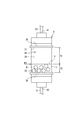
- FIG. 2 is a schematic view of the reaction vessel 9.
- the reaction vessel 9 shown in FIG. 2 is composed of a vessel that is longer in the vertical direction than in the horizontal direction.
- a large number of carriers B are provided in the reaction vessel 9.
- the carrier B is described to be larger than the actual one for the sake of easiness of explanation, and the number of the carriers B is also smaller than the actual number.
- the reaction vessel 9 may have a form other than that shown in FIG. 2, and may be a vessel that is longer in the horizontal direction than in the vertical direction.
- the intermediate pipe 8 is connected to the lower part of the reaction vessel 9.
- a pipe 23 branched from the gas pipe 17 (see FIG. 1) is connected to the upper part of the reaction vessel 9.
- an upper filter 38 is provided at the upper part, and a lower filter 39 is provided at the lower part.
- the upper filter 38 is a net-like member that allows the solution L to pass through and the carrier B cannot pass through, and is a member that covers the internal space of the reaction vessel 9 from above.
- the lower filter 39 is a net-like member that allows the solution L to pass through and the carrier B cannot pass through, and serves as a member that covers the internal space of the reaction vessel 9 from below.
- the lower surface of the upper filter 38 is defined as the upper surface 31 of the vessel, and the upper surface of the lower filter 39 is defined as the lower surface 32 of the vessel.
- the space between the upper surface 31 of the container and the lower surface 32 of the container is the reaction space 30, and a large number of carriers B are provided in the reaction space 30.
- the carrier B is not provided in the reaction space 30 in a filled state, but is provided up to the first height position P1 in the vertical direction of the reaction space 30. Therefore, in the reaction vessel 9, space Q1 is generated on the layer of the carrier B.
- FIG. 3 is an explanatory diagram showing a state in which the solution L is supplied to the reaction vessel 9 provided with the carrier B.
- the solution L is supplied from the lower side of the reaction vessel 9 through the intermediate pipe 8.
- the solution L supplied to the reaction vessel 9 is various as described above. Whichever solution L is supplied, the solution L does not fill the reaction vessel 9. That is, the solution L is not supplied until the reaction space 30 is filled, but is supplied up to the second height position P2 in the vertical direction of the reaction space 30.
- the height position P2 is a height position based on the supplied solution L and the carrier B provided in advance. Therefore, in the reaction vessel 9, space Q2 is generated on the layer (mixed layer) of the carrier B and the solution L.
- the volume of the space Q2 may be larger than the combined volume of the carrier B and the solution L.
- the height dimension H1 of the space Q2 is larger than the height dimension H2 of the layer between the carrier B and the solution L. ..
- the method of sending the solution L to the reaction vessel 9 is pressure feeding by the gas of the tank 4 (see FIG. 1), and the pressure feeding is performed by the gas supply means 20.
- the solution L sent to the reaction vessel 9 is a solution measured by the measuring mechanism 15. That is, the amount of the solution L supplied to the reaction vessel 9 is controlled, and as described above (see FIG. 3), the solution L reaches the second height position P2 in the middle of the reaction space 30 in the vertical direction. It will be in the supplied state.
- the volume of the reaction vessel 9 (reaction space 30) is set large.
- the volume of the reaction vessel 9 (reaction space 30) is such that even if the preset maximum amount of the solution L is supplied to the reaction vessel 9, the height of the liquid level of the solution L reacts. It is set large so as to be the second height position P2 in the middle in the vertical direction of the space 30. That is, in a state where the required amount of solution L is supplied to the reaction vessel 9 containing the carrier B, the volume of the reaction vessel 9 is larger than the total volume of the required amount of solution L and the carrier B. It is set.
- the upper surface 31 of the container 9 of the reaction vessel 9 is located higher than the upper surface S of the layers of the carrier B and the solution L in a state where the carrier B and the required amount of the solution L are stored.
- the upper surface 31 of the container is the lower surface of the upper filter 38.
- the volume of the reaction vessel 9 is larger than the volume of the supplied solution L.
- the volume of the reaction vessel 9 is preferably 2.5 times or more the volume (maximum required amount) of the solution L from the viewpoint of stirring efficiency, and the reaction vessel 9 is not unnecessarily increased. It is preferably 4 times or less the volume of the solution L.
- FIG. 4 is an explanatory diagram showing a state in which gas is supplied to the reaction vessel 9.
- the solution L is supplied to the reaction vessel 9 provided with the carrier B
- the solution L and the carrier B are stirred by supplying gas to the reaction vessel 9.
- the solution L measured by the measuring mechanism 15 is pushed by the gas of the tank 4 and conveyed to the reaction vessel 9 through the intermediate pipe 8 connected to the reaction vessel 9.
- this transfer is performed by the gas supply means 20.
- the gas used for transferring the solution L is supplied to the reaction vessel 9 as it is. Therefore, as shown in FIG. 4, the carrier B and the solution L can be agitated by the gas in the reaction vessel 9. That is, the gas supply means 20 is used to supply the gas for stirring the carrier B and the solution L.
- the supply of gas for stirring is continued for a predetermined time. As shown in FIGS. 3 to 4, when the solution L is supplied to the reaction vessel 9 in the required amount, the stirring state with the gas is continued thereafter.
- the solution L is not supplied to the reaction vessel 9 while the gas is being supplied to the reaction vessel 9 for stirring.
- a part of the gas supplied to the reaction vessel 9 is discharged to the outside of the reaction vessel 9 (outside the synthesizer 1) through the pipe 23.
- a plurality of carriers B may be present as a mass in the reaction vessel 9.
- the carrier B existing in the center of the mass becomes difficult to come into contact with the solution L.
- the lump is eliminated by the stirring, that is, the carrier B is dispersed in the solution L, and the carrier B in contact with the solution L increases.
- the reaction vessel 9 may have an internal filter 35.
- 5A and 5B are explanatory views showing a modified example of the reaction vessel 9.
- the internal filter 35 is composed of a net-like member that allows the solution L to pass through but does not allow the carrier B to pass through.
- the internal filter 35 is provided at a position higher than the upper surface of the layer of the carrier B in the state before the gas is supplied to the reaction vessel 9.
- the internal filter 35 is provided at a position lower than the height of the liquid level of the solution L containing the gas in a state where the gas is supplied to the reaction vessel 9.
- the carrier B Since the internal filter 35 is provided at the above position, the carrier B does not adhere to the upper surface 31 of the container. Even if the carrier B moves and adheres to the internal filter 35, it can be mixed with the solution L, and the carrier B also contributes to the production of the target product (nucleic acid). As described above, when the reaction vessel 9 has the internal filter 35, it is possible to prevent a part of the carrier B from adhering to the upper surface 31 of the vessel of the reaction vessel 9 and becoming inaccessible to the solution L. When the internal filter 35 is provided, the upper filter 38 may be omitted.
- the solution is used for a predetermined time. After the chemical reaction by L is carried out, the solution L is discharged to the outside of the reaction vessel 9.
- the means of discharge is as follows.
- the stirring in the reaction vessel 9 is stopped. Therefore, the supply of gas to the reaction vessel 9 is stopped.
- the valve 19 provided in the middle of the gas pipe 17 (see FIG. 1) is switched, and the gas in the tank 4 flows through the pipe 23 connected to the reaction vessel 9.
- the valve 25 provided in the middle of the intermediate pipe 8 is switched, and the reaction vessel 9 is connected to the discharge pipe 26.
- the gas in the tank 4 is supplied to the reaction vessel 9, and the solution L used in the reaction vessel 9 is pushed by the gas and discharged from the discharge pipe 26 to the waste liquid tank 27.
- the gas of the tank 4 is supplied to the reaction vessel 9 from above. Therefore, even if the carrier B adheres to the upper surface 31 (upper filter 38) of the container or the carrier B adheres to the internal filter 35 (see FIG. 5A), such a carrier B is used in the reaction vessel 9. It can be dropped to the bottom.
- the reaction vessel 9 has an upper port 41 and a lower port 42.
- a pipe 23 branched from the gas pipe 17 is connected to the upper port 41, and an intermediate pipe 8 is connected to the lower port 42.
- the upper port 41 serves as a gas inlet
- the lower port 42 serves as a solution L discharge port. That is, the reaction vessel 9 has an inflow port (upper port 41) at the upper part through which the gas for discharging the solution L to the outside of the reaction vessel 9 passes.
- the reaction vessel 9 has a discharge port (lower port 42) at the bottom for discharging the solution L as a waste liquid.
- the valves 19 and 25 are provided so that the lower port 42 becomes the inflow port of the solution L and the gas. Can be switched.
- the synthesizer 1 of each of the above-described embodiments includes a reaction vessel 9 and a gas supply means 20 capable of supplying gas to the reaction vessel 9.
- the reaction vessel 9 contains a large number of carriers B and is supplied with a solution L used for chemical synthesis.
- the gas supply means 20 supplies the gas to the reaction vessel 9 to stir the solution L and the carrier B.
- the carrier B is dispersed in the solution L in the reaction vessel 9, and the solution L can be brought into contact with the entire number of carriers B. As a result, the amount of the carrier B that is difficult to react is reduced as compared with the conventional case.
- the carrier B adhering to the side wall surface of the reaction vessel 9 moves to the center of the reaction vessel 9, or the carrier B that has been agglomerated disperses, so that many carriers B become the solution L. It becomes possible to make contact. As a result, it becomes possible to improve the yield of the target product (nucleic acid) obtained by chemical synthesis.
- FIG. 6 is a flow chart illustrating the synthesis method.
- Supply step S2 A step of supplying a required amount of solution L to the reaction vessel 9 containing the carrier B (see FIG. 3).
- Synthesis step S3 A step of chemically synthesizing while stirring the solution L and the carrier B by supplying gas to the reaction vessel 9 (see FIG. 4).
- the solution L is supplied to the reaction vessel 9 by pumping the gas.
- the gas supply parameters such as the pressure and the flow rate of the gas are controlled by the control device 16.
- the control is preferably performed by adjusting the supply parameters according to the type of the solution L.
- the gas supply parameter when the solution L is supplied to the reaction vessel 9 in the supply step S2 and the gas supply parameter when the gas is supplied to the reaction vessel 9 for stirring in the synthesis step S3 are the same. It may be different, but it may be different.
- the synthesis method of the present disclosure also includes the following steps.
- Measuring step S1 A step of weighing the solution L supplied to the reaction vessel 9.
- Discharge step S4 A step of discharging the solution L used for chemical synthesis in the reaction vessel 9.
- Judgment step S5 A step of determining whether or not all the synthesis is completed.
- a required amount of solution L is weighed.
- the discharge step S4 as described above, if gas is supplied from the upper part (upper port 41) of the reaction vessel 9, the used solution L is discharged as waste liquid from the lower part (lower port 42) of the reaction vessel 9. ..
- the determination step S5 if it is determined that the synthesis is incomplete, the process proceeds to the weighing step S1 and the next solution L is weighed. After that, the supply step S2, the synthesis step S3, and the discharge step S4 are repeated until all the synthesis is completed.
- the solution L is not circulated using the reaction vessel 9 as one of the flow paths, but the solution L and the carrier B are mixed in the reaction vessel 9 by the gas supplied to the reaction vessel 9. This is a method of creating a mixed flow. Therefore, it is possible to reduce the amount of the solution L used, and the chemical synthesis proceeds in a short time.
- gas is supplied to the reaction vessel 9 containing the carrier B and the solution L for stirring. Therefore, the flow of the solution L, the carrier B, and the gas occurs in the reaction vessel 9, and the volume of the contents of the reaction vessel 9 increases as compared with before the gas is supplied. Therefore, in the supply step S2 (see FIG. 3), the carrier B and the required amount of the solution L are stored in the reaction vessel 9, and in the stored state, the container upper surface 31 of the reaction vessel 9 is in a state of being stored. The position is set higher than the upper surface of the layers of the carrier B and the solution L.
- the carrier B and the required amount of solution L are stored in the lower part of the reaction vessel 9, and the space Q2 is formed in the upper part of the reaction vessel 9. Therefore, in the next synthesis step S3, when the gas is supplied to the reaction vessel 9 (see FIG. 4), the solution L and the carrier B can flow so as to escape to the space above the vessel, and the solution L and the carrier B can flow. The stirring of the carrier B is performed more actively.
- the reaction vessel 9 is filled with the carrier B and the solution L, and the reaction vessel 9 is supplied with gas for stirring from below, the pipe 23 connected to the upper part of the reaction vessel 9 can be used.
- the solution L will flow out.
- the volume of the reaction vessel 9 is set so that the upper surface 31 of the reaction vessel 9 is higher than the upper surface of the layers of the carrier B and the solution L as described above, the solution L is the upper portion. It is possible to prevent the outflow from the pipe 23 of the above.
- the solution L measured by the measuring mechanism 15, that is, the solution L outside the reaction vessel 9 is pushed by gas through the intermediate pipe 8 connected to the reaction vessel 9, and the reaction vessel 9 is pushed. Transport to.
- the gas used for conveying the solution L is supplied to the reaction vessel 9 as it is, and the carrier B is supplied by the gas.
- the solution L is stirred.
- the transfer of the solution L by the gas to the reaction vessel 9 and the stirring by the gas are performed by the gas supply means 20.
- the gas that conveys the solution L to the reaction vessel 9 is used to stir the carrier B and the solution L. If a mechanism for transporting the solution L to the reaction vessel 9 by gas is provided, it is not necessary to separately provide a gas supply mechanism for stirring, and the configuration of the synthesis apparatus 1 is simplified.
- All the gases for stirring the above are supplied from the common tank 4.
- these gases may be configured to be supplied from different tanks (gas sources).
- the gas for pumping and the gas for stirring may be supplied from different tanks (gas sources).
- the flow path for supplying the solution L to the reaction vessel 9 and the flow path for supplying the gas for stirring are common (both use the intermediate pipe 8).
- the flow path for supplying the solution L to the reaction vessel 9 and the flow path for supplying the stirring gas to the reaction vessel 9 may be different.
- the reaction vessel 9 may have a shape other than that shown in the figure.
- reaction vessel 9 gas is supplied from the lower part of the reaction vessel 9 for stirring.
- an internal pipe is provided so as to extend from the upper part of the reaction vessel 9 into the layers of the carrier B and the solution L, and gas is supplied into the layer for stirring through the internal pipe. You may. Also in this case, chemical synthesis can be carried out while stirring the solution L and the carrier B.
- Synthesis device 8 Intermediate piping (piping connected to the reaction vessel) 9: Reaction vessel 20: Gas supply means 31: Upper surface of the vessel 35: Internal filter 41: Upper port (inflow port) 42: Lower port (exhaust port) B: Carrier L: Solution
Landscapes
- Chemical & Material Sciences (AREA)
- Organic Chemistry (AREA)
- Health & Medical Sciences (AREA)
- Life Sciences & Earth Sciences (AREA)
- Engineering & Computer Science (AREA)
- Genetics & Genomics (AREA)
- Bioinformatics & Cheminformatics (AREA)
- Zoology (AREA)
- Wood Science & Technology (AREA)
- Chemical Kinetics & Catalysis (AREA)
- General Health & Medical Sciences (AREA)
- Biochemistry (AREA)
- Biomedical Technology (AREA)
- Biotechnology (AREA)
- General Engineering & Computer Science (AREA)
- Molecular Biology (AREA)
- Microbiology (AREA)
- Sustainable Development (AREA)
- Biophysics (AREA)
- Medicinal Chemistry (AREA)
- Analytical Chemistry (AREA)
- Proteomics, Peptides & Aminoacids (AREA)
- Combustion & Propulsion (AREA)
- Clinical Laboratory Science (AREA)
- Plant Pathology (AREA)
- Physics & Mathematics (AREA)
- Crystallography & Structural Chemistry (AREA)
- Physical Or Chemical Processes And Apparatus (AREA)
- Apparatus Associated With Microorganisms And Enzymes (AREA)
- Mixers With Rotating Receptacles And Mixers With Vibration Mechanisms (AREA)
- Feeding, Discharge, Calcimining, Fusing, And Gas-Generation Devices (AREA)
- Devices And Processes Conducted In The Presence Of Fluids And Solid Particles (AREA)
- Peptides Or Proteins (AREA)
Abstract
タンパク質、ペプチド、核酸等を、担体が設けられている反応容器において化学合成するための合成装置に関し、反応容器内において反応し難い担体を減少させ、化学合成により得られる目的物の収率を向上させることを目的としている。具体的には、合成装置は、多数の担体が収容されると共に溶液が供給される反応容器と、前記反応容器にガスを供給することで前記溶液及び前記担体を撹拌させるガス供給手段とを備えるように構成している。
Description
本開示の発明は、タンパク質、ペプチド、核酸等を化学合成するための合成装置及び合成方法に関する。
タンパク質、ペプチド、核酸等を化学合成する方法として、反応容器に複数種類の溶液(試薬)を順に供給し、その反応容器内において反応を進める方法がある。例えば、核酸を合成する場合、反応容器内に粒状の担体(ビーズ)を多数設け、この反応容器に、溶液を順次供給しながら、脱トリチル化、カップリング、酸化、及びキャッピングの処理を繰り返し行い、担体から塩基を次々と結合させる。
用いられる溶液は数十種類とされることもあり、これら溶液を選択的に反応容器へ送り、溶液に含まれる分子材料により目的物(核酸)が生成される。このような化学合成を行うための装置として、例えば特許文献1に記載の合成装置が知られている。
合成装置が備える反応容器には、多数の担体が収容される。その反応容器の上下一方に設けられているポートから、溶液が反応容器内に供給され、反応容器内を通過した溶液が、上下他方に設けられている別のポートから排出される。反応容器を通過させる溶液を次々と変更することにより、化学合成が進められる。
しかし、反応容器内の位置によっては反応し難い担体が存在する。すなわち、反応容器を溶液が通過しても、例えば、反応容器の側壁面付近に存在する担体に、溶液が到達しない場合がある。この場合、担体を基点とする化学合成が充分に行われない。その結果、得られる目的物(核酸)の収率が低下する可能性がある。
そこで、本開示の発明は、反応容器内において反応し難い担体を減少させ、化学合成により得られる目的物の収率を向上させることを目的とする。
本開示の合成装置は、多数の担体が収容されると共に溶液が供給される反応容器と、前記反応容器にガスを供給することで前記溶液及び前記担体を撹拌させるガス供給手段と、を備える。
前記合成装置によれば、反応容器内の場所によって反応し難い担体が減少し、化学合成により得られる目的物の収率を向上させることが可能となる。
前記合成装置によれば、反応容器内の場所によって反応し難い担体が減少し、化学合成により得られる目的物の収率を向上させることが可能となる。
従来、反応容器内に担体が満杯となって設けられていて、その反応容器に対して溶液を通過させるのが一般的である。
しかし、本開示の発明では、反応容器にガスが供給される。
そこで、好ましくは、前記反応容器は、前記担体及び必要量の前記溶液が溜められた状態で、当該担体及び当該溶液の層の上面よりも高い位置に容器上面を有する。
この構成によれば、反応容器に担体及び必要量の溶液が溜められ、反応容器の上部に空間が形成される。このため、反応容器にガスが供給された際に、溶液及び担体は容器上部の空間に逃げるようにして流れることができ、溶液及び担体の撹拌がより活発に行われる。
しかし、本開示の発明では、反応容器にガスが供給される。
そこで、好ましくは、前記反応容器は、前記担体及び必要量の前記溶液が溜められた状態で、当該担体及び当該溶液の層の上面よりも高い位置に容器上面を有する。
この構成によれば、反応容器に担体及び必要量の溶液が溜められ、反応容器の上部に空間が形成される。このため、反応容器にガスが供給された際に、溶液及び担体は容器上部の空間に逃げるようにして流れることができ、溶液及び担体の撹拌がより活発に行われる。
反応容器にガスが供給されることで担体が勢いよく移動し、担体の一部が反応容器の容器上面に付着すると、その担体は溶液と接触不能となる可能性がある。
そこで、好ましくは、前記反応容器は、当該反応容器にガスが供給される前の状態で前記担体の層の上面よりも高い位置であって、前記反応容器に供給されたガスを含む前記溶液の液面の高さよりも低い位置に、前記溶液は通過可能であり前記担体は通過不能である内部フィルタを有する。
前記のような位置に内部フィルタが設けられることで、担体は移動して内部フィルタに付着しても、溶液に混ざる。担体の一部が反応容器の容器上面に付着して溶液と接触不能となるのを防ぐことが可能となる。
そこで、好ましくは、前記反応容器は、当該反応容器にガスが供給される前の状態で前記担体の層の上面よりも高い位置であって、前記反応容器に供給されたガスを含む前記溶液の液面の高さよりも低い位置に、前記溶液は通過可能であり前記担体は通過不能である内部フィルタを有する。
前記のような位置に内部フィルタが設けられることで、担体は移動して内部フィルタに付着しても、溶液に混ざる。担体の一部が反応容器の容器上面に付着して溶液と接触不能となるのを防ぐことが可能となる。
また、好ましくは、前記ガス供給手段は、前記反応容器外の前記溶液を、当該反応容器に繋がる配管を通じて、ガスにより押して搬送し、前記ガスによる前記反応容器への前記溶液の搬送が完了すると、前記溶液を搬送するために用いた前記ガスを前記反応容器にそのまま供給して、当該ガスによって前記担体及び前記溶液を撹拌させる。
この場合、反応容器に溶液を搬送するガスが、担体及び溶液を撹拌するために用いられる。反応容器へ溶液をガスによって搬送するための機構を備えていれば、撹拌のためのガスの供給機構を別途設けなくても済む場合があり、合成装置の構成が簡素化される。
この場合、反応容器に溶液を搬送するガスが、担体及び溶液を撹拌するために用いられる。反応容器へ溶液をガスによって搬送するための機構を備えていれば、撹拌のためのガスの供給機構を別途設けなくても済む場合があり、合成装置の構成が簡素化される。
また、好ましくは、前記反応容器は、前記溶液を当該反応容器外へ排出するためのガスが通過する流入口を上部に有すると共に、前記溶液を排出する排出口を下部に有する。
この構成によれば、反応容器の上部からガスを供給すれば、反応容器の下部から使用済みの溶液が排出される。
この構成によれば、反応容器の上部からガスを供給すれば、反応容器の下部から使用済みの溶液が排出される。
また、本開示の発明は、多数の担体が収容されている反応容器に溶液を供給することで化学合成を行う合成方法であって、前記担体が収容されている前記反応容器に必要量の前記溶液を供給する供給工程と、前記反応容器にガスを供給することで前記溶液及び前記担体を撹拌しながら化学合成を行う合成工程と、を含む。
前記合成方法によれば、反応容器内の場所によって反応し難い担体が減少し、化学合成により得られる目的物の収率を向上させることが可能となる。
前記合成方法によれば、反応容器内の場所によって反応し難い担体が減少し、化学合成により得られる目的物の収率を向上させることが可能となる。
本開示の発明によれば、反応容器内において反応し難い担体を減少させ、化学合成により得られる目的物の収率を向上させることが可能となる。
〔合成装置の全体構成について〕
図1は、合成装置の一例を示す構成図である。図1に示す合成装置1は、タンパク質、ペプチド、核酸等を化学合成するための装置である。合成装置1は、反応容器9を備える。反応容器9に複数種類の溶液(試薬)Lが順に供給され、その反応容器9内において化学合成が進められる。核酸を合成する場合、反応容器9内に粒状である担体Bが多数設けられる。担体Bはビーズとも呼ばれ、例えば、ガラス製やポリマー製である。反応容器9に溶液Lを順次供給しながら、脱トリチル化、カップリング、酸化、及びキャッピングの処理が繰り返し行われ、担体Bから塩基(分子材料)が次々と結合される。用いられる溶液Lは数十種類とされ、これら溶液Lが選択的に反応容器9へ送られ、溶液Lに含まれる分子材料により目的物(核酸)が生成される。
図1は、合成装置の一例を示す構成図である。図1に示す合成装置1は、タンパク質、ペプチド、核酸等を化学合成するための装置である。合成装置1は、反応容器9を備える。反応容器9に複数種類の溶液(試薬)Lが順に供給され、その反応容器9内において化学合成が進められる。核酸を合成する場合、反応容器9内に粒状である担体Bが多数設けられる。担体Bはビーズとも呼ばれ、例えば、ガラス製やポリマー製である。反応容器9に溶液Lを順次供給しながら、脱トリチル化、カップリング、酸化、及びキャッピングの処理が繰り返し行われ、担体Bから塩基(分子材料)が次々と結合される。用いられる溶液Lは数十種類とされ、これら溶液Lが選択的に反応容器9へ送られ、溶液Lに含まれる分子材料により目的物(核酸)が生成される。
合成装置1は、用いられる溶液Lと同数の収容容器(試薬瓶)2を設ける領域を備える。収容容器2それぞれに各溶液Lが溜められている。なお、図1では、三つの収容容器2のみが示されていて、その他の収容容器2については図示省略している。各収容容器2は、密閉容器であり、導入管5及び導出管6が繋がっている。
合成装置1は、ガスを溜めているタンク4、前記導入管5、前記導出管6、中間容器7、中間配管8、反応容器9、計量機構15、及び制御装置16を備える。タンク4には大気よりも高圧のガスが充填されていて、本開示の合成装置1では、不活性ガスとしてアルゴンガスが充填されている。なお、本実施形態では、アルゴンガスを使用しているが、不活性ガスであって、脱水されたガスであれば他のガスでもよい。このガスは、後に説明するが、収容容器2の溶液Lを反応容器9へ搬送するために用いられる他に、反応容器9で担体B及び溶液Lを撹拌するために用いられる。
複数の収容容器2と同数の導入管5は、共通する上流側配管10から分岐した配管である。その上流側配管10にレギュレータ11及びバルブ12が設けられている。上流側配管10は、タンク4と接続されていて、タンク4のガスが各収容容器2に供給され、レギュレータ11により各収容容器2の内圧が調整される。ガスにより各収容容器2の内圧が高まり、収容容器2の溶液Lは導出管6から送り出される。つまり、各収容容器2と中間容器7との差圧で各収容容器2の溶液Lが導出管6を通じて中間容器7へ圧送される。
導出管6それぞれにはバルブ14が設けられている。開状態とするバルブ14が選択されることで、複数の収容容器2の溶液Lの中から所定の溶液Lが選択的に導出管6を通じて中間容器7へ送られる。開状態とするバルブ14の選択は制御装置16によって行われる。
中間容器7は、各溶液Lを計量するための容器となる。中間容器7は、各溶液Lを溜めることができる有底筒状の容器である。中間容器7の入口領域(開口部7a)に複数の導出管6が集約して設けられている。このため、選択的に導出管6を通じて送られた溶液Lが中間容器7に導入され、この中間容器7に溜められる。
計量機構15は、中間容器7に溜められる溶液Lを計量する。計量機構15では、中間容器7を計量容器として機能させる。計量機構15は、例えばロードセル等による測定器を有し、中間容器7に溜められる溶液Lを計量する。計量機構15による計量結果は、制御装置16に送信される。制御装置16は、計量結果に基づいてバルブ14の開閉動作制御を行い、規定量の溶液Lを中間容器7において取得する。その規定量の溶液Lが中間配管8を通じて反応容器9へ送られる。中間配管8には、バルブ21が設けられており、計量を行う際、バルブ21は閉状態にある。
中間容器7から反応容器9への溶液Lの供給方式は、ガスによる圧送であり、タンク4のガスが用いられる。その圧送の際、バルブ21は開状態となる。その圧送のために、合成装置1は、中間容器7を収容する密閉容器29を備える。密閉容器29とタンク4との間にはガス用の配管17が設けられている。このガス用の配管17に、第二のレギュレータ18及びバルブ19が設けられている。図1に示すバルブ19は三方向バルブであるが、別の形式であってもよい。
中間容器7は、密閉容器29内で開口していて、タンク4のガスが密閉容器29に供給されると、密閉容器29内のガスの圧力(内圧)が中間容器7に溜められている溶液Lに作用し、密閉容器29(中間容器7)と反応容器9との差圧で中間容器7の溶液Lが中間配管8を通じて反応容器9へ圧送される。このように、本開示の合成装置1では、中間容器7の溶液Lを反応容器9へ送る送液の方式は、ガスによる圧送方式であり、その圧送はガス供給手段20により行われる。図1に示す形態の場合、そのガス供給手段20には、タンク4、ガス用の配管17、密閉容器29、中間配管8が含まれる。なお、ガス供給手段20の構成は、他であってもよい。
以上より、複数の収容容器2の内の少なくとも一つから溶液Lが選択的に中間容器7へ送られ、その中間容器7で計量が行われると、その溶液Lは反応容器9へ送られる。その溶液Lは、反応容器9で化学合成に用いられる。その後、溶液Lは排出管26を通じて廃液タンク27へ排出される。
このような反応容器9への溶液Lの供給が、溶液Lの種類を変更しながら繰り返し行われ、複数種類の溶液Lが反応容器9に順に供給され、反応容器9内において化学合成が進められる。反応容器9には多数の担体Bが設けられており、担体Bから塩基を次々と結合させ、核酸が合成される。
このような反応容器9への溶液Lの供給が、溶液Lの種類を変更しながら繰り返し行われ、複数種類の溶液Lが反応容器9に順に供給され、反応容器9内において化学合成が進められる。反応容器9には多数の担体Bが設けられており、担体Bから塩基を次々と結合させ、核酸が合成される。
〔反応容器9について〕
図2は、反応容器9の概略図である。図2に示す反応容器9は、水平方向よりも鉛直方向に長い容器により構成されている。反応容器9内に多数の担体Bが設けられている。なお、図2等では、説明を容易とするために担体Bは実際よりも大きく記載されていて、また、その数も実際よりも少なく記載されている。反応容器9は、図2に示す形態以外であってもよく、鉛直方向よりも水平方向に長い容器であってもよい。
図2は、反応容器9の概略図である。図2に示す反応容器9は、水平方向よりも鉛直方向に長い容器により構成されている。反応容器9内に多数の担体Bが設けられている。なお、図2等では、説明を容易とするために担体Bは実際よりも大きく記載されていて、また、その数も実際よりも少なく記載されている。反応容器9は、図2に示す形態以外であってもよく、鉛直方向よりも水平方向に長い容器であってもよい。
反応容器9の下部に中間配管8が接続されている。反応容器9の上部に、ガス用の配管17(図1参照)から分岐した配管23が接続されている。反応容器9内には、上部に上フィルタ38が設けられていて、下部に下フィルタ39が設けられている。上フィルタ38は、溶液Lを通過可能とし担体Bを通過不能とする網状の部材であり、反応容器9の内部空間を上から蓋をする部材となる。下フィルタ39は、溶液Lを通過可能とし担体Bを通過不能とする網状の部材であり、反応容器9の内部空間を下から蓋をする部材となる。本開示の反応容器9では、上フィルタ38の下面が容器上面31と定義され、下フィルタ39の上面が容器下面32と定義される。容器上面31と容器下面32との間の空間が反応空間30であり、その反応空間30に担体Bが多数設けられている。
図2に示すように、担体Bは、反応空間30に充満状態となって設けられるのではなく、反応空間30の鉛直方向について途中の第一の高さ位置P1まで設けられる。このため、反応容器9内では、担体Bの層の上に、空間Q1が生じる。
図3は、担体Bが設けられている反応容器9に、溶液Lが供給された状態を示す説明図である。溶液Lは、中間配管8を通じて反応容器9の下部側から供給される。反応容器9に供給される溶液Lは、前記のとおり様々である。いずれの溶液Lが供給された場合であっても、その溶液Lは反応容器9に充満状態とならない。つまり、溶液Lは、反応空間30に充満状態となるまで供給されるのではなく、反応空間30の鉛直方向について途中の第二の高さ位置P2まで供給される。なお、その高さ位置P2は、供給された溶液Lと予め設けられている担体Bとに基づく高さ位置である。このため、反応容器9内では、担体Bと溶液Lとの層(混合層)の上に、空間Q2が生じる。
反応空間30のうち、前記空間Q2の容積は、担体Bと溶液Lとをあわせた容積よりも大きくてもよい。本開示の反応容器9では、反応空間30の横断面は鉛直方向に一定であるため、前記空間Q2の高さ寸法H1は、担体Bと溶液Lとの層の高さ寸法H2よりも大きくなる。
ここで、反応容器9への溶液Lの供給方法について再び説明する。前記のとおり、反応容器9へ溶液Lを送る方式は、タンク4(図1参照)のガスによる圧送であり、その圧送は、前記ガス供給手段20により行われる。反応容器9へ送られる溶液Lは、計量機構15によって計量された溶液である。つまり、反応容器9へ供給される溶液Lは、量が管理されていて、前記のとおり(図3参照)、溶液Lは、反応空間30の鉛直方向について途中の第二の高さ位置P2まで供給された状態となる。
そのために、反応容器9(反応空間30)の容積は大きく設定されている。具体的に説明すると、反応容器9(反応空間30)の容積は、予め設定されている最大量の溶液Lがその反応容器9に供給されても、その溶液Lの液面の高さが反応空間30の鉛直方向について途中の第二の高さ位置P2となるように、大きく設定されている。つまり、担体Bが収容されている反応容器9に、必要量の溶液Lが供給された状態で、反応容器9の容積は、前記必要量の溶液Lと担体Bとの合計の容積よりも大きく設定されている。更に言い換えると、反応容器9が有する容器上面31は、担体B及び必要量の溶液Lが溜められた状態で、これら担体B及び溶液Lの層の上面Sよりも高い位置にある。本開示の合成装置1では、前記のとおり、容器上面31は上フィルタ38の下面である。
反応容器9の容積は、供給される溶液Lの容積に比べて大きい。例えば、反応容器9の容積は、撹拌の効率の観点で、溶液Lの容積(最大必要量)の2.5倍以上であるのが好ましく、また、反応容器9を不要に大きくしないために、溶液Lの容積の4倍以下であるのが好ましい。
図4は、反応容器9にガスを供給している状態を示す説明図である。担体Bが設けられている反応容器9に溶液Lが供給されると、その反応容器9に対して、ガスを供給することで溶液L及び担体Bを撹拌させる。特に、本開示の合成装置1では(図1参照)、計量機構15によって計量された溶液Lは、反応容器9に繋がる中間配管8を通じて、タンク4のガスにより押されて反応容器9へ搬送される。この搬送は、前記のとおり、ガス供給手段20により行われる。そのガスによる反応容器9への溶液Lの搬送が完了すると、その溶液Lを搬送するために用いた前記ガスが反応容器9にそのまま供給される。このため、図4に示すように、反応容器9内において、そのガスによって担体B及び溶液Lを撹拌することができる。つまり、担体B及び溶液Lを撹拌するためのガスの供給が、前記ガス供給手段20により行われる。
撹拌のためのガスの供給は、所定時間について継続される。図3から図4に示すように、溶液Lが必要量について反応容器9に供給されると、その後、ガスによる撹拌状態が継続される。本開示の合成装置1の場合、撹拌のためにガスを反応容器9に供給している間、その反応容器9に溶液Lは供給されない。反応容器9に供給されたガスの一部は、配管23を通じて反応容器9の外部(合成装置1の外部)に排出される。
前記のとおり(図3参照)反応容器9内では、担体Bと溶液Lとの層(混合層)の上に、空間Q2が生じる。このため、撹拌のために反応容器9にガスが追加されても、ガスを含む溶液L及び担体Bは、容器上面31にまで到達しない(到達し難い)。つまり、図4に示すように、反応容器9にガスが供給されても、反応空間30において、容器上部の空間Q3が生じ、溶液L及び担体Bはその容器上部の空間Q3に逃げるようにして流れることができる。このため、ガスによる担体B及び溶液Lの撹拌が活発に行われる。
ガスの供給により、反応容器9内において、そのガスを含む溶液Lと担体Bとの混流が生じる。その混流の上面の高さよりも、容器上面31は高い位置にある。
ガスの供給により、反応容器9内において、そのガスを含む溶液Lと担体Bとの混流が生じる。その混流の上面の高さよりも、容器上面31は高い位置にある。
反応容器9内で、複数の担体Bが塊となって存在していることがある。この場合、その塊の中央に存在する担体Bは、溶液Lと触れにくくなる。しかし、本開示の発明では、前記撹拌により塊が解消され、つまり、担体Bは溶液Lに分散し、溶液Lと触れる担体Bは増加する。
ここで、反応容器9の変形例について説明する。
前記のとおり(図4参照)、撹拌のために反応容器9にガスが供給されても、ガスを含む溶液L及び担体Bは、容器上面31にまで到達しない(到達し難い)。しかし、反応容器9にガスが供給されることで担体Bが勢いよく移動し、担体Bの一部が容器上面31に付着する可能性がある。すると、その担体Bは溶液Lと接触不能となり、目的物(核酸)の生成に寄与しない可能性がある。
前記のとおり(図4参照)、撹拌のために反応容器9にガスが供給されても、ガスを含む溶液L及び担体Bは、容器上面31にまで到達しない(到達し難い)。しかし、反応容器9にガスが供給されることで担体Bが勢いよく移動し、担体Bの一部が容器上面31に付着する可能性がある。すると、その担体Bは溶液Lと接触不能となり、目的物(核酸)の生成に寄与しない可能性がある。
そこで、図5A及び図5Bに示すように、反応容器9は、内部フィルタ35を有していてもよい。図5A及び図5Bは、反応容器9の変形例を示す説明図である。内部フィルタ35は、上フィルタ38及び下フィルタ39と同様、溶液Lは通過可能であるが、担体Bは通過不能である網状の部材により構成される。その内部フィルタ35は、図5Aに示すように、反応容器9にガスが供給される前の状態では、担体Bの層の上面よりも高い位置に設けられる。更に、図5Bに示すように、反応容器9にガスが供給された状態で、そのガスを含む溶液Lの液面の高さよりも低い位置に、内部フィルタ35は設けられる。
前記の位置に内部フィルタ35が設けられるため、担体Bは、容器上面31に付着することはない。なお、担体Bが移動して内部フィルタ35に付着しても、溶液Lに混ざることができ、その担体Bについても目的物(核酸)の生成に寄与する。このように、反応容器9が内部フィルタ35を有する場合、担体Bの一部が反応容器9の容器上面31に付着して、溶液Lと接触不能となるのを防ぐことが可能となる。なお、内部フィルタ35が設けられる場合、上フィルタ38は省略されていてもよい。
図2、図3、図4に示す反応容器9(第一の形態)であっても、図5A及び図5Bに示す反応容器9(第二の形態)であっても、所定時間について、溶液Lによる化学反応が進められた後、その溶液Lは反応容器9外へ排出される。その排出の手段は、次のようにして行われる。
まず、反応容器9における前記撹拌を停止する。そのために、反応容器9へのガスの供給を停止する。ガス用の配管17(図1参照)の途中に設けられているバルブ19を切り替え、タンク4のガスを反応容器9に繋がる配管23に流す。そのバルブ19の切り替えにあわせて、中間配管8の途中に設けられているバルブ25を切り替え、反応容器9を排出管26と繋げる。これにより、タンク4のガスは反応容器9に供給され、反応容器9で使用済みとなった溶液Lは、そのガスに押されて排出管26から廃液タンク27に排出される。
反応容器9の溶液Lを排出するために、タンク4のガスが反応容器9に、その上部から供給される。このため、容器上面31(上フィルタ38)に担体Bが付着していたり、内部フィルタ35(図5A参照)に担体Bが付着していたりしても、そのような担体Bを反応容器9の下部に落下させることが可能となる。
図1に示すように、反応容器9は上のポート41及び下のポート42を有する。上のポート41にガス用の配管17から分岐した配管23が接続されていて、下のポート42に中間配管8が接続されている。反応容器9から溶液Lを排出する際には、上のポート41がガスの流入口となり、下のポート42が溶液Lの排出口となる。つまり、反応容器9は、溶液Lをその反応容器9外へ排出するためのガスが通過する流入口(上ポート41)を上部に有する。反応容器9は、溶液Lを廃液として排出する排出口(下ポート42)を下部に有する。なお、反応容器9に対して、溶液Lを供給する際及び撹拌のためにガスを供給する際には、下のポート42が溶液L及びガスの流入口となるように、バルブ19,25が切り替えられる。
〔本開示の合成装置1について〕
以上のように、前記各形態の合成装置1は、反応容器9と、その反応容器9にガスを供給することが可能であるガス供給手段20とを備える。反応容器9には、多数の担体Bが収容されると共に、化学合成に用いられる溶液Lが供給される。ガス供給手段20は、反応容器9内での化学合成の際に、その反応容器9にガスを供給することで、溶液L及び担体Bを撹拌させる。この合成装置1によれば、反応容器9内において担体Bが溶液L中で分散され、多数の担体Bの全体に溶液Lを接触させることが可能となる。その結果、従来と比較して、反応し難い担体Bが減少する。例えば、反応容器9の側壁面に付着していた担体Bが、反応容器9の中央に移動したり、塊となっていた担体Bがばらけたりすることで、多くの担体Bが溶液Lと接触することが可能となる。この結果、化学合成により得られる目的物(核酸)の収率を向上させることが可能となる。
以上のように、前記各形態の合成装置1は、反応容器9と、その反応容器9にガスを供給することが可能であるガス供給手段20とを備える。反応容器9には、多数の担体Bが収容されると共に、化学合成に用いられる溶液Lが供給される。ガス供給手段20は、反応容器9内での化学合成の際に、その反応容器9にガスを供給することで、溶液L及び担体Bを撹拌させる。この合成装置1によれば、反応容器9内において担体Bが溶液L中で分散され、多数の担体Bの全体に溶液Lを接触させることが可能となる。その結果、従来と比較して、反応し難い担体Bが減少する。例えば、反応容器9の側壁面に付着していた担体Bが、反応容器9の中央に移動したり、塊となっていた担体Bがばらけたりすることで、多くの担体Bが溶液Lと接触することが可能となる。この結果、化学合成により得られる目的物(核酸)の収率を向上させることが可能となる。
そして、前記各形態の合成装置1により行われる合成方法、つまり、多数の担体Bが収容されている反応容器9に溶液Lを供給することにより化学合成を行う合成方法は、次の工程を含む。なお、図6は、合成方法を説明するフロー図である。
供給工程S2:担体Bが収容された反応容器9に必要量の溶液Lを供給する工程(図3参照)。
合成工程S3:反応容器9にガスを供給することで溶液L及び担体Bを撹拌しながら化学合成を行う工程(図4参照)。
供給工程S2:担体Bが収容された反応容器9に必要量の溶液Lを供給する工程(図3参照)。
合成工程S3:反応容器9にガスを供給することで溶液L及び担体Bを撹拌しながら化学合成を行う工程(図4参照)。
本開示の合成装置1の場合、供給工程S2では、ガスの圧送により溶液Lは反応容器9に供給される。
合成工程S3では、反応容器9にガスを供給する際、そのガスの圧力及び流量等のガスの供給パラメータが制御装置16によって制御される。その制御は、溶液Lの種類に応じて供給パラメータが調整されて行われるのが好ましい。供給工程S2において溶液Lを反応容器9に供給する際のガスの供給パラメータと、合成工程S3において撹拌のために反応容器9にガスを供給する際のそのガスの供給パラメータとは、同じであってもよいが、異なっていてもよい。
合成工程S3では、反応容器9にガスを供給する際、そのガスの圧力及び流量等のガスの供給パラメータが制御装置16によって制御される。その制御は、溶液Lの種類に応じて供給パラメータが調整されて行われるのが好ましい。供給工程S2において溶液Lを反応容器9に供給する際のガスの供給パラメータと、合成工程S3において撹拌のために反応容器9にガスを供給する際のそのガスの供給パラメータとは、同じであってもよいが、異なっていてもよい。
更に、本開示の合成方法(図6参照)には、次の工程も含まれる。
計量工程S1:反応容器9へ供給する溶液Lの計量を行う工程。
排出工程S4:反応容器9で化学合成のために使用された溶液Lを排出する工程。
判定工程S5:合成が全て完了したかを判定する工程。
計量工程S1:反応容器9へ供給する溶液Lの計量を行う工程。
排出工程S4:反応容器9で化学合成のために使用された溶液Lを排出する工程。
判定工程S5:合成が全て完了したかを判定する工程。
計量工程S1では、必要量の溶液Lが計量される。排出工程S4では、前記のとおり、反応容器9の上部(上のポート41)からガスを供給すれば、反応容器9の下部(下のポート42)から使用済みの溶液Lが廃液として排出される。
判定工程S5では、合成が未完了であると判定された場合、計量工程S1に進み、次の溶液Lの計量が行われる。その後、供給工程S2、合成工程S3、排出工程S4が、合成が全て完了するまで繰り返し行われる。
判定工程S5では、合成が未完了であると判定された場合、計量工程S1に進み、次の溶液Lの計量が行われる。その後、供給工程S2、合成工程S3、排出工程S4が、合成が全て完了するまで繰り返し行われる。
本開示の合成方法では、反応容器9を流路の一つとして用いて溶液Lを循環させる方法ではなく、反応容器9に供給するガスによって、その反応容器9内で溶液Lと担体Bとの混流を生じさせる方法である。このため、溶液Lの使用量を低減することが可能であり、また、短時間で化学合成が進む。
本開示の合成方法では、撹拌のために、担体B及び溶液Lを含む反応容器9にガスが供給される。このため、反応容器9内で溶液L、担体B及びガスの流れが生じ、ガスの供給前と比べて、反応容器9の内容物の容積が増加する。
そこで、供給工程S2では(図3参照)、反応容器9に担体B及び必要量の溶液Lが溜められた状態となるが、その溜められた状態で、反応容器9の容器上面31は、これら担体B及び溶液Lの層の上面よりも高い位置となるように設定されている。
これにより、反応容器9の下部に担体B及び必要量の溶液Lが溜められ、反応容器9の上部に空間Q2が形成される。このため、次の合成工程S3において、反応容器9にガスが供給された際に(図4参照)、溶液L及び担体Bは容器上部の空間に逃げるようにして流れることができ、溶液L及び担体Bの撹拌がより活発に行われる。
そこで、供給工程S2では(図3参照)、反応容器9に担体B及び必要量の溶液Lが溜められた状態となるが、その溜められた状態で、反応容器9の容器上面31は、これら担体B及び溶液Lの層の上面よりも高い位置となるように設定されている。
これにより、反応容器9の下部に担体B及び必要量の溶液Lが溜められ、反応容器9の上部に空間Q2が形成される。このため、次の合成工程S3において、反応容器9にガスが供給された際に(図4参照)、溶液L及び担体Bは容器上部の空間に逃げるようにして流れることができ、溶液L及び担体Bの撹拌がより活発に行われる。
なお、仮に、反応容器9が担体Bと溶液Lとによって充満状態にある場合、その反応容器9に撹拌のためにガスが下から供給されると、反応容器9の上部に繋がる配管23から、溶液Lは流出してしまう。しかし、前記のように反応容器9の容器上面31が、担体B及び溶液Lの層の上面よりも高い位置となるように、反応容器9の容積が設定されていることで、溶液Lが上部の配管23から流出するのを防ぐことができる。
また、本開示の合成方法の場合、供給工程S2では、計量機構15において計量した溶液L、つまり、反応容器9外の溶液Lを、反応容器9に繋がる中間配管8を通じてガスにより押して反応容器9へ搬送する。そして、前記ガスによる反応容器9への溶液Lの搬送が完了すると、合成工程S3では、その溶液Lを搬送するために用いた前記ガスを反応容器9にそのまま供給して、当該ガスによって担体B及び溶液Lを撹拌させる。このような反応容器9へのガスによる溶液Lの搬送及びそのガスによる撹拌は、前記ガス供給手段20によって行われる。以上のように、反応容器9に溶液Lを搬送するガスが、担体B及び溶液Lを撹拌するために用いられる。反応容器9へ溶液Lをガスによって搬送するための機構を備えていれば、撹拌のためのガスの供給機構を別途設けなくても済み、合成装置1の構成が簡素化される。
〔その他について〕
前記の合成装置1では、収容容器2から計量機構15へ溶液Lを圧送するためのガス、計量機構15から反応容器9へ溶液Lを圧送するガス、及び、反応容器9において担体B及び溶液Lを撹拌するためのガスは、全て、共通するタンク4から供給されている。しかし、図示しないが、これらガスはそれぞれ別のタンク(ガス源)から供給されるように構成されていてもよい。例えば、前記圧送のためのガスと、撹拌用のガスとは、別のタンク(ガス源)から供給されてもよい。また、前記の合成装置1では、反応容器9に溶液Lを供給するための流路と、撹拌用のガスを供給するための流路とが、共通であるが(いずれも中間配管8を用いているが)、反応容器9に溶液Lを供給するための流路と、撹拌用のガスを反応容器9へ供給するための流路とは別の流路であってもよい。また、反応容器9について、図示した形状以外であってもよい。
前記の合成装置1では、収容容器2から計量機構15へ溶液Lを圧送するためのガス、計量機構15から反応容器9へ溶液Lを圧送するガス、及び、反応容器9において担体B及び溶液Lを撹拌するためのガスは、全て、共通するタンク4から供給されている。しかし、図示しないが、これらガスはそれぞれ別のタンク(ガス源)から供給されるように構成されていてもよい。例えば、前記圧送のためのガスと、撹拌用のガスとは、別のタンク(ガス源)から供給されてもよい。また、前記の合成装置1では、反応容器9に溶液Lを供給するための流路と、撹拌用のガスを供給するための流路とが、共通であるが(いずれも中間配管8を用いているが)、反応容器9に溶液Lを供給するための流路と、撹拌用のガスを反応容器9へ供給するための流路とは別の流路であってもよい。また、反応容器9について、図示した形状以外であってもよい。
前記の開示では、反応容器9において、撹拌のためにガスを反応容器9の下部から供給している。しかし、図示しないが、反応容器9の上部から、担体B及び溶液Lの層の中にまで延びるように内部配管が設けられ、その内部配管を通じて撹拌のためにガスを、当該層の中に供給してもよい。この場合においても、溶液L及び担体Bを撹拌しながら化学合成を行うことができる。
今回開示した実施形態は全ての点で例示であって制限的なものではない。本発明の技術的範囲は前述の実施形態に限定されるものではなく、この技術的範囲には特許請求の範囲に記載された構成と均等の範囲内での全ての変更が含まれる。
1:合成装置 8:中間配管(反応容器に繋がる配管)
9:反応容器 20:ガス供給手段
31:容器上面 35:内部フィルタ
41:上のポート(流入口) 42:下のポート(排出口)
B:担体 L:溶液
9:反応容器 20:ガス供給手段
31:容器上面 35:内部フィルタ
41:上のポート(流入口) 42:下のポート(排出口)
B:担体 L:溶液
Claims (6)
- 多数の担体が収容されると共に溶液が供給される反応容器と、
前記反応容器にガスを供給することで前記溶液及び前記担体を撹拌させるガス供給手段と、
を備える、合成装置。 - 前記反応容器は、前記担体及び必要量の前記溶液が溜められた状態で、当該担体及び当該溶液の層の上面よりも高い位置に容器上面を有する、請求項1に記載の合成装置。
- 前記反応容器は、
当該反応容器にガスが供給される前の状態で前記担体の層の上面よりも高い位置であって、前記反応容器に供給されたガスを含む前記溶液の液面の高さよりも低い位置に、前記溶液は通過可能であり前記担体は通過不能である内部フィルタを有する、請求項1又は2に記載の合成装置。 - 前記ガス供給手段は、
前記反応容器外の前記溶液を、当該反応容器に繋がる配管を通じて、ガスにより押して搬送し、
前記ガスによる前記反応容器への前記溶液の搬送が完了すると、前記溶液を搬送するために用いた前記ガスを前記反応容器にそのまま供給して、当該ガスによって前記担体及び前記溶液を撹拌させる、
請求項1~3のいずれか一項に記載の合成装置。 - 前記反応容器は、前記溶液を当該反応容器外へ排出するためのガスが通過する流入口を上部に有すると共に、前記溶液を排出する排出口を下部に有する、
請求項1~4のいずれか一項に記載の合成装置。 - 多数の担体が収容されている反応容器に溶液を供給することで化学合成を行う合成方法であって、
前記担体が収容されている前記反応容器に必要量の前記溶液を供給する供給工程と、
前記反応容器にガスを供給することで前記溶液及び前記担体を撹拌しながら化学合成を行う合成工程と、
を含む合成方法。
Priority Applications (3)
| Application Number | Priority Date | Filing Date | Title |
|---|---|---|---|
| CN202080077878.9A CN114650998A (zh) | 2019-12-18 | 2020-09-14 | 合成装置及合成方法 |
| EP20903555.9A EP4079397A4 (en) | 2019-12-18 | 2020-09-14 | SYNTHESIS DEVICE AND SYNTHESIS METHOD |
| US17/786,316 US20230024632A1 (en) | 2019-12-18 | 2020-09-14 | Synthesis device and synthesis method |
Applications Claiming Priority (2)
| Application Number | Priority Date | Filing Date | Title |
|---|---|---|---|
| JP2019-228421 | 2019-12-18 | ||
| JP2019228421A JP2021094533A (ja) | 2019-12-18 | 2019-12-18 | 合成装置及び合成方法 |
Publications (1)
| Publication Number | Publication Date |
|---|---|
| WO2021124627A1 true WO2021124627A1 (ja) | 2021-06-24 |
Family
ID=76430322
Family Applications (1)
| Application Number | Title | Priority Date | Filing Date |
|---|---|---|---|
| PCT/JP2020/034738 Ceased WO2021124627A1 (ja) | 2019-12-18 | 2020-09-14 | 合成装置及び合成方法 |
Country Status (5)
| Country | Link |
|---|---|
| US (1) | US20230024632A1 (ja) |
| EP (1) | EP4079397A4 (ja) |
| JP (1) | JP2021094533A (ja) |
| CN (1) | CN114650998A (ja) |
| WO (1) | WO2021124627A1 (ja) |
Cited By (1)
| Publication number | Priority date | Publication date | Assignee | Title |
|---|---|---|---|---|
| WO2022202191A1 (ja) * | 2021-03-24 | 2022-09-29 | 東レエンジニアリング株式会社 | 薬液合成装置 |
Families Citing this family (1)
| Publication number | Priority date | Publication date | Assignee | Title |
|---|---|---|---|---|
| JP2023146117A (ja) * | 2022-03-29 | 2023-10-12 | 東レエンジニアリング株式会社 | 薬液合成方法及び薬液合成装置 |
Citations (8)
| Publication number | Priority date | Publication date | Assignee | Title |
|---|---|---|---|---|
| JPS54117379A (en) * | 1978-03-06 | 1979-09-12 | Tokyo Rikakikai Kk | Contacting reactor |
| JPS60137288A (ja) * | 1983-12-27 | 1985-07-20 | Chiyoda Chem Eng & Constr Co Ltd | 生物反応方法 |
| US4983517A (en) * | 1986-08-22 | 1991-01-08 | Battelle Memorial Institute | Reacting materials |
| JPH09505484A (ja) * | 1994-04-21 | 1997-06-03 | ジェネティック セラピー インコーポレイテッド | バイオリアクタ |
| JP2001340075A (ja) * | 2000-05-31 | 2001-12-11 | Nisshinbo Ind Inc | バイオリアクター用担体、その製造方法及び該担体の使用方法 |
| JP2006061097A (ja) * | 2004-08-27 | 2006-03-09 | Hitachi Plant Eng & Constr Co Ltd | 固定化微生物の製造方法、及びそれによって製造された固定化微生物、並びにその固定化微生物を用いた反応装置 |
| WO2016117023A1 (ja) * | 2015-01-20 | 2016-07-28 | 三菱化学エンジニアリング株式会社 | 酸素含有気体のマイクロナノバブルを供給する装置及び溶存二酸化炭素を除去する装置を備えた生物反応装置及びこの生物反応装置を用いた生物反応方法 |
| JP2019170187A (ja) | 2018-03-27 | 2019-10-10 | 東レエンジニアリング株式会社 | 合成装置 |
Family Cites Families (17)
| Publication number | Priority date | Publication date | Assignee | Title |
|---|---|---|---|---|
| JPS60105692A (ja) * | 1983-11-14 | 1985-06-11 | Nippon Zeon Co Ltd | ポリヌクレオチド合成装置 |
| US4668476A (en) * | 1984-03-23 | 1987-05-26 | Applied Biosystems, Inc. | Automated polypeptide synthesis apparatus |
| JPS6379898A (ja) * | 1986-09-22 | 1988-04-09 | Nippon Zeon Co Ltd | ポリヌクレオチド合成反応における脱保護基反応の制御方法 |
| US5252296A (en) * | 1990-05-15 | 1993-10-12 | Chiron Corporation | Method and apparatus for biopolymer synthesis |
| US5880311A (en) * | 1994-07-22 | 1999-03-09 | Tonen Corporation | Method of contacting catalyst particles with gas and liquid |
| JP4415414B2 (ja) * | 1998-09-25 | 2010-02-17 | 株式会社島津製作所 | 自動合成装置 |
| JP2001129575A (ja) * | 1999-11-04 | 2001-05-15 | Mitamura Setsubi Sekkei Jimusho:Kk | 汚水処理用微生物培養装置 |
| US6649051B1 (en) * | 2002-05-01 | 2003-11-18 | Biotage, Inc. | Processing of chemicals in flow-through device with porous media |
| US20060014176A1 (en) * | 2004-05-26 | 2006-01-19 | Iyer Radhakrishnan P | Reactor for chemical synthesis |
| CA2825572C (en) * | 2012-09-04 | 2021-01-12 | Jason International, Inc. | Microbubble therapy method and generating apparatus |
| EP2742994A1 (en) * | 2012-12-14 | 2014-06-18 | Emerging Fuels Technology Inc. | Three phase horizontal reactor |
| JP2018176021A (ja) * | 2017-04-05 | 2018-11-15 | 日立Geニュークリア・エナジー株式会社 | 容器内析出物処理システム |
| CN206631567U (zh) * | 2017-04-14 | 2017-11-14 | 青岛科技大学 | 一种反应时间可控的气固两相反应器 |
| JP6405483B1 (ja) * | 2018-04-02 | 2018-10-17 | マイクロ波化学株式会社 | 処理装置 |
| CN206980628U (zh) * | 2017-06-30 | 2018-02-09 | 江苏省冶金设计院有限公司 | 一种制备液体粘结剂的系统 |
| JP2019034290A (ja) * | 2017-08-21 | 2019-03-07 | 東レエンジニアリング株式会社 | 合成装置 |
| CN210506367U (zh) * | 2019-05-08 | 2020-05-12 | 南京安佰思生物科技有限公司 | 一种固定化酶的新型反应装置 |
-
2019
- 2019-12-18 JP JP2019228421A patent/JP2021094533A/ja active Pending
-
2020
- 2020-09-14 CN CN202080077878.9A patent/CN114650998A/zh active Pending
- 2020-09-14 WO PCT/JP2020/034738 patent/WO2021124627A1/ja not_active Ceased
- 2020-09-14 EP EP20903555.9A patent/EP4079397A4/en not_active Withdrawn
- 2020-09-14 US US17/786,316 patent/US20230024632A1/en not_active Abandoned
Patent Citations (8)
| Publication number | Priority date | Publication date | Assignee | Title |
|---|---|---|---|---|
| JPS54117379A (en) * | 1978-03-06 | 1979-09-12 | Tokyo Rikakikai Kk | Contacting reactor |
| JPS60137288A (ja) * | 1983-12-27 | 1985-07-20 | Chiyoda Chem Eng & Constr Co Ltd | 生物反応方法 |
| US4983517A (en) * | 1986-08-22 | 1991-01-08 | Battelle Memorial Institute | Reacting materials |
| JPH09505484A (ja) * | 1994-04-21 | 1997-06-03 | ジェネティック セラピー インコーポレイテッド | バイオリアクタ |
| JP2001340075A (ja) * | 2000-05-31 | 2001-12-11 | Nisshinbo Ind Inc | バイオリアクター用担体、その製造方法及び該担体の使用方法 |
| JP2006061097A (ja) * | 2004-08-27 | 2006-03-09 | Hitachi Plant Eng & Constr Co Ltd | 固定化微生物の製造方法、及びそれによって製造された固定化微生物、並びにその固定化微生物を用いた反応装置 |
| WO2016117023A1 (ja) * | 2015-01-20 | 2016-07-28 | 三菱化学エンジニアリング株式会社 | 酸素含有気体のマイクロナノバブルを供給する装置及び溶存二酸化炭素を除去する装置を備えた生物反応装置及びこの生物反応装置を用いた生物反応方法 |
| JP2019170187A (ja) | 2018-03-27 | 2019-10-10 | 東レエンジニアリング株式会社 | 合成装置 |
Non-Patent Citations (1)
| Title |
|---|
| See also references of EP4079397A4 |
Cited By (1)
| Publication number | Priority date | Publication date | Assignee | Title |
|---|---|---|---|---|
| WO2022202191A1 (ja) * | 2021-03-24 | 2022-09-29 | 東レエンジニアリング株式会社 | 薬液合成装置 |
Also Published As
| Publication number | Publication date |
|---|---|
| US20230024632A1 (en) | 2023-01-26 |
| JP2021094533A (ja) | 2021-06-24 |
| EP4079397A1 (en) | 2022-10-26 |
| CN114650998A (zh) | 2022-06-21 |
| EP4079397A4 (en) | 2023-07-05 |
Similar Documents
| Publication | Publication Date | Title |
|---|---|---|
| WO2021124627A1 (ja) | 合成装置及び合成方法 | |
| US5380495A (en) | Solid phase peptide synthesizer | |
| JP2019034290A (ja) | 合成装置 | |
| JP2002514971A (ja) | 自動車用などの塗料の製造 | |
| WO2019026494A1 (ja) | 薬液合成装置 | |
| US11541368B2 (en) | Parallel reactor systems and methods for preparing materials | |
| JP2022148099A (ja) | 薬液合成装置 | |
| JP7175740B2 (ja) | 薬液合成装置及び薬液合成方法 | |
| JP2005118705A (ja) | 尿素水溶液製造装置 | |
| JP2018030610A (ja) | 分注装置および包装物の製造方法 | |
| JP7293082B2 (ja) | 薬液合成装置 | |
| JP7100473B2 (ja) | 合成装置 | |
| US10864516B2 (en) | Dispensing device and liquid transfer method | |
| JP2025122436A (ja) | 反応容器、及び合成装置 | |
| CN117018991A (zh) | 一种用于生产多品种盐的混料系统及混料方法 | |
| CN214372683U (zh) | 一种用于微量气体连续自动配制的系统 | |
| RU2593943C1 (ru) | Аппарат для синтеза олиго(поли)нуклеотидов | |
| WO2023188863A1 (ja) | 薬液合成方法及び薬液合成装置 | |
| US20100230271A1 (en) | Devices and methods for performing microwave assisted chemical synthesis | |
| JP2024138954A (ja) | 合成装置 | |
| JP2023146136A (ja) | 薬液合成装置 | |
| WO2020188976A1 (ja) | 計量機構 | |
| US20240123418A1 (en) | Apparatus for analyzing reaction systems | |
| CN118988161B (zh) | 聚烯烃用催化剂的分装装置及分装方法 | |
| JP7295922B2 (ja) | 移送混合装置 |
Legal Events
| Date | Code | Title | Description |
|---|---|---|---|
| 121 | Ep: the epo has been informed by wipo that ep was designated in this application |
Ref document number: 20903555 Country of ref document: EP Kind code of ref document: A1 |
|
| NENP | Non-entry into the national phase |
Ref country code: DE |
|
| ENP | Entry into the national phase |
Ref document number: 2020903555 Country of ref document: EP Effective date: 20220718 |