WO2021124797A1 - 非水電解質二次電池 - Google Patents
非水電解質二次電池 Download PDFInfo
- Publication number
- WO2021124797A1 WO2021124797A1 PCT/JP2020/043375 JP2020043375W WO2021124797A1 WO 2021124797 A1 WO2021124797 A1 WO 2021124797A1 JP 2020043375 W JP2020043375 W JP 2020043375W WO 2021124797 A1 WO2021124797 A1 WO 2021124797A1
- Authority
- WO
- WIPO (PCT)
- Prior art keywords
- current collector
- width direction
- flat plate
- slit
- aqueous electrolyte
- Prior art date
- Legal status (The legal status is an assumption and is not a legal conclusion. Google has not performed a legal analysis and makes no representation as to the accuracy of the status listed.)
- Ceased
Links
Images







Classifications
-
- H—ELECTRICITY
- H01—ELECTRIC ELEMENTS
- H01M—PROCESSES OR MEANS, e.g. BATTERIES, FOR THE DIRECT CONVERSION OF CHEMICAL ENERGY INTO ELECTRICAL ENERGY
- H01M10/00—Secondary cells; Manufacture thereof
- H01M10/05—Accumulators with non-aqueous electrolyte
- H01M10/052—Li-accumulators
-
- H—ELECTRICITY
- H01—ELECTRIC ELEMENTS
- H01M—PROCESSES OR MEANS, e.g. BATTERIES, FOR THE DIRECT CONVERSION OF CHEMICAL ENERGY INTO ELECTRICAL ENERGY
- H01M50/00—Constructional details or processes of manufacture of the non-active parts of electrochemical cells other than fuel cells, e.g. hybrid cells
- H01M50/10—Primary casings; Jackets or wrappings
- H01M50/183—Sealing members
- H01M50/186—Sealing members characterised by the disposition of the sealing members
- H01M50/188—Sealing members characterised by the disposition of the sealing members the sealing members being arranged between the lid and terminal
-
- H—ELECTRICITY
- H01—ELECTRIC ELEMENTS
- H01M—PROCESSES OR MEANS, e.g. BATTERIES, FOR THE DIRECT CONVERSION OF CHEMICAL ENERGY INTO ELECTRICAL ENERGY
- H01M50/00—Constructional details or processes of manufacture of the non-active parts of electrochemical cells other than fuel cells, e.g. hybrid cells
- H01M50/10—Primary casings; Jackets or wrappings
- H01M50/102—Primary casings; Jackets or wrappings characterised by their shape or physical structure
- H01M50/103—Primary casings; Jackets or wrappings characterised by their shape or physical structure prismatic or rectangular
-
- H—ELECTRICITY
- H01—ELECTRIC ELEMENTS
- H01M—PROCESSES OR MEANS, e.g. BATTERIES, FOR THE DIRECT CONVERSION OF CHEMICAL ENERGY INTO ELECTRICAL ENERGY
- H01M50/00—Constructional details or processes of manufacture of the non-active parts of electrochemical cells other than fuel cells, e.g. hybrid cells
- H01M50/50—Current conducting connections for cells or batteries
- H01M50/531—Electrode connections inside a battery casing
- H01M50/533—Electrode connections inside a battery casing characterised by the shape of the leads or tabs
-
- H—ELECTRICITY
- H01—ELECTRIC ELEMENTS
- H01M—PROCESSES OR MEANS, e.g. BATTERIES, FOR THE DIRECT CONVERSION OF CHEMICAL ENERGY INTO ELECTRICAL ENERGY
- H01M50/00—Constructional details or processes of manufacture of the non-active parts of electrochemical cells other than fuel cells, e.g. hybrid cells
- H01M50/50—Current conducting connections for cells or batteries
- H01M50/531—Electrode connections inside a battery casing
- H01M50/538—Connection of several leads or tabs of wound or folded electrode stacks
-
- H—ELECTRICITY
- H01—ELECTRIC ELEMENTS
- H01M—PROCESSES OR MEANS, e.g. BATTERIES, FOR THE DIRECT CONVERSION OF CHEMICAL ENERGY INTO ELECTRICAL ENERGY
- H01M50/00—Constructional details or processes of manufacture of the non-active parts of electrochemical cells other than fuel cells, e.g. hybrid cells
- H01M50/50—Current conducting connections for cells or batteries
- H01M50/531—Electrode connections inside a battery casing
- H01M50/54—Connection of several leads or tabs of plate-like electrode stacks, e.g. electrode pole straps or bridges
-
- H—ELECTRICITY
- H01—ELECTRIC ELEMENTS
- H01M—PROCESSES OR MEANS, e.g. BATTERIES, FOR THE DIRECT CONVERSION OF CHEMICAL ENERGY INTO ELECTRICAL ENERGY
- H01M50/00—Constructional details or processes of manufacture of the non-active parts of electrochemical cells other than fuel cells, e.g. hybrid cells
- H01M50/50—Current conducting connections for cells or batteries
- H01M50/543—Terminals
- H01M50/547—Terminals characterised by the disposition of the terminals on the cells
-
- H—ELECTRICITY
- H01—ELECTRIC ELEMENTS
- H01M—PROCESSES OR MEANS, e.g. BATTERIES, FOR THE DIRECT CONVERSION OF CHEMICAL ENERGY INTO ELECTRICAL ENERGY
- H01M50/00—Constructional details or processes of manufacture of the non-active parts of electrochemical cells other than fuel cells, e.g. hybrid cells
- H01M50/50—Current conducting connections for cells or batteries
- H01M50/543—Terminals
- H01M50/552—Terminals characterised by their shape
- H01M50/553—Terminals adapted for prismatic, pouch or rectangular cells
-
- H—ELECTRICITY
- H01—ELECTRIC ELEMENTS
- H01M—PROCESSES OR MEANS, e.g. BATTERIES, FOR THE DIRECT CONVERSION OF CHEMICAL ENERGY INTO ELECTRICAL ENERGY
- H01M50/00—Constructional details or processes of manufacture of the non-active parts of electrochemical cells other than fuel cells, e.g. hybrid cells
- H01M50/50—Current conducting connections for cells or batteries
- H01M50/572—Means for preventing undesired use or discharge
- H01M50/574—Devices or arrangements for the interruption of current
- H01M50/581—Devices or arrangements for the interruption of current in response to temperature
-
- H—ELECTRICITY
- H01—ELECTRIC ELEMENTS
- H01M—PROCESSES OR MEANS, e.g. BATTERIES, FOR THE DIRECT CONVERSION OF CHEMICAL ENERGY INTO ELECTRICAL ENERGY
- H01M50/00—Constructional details or processes of manufacture of the non-active parts of electrochemical cells other than fuel cells, e.g. hybrid cells
- H01M50/50—Current conducting connections for cells or batteries
- H01M50/572—Means for preventing undesired use or discharge
- H01M50/574—Devices or arrangements for the interruption of current
- H01M50/583—Devices or arrangements for the interruption of current in response to current, e.g. fuses
-
- H—ELECTRICITY
- H01—ELECTRIC ELEMENTS
- H01M—PROCESSES OR MEANS, e.g. BATTERIES, FOR THE DIRECT CONVERSION OF CHEMICAL ENERGY INTO ELECTRICAL ENERGY
- H01M50/00—Constructional details or processes of manufacture of the non-active parts of electrochemical cells other than fuel cells, e.g. hybrid cells
- H01M50/50—Current conducting connections for cells or batteries
- H01M50/543—Terminals
- H01M50/547—Terminals characterised by the disposition of the terminals on the cells
- H01M50/55—Terminals characterised by the disposition of the terminals on the cells on the same side of the cell
-
- Y—GENERAL TAGGING OF NEW TECHNOLOGICAL DEVELOPMENTS; GENERAL TAGGING OF CROSS-SECTIONAL TECHNOLOGIES SPANNING OVER SEVERAL SECTIONS OF THE IPC; TECHNICAL SUBJECTS COVERED BY FORMER USPC CROSS-REFERENCE ART COLLECTIONS [XRACs] AND DIGESTS
- Y02—TECHNOLOGIES OR APPLICATIONS FOR MITIGATION OR ADAPTATION AGAINST CLIMATE CHANGE
- Y02E—REDUCTION OF GREENHOUSE GAS [GHG] EMISSIONS, RELATED TO ENERGY GENERATION, TRANSMISSION OR DISTRIBUTION
- Y02E60/00—Enabling technologies; Technologies with a potential or indirect contribution to GHG emissions mitigation
- Y02E60/10—Energy storage using batteries
-
- Y—GENERAL TAGGING OF NEW TECHNOLOGICAL DEVELOPMENTS; GENERAL TAGGING OF CROSS-SECTIONAL TECHNOLOGIES SPANNING OVER SEVERAL SECTIONS OF THE IPC; TECHNICAL SUBJECTS COVERED BY FORMER USPC CROSS-REFERENCE ART COLLECTIONS [XRACs] AND DIGESTS
- Y02—TECHNOLOGIES OR APPLICATIONS FOR MITIGATION OR ADAPTATION AGAINST CLIMATE CHANGE
- Y02P—CLIMATE CHANGE MITIGATION TECHNOLOGIES IN THE PRODUCTION OR PROCESSING OF GOODS
- Y02P70/00—Climate change mitigation technologies in the production process for final industrial or consumer products
- Y02P70/50—Manufacturing or production processes characterised by the final manufactured product
Definitions
- This disclosure relates to a non-aqueous electrolyte secondary battery.
- an electrode body is housed in a square exterior body having an opening, and the opening is sealed by a sealing plate.
- the electrode terminal provided on the sealing plate and the tab group extending from the electrode body are electrically connected to each other by a current collector.
- Patent Document 1 a configuration in which a fuse portion is provided in a current collector of a non-aqueous electrolyte secondary battery is known.
- the fuse portion is composed of a portion having a smaller cross-sectional area than other portions in the current collector.
- the fuse portion is blown when the temperature reaches the melting point due to the concentration of the current. This makes it possible to prevent overheating and ignition due to overcurrent.
- the strength of the fuse part is lower than that of other parts due to the small cross-sectional area. Therefore, if the distribution of stress applied to the fuse portion is uneven, the fuse portion may be deformed at a location where the stress is strong.
- the non-aqueous electrolyte secondary battery includes an electrode body including a positive electrode plate and a negative electrode plate, a square exterior body having an opening and accommodating the electrode body, a sealing plate having the opening sealed, and the above.
- An electrode terminal provided on the sealing plate, a first current collector arranged between the electrode body and the sealing plate and connected to the electrode terminal, the electrode body, and a side wall in the square exterior body.
- a second current collector arranged between the two, and connected to the first current collector, and a tab group extending from the electrode body to the side wall side and connected to the second current collector are provided.
- the second current collector is made of a flat plate having a surface parallel to the side wall, and has a fuse portion provided with a slit along the width direction of the flat plate, and the tab group has a tab group in the width direction of the flat plate. It is connected to the second current collector toward one side, and is bent parallel to the side wall on the connection portion side with the second current collector, and the fuse portion is bent with respect to the slit. , The portions having a large cross-sectional area are unevenly distributed on the other side in the width direction of the flat plate.
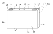
- FIG. 1 is a perspective view showing a non-aqueous electrolyte secondary battery according to the embodiment of the present disclosure.
- FIG. 2 is a cross-sectional view taken along the line II-II in FIG.
- FIG. 3 is a diagram showing a second current collector according to the earlier application.
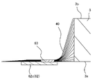
- FIG. 4 is a diagram showing the vicinity of the connection portion between the second current collector and the tab group before bending the tab group.
- FIG. 5 is a diagram showing the vicinity of the connection portion between the second current collector and the tab group after the tab group is bent.
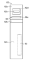
- FIG. 6 is a diagram showing a second current collector according to the present embodiment.
- FIG. 7 is a perspective view showing an electrode body in which the tab group is connected to the second current collector before the tab group is bent.
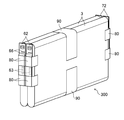
- FIG. 8 is a diagram showing a group of electrode bodies including a plurality of electrode bodies.
- FIG. 9 is a diagram showing a group of electrodes and a sealing plate connected to each other by a first current collector and a second current collector.
- FIG. 10 is a view corresponding to FIG. 6 according to the first modification of the present embodiment.
- FIG. 11 is a diagram corresponding to FIG. 6 according to the second modification of the present embodiment.
- FIG. 12 is a diagram corresponding to FIG. 6 according to the third modification of the present embodiment.
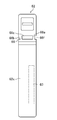
- FIG. 13 is a diagram showing a second current collector according to another embodiment.
- FIG. 14 is a contour diagram showing the distribution of stress applied to the fuse portion.
- the applicant of the present application discloses the structure of the non-aqueous electrolyte secondary battery in the specification of the previous application (Japanese Patent Application No. 2019-174878).
- the non-aqueous electrolyte secondary battery 20 disclosed in the above specification has a tab group 40 of the electrode body 3 housed in the square exterior body 1 and an electrode terminal provided on the sealing plate 2. 8 are electrically connected to each other by the first current collector 61 and the second current collector 62.
- the first current collector 61 is arranged between the electrode body 3 and the sealing plate 2 and is connected to the electrode terminal 8.
- the second current collector 62 is arranged between the electrode body 3 and the side wall 1b of the square exterior body 1, is composed of a flat plate having a surface parallel to the side wall 1b, and is connected to the first current collector 61.
- the tab group 40 extends from the electrode body 3 to the side wall 1b side and is connected to the second current collector 62.
- the second current collector 62 has a fuse portion 66 provided with a fuse hole (slit) 66c along the width direction of the flat plate.
- the fuse portion 66 is a portion of the second current collector 62 having a smaller cross-sectional area than the other portions.
- the tab group 40 is connected to the second current collector 62 toward one side in the width direction of the flat plate. Further, as shown in FIG. 5, the tab group 40 is bent parallel to the side wall 1b (see FIG. 2) on the connection portion 63 side with the second current collector 62.
- the tab group 40 can be bent without bending the second current collector 62. Thereby, a non-aqueous electrolyte secondary battery having a high volumetric energy density can be produced by a simple method.
- FIG. 14 shows the simulation result of the stress distribution applied to the fuse portion 66 by the reaction force applied from the bent tab group 40 to the second current collector 62 when the tab group 40 is bent.
- the inventors of the present application thought that the above problem could be solved by unevenly distributing a portion of the fuse portion 66 having a large cross-sectional area on the other side in the width direction of the flat plate with respect to the slit 66c, and came up with the present invention. ..
- FIGS. 1, 2, 4 and 5 used in the description of the previous application are used as they are.
- FIG. 1 is a perspective view showing a non-aqueous electrolyte secondary battery according to the present disclosure.
- FIG. 2 is a cross-sectional view taken along the line II-II in FIG.
- the non-aqueous electrolyte secondary battery 20 is a battery composed of a bottomed square tubular outer body 1 having an opening and a sealing plate 2 for sealing the opening of the square outer body 1.
- a case 100 is provided.
- the square exterior body 1 has a bottom portion 1a, a pair of first side walls 1b and 1c, and a pair of second side walls 1d and 1e.
- the pair of first side walls 1b and 1c are arranged so as to face each other.
- the pair of second side walls 1d and 1e are arranged so as to face each other.
- the pair of first side walls 1b and 1c are perpendicular to the longitudinal direction of the sealing plate 2, and the area of the pair of first side walls 1b and 1c is smaller than the area of the pair of second side walls 1d and 1e.
- the electrode body 3 including the positive electrode plate 4 and the negative electrode plate 5 is housed together with the electrolyte.
- the electrode body 3 is a flat electrode body in which a positive electrode plate 4 and a negative electrode plate 5 are wound around a separator.
- the winding axis of the electrode body 3 extends perpendicular to the first side walls 1b and 1c and parallel to the second side walls 1d and 1e.
- the electrode body 3 is not limited to the wound electrode body, and may be, for example, a laminated electrode body in which a positive electrode plate 4 and a negative electrode plate 5 are laminated via a separator.
- reference numeral 10 is an external insulating member arranged between the sealing plate 2 and the positive electrode terminal 8.
- Reference numeral 11 is an internal insulating member arranged between the sealing plate 2 and the first positive electrode current collector 61.
- Reference numeral 14 is a box-shaped or bag-shaped insulating sheet arranged inside the square exterior body 1 and accommodating the electrode body 3.
- Reference numeral 15 is an electrolytic solution injection hole provided in the sealing plate 2.
- Reference numeral 16 is a sealing member for sealing the electrolytic solution injection hole 15.
- Reference numeral 17 is a gas discharge valve provided on the sealing plate 2.
- one side is the positive electrode side and the other side is the negative electrode side in the direction in which the winding shaft of the electrode body 3 extends.
- the positive electrode side will be mainly described, and the description of the negative electrode side may be omitted.
- a positive electrode tab group 40 is provided at one end in the direction in which the winding shaft extends. Specifically, the positive electrode tab group 40 extends from one end of the electrode body 3 toward the side wall 1b.
- the positive electrode tab group 40 is formed by laminating a plurality of positive electrode tabs.
- the sealing plate 2 is provided with a positive electrode terminal 8 as an electrode terminal.
- the positive electrode terminal 8 is electrically connected to the positive electrode tab group 40 via the positive electrode current collector 6.
- the positive electrode current collector 6 is composed of a first positive electrode current collector 61 and a second positive electrode current collector 62.
- the first positive electrode current collector 61 has a substantially L-shaped cross section and is arranged between the electrode body 3 and the sealing plate 2. Specifically, the first positive electrode current collector 61 has a first region arranged along the sealing plate 2 and a second region bent from an end portion of the first region. The second region extends toward the bottom 1a along the first side wall 1b. The first positive electrode current collector 61 is connected to the positive electrode terminal 8.
- the second positive electrode current collector 62 is arranged between the electrode body 3 and the first side wall 1b of the square exterior body 1. Specifically, the second positive electrode current collector 62 is composed of a flat plate having a surface parallel to the first side wall 1b, and extends along the first side wall 1b toward the bottom portion 1a. The second positive electrode current collector 62 is connected to the first positive electrode current collector 61.
- FIG. 6 shows the second positive electrode current collector 62.
- the second positive electrode current collector 62 has a current collector connecting portion 62a, an inclined portion 62b, and a tab connecting portion 62c.
- the current collector connecting portion 62a is connected to the first positive electrode current collector 61.
- the positive electrode tab group 40 is connected to the tab connection portion 62c.
- the inclined portion 62b connects the current collector connecting portion 62a and the tab connecting portion 62c, and is inclined with respect to both.
- the current collector connecting portion 62a is provided with a recess 62d.
- the recess 62d is provided with a through hole 62e. In the recess 62d, the current collector connecting portion 62a is joined to the first positive electrode current collector 61.
- the second positive electrode current collector 62 is provided with a fuse portion 66.
- the details of the fuse unit 66 will be described later.
- FIG. 4 shows the vicinity of the connection portion between the second positive electrode current collector 62 and the positive electrode tab group 40 before bending the positive electrode tab group 40.
- FIG. 7 shows an electrode body 3 in which the positive electrode tab group 40 is connected to the second positive electrode current collector 62 before the positive electrode tab group 40 is bent.
- the positive electrode tab group 40 is connected to the tab connection portion 62c of the second positive electrode current collector 62. Specifically, as shown in FIG. 4, before the positive electrode tab group 40 is bent, the positive electrode tab group 40 is arranged on the tab connection portion 62c of the second positive electrode current collector 62, and the tab connection portion 62c and the positive electrode tab group 40 are arranged.
- the connecting portion 63 is formed by joining (welding) the positive electrode tab group 40.
- the positive electrode tab group 40 is connected to the tab connection portion 62c of the second positive electrode current collector 62 toward one side in the width direction (right side in FIG. 4) of the flat plate. That is, the connecting portion 63 between the positive electrode tab group 40 and the tab connecting portion 62c is closer to the root side (one side in the width direction, right side in FIG. 4) of the positive electrode tab group 40 in the width direction of the flat plate. As a result, when the positive electrode tab group 40 is bent, a curved shape can be more reliably formed in the vicinity of the root of the positive electrode tab group 40.
- FIG. 5 shows the vicinity of the connection portion between the second positive electrode current collector 62 and the positive electrode tab group 40 after the positive electrode tab group 40 is bent.
- the tab connection portion 62c in the second positive electrode current collector 62 which is arranged substantially parallel to the first main surface 3a and the second main surface 3b of the electrode body 3 (see FIGS. 4 and 7), is connected to the positive electrode tab group 40. Is bent so that the direction is substantially perpendicular to the winding axis of the electrode body 3. That is, the positive electrode tab group 40 is bent parallel to the first side wall 1b on the connection portion 63 side with the second positive electrode current collector 62.
- the bent positive electrode tab group 40 is fixed to the electrode body 3 by the tape 80.
- the current collector connecting portion 62a of the second positive electrode current collector 62 is provided with a fuse portion 66.
- the fuse portion 66 is provided with a slit 66c along the width direction of the flat plate.
- the fuse portion 66 is composed of a portion 66a located on one side of the flat plate in the width direction (right side in FIG. 6) and a portion 66b located on the other side in the width direction of the flat plate (left side in FIG. 6) with respect to the slit 66c. There is. Since the portions 66a and 66b have a smaller cross-sectional area than the other portions of the flat plate, the portions 66a and / or the portions 66b are melted when an overcurrent flows through the second positive electrode current collector 62.
- the cross-sectional area refers to the area in the cross section parallel to the width direction of the flat plate.
- the slit 66c is eccentric to one side in the width direction of the flat plate.
- the portion 66b becomes wider than the portion 66a. That is, in the fuse portion 66, the wide portion 66b is unevenly distributed on the other side in the width direction of the flat plate with respect to the slit 66c.
- connection portion 63 of the second positive electrode current collector 62 with the positive electrode tab group 40 is closer to one side in the width direction of the flat plate. Therefore, strong stress is unevenly distributed on the other side of the flat plate in the width direction with respect to the slit 66c in the fuse portion 66 (see FIG. 14). As shown in FIG. 3, when the slit 66c is provided in the center of the flat plate in the width direction, the fuse portion 66 may be deformed due to the uneven distribution of the stress.
- the strength of the portion 66b where the strong stress is unevenly distributed is increased by unevenly distributing the portion 66b having a large cross-sectional area on the other side in the width direction of the flat plate with respect to the slit 66c. There is.
- the cross-sectional area of the portion 66a on the one side in the width direction is reduced by the amount that the cross-sectional area of the portion 66b on the other side in the width direction of the flat plate is increased with respect to the slit 66c in the fuse portion 66. That is, by reducing the cross-sectional area of the portion 66a on one side in the width direction in which the stress is relatively weak, the cross-sectional area of the fuse portion 66 as a whole is prevented from becoming as large as possible. As a result, the function as the fuse unit 66 can be guaranteed.
- the fuse portion 66 by widening the portion 66b on the other side in the width direction of the flat plate with respect to the slit 66c, the portion having a large cross-sectional area is unevenly distributed on the other side in the width direction of the flat plate, so that the structure is simple. is there.
- the wide portion 66b is easily unevenly distributed on the other side in the width direction of the flat plate, and the narrow portion 66a is unevenly distributed on one side in the width direction of the flat plate. It can be unevenly distributed on the side.
- the fuse portion 66 is formed in the second positive electrode current collector 62 with the wide portion 66b unevenly distributed on the other side in the width direction of the flat plate with respect to the slit 66c.
- the specific configuration is not particularly limited, and is appropriately determined according to the processing of the slit 66c, the assembly of the second positive electrode current collector 62, and the like.
- FIG. 10 shows the second positive electrode current collector 62 according to the first modification of the present embodiment.
- the fuse portion 66 is provided with a notch 66f on one side (portion 66a) of the flat plate in the width direction with respect to the slit 66c.
- the portions 66a and 66b on both sides of the slit 66c need to have a certain width dimension, and the width dimension of the portion 66a may not be made as narrow as desired. According to such a configuration, the cross-sectional area of the portion 66a can be reduced by forming the notch 66f with respect to the portion 66a by cutting after pressing.
- FIG. 11 shows the second positive electrode current collector 62 according to the second modification of the present embodiment.
- the fuse portion 66 is provided with an extending portion 66g extending in the width direction on the other side (part 66b) of the flat plate in the width direction with respect to the slit 66c.
- the width dimension of the portion 66a cannot be made as narrow as desired as in the first modification, it is conceivable to reduce the cross-sectional area of the portion 66a by reducing the plate thickness of the flat plate. According to such a configuration, the reduction in the cross-sectional area of the portion 66b due to the reduction in the plate thickness of the flat plate can be increased by providing the extending portion 66g.
- FIG. 12 shows the second positive electrode current collector 62 according to the third modification of the present embodiment.
- the fuse portion 66 is provided with a protruding portion 66h protruding in the thickness direction on the other side (portion 66b) in the width direction of the flat plate with respect to the slit 66c.
- the plate thickness portion may be unevenly distributed on the other side (part 66b) in the width direction of the flat plate with respect to the slit 66c.
- the negative electrode side has the same configuration as the positive electrode side.
- reference numeral 9 is a negative electrode terminal
- reference numeral 50 is a negative electrode tab group
- reference numeral 7 is a negative electrode current collector
- reference numeral 71 is a first negative electrode current collector
- reference numeral 72. 2 indicates a second negative electrode current collector
- reference numeral 12 indicates an external insulating member
- reference numeral 13 indicates an internal insulating member.
- reference numeral 72a is a current collector connection portion
- reference numeral 72b is an inclined portion
- reference numeral 72c is a tab connection portion.
- the portion 66a on one side of the flat plate in the width direction with respect to the slit 66c in the fuse portion 66 may be omitted. That is, the slit 66c may be a notch extending from one side end portion in the width direction of the flat plate in the fuse portion 66 to the vicinity of the other side end portion in the width direction.
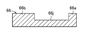
- the fuse portion 66 may be provided with a thin portion 66j that is thinner than other portions of the flat plate along the width direction of the flat plate, instead of the slit 66c.
- the non-aqueous electrolyte secondary battery 20 may include a plurality of electrode bodies 3.
- FIG. 8 shows an electrode body group 300 including a plurality of electrode bodies 3.
- the non-aqueous electrolyte secondary battery 20 includes a plurality (two) of electrode bodies 3.
- a second current collector 62 is connected to the positive electrode tab group 40 of each electrode body 3.
- the electrode body group 300 is formed by arranging the plurality of electrode bodies 3 and 3 and fixing them together with the tape 90.
- FIG. 9 shows an electrode body group 300 and a sealing plate 2 connected to each other by a first positive electrode current collector 61 and a second positive electrode current collector 62. As shown in FIG. 9, the second positive electrode current collector 62 provided in each electrode body 3 is connected to the first positive electrode current collector 61 provided in the sealing plate 2.
Landscapes
- Chemical & Material Sciences (AREA)
- Chemical Kinetics & Catalysis (AREA)
- Electrochemistry (AREA)
- General Chemical & Material Sciences (AREA)
- Engineering & Computer Science (AREA)
- Manufacturing & Machinery (AREA)
- Connection Of Batteries Or Terminals (AREA)
Abstract
Description
1b 第1側壁(側壁)
2 封口板
3 電極体
4 正極板
5 負極板
8 正極端子(電極端子)
20 非水電解質二次電池
40 正極タブ群(タブ群)
61 第1正極集電体(第1集電体)
62 第2正極集電体(第2集電体)
63 接続部
66 ヒューズ部
66a 部位
66b 部位
66c スリット
66f 切り欠き
66g 延出部
66h 突出部
66j 薄肉部
Claims (9)
- 正極板と負極板とを含む電極体と、
開口を有し、前記電極体を収容した角形外装体と、
前記開口を封口した封口板と、
前記封口板に設けられた電極端子と、
前記電極体と前記封口板との間に配置され、前記電極端子に接続された第1集電体と、
前記電極体と、前記角形外装体における側壁との間に配置され、前記第1集電体に接続された第2集電体と、
前記電極体から前記側壁側に延出し、前記第2集電体に接続されたタブ群と
を備え、
前記第2集電体は、前記側壁に平行な面を有する平板からなるとともに、該平板の幅方向に沿ってスリットが設けられたヒューズ部を有し、
前記タブ群は、前記平板の幅方向一方側に寄って、前記第2集電体に接続され、且つ、該第2集電体との接続部側において、前記側壁に平行に折り曲げられており、
前記ヒューズ部は、前記スリットに対し、断面積の大きい部位が、前記平板の幅方向他方側に偏在している、非水電解質二次電池。 - 前記ヒューズ部は、前記スリットに対し、幅広の部位が、前記平板の幅方向他方側に偏在している、請求項1に記載の非水電解質二次電池。
- 前記スリットは、前記平板の幅方向一方側に偏心している、請求項2に記載の非水電解質二次電池。
- 前記ヒューズ部は、前記スリットに対し、前記平板の幅方向一方側に切り欠きが設けられている、請求項2に記載の非水電解質二次電池。
- 前記ヒューズ部は、前記スリットに対し、前記平板の幅方向他方側に、幅方向に延出する延出部が設けられている、請求項2に記載の非水電解質二次電池。
- 前記ヒューズ部は、前記スリットに対し、前記平板の幅方向他方側に、厚み方向に突出する突出部が設けられている、請求項1に記載の非水電解質二次電池。
- 前記ヒューズ部は、前記スリットに対し、板厚の部位が、前記平板の幅方向他方側に偏在している、請求項1に記載の非水電解質二次電池。
- 前記ヒューズ部には、前記スリットに代えて、前記平板の幅方向に沿って、該平板の他の部位よりも厚みの薄い薄肉部が設けられている、請求項1に記載の非水電解質二次電池。
- 前記電極体を複数備え、
前記各電極体の前記タブ群に、それぞれ前記第2集電体が接続されており、
前記各第2集電体は、前記第1集電体に接続されている、請求項1に記載の非水電解質二次電池。
Priority Applications (4)
| Application Number | Priority Date | Filing Date | Title |
|---|---|---|---|
| CN202080088439.8A CN114830432B (zh) | 2019-12-19 | 2020-11-20 | 非水电解质二次电池 |
| US17/787,126 US20230033391A1 (en) | 2019-12-19 | 2020-11-20 | Non-aqueous electrolyte secondary battery |
| JP2021565396A JP7606470B2 (ja) | 2019-12-19 | 2020-11-20 | 非水電解質二次電池 |
| EP20903787.8A EP4080640A4 (en) | 2019-12-19 | 2020-11-20 | NON-AQUEOUS ELECTROLYTE SECONDARY BATTERY |
Applications Claiming Priority (2)
| Application Number | Priority Date | Filing Date | Title |
|---|---|---|---|
| JP2019229170 | 2019-12-19 | ||
| JP2019-229170 | 2019-12-19 |
Publications (1)
| Publication Number | Publication Date |
|---|---|
| WO2021124797A1 true WO2021124797A1 (ja) | 2021-06-24 |
Family
ID=76477252
Family Applications (1)
| Application Number | Title | Priority Date | Filing Date |
|---|---|---|---|
| PCT/JP2020/043375 Ceased WO2021124797A1 (ja) | 2019-12-19 | 2020-11-20 | 非水電解質二次電池 |
Country Status (5)
| Country | Link |
|---|---|
| US (1) | US20230033391A1 (ja) |
| EP (1) | EP4080640A4 (ja) |
| JP (1) | JP7606470B2 (ja) |
| CN (1) | CN114830432B (ja) |
| WO (1) | WO2021124797A1 (ja) |
Cited By (2)
| Publication number | Priority date | Publication date | Assignee | Title |
|---|---|---|---|---|
| CN115995659A (zh) * | 2021-10-19 | 2023-04-21 | 泰星能源解决方案有限公司 | 二次电池 |
| EP4254642A1 (en) * | 2022-03-29 | 2023-10-04 | Prime Planet Energy & Solutions, Inc. | Power storage device |
Families Citing this family (2)
| Publication number | Priority date | Publication date | Assignee | Title |
|---|---|---|---|---|
| JP7812358B2 (ja) * | 2023-08-10 | 2026-02-09 | プライムプラネットエナジー&ソリューションズ株式会社 | 二次電池 |
| WO2025178948A1 (en) * | 2024-02-20 | 2025-08-28 | Enovix Corporation | Increasing safety of energy manipulation devices |
Citations (6)
| Publication number | Priority date | Publication date | Assignee | Title |
|---|---|---|---|---|
| JP2011258550A (ja) | 2010-06-11 | 2011-12-22 | Sb Limotive Co Ltd | 二次電池 |
| JP2012015102A (ja) * | 2010-06-30 | 2012-01-19 | Sb Limotive Co Ltd | 二次電池 |
| JP2013115042A (ja) * | 2011-11-25 | 2013-06-10 | Samsung Sdi Co Ltd | 2次電池 |
| US20190067664A1 (en) * | 2017-08-31 | 2019-02-28 | Samsung Sdi Co., Ltd. | Secondary battery |
| JP2019087341A (ja) * | 2017-11-02 | 2019-06-06 | 株式会社Gsユアサ | 蓄電素子 |
| JP2019174878A (ja) | 2018-03-27 | 2019-10-10 | 日本電気株式会社 | 情報処理装置、情報処理方法および情報処理プログラム |
Family Cites Families (10)
| Publication number | Priority date | Publication date | Assignee | Title |
|---|---|---|---|---|
| JP2002222626A (ja) * | 2001-01-25 | 2002-08-09 | Alps Electric Co Ltd | 電流ヒューズ、及びこの電流ヒューズを用いた電池 |
| KR101683209B1 (ko) * | 2011-12-06 | 2016-12-07 | 삼성에스디아이 주식회사 | 이차 전지 |
| JP6293501B2 (ja) * | 2014-01-29 | 2018-03-14 | 株式会社東芝 | 二次電池、及び二次電池の製造方法 |
| KR102306440B1 (ko) * | 2014-08-14 | 2021-09-29 | 삼성에스디아이 주식회사 | 이차 전지 |
| JP6476746B2 (ja) * | 2014-10-27 | 2019-03-06 | 株式会社Gsユアサ | 蓄電素子、電源モジュール及び蓄電素子の製造方法 |
| JP6891930B2 (ja) * | 2015-03-30 | 2021-06-18 | 三洋電機株式会社 | 角形二次電池及びそれを用いた組電池 |
| JP7035348B6 (ja) * | 2017-06-29 | 2022-04-01 | 三洋電機株式会社 | 角形二次電池及びその製造方法 |
| EP3451415B1 (en) * | 2017-08-31 | 2020-03-25 | Samsung SDI Co., Ltd. | Secondary battery |
| US12176580B2 (en) * | 2019-09-26 | 2024-12-24 | Sanyo Electric Co., Ltd. | Secondary battery and method for manufacturing same |
| WO2021124796A1 (ja) * | 2019-12-19 | 2021-06-24 | パナソニック株式会社 | 非水電解質二次電池 |
-
2020
- 2020-11-20 US US17/787,126 patent/US20230033391A1/en active Pending
- 2020-11-20 CN CN202080088439.8A patent/CN114830432B/zh active Active
- 2020-11-20 EP EP20903787.8A patent/EP4080640A4/en active Pending
- 2020-11-20 WO PCT/JP2020/043375 patent/WO2021124797A1/ja not_active Ceased
- 2020-11-20 JP JP2021565396A patent/JP7606470B2/ja active Active
Patent Citations (6)
| Publication number | Priority date | Publication date | Assignee | Title |
|---|---|---|---|---|
| JP2011258550A (ja) | 2010-06-11 | 2011-12-22 | Sb Limotive Co Ltd | 二次電池 |
| JP2012015102A (ja) * | 2010-06-30 | 2012-01-19 | Sb Limotive Co Ltd | 二次電池 |
| JP2013115042A (ja) * | 2011-11-25 | 2013-06-10 | Samsung Sdi Co Ltd | 2次電池 |
| US20190067664A1 (en) * | 2017-08-31 | 2019-02-28 | Samsung Sdi Co., Ltd. | Secondary battery |
| JP2019087341A (ja) * | 2017-11-02 | 2019-06-06 | 株式会社Gsユアサ | 蓄電素子 |
| JP2019174878A (ja) | 2018-03-27 | 2019-10-10 | 日本電気株式会社 | 情報処理装置、情報処理方法および情報処理プログラム |
Non-Patent Citations (1)
| Title |
|---|
| See also references of EP4080640A4 |
Cited By (7)
| Publication number | Priority date | Publication date | Assignee | Title |
|---|---|---|---|---|
| CN115995659A (zh) * | 2021-10-19 | 2023-04-21 | 泰星能源解决方案有限公司 | 二次电池 |
| EP4170814A1 (en) * | 2021-10-19 | 2023-04-26 | Prime Planet Energy & Solutions, Inc. | Secondary battery |
| JP2023061187A (ja) * | 2021-10-19 | 2023-05-01 | プライムプラネットエナジー&ソリューションズ株式会社 | 二次電池 |
| JP7463327B2 (ja) | 2021-10-19 | 2024-04-08 | プライムプラネットエナジー&ソリューションズ株式会社 | 二次電池 |
| KR102930794B1 (ko) | 2021-10-19 | 2026-02-26 | 프라임 플래닛 에너지 앤드 솔루션즈 가부시키가이샤 | 이차 전지 |
| EP4254642A1 (en) * | 2022-03-29 | 2023-10-04 | Prime Planet Energy & Solutions, Inc. | Power storage device |
| US12562438B2 (en) | 2022-03-29 | 2026-02-24 | Prime Planet Energy & Solutions, Inc. | Power storage device |
Also Published As
| Publication number | Publication date |
|---|---|
| US20230033391A1 (en) | 2023-02-02 |
| CN114830432B (zh) | 2024-01-09 |
| JP7606470B2 (ja) | 2024-12-25 |
| EP4080640A4 (en) | 2024-03-20 |
| JPWO2021124797A1 (ja) | 2021-06-24 |
| CN114830432A (zh) | 2022-07-29 |
| EP4080640A1 (en) | 2022-10-26 |
Similar Documents
| Publication | Publication Date | Title |
|---|---|---|
| WO2021124797A1 (ja) | 非水電解質二次電池 | |
| US20250192345A1 (en) | Secondary battery | |
| EP2299523B1 (en) | Battery and method of manufacturing same | |
| CN109891635B (zh) | 方形二次电池 | |
| EP2827399B1 (en) | Rechargeable battery | |
| JP6599129B2 (ja) | 角形二次電池及びそれを用いた組電池、並びにその製造方法 | |
| EP2388844B1 (en) | Rechargeable battery | |
| JP6550848B2 (ja) | 角形二次電池 | |
| CN110326133A (zh) | 方形二次电池以及其制造方法 | |
| CN112993471A (zh) | 方形二次电池以及组电池 | |
| KR20100108854A (ko) | 이차전지 | |
| CN107665968B (zh) | 二次电池及其制造方法、以及使用该二次电池的组电池 | |
| JP2016219124A (ja) | 角形二次電池及びそれを用いた組電池、並びにその製造方法 | |
| EP4131529A1 (en) | Secondary battery | |
| JP7558199B2 (ja) | 非水電解質二次電池 | |
| CN106558656B (zh) | 方形二次电池 | |
| CN106558673B (zh) | 方形二次电池 | |
| CN108232280B (zh) | 方形二次电池及其制造方法 | |
| US10256441B2 (en) | Rechargeable battery | |
| JP2018006138A (ja) | 蓄電装置用電極およびそれを用いた蓄電装置 | |
| CN108232310B (zh) | 方形二次电池及其制造方法 | |
| CN109792030B (zh) | 二次电池、二次电池的制造方法及二次电池用导电构件的制造方法 | |
| JP2016115437A (ja) | 蓄電装置 | |
| WO2021060006A1 (ja) | 二次電池 | |
| US12597681B2 (en) | Secondary battery comprising insulated tab group |
Legal Events
| Date | Code | Title | Description |
|---|---|---|---|
| 121 | Ep: the epo has been informed by wipo that ep was designated in this application |
Ref document number: 20903787 Country of ref document: EP Kind code of ref document: A1 |
|
| ENP | Entry into the national phase |
Ref document number: 2021565396 Country of ref document: JP Kind code of ref document: A |
|
| NENP | Non-entry into the national phase |
Ref country code: DE |
|
| ENP | Entry into the national phase |
Ref document number: 2020903787 Country of ref document: EP Effective date: 20220719 |
|
| WWG | Wipo information: grant in national office |
Ref document number: 202247039912 Country of ref document: IN |