WO2021124828A1 - 二次電池、二次電池の製造方法、電子機器、電動工具 - Google Patents
二次電池、二次電池の製造方法、電子機器、電動工具 Download PDFInfo
- Publication number
- WO2021124828A1 WO2021124828A1 PCT/JP2020/044024 JP2020044024W WO2021124828A1 WO 2021124828 A1 WO2021124828 A1 WO 2021124828A1 JP 2020044024 W JP2020044024 W JP 2020044024W WO 2021124828 A1 WO2021124828 A1 WO 2021124828A1
- Authority
- WO
- WIPO (PCT)
- Prior art keywords
- battery
- joined
- welding
- outer peripheral
- peripheral portion
- Prior art date
- Legal status (The legal status is an assumption and is not a legal conclusion. Google has not performed a legal analysis and makes no representation as to the accuracy of the status listed.)
- Ceased
Links
Images


Classifications
-
- H—ELECTRICITY
- H01—ELECTRIC ELEMENTS
- H01M—PROCESSES OR MEANS, e.g. BATTERIES, FOR THE DIRECT CONVERSION OF CHEMICAL ENERGY INTO ELECTRICAL ENERGY
- H01M50/00—Constructional details or processes of manufacture of the non-active parts of electrochemical cells other than fuel cells, e.g. hybrid cells
- H01M50/30—Arrangements for facilitating escape of gases
- H01M50/342—Non-re-sealable arrangements
- H01M50/3425—Non-re-sealable arrangements in the form of rupturable membranes or weakened parts, e.g. pierced with the aid of a sharp member
-
- H—ELECTRICITY
- H01—ELECTRIC ELEMENTS
- H01M—PROCESSES OR MEANS, e.g. BATTERIES, FOR THE DIRECT CONVERSION OF CHEMICAL ENERGY INTO ELECTRICAL ENERGY
- H01M10/00—Secondary cells; Manufacture thereof
- H01M10/04—Construction or manufacture in general
- H01M10/0431—Cells with wound or folded electrodes
-
- H—ELECTRICITY
- H01—ELECTRIC ELEMENTS
- H01M—PROCESSES OR MEANS, e.g. BATTERIES, FOR THE DIRECT CONVERSION OF CHEMICAL ENERGY INTO ELECTRICAL ENERGY
- H01M10/00—Secondary cells; Manufacture thereof
- H01M10/05—Accumulators with non-aqueous electrolyte
- H01M10/058—Construction or manufacture
- H01M10/0587—Construction or manufacture of accumulators having only wound construction elements, i.e. wound positive electrodes, wound negative electrodes and wound separators
-
- H—ELECTRICITY
- H01—ELECTRIC ELEMENTS
- H01M—PROCESSES OR MEANS, e.g. BATTERIES, FOR THE DIRECT CONVERSION OF CHEMICAL ENERGY INTO ELECTRICAL ENERGY
- H01M50/00—Constructional details or processes of manufacture of the non-active parts of electrochemical cells other than fuel cells, e.g. hybrid cells
- H01M50/10—Primary casings; Jackets or wrappings
- H01M50/102—Primary casings; Jackets or wrappings characterised by their shape or physical structure
- H01M50/107—Primary casings; Jackets or wrappings characterised by their shape or physical structure having curved cross-section, e.g. round or elliptic
-
- H—ELECTRICITY
- H01—ELECTRIC ELEMENTS
- H01M—PROCESSES OR MEANS, e.g. BATTERIES, FOR THE DIRECT CONVERSION OF CHEMICAL ENERGY INTO ELECTRICAL ENERGY
- H01M50/00—Constructional details or processes of manufacture of the non-active parts of electrochemical cells other than fuel cells, e.g. hybrid cells
- H01M50/10—Primary casings; Jackets or wrappings
- H01M50/147—Lids or covers
-
- H—ELECTRICITY
- H01—ELECTRIC ELEMENTS
- H01M—PROCESSES OR MEANS, e.g. BATTERIES, FOR THE DIRECT CONVERSION OF CHEMICAL ENERGY INTO ELECTRICAL ENERGY
- H01M50/00—Constructional details or processes of manufacture of the non-active parts of electrochemical cells other than fuel cells, e.g. hybrid cells
- H01M50/10—Primary casings; Jackets or wrappings
- H01M50/147—Lids or covers
- H01M50/166—Lids or covers characterised by the methods of assembling casings with lids
- H01M50/169—Lids or covers characterised by the methods of assembling casings with lids by welding, brazing or soldering
-
- H—ELECTRICITY
- H01—ELECTRIC ELEMENTS
- H01M—PROCESSES OR MEANS, e.g. BATTERIES, FOR THE DIRECT CONVERSION OF CHEMICAL ENERGY INTO ELECTRICAL ENERGY
- H01M50/00—Constructional details or processes of manufacture of the non-active parts of electrochemical cells other than fuel cells, e.g. hybrid cells
- H01M50/30—Arrangements for facilitating escape of gases
- H01M50/342—Non-re-sealable arrangements
-
- H—ELECTRICITY
- H01—ELECTRIC ELEMENTS
- H01M—PROCESSES OR MEANS, e.g. BATTERIES, FOR THE DIRECT CONVERSION OF CHEMICAL ENERGY INTO ELECTRICAL ENERGY
- H01M50/00—Constructional details or processes of manufacture of the non-active parts of electrochemical cells other than fuel cells, e.g. hybrid cells
- H01M50/50—Current conducting connections for cells or batteries
- H01M50/572—Means for preventing undesired use or discharge
-
- H—ELECTRICITY
- H01—ELECTRIC ELEMENTS
- H01M—PROCESSES OR MEANS, e.g. BATTERIES, FOR THE DIRECT CONVERSION OF CHEMICAL ENERGY INTO ELECTRICAL ENERGY
- H01M2220/00—Batteries for particular applications
- H01M2220/30—Batteries in portable systems, e.g. mobile phone, laptop
-
- Y—GENERAL TAGGING OF NEW TECHNOLOGICAL DEVELOPMENTS; GENERAL TAGGING OF CROSS-SECTIONAL TECHNOLOGIES SPANNING OVER SEVERAL SECTIONS OF THE IPC; TECHNICAL SUBJECTS COVERED BY FORMER USPC CROSS-REFERENCE ART COLLECTIONS [XRACs] AND DIGESTS
- Y02—TECHNOLOGIES OR APPLICATIONS FOR MITIGATION OR ADAPTATION AGAINST CLIMATE CHANGE
- Y02E—REDUCTION OF GREENHOUSE GAS [GHG] EMISSIONS, RELATED TO ENERGY GENERATION, TRANSMISSION OR DISTRIBUTION
- Y02E60/00—Enabling technologies; Technologies with a potential or indirect contribution to GHG emissions mitigation
- Y02E60/10—Energy storage using batteries
-
- Y—GENERAL TAGGING OF NEW TECHNOLOGICAL DEVELOPMENTS; GENERAL TAGGING OF CROSS-SECTIONAL TECHNOLOGIES SPANNING OVER SEVERAL SECTIONS OF THE IPC; TECHNICAL SUBJECTS COVERED BY FORMER USPC CROSS-REFERENCE ART COLLECTIONS [XRACs] AND DIGESTS
- Y02—TECHNOLOGIES OR APPLICATIONS FOR MITIGATION OR ADAPTATION AGAINST CLIMATE CHANGE
- Y02P—CLIMATE CHANGE MITIGATION TECHNOLOGIES IN THE PRODUCTION OR PROCESSING OF GOODS
- Y02P70/00—Climate change mitigation technologies in the production process for final industrial or consumer products
- Y02P70/50—Manufacturing or production processes characterised by the final manufactured product
Definitions
- the present invention relates to a secondary battery, a method for manufacturing a secondary battery, an electronic device, and a power tool.
- Lithium-ion batteries are being used for electric tools, electric vehicles, etc. Since the batteries of electronic devices including these large devices may be damaged by external impact, the impact resistance of the batteries is one of the important factors, and various development studies have been conducted. There is.
- Patent Document 1 discloses that the resistance value of the battery is lowered by laser welding the battery lid and the safety cover of the safety valve mechanism.
- Patent Document 1 uses a laser welding method for welding the battery lid and the safety cover of the safety valve mechanism, there is a problem that it is vulnerable to repeated impacts and has low impact resistance.
- one of the objects of the present invention is to provide a battery having high vibration resistance.
- a band-shaped positive electrode and a band-shaped negative electrode are laminated via a separator, and an electrode winding body having a wound structure and an electrolytic solution are housed in a battery can.
- It has a battery lid that closes the open end of the battery can, and a safety valve mechanism provided between the battery lid and the electrode winding body.
- the safety valve mechanism has at least a safety cover The outer circumference of the battery lid and the outer circumference of the safety cover are joined, The area of the region where the outer peripheral portion of the battery lid and the outer peripheral portion of the safety cover are joined is a secondary battery having an area of 18.1% or more and 25.0% or less of the radial cross-sectional area of the battery.
- a band-shaped positive electrode and a band-shaped negative electrode are laminated via a separator, and an electrode winding body having a wound structure and an electrolytic solution are housed in a battery can. It has a battery lid that closes the open end of the battery can, and a safety valve mechanism provided between the battery lid and the electrode winding body. It is a method of manufacturing secondary batteries.
- the safety valve mechanism has at least a safety cover The outer peripheral part of the battery lid and the outer peripheral part of the safety cover are joined by a welding method.
- a method for manufacturing a secondary battery wherein the area of the region where the outer peripheral portion of the battery lid and the outer peripheral portion of the safety cover are joined is 18.1% or more and 25.0% or less of the cross-sectional area in the radial direction of the battery.
- the present invention it is possible to realize a battery in which the portion where the battery lid and the safety cover are joined is resistant to repeated vibrations. It should be noted that the contents of the present invention are not limitedly interpreted by the effects exemplified in the present specification.
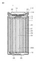
- FIG. 1 is a schematic view of a battery of one embodiment.
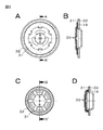
- FIG. 2A is a view of a relatively large battery safety cover and a battery cover integrated from the safety cover side
- FIG. 2B is a cross-sectional view taken along the line AA'of FIG. 2A
- 2C is a view of a relatively small battery safety cover and a battery cover integrated from the safety cover side
- FIG. 2D is a cross-sectional view taken along the line BB'of FIG. 2C.
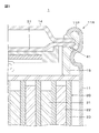
- FIG. 3 is a diagram showing a part of a battery in which a safety cover having a convex portion is arranged.
- FIG. 4 is a connection diagram used for explaining a battery pack as an application example of the present invention.
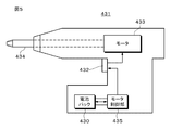
- FIG. 5 is a connection diagram used for explaining a power tool as an application example of the present invention.
- FIG. 6 is a connection diagram used for explaining an electric vehicle as an application example of the present invention.
- a cylindrical lithium ion battery will be described as an example of the secondary battery.
- FIG. 1 is a schematic cross-sectional view of the lithium ion battery 1.
- the lithium ion battery 1 is a cylindrical lithium ion battery 1 in which the electrode winding body 20 is housed inside the battery can 11.
- the lithium ion battery 1 includes a pair of insulators 12 and 13 and an electrode winding body 20 inside a cylindrical battery can 11.
- the lithium ion battery 1 may further include any one or more of a heat-sensitive resistance (PTC) element, a reinforcing member, and the like inside the battery can 11.
- PTC heat-sensitive resistance
- the battery can 11 is mainly a member for accommodating the electrode winding body 20.
- the battery can 11 is a cylindrical container in which one end is open and the other end is closed. That is, the battery can 11 has an open end portion (open end portion).
- the battery can 11 contains any one or more of metal materials such as iron, aluminum and alloys thereof. However, on the surface of the battery can 11, any one or more of the metal materials such as nickel may be plated.
- the insulators 12 and 13 are sheet-like members having a surface substantially perpendicular to the winding axis direction (vertical direction in FIG. 1) of the electrode winding body 20.
- the insulators 12 and 13 are arranged so as to sandwich the electrode winding body 20 with each other.
- Bakelite includes paper bakelite and cloth bakelite, which are produced by applying a phenol resin to paper or cloth and then heating it.
- a battery lid 14 and a safety valve mechanism 30 are crimped to the open end of the battery can 11 via a gasket 15, and a crimping structure 11R (crimp structure) is formed.
- a crimping structure 11R crimp structure
- the battery lid 14 is a member that closes the open end of the battery can 11 in a state where the electrode winding body 20 and the like are housed inside the battery can 11, and is made of iron plated with nickel. ing.
- the battery lid 14 contains the same material as the material for forming the battery can 11.
- the central region of the battery lid 14 projects in the vertical direction of FIG.
- the gasket 15 is mainly interposed between the bent portion 11P (also referred to as a crimp portion) of the battery can 11 and the battery lid 14, thereby forming a gap between the bent portion 11P and the battery lid 14. It is a member to be sealed.
- asphalt may be coated on the surface of the gasket 15.
- Gasket 15 contains an insulating material.
- the type of insulating material is not particularly limited, but is a polymer material such as polybutylene terephthalate (PBT) and polypropylene (PP). This is because the gap between the bent portion 11P and the battery lid 14 is sufficiently sealed while the battery can 11 and the battery lid 14 are electrically separated from each other.
- PBT polybutylene terephthalate
- PP polypropylene
- the safety valve mechanism 30 mainly releases the internal pressure of the battery can 11 by releasing the sealed state of the battery can 11 as necessary when the internal pressure (internal pressure) of the battery can 11 rises.
- the cause of the increase in the internal pressure of the battery can 11 is gas generated due to the decomposition reaction of the electrolytic solution during charging and discharging.
- the safety cover 31 is a substantially circular plate-shaped member and is also called a valve body.
- the safety cover 31 is made of, for example, aluminum.
- the central portion of the safety cover 31 may have a protrusion protruding in the direction of the electrode winding body 20.
- the outer peripheral portion of the safety cover 31 is joined to the outer peripheral portion of the battery lid 14 by welding.
- the welding method is, for example, an ultrasonic welding method.
- a part of the joined region 32 between the safety cover 31 and the battery lid 14 is covered with the gasket 15 (FIG. 1) and fixed by the battery can 11.
- the safety cover 31 and the battery lid 14 have a structure as shown in FIGS.
- FIGS. 2C and 2D when the outer diameter of the battery is relatively large (for example, when the outer diameter is about 18 mm or about 20 mm).
- the structure is as shown in FIGS. 2C and 2D.
- the welded region 32 is the region where the hatches of FIGS. 2A and 2C are attached.
- the area of the region 32 where the outer peripheral portion of the battery lid 14 and the outer peripheral portion of the safety cover 31 are joined by welding is preferably at least a threshold value in order to be strong against an impact from the outside of the battery 1, and inside the battery 1. In order for the internal gas to easily escape when the pressure rises due to the generation of gas, a value of a certain value or less is preferable.
- the area of the region 32 in which the outer peripheral portion of the battery lid 14 and the outer peripheral portion of the safety cover 31 are joined by welding is, for example, 18.5% or more of the radial cross-sectional area of the battery. It is preferably 25.0% or less.
- a band-shaped positive electrode 21 and a band-shaped negative electrode 22 are spirally wound with a separator 23 sandwiched between them, and are housed in a battery can 11 in a state of being impregnated with an electrolytic solution.
- the positive electrode 21 and the negative electrode 22 have a positive electrode active material layer and a negative electrode active material layer formed on one or both sides of the positive electrode current collector and the negative electrode current collector, respectively.
- the material of the positive electrode current collector is a metal foil containing aluminum or an aluminum alloy.
- the material of the negative electrode current collector is a metal foil containing nickel, nickel alloy, copper or copper alloy.
- the separator 23 is a porous and insulating film that electrically insulates the positive electrode 21 and the negative electrode 22 while allowing the movement of lithium ions.
- a space (central space 20C) created when the positive electrode 21, the negative electrode 22 and the separator 23 are wound is provided at the center of the electrode winding body 20, and the center pin 24 is inserted into the central space 20C. (Fig. 1). However, the center pin 24 can be omitted.
- the positive electrode lead 25 is connected to the positive electrode 21, and the negative electrode lead 26 is connected to the negative electrode 22 (FIG. 1).
- the positive electrode lead 25 contains a conductive material such as aluminum.
- the positive electrode lead 25 is electrically connected to the battery lid 14 via the safety valve mechanism 30.
- the negative electrode lead 26 contains a conductive material such as nickel.
- the negative electrode lead 26 is electrically connected to the battery can 11. The detailed configurations and materials of the positive electrode 21, the negative electrode 22, the separator 23, and the electrolytic solution will be described later.
- the positive electrode active material layer contains at least a positive electrode material (positive electrode active material) capable of occluding and releasing lithium, and may further contain a positive electrode binder, a positive electrode conductive agent, and the like.
- the positive electrode material is preferably a lithium-containing composite oxide or a lithium-containing phosphoric acid compound.
- the lithium-containing composite oxide has, for example, a layered rock salt type or spinel type crystal structure.
- the lithium-containing phosphoric acid compound has, for example, an olivine-type crystal structure.
- the positive electrode binder contains a synthetic rubber or a polymer compound.
- Synthetic rubbers include styrene-butadiene rubber, fluorine-based rubber and ethylene propylene diene.
- Polymer compounds include polyvinylidene fluoride (PVdF) and polyimide.
- the positive electrode conductive agent is a carbon material such as graphite, carbon black, acetylene black or ketjen black.
- the positive electrode conductive agent may be a metal material or a conductive polymer.
- the surface of the negative electrode current collector is preferably roughened in order to improve the adhesion with the negative electrode active material layer.
- the negative electrode active material layer contains at least a negative electrode material (negative electrode active material) capable of occluding and releasing lithium, and may further contain a negative electrode binder, a negative electrode conductive agent, and the like.
- the negative electrode material includes, for example, a carbon material.
- the carbon material is graphitizable carbon, non-graphitizable carbon, graphite, low crystalline carbon, or amorphous carbon.
- the shape of the carbon material is fibrous, spherical, granular or scaly.
- the negative electrode material includes, for example, a metal-based material.
- metal-based materials include Li (lithium), Si (silicon), Sn (tin), Al (aluminum), Zr (zinc), and Ti (titanium).
- Metallic elements form compounds, mixtures or alloys with other elements, such as silicon oxide (SiO x (0 ⁇ x ⁇ 2)), silicon carbide (SiC) or carbon-silicon alloys. , Lithium titanate (LTO).
- the open circuit voltage that is, the battery voltage
- the same positive electrode active material is used as compared with the case where the open circuit voltage at the time of full charge is low. Also, the amount of lithium released per unit mass increases. As a result, a high energy density can be obtained.
- the separator 23 is a porous film containing a resin, and may be a laminated film of two or more types of porous films.
- the resin is polypropylene, polyethylene and the like.
- the separator 23 may contain a resin layer on one side or both sides of the porous film as a base material layer. This is because the adhesion of the separator 23 to each of the positive electrode 21 and the negative electrode 22 is improved, so that the distortion of the electrode winding body 20 is suppressed.
- the resin layer contains a resin such as PVdF.
- a solution in which the resin is dissolved in an organic solvent is applied to the base material layer, and then the base material layer is dried. After immersing the base material layer in the solution, the base material layer may be dried.
- the resin layer contains inorganic particles or organic particles from the viewpoint of improving heat resistance and battery safety. Types of inorganic particles include aluminum oxide, aluminum nitride, aluminum hydroxide, magnesium hydroxide, boehmite, talc, silica, and mica.
- a surface layer containing inorganic particles as a main component which is formed by a sputtering method, an ALD (atomic layer deposition) method, or the like, may be used.
- the electrolytic solution contains a solvent and an electrolyte salt, and may further contain additives and the like, if necessary.
- the solvent is a non-aqueous solvent such as an organic solvent, or water.
- An electrolytic solution containing a non-aqueous solvent is called a non-aqueous electrolytic solution.
- the non-aqueous solvent is a cyclic carbonate ester, a chain carbonate ester, a lactone, a chain carboxylic acid ester, a nitrile (mononitrile), or the like.
- a typical example of the electrolyte salt is a lithium salt, but a salt other than the lithium salt may be contained.
- Lithium salts include lithium hexafluorophosphate (LiPF 6 ), lithium tetrafluoroborate (LiBF 4 ), lithium perchlorate (LiClO 4 ), lithium methanesulfonate (LiCH 3 SO 3 ), and trifluoromethanesulfonic acid.
- Lithium (LiCF 3 SO 3 ) dilithium hexafluorosilicate (Li 2 SF 6 ), etc.
- These salts can be mixed and used, and among them, it is preferable to use a mixture of LiPF 6 and LiBF 4 from the viewpoint of improving battery characteristics.
- the content of the electrolyte salt is not particularly limited, but is preferably 0.3 mol / kg to 3 mol / kg with respect to the solvent.
- the positive electrode mixture is produced by mixing the positive electrode active material, the positive electrode binder and the positive electrode conductive agent. Subsequently, the positive electrode mixture is dispersed in an organic solvent to prepare a pace-shaped positive electrode mixture slurry. Subsequently, a positive electrode mixture slurry is applied to both sides of the positive electrode current collector and then dried to form a positive electrode active material layer. Subsequently, the positive electrode active material layer is compression-molded using a roll press machine while forming the positive electrode active material layer to obtain the positive electrode 21.
- the positive electrode lead 25 and the negative electrode lead 26 are connected to the positive electrode current collector and the negative electrode current collector using a welding method, respectively. Subsequently, after laminating the positive electrode 21 and the negative electrode 22 via the separator 23, they are wound to form the electrode winding body 20. Subsequently, the center pin 24 is inserted into the central space 20C of the electrode winding body 20.
- the electrode winding body 20 is housed inside the battery can 11 while sandwiching the electrode winding body 20 with a pair of insulators.
- one end of the positive electrode lead 25 is connected to the safety valve mechanism 30 by using a welding method, and one end of the negative electrode lead 26 is connected to the battery can 11.
- the battery can 11 is processed using a beading processing machine (grooving processing machine) to form a dent in the battery can 11.
- the electrolytic solution is injected into the battery can 11 to impregnate the electrode winding body 20.
- the outer peripheral portion of the battery lid 14 and the outer peripheral portion of the safety cover 31 of the safety valve mechanism 30 are joined by welding, and the battery lid 14 and the safety valve mechanism 30 are housed inside the battery can 11 together with the gasket 15.
- the battery lid 14 and the safety valve mechanism 30 are passed through the gasket 15.
- the caulking structure 11R is formed.
- the secondary battery is completed by closing the battery can 11 with the battery lid 14 using a press machine.
- the present invention is based on an example in which a battery having a different welding area, welding method, etc. in the region 32 where the battery lid 14 and the safety cover 31 are joined is tested.
- the invention will be specifically described.
- the present invention is not limited to the examples described below.
- the outer peripheral portion of the battery lid 14 and the outer peripheral portion of the safety cover 31 were welded in a ring shape as shown in the hatched area of FIG. 2A or FIG. 2C. From the inner and outer diameters of the region 32 joined by welding, the area of the region 32 joined by welding (the area of the region where the outer peripheral portion of the battery lid 14 and the outer peripheral portion of the safety cover 31 are joined by welding) is obtained. , the cross-sectional area in the radial direction of the battery from the outer diameter of the battery (the cross-sectional area in the radial direction of the battery when the outer diameter of the battery is r is ⁇ r 2/4) was determined.
- Example 1 By setting the outer diameter of the battery 1 to 13.8 mm, the inner diameter of the region 32 joined by welding to 9.52 mm, and the outer diameter of the region 32 joined by welding to 11.76 mm, the welding rate is 25. It was set to 0%.
- Example 2 By setting the outer diameter of the battery 1 to 13.8 mm, the inner diameter of the region 32 joined by welding to 10.09 mm, and the outer diameter of the region 32 joined by welding to 11.76 mm, the welding rate is 19. It was set to 2%.
- Example 3 By setting the outer diameter of the battery 1 to 13.8 mm, the inner diameter of the region 32 joined by welding to 10.15 mm, and the outer diameter of the region 32 joined by welding to 11.76 mm, the welding rate is 18. It was set to 5%.
- Example 4 By setting the outer diameter of the battery 1 to 13.8 mm, the inner diameter of the region 32 joined by welding to 10.19 mm, and the outer diameter of the region 32 joined by welding to 11.76 mm, the welding rate is 18. It was set to 1%.
- Example 5 By setting the outer diameter of the battery 1 to 18.20 mm, the inner diameter of the region 32 joined by welding to 12.79 mm, and the outer diameter of the region 32 joined by welding to 15.7 mm, the welding rate is 25. It was set to 0%.
- Example 6 By setting the outer diameter of the battery 1 to 18.05 mm, the inner diameter of the region 32 joined by welding to 13.000 mm, and the outer diameter of the region 32 joined by welding to 15.7 mm, the welding rate is 23. It was set to 8%.
- Example 7 By setting the outer diameter of the battery 1 to 18.20 mm, the inner diameter of the region 32 joined by welding to 13.60 mm, and the outer diameter of the region 32 joined by welding to 15.7 mm, the welding rate is 18. It was set to 6%.
- Example 8 By setting the outer diameter of the battery 1 to 18.05 mm, the inner diameter of the region 32 joined by welding to 13.69 mm, and the outer diameter of the region 32 joined by welding to 15.7 mm, the welding rate is 18. It was set to 1%.
- Example 9 By setting the outer diameter of the battery 1 to 21.20 mm, the inner diameter of the region 32 joined by welding to 15.10 mm, and the outer diameter of the region 32 joined by welding to 18.45 mm, the welding rate is 25. It was set to 0%.
- Example 10 By setting the outer diameter of the battery 1 to 21.20 mm, the inner diameter of the region 32 joined by welding to 15.20 mm, and the outer diameter of the region 32 joined by welding to 18.45 mm, the welding rate is 24. It was set to 3%.
- Example 11 By setting the outer diameter of the battery 1 to 21.20 mm, the inner diameter of the region 32 joined by welding to 16.10 mm, and the outer diameter of the region 32 joined by welding to 18.45 mm, the welding rate is 18. It was set to 1%.
- the passing rate of the combustion test was 90% or more, it was OK, and when the passing rate of the combustion test was less than 90%, it was NG.
- the battery 1 was stored in an environment of a temperature of 60 ° C. and a humidity of 90% for about one month.
- Example 21 By setting the outer diameter of the battery 1 to 13.8 mm, the inner diameter of the region 32 joined by welding to 10.15 mm, and the outer diameter of the region 32 joined by welding to 11.76 mm, the welding rate is 18. It was set to 5%.
- An ultrasonic welding method was used for welding the outer peripheral portion of the battery lid 14 and the outer peripheral portion of the safety cover 31. As shown in FIG. 3, a convex portion 41 is formed on the outer peripheral portion of the safety cover 31 on the surface opposite to the surface welded to the battery lid 14.
- Each of the convex portions 41 has a substantially quadrangular pyramid shape with a bottom side of 50 to 200 ⁇ m and a height of 50 to 200 ⁇ m, and the outer peripheral portion of the safety cover 31 is the surface welded to the battery lid 14. A large number of convex portions 41 were arranged on the entire surface on the opposite side.
- Table 2 shows the results of vibration tests of Example 21 and Comparative Examples 21 and 22 after high-temperature and high-humidity storage under the same conditions as in Examples 1 to 11 and evaluation based on the same criteria.
- the number of tests is 5 for each example.
- the battery (Example 21) in which the outer peripheral portion of the battery lid 14 and the outer peripheral portion of the safety cover 31 are welded by an ultrasonic welding method has passed the vibration test, so that it can be judged that the battery has high impact resistance.
- Example 31 is the same example as Example 21.
- Example 31 The same as in Example 31 except that no convex portion 41 was formed on the outer peripheral portion of the safety cover 31 on the surface opposite to the surface to be welded to the battery lid 14.
- Table 3 shows the results of vibration tests of the above Examples 31 and Comparative Example 31 after high-temperature and high-humidity storage under the same conditions as in Examples 1 to 11, and evaluations based on the same criteria.
- the number of tests is 5 for each example.
- a battery (Example 31) having a convex portion 41 on the outer peripheral portion of the safety cover 31 on the surface opposite to the surface to be welded to the battery lid 14 has passed the vibration test, and thus can be said to have high impact resistance. ..
- the outer diameter of the battery was set to about 14 mm to about 21 mm, but a size other than the illustrated size may be used.
- the convex portion 41 may have a shape other than a substantially quadrangular pyramid.
- the present invention can be applied not only to a cylindrical secondary battery but also to a battery having a battery lid and a safety valve mechanism (safety cover) as long as the battery has a battery lid and a safety valve mechanism (safety cover).
- the primary battery and the secondary battery do not matter. For example, it can be applied to a small button-shaped secondary battery.
- FIG. 4 is a block diagram showing a circuit configuration example when the secondary battery according to the embodiment or embodiment of the present invention is applied to the battery pack 300.
- the battery pack 300 includes a switch unit 304 including an assembled battery 301, a charge control switch 302a, and a discharge control switch 303a, a current detection resistor 307, a temperature detection element 308, and a control unit 310.
- the control unit 310 can control each device, perform charge / discharge control when abnormal heat generation occurs, and calculate and correct the remaining capacity of the battery pack 300.
- the positive electrode terminal 321 and the negative electrode terminal 322 of the battery pack 300 are connected to a charger or an electronic device to charge and discharge.
- the assembled battery 301 is formed by connecting a plurality of secondary batteries 301a in series and / or in parallel.
- the temperature detection unit 318 is connected to a temperature detection element 308 (for example, a thermistor), measures the temperature of the assembled battery 301 or the battery pack 300, and supplies the measured temperature to the control unit 310.
- the voltage detection unit 311 measures the voltage of the assembled battery 301 and each of the secondary batteries 301a constituting the assembled battery 301, converts the measured voltage into A / D, and supplies the measured voltage to the control unit 310.
- the current measuring unit 313 measures the current using the current detection resistor 307, and supplies the measured current to the control unit 310.
- the switch control unit 314 controls the charge control switch 302a and the discharge control switch 303a of the switch unit 304 based on the voltage and current input from the voltage detection unit 311 and the current measurement unit 313.
- the switch control unit 314 receives the switch unit 304 when the secondary battery 301a becomes the overcharge detection voltage (for example, 4.20V ⁇ 0.05V) or the overdischarge detection voltage (2.4V ⁇ 0.1V) or less. By sending an OFF control signal to, overcharging or overdischarging is prevented.
- the charge control switch 302a or the discharge control switch 303a After the charge control switch 302a or the discharge control switch 303a is turned off, charging or discharging is possible only through the diode 302b or the diode 303b.
- semiconductor switches such as MOSFETs can be used.
- the switch portion 304 is provided on the + side in FIG. 4, it may be provided on the ⁇ side.
- the memory 317 is composed of RAM and ROM, and the value of the battery characteristic calculated by the control unit 310, the fully charged capacity, the remaining capacity, and the like are stored and rewritten.
- the secondary battery according to the embodiment or embodiment of the present invention described above can be mounted on a device such as an electronic device, an electric transport device, or a power storage device and used to supply electric power.
- Electronic devices include, for example, laptop computers, smartphones, tablet terminals, PDAs (personal digital assistants), mobile phones, wearable terminals, digital still cameras, electronic books, music players, game machines, hearing aids, electric tools, televisions, lighting equipment. , Toys, medical equipment, robots. In a broad sense, electronic devices may also include electric transport devices, power storage devices, power tools, and electric unmanned aerial vehicles, which will be described later.
- Examples of electric transportation equipment include electric vehicles (including hybrid vehicles), electric motorcycles, electrically assisted bicycles, electric buses, electric carts, automatic guided vehicles (AGVs), railway vehicles, and the like. It also includes electric passenger aircraft and electric unmanned aerial vehicles for transportation.
- the secondary battery according to the present invention is used not only as a power source for driving these, but also as an auxiliary power source, a power source for energy regeneration, and the like.
- Examples of the power storage device include a power storage module for commercial or household use, a power storage power source for a building such as a house, a building, an office, or a power generation facility.
- the electric screwdriver 431 is provided with a motor 433 that transmits rotational power to the shaft 434 and a trigger switch 432 that is operated by the user.
- the battery pack 430 and the motor control unit 435 according to the present invention are housed in the lower housing of the handle of the electric screwdriver 431.
- the battery pack 430 is built into the electric screwdriver 431 or is detachable.
- Each of the battery pack 430 and the motor control unit 435 is provided with a microcomputer (not shown) so that the charge / discharge information of the battery pack 430 can communicate with each other.
- the motor control unit 435 can control the operation of the motor 433 and cut off the power supply to the motor 433 in the event of an abnormality such as over-discharging.
- FIG. 6 schematically shows a configuration example of a hybrid vehicle (HV) adopting a series hybrid system.
- the series hybrid system is a vehicle that runs on a power driving force converter using the electric power generated by an engine-powered generator or the electric power temporarily stored in a battery.
- the hybrid vehicle 600 includes an engine 601, a generator 602, a power driving force converter 603 (DC motor or AC motor; hereinafter simply referred to as "motor 603"), drive wheels 604a, drive wheels 604b, wheels 605a, and wheels 605b. , Battery 608, vehicle control device 609, various sensors 610, and charging port 611 are mounted. As the battery 608, the battery pack 300 of the present invention or a power storage module equipped with a plurality of secondary batteries of the present invention can be applied.
- the motor 603 is operated by the electric power of the battery 608, and the rotational force of the motor 603 is transmitted to the drive wheels 604a and 604b.
- the rotational force generated by the engine 601 makes it possible to store the electric power generated by the generator 602 in the battery 608.
- the various sensors 610 control the engine speed and the opening degree of a throttle valve (not shown) via the vehicle control device 609.
- the hybrid vehicle 600 When the hybrid vehicle 600 is decelerated by a braking mechanism (not shown), the resistance force at the time of deceleration is applied to the motor 603 as a rotational force, and the regenerative power generated by this rotational force is stored in the battery 608.
- the battery 608 can also be charged by being connected to an external power source via the charging port 611 of the hybrid vehicle 600.
- Such an HV vehicle is called a plug-in hybrid vehicle (PHV or PHEV).
- the secondary battery according to the present invention can be applied to a miniaturized primary battery and use it as a power source for an air pressure sensor system (TPMS: Tire Pressure Monitoring system) built in wheels 604 and 605.
- TPMS Tire Pressure Monitoring system
- the series hybrid vehicle has been described as an example, but the present invention can also be applied to a parallel system in which an engine and a motor are used together, or a hybrid vehicle in which a series system and a parallel system are combined. Furthermore, the present invention is also applicable to an electric vehicle (EV or BEV) or a fuel cell vehicle (FCV) that runs only on a drive motor that does not use an engine.
- EV or BEV electric vehicle
- FCV fuel cell vehicle
- Lithium-ion battery 11 ... Battery can, 12, 13 ... Insulator, 20 ... Electrode winder, 21 ... Positive electrode, 22 ... Negative electrode, 23 ... Separator , 24 ... Center pin, 25 ... Positive electrode lead, 26 ... Negative electrode lead, 31 ... Safety cover, 32 ... Area joined by welding
Landscapes
- Chemical & Material Sciences (AREA)
- Chemical Kinetics & Catalysis (AREA)
- Electrochemistry (AREA)
- General Chemical & Material Sciences (AREA)
- Engineering & Computer Science (AREA)
- Manufacturing & Machinery (AREA)
- Sealing Battery Cases Or Jackets (AREA)
- Secondary Cells (AREA)
- Gas Exhaust Devices For Batteries (AREA)
Abstract
セパレータを介して帯状の正極と帯状の負極とが積層され、巻回された構造を有する電極巻回体と、電解液とが、電池缶に収容され、電池缶の開放端部を閉塞する電池蓋と、電池蓋と電極巻回体の間に設けられた安全弁機構を有する、二次電池であって、安全弁機構は少なくともセーフティーカバーを備え、電池蓋の外周部とセーフティーカバーの外周部とが接合され、電池蓋の外周部とセーフティーカバーの外周部とが接合された領域の面積は、電池の径方向の断面積の18.1%以上25.0%以下である二次電池である。 図2
Description
本発明は、二次電池、二次電池の製造方法、電子機器、電動工具に関する。
リチウムイオン電池は電動工具、電気自動車などに用途が拡大されている。これらの大型機器を含む電子機器は、外部から衝撃が加わって、電池が破損することがあるため、電池の耐衝撃性が重要な要因の一つとなっており、様々な開発研究が行われている。
特許文献1では、電池蓋と安全弁機構のセーフティーカバーとをレーザ溶接することで電池の抵抗値を下げること開示している。
しかしながら、特許文献1の電池は、電池蓋と安全弁機構のセーフティーカバーとの溶接にレーザ溶接法を用いているため、繰り返しの衝撃に弱く、耐衝撃性が低いという問題があった。
従って、本発明は、耐振動性の高い電池を提供することを目的の一つとする。
本発明は、セパレータを介して帯状の正極と帯状の負極とが積層され、巻回された構造を有する電極巻回体と、電解液とが、電池缶に収容され、
電池缶の開放端部を閉塞する電池蓋と、電池蓋と電極巻回体の間に設けられた安全弁機構を有する、
二次電池であって、
安全弁機構は少なくともセーフティーカバーを備え、
電池蓋の外周部とセーフティーカバーの外周部とが接合され、
電池蓋の外周部とセーフティーカバーの外周部とが接合された領域の面積は、電池の径方向の断面積の18.1%以上25.0%以下である二次電池である。
電池缶の開放端部を閉塞する電池蓋と、電池蓋と電極巻回体の間に設けられた安全弁機構を有する、
二次電池であって、
安全弁機構は少なくともセーフティーカバーを備え、
電池蓋の外周部とセーフティーカバーの外周部とが接合され、
電池蓋の外周部とセーフティーカバーの外周部とが接合された領域の面積は、電池の径方向の断面積の18.1%以上25.0%以下である二次電池である。
本発明は、また、セパレータを介して帯状の正極と帯状の負極とが積層され、巻回された構造を有する電極巻回体と、電解液とが、電池缶に収容され、
電池缶の開放端部を閉塞する電池蓋と、電池蓋と電極巻回体の間に設けられた安全弁機構を有する、
二次電池の製造方法であって、
安全弁機構は少なくともセーフティーカバーを備え、
電池蓋の外周部とセーフティーカバーの外周部とを溶接法により接合し、
電池蓋の外周部とセーフティーカバーの外周部とが接合された領域の面積は、電池の径方向の断面積の18.1%以上25.0%以下とする二次電池の製造方法である。
電池缶の開放端部を閉塞する電池蓋と、電池蓋と電極巻回体の間に設けられた安全弁機構を有する、
二次電池の製造方法であって、
安全弁機構は少なくともセーフティーカバーを備え、
電池蓋の外周部とセーフティーカバーの外周部とを溶接法により接合し、
電池蓋の外周部とセーフティーカバーの外周部とが接合された領域の面積は、電池の径方向の断面積の18.1%以上25.0%以下とする二次電池の製造方法である。
本発明の実施の形態によれば、電池蓋とセーフティーカバーとが接合された部分が繰り返しの振動に強い電池を実現することができる。なお、本明細書で例示された効果により本発明の内容が限定して解釈されるものではない。
以下、本発明の実施の形態等について図面を参照しながら説明する。なお、説明は以下の順序で行う。
<1.一実施の形態>
<2.変形例>
<3.応用例>
以下に説明する実施の形態等は本発明の好適な具体例であり、本発明の内容がこれらの実施の形態等に限定されるものではない。
<1.一実施の形態>
<2.変形例>
<3.応用例>
以下に説明する実施の形態等は本発明の好適な具体例であり、本発明の内容がこれらの実施の形態等に限定されるものではない。
本発明の実施の形態では、二次電池として、円筒型のリチウムイオン電池を例にして説明する。
<1.一実施の形態>
まず、リチウムイオン電池の全体構成に関して説明する。図1は、リチウムイオン電池1の概略断面図である。リチウムイオン電池1は、図1に示すように、電池缶11の内部に電極巻回体20が収納されている円筒型のリチウムイオン電池1である。
まず、リチウムイオン電池の全体構成に関して説明する。図1は、リチウムイオン電池1の概略断面図である。リチウムイオン電池1は、図1に示すように、電池缶11の内部に電極巻回体20が収納されている円筒型のリチウムイオン電池1である。
具体的には、リチウムイオン電池1は、円筒状の電池缶11の内部に、一対の絶縁体12,13と、電極巻回体20とを備えている。リチウムイオン電池1は、さらに、電池缶11の内部に、熱感抵抗(PTC)素子及び補強部材などのうちのいずれか1種類又は2種類以上を備えていてもよい。
[電池缶]
電池缶11は、主に、電極巻回体20を収納する部材である。この電池缶11は、一端部が開放されると共に他端部が閉塞された円筒状の容器である。すなわち、電池缶11は、開放された一端部(開放端部)を有している。この電池缶11は、鉄、アルミニウム及びそれらの合金などの金属材料のうちのいずれか1種類又は2種類以上を含んでいる。ただし、電池缶11の表面において、ニッケルなどの金属材料のうちのいずれか1種類又は2種類以上がめっき処理されていてもよい。
電池缶11は、主に、電極巻回体20を収納する部材である。この電池缶11は、一端部が開放されると共に他端部が閉塞された円筒状の容器である。すなわち、電池缶11は、開放された一端部(開放端部)を有している。この電池缶11は、鉄、アルミニウム及びそれらの合金などの金属材料のうちのいずれか1種類又は2種類以上を含んでいる。ただし、電池缶11の表面において、ニッケルなどの金属材料のうちのいずれか1種類又は2種類以上がめっき処理されていてもよい。
[絶縁体]
絶縁体12,13は、電極巻回体20の巻回軸方向(図1の鉛直方向)に対して略垂直な面を有するシート状の部材である。絶縁体12,13は、互いに電極巻回体20を挟むように配置されている。絶縁体12,13の材質としては、ポリエチレンテレフタレート(PET)、ポリプロピレン(PP)、ベークライトなどが用いられる。ベークライトには、フェノール樹脂を紙又は布に塗布した後に加熱して作製される、紙ベークライトや布ベークライトがある。
絶縁体12,13は、電極巻回体20の巻回軸方向(図1の鉛直方向)に対して略垂直な面を有するシート状の部材である。絶縁体12,13は、互いに電極巻回体20を挟むように配置されている。絶縁体12,13の材質としては、ポリエチレンテレフタレート(PET)、ポリプロピレン(PP)、ベークライトなどが用いられる。ベークライトには、フェノール樹脂を紙又は布に塗布した後に加熱して作製される、紙ベークライトや布ベークライトがある。
[かしめ構造]
電池缶11の開放端部には、電池蓋14及び安全弁機構30がガスケット15を介して、かしめられており、かしめ構造11R(クリンプ構造)が形成されている。これにより、電池缶11の内部に電極巻回体20などが収納された状態において、その電池缶11は密閉されている。
電池缶11の開放端部には、電池蓋14及び安全弁機構30がガスケット15を介して、かしめられており、かしめ構造11R(クリンプ構造)が形成されている。これにより、電池缶11の内部に電極巻回体20などが収納された状態において、その電池缶11は密閉されている。
[電池蓋]
電池蓋14は、電池缶11の内部に電極巻回体20などが収納された状態において、その電池缶11の開放端部を閉塞する部材であり、鉄にニッケルをめっき処理したもので構成されている。この電池蓋14は、電池缶11の形成材料と同様の材料を含んでいる。電池蓋14のうち中央領域は、図1の鉛直方向に突出している。
電池蓋14は、電池缶11の内部に電極巻回体20などが収納された状態において、その電池缶11の開放端部を閉塞する部材であり、鉄にニッケルをめっき処理したもので構成されている。この電池蓋14は、電池缶11の形成材料と同様の材料を含んでいる。電池蓋14のうち中央領域は、図1の鉛直方向に突出している。
[ガスケット]
ガスケット15は、主に、電池缶11の折り曲げ部11P(クリンプ部とも称される。)と電池蓋14との間に介在することにより、その折り曲げ部11Pと電池蓋14との間の隙間を封止する部材である。ガスケット15の表面には、例えば、アスファルトなどが塗布されていてもよい。
ガスケット15は、主に、電池缶11の折り曲げ部11P(クリンプ部とも称される。)と電池蓋14との間に介在することにより、その折り曲げ部11Pと電池蓋14との間の隙間を封止する部材である。ガスケット15の表面には、例えば、アスファルトなどが塗布されていてもよい。
ガスケット15は、絶縁性材料を含んでいる。絶縁性材料の種類は特に限定されないが、ポリブチレンテレフタレート(PBT)及びポリプロピレン(PP)などの高分子材料である。電池缶11と電池蓋14とを互いに電気的に分離しながら、折り曲げ部11Pと電池蓋14との間の隙間が十分に封止されるからである。
[安全弁機構]
安全弁機構30は、主に、電池缶11の内部の圧力(内圧)が上昇した際に、必要に応じて電池缶11の密閉状態を解除することにより、その内圧を開放する。電池缶11の内圧が上昇する原因は、充放電時において電解液の分解反応に起因して発生するガスなどである。
安全弁機構30は、主に、電池缶11の内部の圧力(内圧)が上昇した際に、必要に応じて電池缶11の密閉状態を解除することにより、その内圧を開放する。電池缶11の内圧が上昇する原因は、充放電時において電解液の分解反応に起因して発生するガスなどである。
安全弁機構30のうち、セーフティーカバー31は略円形の板状部材であり、弁体とも呼ばれる。セーフティーカバー31は、例えばアルミニウム製である。図1、図2に示すように、セーフティーカバー31の中央部には電極巻回体20の方向に向かって突出した突部を有していてもよい。図2A~2Dのように、セーフティーカバー31の外周部は、電池蓋14の外周部と溶接により接合されている。溶接の方法は例えば、超音波溶接法である。セーフティーカバー31と電池蓋14との接合された領域32の一部は、ガスケット15に覆われ(図1)、電池缶11で固定されている。セーフティーカバー31と電池蓋14は、電池の外径が比較的大きいとき(外径が例えば約18mmや約20mmのとき)、図2A及び図2Bに示されるような構造をしていて、電池の外径が比較的小さいとき(外径が例えば約14mmのとき)、図2C及び図2Dに示されるような構造をしている。溶接による接合された領域32は図2Aと図2Cとのハッチングが付されている領域である。
電池蓋14の外周部とセーフティーカバー31の外周部とが溶接により接合された領域32の面積は、電池1の外部からの衝撃に強くあるためには、閾値以上が好ましく、電池1の内部でガスが発生したことにより圧力が上昇したときに内部のガスが抜けやすくあるためには、一定値以下が好ましい。以下の実施例で例示するが、電池蓋14の外周部とセーフティーカバー31の外周部とが溶接により接合された領域32の面積は、例えば、電池の径方向の断面積の18.5%以上25.0%以下であることが好ましい。
[電極巻回体]
円筒型リチウムイオン電池では、帯状の正極21と帯状の負極22がセパレータ23を挟んで渦巻き状に巻回されて、電解液に含浸された状態で、電池缶11に収納されている。図示しないが、正極21、負極22はそれぞれ、正極集電体、負極集電体の片面又は両面に正極活物質層、負極活物質層を形成したものである。正極集電体の材料は、アルミニウムやアルミニウム合金を含む金属箔である。負極集電体の材料は、ニッケル、ニッケル合金、銅や銅合金を含む金属箔である。セパレータ23は多孔質で絶縁性のあるフィルムであり、正極21と負極22とを電気的に絶縁しながら、リチウムイオンの移動を可能にしている。
円筒型リチウムイオン電池では、帯状の正極21と帯状の負極22がセパレータ23を挟んで渦巻き状に巻回されて、電解液に含浸された状態で、電池缶11に収納されている。図示しないが、正極21、負極22はそれぞれ、正極集電体、負極集電体の片面又は両面に正極活物質層、負極活物質層を形成したものである。正極集電体の材料は、アルミニウムやアルミニウム合金を含む金属箔である。負極集電体の材料は、ニッケル、ニッケル合金、銅や銅合金を含む金属箔である。セパレータ23は多孔質で絶縁性のあるフィルムであり、正極21と負極22とを電気的に絶縁しながら、リチウムイオンの移動を可能にしている。
電極巻回体20の中心には、正極21、負極22及びセパレータ23を巻回させる際に生じた空間(中心空間20C)が設けられており、中心空間20Cには、センターピン24が挿入されている(図1)。ただし、センターピン24は省略可能である。
正極21には、正極リード25が接続されていると共に、負極22には、負極リード26が接続されている(図1)。正極リード25は、アルミニウムなどの導電性材料を含んでいる。正極リード25は、安全弁機構30を介して電池蓋14と電気的に接続されている。負極リード26は、ニッケルなどの導電性材料を含んでいる。負極リード26は、電池缶11と電気的に接続されている。正極21、負極22、セパレータ23及び電解液のそれぞれの詳細な構成、材質に関しては、後述する。
[正極]
正極活物質層は、リチウムを吸蔵及び放出することが可能である正極材料(正極活物質)を少なくとも含み、さらに、正極結着剤及び正極導電剤などを含んでいてもよい。正極材料は、リチウム含有複合酸化物又はリチウム含有リン酸化合物が好ましい。リチウム含有複合酸化物は、例えば、層状岩塩型又はスピネル型の結晶構造を有している。リチウム含有リン酸化合物は、例えば、オリビン型の結晶構造を有している。
正極活物質層は、リチウムを吸蔵及び放出することが可能である正極材料(正極活物質)を少なくとも含み、さらに、正極結着剤及び正極導電剤などを含んでいてもよい。正極材料は、リチウム含有複合酸化物又はリチウム含有リン酸化合物が好ましい。リチウム含有複合酸化物は、例えば、層状岩塩型又はスピネル型の結晶構造を有している。リチウム含有リン酸化合物は、例えば、オリビン型の結晶構造を有している。
正極結着剤は、合成ゴム又は高分子化合物を含んでいる。合成ゴムは、スチレンブタジエン系ゴム、フッ素系ゴム及びエチレンプロピレンジエンなどである。高分子化合物は、ポリフッ化ビニリデン(PVdF)及びポリイミドなどである。
正極導電剤は、黒鉛、カーボンブラック、アセチレンブラック又はケッチェンブラックなどの炭素材料である。ただし、正極導電剤は、金属材料及び導電性高分子でもよい。
[負極]
負極集電体の表面は、負極活物質層との密着性向上のために粗面化されていることが好ましい。負極活物質層は、リチウムを吸蔵及び放出することが可能である負極材料(負極活物質)を少なくとも含み、さらに、負極結着剤及び負極導電剤などを含んでいてもよい。
負極集電体の表面は、負極活物質層との密着性向上のために粗面化されていることが好ましい。負極活物質層は、リチウムを吸蔵及び放出することが可能である負極材料(負極活物質)を少なくとも含み、さらに、負極結着剤及び負極導電剤などを含んでいてもよい。
負極材料は、例えば、炭素材料を含む。炭素材料は、易黒鉛化性炭素、難黒鉛化性炭素、黒鉛、低結晶性炭素、又は非晶質炭素である。炭素材料の形状は、繊維状、球状、粒状又は鱗片状を有している。
また、負極材料は、例えば金属系材料を含む。金属系材料の例としては、Li(リチウム)、Si(ケイ素)、Sn(スズ)、Al(アルミニウム)、Zr(亜鉛)、Ti(チタン)が挙げられる。金属系元素は、他の元素と化合物、混合物又は合金を形成しており、その例としては、酸化ケイ素(SiOx(0<x≦2))、炭化ケイ素(SiC)又は炭素とケイ素の合金、チタン酸リチウム(LTO)が挙げられる。
リチウムイオン電池1では、完全充電時の開回路電圧(すなわち電池電圧)が4.25V以上であると、その完全充電時の開回路電圧が低い場合と比較して、同じ正極活物質を用いても単位質量当たりのリチウムの放出量が多くなる。これにより、高いエネルギー密度が得られる。
[セパレータ]
セパレータ23は、樹脂を含む多孔質膜であり、2種類以上の多孔質膜の積層膜でもよい。樹脂は、ポリプロピレン及びポリエチレンなどである。セパレータ23は、多孔質膜を基材層として、その片面又は両面に樹脂層を含んでいてもよい。正極21及び負極22のそれぞれに対するセパレータ23の密着性が向上するため、電極巻回体20の歪みが抑制されるからである。
セパレータ23は、樹脂を含む多孔質膜であり、2種類以上の多孔質膜の積層膜でもよい。樹脂は、ポリプロピレン及びポリエチレンなどである。セパレータ23は、多孔質膜を基材層として、その片面又は両面に樹脂層を含んでいてもよい。正極21及び負極22のそれぞれに対するセパレータ23の密着性が向上するため、電極巻回体20の歪みが抑制されるからである。
樹脂層は、PVdFなどの樹脂を含んでいる。この樹脂層を形成する場合には、有機溶剤に樹脂が溶解された溶液を基材層に塗布したのち、その基材層を乾燥させる。なお、溶液中に基材層を浸漬させたのち、その基材層を乾燥させてもよい。樹脂層には、無機粒子又は有機粒子を含んでいることが、耐熱性、電池の安全性向上の観点で好ましい。無機粒子の種類は、酸化アルミニウム、窒化アルミニウム、水酸化アルミニウム、水酸化マグネシウム、ベーマイト、タルク、シリカ、雲母などである。また、樹脂層に代えて、スパッタ法、ALD(原子層堆積)法などで形成された、無機粒子を主成分とする表面層を用いてもよい。
[電解液]
電解液は、溶媒及び電解質塩を含み、必要に応じてさらに添加剤などを含んでいてもよい。溶媒は、有機溶媒などの非水溶媒、又は水である。非水溶媒を含む電解液を非水電解液という。非水溶媒は、環状炭酸エステル、鎖状炭酸エステル、ラクトン、鎖状カルボン酸エステル又はニトリル(モノニトリル)などである。
電解液は、溶媒及び電解質塩を含み、必要に応じてさらに添加剤などを含んでいてもよい。溶媒は、有機溶媒などの非水溶媒、又は水である。非水溶媒を含む電解液を非水電解液という。非水溶媒は、環状炭酸エステル、鎖状炭酸エステル、ラクトン、鎖状カルボン酸エステル又はニトリル(モノニトリル)などである。
電解質塩の代表例はリチウム塩であるが、リチウム塩以外の塩を含んでいてもよい。リチウム塩は、六フッ化リン酸リチウム(LiPF6)、四フッ化ホウ酸リチウム(LiBF4)、過塩素酸リチウム(LiClO4)、メタンスルホン酸リチウム(LiCH3SO3)、トリフルオロメタンスルホン酸リチウム(LiCF3SO3)、六フッ化ケイ酸二リチウム(Li2SF6)などである。これらの塩を混合して用いることもでき、中でも、LiPF6、LiBF4を混合して用いることが、電池特性向上の観点で好ましい。電解質塩の含有量は特に限定されないが、溶媒に対して0.3mol/kgから3mol/kgであることが好ましい。
[リチウムイオン電池の作製方法]
続いて、二次電池の製造方法に関して説明する。まず、正極21を作製する場合には、正極活物質、正極結着剤及び正極導電剤を混合することにより正極合剤を作製する。続いて、有機溶剤に正極合剤を分散させることにより、ペース卜状の正極合剤スラリーを作製する。続いて、正極集電体の両面に正極合剤スラリーを塗布したのち、乾燥させることにより、正極活物質層を形成する。続いて、正極活物質層をしながら、ロールプレス機を用いて正極活物質層を圧縮成型し、正極21が得られる。
続いて、二次電池の製造方法に関して説明する。まず、正極21を作製する場合には、正極活物質、正極結着剤及び正極導電剤を混合することにより正極合剤を作製する。続いて、有機溶剤に正極合剤を分散させることにより、ペース卜状の正極合剤スラリーを作製する。続いて、正極集電体の両面に正極合剤スラリーを塗布したのち、乾燥させることにより、正極活物質層を形成する。続いて、正極活物質層をしながら、ロールプレス機を用いて正極活物質層を圧縮成型し、正極21が得られる。
負極22を作製する場合にも、上記した正極21と同様の手順により行う。
次に、溶接法を用いて正極集電体、負極集電体に、それぞれ正極リード25、負極リード26を接続する。続いて、セパレータ23を介して正極21及び負極22を積層したのち、それらを巻回し、電極巻回体20を形成する。続いて、電極巻回体20の中心空間20Cにセンターピン24を挿入する。
続いて、一対の絶縁体で電極巻回体20を挟みながら、電極巻回体20を電池缶11の内部に収納する。次に、溶接法を用いて正極リード25の一端を安全弁機構30に接続すると共に、負極リード26の一端を電池缶11に接続する。
続いて、ビーディング加工機(溝付け加工機)を用いて電池缶11を加工することにより、電池缶11に窪みを形成する。続いて、電池缶11の内部に電解液を注入し、電極巻回体20に含浸させる。続いて、電池蓋14の外周部と安全弁機構30のセーフティーカバー31の外周部を溶接により接合し、電池缶11の内部にガスケット15と共に電池蓋14と安全弁機構30とを収納する。
次に図1に示したように、電池缶11の開放端部において、電池蓋14の外周部とセーフティーカバー31の外周部とを溶接した後、ガスケット15を介して電池蓋14及び安全弁機構30をかしめることにより、かしめ構造11Rを形成する。最後に、プレス機を用いて、電池缶11を電池蓋14により閉塞することによって、二次電池が完成する。
以下、上記のようにして作製した二次電池を用いて、電池蓋14とセーフティーカバー31とが接合された領域32の溶接面積や溶接方法などが異なる電池ついて試験した実施例に基づいて、本発明を具体的に説明する。なお、本発明は、以下に説明する実施例に限定されるものではない。
電池蓋14の外周部とセーフティーカバー31の外周部との溶接は図2A又は図2Cのハッチングが付された領域に示されるようにリング状に行った。溶接によって接合された領域32の内径と外径から、溶接によって接合された領域32の面積(溶接により電池蓋14の外周部とセーフティーカバー31の外周部とが接合された領域の面積)を求め、電池の外径から電池の径方向の断面積(電池の外径をrとしたとき電池の径方向の断面積はπr2/4)を求めた。そして、溶接によって接合された領域32の面積を、電池の径方向の断面積で除算した値を溶接率とした。実施例1から実施例6と比較例1から比較例7では、電池蓋14の外周部とセーフティーカバー31の外周部との溶接に超音波溶接法を用いた。
[実施例1]
電池1の外径を13.8mmとし、溶接によって接合された領域32の内径を9.52mmとし、溶接によって接合された領域32の外径を11.76mmとすることで、溶接率を25.0%とした。
電池1の外径を13.8mmとし、溶接によって接合された領域32の内径を9.52mmとし、溶接によって接合された領域32の外径を11.76mmとすることで、溶接率を25.0%とした。
[実施例2]
電池1の外径を13.8mmとし、溶接によって接合された領域32の内径を10.09mmとし、溶接によって接合された領域32の外径を11.76mmとすることで、溶接率を19.2%とした。
電池1の外径を13.8mmとし、溶接によって接合された領域32の内径を10.09mmとし、溶接によって接合された領域32の外径を11.76mmとすることで、溶接率を19.2%とした。
[実施例3]
電池1の外径を13.8mmとし、溶接によって接合された領域32の内径を10.15mmとし、溶接によって接合された領域32の外径を11.76mmとすることで、溶接率を18.5%とした。
電池1の外径を13.8mmとし、溶接によって接合された領域32の内径を10.15mmとし、溶接によって接合された領域32の外径を11.76mmとすることで、溶接率を18.5%とした。
[実施例4]
電池1の外径を13.8mmとし、溶接によって接合された領域32の内径を10.19mmとし、溶接によって接合された領域32の外径を11.76mmとすることで、溶接率を18.1%とした。
電池1の外径を13.8mmとし、溶接によって接合された領域32の内径を10.19mmとし、溶接によって接合された領域32の外径を11.76mmとすることで、溶接率を18.1%とした。
[実施例5]
電池1の外径を18.20mmとし、溶接によって接合された領域32の内径を12.79mmとし、溶接によって接合された領域32の外径を15.7mmとすることで、溶接率を25.0%とした。
電池1の外径を18.20mmとし、溶接によって接合された領域32の内径を12.79mmとし、溶接によって接合された領域32の外径を15.7mmとすることで、溶接率を25.0%とした。
[実施例6]
電池1の外径を18.05mmとし、溶接によって接合された領域32の内径を13.00mmとし、溶接によって接合された領域32の外径を15.7mmとすることで、溶接率を23.8%とした。
電池1の外径を18.05mmとし、溶接によって接合された領域32の内径を13.00mmとし、溶接によって接合された領域32の外径を15.7mmとすることで、溶接率を23.8%とした。
[実施例7]
電池1の外径を18.20mmとし、溶接によって接合された領域32の内径を13.60mmとし、溶接によって接合された領域32の外径を15.7mmとすることで、溶接率を18.6%とした。
電池1の外径を18.20mmとし、溶接によって接合された領域32の内径を13.60mmとし、溶接によって接合された領域32の外径を15.7mmとすることで、溶接率を18.6%とした。
[実施例8]
電池1の外径を18.05mmとし、溶接によって接合された領域32の内径を13.69mmとし、溶接によって接合された領域32の外径を15.7mmとすることで、溶接率を18.1%とした。
電池1の外径を18.05mmとし、溶接によって接合された領域32の内径を13.69mmとし、溶接によって接合された領域32の外径を15.7mmとすることで、溶接率を18.1%とした。
[実施例9]
電池1の外径を21.20mmとし、溶接によって接合された領域32の内径を15.10mmとし、溶接によって接合された領域32の外径を18.45mmとすることで、溶接率を25.0%とした。
電池1の外径を21.20mmとし、溶接によって接合された領域32の内径を15.10mmとし、溶接によって接合された領域32の外径を18.45mmとすることで、溶接率を25.0%とした。
[実施例10]
電池1の外径を21.20mmとし、溶接によって接合された領域32の内径を15.20mmとし、溶接によって接合された領域32の外径を18.45mmとすることで、溶接率を24.3%とした。
電池1の外径を21.20mmとし、溶接によって接合された領域32の内径を15.20mmとし、溶接によって接合された領域32の外径を18.45mmとすることで、溶接率を24.3%とした。
[実施例11]
電池1の外径を21.20mmとし、溶接によって接合された領域32の内径を16.10mmとし、溶接によって接合された領域32の外径を18.45mmとすることで、溶接率を18.1%とした。
電池1の外径を21.20mmとし、溶接によって接合された領域32の内径を16.10mmとし、溶接によって接合された領域32の外径を18.45mmとすることで、溶接率を18.1%とした。
[比較例1]
電池1の外径を13.8mmとし、溶接によって接合された領域32の内径を9.50mmとし、溶接によって接合された領域32の外径を11.76mmとすることで、溶接率を25.2%とした。
電池1の外径を13.8mmとし、溶接によって接合された領域32の内径を9.50mmとし、溶接によって接合された領域32の外径を11.76mmとすることで、溶接率を25.2%とした。
[比較例2]
電池1の外径を13.8mmとし、溶接によって接合された領域32の内径を10.20mmとし、溶接によって接合された領域32の外径を11.76mmとすることで、溶接率を18.0%とした。
電池1の外径を13.8mmとし、溶接によって接合された領域32の内径を10.20mmとし、溶接によって接合された領域32の外径を11.76mmとすることで、溶接率を18.0%とした。
[比較例3]
電池1の外径を18.05mmとし、溶接によって接合された領域32の内径を12.80mmとし、溶接によって接合された領域32の外径を15.7mmとすることで、溶接率を25.4%とした。
電池1の外径を18.05mmとし、溶接によって接合された領域32の内径を12.80mmとし、溶接によって接合された領域32の外径を15.7mmとすることで、溶接率を25.4%とした。
[比較例4]
電池1の外径を18.05mmとし、溶接によって接合された領域32の内径を13.70mmとし、溶接によって接合された領域32の外径を15.7mmとすることで、溶接率を18.0%とした。
電池1の外径を18.05mmとし、溶接によって接合された領域32の内径を13.70mmとし、溶接によって接合された領域32の外径を15.7mmとすることで、溶接率を18.0%とした。
[比較例5]
電池1の外径を18.20mmとし、溶接によって接合された領域32の内径を13.70mmとし、溶接によって接合された領域32の外径を15.7mmとすることで、溶接率を17.8%とした。
電池1の外径を18.20mmとし、溶接によって接合された領域32の内径を13.70mmとし、溶接によって接合された領域32の外径を15.7mmとすることで、溶接率を17.8%とした。
[比較例6]
電池1の外径を21.20mmとし、溶接によって接合された領域32の内径を14.80mmとし、溶接によって接合された領域32の外径を18.45mmとすることで、溶接率を27.0%とした。
電池1の外径を21.20mmとし、溶接によって接合された領域32の内径を14.80mmとし、溶接によって接合された領域32の外径を18.45mmとすることで、溶接率を27.0%とした。
[比較例7]
電池1の外径を21.20mmとし、溶接によって接合された領域32の内径を16.45mmとし、溶接によって接合された領域32の外径を18.45mmとすることで、溶接率を15.5%とした。
電池1の外径を21.20mmとし、溶接によって接合された領域32の内径を16.45mmとし、溶接によって接合された領域32の外径を18.45mmとすることで、溶接率を15.5%とした。
[評価]
以上の実施例及び比較例について、高温高湿保存後に振動試験と燃焼試験を行った。試験数は各例の各試験につき、10本である。振動試験はUN38.3規格に基づくものである。振動試験の前後の電池の内部抵抗の値(交流1kHzでの抵抗値ACR(mΩ))の変化が小さい電池(抵抗値の上昇率が10%以下であるとき)をOKとし、内部抵抗の値の変化が大きい電池(抵抗値の上昇率が10%より大きいとき)をNGとした。燃焼試験はUL 1642 projectile testに基づくものである。燃焼試験の合格率が90%以上である場合をOKとし、燃焼試験の合格率が90%未満である場合をNGとした。振動試験及び燃焼試験前に行った高温高湿保存では、電池1を温度60℃、湿度90%の環境下で約1か月間の保存を行った。
以上の実施例及び比較例について、高温高湿保存後に振動試験と燃焼試験を行った。試験数は各例の各試験につき、10本である。振動試験はUN38.3規格に基づくものである。振動試験の前後の電池の内部抵抗の値(交流1kHzでの抵抗値ACR(mΩ))の変化が小さい電池(抵抗値の上昇率が10%以下であるとき)をOKとし、内部抵抗の値の変化が大きい電池(抵抗値の上昇率が10%より大きいとき)をNGとした。燃焼試験はUL 1642 projectile testに基づくものである。燃焼試験の合格率が90%以上である場合をOKとし、燃焼試験の合格率が90%未満である場合をNGとした。振動試験及び燃焼試験前に行った高温高湿保存では、電池1を温度60℃、湿度90%の環境下で約1か月間の保存を行った。
[表1]

全体として、溶接率が18.1%(実施例4,8,11)以上で、24.3%(実施例1,5,9)以下であるとき、振動試験と燃焼試験とに合格したので、耐衝撃性が高く、耐熱性があると判断できる。外径が約14mmの電池については、18.1%(実施例4)以上、25.0%(実施例1)以下のとき、振動試験と燃焼試験とに合格したので、耐衝撃性が高く、耐熱性があると判断できる。
次に、実施例3の形状の電池について、電池蓋14の外周部とセーフティーカバー31の外周部との溶接について、溶接法による違いを調べた。
[実施例21]
電池1の外径を13.8mmとし、溶接によって接合された領域32の内径を10.15mmとし、溶接によって接合された領域32の外径を11.76mmとすることで、溶接率を18.5%とした。電池蓋14の外周部とセーフティーカバー31の外周部との溶接に超音波溶接法を用いた。図3に示されるように、セーフティーカバー31の外周部において、電池蓋14に溶接される面とは反対側の面に凸部41を作製した。凸部41の1つひとつを、底部の一辺が50~200μmで、高さが50~200μmの略四角錐の形状とし、セーフティーカバー31の外周部について、電池蓋14に溶接される面とは反対側の面の全体に、凸部41を多数配置した。
電池1の外径を13.8mmとし、溶接によって接合された領域32の内径を10.15mmとし、溶接によって接合された領域32の外径を11.76mmとすることで、溶接率を18.5%とした。電池蓋14の外周部とセーフティーカバー31の外周部との溶接に超音波溶接法を用いた。図3に示されるように、セーフティーカバー31の外周部において、電池蓋14に溶接される面とは反対側の面に凸部41を作製した。凸部41の1つひとつを、底部の一辺が50~200μmで、高さが50~200μmの略四角錐の形状とし、セーフティーカバー31の外周部について、電池蓋14に溶接される面とは反対側の面の全体に、凸部41を多数配置した。
[比較例21]
電池蓋14の外周部とセーフティーカバー31の外周部との溶接にレーザーシーム溶接法を用いたことと、セーフティーカバー31の外周部において、電池蓋14と溶接される面とは反対側の面に凸部41を1つも作製しなかったこと以外は、実施例21と同様にした。
電池蓋14の外周部とセーフティーカバー31の外周部との溶接にレーザーシーム溶接法を用いたことと、セーフティーカバー31の外周部において、電池蓋14と溶接される面とは反対側の面に凸部41を1つも作製しなかったこと以外は、実施例21と同様にした。
[比較例22]
電池蓋14の外周部とセーフティーカバー31の外周部を溶接しなかったことと、セーフティーカバー31の外周部において、電池蓋14と溶接される面とは反対側の面に凸部41を1つも作製しなかったこと以外は、実施例21と同様にした。
電池蓋14の外周部とセーフティーカバー31の外周部を溶接しなかったことと、セーフティーカバー31の外周部において、電池蓋14と溶接される面とは反対側の面に凸部41を1つも作製しなかったこと以外は、実施例21と同様にした。
[評価]
実施例21及び比較例21、22について、実施例1~11と同様の条件で高温高湿保存後に振動試験を行い、同様の基準で評価した結果を表2に示す。試験数は各例につき、5本である。
実施例21及び比較例21、22について、実施例1~11と同様の条件で高温高湿保存後に振動試験を行い、同様の基準で評価した結果を表2に示す。試験数は各例につき、5本である。
[表2]

電池蓋14の外周部とセーフティーカバー31の外周部とが超音波溶接法により溶接された電池(実施例21)は、振動試験に合格したので、耐衝撃性が高い電池であると判断できる。
次に、実施例3の形状の電池について、セーフティーカバー31の凸部41の有り/無しの違いについて調べた。
[実施例31]
実施例31は、実施例21と同様の実施例である。
実施例31は、実施例21と同様の実施例である。
[比較例31]
セーフティーカバー31の外周部において、電池蓋14と溶接される面とは反対側の面に凸部41を1つも作製しなかったこと以外は実施例31と同様にした。
セーフティーカバー31の外周部において、電池蓋14と溶接される面とは反対側の面に凸部41を1つも作製しなかったこと以外は実施例31と同様にした。
[評価]
以上の実施例31及び比較例31について、実施例1~11と同様の条件で高温高湿保存後に振動試験を行い、同様の基準で評価した結果を表3に示す。試験数は各例につき、5本である。
以上の実施例31及び比較例31について、実施例1~11と同様の条件で高温高湿保存後に振動試験を行い、同様の基準で評価した結果を表3に示す。試験数は各例につき、5本である。
[表3]

セーフティーカバー31の外周部において、電池蓋14と溶接される面とは反対側の面に凸部41がある電池(実施例31)は、振動試験に合格したので、耐衝撃性が高いと言える。
<2.変形例>
以上、本発明の一実施の形態について具体的に説明したが、本発明の内容は上述した実施の形態に限定されるものではなく、本発明の技術的思想に基づく各種の変形が可能である。
以上、本発明の一実施の形態について具体的に説明したが、本発明の内容は上述した実施の形態に限定されるものではなく、本発明の技術的思想に基づく各種の変形が可能である。
電池の外径は約14mmから約21mmとしていたが、例示した以外のサイズであってもよい。凸部41は略四角錐以外の形状であってもよい。また、本発明は、円筒型二次電池のみならず、電池蓋と安全弁機構(セーフティーカバー)を備えた電池であれば、他の形状の電池にも適用可能である。この場合、一次電池、二次電池は問わない。例えば、小型のボタン形状の二次電池に適用可能である。
<3.応用例>
(1)電池パック
図4は、本発明の実施形態又は実施例にかかる二次電池を電池パック300に適用した場合の回路構成例を示すブロック図である。電池パック300は、組電池301、充電制御スイッチ302aと、放電制御スイッチ303a、を備えるスイッチ部304、電流検出抵抗307、温度検出素子308、制御部310を備えている。制御部310は各デバイスの制御を行い、さらに異常発熱時に充放電制御を行ったり、電池パック300の残容量の算出や補正を行ったりすることが可能である。電池パック300の正極端子321及び負極端子322は、充電器や電子機器に接続され、充放電が行われる。
(1)電池パック
図4は、本発明の実施形態又は実施例にかかる二次電池を電池パック300に適用した場合の回路構成例を示すブロック図である。電池パック300は、組電池301、充電制御スイッチ302aと、放電制御スイッチ303a、を備えるスイッチ部304、電流検出抵抗307、温度検出素子308、制御部310を備えている。制御部310は各デバイスの制御を行い、さらに異常発熱時に充放電制御を行ったり、電池パック300の残容量の算出や補正を行ったりすることが可能である。電池パック300の正極端子321及び負極端子322は、充電器や電子機器に接続され、充放電が行われる。
組電池301は、複数の二次電池301aを直列及び/又は並列に接続してなる。図4では、6つの二次電池301aが、2並列3直列(2P3S)に接続された場合が例として示されている。
温度検出部318は、温度検出素子308(例えばサーミスタ)と接続されており、組電池301又は電池パック300の温度を測定して、測定温度を制御部310に供給する。電圧検出部311は、組電池301及びそれを構成する各二次電池301aの電圧を測定し、この測定電圧をA/D変換して、制御部310に供給する。電流測定部313は、電流検出抵抗307を用いて電流を測定し、この測定電流を制御部310に供給する。
スイッチ制御部314は、電圧検出部311及び電流測定部313から入力された電圧及び電流をもとに、スイッチ部304の充電制御スイッチ302a及び放電制御スイッチ303aを制御する。スイッチ制御部314は、二次電池301aが過充電検出電圧(例えば4.20V±0.05V)以上若しくは過放電検出電圧(2.4V±0.1V)以下になったときに、スイッチ部304にOFFの制御信号を送ることにより、過充電又は過放電を防止する。
充電制御スイッチ302a又は放電制御スイッチ303aがOFFした後は、ダイオード302b又はダイオード303bを介することによってのみ、充電又は放電が可能となる。これらの充放電スイッチは、MOSFETなどの半導体スイッチを使用することができる。なお、図4では+側にスイッチ部304を設けているが、-側に設けても良い。
メモリ317は、RAMやROMからなり、制御部310で演算された電池特性の値や、満充電容量、残容量などが記憶され、書き換えられる。
(2)電子機器
上述した本発明の実施形態又は実施例に係る二次電池は、電子機器や電動輸送機器、蓄電装置などの機器に搭載され、電力を供給するために使用することができる。
上述した本発明の実施形態又は実施例に係る二次電池は、電子機器や電動輸送機器、蓄電装置などの機器に搭載され、電力を供給するために使用することができる。
電子機器としては、例えばノート型パソコン、スマートフォン、タブレット端末、PDA(携帯情報端末)、携帯電話、ウェアラブル端末、デジタルスチルカメラ、電子書籍、音楽プレイヤー、ゲーム機、補聴器、電動工具、テレビ、照明機器、玩具、医療機器、ロボットが挙げられる。また、後述する電動輸送機器、蓄電装置、電動工具、電動式無人航空機も、広義では電子機器に含まれ得る。
電動輸送機器としては電気自動車(ハイブリッド自動車を含む。)、電動バイク、電動アシスト自転車、電動バス、電動カート、無人搬送車(AGV)、鉄道車両などが挙げられる。また、電動旅客航空機や輸送用の電動式無人航空機も含まれる。本発明に係る二次電池は、これらの駆動用電源のみならず、補助用電源、エネルギー回生用電源などとしても用いられる。
蓄電装置としては、商業用又は家庭用の蓄電モジュールや、住宅、ビル、オフィスなどの建築物用又は発電設備用の電力貯蔵用電源などが挙げられる。
(3)電動工具
図5を参照して、本発明が適用可能な電動工具として電動ドライバの例について概略的に説明する。電動ドライバ431には、シャフト434に回転動力を伝達するモータ433と、ユーザが操作するトリガースイッチ432が設けられている。電動ドライバ431の把手の下部筐体内に、本発明に係る電池パック430及びモータ制御部435が収納されている。電池パック430は、電動ドライバ431に対して内蔵されているか、又は着脱自在とされている。
図5を参照して、本発明が適用可能な電動工具として電動ドライバの例について概略的に説明する。電動ドライバ431には、シャフト434に回転動力を伝達するモータ433と、ユーザが操作するトリガースイッチ432が設けられている。電動ドライバ431の把手の下部筐体内に、本発明に係る電池パック430及びモータ制御部435が収納されている。電池パック430は、電動ドライバ431に対して内蔵されているか、又は着脱自在とされている。
電池パック430及びモータ制御部435のそれぞれには、マイクロコンピュータ(図示せず)が備えられており、電池パック430の充放電情報が相互に通信できるようにしてもよい。モータ制御部435は、モータ433の動作を制御すると共に、過放電などの異常時にモータ433への電源供給を遮断することができる。
(4)電動車両用蓄電システム
本発明を電動車両用の蓄電システムに適用した例として、図6に、シリーズハイブリッドシステムを採用したハイブリッド車両(HV)の構成例を概略的に示す。シリーズハイブリッドシステムはエンジンを動力とする発電機で発電された電力、あるいはそれをバッテリに一旦貯めておいた電力を用いて、電力駆動力変換装置で走行する車である。
本発明を電動車両用の蓄電システムに適用した例として、図6に、シリーズハイブリッドシステムを採用したハイブリッド車両(HV)の構成例を概略的に示す。シリーズハイブリッドシステムはエンジンを動力とする発電機で発電された電力、あるいはそれをバッテリに一旦貯めておいた電力を用いて、電力駆動力変換装置で走行する車である。
このハイブリッド車両600には、エンジン601、発電機602、電力駆動力変換装置603(直流モータ又は交流モータ。以下単に「モータ603」という。)、駆動輪604a、駆動輪604b、車輪605a、車輪605b、バッテリ608、車両制御装置609、各種センサ610、充電口611が搭載されている。バッテリ608としては、本発明の電池パック300、又は本発明の二次電池を複数搭載した蓄電モジュールが適用され得る。
バッテリ608の電力によってモータ603が作動し、モータ603の回転力が駆動輪604a、604bに伝達される。エンジン601によって産み出された回転力によって、発電機602で生成された電力をバッテリ608に蓄積することが可能である。各種センサ610は、車両制御装置609を介してエンジン回転数を制御したり、図示しないスロットルバルブの開度を制御したりする。
図示しない制動機構によりハイブリッド車両600が減速すると、その減速時の抵抗力がモータ603に回転力として加わり、この回転力によって生成された回生電力がバッテリ608に蓄積される。まバッテリ608は、ハイブリッド車両600の充電口611を介して外部の電源に接続されることで充電することが可能である。このようなHV車両を、プラグインハイブリッド車(PHV又はPHEV)という。
なお、本発明に係る二次電池を小型化された一次電池に応用して、車輪604、605に内蔵された空気圧センサシステム(TPMS: Tire Pressure Monitoring system)の電源として用いることも可能である。
以上では、シリーズハイブリッド車を例として説明したが、エンジンとモータを併用するパラレル方式、又は、シリーズ方式とパラレル方式を組み合わせたハイブリッド車に対しても本発明は適用可能である。さらに、エンジンを用いない駆動モータのみで走行する電気自動車(EV又はBEV)や、燃料電池車(FCV)に対しても本発明は適用可能である。
1・・・リチウムイオン電池,11・・・電池缶,12,13・・・絶縁体,20・・・電極巻回体,21・・・正極,22・・・負極,23・・・セパレータ,24・・・センターピン,25・・・正極リード,26・・・負極リード,31・・・セーフティーカバー,32・・・溶接によって接合された領域
Claims (6)
- セパレータを介して帯状の正極と帯状の負極とが積層され、巻回された構造を有する電極巻回体と、電解液とが、電池缶に収容され、
前記電池缶の開放端部を閉塞する電池蓋と、前記電池蓋と前記電極巻回体の間に設けられた安全弁機構を有する、
二次電池であって、
前記安全弁機構は少なくともセーフティーカバーを備え、
前記電池蓋の外周部と前記セーフティーカバーの外周部とが接合され、
前記電池蓋の外周部と前記セーフティーカバーの外周部とが接合された領域の面積は、電池の径方向の断面積の18.1%以上25.0%以下である二次電池。 - 前記セーフティーカバーの外周部において、前記電池蓋と溶接される面とは反対側の面に凸部を有する請求項1に記載の二次電池。
- セパレータを介して帯状の正極と帯状の負極とが積層され、巻回された構造を有する電極巻回体と、電解液とが、電池缶に収容され、
前記電池缶の開放端部を閉塞する電池蓋と、前記電池蓋と前記電極巻回体の間に設けられた安全弁機構を有する、
二次電池の製造方法であって、
前記安全弁機構は少なくともセーフティーカバーを備え、
前記電池蓋の外周部と前記セーフティーカバーの外周部とを溶接法により接合し、
前記電池蓋の外周部と前記セーフティーカバーの外周部とが接合された領域の面積は、電池の径方向の断面積の18.1%以上25.0%以下とする二次電池の製造方法。 - 前記溶接法は、超音波溶接法である請求項3に記載に二次電池の製造方法。
- 請求項1又は2に記載の二次電池を有する電子機器。
- 請求項1又は2に記載の二次電池を有する電動工具。
Priority Applications (4)
| Application Number | Priority Date | Filing Date | Title |
|---|---|---|---|
| JP2021565421A JP7290173B2 (ja) | 2019-12-16 | 2020-11-26 | 二次電池、二次電池の製造方法、電子機器、電動工具 |
| EP20902021.3A EP4080660A4 (en) | 2019-12-16 | 2020-11-26 | SECONDARY BATTERY, METHOD FOR MANUFACTURING SECONDARY BATTERY, ELECTRONIC DEVICE AND ELECTRIC TOOL |
| CN202080062532.1A CN114424375B (zh) | 2019-12-16 | 2020-11-26 | 二次电池、二次电池的制造方法、电子设备、电动工具 |
| US17/720,628 US12191519B2 (en) | 2019-12-16 | 2022-04-14 | Secondary battery, method for manufacturing secondary battery, electronic device, and electric tool |
Applications Claiming Priority (2)
| Application Number | Priority Date | Filing Date | Title |
|---|---|---|---|
| JP2019226492 | 2019-12-16 | ||
| JP2019-226492 | 2019-12-16 |
Related Child Applications (1)
| Application Number | Title | Priority Date | Filing Date |
|---|---|---|---|
| US17/720,628 Continuation US12191519B2 (en) | 2019-12-16 | 2022-04-14 | Secondary battery, method for manufacturing secondary battery, electronic device, and electric tool |
Publications (1)
| Publication Number | Publication Date |
|---|---|
| WO2021124828A1 true WO2021124828A1 (ja) | 2021-06-24 |
Family
ID=76477338
Family Applications (1)
| Application Number | Title | Priority Date | Filing Date |
|---|---|---|---|
| PCT/JP2020/044024 Ceased WO2021124828A1 (ja) | 2019-12-16 | 2020-11-26 | 二次電池、二次電池の製造方法、電子機器、電動工具 |
Country Status (5)
| Country | Link |
|---|---|
| US (1) | US12191519B2 (ja) |
| EP (1) | EP4080660A4 (ja) |
| JP (1) | JP7290173B2 (ja) |
| CN (1) | CN114424375B (ja) |
| WO (1) | WO2021124828A1 (ja) |
Families Citing this family (3)
| Publication number | Priority date | Publication date | Assignee | Title |
|---|---|---|---|---|
| DE102022121977A1 (de) * | 2022-08-31 | 2024-02-29 | Volkswagen Aktiengesellschaft | Batterie mit urgeformtem Gehäuse |
| WO2026044682A1 (zh) * | 2024-08-30 | 2026-03-05 | 宁德新能源科技有限公司 | 圆柱形二次电池以及用电设备 |
| WO2026044681A1 (zh) * | 2024-08-30 | 2026-03-05 | 宁德新能源科技有限公司 | 圆柱形二次电池以及用电设备 |
Citations (3)
| Publication number | Priority date | Publication date | Assignee | Title |
|---|---|---|---|---|
| JP2007194167A (ja) | 2006-01-23 | 2007-08-02 | Sanyo Electric Co Ltd | 密閉型電池 |
| JP2009266782A (ja) * | 2008-03-19 | 2009-11-12 | Komatsulite Mfg Co Ltd | 電池蓋と一体化されている安全装置 |
| JP2011192550A (ja) * | 2010-03-15 | 2011-09-29 | Shin Kobe Electric Mach Co Ltd | 二次電池 |
Family Cites Families (5)
| Publication number | Priority date | Publication date | Assignee | Title |
|---|---|---|---|---|
| JP2001325942A (ja) * | 2000-05-16 | 2001-11-22 | Sony Corp | 非水電解液二次電池の安全弁及び同安全弁用ディスクホルダーの加工方法並びに同安全弁の組み立て方法 |
| KR20100065670A (ko) | 2008-12-08 | 2010-06-17 | 삼성에스디아이 주식회사 | 이차 전지 |
| WO2016203708A1 (ja) * | 2015-06-16 | 2016-12-22 | ソニー株式会社 | 電池、電池缶、電池パック、電子機器、電動車両、蓄電装置および電力システム |
| KR102520538B1 (ko) * | 2017-12-05 | 2023-04-11 | 삼성에스디아이 주식회사 | 이차 전지 |
| CN110544796B (zh) * | 2018-05-28 | 2022-09-02 | 株式会社村田制作所 | 二次电池、电池组件、电动车辆、储电系统、电动工具及电子设备 |
-
2020
- 2020-11-26 WO PCT/JP2020/044024 patent/WO2021124828A1/ja not_active Ceased
- 2020-11-26 EP EP20902021.3A patent/EP4080660A4/en active Pending
- 2020-11-26 JP JP2021565421A patent/JP7290173B2/ja active Active
- 2020-11-26 CN CN202080062532.1A patent/CN114424375B/zh active Active
-
2022
- 2022-04-14 US US17/720,628 patent/US12191519B2/en active Active
Patent Citations (3)
| Publication number | Priority date | Publication date | Assignee | Title |
|---|---|---|---|---|
| JP2007194167A (ja) | 2006-01-23 | 2007-08-02 | Sanyo Electric Co Ltd | 密閉型電池 |
| JP2009266782A (ja) * | 2008-03-19 | 2009-11-12 | Komatsulite Mfg Co Ltd | 電池蓋と一体化されている安全装置 |
| JP2011192550A (ja) * | 2010-03-15 | 2011-09-29 | Shin Kobe Electric Mach Co Ltd | 二次電池 |
Non-Patent Citations (1)
| Title |
|---|
| See also references of EP4080660A4 |
Also Published As
| Publication number | Publication date |
|---|---|
| CN114424375A (zh) | 2022-04-29 |
| US12191519B2 (en) | 2025-01-07 |
| EP4080660A1 (en) | 2022-10-26 |
| EP4080660A4 (en) | 2024-07-10 |
| US20220238955A1 (en) | 2022-07-28 |
| CN114424375B (zh) | 2024-06-07 |
| JPWO2021124828A1 (ja) | 2021-06-24 |
| JP7290173B2 (ja) | 2023-06-13 |
Similar Documents
| Publication | Publication Date | Title |
|---|---|---|
| JP7251686B2 (ja) | 二次電池、電子機器及び電動工具 | |
| US20220255081A1 (en) | Secondary battery, electronic device, and power tool | |
| WO2021176906A1 (ja) | 二次電池、電子機器及び電動工具 | |
| JP7409398B2 (ja) | 二次電池、電子機器及び電動工具 | |
| JP7396481B2 (ja) | 二次電池、電子機器及び電動工具 | |
| US12362399B2 (en) | Secondary battery, electronic device, and electric tool | |
| US20240405293A1 (en) | Secondary battery, electronic device, and electric tool | |
| WO2021106763A1 (ja) | 二次電池、電子機器及び電動工具 | |
| US12191519B2 (en) | Secondary battery, method for manufacturing secondary battery, electronic device, and electric tool | |
| JP7501647B2 (ja) | 二次電池、電子機器及び電動工具 | |
| WO2021187259A1 (ja) | 二次電池、電子機器及び電動工具 | |
| US20220149445A1 (en) | Secondary battery, battery pack, electronic equipment, electric tool, and electric vehicle | |
| JP7416095B2 (ja) | 二次電池、電子機器及び電動工具 | |
| JP7718060B2 (ja) | 二次電池、電子機器及び電動工具 | |
| JP7380825B2 (ja) | 二次電池、電子機器及び電動工具 | |
| JP7416094B2 (ja) | 二次電池、電子機器及び電動工具 | |
| WO2022070824A1 (ja) | 二次電池、電子機器及び電動工具 | |
| WO2022085561A1 (ja) | 二次電池、電子機器及び電動工具 | |
| WO2022153647A1 (ja) | 二次電池、電子機器及び電動工具 | |
| US12451521B2 (en) | Secondary battery, electronic device, and electric tool | |
| WO2021024563A1 (ja) | 二次電池、電池パック、電子機器、電動工具及び電動車両 | |
| JP7683614B2 (ja) | 二次電池、電子機器及び電動工具 | |
| US20230335863A1 (en) | Secondary battery, electronic equipment, and electric tool | |
| WO2022075019A1 (ja) | 二次電池、電子機器及び電動工具 |
Legal Events
| Date | Code | Title | Description |
|---|---|---|---|
| 121 | Ep: the epo has been informed by wipo that ep was designated in this application |
Ref document number: 20902021 Country of ref document: EP Kind code of ref document: A1 |
|
| ENP | Entry into the national phase |
Ref document number: 2021565421 Country of ref document: JP Kind code of ref document: A |
|
| NENP | Non-entry into the national phase |
Ref country code: DE |
|
| ENP | Entry into the national phase |
Ref document number: 2020902021 Country of ref document: EP Effective date: 20220718 |